ibox modbus server - notifieribox modbus server. user manual mn-dt-958i 3 description 1.1...
TRANSCRIPT

iBox Modbus Server
Gateway for the integration of Notifier
ID3000 / ID3002 / ID60 / ID50 fire panels in Modbus enabled monitoring
and control systems
User Manual
Honeywell Life Safety Iberia C/Pau Vila 15-19; 08911 Badalona Barcelona T. 902 03 05 45; Internacional:+34932424236 www.honeywelllifesafety.es [email protected]
MN-DT-958I 02 JULY 2013
(IBOX-MBS-NID3000_EN / v10 r12 eng)
Information in this document is subject to change without notice

iBox Modbus Server. User Manual
MN-DT-958I 2
INDEX Description .............................................................................................................. 3
1.1 Introduction ............................................................................................... 3 1.2 Functionality............................................................................................... 4 1.3 Capacity of iBox .......................................................................................... 5
Modbus interface of iBox ........................................................................................... 6 1.4 Description ................................................................................................. 6 1.5 Register’s addresses and values .................................................................... 6 1.6 Functions supported .................................................................................... 6
LinkBoxMB. Configuration & monitoring tool for iBox Modbus Server series ....................... 7 1.7 Introduction ............................................................................................... 7 1.8 Project definition ......................................................................................... 8 1.9 Connections configuration .......................................................................... 12 1.10 Signals .................................................................................................... 14 1.11 Event values ............................................................................................ 16 1.12 Bit Coded values ....................................................................................... 18 1.13 Sending the configuration to iBox ................................................................ 19 1.14 Signals viewer .......................................................................................... 20 1.15 System commands .................................................................................... 21 1.16 Files ........................................................................................................ 22
Set-up process and troubleshooting .......................................................................... 23 1.17 Pre-requisites ........................................................................................... 23 1.18 Set-up procedure ...................................................................................... 23
Connections .......................................................................................................... 26 Mechanical & electrical characteristics ....................................................................... 28 Functional characteristics ........................................................................................ 29 Dimensions ........................................................................................................... 30 Modbus address map .............................................................................................. 31 Procedure to configure the RS232 port in the Notifier panel .......................................... 35

iBox Modbus Server. User Manual
MN-DT-958I 3
Description
1.1 Introduction Integration of Notifier ID3000 series fire panels into a Modbus master device or system, using iBox Modbus Server - Notifier ID3000 gateway. The aim of this integration is to make available points states of Notifier ID3000 series fire panels from a Modbus master device device. For this, iBox Modbus Server - Notifier ID3000 gateway works, from the Modbus system point of view, acting as a Modbus slave device responding to data polls coming from the Modbus master, and from the Notifier system point of view, acting as a serial device connected to its RS232 port, and serving the data received from Notifier to the Modbus side. iBox connects to the RS232 port of the Notifier panel, either through the RS232 port of the mother board, or through the isolated ISO-RS232 port (optional card), this last is the recommended and the use of a baud rate of 2400bps. If there is more than one Notifier fire panel connected in network, any of them can be integrated using the iBox, but only one panel. iBox can be physically connected to one panel but communicating with another panel connected to the Notifier network.
Integration of Notifier ID3000 fire panel using iBox Modbus Server
RS232
iBox Modbus Server
LinkBoxMB Configuration
Software Only needed for configuration
OPTO-RS232 board
ID3000 Panel
Master
Modbus RTU RS232/RS485
Ethernet
Modbus RTU
Master
Modbus TCP
Modbus TCP

iBox Modbus Server. User Manual
MN-DT-958I 4
1.2 Functionality General overview The communication protocol Notifier ID3000 is based on events, the states of the panel’s elements (detectors, modules, etc.) are transmitted through the protocol in the form of events whenever they occur. The role of iBox consists in associate the elements of the Notifier ID3000 panel with Modbus register addresses. iBox has a fixed association of Notifier ID3000’s elements with Modbus register addresses. The Modbus value to represent each state of the panel or the panel’s element is configurable using LinkBoxMB software tool in a simple and friendly way. The procedure of configuration of iBox consists basically in the following:
- Introduction of the communication parameters for Modbus side and for Notifier side. - Assign the values desired in Modbus for each state to integrate. - Once this configuration has been done with the configuration software tool
LinkBoxMB, you have to download this configuration to iBox via a serial connection and iBox will reboot with the new configuration working.
The numerical values that will represent, in the Modbus registers, the different possible states of the Notifier points can be selected in the configuration process. iBox can be configured as Modbus TCP slave or Modbus RTU (RS232/RS485) slave. The whole capacity of one single Notifier panel is supported. The control of the Notifier panel is permitted, this is, commands toward the panel are permitted. All Notifier elements (detectors, outputs and zones) are configured in iBox by default for a single panel. Also all the general events of the panel are detected by iBox and translated to Modbus registers. The integration operation is as follow: Once iBox is configured and connected to both systems (Notifier and Modbus), it maintains a "keep alive" message with the panel through the panel’s serial port, being this message the request/response of panel status, also it listens continuously for new events coming from the panel. With every event, the new state received is updated in the iBox's memory and become available to be read by the Modbus master device through the corresponding Modbus register address. As mentioned before, the protocol in the serial port of the Notifier panel is based in spontaneous messages, that is, only changes of states are sent through the protocol whenever they occur. When iBox starts up, a message is sent to the panel to force a response of current state of all elements to update iBox Modbus registers with correct value (according to panel’s or element’s states).

iBox Modbus Server. User Manual
MN-DT-958I 5
1.3 Capacity of iBox Element
Max. Notes
Number of Panels 1 iBox can only integrate one single panel, no matter if it is in network with others.
Number of Points All of one panel
Number of Notifier elements or points definedinto iBox.
Ref.: IBOX-MBS-NID3000

iBox Modbus Server. User Manual
MN-DT-958I 6
Modbus interface of iBox
1.4 Description iBox acts as a slave device in its Modbus interface, this interface can be the Ethernet port (if using Modbus TCP), or the RS232 port or the RS485 port (if using Modbus RTU). To access the points of the iBox from Modbus system, you must specify as the Modbus register addresses those fixedly configured inside iBox corresponding to Notifier panel’s elements. See details of the Modbus address map below in this document.
1.5 Register’s addresses and values All the Modbus registers are of type analog. Each register in iBox corresponds to a predefined Notifier element (see Modbus address map below in this document for details). Every possible element's state (FIRE, FIRE DISABLED, TEST…) is expressed by a value in the Modbus register associated, this value is configurable and can be coded in two different ways in the Modbus register: Each possible state (Alarm, PreAlarm, Test, Fault…) can be associated with a numerical
value, this numerical value will be the register’s value read from Modbus when the associated Notifier element is in this state (i.e. 1 for Fire, 2 for Test, 3 for Fault…), in this case the last state received from the panel is the one remaining in the Modbus register, or
Each possible state (Alarm, PreAlarm, Test, Fault…) can be bit-coded in a different bit in
the word (i.e. bit 0 for Alarm, bit 1 for PreAlarm, bit 2 for Fault…). See more details about all possibilities for register’s values below in this document.
1.6 Functions supported Modbus functions 03 and 04 (read holding registers and read input registers) can be used to read Modbus registers. Modbus function 06 must be used to write Modbus registers. If poll records are used to read more than one register, it is necessary that the range of addresses requested contains valid addresses, if not the corresponding Modbus error code will be returned. All the registers are of 2 bytes and its content is expressed in MSB..LSB. Modbus error codes are fully supported, they will be sent whenever a non valid Modbus action or address is required.

iBox Modbus Server. User Manual
MN-DT-958I 7
LinkBoxMB. Configuration & monitoring tool for iBox Modbus Server series
1.7 Introduction LinkBoxMB is a Windows® compatible software developed specifically to monitor and configure iBox Modbus Server series. It is possible to configure all external protocols available for iBox Modbus Server and to maintain different customer’s configurations based on a LinkBoxMB project for every different installation. Maintaining always on hard disk a copy of the last configuration files for every external protocol and customer, that is to say for every project. From LinkBoxMB, as well as configure the integration signals list and connection parameters for every external protocol, it is permitted to select the serial port to use to connect to iBox Modbus Server and the use of some tools for monitoring and debugging de device. Some of these tools will be explained in this document but only some of them, the rest of available debugging tools and commands will not be explained here because they are for exclusive use under the recommendations of Software technical support. LinkBoxMB allows configuring all iBox Modbus Server series independently of the external system used. For every external system, LinkBoxMB has a specific configuration window. Periodically, new free versions of LinkBoxMB are released incorporating the latest developed integrations for external systems.

iBox Modbus Server. User Manual
MN-DT-958I 8
1.8 Project definition The first step to do in LinkBoxMB for a new installation is to create the installation’s project giving a descriptive name to it. When you create a project, a new folder is created with the name of the project containing the configuration files needed depending on the external protocol selected for the project. It is strongly recommended that you create a new project for every installation, if not, overwriting of configuration files of previous installations using the same external protocol may occur, loosing the configuration data for those previous installations. The projects folder is located in AppFolder\ProjectsMB, where AppFolder is the installation folder of LinkBoxMB (by default C:\Program Files\Intesis\LinkBoxMB). Inside the projects folder, a new folder will be created for every project defined in LinkBoxMB with the files needed for the project. When you open LinkBoxMB, the project selection window will appear inviting you to select a project or create a new one. A demo project for every external protocol supported is provided with the standard installation of LinkBoxMB. You can create a new project or select a demo project based on the external protocol desired, and create a new one from the demo one selected.
Project selection window To create a new project, select a project using the same external protocol you want to use in the new project and click on New button. You will be prompted to create a copy of the selected project (useful for similar installations) or create a brand new one.

iBox Modbus Server. User Manual
MN-DT-958I 9
If you select Yes you will be prompted to specify a name and a description for the new project that will be based on the same external protocol than the selected one. If you select No you can specify a name, a description and an external protocol to use from the list of available external protocols.
On Accept, a new folder will be created inside the projects folder with the name given to the project, this folder will contain the template configuration files if the project is a brand new one, or a copy of the configuration files if it is a copy of a selected one. A description of the files created for a Notifier ID3000 protocol based project can be found in section Files in this document. From all the possibilities of LinkBoxMB, only changes in configuration for the integration and configuration file generation can be performed while disconnected from iBox (working off-line), allowing you to do these tasks in the office more comfortably. Before any monitoring or downloading action to iBox can be performed, the connection between iBox and the PC running LinkBoxMB must be established (working on-line). To do so follow these steps: 1. Make sure iBox is powered-up a correctly connected to the Modbus system via the
Ethernet connection (Modbus TCP) or serial connection (Modbus RTU) and to Notifier panel via the RS232 connection (consult details for connection and pin assignments in section Connections of this document).
2. Connect a free PC serial port to the iBox serial port marked as PC Console. (Use the
standard serial cable supplied with the device or a customer’s cable following the pin assignments specified in section Connections in this document).
3. Select in LinkBoxMB the PC serial port used for the connection to iBox. Use menu
Configuration -> Connection.

iBox Modbus Server. User Manual
MN-DT-958I 10
4. Check the checkbox off-line under the menu bar (it will change automatically to on-line) and LinkBoxMB will ask for INFO about the iBox connected to it via the serial connection, if the connection is ok then iBox will respond with its identification (this can be monitored in the iBox Communication Console window, as showed below).
Once connected to iBox, all the options of LinkBoxMB are fully operative. To monitor the communication between iBox and the Modbus master device, select the menu View -> Bus -> Modbus. The Modbus communication Viewer window will be opened. This window show in real time all the communication frames between iBox and the Modbus master device as well as debugging messages referent to internal protocol (Modbus) sent by iBox.

iBox Modbus Server. User Manual
MN-DT-958I 11
To monitor the communication between iBox and the external system (Notifier in this case), select the menu View -> Bus -> Notifier ID3000. The External protocol communication viewer window will be opened. This window show in real time all the communication frames between iBox and Notifier panel as well as debugging messages referent to external protocol (ID3000) sent by iBox.

iBox Modbus Server. User Manual
MN-DT-958I 12
1.9 Connections configuration To configure the iBox's connection parameters and the Modbus values for each possible state, select menu Configuration -> iBox. The Notifier ID3000 Configuration window will be opened. Select the Connection tab to configure the connection parameters. Two kinds of information are configured using this window, the referent to the Modbus side and the referent to the Notifier side. Modbus side configuration parameters:
Modbus interface configuration.
1. Select the type of connection desired (TCP or RTU). If Modbus TCP is selected, then: 2. Enter the IP address for iBox. 3. Enter the IP net mask for iBox. 4. Enter the default router address to use by iBox, leave blank if there is no need of router
address. 5. Enter the TCP port to use, by default 502. 6. Enter the Keep Alive Timeout (in seconds). This is the time without Modbus TCP traffic
after which iBox will send a Keep Alive packet to the master(s) connected to it, this is to maintain alive the TCP connection.
If Modbus RTU is selected, then: 7. Select the port to use (RS232 or RS485). 8. Select the baud rate to use.
1
2
3
4
5
6
7
8
9
10

iBox Modbus Server. User Manual
MN-DT-958I 13
9. Select the parity. 10. Enter the Modbus slave number for iBox. Notifier side configuration parameters:
Notifier interface Configuration.
1. Number of Notifier panel to integrate, although only one panel can be integrated it can
be the panel physically connected to the iBox or any other panel connected in network (Notifier network), so the number to introduce here can be: - 0 in case the panel to integrate is the one physically connected to the iBox. - 1 to 7 in case of a panel in an RS485 master/slaves network. - 1 to 32 in case of a panel in an ID2net network.
2. Notifier protocol to use: Select Full Duplex if the RS232 port of the main board of the panel is used. See
Annex 1 for details of the procedure to follow to configure this port in the panel. Select Half Duplex if the optional ISO-RS232 card is used. This is the connection
recommended. See in Annex 1 for details of the procedure to follow to configure this port in the panel.
In both cases, a selection of 2400bps baud rate is highly recommended for a proper handling of communication messages by the panel.
3. Baud rate to use to communicate with the panel. 4. Data bits to use to communicate with the panel. 5. Parity to use to communicate with the panel. 6. Time to wait for response of the panel before resend the communication telegram (in
milliseconds). After four attempts without response of the panel the communication error signal will be activated.
7. Minimum time to wait (in milliseconds) between two consecutive telegrams. 8. Time to wait (in seconds) between two consecutive poll cycles. 9. When unchecked, Modbus register’s values are based on numerical values assigned to
each panel’s or element’s event (see section Event Values below for details). When
1
2
3
4
5
6
7
8
9
iBox Modbus Server. User Manual
MN-DT-958I 14
checked, Modbus register’s values are based on bit-coding of each panel’s or element’s state (see section Bit Coded Values below for details).
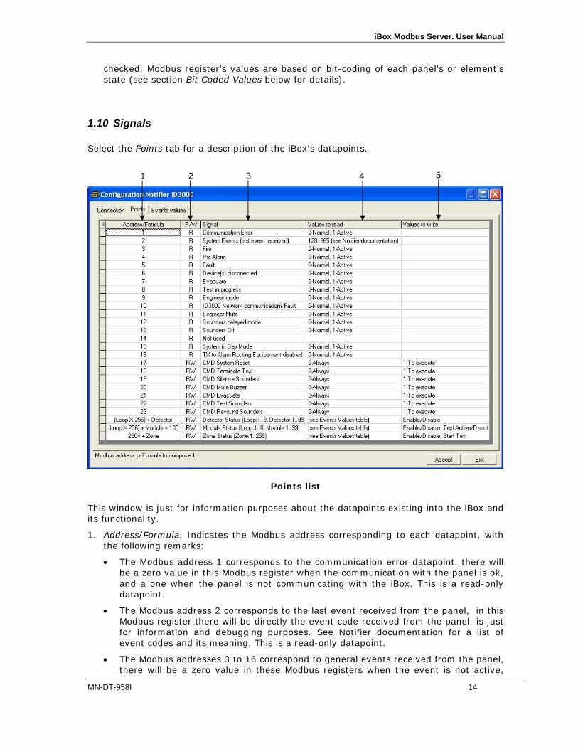
1.10 Signals Select the Points tab for a description of the iBox's datapoints.
Points list This window is just for information purposes about the datapoints existing into the iBox and its functionality.
1. Address/Formula. Indicates the Modbus address corresponding to each datapoint, with the following remarks:
The Modbus address 1 corresponds to the communication error datapoint, there will be a zero value in this Modbus register when the communication with the panel is ok, and a one when the panel is not communicating with the iBox. This is a read-only datapoint.
The Modbus address 2 corresponds to the last event received from the panel, in this Modbus register there will be directly the event code received from the panel, is just for information and debugging purposes. See Notifier documentation for a list of event codes and its meaning. This is a read-only datapoint.
The Modbus addresses 3 to 16 correspond to general events received from the panel, there will be a zero value in these Modbus registers when the event is not active,
1 2 3 4 5

iBox Modbus Server. User Manual
MN-DT-958I 15
and a one when it is active. See description of each event in "signal" column. These are read-only datapoints.
The Modbus addresses 17 to 23 correspond to general commands to send to the panel. Writing a one in these Modbus registers will send the corresponding command to the panel. See description of each command in "signal" column. These are read/write datapoints, although a read of them will always return zero value.
The Modbus addresses 257 to 2559 correspond to states of Detectors, Modules and Zones. These datapoints are of type read and write, this means you will read in these Modbus addresses the value corresponding to the state of the associated detector, module or zone, the value read being the one defined for the corresponding state in tab Event Values or Bit Coded Values (see below), and you can write also the corresponding value to send a command to the panel. The only commands permitted for detectors are enable/disable, for modules enable/disable and activate/deactivate test, and for zones enable/disable and start/stop test.
To know which Modbus register address correspond to which detector, module or zone, use the following formula:
For detectors
Modbus address = (Loop x 256) + detector
Loop: 1 to 8
Detectors: 1 to 99
For modules
Modbus address = (Loop x 256) + module + 100
Loop: 1 to 8
Modules: 1 to 99
For zones
Modbus address = zone + 2304
Zones: 1 to 255
See at the end of this document a table with the full Modbus address map.

iBox Modbus Server. User Manual
MN-DT-958I 16
1.11 Event values Select the Event Values tab to configure the value desired in the Modbus register for each possible event of the panel. This tab is only available when checkbox States in Modbus Registers Bit Coded is unchecked in Connection tab.
Points list This window is just a relation table between the event codes used by the panel and the values reflecting these event codes in the Modbus registers.
1. Modbus Value. Indicates the value that will appear in the Modbus register when this event is sent by the panel. When the event disappears, then the value in the Modbus register returns to zero. Entering a value of 255 here means that the value in the Modbus register will be the same as of the panel code for the event (the one indicated in column "Event"). Entering a value of 254 here means that this event will not be taken into account by the iBox.
2. Event. Indicates the code used by the panel for each event, just for your information.
3. Description. The description of each event, just for your information, in Spanish.
4. Description. The description of each event, just for your information, in English.
5. Write enabled for. Indicates which object in the panel accepts this event, just for your information.
Remarks:
The command test(FIRE) is only usable for Zones, and is just to test the fire alarm of the zone.
1 2 3 4 5
iBox Modbus Server. User Manual
MN-DT-958I 17
The commands device ENABLED and device DISABLED are usable for Detectors, Modules and Zones, and are just to enable/disable.
The commands output module test activation and output module test deactivation are usable only for Modules of type output, and are just to activate/deactivate the test of the module.
After receiving a panel’s reset event, all the values in Modbus registers return to zero.
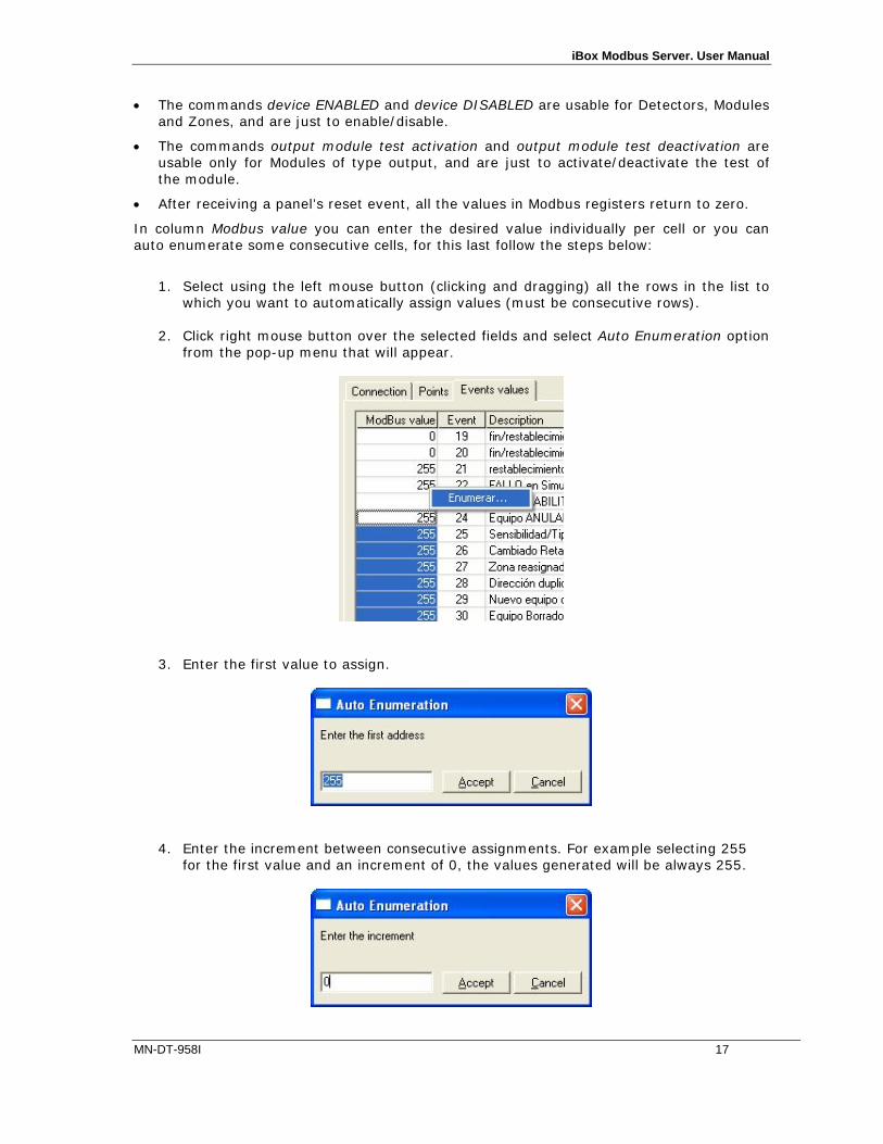
In column Modbus value you can enter the desired value individually per cell or you can auto enumerate some consecutive cells, for this last follow the steps below:
1. Select using the left mouse button (clicking and dragging) all the rows in the list to
which you want to automatically assign values (must be consecutive rows).
2. Click right mouse button over the selected fields and select Auto Enumeration option from the pop-up menu that will appear.
3. Enter the first value to assign.
4. Enter the increment between consecutive assignments. For example selecting 255
for the first value and an increment of 0, the values generated will be always 255.
iBox Modbus Server. User Manual
MN-DT-958I 18
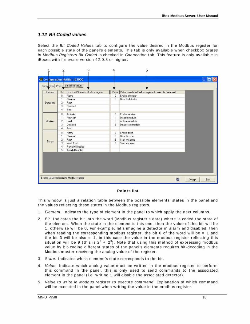
1.12 Bit Coded values Select the Bit Coded Values tab to configure the value desired in the Modbus register for each possible state of the panel’s elements. This tab is only available when checkbox States in Modbus Registers Bit Coded is checked in Connection tab. This feature is only available in iBoxes with firmware version 42.0.8 or higher.
Points list This window is just a relation table between the possible elements’ states in the panel and the values reflecting these states in the Modbus registers.
1. Element. Indicates the type of element in the panel to which apply the next columns.
2. Bit. Indicates the bit into the word (Modbus register’s data) where is coded the state of the element. When the state in the element is this one, then the value of this bit will be 1, otherwise will be 0. For example, let’s imagine a detector in alarm and disabled, then when reading the corresponding modbus register, the bit 0 of the word will be = 1 and the bit 3 will be also = 1, in this case the value in the modbus register reflecting this situation will be 9 (this is 20 + 23). Note that using this method of expressing modbus value by bit-coding different states of the panel’s elements requires bit-decoding in the Modbus master receiving the analog value of the register.
3. State. Indicates which element’s state corresponds to the bit.
4. Value. Indicate which analog value must be written in the modbus register to perform this command in the panel, this is only used to send commands to the associated element in the panel (i.e. writing 1 will disable the associated detector).
5. Value to write in Modbus register to execute command. Explanation of which command will be executed in the panel when writing the value in the modbus register.
1 2 3 4 5

iBox Modbus Server. User Manual
MN-DT-958I 19
1.13 Sending the configuration to iBox When the configuration has been saved (button Accept) and the iBox configuration binary file has been generated (remember to select yes when asked if you want to generate the iBox file), to send the configuration file to iBox click on the button Send File. The process of file transmission can be monitored in the iBox Communication Console window. If the file transmission is ok, iBox will reboot automatically with the new configuration loaded.
Remember that saving the configuration and generating the iBox bin file only saves to the hard disk on the PC the configuration files. Do not forget to send the configuration binary file to the iBox (using button Send File) after saving the configuration.

iBox Modbus Server. User Manual
MN-DT-958I 20
1.14 Signals viewer Once iBox is running with the correct configuration, to supervise the status of the configured signals, select menu View -> Signals. The Signals Viewer window will be opened. This window shows all the active iBox's signals with its main configuration parameters and its real time value in the column Value. After a reset of iBox or after sending a configuration file to the iBox, all the signal's values will be updated automatically in the signals viewer, in case you connect to the iBox when it is already running, you should press the Update button to get updated values, press just once the button to update all the signal values, from this moment the signal values will be maintained updated until the connection is closed.
The signals viewer can be used although only one system is connected to the iBox, Notifier or Modbus, and is very useful for supervision and test. It is possible to force a specific value to any signal for test purposes, to do so just double click on the row and select the desired value and Accept in the Data Test window. The new value entered will be available through the Modbus interface, the same way as if it has been received from the Notifier panel.

iBox Modbus Server. User Manual
MN-DT-958I 21
This tool is very useful to test the communication in the Modbus side from the Modbus master device for example, without the need to have the Notifier panel connected and running. The signals viewer window has a button to copy to the Windows Clipboard all the contents of the window (in tab separated text format).
1.15 System commands LinkBoxMB includes an option to send to iBox a set of system commands for debugging and control purposes; this list is available in the commands list as shown in the figure below. To send a command to iBox just select it from the list, or type it with the correct format, and press Enter or click on button Send. iBox will act accordingly with the command received; the process can be monitored in the iBox Communication Console window. The use of some of these commands can be critical for iBox normal functioning, having this in mind use only these commands following the recommendations of Software technical support. A list of the more commonly used commands and the way to use them will be returned by iBox after sending the HELP command.

iBox Modbus Server. User Manual
MN-DT-958I 22
1.16 Files LinkBoxMB saves the integration configuration in the following files inside the project folder: PROJECT.INI .ini file containing general information referent to the project
NOTIFIERID3000.INI .ini file containing the information referent to the connection
window and other special adjustments NOTIFIERID3000.EVT Text file (tab separated values) with the event values
information (Event values list). NOTIFIERID3000.LBOX Binary file created from the information in the two files described
above. This is the file downloaded to the iBox. It is strongly recommended to back up the project folder containing these files in external media, once the installation process is finished. This way you will be able to do future configuration changes in case of reinstallation of LinkBoxMB due, for example, to a failure of the hard disk in the PC where LinkBoxMB was installed. The configuration cannot be uploaded from iBox to LinkBoxMB, only can be downloaded.
iBox Modbus Server. User Manual
MN-DT-958I 23
Set-up process and troubleshooting
1.17 Pre-requisites It is necessary to have the Modbus master device operative and well connected to the Modbus port of iBox, remember to respect the maximum of 15 meters cable distance if using RS232 communication. It is necessary to have the Notifier panel with an RS232 port operative and at a distance of iBox installation site of 15 meters maximum (due to RS232 communication). Connectors, connection cables, PC for LinkBoxMB, and other auxiliary material, if needed, are not supplied for this standard integration. The items supplied for this integration are:
iBox Modbus Server device with Notifer ID3000 external protocol firmware loaded. LinkBoxMB software to configure iBox. Console cable needed to download the configuration to iBox. Product documentation.
1.18 Set-up procedure 1. Install LinkBoxMB on your laptop, use the setup program supplied for this and follow the
instructions given by the Installation wizard. 2. Install iBox in the desired installation site. The mounting can be on DIN rail or on a
stable not vibrating surface (DIN rail mounted inside a metallic industrial cabinet connected to ground beside the Panel is recommended).
3. Connect the communication cable coming from the Modbus master device to the port
marked as Modbus of iBox (used either RS232, RS485 or Ethernet port depending on the type of Modbus communication to use). (See details for this communication cable in section Connections of this document).
4. Connect the communication cable coming from the RS232 port of the Notifier to the port
marked as Notifier of iBox. (See details for this communication cable in section Connections of this document).
5. Power up iBox. The supply voltage can be 9 to 30 Vdc or just 24 Vac. Take care of the
polarity of the supply voltage applied.
WARNING! In order to avoid earth loops that can damage iBox and/or any other equipment connected to it, we strongly recommend: The use of DC power supplies, floating or with the negative terminal connected to
earth. Never use a DC power supply with the positive terminal connected to earth.
The use of AC power supplies only if they are floating and not powering any other device.

iBox Modbus Server. User Manual
MN-DT-958I 24
6. Connect the communication cable coming from the serial port of your laptop PC to the port marked as PC Console of iBox. (See details for this communication cable in section Connections of this document).
7. Open LinkBoxMB, create a new project selecting a copy of the one named DEMO
Notifier ID3000 and give it the name desired, select the serial port used to connect to iBox (menu Configuration -> Connection) and switch working mode to on-line (checkbox off-line/on-line). The iBox identification must appear in the iBox communication console window as showed below.
8. Modify the configuration as desired, save it and download the configuration file to iBox
as explained before. 9. Open the Modbus Communication Viewer window (menu View -> Bus -> Modbus) and
check that there is communication activity, some TX frames and some other rx frames. This means that the communication with the Modbus master device is ok. In case there is no communication activity between iBox and the Modbus master device check that it is operative, check the baud rate, and check also the communication cable used to connect both devices. (See details for this communication cable in section Connections of this document).
10. Open the External Protocol Communication Viewer window (menu View -> Bus Notifier
ID3000) and check that there is communication activity, some RX frames as showed in the figure below. This means that the communication with the Notifier panel is ok. In case of no communication activity between iBox and Notifier, check that the RS232 port

iBox Modbus Server. User Manual
MN-DT-958I 25
of Notifier panel is operative and well configured, and check also the communication cable used to connect both devices. (See details for this communication cable in section Connections of this document).

iBox Modbus Server. User Manual
MN-DT-958I 26
Connections
iBox (RJ45 F)
C1 Modbus TCPConnection
Master TCP Device
(RJ45 F) Cable
(RJ45 M) Ethernet Cable
(RJ45 M) Cable UTP/FTP Cat5 Crossed 1 device
Cable UTP/FTP Cat5 Straight Hub N devices
iBox (DB9 M)
C2 Modbus RTU Connection Master RTU(DB9 M)
Cable (DB9 F)
RS-232(Crossed)
Cable (DB9 F)
RX 2 2 RX TX 3 3 TX
GND 5 5 GND Cable
(DB9 F) or RS-485
TX/RX+ + TX/RX+ TX/RX- - TX/RX-
C2
C1
C3
Ethernet RJ45
PC Console
ETH
PC (LinkBoxMB)
- +
Modbus RTU RS485 RS232
Modbus TCP
- + CMN 24Vac
Power
C4
Notifier

iBox Modbus Server. User Manual
MN-DT-958I 27
iBox (DB9 F)
C3 PC Connection (LinkBoxMB) PC (DB9 M)
Cable (DB9 M)
RS-232(Straight)
Cable (DB9 F)
TX 2 2 RX RX 3 3 TX
GND 5 5 GND
iBox
(DB9 M)
C4 Notifier connection through ISO-RS232
optional card (RS232 in a terminal block)
Notifier ISO-RS232
card
Cable (DB9 F)
Cable
RX 2 2 TX TX 3 3 RX
GND 5 1 GND
iBox (DB9 M)
C4
Notifier connection through RS232 on main board
(RS232 in a DB9 connector)
Notifier RS232 on
main board (DB9 F)
Cable (DB9 F)
Cable (DB9 M)
RX 2 2 TX TX 3 3 RX
GND 5 5 GND
1 2 4

iBox Modbus Server. User Manual
MN-DT-958I 28
Mechanical & electrical characteristics
Enclosure Plastic, type PC (UL 94 V-0). Dimensions: 107mm x 105mm x 58mm.
Colour Light Grey. RAL 7035. Power 9 to 30Vdc +/-10% 1.4W.
24Vac +/-10% 1.4VA. Plug-in terminal bloc for power connection (2 poles).
Mounting Surface. Wall. DIN rail EN60715 TH35.
Modbus TCP port 1 x Ethernet 10BT RJ45.
Modbus RTU ports 1 x RS232. DB9 male connector (DTE). 1 x RS485. Plug-in terminal bloc (2 poles).
Notifier port 1 x RS232. DB9 male connector (DTE). LED indicators 1 x Power.
2 x Notifier port activity (Tx, Rx). 2 x Modbus RTU port activity (Tx, Rx). 2 x Ethernet port link and activity (LNK, ACT).
Console port RS232. DB9 female connector (DCE). Configuration Via console port.1 Firmware Allows upgrades via console port. Operational temperature
-40°C to +70°C
Operational humidity
5% to 95%, non condensing
Protection IP20 (IEC60529). RoHS conformity Compliant with RoHS directive (2002/95/CE). Certifications CE
1 Standard cable DB9male-DB9female 1,8 meters long is supplied with the device for connection to a PC COM port for
configuring and monitoring the device. The configuration software, compatible with Windows® operating systems, is also supplied.
iBox Modbus Server. User Manual
MN-DT-958I 29
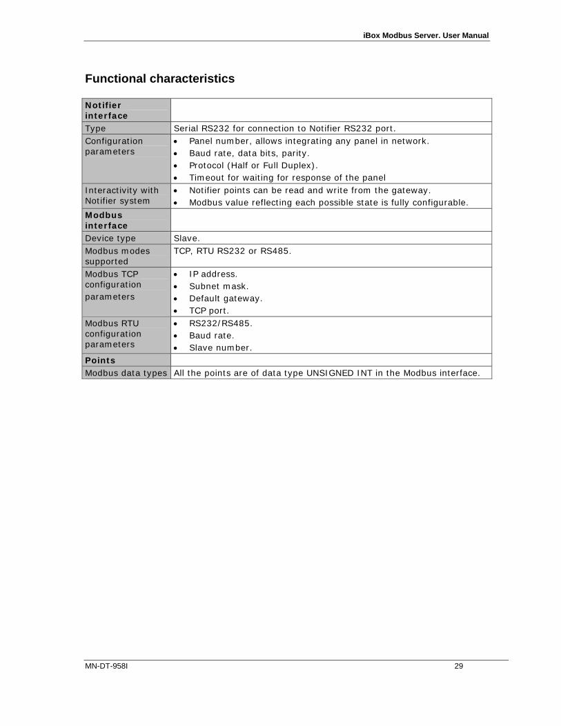
Functional characteristics Notifier interface
Type Serial RS232 for connection to Notifier RS232 port. Configuration parameters
Panel number, allows integrating any panel in network. Baud rate, data bits, parity. Protocol (Half or Full Duplex). Timeout for waiting for response of the panel
Interactivity with Notifier system
Notifier points can be read and write from the gateway. Modbus value reflecting each possible state is fully configurable.
Modbus interface
Device type Slave. Modbus modes supported
TCP, RTU RS232 or RS485.
Modbus TCP configuration parameters
IP address. Subnet mask. Default gateway. TCP port.
Modbus RTU configuration parameters
RS232/RS485. Baud rate. Slave number.
Points Modbus data types All the points are of data type UNSIGNED INT in the Modbus interface.

iBox Modbus Server. User Manual
MN-DT-958I 30
Dimensions
Recommended available space for its installation into a cabinet (wall or DIN rail mounting), with space enough for external connections
115 mm 130 mm
100 mm
Power+
Ethernet port
107 mm 105 mm
58 mm Console
port
Modbus RTUports
Notifier port

iBox Modbus Server. User Manual
MN-DT-958I 31
Modbus address map The following tables show the whole Modbus address map of the iBox (Addr means Modbus register address). Loop 1 2 3 4
Detector Addr Module Addr Detector Addr Module Addr Detector Addr Module Addr Detector Addr Module Addr
1 257 1 357 1 513 1 613 1 769 1 869 1 1025 1 1125
2 258 2 358 2 514 2 614 2 770 2 870 2 1026 2 1126
3 259 3 359 3 515 3 615 3 771 3 871 3 1027 3 1127
4 260 4 360 4 516 4 616 4 772 4 872 4 1028 4 1128
5 261 5 361 5 517 5 617 5 773 5 873 5 1029 5 1129
6 262 6 362 6 518 6 618 6 774 6 874 6 1030 6 1130
7 263 7 363 7 519 7 619 7 775 7 875 7 1031 7 1131
8 264 8 364 8 520 8 620 8 776 8 876 8 1032 8 1132
9 265 9 365 9 521 9 621 9 777 9 877 9 1033 9 1133
10 266 10 366 10 522 10 622 10 778 10 878 10 1034 10 1134
11 267 11 367 11 523 11 623 11 779 11 879 11 1035 11 1135
12 268 12 368 12 524 12 624 12 780 12 880 12 1036 12 1136
13 269 13 369 13 525 13 625 13 781 13 881 13 1037 13 1137
14 270 14 370 14 526 14 626 14 782 14 882 14 1038 14 1138
15 271 15 371 15 527 15 627 15 783 15 883 15 1039 15 1139
16 272 16 372 16 528 16 628 16 784 16 884 16 1040 16 1140
17 273 17 373 17 529 17 629 17 785 17 885 17 1041 17 1141
18 274 18 374 18 530 18 630 18 786 18 886 18 1042 18 1142
19 275 19 375 19 531 19 631 19 787 19 887 19 1043 19 1143
20 276 20 376 20 532 20 632 20 788 20 888 20 1044 20 1144
21 277 21 377 21 533 21 633 21 789 21 889 21 1045 21 1145
22 278 22 378 22 534 22 634 22 790 22 890 22 1046 22 1146
23 279 23 379 23 535 23 635 23 791 23 891 23 1047 23 1147
24 280 24 380 24 536 24 636 24 792 24 892 24 1048 24 1148
25 281 25 381 25 537 25 637 25 793 25 893 25 1049 25 1149
26 282 26 382 26 538 26 638 26 794 26 894 26 1050 26 1150
27 283 27 383 27 539 27 639 27 795 27 895 27 1051 27 1151
28 284 28 384 28 540 28 640 28 796 28 896 28 1052 28 1152
29 285 29 385 29 541 29 641 29 797 29 897 29 1053 29 1153
30 286 30 386 30 542 30 642 30 798 30 898 30 1054 30 1154
31 287 31 387 31 543 31 643 31 799 31 899 31 1055 31 1155
32 288 32 388 32 544 32 644 32 800 32 900 32 1056 32 1156
33 289 33 389 33 545 33 645 33 801 33 901 33 1057 33 1157
34 290 34 390 34 546 34 646 34 802 34 902 34 1058 34 1158
35 291 35 391 35 547 35 647 35 803 35 903 35 1059 35 1159
36 292 36 392 36 548 36 648 36 804 36 904 36 1060 36 1160
37 293 37 393 37 549 37 649 37 805 37 905 37 1061 37 1161
38 294 38 394 38 550 38 650 38 806 38 906 38 1062 38 1162
39 295 39 395 39 551 39 651 39 807 39 907 39 1063 39 1163
40 296 40 396 40 552 40 652 40 808 40 908 40 1064 40 1164
41 297 41 397 41 553 41 653 41 809 41 909 41 1065 41 1165
42 298 42 398 42 554 42 654 42 810 42 910 42 1066 42 1166
43 299 43 399 43 555 43 655 43 811 43 911 43 1067 43 1167
44 300 44 400 44 556 44 656 44 812 44 912 44 1068 44 1168
45 301 45 401 45 557 45 657 45 813 45 913 45 1069 45 1169
46 302 46 402 46 558 46 658 46 814 46 914 46 1070 46 1170
47 303 47 403 47 559 47 659 47 815 47 915 47 1071 47 1171
48 304 48 404 48 560 48 660 48 816 48 916 48 1072 48 1172
49 305 49 405 49 561 49 661 49 817 49 917 49 1073 49 1173
50 306 50 406 50 562 50 662 50 818 50 918 50 1074 50 1174
51 307 51 407 51 563 51 663 51 819 51 919 51 1075 51 1175
52 308 52 408 52 564 52 664 52 820 52 920 52 1076 52 1176
53 309 53 409 53 565 53 665 53 821 53 921 53 1077 53 1177
54 310 54 410 54 566 54 666 54 822 54 922 54 1078 54 1178
55 311 55 411 55 567 55 667 55 823 55 923 55 1079 55 1179
56 312 56 412 56 568 56 668 56 824 56 924 56 1080 56 1180
57 313 57 413 57 569 57 669 57 825 57 925 57 1081 57 1181
58 314 58 414 58 570 58 670 58 826 58 926 58 1082 58 1182
59 315 59 415 59 571 59 671 59 827 59 927 59 1083 59 1183
60 316 60 416 60 572 60 672 60 828 60 928 60 1084 60 1184
61 317 61 417 61 573 61 673 61 829 61 929 61 1085 61 1185
62 318 62 418 62 574 62 674 62 830 62 930 62 1086 62 1186
63 319 63 419 63 575 63 675 63 831 63 931 63 1087 63 1187
64 320 64 420 64 576 64 676 64 832 64 932 64 1088 64 1188
65 321 65 421 65 577 65 677 65 833 65 933 65 1089 65 1189
66 322 66 422 66 578 66 678 66 834 66 934 66 1090 66 1190

iBox Modbus Server. User Manual
MN-DT-958I 32
67 323 67 423 67 579 67 679 67 835 67 935 67 1091 67 1191
68 324 68 424 68 580 68 680 68 836 68 936 68 1092 68 1192
69 325 69 425 69 581 69 681 69 837 69 937 69 1093 69 1193
70 326 70 426 70 582 70 682 70 838 70 938 70 1094 70 1194
71 327 71 427 71 583 71 683 71 839 71 939 71 1095 71 1195
72 328 72 428 72 584 72 684 72 840 72 940 72 1096 72 1196
73 329 73 429 73 585 73 685 73 841 73 941 73 1097 73 1197
74 330 74 430 74 586 74 686 74 842 74 942 74 1098 74 1198
75 331 75 431 75 587 75 687 75 843 75 943 75 1099 75 1199
76 332 76 432 76 588 76 688 76 844 76 944 76 1100 76 1200
77 333 77 433 77 589 77 689 77 845 77 945 77 1101 77 1201
78 334 78 434 78 590 78 690 78 846 78 946 78 1102 78 1202
79 335 79 435 79 591 79 691 79 847 79 947 79 1103 79 1203
80 336 80 436 80 592 80 692 80 848 80 948 80 1104 80 1204
81 337 81 437 81 593 81 693 81 849 81 949 81 1105 81 1205
82 338 82 438 82 594 82 694 82 850 82 950 82 1106 82 1206
83 339 83 439 83 595 83 695 83 851 83 951 83 1107 83 1207
84 340 84 440 84 596 84 696 84 852 84 952 84 1108 84 1208
85 341 85 441 85 597 85 697 85 853 85 953 85 1109 85 1209
86 342 86 442 86 598 86 698 86 854 86 954 86 1110 86 1210
87 343 87 443 87 599 87 699 87 855 87 955 87 1111 87 1211
88 344 88 444 88 600 88 700 88 856 88 956 88 1112 88 1212
89 345 89 445 89 601 89 701 89 857 89 957 89 1113 89 1213
90 346 90 446 90 602 90 702 90 858 90 958 90 1114 90 1214
91 347 91 447 91 603 91 703 91 859 91 959 91 1115 91 1215
92 348 92 448 92 604 92 704 92 860 92 960 92 1116 92 1216
93 349 93 449 93 605 93 705 93 861 93 961 93 1117 93 1217
94 350 94 450 94 606 94 706 94 862 94 962 94 1118 94 1218
95 351 95 451 95 607 95 707 95 863 95 963 95 1119 95 1219
96 352 96 452 96 608 96 708 96 864 96 964 96 1120 96 1220
97 353 97 453 97 609 97 709 97 865 97 965 97 1121 97 1221
98 354 98 454 98 610 98 710 98 866 98 966 98 1122 98 1222
99 355 99 455 99 611 99 711 99 867 99 967 99 1123 99 1223
Loop 5 6 7 8
Detector Addr Module Addr Detector Addr Module Addr Detector Addr Module Addr Detector Addr Module Addr
1 1281 1 1381 1 1537 1 1637 1 1793 1 1893 1 2049 1 2149
2 1282 2 1382 2 1538 2 1638 2 1794 2 1894 2 2050 2 2150
3 1283 3 1383 3 1539 3 1639 3 1795 3 1895 3 2051 3 2151
4 1284 4 1384 4 1540 4 1640 4 1796 4 1896 4 2052 4 2152
5 1285 5 1385 5 1541 5 1641 5 1797 5 1897 5 2053 5 2153
6 1286 6 1386 6 1542 6 1642 6 1798 6 1898 6 2054 6 2154
7 1287 7 1387 7 1543 7 1643 7 1799 7 1899 7 2055 7 2155
8 1288 8 1388 8 1544 8 1644 8 1800 8 1900 8 2056 8 2156
9 1289 9 1389 9 1545 9 1645 9 1801 9 1901 9 2057 9 2157
10 1290 10 1390 10 1546 10 1646 10 1802 10 1902 10 2058 10 2158
11 1291 11 1391 11 1547 11 1647 11 1803 11 1903 11 2059 11 2159
12 1292 12 1392 12 1548 12 1648 12 1804 12 1904 12 2060 12 2160
13 1293 13 1393 13 1549 13 1649 13 1805 13 1905 13 2061 13 2161
14 1294 14 1394 14 1550 14 1650 14 1806 14 1906 14 2062 14 2162
15 1295 15 1395 15 1551 15 1651 15 1807 15 1907 15 2063 15 2163
16 1296 16 1396 16 1552 16 1652 16 1808 16 1908 16 2064 16 2164
17 1297 17 1397 17 1553 17 1653 17 1809 17 1909 17 2065 17 2165
18 1298 18 1398 18 1554 18 1654 18 1810 18 1910 18 2066 18 2166
19 1299 19 1399 19 1555 19 1655 19 1811 19 1911 19 2067 19 2167
20 1300 20 1400 20 1556 20 1656 20 1812 20 1912 20 2068 20 2168
21 1301 21 1401 21 1557 21 1657 21 1813 21 1913 21 2069 21 2169
22 1302 22 1402 22 1558 22 1658 22 1814 22 1914 22 2070 22 2170
23 1303 23 1403 23 1559 23 1659 23 1815 23 1915 23 2071 23 2171
24 1304 24 1404 24 1560 24 1660 24 1816 24 1916 24 2072 24 2172
25 1305 25 1405 25 1561 25 1661 25 1817 25 1917 25 2073 25 2173
26 1306 26 1406 26 1562 26 1662 26 1818 26 1918 26 2074 26 2174
27 1307 27 1407 27 1563 27 1663 27 1819 27 1919 27 2075 27 2175
28 1308 28 1408 28 1564 28 1664 28 1820 28 1920 28 2076 28 2176
29 1309 29 1409 29 1565 29 1665 29 1821 29 1921 29 2077 29 2177
30 1310 30 1410 30 1566 30 1666 30 1822 30 1922 30 2078 30 2178
31 1311 31 1411 31 1567 31 1667 31 1823 31 1923 31 2079 31 2179
32 1312 32 1412 32 1568 32 1668 32 1824 32 1924 32 2080 32 2180
33 1313 33 1413 33 1569 33 1669 33 1825 33 1925 33 2081 33 2181
34 1314 34 1414 34 1570 34 1670 34 1826 34 1926 34 2082 34 2182
35 1315 35 1415 35 1571 35 1671 35 1827 35 1927 35 2083 35 2183
36 1316 36 1416 36 1572 36 1672 36 1828 36 1928 36 2084 36 2184
37 1317 37 1417 37 1573 37 1673 37 1829 37 1929 37 2085 37 2185
38 1318 38 1418 38 1574 38 1674 38 1830 38 1930 38 2086 38 2186
39 1319 39 1419 39 1575 39 1675 39 1831 39 1931 39 2087 39 2187

iBox Modbus Server. User Manual
MN-DT-958I 33
40 1320 40 1420 40 1576 40 1676 40 1832 40 1932 40 2088 40 2188
41 1321 41 1421 41 1577 41 1677 41 1833 41 1933 41 2089 41 2189
42 1322 42 1422 42 1578 42 1678 42 1834 42 1934 42 2090 42 2190
43 1323 43 1423 43 1579 43 1679 43 1835 43 1935 43 2091 43 2191
44 1324 44 1424 44 1580 44 1680 44 1836 44 1936 44 2092 44 2192
45 1325 45 1425 45 1581 45 1681 45 1837 45 1937 45 2093 45 2193
46 1326 46 1426 46 1582 46 1682 46 1838 46 1938 46 2094 46 2194
47 1327 47 1427 47 1583 47 1683 47 1839 47 1939 47 2095 47 2195
48 1328 48 1428 48 1584 48 1684 48 1840 48 1940 48 2096 48 2196
49 1329 49 1429 49 1585 49 1685 49 1841 49 1941 49 2097 49 2197
50 1330 50 1430 50 1586 50 1686 50 1842 50 1942 50 2098 50 2198
51 1331 51 1431 51 1587 51 1687 51 1843 51 1943 51 2099 51 2199
52 1332 52 1432 52 1588 52 1688 52 1844 52 1944 52 2100 52 2200
53 1333 53 1433 53 1589 53 1689 53 1845 53 1945 53 2101 53 2201
54 1334 54 1434 54 1590 54 1690 54 1846 54 1946 54 2102 54 2202
55 1335 55 1435 55 1591 55 1691 55 1847 55 1947 55 2103 55 2203
56 1336 56 1436 56 1592 56 1692 56 1848 56 1948 56 2104 56 2204
57 1337 57 1437 57 1593 57 1693 57 1849 57 1949 57 2105 57 2205
58 1338 58 1438 58 1594 58 1694 58 1850 58 1950 58 2106 58 2206
59 1339 59 1439 59 1595 59 1695 59 1851 59 1951 59 2107 59 2207
60 1340 60 1440 60 1596 60 1696 60 1852 60 1952 60 2108 60 2208
61 1341 61 1441 61 1597 61 1697 61 1853 61 1953 61 2109 61 2209
62 1342 62 1442 62 1598 62 1698 62 1854 62 1954 62 2110 62 2210
63 1343 63 1443 63 1599 63 1699 63 1855 63 1955 63 2111 63 2211
64 1344 64 1444 64 1600 64 1700 64 1856 64 1956 64 2112 64 2212
65 1345 65 1445 65 1601 65 1701 65 1857 65 1957 65 2113 65 2213
66 1346 66 1446 66 1602 66 1702 66 1858 66 1958 66 2114 66 2214
67 1347 67 1447 67 1603 67 1703 67 1859 67 1959 67 2115 67 2215
68 1348 68 1448 68 1604 68 1704 68 1860 68 1960 68 2116 68 2216
69 1349 69 1449 69 1605 69 1705 69 1861 69 1961 69 2117 69 2217
70 1350 70 1450 70 1606 70 1706 70 1862 70 1962 70 2118 70 2218
71 1351 71 1451 71 1607 71 1707 71 1863 71 1963 71 2119 71 2219
72 1352 72 1452 72 1608 72 1708 72 1864 72 1964 72 2120 72 2220
73 1353 73 1453 73 1609 73 1709 73 1865 73 1965 73 2121 73 2221
74 1354 74 1454 74 1610 74 1710 74 1866 74 1966 74 2122 74 2222
75 1355 75 1455 75 1611 75 1711 75 1867 75 1967 75 2123 75 2223
76 1356 76 1456 76 1612 76 1712 76 1868 76 1968 76 2124 76 2224
77 1357 77 1457 77 1613 77 1713 77 1869 77 1969 77 2125 77 2225
78 1358 78 1458 78 1614 78 1714 78 1870 78 1970 78 2126 78 2226
79 1359 79 1459 79 1615 79 1715 79 1871 79 1971 79 2127 79 2227
80 1360 80 1460 80 1616 80 1716 80 1872 80 1972 80 2128 80 2228
81 1361 81 1461 81 1617 81 1717 81 1873 81 1973 81 2129 81 2229
82 1362 82 1462 82 1618 82 1718 82 1874 82 1974 82 2130 82 2230
83 1363 83 1463 83 1619 83 1719 83 1875 83 1975 83 2131 83 2231
84 1364 84 1464 84 1620 84 1720 84 1876 84 1976 84 2132 84 2232
85 1365 85 1465 85 1621 85 1721 85 1877 85 1977 85 2133 85 2233
86 1366 86 1466 86 1622 86 1722 86 1878 86 1978 86 2134 86 2234
87 1367 87 1467 87 1623 87 1723 87 1879 87 1979 87 2135 87 2235
88 1368 88 1468 88 1624 88 1724 88 1880 88 1980 88 2136 88 2236
89 1369 89 1469 89 1625 89 1725 89 1881 89 1981 89 2137 89 2237
90 1370 90 1470 90 1626 90 1726 90 1882 90 1982 90 2138 90 2238
91 1371 91 1471 91 1627 91 1727 91 1883 91 1983 91 2139 91 2239
92 1372 92 1472 92 1628 92 1728 92 1884 92 1984 92 2140 92 2240
93 1373 93 1473 93 1629 93 1729 93 1885 93 1985 93 2141 93 2241
94 1374 94 1474 94 1630 94 1730 94 1886 94 1986 94 2142 94 2242
95 1375 95 1475 95 1631 95 1731 95 1887 95 1987 95 2143 95 2243
96 1376 96 1476 96 1632 96 1732 96 1888 96 1988 96 2144 96 2244
97 1377 97 1477 97 1633 97 1733 97 1889 97 1989 97 2145 97 2245
98 1378 98 1478 98 1634 98 1734 98 1890 98 1990 98 2146 98 2246
99 1379 99 1479 99 1635 99 1735 99 1891 99 1991 99 2147 99 2247

iBox Modbus Server. User Manual
MN-DT-958I 34
Zone Addr Module Addr Detector Addr Module Addr Detector Addr Module Addr Detector Addr Module Addr
1 2305 33 2337 65 2369 97 2401 129 2433 161 2465 193 2497 225 2529
2 2306 34 2338 66 2370 98 2402 130 2434 162 2466 194 2498 226 2530
3 2307 35 2339 67 2371 99 2403 131 2435 163 2467 195 2499 227 2531
4 2308 36 2340 68 2372 100 2404 132 2436 164 2468 196 2500 228 2532
5 2309 37 2341 69 2373 101 2405 133 2437 165 2469 197 2501 229 2533
6 2310 38 2342 70 2374 102 2406 134 2438 166 2470 198 2502 230 2534
7 2311 39 2343 71 2375 103 2407 135 2439 167 2471 199 2503 231 2535
8 2312 40 2344 72 2376 104 2408 136 2440 168 2472 200 2504 232 2536
9 2313 41 2345 73 2377 105 2409 137 2441 169 2473 201 2505 233 2537
10 2314 42 2346 74 2378 106 2410 138 2442 170 2474 202 2506 234 2538
11 2315 43 2347 75 2379 107 2411 139 2443 171 2475 203 2507 235 2539
12 2316 44 2348 76 2380 108 2412 140 2444 172 2476 204 2508 236 2540
13 2317 45 2349 77 2381 109 2413 141 2445 173 2477 205 2509 237 2541
14 2318 46 2350 78 2382 110 2414 142 2446 174 2478 206 2510 238 2542
15 2319 47 2351 79 2383 111 2415 143 2447 175 2479 207 2511 239 2543
16 2320 48 2352 80 2384 112 2416 144 2448 176 2480 208 2512 240 2544
17 2321 49 2353 81 2385 113 2417 145 2449 177 2481 209 2513 241 2545
18 2322 50 2354 82 2386 114 2418 146 2450 178 2482 210 2514 242 2546
19 2323 51 2355 83 2387 115 2419 147 2451 179 2483 211 2515 243 2547
20 2324 52 2356 84 2388 116 2420 148 2452 180 2484 212 2516 244 2548
21 2325 53 2357 85 2389 117 2421 149 2453 181 2485 213 2517 245 2549
22 2326 54 2358 86 2390 118 2422 150 2454 182 2486 214 2518 246 2550
23 2327 55 2359 87 2391 119 2423 151 2455 183 2487 215 2519 247 2551
24 2328 56 2360 88 2392 120 2424 152 2456 184 2488 216 2520 248 2552
25 2329 57 2361 89 2393 121 2425 153 2457 185 2489 217 2521 249 2553
26 2330 58 2362 90 2394 122 2426 154 2458 186 2490 218 2522 250 2554
27 2331 59 2363 91 2395 123 2427 155 2459 187 2491 219 2523 251 2555
28 2332 60 2364 92 2396 124 2428 156 2460 188 2492 220 2524 252 2556
29 2333 61 2365 93 2397 125 2429 157 2461 189 2493 221 2525 253 2557
30 2334 62 2366 94 2398 126 2430 158 2462 190 2494 222 2526 254 2558
31 2335 63 2367 95 2399 127 2431 159 2463 191 2495 223 2527 255 2559
32 2336 64 2368 96 2400 128 2432 160 2464 192 2496 224 2528

iBox Modbus Server. User Manual
MN-DT-958I 35
Procedure to configure the RS232 port in the Notifier panel To enable the RS232 port of the main board, follow these steps in the menu of the panel (to unlock the keypad and have access the menu, turn the service key located on the front panel, beside the keypad, a quarter to the right):
6. Configuration
6. Panel Configuration
18. Conf. RS232 on main board
3. Integration protocol
9600 bps
Version: 1: 003A
Controls: disabled
Supervision com.: disabled
Supervision time: 0
In bold the compulsory selections.
Default Level 3 password: 27835
To enable the RS232 port of the ISO-RS232 optional card, follow these steps in the menu of the panel (to unlock the keypad and have access the menu, turn the service key located on the front panel, beside the keypad, a quarter to the right):
6. Configuration
6. Panel Configuration
18. Conf. Port RS232 isolated
3. Integration Protocol
2400 bps
Version: 2: 010A (only if Half Duplex is not available)
Controls: disabled
Supervision com.: disabled
Supervision time: 0
In bold the compulsory selections.
Default Level 3 password: 27835

iBox Modbus Server. User Manual
MN-DT-958I 36
Honeywell Life Safety IberiaPhone: 902 03 05 45 / T. International: +34 93 24 24 236
www.honeywelllifesafety.es / [email protected]