ic-a220 (non-tso) instruction manual
TRANSCRIPT
VHF AIR BAND TRANSCEIVER
INSTRUCTION MANUAL
This device complies with Part 15 of the FCC Rules. Operation is subject to the condition that this device does not cause harmful interference.
iA220
i
IMPORTANT
READ ALL INSTRUCTIONS carefully and completely before using the transceiver.
SAVE THIS INSTRUCTION MANUAL — This in-struction manual contains important operating instructions for the IC-A220.
The explicit definitions below apply to this instruction manual.
WORD DEFINITION
RWARNING!Personal injury, fire hazard or electric shock may occur.
CAUTION Equipment damage may occur.
NOTEIf disregarded, inconvenience only. No risk of personal injury, fire or electric shock.
Icom, Icom Inc. and Icom logo are registered trademarks of Icom Incorporated (Japan) in Japan, the United States, the United Kingdom, Germany, France, Spain, Russia, Australia, New Zealand, and/or other countries.
FCC INFORMATION• FOR CLASS A UNINTENTIONAL RADIATORS:This equipment has been tested and found to comply with the limits for a Class A digital device, pursuant to part 15 of the FCC Rules. These limits are designed to provide reasonable protection against harmful interference when the equipment is operated in a commercial environment. This equipment generates, uses and can radiate radio frequency energy and, if not installed and used in accordance with the instruction manual, may cause harmful interference to radio communi-cations. Operation of this equipment in a residential area is likely to cause harmful interference in which case the user will be required to correct the interference at his own expense.
• POUR LES RAYONNEMENTS NON INTENTIONNELS DE CLASSE A:
Cet équipement a été testé et reconnu conforme aux limites fixées pour un appareil numérique de classe A, conformément au point 15 de la réglementation FCC. Ces limites sont définies de façon à fournir une protection raisonnable contre le brouillage préjudiciable lorsque cet appareil est utilisé dans un environnement commercial. Cet équipement génère, utilise et peut émettre un rayonnement de fréquence radio. S'il n'a pas été installé conformément aux instruc-tions, il peut par ailleurs créer des interférences perturbant les com-munications radio.L'utilisation de cet appareil dans une zone résidentielle peut provo-quer un brouillage préjudiciable, auquel cas l'utilisateur sera tenu de corriger la situation à ses frais.
EXPLICIT DEFINITIONS
CAUTION: Changes or modifications to this transceiver, not expressly approved by Icom Inc., could void your authority to operate this transceiver under FCC regulations.
ii
DO NOT use or place the transceiver in direct sunlight or in areas with temperatures below –20°C (–4°F) or above +55°C (+131°F).
DO NOT place the transceiver in excessively dusty envi-ronments.
DO NOT use harsh solvents such as benzine or alcohol to clean the transceiver, as they will damage the transceiver’s surfaces. If the transceiver becomes dusty or dirty, wipe it clean with a soft, dry cloth.
BE CAREFUL! The transceiver will become hot when operating continuously for long periods of time.
PRECAUTIONS
R WARNING! NEVER operate the transceiver with an earphone or other audio accessories at high volume lev-els. Continuous high volume operation may cause a ringing in your ears. If you experience ringing, reduce the volume level or discontinue use.
R WARNING! NEVER connect the transceiver to an AC outlet or to a power source of more than 28 V DC. Such a connection will damage the transceiver.
CAUTION: NEVER connect the transceiver to a power source that is DC fused at more than 10 A. Accidental reverse connection will be protected by this fuse, higher fuse values will not give any protection against such accidents and the transceiver will be damaged.
DO NOT operate the transceiver near unshielded electric blasting caps or in an explosive atmosphere.
DO NOT connect the transceiver to a power source using reverse polarity. This connection will not only blow fuses but also may damage the transceiver.
DO NOT place unit in a non-secure place to avoid inadver-tent use by children.
DO NOT push the PTT when not actually intending to transmit.
CAUTION: Use of 8.33 kHz Channel Spacing of this radiois strictly prohibited and shall not be used in Canada.
Icom is not responsible for the destruction, damage to, or performance of any Icom or non-Icom equipment, if the mal-function is because of:• Force majeure, including, but not limited to, fires, earth-
quakes, storms, floods, lightning, other natural disasters, disturbances, riots, war, or radioactive contamination.
• The use of Icom transceivers with any equipment that is not manufactured or approved by Icom.
iii
NE PAS nettoyer l'appareil avec des solvants agressifs tels que benzène ou alcool, susceptibles d'endommager les sur-faces exposées du boîtier. En cas de dépôt de poussière ou de salissures sur l'émetteur-récepteur, il faut l'essuyer avec chiffon doux et sec.
ATTENTION! Le transceiver devient chaud lors d'utilisations continues de longue durée. L’émetteur-récepteur chauffe en cas d’utilisation continue sur une longue durée.
L'antenne doit être placée à au moins un mètre de la position de chacune des personnes à bord de l'aéronef.
PRÉCAUTIONS
R NE JAMAIS utiliser l’émetteur-récepteur avec un casque ou d’autres accessoires audio ayant un volume trop élevé. Un volume continu trop fort peut entraîner un bour-donnement dans vos oreilles. Si vous entendez une sonnerie baissez le niveau sonore ou interrompez l'utilisation.
R NE JAMAIS relier l'émetteurrécepteur à une prise d'alimentation de plus de 28 V. Un tel branchement endom-magerait votre émetteur-récepteur.
NE JAMAIS brancher l’émetteur-récepteur à une ali-mentation continue dont le fusible de protection excède 10 A. Ce fusible protège contre l’inversion accidentelle des branchements.
NE PAS utiliser l'émetteur-récepteur près d'amorces élec-triques non blindées ou en atmosphère explosive.
NE JAMAIS brancher le transceiver à une source d'alimentation employant la polarité inversée.
NE PAS appuyer sur la touche PTT lorsqu’on ne souhaite pas émettre.
NE PAS d’utiliser ou d’exposer l’émetteur-récepteur en plein soleil ou à une tem pérature ambiante inférieure à –20°C ou supérieure à +55°C.
NE PAS placer l'émetteur-récepteur dans des endroits ex-cessivement poussiéreux.
MISE EN GARDE: Utilisation de 8,33 kHz Espacement des canaux de cette radio est strictement interdite et ne doit pas être utilisé au Canada.
Icom ne peut pas être tenu pour responsable de la destruc-tion, de la détérioration ou des performances d'un équipe-ment Icom ou non-Icom, si le dysfonctionnement survient à cause de :• Force majeure, sans toutefois s'y limiter, les incendies,
tremblements de terre, tempêtes, inondations, la foudre, d'autres catastrophes naturelles, perturbations, émeutes, guerre, ou contamination radioactive.
• L'utilisation d'un émetteur-récepteur Icom avec tout équi-pement non fabriqué ou approuvé par Icom.
iv
SAFETY TRAINING INFORMATION Your Icom radio generates RF electromag-netic energy during transmit mode. This radio is designed for and classified as “Oc-cupational Use Only,” meaning it must be used only during the course of employment by individuals aware of the hazards, and the ways to minimize such hazards. This radio is NOT intended for use by the “General Population” in an uncontrolled environment.
• For compliance with FCC and Industry Canada RF Expo-sure Requirements, the transmitter antenna installation shall comply with the following two conditions:
1. The transmitter antenna gain shall not exceed 0 dBi.
2. The antenna is required to be located outside of a ve-hicle and kept at a distance of 40 centimeters or more between the transmitting antenna of this device and any persons during operation. For a small vehicle, the an-tenna as worst case, the antenna shall be located on the roof top at any place on the centre line along the vehicle in order to achieve 40 centimeters separation distance. In order to ensure this distance is met, the installation of the antenna must be mounted at least 40 centimeters away from the nearest edge of the vehicle in order to protect against exposure to bystanders.
To ensure that your exposure to RF elec-tromagnetic energy is within the FCC al-lowable limits for occupational use, always adhere to the following guidelines:
• DO NOT operate the radio without a proper antenna at-tached, as this may damage the radio and may also cause you to exceed FCC RF exposure limits. A proper antenna is the antenna supplied with this radio by the manufacturer or an antenna specifically authorized by the manufacturer for use with this radio.
• DO NOT transmit for more than 50% of total radio use time (“50% duty cycle”). Transmitting more than 50% of the time can cause FCC RF exposure compliance requirements to be exceeded. The radio is transmitting when the “TX” indica-tor appears. You can cause the radio to transmit by pressing the PTT switch.
Electromagnetic Interference/CompatibilityDuring transmissions, your Icom radio generates RF energy that can possibly cause interference with other devices or systems. To avoid such interference, turn off the radio in ar-eas where signs are posted to do so. DO NOT operate the transmitter in areas that are sensitive to electromagnetic ra-diation such as hospitals, and blasting sites.
v
INFORMATION EN MATIÈRE DE SÉCURITÉ Votre radio Icom produit une énergie électro-magnétique de radiofréquences (RF), en mode de transmission. Cette radio est conçue pour un «usage professionnel seulement» et classée comme tel, ce qui signifie qu'elle doit être utili-sée uniquement dans le cadre d'un travail par des personnes conscientes des dangers et des mesures visant à minimiser ces dangers. Elle N'EST PAS conçue pour une «utilisation grand public», dans un environnement non contrôlé.
• Afin de satisfaire aux exigences de la FCC et d'Industrie Canada en matière d'exposition aux RF, il est nécessaire que l'antenne soit installée confor-mément aux deux conditions suivantes:
1. Le gain de l'antenne du radio émetteur ne doit pas dépasser 0 dBi.
2. Il faut que l'antenne émettrice de cet appareil soit placée à l'extérieur d'un véhicule et tenue éloignée d'au moins 40 cen-timètres de toute personne pendant le fonctionnement. Dans le pire des cas, pour un petit véhicule, l'antenne doit être placée sur le toit, n'importe où dans l'axe central du véhicule, afin de respecter une distance de 40 cm du bord le plus rapproché du véhicule et ainsi éviter que les personnes présentes soient exposées.
Afin de vous assurer que votre exposition à une énergie électromagnétique de RF se situe dans les limites permises par la FCC pour une utilisation grand public, veuillez en tout temps respecter les directives suivantes:
• NE PAS faire fonctionner la radio sans qu'une antenne appropriée y soit fixée, car ceci risque d'endommager la radio et causer une exposition supérieure aux limites établies par la FCC. L'antenne ap-propriée est celle qui est fournie avec cette radio par le fabricant ou une antenne spécialement autorisée par le fabricant pour être utilisée avec cette radio.
• NE PAS émettre pendant plus de 50% du temps total d'utilisation de l'appareil («50% du facteur d'utilisation»). Émettre pendant plus de 50% du temps total d'utilisation peut causer une exposition aux RF supérieure aux limites établies par la FCC. La radio est en train d’émettre lorsque le témoin du mode de transmission s'affiche sur l'écran ACL. La radio émettra si vous appuyez sur le bouton du microphone.
Interférence électromagnétique et compatibilitéEn mode de transmission, votre radio Icom produit de l'énergie de RF qui peut provoquer des interférences avec d'autres appareils ou systèmes. Pour éviter de telles interférences, mettez la radio hors tension dans les secteurs où une signalisation l’exige. NE PAS faire fonctionner l'émetteur dans des secteurs sensibles au rayonnement électromagnétique tels que les hôpitaux et les sites de dynamitage.
AVERTISSEMENT MISE EN GARDE
vi
TABLE OF CONTENTSIMPORTANT .......................................................................... iEXPLICIT DEFINITIONS ....................................................... iFCC INFORMATION ............................................................. iPRECAUTIONS .................................................................... iiPRÉCAUTIONS ................................................................... iiiSAFETY TRAINING INFORMATION ................................... ivINFORMATION EN MATIÈRE DE SÉCURITÉ ..................... v
1 PANEL DESCRIPTION ............................................1–3■ Front panel ...................................................................1■ Rear panel ...................................................................2■ Function display ...........................................................32 BASIC OPERATION ................................................4–6■ General description ......................................................4■ Receiving and transmitting ...........................................5■ Directly setting the frequency .......................................6■ Squelch settings ...........................................................6
3 MEMORY OPERATION .........................................7–13■ General description ......................................................7■ Basic operation ............................................................8■ Editing Regular memory/Group memory channels ......8■ Selecting a weather memory channel .........................12■ History memory channel ............................................12■Selecting a GPS memory channel .............................13■ Editing GPS memory .................................................13
■ Protecting memory .....................................................13
4 OTHER FUNCTIONS ...........................................14–17■ Dualwatch operation ..................................................14■ Priority watch .............................................................14■ Using the lock function ...............................................15■ Accessing the 121.5 MHz emergency frequency .......15■ Enabling the intercom ................................................16■ Opening the squelch for test ......................................16■ Setting the frequency step .........................................16■ Using the remote control ............................................16■ Scanning the weather memory channels ...................175 MENU MODE .......................................................18–25■ Using the menu mode ................................................18■ Settings menu items ..................................................20■ Configuration menu items ..........................................226 OPTIONS ...................................................................267 SPECIFICATIONS .....................................................27INDEX ............................................................................29
1
1 PANEL DESCRIPTION
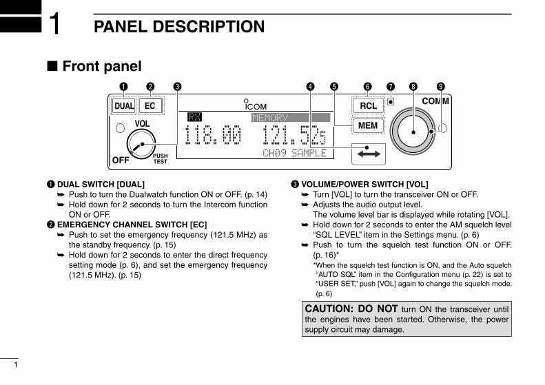
q DUAL SWITCH [DUAL] ➥ Push to turn the Dualwatch function ON or OFF. (p. 14) ➥ Hold down for 2 seconds to turn the Intercom function
ON or OFF.w EMERGENCY CHANNEL SWITCH [EC] ➥ Push to set the emergency frequency (121.5 MHz) as
the standby frequency. (p. 15) ➥ Hold down for 2 seconds to enter the direct frequency
setting mode (p. 6), and set the emergency frequency (121.5 MHz). (p. 15)
e VOLUME/POWER SWITCH [VOL] ➥ Turn [VOL] to turn the transceiver ON or OFF. ➥ Adjusts the audio output level. The volume level bar is displayed while rotating [VOL]. ➥ Hold down for 2 seconds to enter the AM squelch level
“SQL LEVEL” item in the Settings menu. (p. 6) ➥ Push to turn the squelch test function ON or OFF.
(p. 16)* * When the squelch test function is ON, and the Auto squelch
“AUTO SQL” item in the Configuration menu (p. 22) is set to “USER SET,” push [VOL] again to change the squelch mode. (p. 6)
RCL
MEM
OFF
VOL
PUSHTEST
COMMDUAL EC
CH09 SAMPLE
121.525118.00RX MEMORY
e ytr i ouq w
■ Front panel
CAUTION: DO NOT turn ON the transceiver until the engines have been started. Otherwise, the power supply circuit may damage.
r FREQUENCY EXCHANGE (FLIP-FLOP) SWITCH [ ] ➥ Push to exchange the standby frequency with the ac-
tive frequency. (p. 5) ➥ Hold down for 2 seconds to enter the direct frequency
setting mode. (p. 6)t MEMORY SWITCH [MEM] Hold down for 2 seconds to enter a displayed frequency
into any blank regular memory channel or delete or revive the selected memory channel (depending on the operating mode).
y RECALL SWITCH [RCL] ➥ Push to enter and exit the memory mode. (p. 8) ➥ Hold down for 2 seconds to enter the Settings menu. (p.
18) ➥ Push to exit the Settings menu. (p. 18)u LIGHT-SENSITIVE DETECTOR This detector senses ambient light. The detector is used to
automatically adjust “DISP LOW” or “DISP HIGH” (pp. 23, 24) when the “DISP MODE” (p. 23) is set to ‘AUTO.’
i INNER (Small) TUNING DIAL [DIAL] ➥ Rotate to set the standby frequencies (kHz digit) (p.
5), memory channels (p. 8), and menu mode settings. (pp. 18, 19)
➥ Hold down for 2 seconds to turn ON the dial/panel lock mode. (p. 15)
o OUTER (Large) TUNING DIAL [O-DIAL] Rotate to set the standby frequency (MHz digit) (p. 5),
group memory channel (p. 8), select the entry digit for group name (p. 10), and so on.
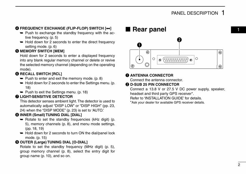
■ Rear panel
2
1PANEL DESCRIPTION
01
q w
e q
e
For regular type
Optional MBA-3
qw
e
q ANTENNA CONNECTOR Connect the antenna connector.w D-SUB 25 PIN CONNECTOR Connect a 13.8 V or 27.5 V DC power supply, speaker,
headset and third party GPS receiver*. Refer to ‘INSTALLATION GUIDE’ for details. *Ask your dealer for available GPS receiver details.
3
1 PANEL DESCRIPTION
3
■ Function display
CH09 SAMPLETEST
121.525118.00RX DUAL MEMORY RXICS
O F
D
TX
AU
e tr y e
io!2
uq
!1
w
!0
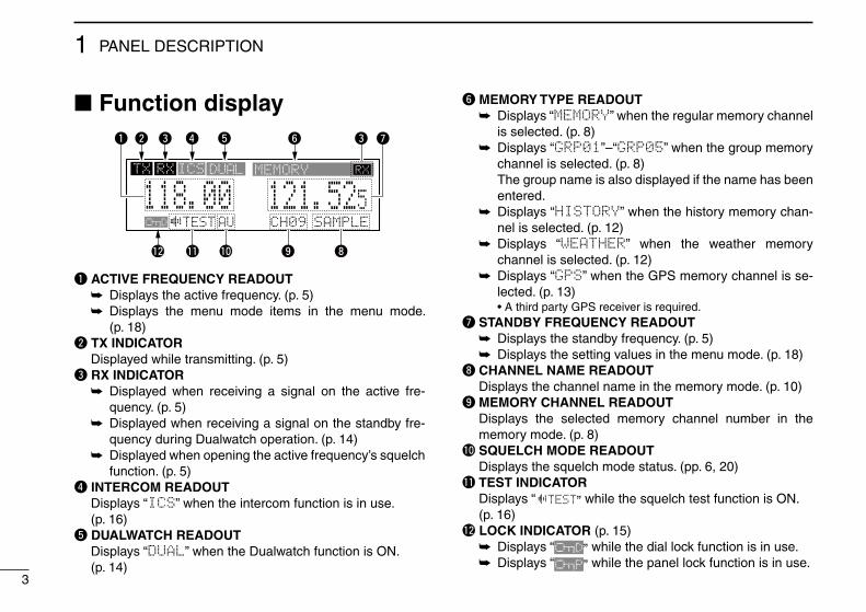
q ACTIVE FREQUENCY READOUT ➥ Displays the active frequency. (p. 5) ➥ Displays the menu mode items in the menu mode.
(p. 18)w TX INDICATOR Displayed while transmitting. (p. 5)e RX INDICATOR ➥ Displayed when receiving a signal on the active fre-
quency. (p. 5) ➥ Displayed when receiving a signal on the standby fre-
quency during Dualwatch operation. (p. 14) ➥ Displayed when opening the active frequency’s squelch
function. (p. 5)r INTERCOM READOUT Displays “ICS” when the intercom function is in use. (p. 16)t DUALWATCH READOUT Displays “DUAL” when the Dualwatch function is ON. (p. 14)
y MEMORY TYPE READOUT ➥ Displays “MEMORY” when the regular memory channel
is selected. (p. 8) ➥ Displays “GRP01”–“GRP05” when the group memory
channel is selected. (p. 8) The group name is also displayed if the name has been
entered. ➥ Displays “HISTORY” when the history memory chan-
nel is selected. (p. 12) ➥ Displays “WEATHER” when the weather memory
channel is selected. (p. 12) ➥ Displays “GPS” when the GPS memory channel is se-
lected. (p. 13) • A third party GPS receiver is required.u STANDBY FREQUENCY READOUT ➥ Displays the standby frequency. (p. 5) ➥ Displays the setting values in the menu mode. (p. 18)i CHANNEL NAME READOUT Displays the channel name in the memory mode. (p. 10)o MEMORY CHANNEL READOUT Displays the selected memory channel number in the
memory mode. (p. 8)!0 SQUELCH MODE READOUT Displays the squelch mode status. (pp. 6, 20)!1 TEST INDICATOR Displays “ TEST” while the squelch test function is ON. (p. 16)!2 LOCK INDICATOR (p. 15) ➥ Displays “
O F
D” while the dial lock function is in use. ➥ Displays “
O F
P” while the panel lock function is in use.
4
2BASIC OPERATION
01
02
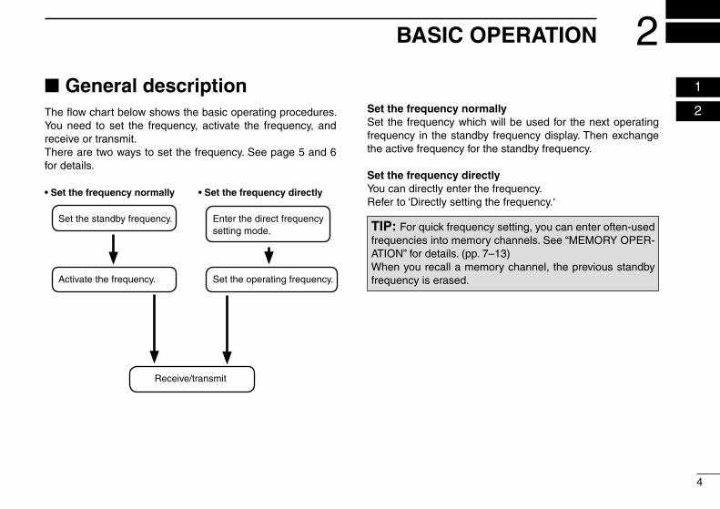
■ General descriptionThe flow chart below shows the basic operating procedures. You need to set the frequency, activate the frequency, and receive or transmit. There are two ways to set the frequency. See page 5 and 6 for details.
• Set the frequency normally • Set the frequency directly
Set the frequency normallySet the frequency which will be used for the next operating frequency in the standby frequency display. Then exchange the active frequency for the standby frequency.
Set the frequency directlyYou can directly enter the frequency.Refer to ‘Directly setting the frequency.‘
TIP: For quick frequency setting, you can enter often-used frequencies into memory channels. See “MEMORY OPER-ATION” for details. (pp. 7–13)When you recall a memory channel, the previous standby frequency is erased.
Set the standby frequency.
Activate the frequency.
Enter the direct frequency setting mode.
Set the operating frequency.
Receive/transmit
5
2 BASIC OPERATION
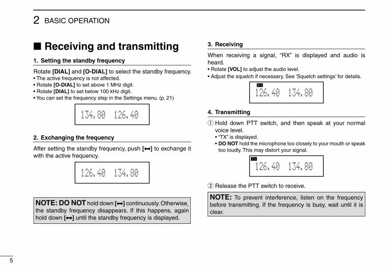
■ Receiving and transmitting1. Setting the standby frequency
Rotate [DIAL] and [O-DIAL] to select the standby frequency.• The active frequency is not affected.• Rotate [O-DIAL] to set above 1 MHz digit.• Rotate [DIAL] to set below 100 kHz digit.• You can set the frequency step in the Settings menu. (p. 21)
126.405134.80MEMORY
2. Exchanging the frequency
After setting the standby frequency, push [ ] to exchange it with the active frequency.
134.805126.40
3. Receiving
When receiving a signal, “RX” is displayed and audio is heard.• Rotate [VOL] to adjust the audio level.• Adjust the squelch if necessary. See ‘Squelch settings’ for details.
134.805126.40RX
4. Transmitting
q Hold down PTT switch, and then speak at your normal voice level.
• “TX” is displayed. • DO NOT hold the microphone too closely to your mouth or speak
too loudly. This may distort your signal.
134.805126.40TX
w Release the PTT switch to receive.
NOTE: To prevent interference, listen on the frequency before transmitting. If the frequency is busy, wait until it is clear.
NOTE: DO NOT hold down [ ] continuously. Otherwise, the standby frequency disappears. If this happens, again hold down [ ] until the standby frequency is displayed.
6
2BASIC OPERATION
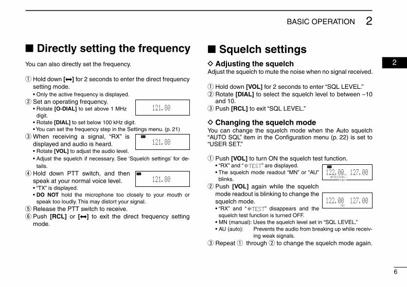
02You can also directly set the frequency.
q Hold down [ ] for 2 seconds to enter the direct frequency setting mode.
• Only the active frequency is displayed. w Set an operating frequency.
• Rotate [O-DIAL] to set above 1 MHz digit.
• Rotate [DIAL] to set below 100 kHz digit. • You can set the frequency step in the Settings menu. (p. 21)
e When receiving a signal, “RX” is displayed and audio is heard.
• Rotate [VOL] to adjust the audio level. • Adjust the squelch if necessary. See ‘Squelch settings’ for de-
tails. r Hold down PTT switch, and then speak at your normal voice level.
• “TX” is displayed. • DO NOT hold the microphone too closely to your mouth or
speak too loudly. This may distort your signal. t Release the PTT switch to receive. y Push [RCL] or [ ] to exit the direct frequency setting mode.
■ Directly setting the frequency ■ Squelch settings D Adjusting the squelch
Adjust the squelch to mute the noise when no signal received.
q Hold down [VOL] for 2 seconds to enter “SQL LEVEL.” w Rotate [DIAL] to select the squelch level to between –10 and 10. e Push [RCL] to exit “SQL LEVEL.”
D Changing the squelch modeYou can change the squelch mode when the Auto squelch “AUTO SQL” item in the Configuration menu (p. 22) is set to “USER SET.”
q Push [VOL] to turn ON the squelch test function. • “RX” and “ TEST” are displayed. • The squelch mode readout “MN” or “AU”
blinks. w Push [VOL] again while the squelch mode readout is blinking to change the squelch mode.
• “RX” and “ TEST” disappears and the squelch test function is turned OFF.
• MN (manual): Uses the squelch level set in “SQL LEVEL.” • AU (auto): Prevents the audio from breaking up while receiv-
ing weak signals. e Repeat q through w to change the squelch mode again.
121.80
121.80RX
121.80TX 127.005122.00
RX MEMORY
TESTMN
127.005122.00MEMORY
AU
7
3 MEMORY OPERATION
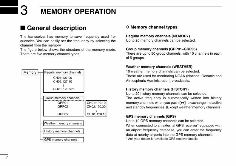
■ General descriptionThe transceiver has memory to save frequently used fre-quencies. You can easily set the frequency by selecting the channel from the memory.The figure below shows the structure of the memory mode. There are five memory channel types.
Regular memory channels
CH01:127.00CH02:127.10
CH20: 128.575
Group memory channels
CH01:120.10CH02:120.20
CH10: 130.10
Weather memory channels
History memory channels
GPS memory channels
GRP01GRP02
GRP05
… …
…
Memory
D Memory channel types
Regular memory channels (MEMORY)Up to 20 memory channels can be selected.
Group memory channels (GRP01–GRP05)There are up to 50 group channels, with 10 channels in each of 5 groups.
Weather memory channels (WEATHER)10 weather memory channels can be selected.These are used for monitoring NOAA (National Oceanic and Atmospheric Administration) broadcasts.
History memory channels (HISTORY)Up to 20 history memory channels can be selected.The active frequency is automatically written into history memory channels when you push [ ] to exchange the active and standby frequencies. (Except weather memory channels)
GPS memory channels (GPS)Up to 10 GPS memory channels can be selected.When connected to an external GPS receiver* equipped with an airport frequency database, you can enter the frequency data at nearby airports into the GPS memory channels.* Ask your dealer for available GPS receiver details.
8
3MEMORY OPERATION
03
■ Basic operation ■ Editing Regular memory/Group memory channels
D Memory mode menuThere are memory mode menus to edit the memory contents. They contain the following items.
REPLACE (p. 9)Enter the selected memory channel frequency to the standby frequency.
DELETE (p. 9)Deletes the selected memory channel frequency.
REVIVEReturns the selected memory channel to its previous state.
CH NAME (For only regular memory channel)Sets the channel name to the selected regular memory chan-nel.
GRP NAME (For only group memory channel)Sets the group name to the selected memory group.
CH TAG (For only group memory channel)Sets the channel tag to the selected memory channel. (Se-lecting the group memory channel is the only option.)
DONEReturns to the memory mode.
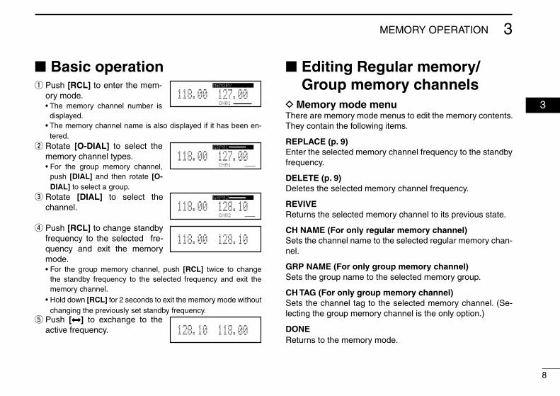
q Push [RCL] to enter the mem-ory mode.
• The memory channel number is displayed.
• The memory channel name is also displayed if it has been en-tered.
w Rotate [O-DIAL] to select the memory channel types.
• For the group memory channel, push [DIAL] and then rotate [O-DIAL] to select a group.
e Rotate [DIAL] to select the channel.
r Push [RCL] to change standby frequency to the selected fre-quency and exit the memory mode.
• For the group memory channel, push [RCL] twice to change the standby frequency to the selected frequency and exit the memory channel.
• Hold down [RCL] for 2 seconds to exit the memory mode without changing the previously set standby frequency.
t Push [ ] to exchange to the active frequency.
CH01
127.005118.00GRP01
CH02
128.105118.00GRP02
128.105118.00
118.005128.10
CH01
127.005118.00MEMORY
9
3 MEMORY OPERATION
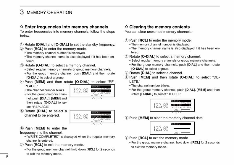
D Clearing the memory contents You can clear unwanted memory channels.
q Push [RCL] to enter the memory mode. • The memory channel number is displayed. • The memory channel name is also displayed if it has been en-
tered. w Rotate [O-DIAL] to select a memory channel.
• Select regular memory channels or group memory channels. • For the group memory channels, push [DIAL] and then rotate
[O-DIAL] to select a group. e Rotate [DIAL] to select a channel. r Push [MEM] and then rotate [O-DIAL] to select “DE-LETE.”
• The channel number blinks. • For the group memory channel, push [DIAL], [MEM] and then
rotate [O-DIAL] to select “DELETE.”
CH01
127.000
127.000122.00MEMORY
ÅDELETE Ç
t Push [MEM] to clear the memory channel data.
CH01
122.00MEMORY
y Push [RCL] to exit the memory mode. • For the group memory channel, hold down [RCL] for 2 seconds
to exit the memory mode.
D Enter frequencies into memory channelsTo enter frequencies into memory channels, follow the steps below.
q Rotate [DIAL] and [O-DIAL] to set the standby frequency. w Push [RCL] to enter the memory mode.
• The memory channel number is displayed. • The memory channel name is also displayed if it has been en-
tered. e Rotate [O-DIAL] to select a memory channel.
• Select regular memory channels or group memory channels. • For the group memory channel, push [DIAL] and then rotate
[O-DIAL] to select a group. r Push [MEM] and then rotate [O-DIAL] to select “RE-PLACE.”
• The channel number blinks. • For the group memory chan-
nel, push [DIAL], [MEM] and then rotate [O-DIAL] to se-lect “REPLACE.”
t Rotate [DIAL] to select a channel to be entered.
y Push [MEM] to enter the frequency into the channel. • “WRITE COMPLETED” is displayed when the regular memory
channel is entered. u Push [RCL] to exit the memory mode.
• For the group memory channel, hold down [RCL] for 2 seconds to exit the memory mode.
CH01
128.000
127.000122.00MEMORY
REPLACE Ç
CH02
128.000
127.000122.00MEMORY
REPLACE Ç
10
3MEMORY OPERATION
03
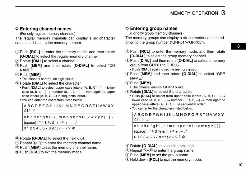
D Entering channel names (For only regular memory channels)
The regular memory channels can display a six character name in addition to the memory number.
q Push [RCL] to enter the memory mode, and then rotate [O-DIAL] to select the regular memory channel. w Rotate [DIAL] to select a channel. e Push [MEM] and then rotate [O-DIAL] to select “CH NAME.” r Push [MEM].
• The channel name’s 1st digit blinks. t Rotate [DIAL] to select the character.
• Push [DIAL] to select upper case letters (A, B, C, ···) → lower case (a, b, c, ···) → number (0, 1, 2, ···) → then again to upper case letters (A, B, C, ···) in sequential order.
• You can enter the characters listed below.
y Rotate [O-DIAL] to select the next digit. u Repeat t–y to enter the memory channel name. i Push [MEM] to set the memory channel name. o Push [RCL] to exit the memory mode.
D Entering group names (For only group memory channels)
The memory groups can display a six character name in ad-dition to the group number (“GRP01”–“GRP05”).
q Push [RCL] to enter the memory mode, and then rotate [O-DIAL] to select the group memory channel. w Push [DIAL] and then rotate [O-DIAL] to select a memory group from GRP01 to GRP05.
• Push [DIAL] again to set the memory group. e Push [MEM] and then rotate [O-DIAL] to select “GRP NAME.” r Push [MEM].
• The channel name’s 1st digit blinks. t Rotate [DIAL] to select the character.
• Push [DIAL] to select from upper case letters (A, B, C, ···) → lower case (a, b, c, ···) → number (0, 1, 2, ···) → then again to upper case letters (A, B, C, ···) in sequential order.
• You can enter the characters listed below.
y Rotate [O-DIAL] to select the next digit. u Repeat t–y to enter the group name. i Push [MEM] to set the group name. o Hold down [RCL] to exit the memory mode.
A B C D E F G H I J K L M N O P Q R S T U V W X Y Z [ \ ] ^ _ `
a b c d e f g h i j k l m n o p q r s t u v w x y z { | } ~
(space) ! ” # $ % & ’ ( ) ∗ + , – . /
0 1 2 3 4 5 6 7 8 9 : ; < = > ? @
A B C D E F G H I J K L M N O P Q R S T U V W X Y Z [ \ ] ^ _ `
a b c d e f g h i j k l m n o p q r s t u v w x y z { | } ~
(space) ! ” # $ % & ’ ( ) ∗ + , – . /
0 1 2 3 4 5 6 7 8 9 : ; < = > ? @
11
3 MEMORY OPERATION
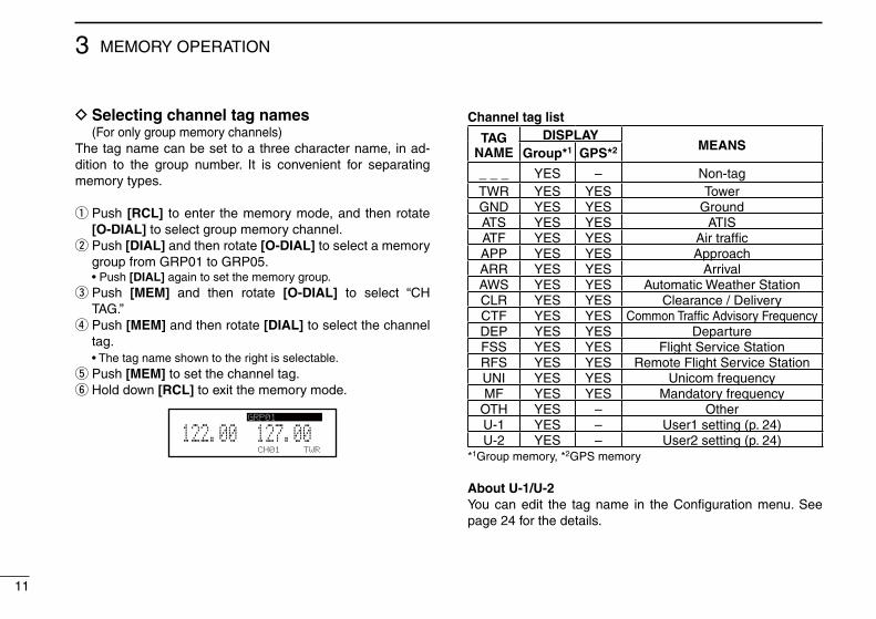
D Selecting channel tag names (For only group memory channels)
The tag name can be set to a three character name, in ad-dition to the group number. It is convenient for separating memory types.
q Push [RCL] to enter the memory mode, and then rotate [O-DIAL] to select group memory channel. w Push [DIAL] and then rotate [O-DIAL] to select a memory group from GRP01 to GRP05.
• Push [DIAL] again to set the memory group. e Push [MEM] and then rotate [O-DIAL] to select “CH TAG.” r Push [MEM] and then rotate [DIAL] to select the channel tag.
• The tag name shown to the right is selectable. t Push [MEM] to set the channel tag. y Hold down [RCL] to exit the memory mode.
CH01
127.005122.00GRP01
TWR
Channel tag list
TAG NAME
DISPLAYMEANSGroup*1 GPS*2
_ _ _ YES – Non-tagTWR YES YES TowerGND YES YES GroundATS YES YES ATISATF YES YES Air trafficAPP YES YES ApproachARR YES YES ArrivalAWS YES YES Automatic Weather StationCLR YES YES Clearance / DeliveryCTF YES YES Common Traffic Advisory FrequencyDEP YES YES DepartureFSS YES YES Flight Service StationRFS YES YES Remote Flight Service StationUNI YES YES Unicom frequencyMF YES YES Mandatory frequency
OTH YES – OtherU-1 YES – User1 setting (p. 24)U-2 YES – User2 setting (p. 24)
*1Group memory, *2GPS memory
About U-1/U-2You can edit the tag name in the Configuration menu. See page 24 for the details.
12
3MEMORY OPERATION
03
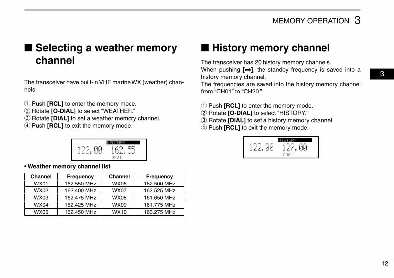
■ Selecting a weather memory channel
The transceiver have built-in VHF marine WX (weather) chan-nels.
q Push [RCL] to enter the memory mode. w Rotate [O-DIAL] to select “WEATHER.” e Rotate [DIAL] to set a weather memory channel. r Push [RCL] to exit the memory mode.
WX01
162.555122.00DUAL WEATHER
• Weather memory channel list
Channel Frequency Channel FrequencyWX01 162.550 MHz WX06 162.500 MHzWX02 162.400 MHz WX07 162.525 MHzWX03 162.475 MHz WX08 161.650 MHzWX04 162.425 MHz WX09 161.775 MHzWX05 162.450 MHz WX10 163.275 MHz
■ History memory channelThe transceiver has 20 history memory channels.When pushing [ ], the standby frequency is saved into a history memory channel.The frequencies are saved into the history memory channel from “CH01” to “CH20.”
q Push [RCL] to enter the memory mode. w Rotate [O-DIAL] to select “HISTORY.” e Rotate [DIAL] to set a history memory channel. r Push [RCL] to exit the memory mode.
CH01
127.005122.00HISTORY
13
3 MEMORY OPERATION
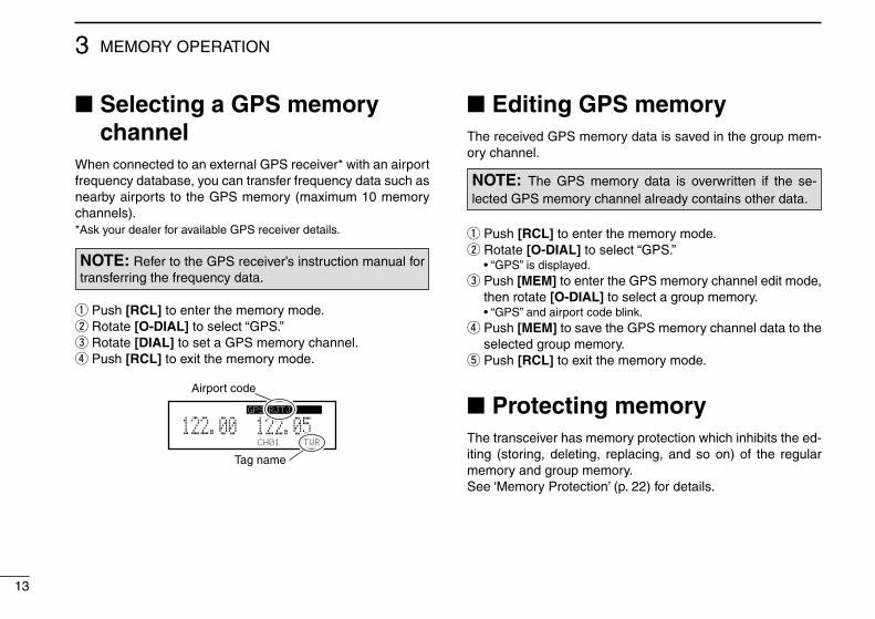
■ Selecting a GPS memory channel
When connected to an external GPS receiver* with an airport frequency database, you can transfer frequency data such as nearby airports to the GPS memory (maximum 10 memory channels).*Ask your dealer for available GPS receiver details.
q Push [RCL] to enter the memory mode. w Rotate [O-DIAL] to select “GPS.” e Rotate [DIAL] to set a GPS memory channel. r Push [RCL] to exit the memory mode.
CH01 TWR
122.055122.00GPS RJTJ
Airport code
Tag name
NOTE: Refer to the GPS receiver’s instruction manual for transferring the frequency data.
■ Editing GPS memoryThe received GPS memory data is saved in the group mem-ory channel.
q Push [RCL] to enter the memory mode. w Rotate [O-DIAL] to select “GPS.”
• “GPS” is displayed. e Push [MEM] to enter the GPS memory channel edit mode, then rotate [O-DIAL] to select a group memory.
• “GPS” and airport code blink. r Push [MEM] to save the GPS memory channel data to the selected group memory. t Push [RCL] to exit the memory mode.
■ Protecting memoryThe transceiver has memory protection which inhibits the ed-iting (storing, deleting, replacing, and so on) of the regular memory and group memory.See ‘Memory Protection’ (p. 22) for details.
NOTE: The GPS memory data is overwritten if the se-lected GPS memory channel already contains other data.
14
4OTHER FUNCTIONS
03
04
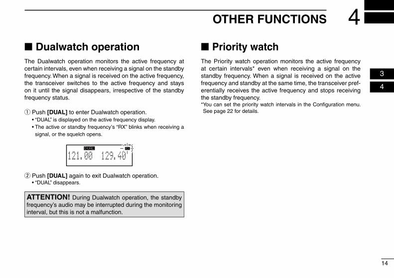
■ Dualwatch operationThe Dualwatch operation monitors the active frequency at certain intervals, even when receiving a signal on the standby frequency. When a signal is received on the active frequency, the transceiver switches to the active frequency and stays on it until the signal disappears, irrespective of the standby frequency status.
q Push [DUAL] to enter Dualwatch operation. • “DUAL” is displayed on the active frequency display. • The active or standby frequency’s “RX” blinks when receiving a
signal, or the squelch opens.
w Push [DUAL] again to exit Dualwatch operation. • “DUAL” disappears.
■ Priority watchThe Priority watch operation monitors the active frequency at certain intervals* even when receiving a signal on the standby frequency. When a signal is received on the active frequency and standby at the same time, the transceiver pref-erentially receives the active frequency and stops receiving the standby frequency. * You can set the priority watch intervals in the Configuration menu. See page 22 for details.
ATTENTION! During Dualwatch operation, the standby frequency’s audio may be interrupted during the monitoring interval, but this is not a malfunction.
129.405121.00RX DUAL RX
15
4 OTHER FUNCTIONS
■ Using the lock functionThe lock function prevents accidental frequency changes and accidental function activation. There are two lock modes, panel lock and dial lock. You can select the lock mode in the Settings menu. See page 20 for details.Panel lock: Lock transceiver’s keys and dials except [EC] and
[VOL].Dial lock: Lock [DIAL] and [O-DIAL].
q Hold down [DIAL] for 2 seconds to turn ON the lock func-tion.
• “
O F
D” is displayed when dial lock mode is selected. • “
O F
P” is displayed when panel lock mode is selected.
w Push [DIAL] to turn OFF the lock function. • “
O F
D” or “
O F
P” disappears.
■ Accessing the 121.5 MHz emergency frequency
The transceiver can be set to the 121.5 MHz emergency fre-quency immediately. This function can be activated even if the key lock function is in use.
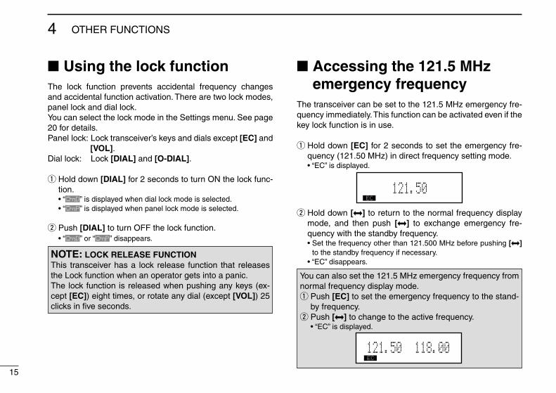
q Hold down [EC] for 2 seconds to set the emergency fre-quency (121.50 MHz) in direct frequency setting mode.
• “EC” is displayed.
121.505EC
w Hold down [ ] to return to the normal frequency display mode, and then push [ ] to exchange emergency fre-quency with the standby frequency.
• Set the frequency other than 121.500 MHz before pushing [ ] to the standby frequency if necessary.
• “EC” disappears.
NOTE: LOCK RELEASE FUNCTIONThis transceiver has a lock release function that releases the Lock function when an operator gets into a panic.The lock function is released when pushing any keys (ex-cept [EC]) eight times, or rotate any dial (except [VOL]) 25 clicks in five seconds.
You can also set the 121.5 MHz emergency frequency from normal frequency display mode.
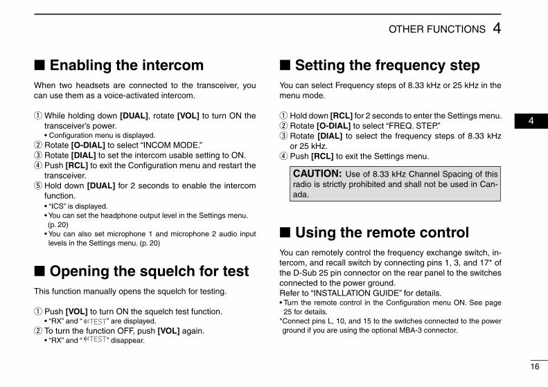
q Push [EC] to set the emergency frequency to the stand-by frequency. w Push [ ] to change to the active frequency.
• “EC” is displayed.
121.50 118.00EC
16
4OTHER FUNCTIONS
04
■ Enabling the intercomWhen two headsets are connected to the transceiver, you can use them as a voice-activated intercom.
q While holding down [DUAL], rotate [VOL] to turn ON the transceiver’s power.
• Configuration menu is displayed. w Rotate [O-DIAL] to select “INCOM MODE.” e Rotate [DIAL] to set the intercom usable setting to ON. r Push [RCL] to exit the Configuration menu and restart the transceiver. t Hold down [DUAL] for 2 seconds to enable the intercom function.
• “ICS” is displayed. • You can set the headphone output level in the Settings menu. (p. 20) • You can also set microphone 1 and microphone 2 audio input
levels in the Settings menu. (p. 20)
■ Opening the squelch for testThis function manually opens the squelch for testing.
q Push [VOL] to turn ON the squelch test function. • “RX” and “ TEST” are displayed.
w To turn the function OFF, push [VOL] again. • “RX” and “ TEST” disappear.
■ Setting the frequency stepYou can select Frequency steps of 8.33 kHz or 25 kHz in the menu mode.
q Hold down [RCL] for 2 seconds to enter the Settings menu. w Rotate [O-DIAL] to select “FREQ. STEP.” e Rotate [DIAL] to select the frequency steps of 8.33 kHz or 25 kHz. r Push [RCL] to exit the Settings menu.
CAUTION: Use of 8.33 kHz Channel Spacing of this
radio is strictly prohibited and shall not be used in Can-ada.
■ Using the remote controlYou can remotely control the frequency exchange switch, in-tercom, and recall switch by connecting pins 1, 3, and 17* of the D-Sub 25 pin connector on the rear panel to the switches connected to the power ground.Refer to “INSTALLATION GUIDE” for details.• Turn the remote control in the Configuration menu ON. See page
25 for details. * Connect pins L, 10, and 15 to the switches connected to the power ground if you are using the optional MBA-3 connector.
17
4 OTHER FUNCTIONS
Scanning automatically searches for weather channel sig-nals.Repeatedly scans all weather memory channels. You can set the interval time (scan speed) for the scan in the Settings menu. See page 22 for details.
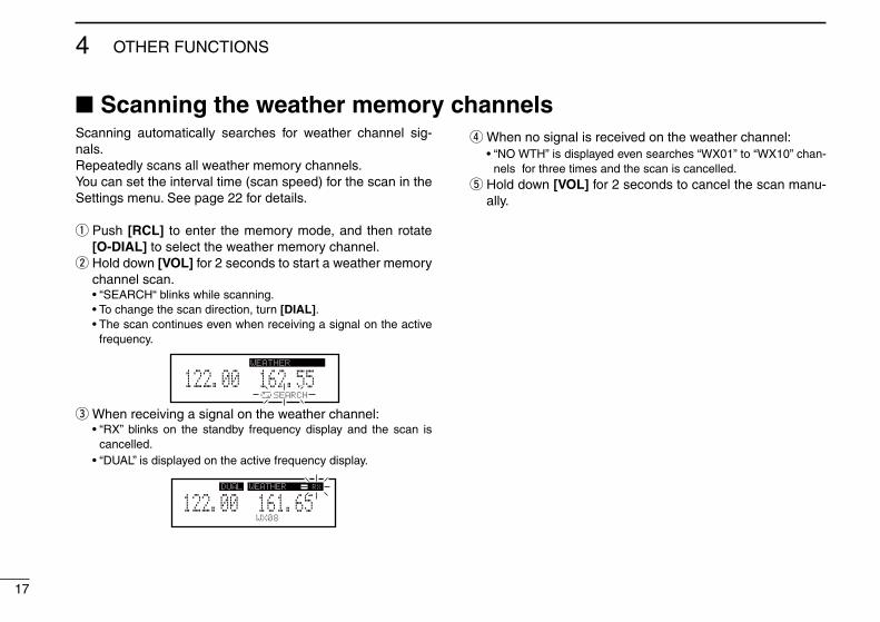
q Push [RCL] to enter the memory mode, and then rotate [O-DIAL] to select the weather memory channel. w Hold down [VOL] for 2 seconds to start a weather memory channel scan.
• “SEARCH“ blinks while scanning. • To change the scan direction, turn [DIAL]. • The scan continues even when receiving a signal on the active
frequency.
162.555122.00RX WEATHER
SEARCH
e When receiving a signal on the weather channel: • “RX” blinks on the standby frequency display and the scan is
cancelled. • “DUAL” is displayed on the active frequency display.
WEATHER
161.655122.00RX DUAL RX
WX08
r When no signal is received on the weather channel: • “NO WTH” is displayed even searches “WX01” to “WX10” chan-
nels for three times and the scan is cancelled. t Hold down [VOL] for 2 seconds to cancel the scan manu-ally.
■ Scanning the weather memory channels
18
5MENU MODE
04
05
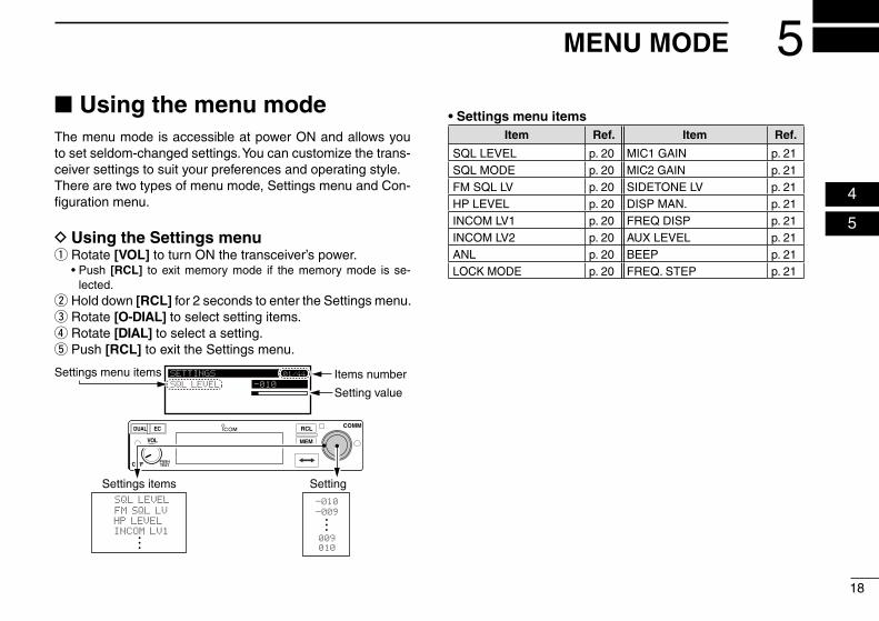
■ Using the menu modeThe menu mode is accessible at power ON and allows you to set seldom-changed settings. You can customize the trans-ceiver settings to suit your preferences and operating style.There are two types of menu mode, Settings menu and Con-figuration menu.
D Using the Settings menu q Rotate [VOL] to turn ON the transceiver’s power.
• Push [RCL] to exit memory mode if the memory mode is se-lected.
w Hold down [RCL] for 2 seconds to enter the Settings menu. e Rotate [O-DIAL] to select setting items. r Rotate [DIAL] to select a setting. t Push [RCL] to exit the Settings menu.
SETTINGS
SQL LEVEL -010
01/44
RCL
MEM
OFF
VOL
PUSHTEST
COMMDUAL EC
-010
-009
009
010
Setting
FM SQL LV
HP LEVEL
INCOM LV1
SQL LEVEL
Settings items
Settings menu items Items number
Setting value
• Settings menu itemsItem Ref. Item Ref.
SQL LEVEL p. 20 MIC1 GAIN p. 21SQL MODE p. 20 MIC2 GAIN p. 21FM SQL LV p. 20 SIDETONE LV p. 21HP LEVEL p. 20 DISP MAN. p. 21INCOM LV1 p. 20 FREQ DISP p. 21INCOM LV2 p. 20 AUX LEVEL p. 21ANL p. 20 BEEP p. 21LOCK MODE p. 20 FREQ. STEP p. 21
19
5 MENU MODE
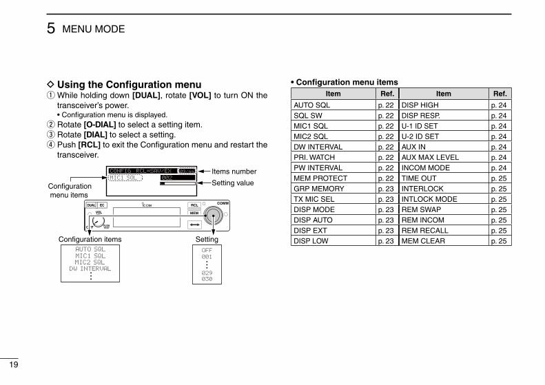
D Using the Configuration menu q While holding down [DUAL], rotate [VOL] to turn ON the transceiver’s power.
• Configuration menu is displayed. w Rotate [O-DIAL] to select a setting item. e Rotate [DIAL] to select a setting. r Push [RCL] to exit the Configuration menu and restart the transceiver.
CONFIG RCL=SAV/EX
MIC1 SQL 002
09/44
RCL
MEM
OFF
VOL
PUSHTEST
COMMDUAL EC
OFF
001
029
030
Setting
MIC1 SQL
MIC2 SQL
DW INTERVAL
AUTO SQL
Configuration items
Configuration menu items
Items number
Setting value
• Configuration menu itemsItem Ref. Item Ref.
AUTO SQL p. 22 DISP HIGH p. 24SQL SW p. 22 DISP RESP. p. 24MIC1 SQL p. 22 U-1 ID SET p. 24MIC2 SQL p. 22 U-2 ID SET p. 24DW INTERVAL p. 22 AUX IN p. 24PRI. WATCH p. 22 AUX MAX LEVEL p. 24PW INTERVAL p. 22 INCOM MODE p. 24MEM PROTECT p. 22 TIME OUT p. 25GRP MEMORY p. 23 INTERLOCK p. 25TX MIC SEL p. 23 INTLOCK MODE p. 25DISP MODE p. 23 REM SWAP p. 25DISP AUTO p. 23 REM INCOM p. 25DISP EXT p. 23 REM RECALL p. 25DISP LOW p. 23 MEM CLEAR p. 25
20
5MENU MODE
05
■ Settings menu items D AM squelch level “SQL LEVEL”
Adjust the squelch level for AM mode operation.In order to receive signals properly, the squelch must be ad-justed to the proper level.• –010 to 010: Sets the AM squelch level to between –10 and 10.
D Squelch mode “SQL MODE”Sets the squelch mode for AM mode operation*.* Displayed only when the Auto squelch “AUTO SQL” item in the Con-figuration menu (p. 22) is set to “USER SET.”
• MN (manual): Use “SQL LEVEL” to set the squelch level.• AU (auto): Prevents the audio from breaking up while receiving
weak signals.
D FM squelch level “FM SQL LV”Set the squelch level for FM mode operation.• –010 to 010: Sets the FM squelch level to between –10 and 10.
D Headphone level “HP LEVEL”Sets the headphone output level while receiving.• AF gain: The output level is the same as [VOL].• OFF (0): Mutes the headphone.• 001 to 080: Sets the audio level to between 1 and 80.
D Intercom 1 microphone audio input level “IN-COM LV1”
Sets the intercom 1 microphone input level.• OFF (0): Mutes the intercom1 microphone.• 001 to 080: Sets the intercom1 input level to between 1 and 80.
D Intercom 2 microphone audio Input level “IN-COM LV2”
Sets the intercom 2 microphone input level.• OFF (0): Mutes the intercom 2 microphone.• 001 to 080: Sets the intercom 2 input level to between 1 and 80.
D Automatic noise limiter “ANL”The ANL (Automatic Noise Limiter) function reduces noise components while receiving, such as those caused by engine ignition systems.• OFF: ANL function is OFF.• ON: ANL function is ON.
D Lock mode “LOCK MODE”Sets the lock function.• OFF : The lock function is OFF.• DIAL: The lock function applies to [DIAL].• PANEL: The lock function applies to switches on the front panel.
21
5 MENU MODE
D Setting microphone 1 Gain “MIC1 GAIN”Sets microphone 1’s gain.• –010 to 010: Sets the microphone 1’s gain to between –10 and
10.
D Setting microphone 2 Gain “MIC2 GAIN”Sets microphone 2’s gain.• –010 to 010: Sets the microphone 2’s gain to between –10 and
10.
D Sidetone level “SIDETONE LV”When using an optional headset (user supplied) through an adapter, the transceiver sends your transmitted voice to the headset for monitoring.*Ask your dealer in details.• OFF (0): The sidetone function is OFF.• 001 to 080: Sets the sidetone level to between 1 and 80.
D Manual dimmer control “DISP MAN.”Sets the brightness manually to suit your own preferences.• OFF: The display brightness is set to the minimum. The
key backlight is OFF.• 001 to 100: Sets the dimmer level to between 1 and 100.
D Frequency display “FREQ DISP”Sets the 1 kHz digit frequency displaying on the OLED.• OFF : The 1 kHz digit is not displayed on the OLED.• ON : The 1 kHz digit is always displayed on the OLED.• ZERO SUPP.: The 1 kHz digit is displayed only when the 1 kHz digit
frequency is 5 kHz.
D External input level “AUX LEVEL”Sets the external input level.* Displayed only when the External input “AUX IN” item in the Configu-ration menu (p. 24) is set to “ON” or “INCOM.”
• OFF (0): The external input is disabled.• 001 to 080: Sets the external input level to between 1 and 80.• AF GAIN: Interlocked with [VOL].
D Beep tone level “BEEP”Confirmation beep tones normally sound when storing mem-ory, operating the time-out-timer function, and so on. These can be set at a beep level.• OFF (0): The beep tone is OFF.• 001 to 100: Sets the beep tone level to between 1 and 100.
NOTE: When using an external speaker, the beep tone level while the squelch is closed is fixed and cannot be changed in the Settings menu.
D Frequency step “FREQ. STEP”Sets the frequency step: 8.33 kHz or 25 kHz.• 25kHz: Sets the frequency step to 25 kHz.• 8.33kHz: Sets the frequency step to 8.33 kHz.
CAUTION: Use of 8.33 kHz Channel Spacing of this ra-dio is strictly prohibited and shall not be used in Canada.
22
5MENU MODE
05
■ Configuration menu items D Auto squelch “AUTO SQL”
Sets the Auto squelch function.• OFF: The Auto squelch is OFF.• ON: The Auto squelch is ON.• USER SET: Set the auto squelch in the Squelch mode “SQL MODE”
item in the Settings menu. (p.20)
D Squelch mode switch setting “SQL SW”Sets the length of time that the squelch mode readout (p. 3) blinks when you switch the squelch mode. (p. 6)* Displayed only when the Auto squelch “AUTO SQL” item in the Con-figuration menu is set to “USER SET.”
• 002 to 010: Sets the length of time that the squelch mode readout blinks to between 2 seconds and 10 seconds.
D Intercom 1 squelch level “MIC1 SQL”Sets Intercom 1’s squelch level.The setting level is required to open the squelch when speak-ing into Intercom 1.• OFF (0): Turns off Intercom 1’s squelch.• 001 to 030: Sets Intercom 1’s squelch level to between 1 and 30.
D Intercom 2 squelch level “MIC2 SQL”Set Intercom 2’s squelch level.The setting level is required to open the squelch when speak-ing into Intercom 2.• OFF (0): Turns off Intercom 2’s squelch.• 001 to 030: Sets Intercom 2’s squelch level to between 1 and 30.
D Dualwatch interval “DW INTERVAL”Sets the interval time while operating Dualwatch or weather scan.• FAST: Sets the interval to 300 milliseconds.• MID: Sets the interval to 600 milliseconds.• SLOW: Sets the interval to 2 seconds.
D Priority watch “PRI.WATCH”Sets the priority watch is enabled or not.• ON: The priority watch is ON.• OFF: The priority watch is OFF.
D Priority watch interval “PW INTERVAL”Sets the active frequency receive interval time while receiving the standby frequency.• FAST: Sets the interval to 400 milliseconds.• MID: Sets the interval to 800 milliseconds.• SLOW: Sets the interval to 2 seconds.
D Memory protection “MEM PROTECT”Sets the memory protection to regular memory channels and group memory channels.Editing the regular memory and group memory channels is inhibited while the protection is ON.• OFF: The memory protection is OFF.• ON: The memory protection is ON.
23
5 MENU MODE
D Group memory channel display “GRP MEMORY”
Select whether the label is displayed or not.• CH: Only the memory channel number is displayed.• LABEL: The label is also displayed.
D Transmitting microphone selection “TX MIC SEL”
Sets the active microphone when pushing microphone’s PTT switch.The item allows you to control which connected microphone is permitted to transmit.• MIC1: Selects microphone 1.• MIC2: Selects microphone 2.• MIC1+2: Selects both microphone 1 and microphone 2.
D Dimmer mode “DISP MODE”The dimmer function dims function display and key illumina-tion brightness. You can select a dimmer functioning mode to suits your preference. • OFF: The dimmer function is OFF.• AUTO: Automatically sets the dimmer according to the current
lighting condition.• MANUAL: Manually sets the dimmer in the Manual dimmer control
“DISP MAN” item. (p. 21)
D Dimmer auto mode “DISP AUTO”Sets the method to automatically control the dimmer bright-ness.** Displayed only when the Dimmer mode “DISP MODE” item in the Configuration menu is set to “AUTO.”
• PHOTO: Controls the dimmer brightness by using the light sen-sitive detector. (p. 2)
• EXT: Controls the dimmer brightness by using an external voltage.
D External dimmer control “DISP EXT”Sets the maximum voltage for the external voltage dimmer control.* Displayed only when the Dimmer auto mode “DISP AUTO” item in the Configuration menu is set to “EXT.”
• 14VDC: The maximum external voltage is 14 V DC.• 28VDC: The maximum external voltage is 28 V DC.
D Dimmer brightness (Low) “DISP LOW”Sets the minimum brightness level in the automatic adjust-ment range.** Displayed only when the Dimmer mode “DISP MODE” item in the Configuration menu is set to “AUTO.”
• OFF : Turn OFF the minimum dimmer brightness setting.• 001 to 049: Sets the minimum dimmer brightness level to between
1 and 49.
24
5MENU MODE
05
D Dimmer brightness (High) “DISP HIGH”Sets the maximum brightness level in the automatic adjust-ment range.** Displayed only when the Dimmer mode “DISP MODE” item in the Configuration menu is set to “AUTO.”
• 050 to 100: Sets the maximum dimmer brightness level to be-tween 50 and 100.
D Dimmer response “DISP RESP.”Sets the dimmer switching speed when selecting “AUTO” in the Dimmer mode “DISP MODE” item. (p. 23)• STANDARD: Selects the normal switching speed.• FAST: Selects the fast switching speed.
D USER-1 setting/USER-2 setting “U-1 ID SET”/“U-2 ID SET”You can edit U-1 and U-2 channel tags (p.11) .q Push [MEM] to enter the U-1 or U-2 tag edit mode.w Rotate [DIAL] to select a character.e Rotate [O-DIAL] to select the next digit.r Repeat the steps w–e to enter the tag name. • You can set three characters for the tag name.t Push [MEM] again to save the name, and exit the edit
mode.
D External input “AUX IN”Set the audio usage input from an external audio device.Refer to ‘INSTALLATION GUIDE’ for an external audio device connection details.• OFF: The external audio is not used.• ON: The external audio is output from the connected head-
set while no signal is received.• INCOM: The external audio is output from the intercom 2’s
headset when: - The intercom function is OFF.
- While the intercom function is not used. - While an audio signal is not input into the intercom 1’s
microphone.
D External input gain “AUX MAX LVL”Sets the maximum gain for audio usage input.* Displayed only when the External input “AUX IN” item in the Configu-ration menu is set to “ON.”
• 0 dB: The maximum gain for audio usage input is 0dB.• +3 dB: The maximum gain for audio usage input is +3dB.• +6 dB: The maximum gain for audio usage input is +6dB.
D Intercom usable setting “INCOM MODE” Sets the intercom using or not.• ON: The intercom is usable.• OFF: The intercom is unusable.
25
5 MENU MODE
D Time-Out-Timer “TIME OUT”To prevent accidental prolonged transmission, the transceiver has a time-out-timer.The function inhibits continuous trans-missions longer than the set period of time.• 020 to 240: Setting time-out-timer period from 20 seconds to 240
seconds in 10 second steps.
D Interlock “INTERLOCK”If the transceiver is connected together with the other trans-ceiver, the interlock function can prevent the transceiver from receiving or transmitting while the other transceiver is trans-mitting.• ON: The interlock function is ON.• OFF: The interlock function is OFF.
D Interlock mode “INTLOCK MODE”Sets the function to be disabled by the interlock.* Displayed only when the Interlock “INTLOCK” item in the Configura-tion menu is set to “ON.”
• TX INHIBIT: Transmission is disabled.• RX MUTE: Audio output is disabled.• BOTH: Both transmission and audio output are disabled.
NOTE: The interlock mode is not displayed when the “TX/RX INTERLOCK SW” item is set to “DISABLE.”Ask your dealer for the “TX/RX INTERLOCK SW” setting details.
D Remote exchange “REM SWAP”Sets the remote control (p. 16) to use the frequency exchange switch or not.• OFF: The remote control for the frequency exchange switch
is OFF.• ON: The remote control for the frequency exchange switch
is ON.
D Remote incom “REM INCOM”Sets the remote control (p. 16) to use the intercom or not.• OFF: The remote control for the intercom is OFF.• ON: The remote control for the intercom is ON.
D Remote recall “REM RECALL”Sets the remote control (p. 16) to use the recall switch or not.• OFF: The remote control for the recall switch is OFF.• ON: The remote control for the recall switch is ON.
D Memory clear “MEM CLEAR”Select an item to be reset.After the selection, hold down [MEM] for 2 seconds to reset the selected item’s contents.• MENU: Reset the menu mode items setting to their defaults.• MEMORY: Clear the saved memories except the weather memory
channel.• ALL: Reset the menu mode items setting to their defaults
and clear the saved memories.
26
6OPTIONS
05
06
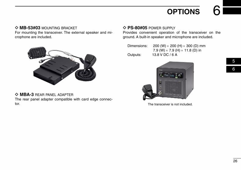
D MB-53#03 mounting bracketFor mounting the transceiver. The external speaker and mi-crophone are included.
D MBA-3 rear panel adapterThe rear panel adapter compatible with card edge connec-tor.
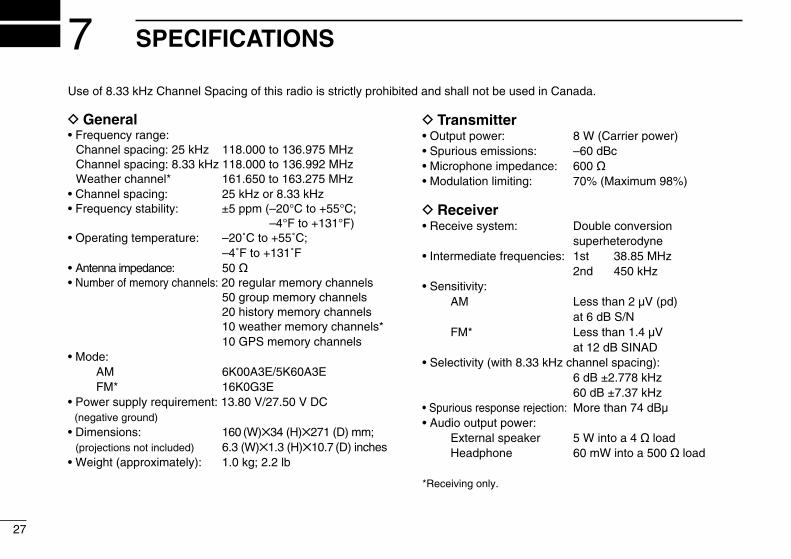
D PS-80#05 power supplyProvides convenient operation of the transceiver on the ground. A built-in speaker and microphone are included.
Dimensions: 200 (W) × 200 (H) × 300 (D) mm 7.9 (W) × 7.9 (H) × 11.8 (D) in
Outputs: 13.8 V DC / 6 A
The transceiver is not included.
27
7 SPECIFICATIONS
D General• Frequency range: Channel spacing: 25 kHz 118.000 to 136.975 MHz Channel spacing: 8.33 kHz 118.000 to 136.992 MHz Weather channel* 161.650 to 163.275 MHz• Channel spacing: 25 kHz or 8.33 kHz• Frequency stability: ±5 ppm ( –20°C to +55°C;
–4°F to +131°F)• Operating temperature: –20˚C to +55˚C; –4˚F to +131˚F• Antenna impedance: 50 ø• Number of memory channels: 20 regular memory channels 50 group memory channels 20 history memory channels 10 weather memory channels* 10 GPS memory channels• Mode: AM 6K00A3E/5K60A3E FM* 16K0G3E• Power supply requirement: 13.80 V/27.50 V DC (negative ground) • Dimensions: 160 (W)✕34 (H)✕271 (D) mm;
(projections not included) 6.3 (W)✕1.3 (H)✕10.7 (D) inches• Weight (approximately): 1.0 kg; 2.2 lb
D Transmitter• Output power: 8 W (Carrier power)• Spurious emissions: –60 dBc• Microphone impedance: 600 ø• Modulation limiting: 70% (Maximum 98%)
D Receiver• Receive system: Double conversion
superheterodyne• Intermediate frequencies: 1st 38.85 MHz
2nd 450 kHz• Sensitivity: AM Less than 2 μV (pd) at 6 dB S/N FM* Less than 1.4 μV at 12 dB SINAD• Selectivity (with 8.33 kHz channel spacing): 6 dB ±2.778 kHz 60 dB ±7.37 kHz• Spurious response rejection: More than 74 dBμ• Audio output power: External speaker 5 W into a 4 ø load Headphone 60 mW into a 500 ø load
*Receiving only.
Use of 8.33 kHz Channel Spacing of this radio is strictly prohibited and shall not be used in Canada.
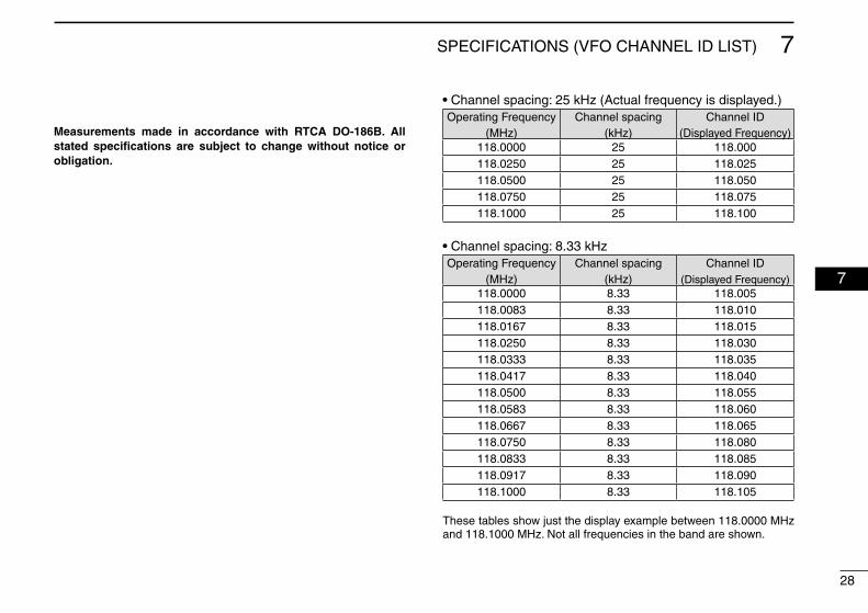
• Channel spacing: 25 kHz (Actual frequency is displayed.)Operating Frequency
(MHz)Channel spacing
(kHz)Channel ID
(Displayed Frequency)118.0000 25 118.000118.0250 25 118.025118.0500 25 118.050118.0750 25 118.075118.1000 25 118.100
• Channel spacing: 8.33 kHzOperating Frequency
(MHz)Channel spacing
(kHz)Channel ID
(Displayed Frequency)118.0000 8.33 118.005118.0083 8.33 118.010118.0167 8.33 118.015118.0250 8.33 118.030118.0333 8.33 118.035118.0417 8.33 118.040118.0500 8.33 118.055118.0583 8.33 118.060118.0667 8.33 118.065118.0750 8.33 118.080118.0833 8.33 118.085118.0917 8.33 118.090118.1000 8.33 118.105
28
7SPECIFICATIONS (VFO CHANNEL ID LIST)
7
These tables show just the display example between 118.0000 MHz and 118.1000 MHz. Not all frequencies in the band are shown.
Measurements made in accordance with RTCA DO-186B. All stated specifications are subject to change without notice or obligation.
29
INDEX
AAM squelch level .................................................................20Automatic noise limiter .......................................................20Auto squelch .......................................................................22
BBasic operation .....................................................................4Beep tone level ...................................................................21
CChannel tag ........................................................................11Clearing the memory contents .............................................9Configuration menu ............................................................19Configuration menu items ...................................................22
DDimmer auto mode .............................................................23Dimmer brightness .............................................................24Dimmer mode .....................................................................23Dimmer response ...............................................................24Directly setting the frequency ...............................................6Dualwatch ...........................................................................14Dualwatch interval ..............................................................22
EEmergency frequency .........................................................15Enter frequencies into memory channels .............................9Entering channel names .....................................................10Entering group names ........................................................10External dimmer control .....................................................23External input .....................................................................24External input gain ..............................................................24External input level .............................................................21
FFM squelch level .................................................................20Frequency display ...............................................................21Frequency step .............................................................16, 21Front panel............................................................................1Function display ....................................................................3
GGPS memory channel ........................................................13Group memory .....................................................................8Group memory channel display ..........................................23
HHeadphone level .................................................................20History memory channel .....................................................12
30
INDEX
IIntercom ..............................................................................16Intercom 1 microphone audio input level ............................20Intercom 1 squelch level .....................................................22Intercom 2 microphone audio Input level ............................20Intercom 2 squelch level .....................................................22Intercom usable setting ......................................................24Interlock ..............................................................................25Interlock mode ....................................................................25
LLock function ......................................................................15Lock mode ..........................................................................20
MManual dimmer control .......................................................21Memory clear ......................................................................25Memory operation ................................................................7Memory protection ..............................................................22Microphone 1 Gain .............................................................21Microphone 2 Gain .............................................................21
OOptions ...............................................................................26
PPriority watch ......................................................................14Priority watch interval .........................................................22Protecting memory .............................................................13
RRear panel ............................................................................2Receiving ..............................................................................5Regular memory ...................................................................8Remote control ...................................................................16Remote exchange ..............................................................25Remote incom ....................................................................25Remote recall .....................................................................25
SSettings menu items ...........................................................20Settings menu .....................................................................18Sidetone level .....................................................................21Specifications .....................................................................27Squelch settings ...................................................................6Squelch test ........................................................................16Squelch mode .....................................................................20
TTime-Out-Timer ..................................................................25Transmitting ..........................................................................5Transmitting microphone selection ...................................23
UUSER-1 setting/USER-2 setting .........................................24
WWeather memory channel ............................................12, 17

31
MEMO

32
MEMO
A-7210D-1EX-wPrinted in Japan© 2015–2017 Icom Inc.
Printed on recycled paper with soy ink. 1-1-32 Kamiminami, Hirano-ku, Osaka 547-0003, Japan