ic-m700pro instruction manual
TRANSCRIPT

INSTRUCTION MANUAL
SSB RADIO TELEPHONE
iM700PRO

ii
IMPORTANT
READ THIS INSTRUCTION MANUAL CAREFULLYbefore attempting to operate the transceiver.
SAVE THIS INSTRUCTION MANUAL—This manualcontains important safety and operating instructions forthe IC-M700PRO SSB RADIO TELEPHONE.
EXPLICIT DEFINITIONS
The explicit definitions described below apply to thisinstruction manual.
PRECAUTIONS
WORD DEFINITION
RWARNINGPersonal injury, fire hazard or electricshock may occur.
CAUTION Equipment damage may occur.
NOTEIf disregarded, inconvenience only. No riskof personal injury, fire or electric shock.
RWARNING! NEVER connect the transceiver to anAC outlet directly. This may pose a fire hazard or re-sult in an electric shock.
RWARNING! NEVER mount the transceiver over-head. The weight of the transceiver is approximately 8kg., but its apparent weight will increase several folddue to wave shocks and vibration. The transceivermust be mounted on a flat hard surface only.
NEVER connect a power source of more than 16 V DCsuch as a 24 volt battery. This connection will ruin thetransceiver.
NEVER allow children to play with equipment contain-ing a radio transmitter.
NEVER expose the transceiver to rain, snow or anyliquids.
NEVER install the IC-M700PRO into a plus-groundingship. Such a connection might blow fuses and is notusable.
DO NOT use chemical agents such as benzene or al-cohol when cleaning, as they can damage the trans-ceiver’s surfaces.
In maritime mobile operation, KEEP the transceiverand microphone as far away as possible (at least 1 m)from the magnetic navigation compass to prevent er-roneous indications.
USE an Icom microphone and/or handset only (sup-plied or optional). Other brands may have different pinassignments and may damage the transceiver.
AVOID using or placing the transceiver in areas withtemperatures below –20°C (–4°F) or above +60°C(+140°F).
AVOID connecting the transceiver to a power sourceusing reverse polarity. This connection will not onlyblow fuses but may also damage the transceiver.
AVOID placing the transceiver in excessively dusty en-vironments or in direct sunlight.
AVOID placing the transceiver against walls or puttinganything on top of the transceiver. This will obstructheat dissipation.

iii
IN CASE OF EMERGENCY (for maritime operation)
VERSIONS
Version Description
Marine2182 kHz 2-tone alarm is built-in.FSK/CW narrow filter is optional.All SSB/FSK channels available.
General2182 kHz 2-tone alarm is optional.No transmit frequency programmingallowed.
If your vessel requires assistance, contact other ves-sels and the Coast Guard by sending a distress call on2182 kHz.
The following versions are available for theIC-M700PRO.
➀ Push [2182kHz] to select the emergency fre-quency.
➁ Push [ALARM] and [TX FREQ] for 1 sec. to trans-mit a 2-tone alarm signal for at least 30 sec.• The transceiver automatically stops the alarm after 50
sec.
➂ Push [ALARM] to turn the alarm transmission off,then push and hold the PTT switch on the micro-phone and send the following information:
1. “MAYDAY, MAYDAY, MAYDAY.”
2. “THIS IS . . . . . . . . . . . . . ” (name of vessel)
3. “LOCATED AT . . . . . . . . . ” (vessel’s position)
4. Give the reason for the distress call.
5. Explain what assistance you need.
6. Give additional information:• Vessel type• Vessel length• Vessel color• Number of people onboard.

iv
TABLE OF CONTENTS
IMPORTANT . . . . . . . . . . . . . . . . . . . . . . . . . . . . . . iiEXPLICIT DEFINITIONS . . . . iiPRECAUTIONS . . . . . . . . . . . . . . . . . . . . . . . . . . . . iiIN CASE OF EMERGENCY . . . . . . . . . . . . . . . . . . iiiVERSIONS . . . . . . . . . . . . . . . . . . . . . . . . . . . . . . . iiiTABLE OF CONTENTS . . . . . . . . . . . . . . . . . . . . . iv
1 OPERATING RULES AND GUIDELINES . . . . . . 1
2 PANEL DESCRIPTION . . . . . . . . . . . . . . . . . . 2–4 Front panel . . . . . . . . . . . . . . . . . . . . . . . . . . . . 2 Display . . . . . . . . . . . . . . . . . . . . . . . . . . . . . . . 4
3 SELECTING A CHANNEL/FREQUENCY . . . . 5–7 Memory mode/VFO mode . . . . . . . . . . . . . . . . 5 Selecting a channel . . . . . . . . . . . . . . . . . . . . . 5
D Scan function . . . . . . . . . . . . . . . . . . . . . . . . . . . . . 6 Selecting a frequency . . . . . . . . . . . . . . . . . . . . 6 Resetting the CPU . . . . . . . . . . . . . . . . . . . . . . 7
4 RECEIVE AND TRANSMIT . . . . . . . . . . . . . . 8–10 Basic voice receive and transmit . . . . . . . . . . . 8 Functions for transmit . . . . . . . . . . . . . . . . . . . . 8
D Transmit frequency check . . . . . . . . . . . . . . . . . . . 8 Functions for receive . . . . . . . . . . . . . . . . . . . . 9
D Squelch function . . . . . . . . . . . . . . . . . . . . . . . . . . 9D Noise blanker . . . . . . . . . . . . . . . . . . . . . . . . . . . . . 9D AGC off function . . . . . . . . . . . . . . . . . . . . . . . . . . . 9D Clarity control . . . . . . . . . . . . . . . . . . . . . . . . . . . . . 9
CW operation . . . . . . . . . . . . . . . . . . . . . . . . . 10 FSK operation . . . . . . . . . . . . . . . . . . . . . . . . . 10
5 SET MODE . . . . . . . . . . . . . . . . . . . . . . . . . . 11–14 Set mode operation . . . . . . . . . . . . . . . . . . . . . 11 Set mode contents . . . . . . . . . . . . . . . . . . . . . 11
6 CONNECTIONS AND INSTALLATION . . . . 15–21 Connections on rear panel . . . . . . . . . . . . . . . 15 Unpacking . . . . . . . . . . . . . . . . . . . . . . . . . . . . 15 Connector information . . . . . . . . . . . . . . . . . . 16 Ground connection . . . . . . . . . . . . . . . . . . . . . 18 Power source . . . . . . . . . . . . . . . . . . . . . . . . . 18 Antenna . . . . . . . . . . . . . . . . . . . . . . . . . . . . . 19
D MN-100/MN-101L . . . . . . . . . . . . . . . . . . . . . . . . 19D AT-130 . . . . . . . . . . . . . . . . . . . . . . . . . . . . . . . . . 19D Non-Icom tuner . . . . . . . . . . . . . . . . . . . . . . . . . . 19
Mounting . . . . . . . . . . . . . . . . . . . . . . . . . . . . . 20D Mounting location . . . . . . . . . . . . . . . . . . . . . . . . . 20D Mounting example . . . . . . . . . . . . . . . . . . . . . . . . 20D Transceiver dimensions . . . . . . . . . . . . . . . . . . . . 20
Installing internal options . . . . . . . . . . . . . . . . 21D Opening the case . . . . . . . . . . . . . . . . . . . . . . . . . 21D Installing an optional filter and alarm unit . . . . . . 21
Fuse replacement . . . . . . . . . . . . . . . . . . . . . . 21
7 TROUBLESHOOTING . . . . . . . . . . . . . . . . . . . . 22
8 SPECIFICATIONS AND OPTIONS . . . . . . . . . . 23 Specifications . . . . . . . . . . . . . . . . . . . . . . . . . 23 Options . . . . . . . . . . . . . . . . . . . . . . . . . . . . . . 23

1
1OPERATING RULES AND GUIDELINES
CALL PROCEDURESCalls must be properly identified and time limits mustbe respected.
➀ Give your call sign each time you call another vesselor coast station. If you have no call sign, identifyyour vessel name and the name of the licensee.
➁ Give your call sign at the end of each transmissionthat lasts more than 3 min.
➂ You must break and give your call sign at least onceevery 15 min. during long ship-to-shore calls.
➃ Keep your unanswered calls short, less than 30 sec.Do not repeat a call for 2 min.
➄ Unnecessary transmissions are not allowed.
PRIORITIES➀ Read all rules and regulations pertaining to priorities
and keep an up-to-date copy handy. Safety and dis-tress calls take priority over all others.
➁ False or fraudulent distress calls are prohibited andpunishable by law.
PRIVACY➀ Information overheard but not intended for you can-
not be lawfully used in any way.
➁ Indecent or profane language is prohibited.
LOGS➀ All distress, emergency and safety calls must be
recorded in complete detail. Log data activity is usu-ally recorded in 24 hour time. Universal Time (UTC)is frequently used.
➁ Adjustments, repairs, channel frequency changesand authorized modifications affecting electrical op-eration of the equipment must be kept in the main-tenance log; entries must be signed by theauthorized licensed technician performing or super-vising the work.
RADIO LICENSES(1) SHIP STATION LICENSEYou must have a current radio station license beforeusing the transceiver. It is unlawful to operate a shipstation which is not licensed.
Inquire through your dealer or the appropriate govern-ment agency for a Ship-Radiotelephone license appli-cation. This government-issued license states the callsign which is your craft’s identification for radio pur-poses.
(2) OPERATOR’S LICENSEA Restricted Radiotelephone Operator Permit is the li-cense most often held by small vessel radio operatorswhen a radio is not required for safety purposes.
The Restricted Radiotelephone Operator Permit mustbe posted or be kept with the operator. Only a licensedradio operator may operate a transceiver.
However, non-licensed individuals may talk over atransceiver if a licensed operator starts, supervises,and ends the call, and makes the necessary log en-tries.
Keep a copy of the current government rules and reg-ulations handy.

2
2 PANEL DESCRIPTION
Front panel
q MICROPHONE CONNECTOR (p. 16)Accepts the supplied microphone or an optionalhandset.
NOTE: No audio is output via the speaker when themicrophone or handset is not connected.
w POWER SWITCH [POWER]Turns power on and off.
e SPEAKER SWITCH [SPEAKER]Turns the built-in speaker on and off.• “è” appears in the display while the speaker is turned
off.• Any external speaker connected to the rear panel is not
turned off.
r DISPLAY INTENSITY SWITCH [DIMMER]Turns the display backlighting on and off.
t VOLUME CONTROL [VOLUME]Adjusts the audio output level.• Audio does not come from the speaker when: A microphone is not connected. The [SQL] switch is turned on and no signal is being
received.
y GROUP CHANNEL SELECTOR [GROUP] In memory mode, selects 1 of 3 channel groups
(“A,” “B” or “C”). (p. 5)• In VFO mode, no function.
Selects an item in set mode. (p. 11)
u ANTENNA TUNE SWITCH [TUNE] (p. 8)Tunes the connected tuner to the antenna.• Activates only when an optional antenna tuner such as
Icom’s AT-130 is connected.
NOTE: When selecting “automatic tuning” in setmode, pushing this switch is not necessary to tunethe antenna. (p. 11)
i CHANNEL SELECTOR [CHANNEL] (p. 5) In memory mode, selects an operating channel
within the selected channel group.• A maximum of 50 channels are available in each
channel group depending on set mode setting (pgs.13, 14).
In VFO mode, changes the operating frequencyin 0.1 kHz steps.• Frequencies selected in VFO mode are temporary.
o SCAN SWITCH [SCAN] (p. 6)Push to toggle scan on and off.
!0 CLARITY CONTROL [CLARITY] (p. 9)Shifts the receive frequency ±150 Hz for clear re-ception of an off frequency signal.
MICROPHONE
POWER
VOLUME
ALARM
TX FREQ
2182KHzRESET
MODE
TUNE
SSB RADIO TELEPHONE
AGC SQL SCAN
CLARITY
N B
SPEAKER
[ALARM] [TX FREQ]+
FOR ALARM TX
DIMMER
GROUP CHANNEL
1 2 3
4 5 6
7 8 9
CL
T ONLY ENT
0 CH/FREQ
iM700PRO
TUNEDUP SIMP
TX
RX
DSC FSCANSQL N B
A43210
ALM
AGCAGC
q w e r t y u i !0
!1
o
!2!3!4!5!6!7!8

3
2PANEL DESCRIPTION
!1 KEYPADNo function*.
Toggles between memory mode and VFOmode. (p. 5)• This key may be disabled by your dealer.
No function*.
No function*.
No function*.
!2 SQUELCH SWITCH [SQL] (p. 9)Activates the voice squelch function to reject unde-sired background noise while no signal is being re-ceived.• The squelch opens only when the received signal con-
tains no voice or FSK components.
!3 NOISE BLANKER SWITCH [NB] (p. 9)Turns the noise blanker function on to removepulse-type noise such as engine ignition noise.• “NB” appears when the function is turned on.
!4 AGC OFF SWITCH [AGC] (p. 9)Deactivates the AGC function to receive weak sig-nals blocked by strong adjacent signals.• “ê” appears when the [AGC] switch is turned on
(stands for AGC deactivated).
!5 MODE SWITCH [MODE]Selects an operating mode temporarily. Availablemodes differ with version.• USB, AM, J2B (AFSK), FSK, R3E and CW modes are
available.• The temporary mode is cleared and the previous mode
appears when changing a channel.
!6 TRANSMIT FREQUENCY SWITCH [TX FREQ](p. 8)
Displays the transmit frequency and opens thesquelch to check and monitor the transmit fre-quency.
!7 2182 kHz SELECTION SWITCH[2182kHz • RESET ] (p. iii) Selects channel 0 (2182 kHz; distress call fre-
quency).• The channel selector does not function when select-
ing channel 0. Ignores external control and gives the front panel
control priority when an external controller(NMEA format) is connected.
0
9to
ENT
T ONLY
CH/FREQ
CL
!8 ALARM SWITCH [ALARM] (p. iii) Emits a distress alarm signal from the speaker. Transmits a distress alarm or alarm testing signal
when pushed together with the [TX FREQ]switch.
NOTE: General versions are not equipped with this[ALARM] switch.
*These keys function in some versions. See the separateKEYPAD OPERATION and CHANNEL LIST instructionsheet for operating details.

4
2 PANEL DESCRIPTION
Display
q ALARM INDICATOR (p. iii)Appears when the alarm function is activated suchas for an alarm test or distress alarm transmission.• Not available in General version.
w RECEIVE INDICATORAppears while receiving and when the squelch isopen.
e TUNE INDICATOR (p. 8)Flashes while the connected antenna tuner, such asIcom’s AT-130, is being tuned.• Tuning starts when transmitting on a new frequency or
pushing the [TUNE] switch.
r TRANSMIT INDICATORAppears when transmitting.
t S/RF METER Shows the relative received signal strength while
receiving. Shows output power while transmitting.
y CHANNEL/VFO INDICATOR (p. 5) Shows the selected group and channel in mem-
ory mode. “FREQ” appears in VFO mode.
u SQUELCH INDICATOR (p. 9)Appears when the squelch is on.
TUNEDUP SIMP
TX
RX
SCANSQL N B
AGCAGC
ALMq
w
e
r
t y u i
o
!0
!1!2!3!4
i SCAN INDICATOR (p. 6)Appears when the scan function is in use.• The scan function is not available on some versions.• Pushing [SCAN] starts and stops scan.
o NOISE BLANKER INDICATOR (p. 9)Appears when the [NB] switch is turned on.
!0 AGC OFF INDICATOR (p. 9)Appears when the [AGC] switch is pushed to indi-cate the AGC function is deactivated.
!1 MODE READOUTShows the selected operating mode (type of emis-sion).
!2 SPEAKER OFF INDICATORAppears when the [SPEAKER] switch is pushed toindicate the front panel speaker is deactivated.
!3 FREQUENCY READOUT Shows the selected frequency whether in mem-
ory mode or VFO mode. (p. 5) Shows the transmit frequency (for duplex chan-
nels) when transmitting or when pushing [TXFREQ]. (p. 8)
!4 SIMPLEX/DUPLEX INDICATORSThese appear to show whether the selected chan-nel is simplex or duplex.• In VFO mode, only simplex channels are available.• No indicator means that there is no transmit frequency
programmed.

5
3SELECTING A CHANNEL/FREQUENCY
Memory mode/VFO modeThe transceiver has 2 operating modes: memory modeand VFO mode. Memory mode is used to select pre-programmed marine channels in one of the 3 channelgroups; VFO mode is used to select frequenciesaround preprogrammed channels.
Push [CH/FREQ] to toggle between memory and VFOmodes.• “FREQ” appears when in VFO mode.• In VFO mode only simplex operation is possible.
Selecting a channelThe transceiver has 150 channels divided into 3groups of 50 (max.) channels. However, the number ofchannels in each group can be restricted in set mode(pgs. 13, 14) depending on your needs.
NOTE: When channel 0 and/or 2182 kHz is se-lected with the [2182KHz] switch, channel selectionis NOT possible. In such cases, push [2182KHz] inadvance.
➀ Push [CH/FREQ] to select memory mode, if neces-sary.
➁ Rotate the [GROUP] selector to select the desiredchannel group; then rotate the [CHANNEL] selectorto select the desired channel.
SQL
SIMP
SQL
CH/FREQ
CH/FREQ
Memory mode
VFO mode
SQL
DUP
SQL
SIMP
SQL
Rotate[GROUP]
to select achannel group
Group A
Group B
Group C
Rotate[CHANNEL]
to select achannel withina group
Group B, channel 1
Group B, channel 2
Group B, channel 50
DUP
SQL
DUP
SQL
DUP
SQL

6
3 SELECTING A CHANNEL
D Scan functionThe scan function allows you to automatically searchchannels within a group for signals. There are 2 scantypes (selectable in set mode) as follows:
Scan operation➀ Rotate the [GROUP] selector to select the group
you wish to scan.➁ Push [SQL] to close the squelch if necessary.
• “SQL” appears.➂ Push [SCAN] to start scanning.
• “SCAN” appears.➃ Push [SCAN] again to stop scanning.
• “SCAN” disappears.
Channel scan
ch 1
ch 2 ch 3
ch 4
ch 5ch 50
scan iscancelledwhentransmitting
Channel resume scan
ch 1
ch 2 ch 3
ch 4
ch 5ch 50
scan pausesfor 10 sec. afterthe squelchopens,then resumes
Selecting a frequencyThe transceiver has 0.5 to 30.0 MHz general coveragereceive capability with 100 Hz resolution. Use VFOmode to select frequencies around the prepro-grammed channels in memory mode.
NOTE: Frequencies selected in VFO mode are fortemporary use and are not stored in memory.
➀ While in memory mode, rotate the [GROUP] and[CHANNEL] selectors to select the channel nearestthe frequency you want.
➁ Push [CH/FREQ] to select VFO mode.• “FREQ” appears.
➂ Rotate the [CHANNEL] selector to select the de-sired frequency.• Frequency changes in 100 Hz steps.
Rotate[CHANNEL]
to select afrequency in0.1 kHz steps
1.6 MHz selected
1.6001 MHz selected
SIMP
SQL
SIMP
SQL

7
3SELECTING A CHANNEL
Resetting the CPUUnder some circumstances the transceiver’s internalCPU may cause erroneous indications on the display.If this happens, reset the CPU as follows:
While pushing [ENT] + [0], push [POWER] to turnpower on.• The CPU is reset and the display at right appears.
CAUTION: Resetting the CPU returns set modecontents to their default values.
SIMPRX
Group A, channel 1 isselected after resettingthe CPU.

8
4 RECEIVE AND TRANSMIT
Basic voice receive and transmit➀ Check the following in advance:
Microphone is connected. [SPEAKER] switch is turned off. [SQL] switch is turned off. [CLARITY] control is set to the center position. Memory mode is selected.
• Push [CH/FREQ] to select memory mode, if neces-sary.
➁ Select the desired channel to be received with the[GROUP] and [CHANNEL] selectors.• When receiving a signal, the S-meter shows the signal
strength.➂ Adjust [VOLUME] to the desired audio level when
receiving a signal.➃ Push [MODE] to select the desired operating mode,
if the received signal is in a different mode.➄ Push [TUNE] to tune the antenna tuner, if con-
nected.• This operation is not necessary when “automatic tuning”
is selected in set mode (p. 11).➅ To transmit on the channel, push and hold the PTT
switch on the microphone.• “TUNE” flashes for 1 to 2 sec. for the first transmission
on a channel when an antenna tuner is connected.➆ After the flashing stops, speak into the microphone
at your normal voice level.• The RF meter shows the output power according to your
voice level.➇ Release the PTT switch to return to receive.
microphoneconnector
[SQL]
[SPEAKER] [CLARITY]
Functions for transmit
D Transmit frequency checkWhen “DUP” appears on the display such as for aship-to-shore channel, the transmit frequency differsfrom the receive frequency.
In such cases, the transmit frequency should be mon-itored before transmitting to prevent interference toother stations.
Push and hold [TX FREQ] to monitor the transmit fre-quency.
• The display shows the transmit frequency.
TX FREQ

9
4RECEIVE AND TRANSMIT
Functions for receive
D Squelch functionThe squelch function detects signals with voice com-ponents and squelches (mutes) unwanted signalssuch as unmodulated beat signals. This providesquiet standby.
When you need to receive weak signals, the squelchshould be turned off.
Push [SQL] to toggle the function on and off.
• “SQL” appears when the squelch function is turned on.
DUP
SQL
D Noise blankerThe noise blanker function reduces pulse type noisesuch as that coming from engine ignitions.
The noise blanker may distort reception of strong sig-nals. In such cases, the noise blanker should beturned off.
Push [NB] to toggle the function on and off.
• “NB” appears when the noise blanker function is turnedon.
DUPRX
N B
D AGC off functionThe receiver gain is automatically adjusted accordingto received signal strength with the AGC (AutomaticGain Control) function to prevent distortion fromstrong signals and to obtain a constant output level.
When receiving weak signals with adjacent strongsignals or noise, the AGC function may reduce thesensitivity. In this situation, the AGC function shouldbe deactivated.
Push [AGC] to toggle the function on and off.
• “ê” appears when the AGC function is deactivated.
DUPRX
AGCAGC
D Clarity controlVoice signals received from other stations may be dif-ficult to receive. This may sometimes happen if a sta-tion is transmitting slightly off frequency. In suchcases, compensate the receive frequency only, usingthe [CLARITY] control.
Adjust [CLARITY] to improve the audio signal.
[CLARITY]

10
4 RECEIVE AND TRANSMIT
CW operationThe transceiver has the following CW keying featuresselectable in set mode as described on page 12. Full break-in (receiving is possible while transmitting) Delay keying (automatic transmission with keying) Off (manual transmission is necessary before keying)
➀ Connect a CW keyer or an external electronickeyer to the ACC(1) socket as shown at right.
➁ Select the desired channel to operate CW mode.➂ When the selected channel is not in CW mode,
push [MODE] one or more times to select “CW.”➃ Operate the CW keyer to transmit a CW signal.
NOTE: CW mode is not available in some versions. CW narrow can be selected in set mode (p. 12)
when an optional filter is installed.
CW key connection
2
8
4 51 36 7
ACC(1) socket
pin 1
pin 2CW key
FSK operationThe transceiver has FSK and J2B modes for FSK op-eration—use FSK when using the built-in oscillator;use J2B when using an AFSK terminal unit.
➀ Connect an FSK terminal unit as shown at right.➁ Select the desired channel.
• FSK channels are available depending on version.➂ Push [MODE] one or more times to select the type
of emission, “FSK” or “J2B.”➃ Operate the FSK terminal unit.
NOTE: FSK shift frequency and FSK polarity can be
adjusted in set mode (p. 12). Some transceivers my operate 1.7 kHz higher
than the IC-M700PRO’s J2B mode even whenthe same displayed frequencies are in use.
FSK terminal unit connection
2
8
4 51 36 7
ACC(1) socketFSK terminal unit
FSK keying
AF input
Tx/Rx control
Ground
pin 3
pin 4
pins 2, 5

11
5SET MODE
Set mode operationSet mode operation is used for programming infre-quently changed values or conditions of functions.
NOTE: Some of the set mode items described inthis section are not available on some transceiverversions.
➀ Push [POWER] to turn power off, if necessary.➁ While pushing [ENT] + [1], push [POWER] to turn
power on and enter set mode.➂ Rotate the [GROUP] selector to select the desired
item.➃ Rotate the [CHANNEL] selector to set the values or
conditions for the selected item.➄ Turn power off and on again to exit set mode.
[POWER]
Condition
Item
[ENT][1]
(1) Connected antenna tunerThe transceiver has several tuner control systems foruse with an optional Icom antenna tuner. Select thecondition depending on the connected antenna tuner.
NOTE: Internal switch selection may be requiredwhen using a non-Icom tuner (p. 19).
AT-130(default)
AT-120
AH-3
(2) Automatic tuning conditionWhen the optional AT-130 automatic antenna tuner isconnected, tuning can be started automatically with-out the [TUNE] switch, for instant operation.
If manual tuning is required, this automatic operationcan be deactivated.
Tuning starts when pushing [PTT] on a new frequency.
Tuning starts only when [TUNE] is pushed.(default)
(3) Scan type selectionThis item sets scan to function as “channel scan” or“channel resume scan.”
Both channel scan and channel resume scan searcharound a user selected channel or search in the bandwhen a channel is selected.
Channel scanScan is canceled when transmitting.
Channel resume scanScan pauses when squelch opens, then resumes after 10 sec.(default)
Set mode contents

12
5 SET MODE
(4) Scan speedSelects scan speed as follows:
(unit: sec./ch)Faster Slower
Fastest scan speed(default)
Slowest scan speed
(5) CW/FSK narrow filterThis item selects the passband width for CW (A1A),FSK or J2B mode.
NOTE: When “on” is selected without optional fil-ter installation, the transceiver does not function inthese modes.
Passband:2.3 kHz/–6 dB(default)
Passband:500 Hz/–6 dB
(6) FSK shift frequencySeveral shift frequencies (the difference between themark and space frequency) are used for FSK opera-tion. This item allows you to select a shift frequencyfor almost any FSK system.
(7) FSK polarityNormal and reverse polarities are available for FSKoperation. This item allows you to select one of thesepolarities.
“FK-REV off” (normal):key open (mark); key close (space)
“FK-REV on” (reverse):key open (space); key close (mark)
Shift frequency:170 Hz(default)
Shift frequency:425 Hz
Shift frequency:850 Hz
FSK normal(default)
FSK reverse
(8) CW break-inThe CW break-in function (in A1A mode) togglestransmit and receive with CW keying. Full break-in al-lows you to receive signals between transmitted key-ing pulses during CW transmission. Semi break-inallows you to mute receiving until keying stops withsome delay time.
Full break-inAutomatic keying without delay time (default)
Semi break-inAutomatic keying with delay time
OFFManual transmission necessary for keying
2 3 4 5 6 7 8 9 102 3 4 5 6 7 8 9 10

13
5SET MODE
(9) LCD contrastThe LCD contrast can be adjusted through 10 levelsto suit transceiver mounting angle, location and am-bient lighting.
Lowest contrast
Highest contrast
(default: 7)
(10) ID number setting for remote controlWhen connecting an external controller such as apersonal computer, 2-digit ID codes are required toaccess the transceiver. The IC-M700PRO adoptsNMEA0183 format and uses a “proprietary sentence”for remote control.
NMEA ID: 1
NMEA ID: 99
(default: 2)
(11) Remote control input terminalRemote control signals can be input via the [RE-MOTE] socket or [CLONE] jack.
[REMOTE] socket(default)
[CLONE] jack
(12) Display backlightingAllows you to select 1 of 4 intensity levels for the dis-play backlighting.
Dimmest(default)
Brightest
(13) Group A channel inhibitThis item allow you to set the number of usable chan-nels in channel group A, up to a maximum of 50channels.
Minimum number of channels set forGroup A: 1
Maximum number of channels set forGroup A: 50 (default)

14
5 SET MODE
(14) Group B channel inhibitThis item allow you to set the number of usable chan-nels in channel group B, up to a maximum of 50channels.
Minimum number of channels set forGroup B: 1
Maximum number of channels set forGroup B: 50 (default)
(15) Group C channel inhibitThis item allow you to set the number of usable chan-nels in channel group C, up to a maximum of 50channels.
Minimum number of channels set forGroup C: 1
Maximum number of channels set forGroup C: 50 (default)

6CONNECTIONS AND INSTALLATION
15
u TUNER RECEPTACLEConnects a control cable to an optional AT-130 AN-TENNA TUNER. A female connector is supplied forconnection.
i DC POWER RECEPTACLEConnects to a regulated 12–16 V DC power sourcesuch as a 12 V battery or DC power supply usingthe supplied DC power cable.
R CAUTION: DO NOT connect to a 24 V battery.This will damage the transceiver.
o FUSE HOLDERSHold two 30 A fuses for +ve and –ve terminals. Re-place both fuses when one fuse is blown.
Connections on rear panel
q ANTENNA CONNECTOR (p. 19)Connects a 50 Ω HF band antenna with a 50 Ωmatched coaxial cable and a PL-259 plug.
w GROUND TERMINALIMPORTANT! Connects a ship’s (or vehicle’s)ground. See p. 18 for details.
e ACC(1) and ACC(2) SOCKETSSee p. 16 for details.
r CLONE JACKFor Dealer use only.
t REMOTE SOCKET (p. 17)REMOTE socket for Marine and General versions.
y EXTERNAL SPEAKER JACKConnects a 4–16 Ω external speaker using a 1⁄4"monaural plug. This external audio is not muted bythe [SPEAKER] switch on the front panel.
Optional AT-130
Externalspeaker
12 V battery
q
wr t y
u
i
oe
UnpackingMicrophone (EM-101) . . . . . . . . . . . . . . . . . . . . . . 1Microphone hanger . . . . . . . . . . . . . . . . . . . . . . . . 1DC power cable (OPC-568) . . . . . . . . . . . . . . . . . 1Mounting bracket . . . . . . . . . . . . . . . . . . . . . . . . . . 1Bracket knobs (8820000170) . . . . . . . . . . . . . . . . 4
CONNECTORSDIN connector (8-pin for ACC1) . . . . . . . . . . . . . . 1DIN connector (7-pin for ACC2) . . . . . . . . . . . . . . 1Speaker plug (5610000040) . . . . . . . . . . . . . . . . . 1Tuner connector (56100000150) . . . . . . . . . . . . . . 1Pins for tuner connector (6510019030) . . . . . . . . . 4
NUTS AND BOLTSAllen bolt (M6 × 50) . . . . . . . . . . . . . . . . . . . . . . . . 4Self-tapping screws (M6 × 30) . . . . . . . . . . . . . . . . 4Nuts (M6; use 2 pcs. for each bolt) . . . . . . . . . . . . 8Flat washers (M6) . . . . . . . . . . . . . . . . . . . . . . . . . 8Spring washers (M6) . . . . . . . . . . . . . . . . . . . . . . . 4Self-tapping screws
(3.5 × 30 for mic. hanger) . . . . . . . . . . . . . . . . 2
FUSESFGB 30 A (rear panel) . . . . . . . . . . . . . . . . . . . . . . 2FGB 5 A (internal) . . . . . . . . . . . . . . . . . . . . . . . . . 2
6 CONNECTIONS AND INSTALLATION
16
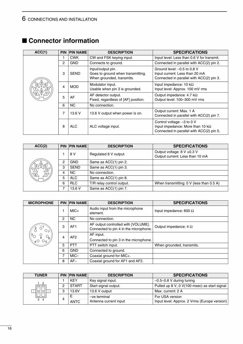
Connector information
ACC(1) PIN PIN NAME DESCRIPTION SPECIFICATIONS1 CWK CW and FSK keying input. Input level: Less than 0.6 V for transmit.2 GND Connects to ground. Connected in parallel with ACC(2) pin 2.
3 SENDInput/output pin.Goes to ground when transmitting.When grounded, transmits.
Ground level: –0.5 to 0.8 VInput current: Less than 20 mAConnected in parallel with ACC(2) pin 3.
4 MODModulator input.Usable when pin 3 is grounded.
Input impedance: 10 kΩInput level: Approx. 100 mV rms
5 AFAF detector output.Fixed, regardless of [AF] position.
Output impedance: 4.7 kΩOutput level: 100–300 mV rms
6 NC No connection.
7 13.6 V 13.6 V output when power is on.Output current: Max. 1 AConnected in parallel with ACC(2) pin 7.
8 ALC ALC voltage input.Control voltage: –3 to 0 VInput impedance: More than 10 kΩConnected in parallel with ACC(2) pin 5.
2
8
4 51 3
6 7
ACC(2) PIN PIN NAME DESCRIPTION SPECIFICATIONS
2 GND Same as ACC(1) pin 2.3 SEND Same as ACC(1) pin 3.
1 8 V Regulated 8 V output.Output voltage: 8 V ±0.3 VOutput current: Less than 10 mA
4 NC No connection.5 ALC Same as ACC(1) pin 8.6 RLC T/R relay control output. When transmitting: 0 V (less than 0.5 A)7 13.6 V Same as ACC(1) pin 7.
24 51 3
6 7
MICROPHONE PIN NAME DESCRIPTION SPECIFICATIONS
2 NC No connection.
1 MIC+Audio input from the microphoneelement.
Input impedance: 600 Ω
4 AF2AF input.
Connected to pin 3 in the microphone.5 PTT PTT switch input. When grounded, transmits.6 GND Connected to ground.
3 AF1AF output controlled with [VOLUME].Connected to pin 4 in the microphone.
Output impedance: 4 Ω
7 MIC– Coaxial ground for MIC+.8 AF– Coaxial ground for AF1 and AF2.
1
7
654
38
2
PIN
TUNER PIN NAME DESCRIPTION SPECIFICATIONS1 KEY Key signal input. –0.5–0.8 V during tuning
4E
ANTC–ve terminalAntenna current input
For USA versionInput level: Approx. 2 Vrms (Europe version)
2 START Start signal output. Pulled up 8 V, 0 V(100 msec) as start signal.3 13.6V 13.6 V output Max. current: 2 A
1 2
3 4
PIN

6CONNECTIONS AND INSTALLATION
17
REMOTE PIN PIN NAME DESCRIPTION SPECIFICATIONS
2 MOD– Coaxial ground for MOD+.
1 MOD+Modulation input from an externalterminal unit.
Input impedance: 600 ΩInput level: Approx. 1.3 mV rms
4 AF– Coaxial ground for AF+.5 NMI+ NMEA data input. NMEA standard format/level6 NMI– Coaxial ground for NMI+.7 NMO+ NMEA data output. NMEA standard format/level
3 AF+AF detector output for an externalterminal unit.
Output impedance: 600 ΩOutput level: 0.25–2.5 V rms
8 NMO– Coaxial ground for NMO+.9 GND Ground for digital equipment.
6 9
51
DC 13.6V PIN NAME DESCRIPTION SPECIFICATIONS
1,4,7 +ve +ve DC input Max. power consumption: 30 A
2, 5,
8–ve –ve DC input
1
4 6
2 3
7 8 9
PIN

CONNECTIONS AND INSTALLATION6
18
Ground connectionThe transceiver and antenna tuner MUST have anadequate ground connection. Otherwise, the overallefficiency of the transceiver and antenna tuner instal-lation will be reduced. Electrolysis, electrical shocksand interference from other equipment could alsooccur.
For best results, use the heaviest gauge wire or strapavailable and make the connection as short as possi-ble. Ground the transceiver and antenna tuner to oneground point, otherwise voltage differences between2 ground points may cause electrolysis.
R CAUTION: The IC-M700PRO has a negativeground. NEVER connect the IC-M700PRO to a“plus-grounding ship,” otherwise the transceiverwill not function.
Ground system example
Good ground points• Ship’s ground terminal• External ground plate• External copper screen
Acceptable ground points• Stainless steel tuna tower• Stainless steel stanchion• Through mast• Through hull• Metal water tank
Undesirable ground points(these points may cause electrolysis)• Engine block• Keel bolt
Unusable ground points(these connections may cause an explosion or elec-trical shock)• Gas or electrical pipe• Fuel tank• Oil-catch pan
Power sourceThe transceiver requires regulated DC power of 13.6V and at least 30 A. There are 3 ways to supplypower:• Direct connection to a 12 V battery in your ship
through the supplied DC power cable.• Use the PS-60 DC POWER SUPPLY to connect to an
AC outlet.• Use the PS-66 DC-DC CONVERTER to connect to a
19–32 V DC power source.
R CAUTION: The supplied DC power cable MUSTbe used to provide power to the transceiver.AVOID exceeding the 3 m (10 ft) length of the DCpower cable. If it is necessary to make a run ofover 3 m, use #6 or similar weight cable instead ofthe supplied DC power cable for a maximum runof 6 m (20 ft).
DC power cable connection
NOTE: Use terminalsfor the cable connection.
Crimp
Solder
or
SuppliedDC power cable
redblack
12 Vbattery
Optional AT-130Transceiver
Copper pipe Metal object Copper screen
yyyyyyyyyyyyyyyyyyyyyyyy

6CONNECTIONS AND INSTALLATION
19
AntennaMost stations operate with a whip or long wire (insu-lated backstay) antenna. However, these antennascannot be connected directly to the transceiver sincetheir impedance may not be matched with the trans-ceiver antenna connector.
With a 50 Ω matched antenna all marine bands can-not be used. The following antenna matcher or an-tenna tuner may be helpful for antenna installation.
D MN-100/MN-100L ANTENNA MATCHERS
D AT-130 AUTOMATIC ANTENNA TUNER
D Non-Icom tunerSome non-Icom tuners may be used with the IC-M700PRO. Please consult your dealer or marina ifyou wish to connect one. The following internal set-tings may be required for connection.
Coaxial cable
To antenna element
Control cable (sold separately)An optional OPC-566 is available
IC-M700PRO
[13.6][E]
[START][KEY]
EKEY13.6
START
AT-130
Antenna wireMN-100/MN-100L
S9(Start port level)
S11(Key port input)
Supplies 8 V when push-ing [TUNE].
Grounded when pushing [TUNE].(used for AT-130—default)
Accepts “HIGH” as an answer back signal.(used for AT-130—default)
Accepts “LOW” as an an-swer back signal.

6 CONNECTIONS AND INSTALLATION
20
MountingR WARNING: NEVER mount the transceiver over-
head. The weight of the transceiver is approximately8 kg., but its apparent weight will increase severalfold due to wave shocks or vibration. The trans-ceiver must be mounted on a flat, hard surface.
D Mounting locationSelect a location that provides easy access to the frontpanel for navigation safety, has good ventilation and isnot subject to sea spray. The face of the transceivershould be at 90 degrees to your line of sight when op-erating it.
RCAUTION: KEEP the transceiver and microphone atleast 1 meter away from your vessel’s magnetic nav-igation compass.
Check the installation angle; the display may not beeasy to read at some angles.
D Mounting example
D Transceiver dimensions
Spring washer
Flatwashers
Nuts(Use two nuts toprevent loosening.)
115
(41 ⁄2
)
67 (
25⁄8)
93.5
(31
1 ⁄16)
100 (315⁄16)
152
(6)
58(2
9 ⁄32)
290 (117⁄16) 280 (11)
312.5 (125⁄16)
350 (1325⁄32)
319 (129⁄16)
143
(55 ⁄8
)
170 (611⁄16)Unit : mm (inchs)

6CONNECTIONS AND INSTALLATION
21
Installing internal optionsD Opening the caseFollow the case and cover opening proceduresshown here when you want to install an option or ad-just a setting for non-Icom tuner control.
➀ Remove the 9 screws from the rear panel, then re-move the rear frame and rear sealing.
➁ Remove the transceiver case.➂ When reassembling the transceiver, check the fol-
lowing points: Internal fan and slits in the case are on the same
side. Front sealing is mated correctly. Rear sealing is attached in the proper orienta-
tion. Screws are tightened securely.
D Installing an optional filter and alarm unitAfter opening the case as shown above, install thedesired option to the position as at right. These op-tions are available (or already built-in) for the followingversions:
After installing the 2-tone alarm unit into a Generalversion, remove the plastic cover on the [ALARM]switch to use the switch.
Version Marine GeneralFL-100CW/FSK NARROW FILTER
optional optional
UT-952-TONE ALARM UNIT
built-in optional
Fuse replacementThe transceiver has 3 fuses to protect internal cir-cuitry, 2 fuses for the fuse holder on the rear paneland 1 for inside. If the transceiver stops functioning,check the fuses below.
Rear frame
Rear sealing
Front sealing
Space for UT-95
Space for the FL-100.(Plug in here. Right orleft orientation is okay.)
5 A
30 A

7 TROUBLESHOOTING
22
PROBLEM POSSIBLE CAUSE SOLUTION REF.
PO
WE
R Power does not come onwhen [POWER] ispushed.
• Power cable is improperly connected.• Blown fuse.
• Reconnect the cable securely.• Check for cause, then replace the fuse
with a spare one.
p. 18p. 21
RE
CE
IVE
No sound comes from thespeaker.
• The [SPEAKER] switch is turned on.• Microphone is not connected.
• The squelch is closed.
• Turn off the [SPEAKER] switch.• Connect the microphone to the
[MICROPHONE] connector.• Push the [SQL] switch to turn the
squelch off.
p. 2p. 2
p. 9
Sensitivity is too low andonly strong signals areaudible.
• Antenna is not properly matched to theoperating frequency.
• Wrong tuner condition is selected in setmode.
• Push [TUNE] to tune the connectedantenna tuner or select “automatictuning” using set mode when anoptional AT-130 is connected.
• Set the proper condition for theconnected tuner.
pgs.2, 11
p. 11
Received audio is unclearor distorted.
• Wrong type of emission is selected.
• AGC is deactivated while receiving astrong signal.
• Noise blanker is turned on whenreceiving a strong signal.
• The [CLARITY] control is rotated toofar clockwise or counterclockwise.
• Push [MODE] to select the properoperating mode.
• Push [AGC] to activate the AGCfunction.
• Push [NB] to turn the noise blanker off.
• Adjust the [CLARITY] control to receiveproper audio output.
p. 3
p. 9
p. 9
p. 9
TR
AN
SM
IT
Your signal does notreach as far away asusual.
• Antenna tuner is improperly matched tothe operating frequency when manualtuning is selected.
• CW or FSK mode is selected for voicetransmission.
• Push [TUNE] to tune the connectedantenna tuner or select “automatictuning” using set mode.
• Push [MODE] to select USB mode (orAM, R3E, etc.).
pgs.2, 11
p. 3
Transmit signal is unclearor distorted.
• Wrong type of emission is selected.
• Microphone is too close to your mouth.
• Push [MODE] to select the properoperating mode.
• Speak into the microphone naturallyand do not hold the microphone tooclose to your mouth.
p. 3
—
DIS
PLA
Y All indicators appear andthe channel numbercannot be read.
• The highest contrast is selected in setmode.
• Set to the proper display contrast. p. 13
What appears to be equipment malfunction may not bedamaging or difficult to solve. Check the following chartbefore making any adjustments or sending the trans-ceiver to an Icom Service Center.

8SPECIFICATIONS AND OPTIONS
23
SpecificationsGENERAL• Frequency coverage:
Receive 500 kHz–29.999 MHzTransmit 1.6– 2.9999 MHz 4.0– 4.9999 MHz
6.0– 6.9999 MHz 8.0– 8.9999 MHz12.0– 13.9999 MHz 16.0–17.9999 MHz18.0– 19.9999 MHz 22.0–22.9999 MHz25.0– 27.5000 MHz
• Mode: USB, AM, CW, FSK and AFSK(available modes differ with version)
• Number of channels: 150 channels (max.)—3 groups of 50
channels each• Antenna impedance: 50 Ω nominal• Usable temp. range: –30°C to +60°C (–22°F to +140°F)• Frequency stability: ±10 Hz (–30°C to +60°C; –22°F to +140°F)
(±20 Hz above 15 MHz for General andMarine versions)
• Power supply requirement: 13.6 V DC±15%(negative and floating groundsavailable depending on version)
• Current drain:Transmit (max. output power) 30 AReceive (max. audio output) 2.5 A (negative ground)
• Dimensions: 291.4(W)×116.4(H)×315(D) mm11.3(W)×4.4(H)×12.8(D) in
• Weight: 7.9 kg; 17.4 lb (negative ground)
TRANSMITTER• Output power: 150 W PEP (60 W above 24 MHz)• Spurious emissions: –75 dB typical
• Carrier suppression: 65 dB typical• Unwanted sideband suppression: 70 dB typical• Microphone impedance: 600 Ω
RECEIVER• Sensitivity
USB, CW, AFSK, FSK, (for 12 dB SINAD):0.35 µV typical (1.8–29.9999 MHz)1.0 µV (1.6–1.7999 MHz)6.3 µV (0.5–1.5999 MHz)
AM (for 10 dB S/N):2.2 µV typical (1.8–29.9999 MHz)6.3 µV (1.6–1.7999 MHz)32 µV (0.5–1.5999 MHz)
• Spurious response rejection: 80 dB typical (1.6–29.9999 MHz)• Audio output power: 5.0 W (at 10% distortion with a 4 Ω load)• Audio impedance: 4 to 8 Ω• Clarity variable range: ±150 Hz
OptionsAT-130 AUTOMATICANTENNA TUNER
MN-100ANTENNA MATCHER
MN-100LANTENNA MATCHER
HS-50 HANDSET
Matches the transceiver to along wire antenna with a mini-mum of insertion loss.
Matches the transceiver to adipole antenna. Covers all HFbands from 1.5 to 30 MHz.8 m × 2 antenna wires comeattached.
Matches the transceiver to along wire antenna. Covers allHF bands from 1.5 to 30 MHz.15 m × 1 antenna wire comesattached.
Provides better audio recep-tion during offshore conditionsand comes in handy for listen-ing privacy on board.
PS-60 DC POWER SUP-PLY
PS-66 DC-DC CON-VERTER
FL-100CW/FSK NARROW FILTER
Provides 13.6 V DC (30 A)output from an AC outlet.
Provides 13.6 V DC (30 A)output from a 19–32 V DCpower source.
Allows better receiver selectiv-ity for CW and FSK.Bandwidth: 500 Hz/–6 dB
UT-95 2-TONE ALARM UNIT
Provides an alarm transmis-sion for emergency use duringmaritime operation.
All stated specifications are subject to change without noticeor obligation.

Count on us!
1-1-32 Kamiminami, Hirano-ku, Osaka 547-0003 Japan
A-5472H-1EXPrinted in JapanCopyright 1997 by Icom Inc.