ic100d evo (rel. 1.0)1592022020 quick reference guide ichill 100devo rel. 1.0 5/40 1 general warning...
TRANSCRIPT
QUICK REFERENCE GUIDE
IC100D EVO
(rel. 1.0)

1592022020 Quick reference guide iCHILL 100DEVO rel. 1.0 3/40
INDEX
1 GENERAL WARNING ................................................................................................ 5
1.1 PLEASE READ BEFORE USING THIS MANUAL ........................................................ 5
1.2 SAFETY PRECAUTIONS ............................................................................................. 5 1.3 PRODUCT DISPOSAL (WEEE)............................................................................................. 6 2 USING THE QUICK REFERENCE GUIDE ................................................................ 6 3 ICHILL 105D / IC107D FEATURES ........................................................................... 7 4 USER INTERFACE .................................................................................................... 8 4.1 MEANING OF THE LEDS ...................................................................................................... 8 4.2 DISPLAY AND ICONS ........................................................................................................... 8 5 DISPLAY LAYOUT ................................................................................................... 10 6 OTHER DISPLAY INFORMATION ........................................................................... 10 6.1 READ THE SET POINT VALUE .......................................................................................... 10 6.2 MODIFY THE SET POINT ................................................................................................... 11 7 KEY FUNCTION ....................................................................................................... 11 7.1 KEY COMBINANTION ......................................................................................................... 12 8 FIRST INSTALLING ................................................................................................. 12 8.1 ON BOARD CLOCK (OPTIONAL) ....................................................................................... 12 8.2 RTC SETUP ........................................................................................................................ 12 9 PARAMETERS PROGRAMMING WITH THE “HOT KEY 64” ............................... 13 9.1 HOW TO PROGRAM THE INSTRUMENT WITH AN ALREADY PROGRAMMED “HOT KEY” (DOWNLOAD) ................................................................................................................................... 13 9.2 HOW TO COPY THE PARAMETER MAP INTO THE “HOT KEY” (UPLOAD)..................... 13 10 PROGRAMMING USING LOCAL USER INTERFACE ............................................ 13 10.1 ENTER PARAMETERS PROGRAMMING LEVEL PR1 ....................................................... 14 10.2 ENTER PARAMETERS PROGRAMMING LEVEL PR2 ....................................................... 14 10.3 ENTER PARAMETERS PROGRAMMING LEVEL PR3 ....................................................... 14 11 MENU ( MENU KEY) ................................................................................................ 15 11.1 ALARM LIST: READ AND RESET ....................................................................................... 15 11.2 ALARM LOG LIST ............................................................................................................... 16 12 REMOTE KEYBOARD VI613 ................................................................................... 16 13 REMOTE LCD PANEL VGI810 OR V2I810 ............................................................. 17 14 REMOTE TOUCH PANEL VTIC10 ........................................................................... 17 15 TABLE OF THE OUTPUT STATUS IN ALARM CONDITION ................................. 18 15.1 MACHINE ALARMS ............................................................................................................ 18 15.2 CIRCUIT ALARM ................................................................................................................. 20 15.3 COMPRESSOR ALARM ...................................................................................................... 21 15.1 WARNING ........................................................................................................................... 21 16 BLACK-OUT............................................................................................................. 21 17 WIRING CONNECTIONS ......................................................................................... 22 17.1 IC105D MODEL: HARDWARE RESOURCES ..................................................................... 22 17.2 IC107D MODEL: HARDWARE RESOURCES ..................................................................... 23 17.1 REMOTE PANEL CONNECTION (VI613 EVO OR V2I810 OR VTIC10) .............................. 25 17.2 ANALOG INPUTS NTC – PTC PROBES ............................................................................. 27 17.3 DIGITAL INPUTS ................................................................................................................. 28
1592022020 Quick reference guide iCHILL 100DEVO rel. 1.0 4/40
17.4 ANALOG INPUT FOR PRESSURE TRANSDUCER PP30 (4 ÷ 20MA SIGNAL) .................. 28 17.5 ANALOG INPUT FOR PRESSURE RATIOMETRIC TRANSDUCER PPR30 (0 ÷ 5V SIGNAL) 29 17.6 PWM OUTPUT FOR CONDENSING FAN SPEED CONTROL ............................................ 30 17.7 PROPORTIONAL OUTPUT FOR FAN CONDENSING CONTROL OR FOR COMPRESSOR INVERTER CONTROLLED OR FOR AUXILIARY OUTPUTS ............................................................ 31 17.8 PROPORTIONAL OUTPUT 0..10V TO CONTROL DUMPER MOTORS ............................. 32 17.9 PROPORTIONAL OUTPUTS CONFIGURED FOR AUX RELAY CONTROL ....................... 34 17.10 CONNECTION TO THE IEV22D OR IEV12D ELECTRONIC EXPANSION VALVE DRIVER 35 18 INSTALLING AND MOUNTING ............................................................................... 36 18.1 MECHANICAL CHARACTERISTIC ..................................................................................... 36 18.2 VERTICAL BOARDS VI613 PANEL CUT-OUT .................................................................... 37 19 ELECTRICAL CONNECTIONS ................................................................................ 38 20 TECHNICAL DATA .................................................................................................. 38 20.1 SUPPLY VOLTAGE ............................................................................................................. 38 20.2 ANALOGUE INPUTS ........................................................................................................... 39 20.3 DIGITAL INPUT ................................................................................................................... 39 20.4 ANALOGUE OUTPUTS ....................................................................................................... 39 20.5 DIGITAL OUTPUTS ............................................................................................................. 40 20.6 PLASTIC CONTAINER ........................................................................................................ 40 20.7 OPERATING AND STORAGE TEMPERATURE ................................................................. 40
1592022020 Quick reference guide iCHILL 100DEVO rel. 1.0 5/40
1 GENERAL WARNING
1.1 PLEASE READ BEFORE USING THIS MANUAL
• This manual is part of the product and should be kept near the instrument for easy and quick reference.
• The instrument shall not be used for purposes different from those described hereunder. It cannot be used as a safety device.
• Check the application limits before proceeding.
• Dixell Srl reserves the right to change the composition of its products, even without notice, ensuring the same and unchanged functionality.
1.2 SAFETY PRECAUTIONS
• Check the supply voltage is correct before connecting the instrument.
• Do not expose to water or moisture: use the controller only within the operating limits avoiding sudden temperature changes with high atmospheric humidity to prevent formation of condensation
• Warning: disconnect all electrical connections before any kind of maintenance.
• The instrument must not be opened.
• In case of failure or faulty operation send the instrument back to the distributor or to “Dixell S.r.l.” with a detailed description of the fault.
• Consider the maximum current which can be applied to each relay (see Technical Data).
• Ensure that the wires for probes, loads and the power supply are separated and far enough from each other, without crossing or intertwining; do not use the same electrical conduit to install high voltage cabling and low voltage cabling.
• The ground connection of the secondary coil of the transformer that powers the device can result in a bad performance; where possible, this connection should be avoided.
• Fit the probe where it is not accessible by the end user.
• In case of applications in industrial environments, the use of mains filters (our mod. FT1) in parallel with inductive loads could be useful.
• The symbol alerts the user of non-insulated “dangerous voltage” within the product area that is sufficiently high to constitute a risk of electric shock to persons.
• The symbol alerts the user of important operating and maintenance (assistance) instructions found in the documentation attached to the device.
Separate the power supply of the device from the rest of the electrical devices connected inside the electrical panel.
1592022020 Quick reference guide iCHILL 100DEVO rel. 1.0 6/40
The connection to ground of the secondary coil of the transformer that supply the device may generate the malfunctionning of the device; where possible this connection must be avoided.
1.3 PRODUCT DISPOSAL (WEEE)
With reference to Directive 2002/96/EC of the European Parliament and of the Council of 27 January 2003 and to the relative national legislation, please note that:
• There lies the obligation not to dispose of electrical and electronic waste as municipal waste but to separate the waste.
• Public or private collection points must be used to dispose of the goods in accordance with local laws. Furthermore, at the end of the product's life, it is also possible to return this to the retailer when a new purchase is made.
• This equipment may contain hazardous substances. Improper use or incorrect disposal can have adverse effects on human health and the environment.
• The symbol shown on the product or the package indicates that the product has been placed on the market after 13 August 2005 and must be disposed of as separated waste.
• Should the product be disposed of incorrectly, sanctions may be applied as stipulated in applicable local regulations regarding waste disposal.
2 USING THE QUICK REFERENCE GUIDE
In this guide, there are some general guidelines regarding the product; more details are in the full manual, to be requested from the Dixell Customer Service department.
1592022020 Quick reference guide iCHILL 100DEVO rel. 1.0 7/40
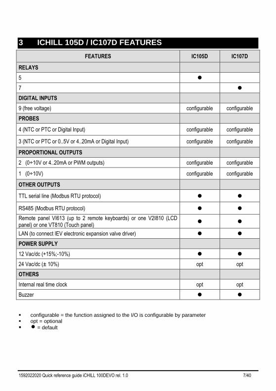
3 ICHILL 105D / IC107D FEATURES
FEATURES IC105D IC107D
RELAYS
5
7
DIGITAL INPUTS
9 (free voltage) configurable configurable
PROBES
4 (NTC or PTC or Digital Input) configurable configurable
3 (NTC or PTC or 0..5V or 4..20mA or Digital Input) configurable configurable
PROPORTIONAL OUTPUTS
2 (0÷10V or 4..20mA or PWM outputs) configurable configurable
1 (0÷10V) configurable configurable
OTHER OUTPUTS
TTL serial line (Modbus RTU protocol)
RS485 (Modbus RTU protocol)
Remote panel VI613 (up to 2 remote keyboards) or one V2I810 (LCD panel) or one VT810 (Touch panel)
LAN (to connect IEV electronic expansion valve driver)
POWER SUPPLY
12 Vac/dc (+15%;-10%)
24 Vac/dc (± 10%) opt opt
OTHERS
Internal real time clock opt opt
Buzzer
configurable = the function assigned to the I/O is configurable by parameter opt = optional
= default
1592022020 Quick reference guide iCHILL 100DEVO rel. 1.0 8/40
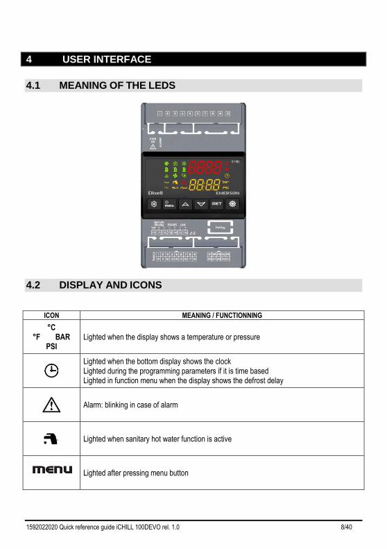
4 USER INTERFACE
4.1 MEANING OF THE LEDS
4.2 DISPLAY AND ICONS
ICON MEANING / FUNCTIONNING
°C °F BAR
PSI Lighted when the display shows a temperature or pressure
Lighted when the bottom display shows the clock Lighted during the programming parameters if it is time based Lighted in function menu when the display shows the defrost delay
Alarm: blinking in case of alarm
Lighted when sanitary hot water function is active
Lighted after pressing menu button
1592022020 Quick reference guide iCHILL 100DEVO rel. 1.0 9/40
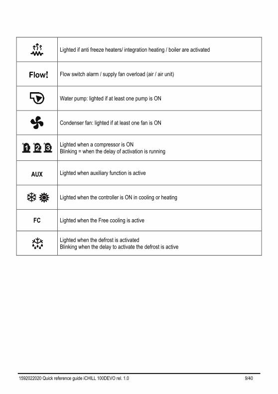
Lighted if anti freeze heaters/ integration heating / boiler are activated
Flow switch alarm / supply fan overload (air / air unit)
Water pump: lighted if at least one pump is ON
Condenser fan: lighted if at least one fan is ON
Lighted when a compressor is ON Blinking = when the delay of activation is running
AUX
Lighted when auxiliary function is active
Lighted when the controller is ON in cooling or heating
FC
Lighted when the Free cooling is active
Lighted when the defrost is activated Blinking when the delay to activate the defrost is active
1592022020 Quick reference guide iCHILL 100DEVO rel. 1.0 10/40
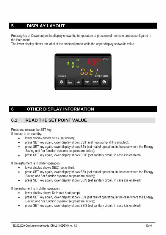
5 DISPLAY LAYOUT
Pressing Up or Down button the display shows the temperature or pressure of the main probes configured in the instrument. The lower display shows the label of the selected probe while the upper display shows its value.
6 OTHER DISPLAY INFORMATION
6.1 READ THE SET POINT VALUE
Press and release the SET key: If the unit is on standby:
• lower display shows SEtC (set chiller);
• press SET key again, lower display shows SEtH (set heat pump, if it is enabled);
• press SET key again, lower display shows SEtr (set real of operation, in the case where the Energy Saving and / or function dynamic set point are active);
• press SET key again, lower display shows SEtS (set sanitary circuit, in case it is enabled) If the instrument is in chiller operation:
• lower display shows SEtC (set chiller);
• press SET key again, lower display shows SEtr (set real of operation, in the case where the Energy Saving and / or function dynamic set point are active);
• press SET key again, lower display shows SEtS (set sanitary circuit, in case it is enabled) If the instrument is in chiller operation:
• lower display shows SetH (set heat pump);
• press SET key again, lower display shows SEtr (set real of operation, in the case where the Energy Saving and / or function dynamic set point are active);
• press SET key again, lower display shows SEtS (set sanitary circuit, in case it is enabled)
1592022020 Quick reference guide iCHILL 100DEVO rel. 1.0 11/40
6.2 MODIFY THE SET POINT
• push SET key for at least 3 seconds
• use the UP or DOWN key to modify the setpoint. In chiller mode it is possible to modify the chiller set point, in heat pump it is possible to modify the heat pump set point, in std-by it is possible to modify both the set point.
• push SET to confirm or wait the timeout (15seconds).
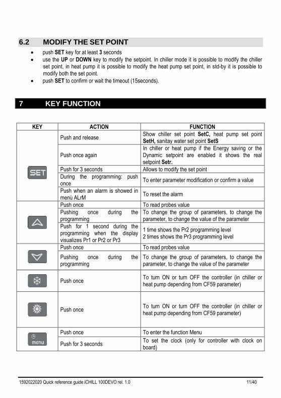
7 KEY FUNCTION
KEY ACTION FUNCTION
Push and release Show chiller set point SetC, heat pump set point SetH, sanitay water set point SetS
Push once again In chiller or heat pump if the Energy saving or the Dynamic setpoint are enabled it shows the real setpoint Setr.
Push for 3 seconds Allows to modify the set point
During the programming: push once
To enter parameter modification or confirm a value
Push when an alarm is showed in menù ALrM
To reset the alarm
Push once To read probes value
Pushing once during the programming
To change the group of parameters, to change the parameter, to change the value of the parameter
Push for 1 second during the programming when the display visualizes Pr1 or Pr2 or Pr3
1 time shows the Pr2 programming level 2 times shows the Pr3 programming level
Push once To read probes value
Pushing once during the programming
To change the group of parameters, to change the parameter, to change the value of the parameter
Push once
To turn ON or turn OFF the controller (in chiller or heat pump depending from CF59 parameter)
Push once
To turn ON or turn OFF the controller (in chiller or heat pump depending from CF59 parameter)
Push once To enter the function Menu
Push for 3 seconds To set the clock (only for controller with clock on board)
1592022020 Quick reference guide iCHILL 100DEVO rel. 1.0 12/40
Pushing once during the programming
To exit from a group of parameters
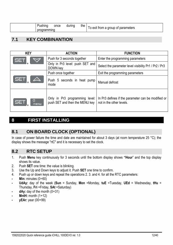
7.1 KEY COMBINANTION
KEY ACTION FUNCTION
+
Push for 3 seconds together Enter the programming parameters
Only in Pr3 level: push SET and DOWN key
Select the parameter level visibility Pr1 / Pr2 / Pr3
+
Push once together Exit the programming parameters
Push 5 seconds in heat pump mode
Manual defrost
+
Only in Pr3 programming level: push SET and then the MENU key
In Pr3 defines if the parameter can be modified or not in the other levels.
8 FIRST INSTALLING
8.1 ON BOARD CLOCK (OPTIONAL)
In case of power failure the time and date are maintained for about 3 days (at room temperature 25 °C); the display shows the message "rtC" and it is necessary to set the clock.
8.2 RTC SETUP
1. Push Menu key continuously for 3 seconds until the bottom display shows “Hour” and the top display shows its value.
2. Push SET one time: the value is blinking. 3. Use the Up and Down keys to adjust it. Push SET one time to confirm. 4. Push up or down keys and repeat the operations 2. 3. and 4. for all the RTC parameters: - Min: minutes (0÷60) - UdAy: day of the week (Sun = Sunday, Mon =Monday, tuE =Tuesday, UEd = Wednesday, tHu =
Thursday, Fri =Friday, SAt =Saturday) - dAy: day of the month (0÷31) - MntH: month (1÷12) - yEAr: year (00÷99)
1592022020 Quick reference guide iCHILL 100DEVO rel. 1.0 13/40
9 PARAMETERS PROGRAMMING WITH THE “HOT KEY 64”
9.1 HOW TO PROGRAM THE INSTRUMENT WITH AN ALREADY
PROGRAMMED “HOT KEY” (DOWNLOAD)
1. Power off the instrument 2. Insert the hot key already programmed (by software Wizmate or other instrument) 3. Power on the instrument 4. Automatically the parameters are downloaded During the download the regulation is locked and the top display shows the “doL” blinking label. At the end of the download will appear:
• “End” if the programming procedure is completely OK, after 30seconds the regulation starts automatically.
• “Err” if the programming procedure has found an error and the parameter have not been transferred. In this case turn off and then on the instrument supply to repeat the operation or remove the hot key, with power supply off, to restart the regulation.
9.2 HOW TO COPY THE PARAMETER MAP INTO THE “HOT KEY”
(UPLOAD)
1. Power on the instrument 2. Insert the hot key 3. Enter the function Menu 4. Select the UPL function (on the bottom display) 5. Push SET key and immediately the instrument starts transfer the parameters into the Hot key. During the upload the regulation is locked and the top display shows the “UPL” blinking label. At the end of the UPLOAD will appear:
1. “End” if the programming procedure is completely OK, after 30seconds the regulation starts automatically.
2. “Err” if the programming procedure has found an error and the parameter have not been transferred. Repeat the procedure.
To exit the UPL function push the MENU key or wait the time-out (15 sec).
10 PROGRAMMING USING LOCAL USER INTERFACE
Though the keyboard it is possible to modify the values of the parameters and set for each one of them the visibility and editability; each parameter can be made visible at different levels of users: 1. Pr1 User level (default Password = 1)
2. Pr2 Maintenance level (default Password = 2) 3. Pr3 OEM level (default Password = 3)
The default password for resetting the alarm history and compressor overload alarm is 4. Passwords can be customized using specific parameters; in the case in which it is necessary to access the parameters and the passwords have been changed, it is necessary to contact the machine manufacturer to obtain the necessary information.
1592022020 Quick reference guide iCHILL 100DEVO rel. 1.0 14/40
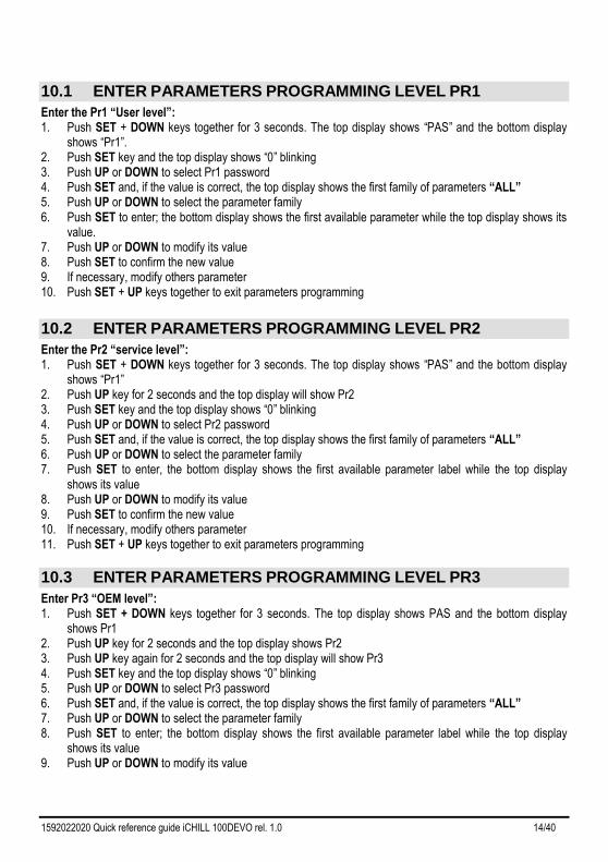
10.1 ENTER PARAMETERS PROGRAMMING LEVEL PR1
Enter the Pr1 “User level”: 1. Push SET + DOWN keys together for 3 seconds. The top display shows “PAS” and the bottom display
shows “Pr1”. 2. Push SET key and the top display shows “0” blinking 3. Push UP or DOWN to select Pr1 password 4. Push SET and, if the value is correct, the top display shows the first family of parameters “ALL” 5. Push UP or DOWN to select the parameter family 6. Push SET to enter; the bottom display shows the first available parameter while the top display shows its
value. 7. Push UP or DOWN to modify its value 8. Push SET to confirm the new value 9. If necessary, modify others parameter 10. Push SET + UP keys together to exit parameters programming
10.2 ENTER PARAMETERS PROGRAMMING LEVEL PR2
Enter the Pr2 “service level”: 1. Push SET + DOWN keys together for 3 seconds. The top display shows “PAS” and the bottom display
shows “Pr1” 2. Push UP key for 2 seconds and the top display will show Pr2 3. Push SET key and the top display shows “0” blinking 4. Push UP or DOWN to select Pr2 password 5. Push SET and, if the value is correct, the top display shows the first family of parameters “ALL” 6. Push UP or DOWN to select the parameter family 7. Push SET to enter, the bottom display shows the first available parameter label while the top display
shows its value 8. Push UP or DOWN to modify its value 9. Push SET to confirm the new value 10. If necessary, modify others parameter 11. Push SET + UP keys together to exit parameters programming
10.3 ENTER PARAMETERS PROGRAMMING LEVEL PR3
Enter Pr3 “OEM level”: 1. Push SET + DOWN keys together for 3 seconds. The top display shows PAS and the bottom display
shows Pr1 2. Push UP key for 2 seconds and the top display shows Pr2 3. Push UP key again for 2 seconds and the top display will show Pr3 4. Push SET key and the top display shows “0” blinking 5. Push UP or DOWN to select Pr3 password 6. Push SET and, if the value is correct, the top display shows the first family of parameters “ALL” 7. Push UP or DOWN to select the parameter family 8. Push SET to enter; the bottom display shows the first available parameter label while the top display
shows its value 9. Push UP or DOWN to modify its value
1592022020 Quick reference guide iCHILL 100DEVO rel. 1.0 15/40
10. Push SET to confirm the new value 11. If necessary, modify others parameter 12. Push SET + UP keys together to exit parameters programming
11 MENU ( MENU KEY)
Enter the menu: • press the menu button; • press the UP or DOWN button to select the submenu; • press the SET to enter the submenu.
Exit menu functions: • Press the menu button or wait the time-out. Entering the menu, it is possbile to:
• ALrM Read and reset the alarms
• ALOG Read and reset the alarm log
• UPL Upload the parameter into the Hot Key
• CrEn Enable – disable one or the two circuits
• COEn Enable – disable one of the compressors
• Hour Read and reset the number of compressor running hour
• COSn Read and reset the number of compressor starts-up
• COdt Read the compressor discharge temperature
• Cond Read the condensing fan speed percentage of the proportional output
• Pout Read the percentage of the proportional output 0 ÷ 10 Vdc
• PoEn Enable – disable evaporator or condenser water pumps
• dF Time counting to next defrost cycle, under heat pump mode,
• uS Read the probe temperatures that enabled to control the auxiliary output
• SoL Read temperature, Set point and output status of solar panel
• FC Read temperature, Set point and output status of Free cooling
• trEM Read probe temperature of the remote panels
• Et1 Read temperature, pressure, set point of the electronic expansion valve 1
• Et2 Read temperature, pressure, set point of the electronic expansion valve 2
• REC Enable / disable recovery function
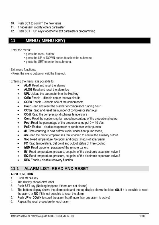
11.1 ALARM LIST: READ AND RESET
ALrM FUNCTION 1. Push MENU key 2. The display shows AlrM label 3. Push SET key (Nothing happens if there are not alarms) 4. The bottom display shows the alarm code and the top display shows the label rSt, if it is possible to reset
the alarm, or NO if it is not possible to reset the alarm 5. Push UP or DOWN to scroll the alarm list (if more than one alarm is active) 6. Repeat the reset procedure for each alarm
1592022020 Quick reference guide iCHILL 100DEVO rel. 1.0 16/40
7. To exit the ALrM reset, push MENU or wait the timeout.
11.2 ALARM LOG LIST
ALOG FUNCTION 1. Push MENU key 2. Push UP or DOWN to select ALOG 3. Push SET key 4. The bottom display shows the alarm label, the top display shows a number in the range 00 to 99. 5. Use the UP or DOWN keys to scroll the list. 6. To exit the ALOG function push MENU or wait the timeout. Erase the Alarm log list 1. Push MENU key 2. Push UP or DOWN to select ALOG 3. Push the SET key 4. Push UP or DOWN keys and search the ArSt label on the bottom display; the top display shows PAS. 5. Push SET; the bottom display shows PAS and the top display shows “0” blinking 6. Push UP or DOWN to set the password 7. If the password is OK the label ArST blinks for 5 seconds then the display returns to normal condition
read-out 8. If the password is not correct the display shows PAS again 9. To exit, push the MENU key or wait the timeout. The standard password to reset the alarm log is “4”.
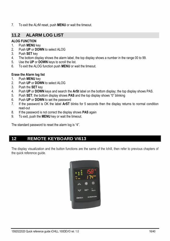
12 REMOTE KEYBOARD VI613
The display visualization and the button functions are the same of the Ichill, then refer to previous chapters of the quick reference guide.
1592022020 Quick reference guide iCHILL 100DEVO rel. 1.0 17/40
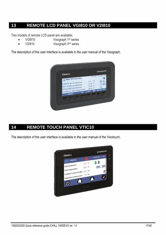
13 REMOTE LCD PANEL VGI810 OR V2I810
Two models of remote LCD panel are available;
• VGI810 Visograph 1st series
• V2I810 Visograph IInd seres The description of the user interface is available in the user manual of the Visograph.
14 REMOTE TOUCH PANEL VTIC10
The description of the user interface is available in the user manual of the Visotouch.
1592022020 Quick reference guide iCHILL 100DEVO rel. 1.0 18/40
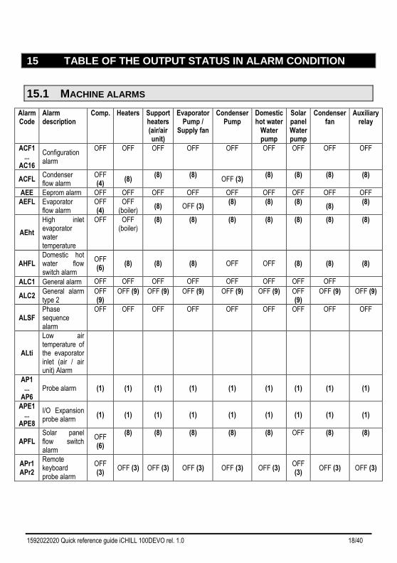
15 TABLE OF THE OUTPUT STATUS IN ALARM CONDITION
15.1 MACHINE ALARMS
Alarm Code
Alarm description
Comp.
Heaters
Support heaters (air/air unit)
Evaporator Pump /
Supply fan
Condenser Pump
Domestic hot water
Water pump
Solar panel Water pump
Condenser fan
Auxiliary relay
ACF1 ...
AC16
Configuration alarm
OFF OFF OFF OFF OFF OFF OFF OFF OFF
ACFL Condenser flow alarm
OFF (4)
(8) (8) (8)
OFF (3) (8) (8) (8) (8)
AEE Eeprom alarm OFF OFF OFF OFF OFF OFF OFF OFF OFF
AEFL Evaporator flow alarm
OFF (4)
OFF (boiler)
(8) OFF (3) (8) (8) (8)
(8) (8)
AEht
High inlet evaporator water temperature
OFF OFF (boiler)
(8) (8) (8) (8) (8) (8) (8)
AHFL Domestic hot water flow switch alarm
OFF (6)
(8) (8) (8) OFF OFF (8) (8) (8)
ALC1 General alarm OFF OFF OFF OFF OFF OFF OFF OFF
ALC2 General alarm type 2
OFF (9)
OFF (9) OFF (9) OFF (9) OFF (9) OFF (9) OFF (9)
OFF (9) OFF (9)
ALSF Phase sequence alarm
OFF OFF OFF OFF OFF OFF OFF OFF OFF
ALti
Low air temperature of the evaporator inlet (air / air unit) Alarm
AP1 ...
AP6 Probe alarm (1) (1) (1) (1) (1) (1) (1) (1) (1)
APE1 ...
APE8
I/O Expansion probe alarm
(1) (1) (1) (1) (1) (1) (1) (1) (1)
APFL Solar panel flow switch alarm
OFF (6)
(8) (8) (8) (8) (8) OFF (8) (8)
APr1 APr2
Remote keyboard probe alarm
OFF (3)
OFF (3) OFF (3) OFF (3) OFF (3) OFF (3) OFF (3)
OFF (3) OFF (3)
1592022020 Quick reference guide iCHILL 100DEVO rel. 1.0 19/40
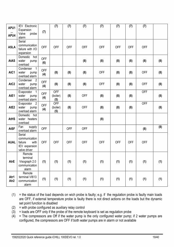
APU1 ...
APU4
IEV Electronic Expansion Valve probe alarm
(7)
(7) (7) (7) (7) (7) (7) (7)
ASLA
Serial communication failure with I/O expansion
OFF OFF OFF OFF OFF OFF OFF OFF
AtAS Domestic hot water pump overload
OFF (6)
(8) (8) (8) (8) (8) (8)
AtC1 Condenser 1 water pump overload alarm
OFF (4)
(8) (8) (8) OFF (8) (8) OFF (8)
AtC2 Condenser 2 water pump overload alarm
OFF (4)
(8) (8) (8) OFF (8) (8) OFF (8)
AtE1 Evaporator 1 water pump overload alarm
OFF (4)
OFF (boiler)
(5) (8) OFF (8) (8) (8)
OFF (8)
AtE2 Evaporator 2 water pump overload alarm
OFF (4)
OFF (boiler)
(5) (8) OFF (8) (8) (8)
OFF (8)
AtHS Domestic hot water heaters overload
(8)
AtSF Fan supply overload alarm
OFF OFF OFF
(8) (8)
AUAL
Serial communication failure with IEV expansion valve driver
OFF OFF OFF OFF OFF OFF OFF OFF
AtrE
Remote terminal
Visograph 2.0 communication
alarm
(1) (1) (1) (1) (1) (1) (1) (1) (1)
Atr1 Atr2
Remote terminal VI613 communication
alarm
(1) (1) (1) (1) (1) (1) (1) (1) (1)
(1) = the status of the load depends on wich probe is faulty; e.g. if the regulation probe is faulty main loads are OFF, if external temperature probe is faulty there is not direct actions on the loads but the dynamic set point function is disabled
(2) = with probe configured as auxiliary relay control (3) = loads are OFF only if the probe of the remote keyboard is set as regulation probe (4) = The compressors are Off if the water pump is the only configured water pump; if 2 water pumps are
configured, the compressors are OFF if both water pumps are in alarm or not available
1592022020 Quick reference guide iCHILL 100DEVO rel. 1.0 20/40
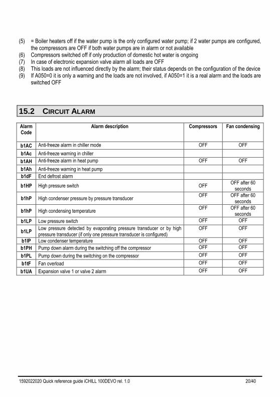
(5) = Boiler heaters off if the water pump is the only configured water pump; if 2 water pumps are configured, the compressors are OFF if both water pumps are in alarm or not available
(6) Compressors switched off if only production of domestic hot water is ongoing (7) In case of electronic expansion valve alarm all loads are OFF (8) This loads are not influenced directly by the alarm; their status depends on the configuration of the device (9) If A050=0 it is only a warning and the loads are not involved, if A050=1 it is a real alarm and the loads are
switched OFF
15.2 CIRCUIT ALARM
Alarm Code
Alarm description Compressors Fan condensing
b1AC Anti-freeze alarm in chiller mode OFF OFF
b1Ac Anti-freeze warning in chiller
b1AH Anti-freeze alarm in heat pump OFF OFF
b1Ah Anti-freeze warning in heat pump
b1dF End defrost alarm
b1HP High pressure switch OFF OFF after 60
seconds
b1hP High condenser pressure by pressure transducer OFF OFF after 60
seconds
b1hP High condensing temperature OFF OFF after 60
seconds
b1LP Low pressure switch OFF OFF
b1LP Low pressure detected by evaporating pressure transducer or by high pressure transducer (if only one pressure transducer is configured)
OFF OFF
b1lP Low condenser temperature OFF OFF
b1PH Pump down alarm during the switching off the compressor OFF OFF
b1PL Pump down during the switching on the compressor OFF OFF
b1tF Fan overload OFF OFF
b1UA Expansion valve 1 or valve 2 alarm OFF OFF
1592022020 Quick reference guide iCHILL 100DEVO rel. 1.0 21/40
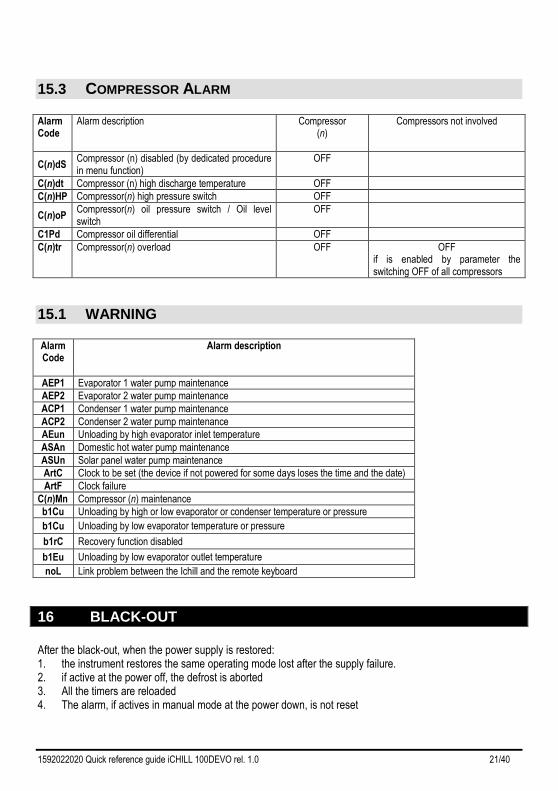
15.3 COMPRESSOR ALARM
Alarm Code
Alarm description Compressor (n)
Compressors not involved
C(n)dS Compressor (n) disabled (by dedicated procedure in menu function)
OFF
C(n)dt Compressor (n) high discharge temperature OFF
C(n)HP Compressor(n) high pressure switch OFF
C(n)oP Compressor(n) oil pressure switch / Oil level switch
OFF
C1Pd Compressor oil differential OFF
C(n)tr Compressor(n) overload OFF OFF if is enabled by parameter the switching OFF of all compressors
15.1 WARNING
Alarm Code
Alarm description
AEP1 Evaporator 1 water pump maintenance
AEP2 Evaporator 2 water pump maintenance
ACP1 Condenser 1 water pump maintenance
ACP2 Condenser 2 water pump maintenance
AEun Unloading by high evaporator inlet temperature
ASAn Domestic hot water pump maintenance
ASUn Solar panel water pump maintenance
ArtC Clock to be set (the device if not powered for some days loses the time and the date)
ArtF Clock failure
C(n)Mn Compressor (n) maintenance
b1Cu Unloading by high or low evaporator or condenser temperature or pressure
b1Cu Unloading by low evaporator temperature or pressure
b1rC Recovery function disabled
b1Eu Unloading by low evaporator outlet temperature
noL Link problem between the Ichill and the remote keyboard
16 BLACK-OUT
After the black-out, when the power supply is restored: 1. the instrument restores the same operating mode lost after the supply failure. 2. if active at the power off, the defrost is aborted 3. All the timers are reloaded 4. The alarm, if actives in manual mode at the power down, is not reset
1592022020 Quick reference guide iCHILL 100DEVO rel. 1.0 22/40
17 WIRING CONNECTIONS
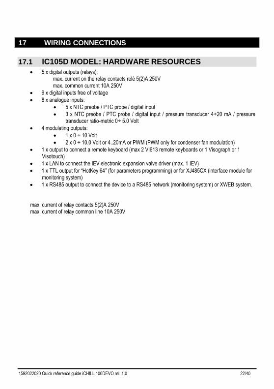
17.1 IC105D MODEL: HARDWARE RESOURCES
• 5 x digital outputs (relays): max. current on the relay contacts relè 5(2)A 250V max. common current 10A 250V
• 9 x digital inputs free of voltage
• 8 x analogue inputs:
• 5 x NTC preobe / PTC probe / digital input
• 3 x NTC preobe / PTC probe / digital input / pressure transducer 4÷20 mA / pressure transducer ratio-metric 0÷ 5.0 Volt
• 4 modulating outputs:
• 1 x 0 ÷ 10 Volt
• 2 x 0 ÷ 10.0 Volt or 4..20mA or PWM (PWM only for condenser fan modulation)
• 1 x output to connect a remote keyboard (max 2 VI613 remote keyboards or 1 Visograph or 1 Visotouch)
• 1 x LAN to connect the IEV electronic expansion valve driver (max. 1 IEV)
• 1 x TTL output for “HotKey 64” (for parameters programming) or for XJ485CX (interface module for monitoring system)
• 1 x RS485 output to connect the device to a RS485 network (monitoring system) or XWEB system. max. current of relay contacts 5(2)A 250V max. current of relay common line 10A 250V
1592022020 Quick reference guide iCHILL 100DEVO rel. 1.0 23/40
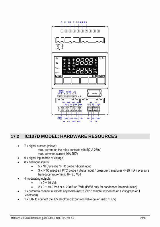
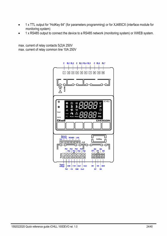
17.2 IC107D MODEL: HARDWARE RESOURCES
• 7 x digital outputs (relays): max. current on the relay contacts relè 5(2)A 250V max. common current 10A 250V
• 9 x digital inputs free of voltage
• 8 x analogue inputs:
• 5 x NTC preobe / PTC probe / digital input
• 3 x NTC preobe / PTC probe / digital input / pressure transducer 4÷20 mA / pressure transducer ratio-metric 0÷ 5.0 Volt
• 4 modulating outputs:
• 1 x 0 ÷ 10 Volt
• 2 x 0 ÷ 10.0 Volt or 4..20mA or PWM (PWM only for condenser fan modulation)
• 1 x output to connect a remote keyboard (max 2 VI613 remote keyboards or 1 Visograph or 1 Visotouch)
• 1 x LAN to connect the IEV electronic expansion valve driver (max. 1 IEV)
1592022020 Quick reference guide iCHILL 100DEVO rel. 1.0 24/40
• 1 x TTL output for “HotKey 64” (for parameters programming) or for XJ485CX (interface module for monitoring system)
• 1 x RS485 output to connect the device to a RS485 network (monitoring system) or XWEB system. max. current of relay contacts 5(2)A 250V max. current of relay common line 10A 250V
1592022020 Quick reference guide iCHILL 100DEVO rel. 1.0 25/40
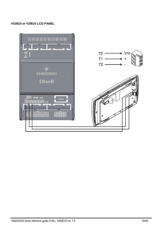
17.1 REMOTE PANEL CONNECTION (VI613 EVO OR V2I810 OR
VTIC10)
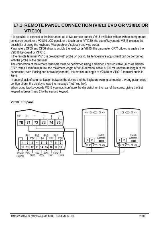
It is possible to connect to the instrument up to two remote panels VI613 available with or without temperature sensor on board, or a V2I810 LCD panel, or a touch panel VTIC10; the use of keyboards VI613 exclude the possibility of using the keyboard Visograph or Visotouch and vice versa. Parameters CF55 and CF56 allow to enable the keyboards VI613; the parameter CF74 allows to enable the V2I810 keyboard or VTIC10. If the remote terminal VI613 is provided with probe on board, the temperature adjustment can be performed with the probe of the terminal. The connection of the remote terminals must be performed using a shielded / twisted cable (such as Belden 8772, wires 1 mm2 minimum); the maximum length of VI613 terminal cable is 100 mt. (maximum length of the connection, both if using one or two keyboards), the maximum length of V2I810 or VTIC10 terminal cable is 60mt. In case of lack of communication between the device and the keyboard (wrong connection, wrong parameters configuration), the display shows the message "noL" (no link). When using two keyboards VI613 you must configure the dip switch on the rear of the same, giving the first keypad address 1 and 2 to the second keypad.
VI613 LED panel
1592022020 Quick reference guide iCHILL 100DEVO rel. 1.0 26/40
VGI810 or V2I810 LCD PANEL
1592022020 Quick reference guide iCHILL 100DEVO rel. 1.0 27/40
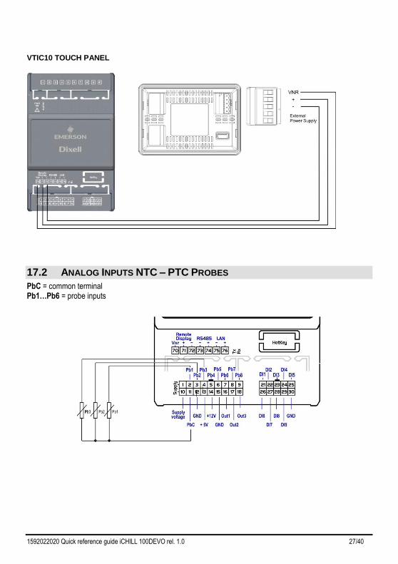
VTIC10 TOUCH PANEL
17.2 ANALOG INPUTS NTC – PTC PROBES
PbC = common terminal Pb1…Pb6 = probe inputs
1592022020 Quick reference guide iCHILL 100DEVO rel. 1.0 28/40
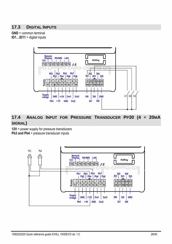
17.3 DIGITAL INPUTS
GND = common terminal ID1…ID11 = digital inputs
17.4 ANALOG INPUT FOR PRESSURE TRANSDUCER PP30 (4 ÷ 20MA
SIGNAL)
12V = power supply for pressure transducers Pb3 and Pb4 = pressure transducer inputs
1592022020 Quick reference guide iCHILL 100DEVO rel. 1.0 29/40
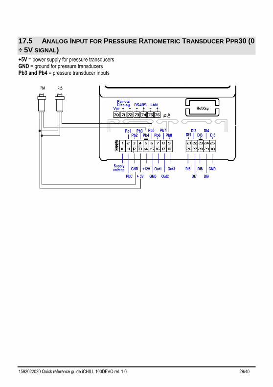
17.5 ANALOG INPUT FOR PRESSURE RATIOMETRIC TRANSDUCER PPR30 (0
÷ 5V SIGNAL)
+5V = power supply for pressure transducers GND = ground for pressure transducers Pb3 and Pb4 = pressure transducer inputs
1592022020 Quick reference guide iCHILL 100DEVO rel. 1.0 30/40
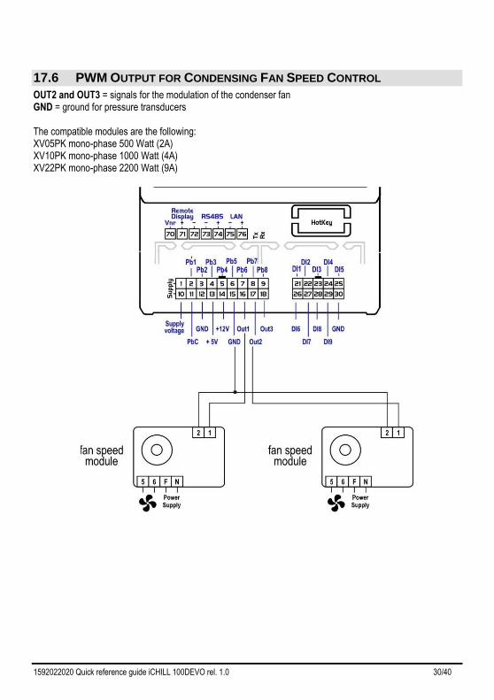
17.6 PWM OUTPUT FOR CONDENSING FAN SPEED CONTROL
OUT2 and OUT3 = signals for the modulation of the condenser fan GND = ground for pressure transducers The compatible modules are the following: XV05PK mono-phase 500 Watt (2A) XV10PK mono-phase 1000 Watt (4A) XV22PK mono-phase 2200 Watt (9A)
1592022020 Quick reference guide iCHILL 100DEVO rel. 1.0 31/40
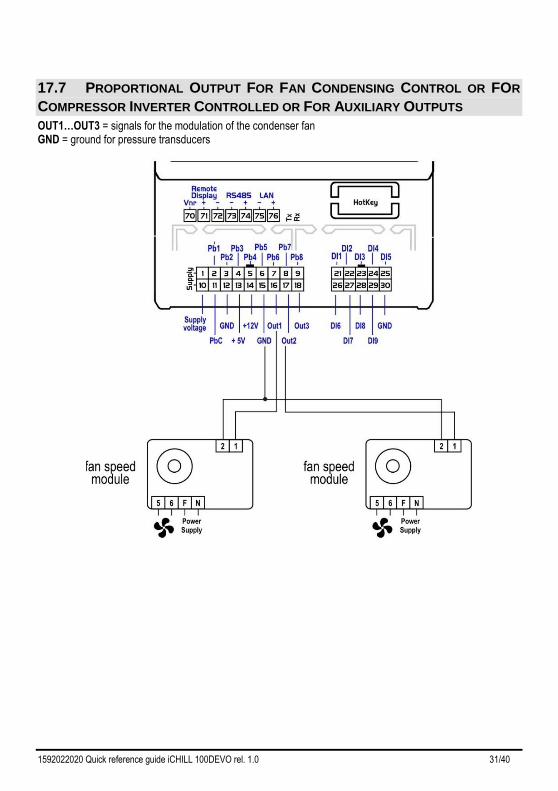
17.7 PROPORTIONAL OUTPUT FOR FAN CONDENSING CONTROL OR FOR
COMPRESSOR INVERTER CONTROLLED OR FOR AUXILIARY OUTPUTS
OUT1…OUT3 = signals for the modulation of the condenser fan GND = ground for pressure transducers
1592022020 Quick reference guide iCHILL 100DEVO rel. 1.0 32/40
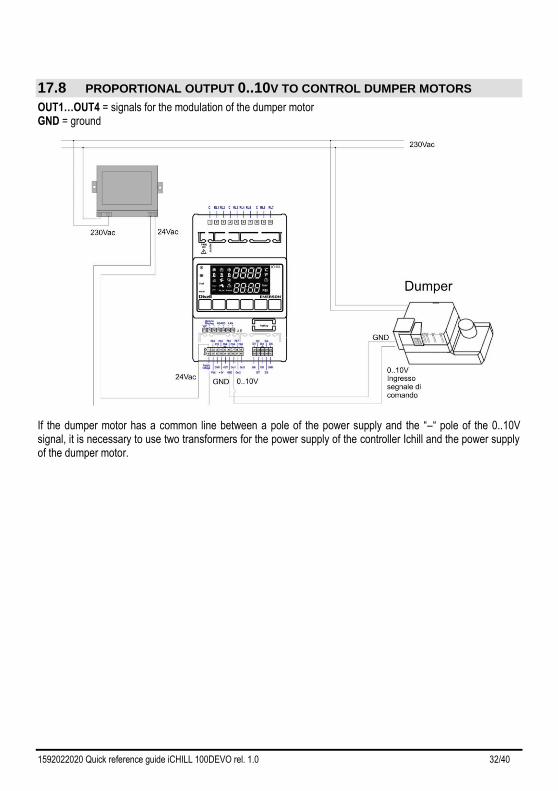
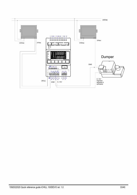
17.8 PROPORTIONAL OUTPUT 0..10V TO CONTROL DUMPER MOTORS
OUT1…OUT4 = signals for the modulation of the dumper motor GND = ground
If the dumper motor has a common line between a pole of the power supply and the “–“ pole of the 0..10V signal, it is necessary to use two transformers for the power supply of the controller Ichill and the power supply of the dumper motor.
1592022020 Quick reference guide iCHILL 100DEVO rel. 1.0 33/40
1592022020 Quick reference guide iCHILL 100DEVO rel. 1.0 34/40
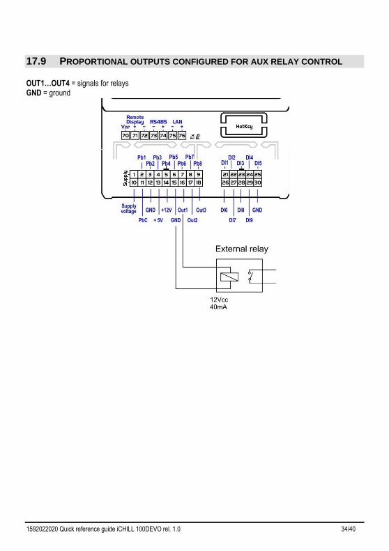
17.9 PROPORTIONAL OUTPUTS CONFIGURED FOR AUX RELAY CONTROL
OUT1…OUT4 = signals for relays GND = ground
1592022020 Quick reference guide iCHILL 100DEVO rel. 1.0 35/40
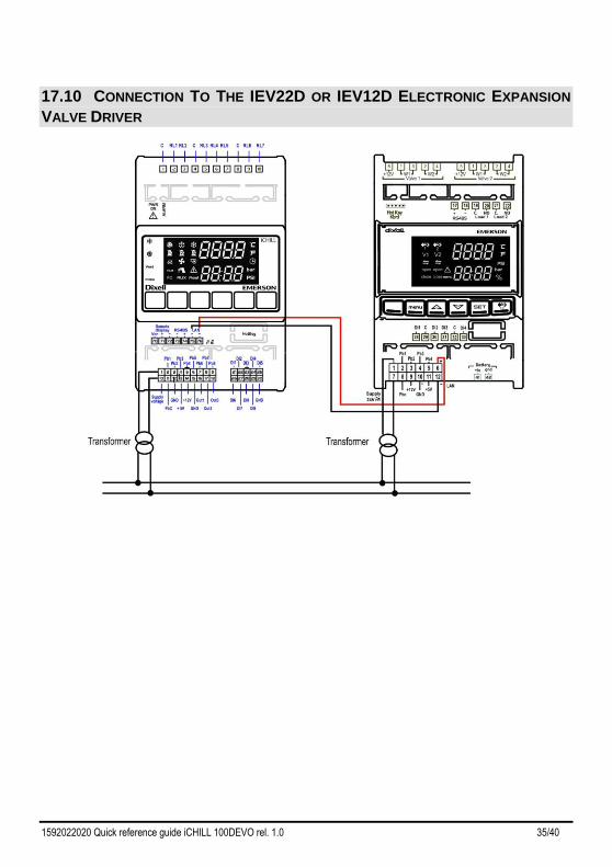
17.10 CONNECTION TO THE IEV22D OR IEV12D ELECTRONIC EXPANSION
VALVE DRIVER
1592022020 Quick reference guide iCHILL 100DEVO rel. 1.0 36/40
18 INSTALLING AND MOUNTING
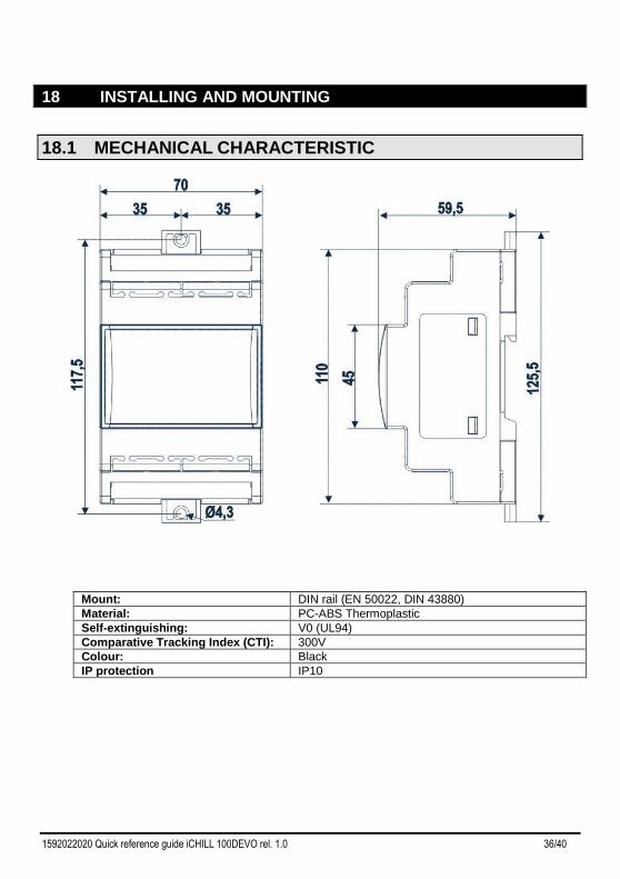
18.1 MECHANICAL CHARACTERISTIC
Mount: DIN rail (EN 50022, DIN 43880)
Material: PC-ABS Thermoplastic
Self-extinguishing: V0 (UL94)
Comparative Tracking Index (CTI): 300V
Colour: Black
IP protection IP10
1592022020 Quick reference guide iCHILL 100DEVO rel. 1.0 37/40
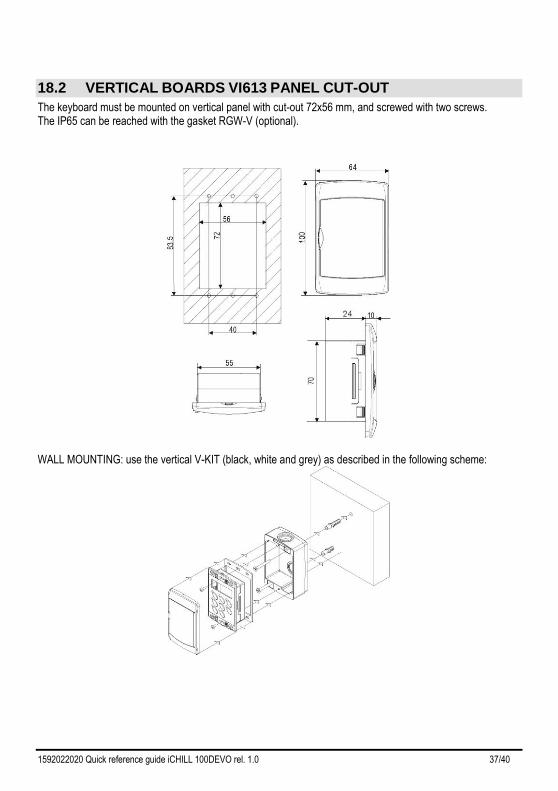
18.2 VERTICAL BOARDS VI613 PANEL CUT-OUT
The keyboard must be mounted on vertical panel with cut-out 72x56 mm, and screwed with two screws. The IP65 can be reached with the gasket RGW-V (optional).
WALL MOUNTING: use the vertical V-KIT (black, white and grey) as described in the following scheme:
1592022020 Quick reference guide iCHILL 100DEVO rel. 1.0 38/40
19 ELECTRICAL CONNECTIONS
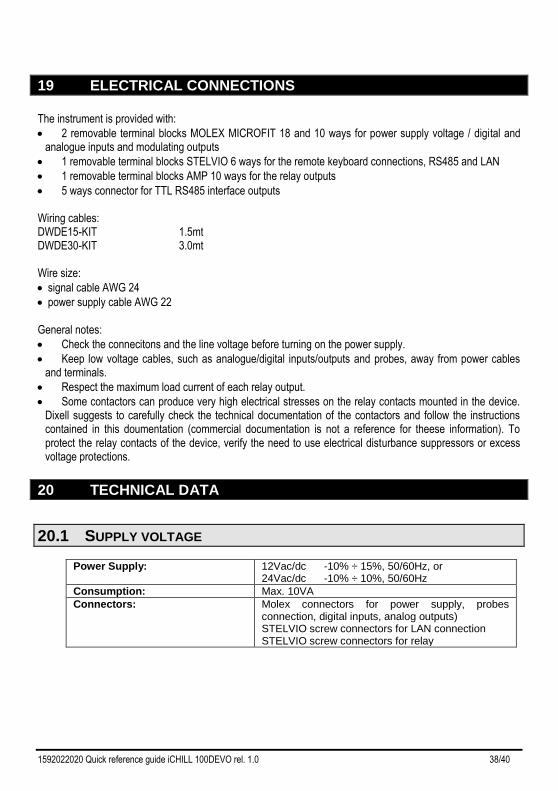
The instrument is provided with:
• 2 removable terminal blocks MOLEX MICROFIT 18 and 10 ways for power supply voltage / digital and analogue inputs and modulating outputs
• 1 removable terminal blocks STELVIO 6 ways for the remote keyboard connections, RS485 and LAN
• 1 removable terminal blocks AMP 10 ways for the relay outputs
• 5 ways connector for TTL RS485 interface outputs Wiring cables: DWDE15-KIT 1.5mt DWDE30-KIT 3.0mt Wire size:
• signal cable AWG 24
• power supply cable AWG 22 General notes:
• Check the connecitons and the line voltage before turning on the power supply.
• Keep low voltage cables, such as analogue/digital inputs/outputs and probes, away from power cables and terminals.
• Respect the maximum load current of each relay output.
• Some contactors can produce very high electrical stresses on the relay contacts mounted in the device. Dixell suggests to carefully check the technical documentation of the contactors and follow the instructions contained in this doumentation (commercial documentation is not a reference for theese information). To protect the relay contacts of the device, verify the need to use electrical disturbance suppressors or excess voltage protections.
20 TECHNICAL DATA
20.1 SUPPLY VOLTAGE
Power Supply: 12Vac/dc -10% ÷ 15%, 50/60Hz, or 24Vac/dc -10% ÷ 10%, 50/60Hz
Consumption: Max. 10VA
Connectors: Molex connectors for power supply, probes connection, digital inputs, analog outputs) STELVIO screw connectors for LAN connection STELVIO screw connectors for relay
1592022020 Quick reference guide iCHILL 100DEVO rel. 1.0 39/40
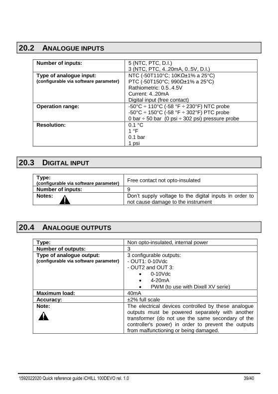
20.2 ANALOGUE INPUTS
Number of inputs: 5 (NTC, PTC, D.I.) 3 (NTC, PTC, 4..20mA, 0..5V, D.I.)
Type of analogue input: (configurable via software parameter)
NTC (-50T110°C; 10KΩ±1% a 25°C) PTC (-50T150°C; 990Ω±1% a 25°C) Rathiometric: 0.5..4.5V Current: 4..20mA Digital input (free contact)
Operation range: -50°C ÷ 110°C (-58 °F ÷ 230°F) NTC probe -50°C ÷ 150°C (-58 °F ÷ 302°F) PTC probe 0 bar ÷ 50 bar (0 psi ÷ 302 psi) pressure probe
Resolution: 0.1 °C 1 °F 0.1 bar 1 psi
20.3 DIGITAL INPUT
Type: (configurable via software parameter)
Free contact not opto-insulated
Number of inputs: 9
Notes: Don’t supply voltage to the digital inputs in order to not cause damage to the instrument
20.4 ANALOGUE OUTPUTS
Type: Non opto-insulated, internal power
Number of outputs: 3
Type of analogue output: (configurable via software parameter)
3 configurable outputs: - OUT1: 0-10Vdc - OUT2 and OUT 3:
• 0-10Vdc
• 4-20mA
• PWM (to use with Dixell XV serie)
Maximum load: 40mA
Accuracy: ±2% full scale
Note: The electrical devices controlled by these analogue outputs must be powered separately with another transformer (do not use the same secondary of the controller's power) in order to prevent the outputs from malfunctioning or being damaged.
1592022020 Quick reference guide iCHILL 100DEVO rel. 1.0 40/40
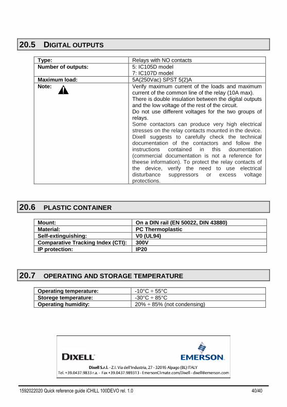
20.5 DIGITAL OUTPUTS
Type: Relays with NO contacts
Number of outputs: 5: IC105D model 7: IC107D model
Maximum load: 5A(250Vac) SPST 5(2)A
Note: Verify maximum current of the loads and maximum current of the common line of the relay (10A max). There is double insulation between the digital outputs and the low voltage of the rest of the circuit. Do not use different voltages for the two groups of relays. Some contactors can produce very high electrical stresses on the relay contacts mounted in the device. Dixell suggests to carefully check the technical documentation of the contactors and follow the instructions contained in this doumentation (commercial documentation is not a reference for theese information). To protect the relay contacts of the device, verify the need to use electrical disturbance suppressors or excess voltage protections.
20.6 PLASTIC CONTAINER
Mount: On a DIN rail (EN 50022, DIN 43880)
Material: PC Thermoplastic
Self-extinguishing: V0 (UL94)
Comparative Tracking Index (CTI): 300V
IP protection: IP20
20.7 OPERATING AND STORAGE TEMPERATURE
Operating temperature: -10°C ÷ 55°C
Storege temperature: -30°C ÷ 85°C
Operating humidity: 20% ÷ 85% (not condensing)