ican/part: particulate composite analyzer, … particulate composite analyzer, user's manual...
TRANSCRIPT

NASA Technical Memorandum 107297/!
ICAN/PART: Particulate Composite Analyzer,User's Manual and Verification Studies
Robert K. Goldberg and Pappu L.N. Murthy
Lewis Research Center
Cleveland, Ohio
Subodh K. Mital
University of Toledo
Toledo, Ohio
August 1996
National Aeronautics and
Space Administration
https://ntrs.nasa.gov/search.jsp?R=19960052269 2018-05-22T20:24:04+00:00Z


ICAN/PART: PARTICULATE COMPOSITE ANALYZER, USER'S MANUALAND VERIFICATION STUDIES
Robert K. Goldberg and Pappu L.N. MurthyNational Aeronautics and Space Administration
Lewis Research CenterCleveland, Ohio 44135
and
Subodh K. Mital
University of ToledoToledo, Ohio 43606
ABSTRACT
A methodology for predicting the equivalent properties and constituentmicrostresses for particulate matrix composites, based on the micromechanics
approach, is developed. These equations are integrated into a computer codedeveloped to predict the equivalent properties and microstresses of fiber reinforced
polymer matrix composites to form a new computer code, ICAN/PART. Details of theflowchart, input and output for ICAN/PART are described, along with examples of theinput and output. Only the differences between ICAN/PART and the original ICANcode are described in detail, and the user is assumed to be familiar with the structure
and usage of the original ICAN code. Detailed verification studies, utilizing threedimensional finite element and boundary element analyses, are conducted in order to
verify that the micromechanics methodology accurately models the mechanics ofparticulate matrix composites. The equivalent properties computed by ICAN/PART fallwithin bounds established by the finite element and boundary element results.Furthermore, constituent microstresses computed by ICAN/PART agree in an averagesense with results computed using the finite element method. The verification studiesindicate that the micromechanics programmed into ICAN/PART do indeed accuratelymodel the mechanics of particulate matrix composites.
INTRODUCTION
Currently, there is a growing interest in the use of particulate reinforcedcomposites in many different areas of the engineering industry. These types ofcomposites are useful for circumstances where a multi-phased material is desired, butthe costs and fabrication difficulties involved in manufacturing a continuous fiber
reinforced composite are too high. Particulate reinforced composites can also provide

much of the increase in stiffness and strength as compared to monolithic materials asis seen in continuous fiber reinforced composites. The particle reinforced matrix canalso be used as the matrix material in a continuous fiber reinforced composite,
providing even greater increase in stiffness and strength over monolithic materials.One well known example of a particulate reinforced composite is concrete. The goalof this work is to describe a computationally efficient computer code which can be
used by engineers in both aerospace and non-aerospace fields to characterize anddesign particulate reinforced composites.
Several different analytical methods, such as bounding techniques and numericalanalysis methods, have been utilized previously to analyze particulate reinforcedcomposites [1]. However, each of these techniques have significant limitations, eitherin terms of the tightness of the bounds in the bounding techniques, or the difficulty inmodel generation and computational expense found in the numerical analysistechniques. Thus, the need still exists for a more accurate and computationallyefficient analysis technique which can be utilized for routine parametric studies and/orembedded into global structural analysis methods. This analysis method must be ableto quickly and accurately compute effective properties and local behavior such asmicrostresses for particulate reinforced composites.
At NASA Lewis Research Center, research has been conducted for over twenty
years in the application of micromechanics techniques to the analysis of compositematerials. The goal of micromechanics is to compute the effective properties of theoverall composite based on the properties and concentration level of the constituentmaterials. In one such method developed at NASA Lewis, simplified micromechanicsequations have been derived for continuous fiber reinforced polymeric matrixcomposites based on a mechanics of materials approach. These equations havebeen embedded into the ICAN (Integrated Composite Analyzer) computer program [2].
ICAN predicts effective mechanical and thermal properties, as well as the averagestate of stress (microstresses) in each constituent due to a variety of loadingconditions. Environmental factors such as temperature and moisture are also
accounted for in the simplified micromechanics equations. The advantage of thismethodology is that the equations are in closed-form and do not require any numericalintegration, thus promoting significant computational efficiency.
The objective of this work is to describe the modifications that have been made tothe ICAN code in order to allow it to predict the effective properties and microstresses
of a particulate reinforced composite. This modified version of ICAN is referred toherein as ICAN/PART (Integrated Composite Analyzer-Particulate ReinforcedComposites). ICAN/PART has the capabilities to compute the effective properties andmicrostresses in a particulate reinforced composite, as well as a fiber reinforcedcomposite which has a particulate reinforced matrix material. The complete derivationdetails of the micromechanics based equations for effective properties and
2

microstresses are described in a companion report [1].
In the beginning of this report, the flow chart, features and capabilities of theoriginal ICAN are reviewed. The modifications to the flow chart resulting from the
changes made for ICAN/PART are then reviewed. Details of the code usage, inputdeck, resulting output, and material databank are then described, complete withsample input and output descriptions. This section serves as the user manual for theICAN/PART computer program. Only the differences between ICAN/PART and theoriginal ICAN code are described in detail, and the user is assumed to be familiar withthe structure and usage of the original ICAN. To provide preliminary indications of the
accuracy of the formulation, verification studies are then presented in which theeffective mechanical and thermal properties, as well as microstresses, are computed
for a representative particulate reinforced composite system. The results computedusing ICAN/PART are compared to results obtained by using three-dimensional finiteelement and boundary element analyses.
ICAN COMPUTER CODE DESCRIPTION
The original ICAN computer code [2] combines the simplified micromechanicsequations developed at NASA Lewis Research Center and standard laminate theory[3] into one integrated computer code. ICAN can be used to conduct linear analysesof multilayered continuous fiber reinforced polymeric matrix composite systems.
Within ICAN, the effective properties of the composite ply, with temperature andmoisture effects included, are computed from the constituent properties using the
simplified micromechanics equations [2]. Standard composites, as well as interply orintraply hybrid composite systems (where more than one type of fiber is present in acomposite layer) can be analyzed. Once the ply properties are computed, standardlaminate theory is used to obtain the effective properties for the overall composite. Ina composite laminate, the various plies can be oriented at different angles, which isaccounted for in the laminate theory. While the temperature and moisture of each plyis assumed to remain constant through the thickness of the ply, the temperature andmoisture content of the different plies can vary, allowing the presence of thermal
and/or moisture gradients through the thickness to be incorporated into the analysis.Once the effective properties of the composite laminate are computed, these
properties can be utilized as element/nodal properties in a finite element analysis.Once the response at a point is determined by the finite element analysis, thecomputed membrane and bending loads can be entered into ICAN, and the equivalentresponse and stress state at the laminate, ply and constituent level can be computed.The response at the laminate and ply level is determined through the use of laminatetheory, and the microstresses at the constituent level can be computed by using thesimplified micromechanics theory. A flowchart of this process is shown in Figure 1.Full details of the micromechanics equations and the analysis process and procedure
can be found in the ICAN User's Manual [2].
Input to the ICAN code includes composite geometry, including ply/layer lay-up,fiber volume ratio, thickness and orientation of the layers. Additionally, code namesfor the constituent materials, factors reflecting the fabrication process and the loadingconditions are specified. The constituent material properties are read in from adedicated databank using the specified fiber and matrix code names as identifiers.Commonly available fiber and matrix properties are included in the databank.Alternately, the user can easily enter new sets of materials and material propertiesinto the databank.
The output generated by the ICAN computer code includes the various ply andcomposite effective properties, composite structural response and composite stressanalysis response with details of failure. Also computed are the microstresses in theconstituents and different regions of the unit cell. Additional features unique to ICANinclude ply stress-strain relations, stress concentrations around a circular hole, free-edge stresses, material property cards that can be utilized in general purpose finiteelement codes such as MSC/NASTRAN or MARC, failure loads based on themaximum stress criterion, and laminate failure stresses based on first ply failure. The
output can be tailored by the user through the selection of output options in the inputfile.
ICAN/PART Code Development
This section describes the details pertaining to modifications done to the originalICAN code in order to make it applicable to particulate matrix composites.
Specifically, the flow chart of the modified program, the code usage including adescription of the input and sample input data sets, a brief description of the outputdetails specific to the modified part of the code and details of compiling and executingthe code on UNIX based workstations are presented in some detail. Details on themicromechanics equations utilized in ICAN/PART and their derivation can be found ina companion report [1]. As mentioned earlier, this section assumes that the user isfamiliar with the structure and usage of the original ICAN code, and has the usermanual for this code available [2].
Flow Chart
Parts of the flow chart pertaining to the modifications done to the original ICAN areshown in Figure 2. The flowchart focuses on details pertaining specifically to theanalysis of particulate matrix composites.
As shown in Figure 2, first the input data, including the Boolean identifying that theanalysis is for a particulate matrix composite, is read in. As part of the input, dataregarding the constituents of the particulate matrix and the particle volume fraction is

read into the code. If the analysis is for a particulate matrix composite, several stepsare carried out. First, the particle and binder properties for the particulate reinforcedmatrix are read in from the material database. Next, the constituent properties thathave been read in from the database are echoed to the output file in a readable
format. Once the constituent properties have been read in, the effective properties of
the particulate reinforced matrix material are computed using the equations discussedin reference [1]. The computed effective properties of the particulate reinforced matrixare then put into the proper format and assigned to be the constituent properties forthe "matrix" of the overall material system, to be used in later parts of the computercode. At this point, the code checks to see if a significant volume fraction ofcontinuous reinforcing fibers (greater than 1%) is present in the overall materialsystem. If continuous fibers constitute a significant volume fraction of the composite,the constituent properties for the reinforcing fibers are read in from the materialdatabase. If the "composite" is only composed of the particulate reinforced matrix, a"fiber" is assigned to the composite with a very small volume fraction, and the same
properties as the particulate reinforced matrix. This approximation is required sinceICAN always requires a "fiber" to be present for the analysis.
If the material to be analyzed is not a particulate matrix composite, the fiber andmatrix constitutive properties are read in from the material database just as in theoriginal ICAN code. In either case, once the fiber and matrix material properties areassigned, the overall composite effective properties are computed, and the codefollows the original ICAN until the ply microstresses are computed.
The computation of the ply microstresses, including the breakdown into fiber andmatrix microstresses, is carried out just as in the original ICAN. However, if the
material is a particulate matrix composite, the matrix microstresses are smearedquantities at this point, with no breakdown into binder and particle microstresses. Ifthe material is a particulate matrix composite, the matrix microstresses are summed
up and utilized in the equations described in reference [1], which breaks the overallmatrix stresses down into binder and particle microstresses. The computed particleand binder microstresses, including directional and Von Mises stresses, are then
printed out to the output file. The microstresses due to mechanical and thermal loadsare summed together and are printed as one quantity. Also, if significant continuousreinforcing fibers are present in the composite, the microstresses are divided into the"A" and "B" regions of the cross section, as is described in the user manual for the
original ICAN code [2].
Once the particulate matrix microstresses are computed and printed, codeexecution and output continues identically to the original ICAN.
5
Code Usaae
The usage of ICAN/PART is quite similar to that of the original ICAN, with thefollowing exceptions as described below. The ICAN user manual [2] should bereferred to for additional details pertaining to the standard ICAN input. The following
applies only to changes from the standard ICAN input. One important point to note isthat all of the material property and load data should be specified in English units.
This specification is identical to that found in the original ICAN. A table of units for thevarious properties is provided at the beginning of each ICAN/PART output.
A.) In the Booleans Card Group, two new Booleans are required:
MICRO: The letter T is entered if a full micromechanics analysis is to be performed. Ifthe letter F is entered, the code will assume that ply level properties are to be readfrom the databank, and no micromechanical calculations are to be performed. For the
full analysis of a particulate matrix composite, this Boolean should always be set to T.
PARTIC: The letter T is entered if the composite to be analyzed is a particulate matrix
composite. The letter F is entered if the composite does not have a particulatereinforced matrix. Note that if the letter T is entered here, indicating a particulate
matrix composite, all of the material systems of the composite must be specified ashaving a particulate reinforced matrix.
B.) Particulate Constituent Information:
After the Boolean card group, if the composite to be analyzed is a particulatematrix composite, an additional input card describing the constituents of the particulatereinforced matrix is required. The information to be given for this input card is the fourletter code name for the particle, the four letter code name for the binder, the particlevolume ratio (as a decimal number, not a percentage), and the void volume ratio. Thecode names for the particle and the binder are utilized to correctly read in the material
properties from the material databank. The currently available materials and their fourletter code names are listed in a later section which describes the material databank in
more detail. Only code names which are incorporated into the material databank canbe utilized. Currently, the analysis assumes that no voids are present in the
particulate matrix, but a number for the void volume ratio still must be entered as aplaceholder. The FORTRAN format for this information is 2A4,2E8.2. An example isas follows:
PARFIMHS 0.3 0.05

where PARF is the four letter code name for a particle (Particulate Filler in this case),IMHS is the code name for a binder (Intermediate Modulus High Strength Matrix), 0.3
is the particle volume ratio (30%), and a placeholder value of 0.05 is entered for the•void volume ratio". Note that there are five (5) spaces between the binder code
name and the particle volume ratio value, and that there are four (4) spaces betweenthe particle volume ratio value and the void volume ratio value, in keeping with therequired FORTRAN input format. Please note that currently one (1) particulate matrix
system can be defined per analysis.
C.) Laminate Configuration Definition:
The input for ICAN/PART for this data is identical to that of the original ICAN.Note that the equations defining the effects of moisture in a particulate matrix
composite need to be further refined and verified. Therefore, it is highlyrecommended that a moisture content of zero (0) be defined for all plies. However,
the equations which compute the effects of temperature on the binder properties in aparticulate matrix composite have been fully implemented and tested. Therefore, ause temperature other than 70 ° F can be utilized, and the degradation of the binderproperties due to temperature will be correctly computed. Examples of the effects ofmatrix degradation on the binder properties will be shown later in the example outputsection.
D.) Material Systems Information:
The material system input for ICAN/PART is similar to that of the original ICANcode, with the following exceptions. First, if a particulate matrix composite is to be
analyzed, the composite matrix for all of the material systems must be a particulatematrix. The matrix material must be composed of the material defined in the
particulate constituent information described above. In the material systems inputcards, the four letter code word "COMP" must be entered for the matrix material. Inthe code execution, the information provided in the particulate constituent informationcards will be utilized to compute the effective properties of the overall particulate
matrix, and this information will then be utilized by the code to represent the propertiesfor the overall composite matrix (instead of reading in the overall matrix informationfrom the constituent databank). One note of caution is that several material systems
can be specified for an analysis, with differing fibers for each material system,however the "COMP" matrix must be specified as the matrix material for all of the
material systems.
For the fiber entry for the material system, two options are available. First, if the
particulate matrix is to be reinforced by continuous fibers, such as reinforcing concreteby steel beams, the four letter code name and fiber volume ratio of the fiber should beentered in the appropriate places on the input line. Please note, however, that if a
particulate matrix composite is to be analyzed, hybrid composite plies are not

permitted, and zeros (0) should be entered for the secondary fiber volume ratio andsecondary composite volume ratio values.
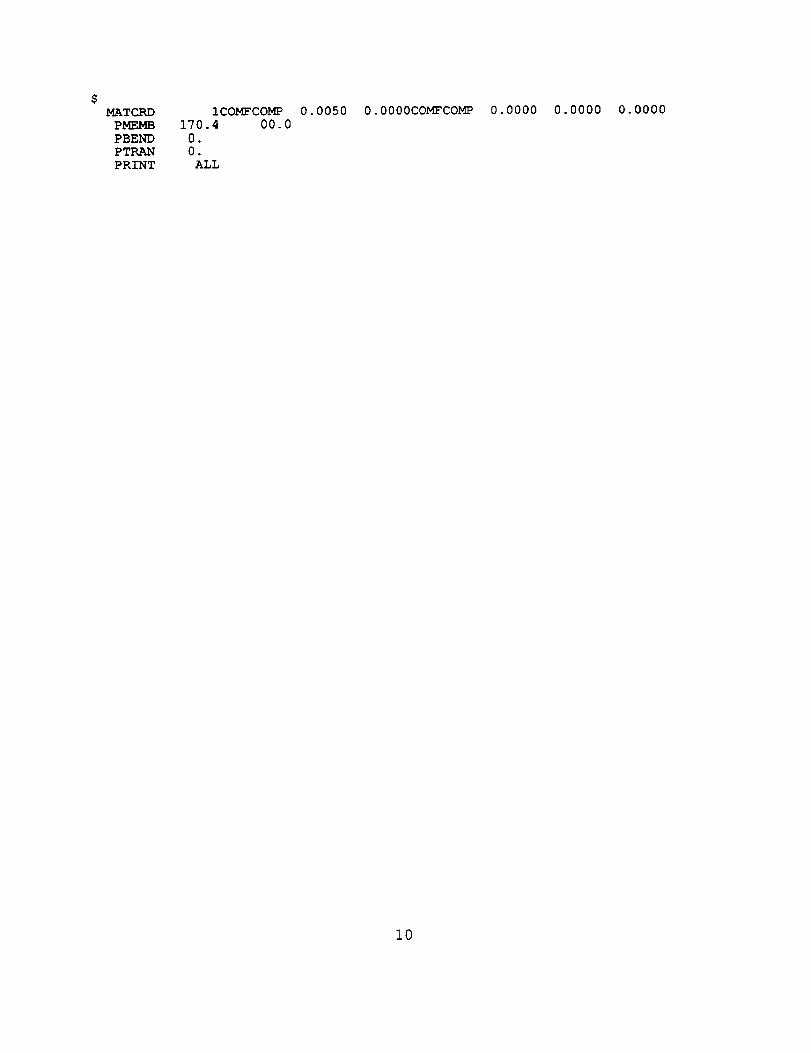
If the material system is to consist of the particulate reinforced matrix only (i.e. nocontinuous fiber), then the following procedure should be followed. For the four lettercode name for the fiber, the word uCOMF" should be entered. For the fiber volume
ratio, a positive number less than 0.01 (but greater than 0.0001) should be entered. Agood value to use is 0.0050. With this procedure, the "fiber" of the composite will thenbe assigned the properties of the particulate matrix computed earlier. This procedureis needed since the original ICAN code was written to analyze composites withcontinuous fibers, and thus a =Fiber" material must be specified and accounted for inthe input. The computed ply and laminate effective properties will then be equal to theeffective properties computed for the particulate matrix.

E.) Sample Input:
The following four sample input files are designed to show some of the codefeatures. Features of input specific to ICAN/PART are discussed below in some
detail.
Example 1: In this input, a particulate matrix composite is to be analyzed (PARTIC isset to T). The particulate matrix consists of Particulate Filler Particles (PARF) in anIntermediate Modulus High Strength Matrix. The particle volume ratio is set to 0.3
(30%), and a placeholder value of 0.05 is entered for the void volume ratio. In thematerial system, only one material system is specified, and this material system is to
consist of the particulate matrix only (no continuous fiber is present). Therefore, the"COMF" code is entered for the "Fiber', the "COMP" code is entered for the "Matrix",and a "Fiber Volume Ratio" of 0.005 is entered. Please note that temperature loads
are applied in this input by specifying differing use and cure temperatures for this ply,and that an axial membrane load is applied in the "X" direction in the mechanical load
section of the input.
ICAN verification 1 for particulate composite
COMSATCSANB
BIDE
RINDV
NONUDF
DEFECT
$$ MICRO:
$$
MICRO T
$$ PARTIC: T=Particulate Matrix Composite
$ F=Homogeneous Matrix Material
$PARTIC T
$$ Material Cards for Particulate Matrix:
$ PARF=Particle Code Name for Particulate Matrix
$ IMHS=Binder Code Name for Particulate Matrix
$ 0.3=Particle Volume Ratio$ 0.05=Void Volume Ratio (Placeholder Only)
TF
FF
T
F
T=Full Analysis of Particulate Matrix CompositeF=No Micromechanical Calculations Performed
$PARFIMHS 0.3 0.05
PLY 1 1 70.00 170.00 0.00 0.00 0.I
PLY 2 1 70.00 170.00 0.00 0.00 0.I
PLY 3 1 70.00 170.00 0.00 0.00 0.i
PLY 4 1 70.00 170.00 0.00 0.00 0.i
$$ Material Cards for Particulate Matrix Composite
$$$
COMF=Code Name for "Fiber" With Same Properties as Particulate Matrix
COMP=Code Name for Particulate Matrix
0.005="Fiber" Volume Ratio (Set Very Small Since No Continuous Fiber)
9
$MATCRDPMEMB
PBENDPTRAN
ICOMFCOMP
170.4 00.0
0.
0.
ALL
0.0050 0.0000COMFCOMP 0.0000 0.0000 0.0000
i0

Example 2: This input file is identical to the previous input file, with the exception that
only thermal loads are applied to the composite in the form of a temperature cool-down from 170 degrees F to 70 degrees F.
ICAN verification 2
COMSAT TCSANB F
BIDE F
RINDV FNONUDF T
DEFECT F
$$ MICRO :
$$
MICRO
$$ PARTIC
$$
PARTIC T
$
for particulate composite
T=Full Analysis of Particulate Matrix CompositeF=No Micromechanical Calculations Performed
T
: T=Particulate Matrix Composite
F=Homogenous Matrix Material
$ Material Cards for Particulate Matrix:$ PARF=Particle Code Name for Particulate Matrix
$ IMHS=Binder Code Name for Particulate Matrix
$ 0.3=Particle Volume Ratio$ 0.05=Void Volume Ratio (Placeholder 0nly)
$PARFIMHS 0.3 0.05
PLY 1 1 70.00 170.00 0.00 0.00 0.1
PLY 2 1 70.00 170.00 0.00 0.00 0.1PLY 3 1 70.00 170.00 0.00 0.00 0.I
PLY 4 1 70.00 170.00 0.00 0.00 0.i
$$ Material Cards for Particulate Matrix Composite$ COMF=Code Name for "Fiber" With Same Properties as Particulate Matrix
$ COMP=Code Name for Particulate Matrix$ 0.005=-Fiber" Volume Ratio (Set Very Small Since No Continuous Fiber)
$MATCKD ICOMFCOMP 0.0050 0.0000COMFCOMP 0.0000 0.0000 0.0000
PMEMB 0. 00.0
PBEND 0.
PTRAN 0.
PRINT ALL
Ii

Example 3: In this input, the particulate matrix system is the same as in the previous
two examples, but note in this case that for the composite material system, a
continuous fiber is present. A graphite fiber (AS--) with a fiber volume ratio of 0.45
(45%) has been specified in the material card definition. The fiber properties will beread in directly from the material databank and utilized along with the computed
effective properties of the particulate reinforced matrix in order to compute the overall
effective properties of the composite system. Please note that for this input deck, only
mechanical loads are applied to the composite, as the use and cure temperatures for
each ply are set to the same value (thus eliminating thermal loads).
ICAN verification 3 for particulate compositeCOMSAT T
CSANB FBIDE F
RINDV F
NONUDF T
DEFECT F
$$ MICRO :$$
MICRO T
$$ PARTIC: T=Particulate Matrix Composite
$ F=Homogeneous Matrix Material
$PARTIC T
$$ Material Cards for Particulate Matrix
$ PARF=Particle Code Name for Particulate Matrix
$ IMHS=Binder Code Name for Particulate Matrix$ 0.3=Particle Volume Ratio
$ 0.05=Void Volume Ratio (Placeholder Only)
T=Full Analysis of Particulate Matrix CompositeF=No Micromechanical Calculatzons Performed
$PARFIMHS 0.3 0.05
PLY 1 1
PLY 2 1PLY 3 1
PLY 4 1
$
70.00 70.00 0.00 0.00 0.I
70.00 70.00 0.00 0.00 0.I70.00 70.00 0.00 0.00 0.1
70.00 70.00 0.00 0.00 0.1
$ Material Cards for Particulate Matrix Composite
$ AS--=Code Name for Continuous Fiber$ COMP=Code Name for Particulate Matrix
$ 0.45=Fiber Volume Ratio (Significant Value Since Continuous Fiber)
$0.0000MATCRD IAS--COMP
PMEMB 170.4 00.0
PBEND 0.
PTRAN 0.
PRINT ALL
0.4500 0.0000AS--COMP 0.0000 0.0000
12

Example 4: For this input, the bottom ply of the composite (Ply 1) is specified to be
composed of a material with continuous graphite fibers (at a 0.45 fiber volume
fraction) reinforcing the particulate matrix. The remaining plies of the composite areset to be composed of the particulate matrix material only. In this manner a singlyreinforced beam section can be analyzed. Please note that only mechanical loads are
applied for this problem.
ICAN verification 4 for particulate composite
COMSAT T
CSANB F
BIDE F
RINDV FNONUDF T
DEFECT F
$$ MICRO :$$
MICRO
$
$ PARTIC
s$
PARTIC T
$$ Material Cards for Particulate Matrix:
$ PARF=Particle Code Name for Particulate Matrix
$ IMHS=Binder Code Name for Particulate Matrix
$ 0.3=Particle Volume Ratio$ 0.05=Void Volume Ratio (Placeholder Only)
T=Full Analysis of Particulate Matrix CompositeF=No Micromechanical Calculations Performed
T
: T=Particulate Matrix Composite
F=Homogeneous Matrix Material
70.00 70.00 0.00 0.00 0.i
70.00 70.00 0.00 0.00 0.i
70.00 70.00 0.00 0.00 0.1
70.00 70.00 0.00 0.00 0.1
$ Material Cards for Particulate Matrix Composite$ COMF=Code Name for "Fiber" With Same Properties as Particulate Matrix
$ AS--=Code Name for Continuous Graphite Fiber
$ COMP=Code Name for Particulate Matrix$ 0.005=Fiber Volume Ratio for Material With No Continuous Fiber
$ 0.45=Fiber Volume Ratio for Material With Continuous Fibers
$
$PARFIMHS 0.3 0 .05
PLY 1 2
PLY 2 1
PLY 3 1
PLY 4 1
$
0.0050 0.0000COMFCOMP 0.0000
0.4500 0.0000AS--COMP 0.0000
0.0000
0.0000
0.0000
0.0000MATCRD ICOMFCOMP
MATCRD 2AS--COMP
PMEMB 170.4 00.0
PBEND 0.PTRAN 0.
PRINT ALL
13

Code Compilation
A UNIX description file, or "Makefile", is available to facilitate the compiling andlinking process. It can be executed by simply issuing the =make = utility commandfollowed by a carriage return. The make utility will then execute, creating anexecutable version of ICAN/PART in the process. The code has been tested on aSun Sparcstation platform running the Solaris 2.4 operating system. The code hasalso been compiled and tested on a IBM/PC compatible machine running the MS/DOSVersion 6.2 operating system. On the PC platform, the code was compiled usingMicrosoft Fortran Version 5.1 and the Microsoft Fortran Powerstation (32 bit compiler).
Code Execution
The ICAN/PART code is executed in a manner typical of UNIX systems. The
executable code file, input and output files should be in the same directory.Additionally, the resident material databank must be in the same directory as theICAN/PART executable file and have the name =databk.dat". To execute the code,
the following command should be issued:
ican < input_file > output_file
where ican is the executable of the ICAN/PART computer code, input_file is the nameof the file with the input deck (can be any valid UNIX file name), output_file is thename of the file to which the output information should be written (again, can be anyvalid UNIX file name), and "<" and ">" are the UNIX input and output redirection
symbols, respectively. The code execution should take place in only a few seconds inmost cases.
OUtDUt Descriotion
The printed output from ICAN/PART is very similar to that of the original ICAN,with a few exceptions accounting for the fact that a particulate matrix composite isbeing analyzed. Again, it is assumed that the user is familiar with the original ICANcode, and only the features of the output which differ from the original ICAN will bedescribed.
Specific Features of Output
A.) Echo of Constituent Properties of Particulate and Binder:
Immediately after the detailed echo of the input deck, for a particulate matrixcomposite, the constituent properties of the particulate and binder that have been read
14
in from the material databank are echoed back to the user in an easy to read format.The format of the particulate matrix constituent property output is identical to that ofthe echo of the fiber and matrix constituent properties that is used in the original
ICAN.
B.) Output of Constituent Properties of the Material System
After the echo of the constituent properties of the particulate matrix, the constituent
properties and the computed effective properties for each material system are printedout. As in the original ICAN, the data for each material system is printed outsequentially. For a particulate matrix composite, the "matrix" properties that areprinted out are the computed effective properties of the particulate matrix. These
properties are computed from the constituent information for the particulate matrixusing the equations described in reference [1].
For the "fiber" properties, the properties that are printed out depend on whether ornot a continuous reinforcing fiber is present in the material system. If a continuous
fiber is present, the constituent properties that have been read in from the materialdatabank are echoed back in the output. If the material system has been specified as
consisting of only a particulate reinforced matrix, the "fiber" properties are thecomputed effective properties of the particulate matrix, placed into the proper format
(with the assumption that the "fiber" is isotropic).
After the constituent data for the material system is output, the overall effective
properties for the material system are printed out. These properties are computedusing the same micromechanical equations that were developed for the original ICAN[2]. The only difference for ICAN/PART is that the "matrix" properties that are used inthe equations are actually the computed effective properties of the particulatereinforced matrix. For a case where the material system consists of only a particulatereinforced matrix, since the "fiber" and "matrix" properties are both set to be the
computed effective properties of the particulate matrix, the computed properties of theoverall material system will be equal to those of the particulate reinforced matrix
system.
C.) Output of Ply Microstresses:
The output of the ply microstresses is the same as in the original ICAN. However,there are some specific issues relating to the analysis of particulate matrix composites.First, the matrix microstresses that are output are "smeared" matrix microstresses thathave not been broken down into particulate or binder microstresses. For a casewhere no continuous fiber is present in the material system, the "A" and "B" regionmatrix stresses, along with the 'fiber" and "matrix" stresses, are all equal since the
material system is all matrix. The ICAN User's Manual [2] has a full description ofhow the ply microstresses are broken up into "A" and "B" regions. In the case where
15

continuous fibers are not present in the composite, in the terminology of the originalICAN code, the matrix stresses in the "A" region of the composite are assumed to bethe "true" matrix microstresses. In the case where a continuous fiber is present in the
material system, the fiber stresses are the actual stresses that are present in the fiber.The "matrix" stresses are still "smeared" stresses, but the stresses will be legitimatelydifferent in the "A= and "B" regions of the composite, and both sets of stresses mustbe considered.
To break down the "matrix" stresses into particle and binder microstresses, the
stresses are summed up and utilized in the equations described in reference [1] as theapplied stresses. The mechanical, thermal and moisture stresses are all summedtogether for each component direction. For example, the 1-1 'matrix = microstress dueto longitudinal loading, the 1-1 stress due to transverse loading, the 1-1 stress due tothermal loading and the 1-1 stress due to moisture loading are all summed togetherand considered to be the overall 1-1 mechanical load in the =matrix'. If no continuous
fiber is present in the material system, only the =matrix' stresses in the =A= region aresummed and utilized. If continuous fibers are present in the material system, the"matrix" stresses in the "A" and 'B" regions are both used, but they are summed and
utilized separately since the stress states in the two regions are different. Thetemperature and moisture gradient that are applied to the ply are also assumed to beapplied to the =matrix", and are utilized in the equations described in reference [1].
D.) Output of Particulate Matrix Microstresses:
After the printout of the ply microstresses, the microstress information for theconstituents of the particulate matrix is printed out for each ply. The 1-1, 2-2, 3-3, 1-2,1-3 and 2-3 component stresses for the binder and the particle are printed out, alongwith the Von Mises stress for the particle and the binder. If no continuous fiber is
present in the material system for a_By.of the plies, only the "A" region stresses areprinted out. If continuous fibers are present in a_D,y,of the plies, both "A" and "B=region stresses are printed out. However, if for any of the plies no continuous fibers
are present, the "A" and "B" region stresses are set equal for these plies.
If thermal or moisture stresses are present, the stresses due to thermal and/or
moisture loading are summed into the stresses due to mechanical loading, and thestresses are printed out as one combined value. For example, what is printed out asthe 1-1 stress in the binder is actually the sum of the 1-1 stress due to mechanicalloading, the 1-1 stress due to thermal loading (the applied temperature gradient), andthe 1-1 stress due to moisture (the applied moisture gradient).
An important point to note is that for each of the component directions, the bindermaterial that is directly in front of the particle is assumed to have the same stressstate as the particle. Also, the stresses are assumed to be constant in the particleand binder, and to be equal to the "average" stress in the region.
16
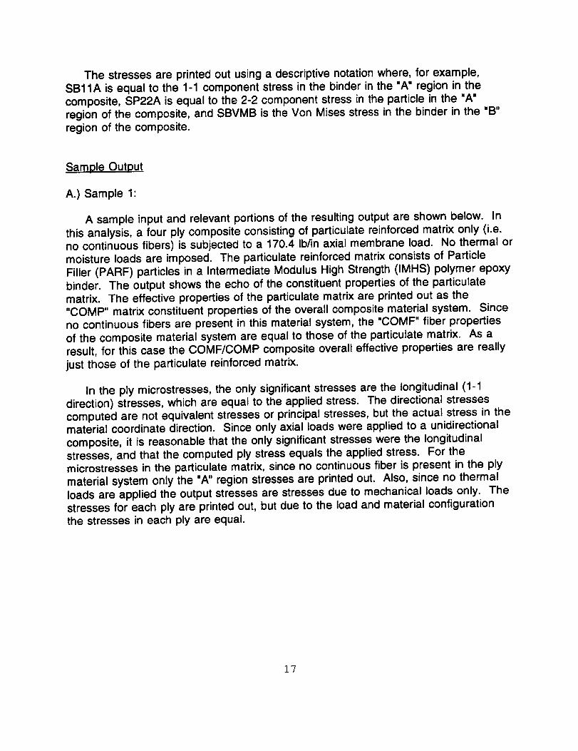
The stresses are printed out using a descriptive notation where, for example,
SB11A is equal to the 1-1 component stress in the binder in the "A" region in the
composite, SP22A is equal to the 2-2 component stress in the particle in the "A"
region of the composite, and SBVMB is the Von Mises stress in the binder in the "B"
region of the composite.
Sample Output
A.) Sample 1:
A sample input and relevant portions of the resulting output are shown below. In
this analysis, a four ply composite consisting of particulate reinforced matrix only (i.e.no continuous fibers) is subjected to a 170.4 Ib/in axial membrane load. No thermal or
moisture loads are imposed. The particulate reinforced matrix consists of Particle
Filler (PARF) particles in a Intermediate Modulus High Strength (IMHS) polymer epoxy
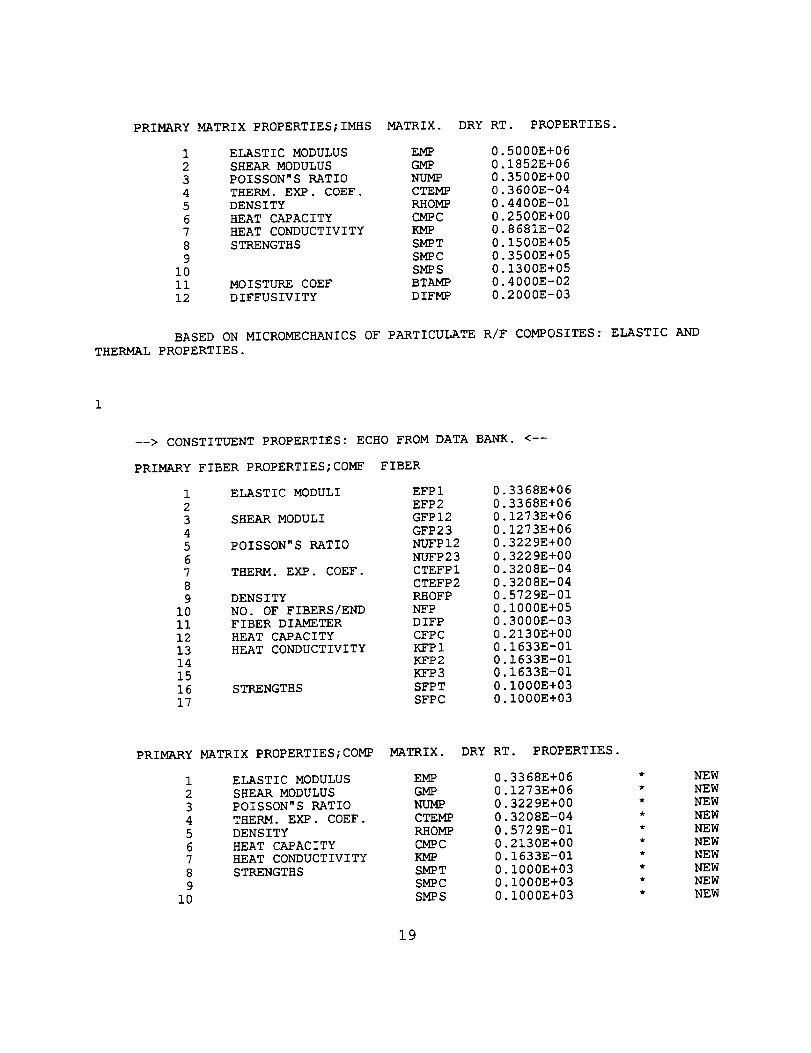
binder. The output shows the echo of the constituent properties of the particulate
matrix. The effective properties of the particulate matrix are printed out as the"COMP" matrix constituent properties of the overall composite material system. Since
no continuous fibers are present in this material system, the "COMF" fiber properties
of the composite material system are equal to those of the particulate matrix. As aresult, for this case the COMF/COMP composite overall effective properties are really
just those of the particulate reinforced matrix.
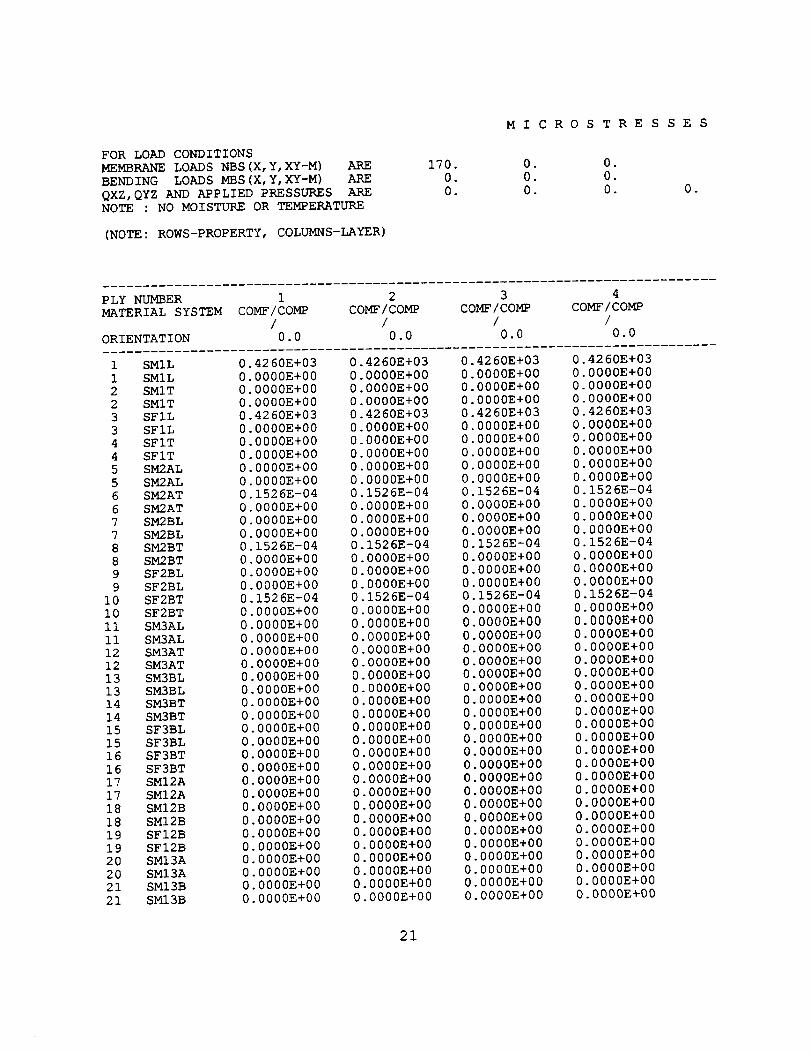
In the ply microstresses, the only significant stresses are the longitudinal (1-1
direction) stresses, which are equal to the applied stress. The directional stresses
computed are not equivalent stresses or principal stresses, but the actual stress in thematerial coordinate direction. Since only axial loads were applied to a unidirectional
composite, it is reasonable that the only significant stresses were the longitudinalstresses, and that the computed ply stress equals the applied stress. For themicrostresses in the particulate matrix, since no continuous fiber is present in the ply
material system only the "A" region stresses are printed out. Also, since no thermal
loads are applied the output stresses are stresses due to mechanical loads only. Thestresses for each ply are printed out, but due to the load and material configuration
the stresses in each ply are equal.
17

ICAN verification 1 for particulate compositeCOMSAT T
CSANB F
BIDE F
RINDV F
NONUDF T
DEFECT FMICRO T
PARTIC T
PARFIM_HS 0.3 0.05
PLY 1 1PLY 2 1
PLY 3 1PLY 4 1
MATCRD ICOMFCOMP
PMEMB 170.4 00.0
PBEND 0.
PTRAN 0.
PRINT ALL
70.00 70.00 0.00 0.00 0.i
70.00 70.00 0.00 0.00 0.i
70.00 70.00 0.00 0.00 0.1
70.00 70.00 0.00 0.00 0.1
0.0050 0.0000COMFCOMP 0.0000 0.0000 0.0000
ECHO OF CONSTITUENT PROPERTIES OF PARTICLE REINFORCED MATRIX
PARTICLE VOLUME RATIO - 0.300 MATRIX VOLUME RATIO - 0.700
VOID VOLUME RATIO - 0.050
--> CONSTITUENT PROPERTIES: ECHO FROM DATA BANK. <--
PRIMARY PARTICLE PROPERTIES;PARF PARTICLE
1 ELASTIC MODULI EFPI
2 EFP23 SHEAR MODULI GFPI2
4 GFP23
5 POISSON"S RATIO NUFPI2
6 NUFP23
7 THERM. EXP. COEF. CTEFPI
8 CTEFP2
9 DENSITY RHOFP
I0 NO. OF FIBERS/END NFPii FIBER DIAMETER DIFP
12 HEAT CAPACITY CFPC
13 HEAT CONDUCTIVITY KFPI14 KFP2
15 KFP3
16 STRENGTHS SFPT
17 SFPC
0 1000E+06
0 1000E+060 4170E+05
0 4170E+050 2000E+00
0 2000E+00
0.3600E-05
0 3600E-05
0 8830E-01
0 1000E+050 3000E-03
0 1700E+00
0 8680E+000 8680E+00
0 8680E+00
0 2800E+06
0 2000E+06
18
PRIMARY MATRIX PROPERTIES;IMHS MATRIX. DRY RT. PROPERTIES.
1 ELASTIC MODULUS EMP 0.5000E+06
2 SHEAR MODULUS GMP 0.1852E+06
3 POISSON"S RATIO NUMP 0.3500E+00
4 THEBIM. EXP. COEF. CTEMP 0.3600E-04
5 DENSITY RHOMP 0.4400E-01
6 HEAT CAPACITY CMPC 0.2500E+007 HEAT CONDUCTIVITY KMP 0.8681E-02
8 STRENGTHS SMPT 0.1500E+05
9 SMPC 0.3500E+05
i0 SMPS 0.1300E+05
ii MOISTURE COEF BTAMP 0.4000E-02
12 DIFFUSIVITY DIFMP 0.2000E-03
BASED ON MICROMECHANICS OF PARTICULATE R/F COMPOSITES: ELASTIC AND
THERMAL PROPERTIES.
--> CONSTITUENT PROPERTIES: ECHO FROM DATA BANK. <--
PRIMARY FIBER PROPERTIES;COMF FIBER
1 ELASTIC MODULI EFPI 0.3368E+06
2 EFP2 0.3368E+06
3 SHEAR MODULI GFPI2 0.1273E+064 GFP23 0.1273E+06
5 POISSON"S RATIO NUFPI2 0.3229E+00
6 NUFP23 0.3229E+007 THERM. EXP. COEF. CTEFPI 0.3208E-04
8 CTEFP2 0.3208E-04
9 DENSITY RHOFP 0.5729E-01
i0 NO. OF FIBERS/END NFP 0.1000E+05ii FIBER DIAMETER DIFP 0.3000E-03
12 HEAT CAPACITY CFPC 0.2130E+00
13 HEAT CONDUCTIVITY KFPI 0.1633E-0114 KFP2 0.1633E-01
15 KFP3 0.1633E-01
16 STRENGTHS SFPT 0.1000E+03
17 SFPC 0.1000E+03
PRIMARY MATRIX PROPERTIES;COMP MATRIX. DRY RT. PROPERTIES.
1 ELASTIC MODULUS EMP 0.3368E+06
2 SHEAR MODULUS GMP 0.1273E+06
3 POISSON"S RATIO NUMP 0.3229E+004 THERM. EXP. COEF. CTF__ 0.3208E-04
5 DENSITY RHOMP 0.5729E-01
6 HEAT CAPACITY CMPC 0.2130E+007 HEAT CONDUCTIVITY KMP 0.1633E-01
8 STRENGTHS SMPT 0.I000E+03
9 SMPC 0.1000E+03
10 SMPS 0.I000E+03
NEW
NEW
NEW
NEW
NEW
NEW
NEW
NEWNEW
NEW
19

Ii MOISTURE COEF BTAMP 0.4000E-02 * NEW
12 DIFFUSIVITY DIFMP 0.2000E-03 * NEW
PRIMARY COMPOSITE PROPERTIES;COMF/COMP
BASED ON MICROMECHANICS OF INTRAPLY HYBRID COMPOSITES: ELASTIC AND
THERMAL PROPERTIES.
FIBER VOLUME RATIO - 0.005
VOID VOLUME RATIO - 0.000
MATRIX VOLUME RATIO - 0.995
1 ELASTIC MODULI EPCI 0.2 EPC2 0.
3 EPC3 0.
4 SHEAR MODULI GPCI2 0.
5 GPC23 0.
6 GPCI3 0.
7 POISSON"S RATIO NUPCI2 0.
8 NUPC23 0.9 NUPCI3 0.
i0 THERM. EXP. COEF. CTEPCI 0.
ii CTEPC2 0.12 CTEPC3 0.
13 DENSITY RHOPC 0.14 HEAT CAPACITY CPC 0.
15 HEAT CONDUCTIVITY KPCI 0
16 KPC2 0
17 KPC3 0
18 STRENGTHS SPCIT 0
19 SPCIC 020 SPC2T 0
21 SPC2C 0
22 SPCI2 0
23 MOIST. DIFFUSIVITY DPCI 0
24 DPC2 0
25 DPC3 026 MOIST. EXP. COEF. BTAPCI 0
27 BTAPC2 0
28 BTAPC3 029 FLEXUKAL MODULI EPCIF 0
30 EPC2F 0
31 STRENGTHS SPC23 032 SPClF 0
33 SPC2F 034 SPCSB 0
35 PLY THICKNESS TPC 0
36 INTERPLY THICKNESS PLPC 037 INTERFIBER SPACING PLPCS 0
3368E+06
3368E+06
3368E+06
1273E+06
1273E+06
1273E+06
3229E+003229E+00
3229E+00
3208E-043208E-04
3208E-04
5729E-01
2130E+00
1633E-01
1633E-01
1633E-015000E+00
5000E+00
1000E+03
1000E+03
1000E+031990E-03
1859E-03
1859E-03
3980E-02
3723E-023723E-02
3368E+063368E+06
1000E+03
6250E+00
1250E+03
1500E+03
5000E-023460E-02
3460E-02
20
FOR LOAD CONDITIONSMEMBRANE LOADS NBS (X, Y, XY-M) ARE
BENDING LOADS MBS (X, Y, XY-M) ARE
QXZ, QYZ AND APPLIED PRESSURES ARENOTE : NO MOISTURE OR TEMPERATURE
(NOTE: ROWS-PROPERTY, COLUMNS-LAYER)
170.
0.
0.
M ICRO
.
0.0.
STRE
0o
0.
0.
SSES
0°
PLY NUMBER 1 2
MATERIAL SYSTEM COMF/COMP COMF/COMP/ /
ORIENTATION 0.0 0.0
3
COMF /COMP
/
0.0
4
COMF /COMP
/
0.0
1 SMIL 0.4260E+03 0.4260E+03
1 SMIL 0.0000E+00 0.0000E+00
2 SMIT 0.0000E+00 0.0000E+00
2 SMIT 0.0000E+00 0.0000E+003 SFIL 0.4260E+03 0.4260E+03
3 SFIL 0.0000E+00 0.0000E+00
4 SFIT 0.0000E+00 0.0000E+00
4 SFIT 0.0000E+00 0.0000E+00
5 SM2AL 0.0000E+00 0.0000E+00
5 SM2AL 0.0000E+00 0.0000E+006 SM2AT 0.1526E-04 0.1526E-04
6 SM2AT 0.0000E+00 0.0000E+00
7 SM2BL 0.0000E+00 0.0000E+00
7 SM2BL 0.0000E+00 0.0000E+00
8 SM2BT 0.1526E-04 0.1526E-04
8 SM2BT 0.0000E+00 0.0000E+009 SF2BL 0.0000E+00 0.0000E+00
9 SF2BL 0.0000E+00 0.0000E+00
i0 SF2BT 0.1526E-04 0.1526E-04
I0 SF2BT 0.0000E+00 0.0000E+00
II SM3AL 0.0000E+00 0.0000E+00
ii SM3AL 0.0000E+00 0.0000E+0012 SM3AT 0.0000E+00 0.0000E+00
12 SM3AT 0.0000E+00 0.0000E+00
13 SM3BL 0.0000E+00 0.0000E+00
13 SM3BL 0.0000E+00 0.0000E+0014 SM3BT 0.0000E+00 0.0000E+00
14 SM3BT 0.0000E+00 0.0000E+00
15 SF3BL 0.0000E+00 0.0000E+0015 SF3BL 0.0000E+00 0.0000E+00
16 SF3BT 0.0000E+00 0.0000E+00
16 SF3BT 0.0000E+00 0.0000E+00
17 SMI2A 0.0000E+00 0.0000E+00
17 SMI2A 0.0000E+00 0.0000E+00
18 SMI2B 0.0000E+00 0.0000E+00
18 SMI2B 0.0000E+00 0.0000E+00
19 SFI2B 0.0000E+00 0.0000E+00
19 SFI2B 0.0000E+00 0.0000E+0020 SMI3A 0.0000E+00 0.0000E+00
20 SMI3A 0.0000E+00 0.0000E+00
21 SMI3B 0.0000E+00 0.0000E+00
21 SMI3B 0.0000E+00 0.0000E+00
0.4260E+03
0.0000E+000.0000E+00
0.0000E+00
0.4260E+03
0.0000E+000.0000E+00
0.0000E+00
0.0000E+00
0.0000E+00
0.1526E-04
0.0000E+00
0.0000E+00
0.0000E+000.1526E-04
0.0000E+00
0.0000E+000.0000E+00
0.1526E-04
0.0000E+00
0.0000E+00
0.0000E+00
0.0000E+000.0000E+00
0.0000E+00
0.0000E+000.0000E+00
0.0000E+00
0.0000E+00
0.0000E+000.0000E+00
0.0000E+00
0.0000E+00
0.0000E+00
0.0000E+00
0.0000E+00
0.0000E+00
0.0000E+000.0000E+00
0.0000E+00
0.0000E+00
0.0000E+00
0.4260E+030.0000E+00
0.0000E+00
0.0000E+00
0.4260E+03
0.0000E+000.0000E+00
0 0000E+00
0 0000E+00
0 0000E+00
0 1526E-04
0 0000E+000 0000E+00
0.0000E+000.1526E-04
0.0000E+00
0.0000E+000.0000E+00
0.1526E-04
0.0000E+00
0.0000E+00
0.0000E+00
0.0000E+000.0000E+00
0.0000E+00
0.0000E+000.0000E+00
0.0000E+00
0.0000E+00
0.0000E+000.0000E+00
0.0000E+00
0.0000E+00
0.0000E+00
0.0000E+00
0.0000E+00
0.0000E+00
0.0000E+000.0000E+00
0.0000E+00
0.0000E+00
0.0000E+00
21

22
2223
2324
24
25
25
42
4243
4344
44
45
45
46
46
SFI3B
SFI3BSM23A
SM23ASM23B
SM23B
SF23B
SF23B
SI22BSI22B
SI33B
SI33B
SII2B
SII2B
S INC
S INC
SISC
SISC
0.0000E+00 0.0000E+00 0.0000E+00 0.0000E+00
0.0000E+00 0.0000E+00 0.0000E+00 0.0000E+00
0.0000E+00 0.0000E+00 0.0000E+00 0.0000E+00
0.0000E+00 0.0000E+00 0.0000E+00 0.0000E+000.0000E+00 0.0000E+00 0.0000E+00 0.0000E+00
0.0000E+00 0.0000E+00 0.0000E+00 0.0000E+00
0.0000E+00 0.0000E+00 0.0000E+00 0.0000E+00
0.0000E+00 0.0000E+00 0.0000E+00 0.0000E+00
0.1526E-04 0.1526E-04 0.1526E-04 0.1526E-04
0.0000E+00 0.0000E+00 0.0000E+00 0.0000E+000.0000E+00 0.0000E+00 0.0000E+00 0.0000E+00
0.0000E+00 0.0000E+00 0.0000E+00 0.0000E+000.0000E+00 0.0000E+00 0.0000E+00 0.0000E+00
0.0000E+00 0.0000E+00 0.0000E+00 0.0000E+00
0.1526E-04 0.1526E-04 0.1526E-04 0.1526E-04
0.0000E+00 0.0000E+00 0.0000E+00 0.0000E+00
-0.1526E-04 -0.1526E-04 -0.1526E-04 -0.1526E-04
0.0000E+00 0.0000E+00 0.0000E+00 0.0000E+00
NOTATION: S --- STRESS (SIGMA)M --- MATRIX , F --- FIBER AND I --- INTERFACE
1,2,3 --- DIRECTIONS FOR STRESSES - PLY MATERIAL AXES
L,T --- DIRECTIONS OF PLY STRESSESA --- REGION CONTAINING NO FIBERS
B --- REGION CONTAINING FIBERS AND MATRIX
EXAMPLE: SM2AL STANDS FOR TRANSVERSE NORMAL STRESSIN REGION A DUE TO A LOAD IN THE LONGITUDINAL
DIRECTION
22

PARTICULATE MATRIX
MI CR0 STRE S SE S
OVERALL MATRIX STRESS IN EACH PLY IS THE SUM OF THE
MECHANICAL, THERMAL AND MOISTURE STRESSES
COMPUTED ABOVE
NOTE: NO THERMAL OR MOISTURE STRESSES ARE PRESENT
IF PRESENT, THERMAL AND MOISTURE STRESSES ARESUMMED INTO II, 22, AND 33 STRESS COMPONENTS
(NOTE: ROWS-PROPERTY, COLUMNS-LAYER)
PLY NUMBER 1 2 3
1 SBIIA
3 SB22A5 SB33A
7 SBI2A
9 SBI3Aii SB23A
13 SBVMA
15 SPIIA
17 SP22A
19 SP33A
21 SPI2A
23 SPI3A
25 SP23A
27 SPVMA
0-0-0
0000
0.6323E+03
0.1714E+02
0.1714E+02
0.0000E+000.0000E+00
0.0000E+00
0 6152E+031719E+03
1260E+02
1260E+020000E+00
0000E+00
0000E+00
1845E+03
0.6323E+03
0.1714E+02
0.1714E+02
0.0000E+000.0000E+00
0 0000E+00
0 6152E+03
0 1719E+03
-0 1260E+02
-0 1260E+020 0000E+00
00000E+000.0000E+00
0.1845E+03
0.6323E+03
0.1714E+02
0.1714E+02
0.0000E+000.0000E+00
0.0000E+00
0.6152E+03
0.1719E+03-0.1260E+02
-0.1260E+020.0000E+00
0.0000E+00
0.0000E+00
0.1845E+03
0.6323E+03
0.1714E+020.1714E+02
0.0000E+00
0.0000E+00
0.0000E+00
0.6152E+03
0.1719E+03-0.1260E+02
-0.1260E+02
0.0000E+00
0.0000E+00
0.0000E+00
0.1845E+03
NOTATION: S --- STRESS (SIGMA)B--BINDER, P--- PARTICLE
VM --- V0N MISES STRESS
IF PARTICULATE COMPOSITE HAS SIGNIFICANT CONTINUOUS
FIBER, STRESSES ARE BROKEN UP INTO A AND B REGIONSFROM ABOVE. IF SIGNIFICANT CONTINUOUS FIBER IS
NOT PRESENT, A AND B REGION STRESSES ARE EQUAL
STRESSES IN BINDER REGIONS IN FRONT OF PARTICLEARE ASSUMED TO BE EQUAL TO THE PARTICLE STRESSES
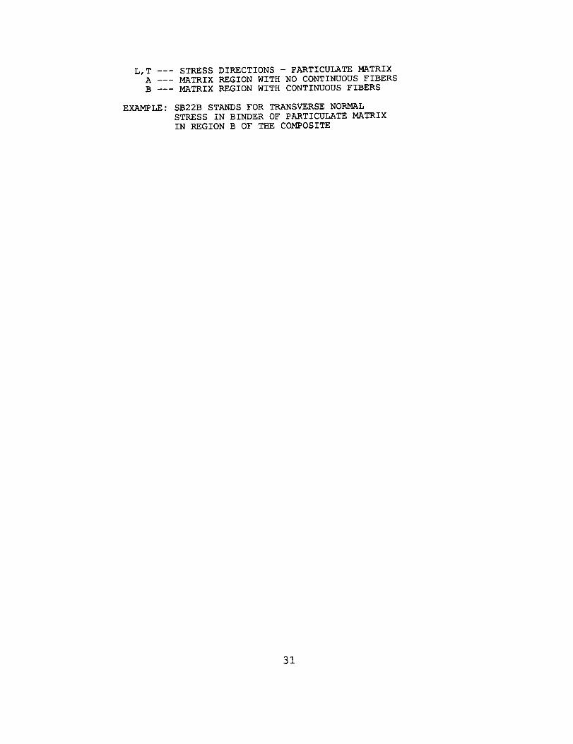
1,2,3 --- STRESS DIRECTIONS - PLY MATERIAL AXESL,T --- STRESS DIRECTIONS - PARTICULATE MATRIX
A MATRIX REGION WITH NO CONTINUOUS FIBERS
B --- MATRIX REGION WITH CONTINUOUS FIBERS
E_LE : SB22B STANDS FOR TRANSVERSE NORMALSTRESS IN BINDER OF PARTICULATE MATRIX
IN REGION B OF THE COMPOSITE
23

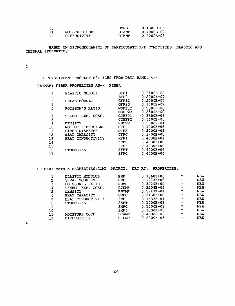
B.) Sample 2:
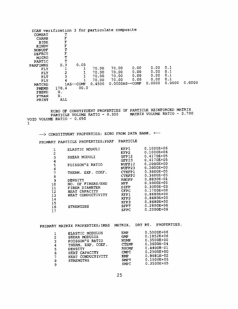
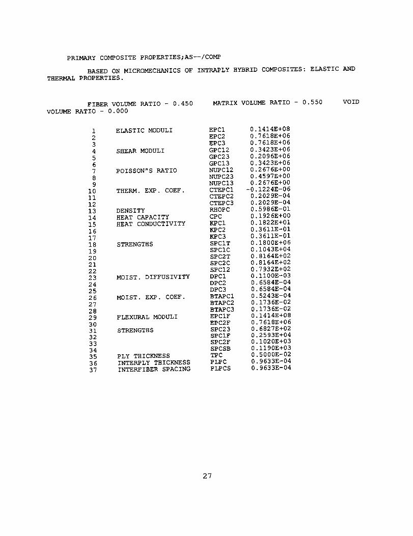
The sample input and relevant portions of the resulting output are shown below.This analysis is similar to the previous example, except that continuous graphite fibers(at 45% volume fraction) are present in the material system along with the particulatereinforced matrix. For this example, the effective properties of the particulate matrix
are again computed and printed out as the properties of the "COMP" matrixconstituent of the material system. Unlike the previous example, since in this casecontinuous reinforcing fibers are present in the overall material system, the actual fiber
properties are echoed back from the databank in the ply material system definition.The effective properties for the AS--/COMP material system are the actual effectiveproperties obtained by combining the AS-- fiber with the particulate reinforced matrix.
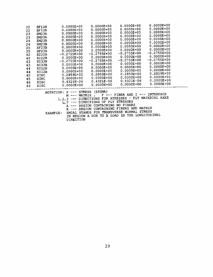
Due to the presence of continuous reinforcing fibers in the material system,distinct fiber and "matrix" constituent stresses are present in the ply microstresses.The transverse "matrix" stresses in the 'A" and "B" regions also differ from each otherdue the presence of the continuous fibers. In the particulate matrix microstresses,since the "smeared" matrix stresses are different in the "A" and "B" regions of the
overall composite, the microstresses in the particle and binder need to be computedfor both regions of the overall composite. Note that since no thermal or moisturestresses were applied to the composite, the output stresses are due to mechanicalloads only.
24
ICAN verification 3 for particulate composite
COMSAT T
CSANB F
BIDE F
RINDV F
NONUDF TDEFECT F
MICRO T
PARTIC TPARFIMHS 0.3 0.05
PLY 1 1
PLY 2 1
PLY 3 1
PLY 4 1
MATCRD IAS--COMP
PMEMB 170.4 00.0
PBEND 0.PTRAN 0.
PRINT ALL
70.00 70.00 0.00 0.00 0.i
70.00 70.00 0.00 0.00 0.i
70.00 70.00 0.00 0.00 0.i
70.00 70.00 0.00 0.00 0.i0.4500 0.0000AS--COMP 0.0000 0.0000 0.0000
ECHO OF CONSTITUENT PROPERTIES OF PARTICLE REINFORCED MATRIX
PARTICLE VOLUME RATIO - 0.300 MATRIX VOLUME RATIO - 0.700
VOID VOLUME RATIO - 0.050
1
--> CONSTITUENT PROPERTIES: ECHO FROM DATA BANK. <--
PRIMARY PARTICLE PROPERTIES;PARF PARTICLE
1 ELASTIC MODULI EFPI
2 EFP2
3 SHEAR MODULI GFPI2
4 GFP23
5 POISSON"S RATIO NUFPI2
6 NUFP237 THERM. EXP. COEF. CTEFPI
8 CTEFP2
9 DENSITY RHOFP
i0 NO. OF FIBERS/END NFPII FIBER DIAMETER DIFP
12 HEAT CAPACITY CFPC
13 HEAT CONDUCTIVITY KFPI14 KFP2
15 KFP3
16 STRENGTHS SFPT
17 SFPC
0.I000E+060.1000E+06
0 4170E+05
0 4170E+05
0 2000E+00
0 2000E+00
0 3600E-05
0 3600E-05
0 8830E-010 1000E+05
0 3000E-0301700E+00
0.8680E+00
0.8680E+000.8680E+00
0.2800E+06
0.2000E+06
PRIMARY
1
2
3
4
5
6
7
8
9
MATRIX PROPERTIES;IMHS MATRIX.
ELASTIC MODULUS EMP
SHEAR MODULUS GMP
POISSON"S RATIO NUMP
THERM. EXP. COEF. CTEMP
DENSITY RHOMP
HEAT CAPACITY CMPC
HEAT CONDUCTIVITY KMP
STRENGTHS SMPTSMPC
DRY RT. PROPERTIES.
0.5000E+060.1852E+06
0.3500E+000.3600E-04
0.4400E-01
0.2500E+00
0.8681E-020.1500E+05
0.3500E+05
25
i0 SMPS 0.1300E+05ii MOISTURE COEF BTAMP 0.4000E-02
12 DIFFUSIVITY DIFMP 0.2000E-03
BASED ON MICROMECHANICS OF PARTICULATE R/F COMPOSITES: ELASTIC AND
THERMAL PROPERTIES.
--> CONSTITUENT PROPERTIES: ECHO FROM DATA BANK. <--
PRIMARY FIBER PROPERTIES;AS-- FIBER
1 ELASTIC MODULI EFPI 0.3100E+08
2 EFP2 0.2000E+07
3 SHEA/% MODULI GFPI2 0.2000E+07
4 GFP23 0.I000E+07
5 POISSON"S RATIO NUFPI2 0.2000E+006 NUFP23 0.2500E+00
7 THERM. EXP. COEF. CTEFPI -0.5500E-06
8 CTEFP2 0.5600E-05
9 DENSITY RHOFP 0.6300E-01i0 NO. OF FIBERS/END NFP 0.I000E+05
ii FIBER DIAMETER DIFP 0.3000E-03
12 HEAT CAPACITY CFPC 0.1700E+00
13 HEAT CONDUCTIVITY KFPI 0.4030E+01
14 KFP2 0.4030E+00
15 KFP3 0.4030E+0016 STRENGTHS SFPT 0.4000E+06
17 SFPC 0.4000E+06
PRIMARY MATRIX PROPERTIES;COMP MATRIX. DRY RT. PROPERTIES.
1 ELASTIC MODULUS EMP 0.3368E+062 SHEAR MODULUS GMP 0.1273E+06
3 POISSON"S RATIO NUMP 0.3229E+004 THERM. EXP. COEF. CTEMP 0.3208E-04
5 DENSITY RHOMP 0.5729E-01
6 HEAT CAPACITY CMPC 0.2130E+007 HEAT CONDUCTIVITY KMP 0.1633E-01
8 STRENGTHS SMPT 0.1000E+039 SMPC 0.1000E+03
i0 SMPS 0.1000E+03
ii MOISTURE COEF BTAMP 0.4000E-02
12 DIFFUSIVITY DIFMP 0.2000E-03
NEW
NEW
NEWNEW
NEW
NEW
NEWNEW
NEW
NEW
NEW
NEW
26
PRIMARY COMPOSITE PROPERTIES;AS--/COMP
BASED ON MICROMECHANICS OF INTRAPLY HYBRID COMPOSITES: ELASTIC AND
THERMAL PROPERTIES.
FIBER VOLUME RATIO - 0.450
VOLUME RATIO - 0. 000
MATRIX VOLUME RATIO - 0.550 VOID
1 ELASTIC MODULI EPCI 0.1414E+08
2 EPC2 0.7618E+06
3 EPC3 0.7618E+06
4 SHEAR MODULI GPCI2 0.3423E+06
5 GPC23 0.2096E+06
6 GPCI3 0.3423E+067 POISSON"S RATIO NUPCI2 0.2676E+00
8 NUPC23 0.4597E+00
9 NUPCI3 0.2676E+00
10 THERM. EXP. COEF. CTEPCI -0.1224E-06
II CTEPC2 0.2029E-04
12 CTEPC3 0.2029E-0413 DENSITY RHOPC 0.5986E-01
14 HEAT CAPACITY CPC 0.1926E+0015 HEAT CONDUCTIVITY KPCI 0.1822E+01
16 KPC2 0.3611E-01
17 KPC3 0.3611E-01
18 STRENGTHS SPCIT 0.1800E+06
19 SPCIC 0.I043E+04
20 SPC2T 0.8164E+0221 SPC2C 0.8164E+02
22 SPCI2 0.7932E+02
23 MOIST. DIFFUSIVITY DPCI 0.1100E-03
24 DPC2 0.6584E-04
25 DPC3 0.6584E-04
26 MOIST. EXP. COEF. BTAPCI 0.5243E-0427 BTAPC2 0.1736E-02
28 BTAPC3 0.1736E-02
29 FLEXURAL MODULI EPCIF 0.1414E+0830 EPC2F 0.7618E+06
31 STRENGTHS SPC23 0.6827E+02
32 SPCIF 0.2593E+0433 SPC2F 0.1020E+03
34 SPCSB 0.I190E+0335 PLY THICKNESS TPC 0.5000E-02
36 INTERPLY THICKNESS PLPC 0.9633E-04
37 INTERFIBER SPACING PLPCS 0.9633E-04
27

FOR LOAD CONDITIONS
MEMBRANE LOADS NBS (X, Y, XY-M) AREBENDING LOADS MBS (X, Y, XY-M) ARE
QXZ,QYZ AND APPLIED PRESSURES ARENOTE : NO MOISTURE OR TEMPERATURE
(NOTE : ROWS-PROPERTY, COLUMNS-LAYER)
170.
0.
0.
M I C R
0o
0.
0.
OSTRE
°
0.
0.
S S E S
.
PLY NUMBER 1 2MATERIAL SYSTEM AS--/COMP AS--/COMP
/ /
ORIENTATION 0.0 0.0
3
AS--/COMP
/0.0
4
AS--/COMP
/0.0
1 SMIL
1 SMIL
2 SMIT
2 SMIT3 SFIL
3 SFIL4 SFIT
4 SFIT
5 SM2AL
5 SM2AL
6 SM2AT6 SM2AT
7 SM2BL
7 SM2BL
8 SM2BT
8 SM2BT
9 SF2BL
9 SF2BL
i0 SF2BTi0 SF2BT
ii SM3AL
ii SM3AL
12 SM3AT12 SM3AT
13 SM3BL
13 SM3BL
14 SM3BT
14 SM3BT15 SF3BL
15 SF3BL
16 SF3BT
16 SF3BT
17 SMI2A
17 SMI2A
18 SMI2B
18 SMI2B
19 SFI2B19 SFI2B
20 SMI3A
20 SMI3A21 SMI3B
21 SMI3B
0.I015E+020.0000E+00
-0.3505E-08
0.0000E+00
0.9343E+030.0000E+00
0.1588E-08
0.0000E+000.5614E+00
0.0000E+00
-0.2583E-06
0.0000E+00
-0.2755E+00
0.0000E+00
-0.5841E-06
0.0000E+00
-0.2755E+000.0000E+00
-0.5841E-06
0.0000E+000.5614E+00
0.0000E+00
0.2885E-07
0.0000E+00
-0 2755E+000 0000E+00
-0 1416E-07
0 0000E+00
-0 2755E+00
0 0000E+00
-0 1416E-070 0000E+00
0 0000E+00
0.0000E+000.0000E+00
0. 0000E+00
0.0000E+00
0.0000E+000.0000E+00
0.0000E+00
0.0000E+00
0.0000E+00
0.I015E+02
0.0000E+00
-0.3505E-08
0.0000E+00
0.9343E+030.0000E+000.1588E-08
0 0000E+000 5614E+00
0 0000E+00
-0 2583E-06
0 0000E+00
-0 2755E+000 0000E+00
-0 5841E-06
0.0000E+00
-0.2755E+00
0.0000E+00
-0.5841E-060.0000E+00
0.5614E+00
0.0000E+00
0.2885E-070.0000E+00
-0.2755E+00
0.0000E+00
-0.1416E-07
0.0000E+00-0 2755E+00
0 0000E+00
-0 1416E-07
0 0000E+00
0 0000E+00
0 0000E+00
0.0000E+00
0.0000E+000.0000E+00
0.0000E+00
0.0000E+00
0.0000E+00
0.0000E+00
0.0000E+00
0
0
-0
00
00
0
0
0
-00
-0
0
-0
0
-0
0
-00
0
0
0
0
-0
0
-00
-0
0
-0
0
0
0
0
00
0
0
00
0
.I015E+02
.0000E+00
.3505E-08
.0000E+00
.9343E+03
.0000E+00
.1588E-08
.0000E+00
.5614E+00
.0000E+00
.2583E-06
.0000E+00
.2755E+00
.0000E+00
.5841E-06
.0000E+00
.2755E+00
.0000E+00
.5841E-06
.0000E+00
.5614E+00
.0000E+00
.2885E-07
.0000E+00
.2755E+00
.0000E+00
.1416E-07
.0000E+00
.2755E+00
.0000E+00
.1416E-07
.0000E+00
.0000E+00
.0000E+00
.0000E+00
.0000E+00
.0000E+00
.0000E+00
.0000E+00
.0000E+00
.0000E+00
.0000E+00
0.I015E+02
0.0000E+000.0000E+00
0.0000E+00
0.9343E+03
0.0000E+000.0000E+00
0.0000E+00
0.5614E+00
0.0000E+000.0000E+00
0.0000E+00
-0.2755E+00
0.0000E+00
0.0000E+00
0.0000E+00
-0.2755E+00
0.0000E+000.0000E+00
0.0000E+00
0.5614E+00
0.0000E+00
0.0000E+00
0.0000E+00
-0.2755E+000.0000E+00
0.0000E+00
0.0000E+00
-0.2755E+00
0.0000E+00
0.0000E+00
0.0000E+00
0.0000E+00
0.0000E+000.0000E+00
0.0000E+00
0.0000E+00
0.0000E+000.0000E+00
0.0000E+00
0.0000E+00
0.0000E+00
28
222223232424252542424343444445454646
SFI3BSF13BSM23ASM23ASM23BSM23BSF23BSF23BSI22BSI22BSI33BSI33BSII2BSII2BSINCSINCSISCSISC
0.0000E+00 0.0000E+00 0.0000E+00 0.0000E+000.0000E+00 0.0000E+00 0.0000E+00 0.0000E+00
0.0000E+00 0.0000E+00 0.0000E+00 0.0000E+00
0.0000E+00 0.0000E+00 0.0000E+00 0.0000E+000.0000E+00 0.0000E+00 0.0000E+00 0.0000E+00
0.0000E+00 0.0000E+00 0.0000E+00 0.0000E+000.0000E+00 0.0000E+00 0.0000E+00 0.0000E+00
0.0000E+00 0.0000E+00 0.0000E+00 0.0000E+00
-0.2755E+00 -0.2755E+00 -0.2755E+00 -0.2755E+00
0.0000E+00 0.0000E+00 0.0000E+00 0.0000E+00
-0.2755E+00 -0.2755E+00 -0.2755E+00 -0.2755E+00
0.0000E+00 0.0000E+00 0.0000E+00 0.0000E+00
0.0000E+00 0.0000E+00 0.0000E+00 0.0000E+00
0.0000E+00 0.0000E+00 0.0000E+00 0.0000E+00
0.2859E+00 0.2859E+00 0.2859E+00 0.2859E+000.0000E+00 0.0000E+00 0.0000E+00 0.0000E+00
0.4321E-06 0.4321E-06 0.4321E-06 0.0000E+00
0.0000E+00 0.0000E+00 0.0000E+00 0.0000E+00
NOTATION: S STRESS (SIGMA)M --- MATRIX , F --- FIBER AND I --- INTERFACE
1,2,3 --- DIRECTIONS FOR STRESSES - PLY MATERIAL AXESL,T --- DIRECTIONS OF PLY STRESSES
A --- REGION CONTAINING NO FIBERS
B --- REGION CONTAINING FIBERS AND MATRIX
EXAMPLE: SM2AL STANDS FOR TRANSVERSE NORMAL STRESS
IN REGION A DUE TO A LOAD IN THE LONGITUDINAL
DIRECTION
29

PARTICULATE MATRIX
MI CR0 S TRE S SE S
OVERALL MATRIX STRESS IN EACH PLY IS THE SUM OF THE
MECHANICAL, THERMAL AND MOISTURE STRESSESCOMPUTED ABOVE
NOTE: NO THERMAL OR MOISTURE STRESSES ARE PRESENT
IF PRESENT, THEBMAL AND MOISTURE STRESSES ARE
SUMMED INT0 ii, 22, AND 33 STRESS COMPONENTS
(NOTE : ROWS-PROPERTY, COLUMNS-LAYER)
PLY _ER I 2 3 4
1 SBIIA 0
2 SBIIB 0
3 SB22A 04 SB22B -0
5 SB33A 0
6 SB33B -07 SBI2A 0
8 SBI2B 0
9 SBI3A 0
10 SBI3B 0II SB23A 0
12 SB23B 0
13 SBVMA 0
14 SBVMB 0
15 SPIIA 0
16 SPIIB 0
17 SP22A -0
18 SP22B -0
19 SP33A -020 SP33B -0
21 SPI2A 0
22 SPI2B 0
23 SPI3A 024 SPI3B 0
25 SP23A 0
26 SP23B 0
27 SPVMA 0
28 SPVMB 0
1511E+02 0.
1505E+02 0.
1264E+01 0.
I145E-01 -0.
1264E+01 0.
I145E-01 -0.
0000E+00 0.0000E+00 0.
0000E+00 0.
0000E+00 0.
0000E+00 0.0000E+00 0.
1385E+02 0.
1506E+02 0.
4064E+01 0.
4113E+01 0
.9039E-01 -0
.4034E+00 -0
.9039E-01 -0
.4034E+00 -0
.0000E+00 0
.0000E+00 0
.0000E+00 0
.0000E+00 0
.0000E+00 0
.0000E+00 0
.4154E+01 0
.4517E+01 0
1511E+02 0.1511E+02 0.
1505E+02 0.1505E+02 0.1264E+01 0.1264E+01 0.
I145E-01 -0.1145E-01 -0.
1264E+01 0.1264E+01 0.I145E-01 -0.1145E-01 -0.
0000E+00 0.0000E+00 0.
0000E+00 0.0000E+00 0.
0000E+00 0.0000E+00 0.0000E+00 0.0000E+00 0.
0000E+00 0.0000E+00 0.
0000E+00 0.0000E+00 0.
1385E+02 0.1385E+02 0.1506E+02 0.1506E+02 0.
4064E+01 0.4064E+01 0.4113E+01 0.4113E+01 0
9039E-01 -0.9039E-01 -04034E+00 -0.4034E+00 -0
9039E-01 -0.9039E-01 -0
4034E+00 -0.4034E+00 -0
0000E+00 0.0000E+00 00000E+00 0.0000E+00 0
0000E+00 0.0000E+00 0
0000E+00 0.0000E+00 0
0000E+00 0.0000E+00 0
0000E+00 0.0000E+00 0
4154E+01 0.4154E+01 04517E+01 0.4517E+01 0
1511E+02
1505E+02
1264E+01
I145E-01
1264E+01
I145E-010000E+00
0000E+00
O000E+O0
0000E+000000E+00
0000E+00
1385E+02
1506E+02
4064E+01
4113E+01
9039E-01
4034E+00
9039E-014034E+00
0000E+00
0000E+00
0000E+000000E+00
0000E+00
0000E+00
4154E+01
4517E+01
NOTATION: S --- STRESS (SIGMA)
B--BINDER, P--- PARTICLEVM --- VON MISES STRESS
IF PARTICULATE COMPOSITE HAS SIGNIFICANT CONTINUOUS
FIBER, STRESSES ARE BROKEN UP INT0 A AND B REGIONSFROM ABOVE. IF SIGNIFICANT CONTINUOUS FIBER IS
NOT PRESENT, A AND B REGION STRESSES APE EQUAL
STRESSES IN BINDER REGIONS IN FRONT OF PARTICLE
ARE ASSUMED TO BE EQUAL TO THE PARTICLE STRESSES
1,2,3 --- STRESS DIRECTIONS - PLY MATERIAL AXES
30
L,T --- STRESS DIRECTIONS - PARTICULATE MATRIXA --- MATRIX REGION WITH NO CONTINUOUS FIBERS
B --- MATRIX REGION WITH CONTINUOUS FIBERS
EXAMPLE: SB22B STANDS FOR TRANSVERSE NORMAL
STRESS IN BINDER OF PARTICULATE MATRIX
IN REGION B OF THE COMPOSITE
31

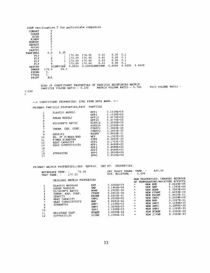
C.) Sample 3
A sample input and the relevant portions of the resulting output are shown below.This analysis is similar to Sample 1, except that the use and cure temperatures areset to 170 degrees F instead of 70 degrees F. The purpose of this change is toillustrate the degradation in binder properties that takes place due to elevatedtemperature. The effects of the degradation of the binder due to temperature result indegradation of the overall particulate reinforced matrix properties, as can be seen bycomparing the "COMP" computed properties in this example to those shown inSample 1. The effects of the binder property degradation can also be seen in theparticulate matrix microstresses. For example, the binder stress in the 1-1 direction islower for this case than in Sample 1, while the particle stress in the 1-1 direction is
higher in this case. This change in the stress state results from the binder having alower stiffness than in the previous case due to the degradation due to temperature.
32
ICAN verification 5 for particulate composite
COMSAT
CSANB
BIDE
RINDV
NONUDF
DEFECT
MICRO
PARTIC
PARFIMHS
PLY
PLY
PLY
PLY
MATCRD
PMEMB
PBEND
PTRAN
T
F
F
F
T
F
T
T
0.3 0.05
i i
2 1
3 1
4 1
ICOMFCOMP
170.4 00.0
0.
0.
ALL
170.00 170.00 0.00 0.00 0.I
170.00 170.00 0.00 0.00 0.i
170.00 170.00 0.00 0.00 0.I
170.00 170.00 0.00 0.00 0.I
0.0050 0.0000COMFCOMP 0.0000 0.0000 0.0000
0.050
I
ECHO OF CONSTITUENT PROPERTIES OF PARTICLE REINFORCED MATRIX
PARTICLE VOLUME RATIO - 0.300 MATRIX VOLUME RATIO - 0.700
--> CONSTITUENT PROPERTIES: ECHO FROM DATA BANK. <--
PRIMARY PARTICLE PROPERTIES;PARF PARTICLE
1 ELASTIC MODULI EFPI 0.1000E+06
2 EFP2 0.1000E+06
3 SHEAR MODULI GFPI2 0.4170E+05
4 GFP23 0.4170E+05
5 POISSON"S RATIO NUFPI2 0.2000E+00
6 NUFP23 0.2000E+00
7 THERM. EXP. COEF. CTEFPI 0.3600E-05
8 CTEFP2 0.3600E-05
9 DENSITY RHOFP 0.8830E-01
i0 NO. OF FIBERS/END NFP 0.1000E+05
Ii FIBER DIAMETER DIFP 0.3000E-03
12 HEAT CAPACITY CFPC 0.1700E+00
13 HEAT CONDUCTIVITY KFPI 0.8680E+00
14 KFP2 0.8680E+00
15 KFP3 0.8680E+00
16 STRENGTHS SFPT 0.2800E+06
17 SFPC 0.2000E+06
VOID VOLUME RATIO -
PRIMARY MATRIX PROPERTIES;IMHS MATRIX.
REFERENCE TEMP. - 70.00
TEST TEMP. - 170.00
ORIGINAL MATRIX PROPERTIES
1 ELASTIC MODULUS EMP
2 SHEAR MODULUS GMP
3 POISSON"S RATIO NUMP
4 THERM. EXP. COEF. CTEMP
5 DENSITY RHOMP
6 HEAT CAPACITY CMPC
7 HEAT CONDUCTIVITY KMP
8 STRENGTHS SMPT
9 SMPC
I0 SMPS
Ii MOISTURE COEF BTAMP
12 DIFFUSIVITY DIFMP
DRY RT. PROPERTIES.
DRY GLASS TRANS. TEMP. -
PCT. MOISTURE - 0.000
420.00
NEW PROPERTIES: CHANGED BECAUSE
OF TEMPERATURE/MOISTURE EFFECTS
0.5000E+06 *
0.1852E+06 *
0.3500E+00 *
0.3600E-04 *
0.4400E-01 *
0.2500E+00 *
0.8681E-02 *
0.1500E+05 *
0.3500E+05 *
0.1300E+05 *
0.4000E-02 *
0.2000E-03 *
NEW EMP
NEW GMP
NEW NUMP
NEW CTEMP
NEW RHOMP
NEW CMPC
NEW KMP
NEW SMPT
NEW SMPC
NEW SMPS
NEW BTAMP
NEW DIFMP
0.4226E+06
0.1565E+06
0.3500E+00
0 4260E-04
0 4400E-01
0 2958E+00
0 1027E-01
0 1268E+05
0 2958E+05
0 1099E+05
0 4000E-02
0.2000E-03
33
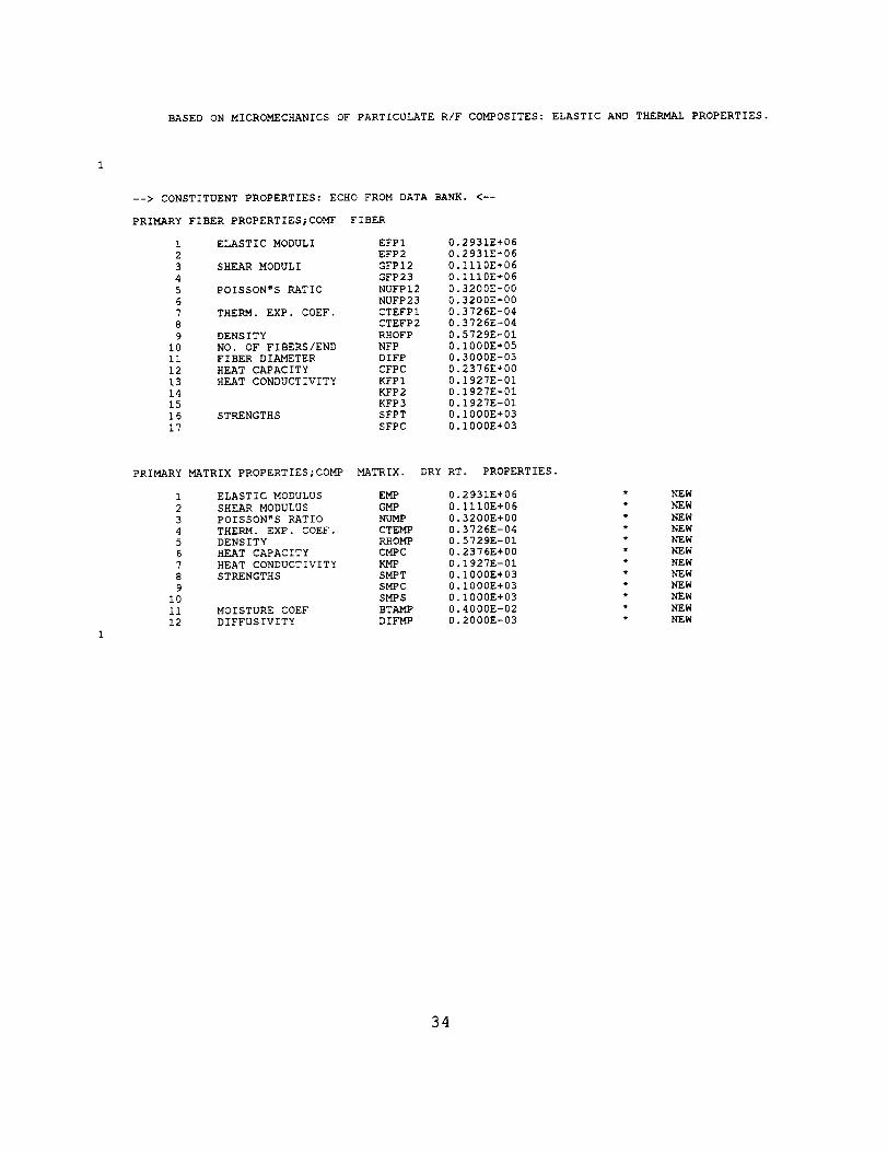
BASED ON MICROMECHANICS OF PARTICULATE R/F COMPOSITES: ELASTIC AND THERMAL PROPERTIES.
--> CONSTITUENT PROPERTIES: ECHO FROM DATA BANK. <--
PRIMARY FIBER PROPERTIES;COMF FIBER
1 ELASTIC MODULI EFPI 0.2931E+06
2 EFP2 0.2931E+06
3 SHEAR MODULI GFPI2 0.1110E+06
4 GFP23 0.1110E+06
5 POISSON"S RATIO NUFPI2 0.3200E+00
6 NUFP23 0.3200E+00
7 THERM. EXP. COEF. CTEFPI 0.3726E-04
8 CTEFP2 0.3726E-04
9 DENSITY RHOFP 0.5729E-01
10 NO. OF FIBERS/END NFP 0.1000E+05
ii FIBER DIAMETER DIFP 0.3000E-03
12 HEAT CAPACITY CFPC 0.2376E+00
13 HEAT CONDUCTIVITY KFPI 0.1927E-01
14 KFP2 0.1927E-01
15 KFP3 0.1927E-01
16 STRENGTHS SFPT 0.1000E+03
17 SFPC 0.1000E+03
PRIMARY MATRIX PROPERTIES;COMP MATRIX. DRY RT. PROPERTIES.
1 ELASTIC MODULUS EMP 0.2931E+06
2 SHEAR MODULUS GMP 0.1110E+06
3 POISSON"S RATIO NUMP 0.3200E+00
4 THERM. EXP. COEF. CTEMP 0.3726E-04
5 DENSITY RHOMP 0.5729E-01
6 H_T CAPACITY CMPC 0.2376E+00
7 HEAT CONDUCTIVITY KMP 0.1927E-01
8 STRENGTHS SMPT 0.1000E+03
9 SMPC 0.1000E+03
I0 SMPS 0.1000E+03
ii MOISTURE COEF BTA!MP 0.4000E-02
12 DIFFUSIVITY DIFMP 0.2000E-03
NEW
NEW
NEW
NEW
NEW
NEW
NEW
NEW
NEW
NEW
NEW
NEW
34

PRIMARY COMPOSITE PROPERTIES;COMF/COMP
BASED ON MICROMECHANICS OF INTRAPLY HYBRID COMPOSITES: ELASTIC AND THERMAL PROPERTIES.
0.000
FIBER VOLUME RATIO - 0.005
1 ELASTIC MODULI
2
3
4 SHEAR MODULI
5
6
7 POISSON"S RATIO
8
9
i0 THERM. EXP. COEF.
ii
12
13 DENSITY
14 HEAT CAPACITY
15 HEAT CONDUCTIVITY
16
17
18 STRENGTHS
19
2O
21
22
23 MOIST. DIFFUSIVITY
24
25
26 MOIST. EXP. COEF.
27
28
29 FLEXURAL MODULI
3O
31 STRENGTHS
32
33
34
35 PLY THICKNESS
36 INTERPLY THICKNESS
37 INTERFIBER SPACING
MATRIX VOLUME RATIO - 0.995
EPCI
EPC2
EPC3
GPCI2
GPC23
GPCI3
NUPC12
NUPC23
NUPCI3
CTEPCI
CTEPC2
CTEPC3
RHOPC
CPC
KPCI
KPC2
KPC3
SPCIT
SPCIC
SPC2T
SPC2C
SPCI2
DPCI
DPC2
DPC3
BTAPCI
BTAPC2
BTAPC3
EPCIF
EPC2F
SPC23
SPCIF
SPC2F
SPCSB
TPC
PLPC
PLPCS
0.2931E+06
0.2931E+06
0.2931E+06
0.1110E+06
0.II10E+06
0.1110E+06
0.3200E+00
0.3200E+00
0.3200E+00
0.3726E-04
0.3726E-04
0.3726E-04
0.5729E-01
0.2376E+00
0.1927E-01
0.1927E-01
0.1927E-01
O.5000E+O0
0.5000E+00
0.1000E+03
0.10GOE+03
0.I000E+03
0.1990E-03
0.1859E-03
0.1859E-03
0.3980E-02
0.3723E-02
0.3723E-02
0.2931E+06
0 2931E+06
0 I000E+03
0 6250E+00
0 1250E+03
0 1500E+03
0 5000E-02
0 3460E-02
0 3460E-02
VOID VOLUME RATIO -
35
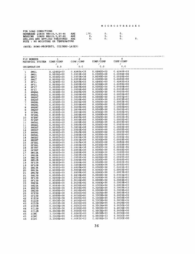
M I CROS TRE S S E S
FOR LOAD CONDITIONS
M2_/MBRANE LOADS NBS (X, Y, XY-M) ARE 170. 0. 0.
BENDING LOADS MBS (X, Y, XY-M) ARE 0. 0. 0.
QXZ,QYZ AND APPLIED PRESSURES ARE 0. 0. 0.
NOTE : NO MOISTURE OR TEMPERATURE
(NOTE: ROWS-PROPERTY, COLUMNS-LAYER)
0.
PLY NUMBER 1 2 3 4
MATERIAL SYSTEM COMF/COMP COMF/COMP COMF/COMP COMF / COMP
I / / /
ORIENTATION 0.0 0.0 0.0 0.0
...........................................................................................
1 SMIL 0.4260E+03 0.4260E+03 0.4260E+03 0.4260E+03
1 SMIL 0.0000E+00
2 SMIT 0.0000E+00
2 SMIT 0.0000E+00
3 SFIL 0.4260E+03
3 SFIL 0.0000E+00
4 SFIT 0.0000E+00
4 SFIT 0.0000E+00
5 SM2AL 0.0000E+00
5 SM2AL 0.0000E+00
6 SM2AT 0.0000E+00
6 SM2AT 0.0000E+00
7 SM2BL 0.0000E+00
7 SM2BL 0.0000E+00
8 SM2BT 0.0000E+00
8 SM2BT 0.0000E+00
9 SF2BL 0.0000E+00
9 SF2BL 0.0000E+00
i0 SF2BT 0.0000E+00
i0 SF2BT 0.0000E+00
ii SM3AL 0.0000E+00
ii SM3AL 0.0000E+00
12 SM3AT 0.0000E+00
12 SM3AT 0.0000E+00
13 SM3BL 0.0000E+00
13 SM3BL 0.0000E+00
14 SM3BT 0.0000E+00
14 SM3BT 0.0000E+00
15 SF3BL 0.0000E+00
15 SF3BL 0.0000E+00
16 SF3BT 0.0000E+00
16 SF3BT 0.0000E+00
17 SMI2A 0.0000E+00
17 SMI2A 0.0000E+00
18 SM12B 0.0000E+00
18 SMI2B 0.0000E+00
19 SF12B 0.0000E+00
19 SF12B 0.0000E+00
20 SMI3A 0.0000E+00
20 SMI3A 0.0000E+00
21 SMI3B 0.0000E+00
21 SMI3B 0.0000E+00
22 SFI3B 0.0000E+00
22 SFI3B 0.0000E+00
23 SM23A 0.0000E+00
23 SM23A 0.0000E+00
24 SM23B 0.0000E+00
24 SM23B 0.0000E+00
25 SF23B 0.0000E+00
25 SF23B 0.0000E+00
42 SI22B 0.0000E+00
42 SI22B 0.0000E+00
43 SI33B 0.0000E+00
43 SI33B 0.0000E+00
44 SII2B 0.0000E+00
44 SIl2B 0.0000E+00
45 SINC 0.0000E+00
45 SINC 0.0000E+00
46 SISC 0.0000E+00
0.0000E+00
0.0000E+00
0.0000E+00
0.4260E+03
0.0000E+00
0.0000E+00
0.0000E+00
0.0000E+00
0.0000E+00
0.0000E+00
0.0000E+00
0.0000E+00
0.0000E+00
0.0000E+00
0.0000E+00
0.0000E+00
0.0000E+00
0.0000E+00
0.0000E+00
O.O000E+O0
0.0000E+00
0.0000E+00
0.0000E+00
0.0000E+00
0.0000E+00
0.0000E+00
0.0000E+00
0.0000E+00
0.0000E+00
0.0000E+00
0.0000E+00
0.0000E+00
0.0000E+00
0.0000E+00
0.0000E+00
0.0000E+00
0.0000E+00
0.0000E+00
0.0000E+00
C.O000E+O0
0.0000E+00
0.0000E+00
0.0000E+00
0.0000E+00
0.0000E+00
0.0000E+00
0.0000E+00
0.0000E+00
0.0000E+00
0.0000E+00
0 0000E+00
0 0000E+00
0 0000E+00
0 0000E+00
0 0000E+00
0 0000E+00
0 0000E+00
0 0000E+00
0.0000E+00 0.0000E+00
0.0000E+00 0.0000E+00
0.0000E+00 0.0000E+00
0.4260E+03 0.4260E+03
0.0000E+00 0.0000E+00
0.0000E+00 0.0000E+00
0.0000E+00 0.0000E+00
0.0000E+00 0.0000E+00
0.0000E+00 0.0000E+00
0.0000E+00 0.0000E+00
0.0000E+00 0.0000E+00
0.0000E+00 0.0000E+00
0.0000E+00 0.0000E+00
0.0000E+00 0.0000E+00
0.0000E+00 0.0000E+00
0.0000E+00 0.0000E+00
0.0000E+00 0.0000E+00
0.0000E+00 0.0000E+00
0.0000E+00 0.0000E+00
0.0000E+00 0.0000E+00
0.0000E+00 0.0000E+00
0.0000E+00 0.0000E+00
0.0000E+00 0.0000E+00
0.0000E+00 0.0000E+00
0.0000E+00 0.0000E+00
0.0000E+00 0.0000E+00
0.0000E+00 0.0000E+00
0.0000E+00 0.0000E+00
0.0000E+00 0.0000E+00
0.0000E+00 0.0000E+00
0.0000E+00 0.0000E+00
0.0000E+00 0.0000E+00
0.0000E+00 0.0000E+00
O.0000E+00 0.0000E+00
0.0000E+00 0.0000E+00
0.0000E+00 0.0000E+00
0.0000E+00 0.0000E+00
0.0000E+00 0.0000E+00
0.0000E+00 0.0000E+00
0.0000E+00 0.000DE+00
0.0000E+00 0.000DE+00
0.0000E+00 0.0000E+00
0.0000E+00 0.0000E+00
0.0000E+00 0.0000E+00
0.0000E+00 0.0000E+00
0.0000E+00 0.0000E+00
0.0000E+00 0.0000E+00
0.0000E+00 0.0000E+00
0.O000E+00 0.0000E+00
0.O000E+00 0.0000E+00
0.0000E+00 0.0000E+00
0.0000E+00 0.0000E+00
0.0000E+00 0.0000E+00
0.0000E+00 0.0000E+00
0.0000E+00 0.0000E+00
0.0000E+00 0.0000E+00
0.0000E+00 0.0000E+00
0.0000E+00 0.0000E+00
36

46 SISC 0.0000E+00 0.0000E+00 0.0000E+00 0.0000E+00
...........................................................................................
NOTATION: S --- STRESS (SIGMA)
M --- MATRIX , F --- FIBER AND I --- INTERFACE
1,2,3 --- DIRECTIONS FOR STRESSES - PLY MATERIAL AXES
L,T --- DIRECTIONS OF PLY STRESSES
A --- REGION CONTAINING NO FIBERS
B --- REGION CONTAINING FIBERS AND MATRIX
EXAMPLE: SM2AL STANDS FOR TRANSVERSE NORMAL STRESS
IN REGION A DUE TO A LOAD IN THE LONGITUDINAL
DIRECTION
37
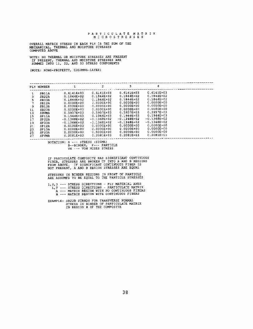
PARTICULATE MATRIX
MICROSTRES SES
OVERALL MATRIX STRESS IN EACH PLY IS THE SUM OF THE
MECHANICAL, THERMAL AND MOISTURE STRESSES
COMPUTED ABOVE
NOTE: NO THERMAL OR MOISTURE STRESSES ARE PRESENT
IF PRESENT, THERMAL AND MOISTURE STRESSES ARE
SUMMED INTO ii, 22, AND 33 STRESS COMPONENTS
(NOTE: ROWS-PROPERTY, COLUMNS-LAYER)
1 SBIIA 0.6141E+03 0.6141E+03 0.6141E+03 0.6141E+03
3 SB22A 0.1844E+02 0.1844E+02 0.1844E+02 0.1844E+02
5 SB33A 0.1844E+02 0.1844E+02 0.1844E+02 0.1844E+02
7 SBI2A 0.0000E+00 0.0000E+00 0.0000E+00 0.0000E+00
9 SBI3A 0.0000E+00 0.0000E+00 0.0000E+00 0.0000E+00
II SB23A 0.0000E+00 0.0000E+00 0.0000E+00 0.0000E+00
13 SBVMA 0.5957E+03 0.5957E+03 0.5957E+03 0.5957E+03
15 SPIIA 0.1944E+03 0.1944E+03 0.1944E+03 0.1944E+03
17 SP22A -0.1368E+02 -0.1368E+02 -0.1368E+02 -0.1368E+02
19 SP33A -0.1368E+02 -0.1368E+02 -0.1368E+02 -0.1368E+02
21 SPI2A 0.0000E+00 0.0000E+00 0.0000E+00 0.0000E+00
23 SPI3A 0.0000E+00 0.0000E+00 0.0000E+00 0.0000E+00
25 SP23A 0.0000E+00 0.0000E+00 0.0000E+00 0.0000E+00
27 SPVMA 0.2081E+03 0.2081E+03 0.2081E+03 0.2081E+03
NOTATION: S --- STRESS (SIGMA)
B--BINDER, P--- PARTICLE
VM --- VON MISES STRESS
IF PARTICULATE COMPOSITE HAS SIGNIFICANT CONTINUOUS
FIBER, STRESSES ARE BROKEN UP INTO A AND B'REGIONS
FROM ABOVE. IF SIGNIFICANT CONTINUOUS FIBER IS
NOT PRESENT, A AND B REGION STRESSES ARE EQUAL
STRESSES IN BINDER REGIONS IN FRONT OF PARTICLE
ARE ASSUMED TO BE EQUAL TO THE PARTICLE STRESSES
1,2,3 --- STRESS DIRECTIONS - PLY MATERIAL AXES
L,T --- STRESS DIRECTIONS - PARTICULATE MATRIX
A --- MATRIX REGION WITH NO CONTINUOUS FIBERS
B --- MATRIX REGION WITH CONTINUOUS FIBERS
EXAMPLE: SB22B STANDS FOR TRANSVERSE NORMAL
STRESS IN BINDER OF PARTICULATE MATRIX
IN REGION B OF THE COMPOSITE
38

Material Databank
The constituent material properties are stored in a material databank in the sameformat and manner as in the ICAN code [2]. The only difference is that the particles
are assumed to be isotropic, and thus equal values are put into the databank for the
properties in each of the component directions. The following particle properties areprovided in the databank under the fiber properties subsection in the format shownbelow:
PARF FILLER PARTICLES E=I/5E of IMHS.
$$$Number of fibers per end Nf 10000 number
Filament equivalent diameter df 0.300E-03 inches
Weight density Rhof 0.883E-01 ib/in**3Normal moduli (II) Efll 1.000E+05 psi
Normal moduli (22) Ef22 1.000E+05 psi
Poisson"s ratio (12) Nufl2 0.200E+00 non-dim
Poisson"s ratio (23) Nuf23 0.200E+00 non-dim
Shear moduli (12) Gfl2 0.417E+05 psiShear moduli (23) Gf23 0.417E+05 psi
Thermal expansion coef. (ii) Alfafll 3.600E-06 in/in/F
Thermal expansion coef. (22) Alfaf22 0.360E-05 in/in/FHeat conductivity (ii) Kfll 0.868E+00 BTU-in/hr/in**2/F
Heat conductivity (22) Kf22 0.868E+00 BTU-in/hr/in**2/F
Heat capacity Cf 0.170E+00 BTU/Ib/FFiber tensile strength SfT 0.280E+06 psi
Fiber compressive strength SfC 0.200E+06 psi
PAR1 SAMPLE FILLER PARTICLE 1
$$$Number of fibers per end Nf 10000 number
Filament equivalent diameter df 0.300E-03 inches
Weight density Khof 0.883E-01 ib/in**3Normal moduli (ii) Efll 2.000E+07 psi
Normal moduli (22) Ef22 2.000E+07 psi
Poisson"s ratio (12) Null2 0.250E+00 non-dimPoisson"s ratio (23) Nuf23 0.250E+00 non-dim
Shear moduli (12) Gfl2 8.000E+06 psi
Shear moduli (23) Gf23 8.000E+06 psi
Thermal expansion coef. (ii) Alfafll 4.000E-06 in/in/F
Thermal expansion coef. (22) Alfaf22 4.000E-06 in/in/FHeat conductivity (ii) Kfll 0.868E+00 BTU-in/hr/in**2/F
Heat conductivity (22) Kf22 0.868E+00 BTU-in/hr/in**2/F
Heat capacity Cf 0.170E+00 BTU/lb/FFiber tensile strength SfT 0.280E+06 psi
Fiber compressive strength SfC 0.200E+06 psi
39
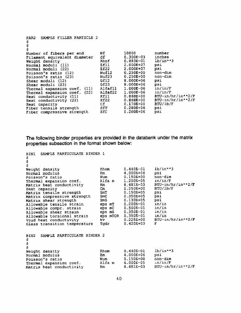
PAR2 SAMPLE FILLER PARTICLE 2
$$$Number of fibers per end Nf 10000 number
Filament equivalent diameter df 0.300E-03 inches
Weight density Khof 0.883E-01 ib/in**3Normal moduli (ii) Efll 2.000E+07 psiNormal moduli (22) Ef22 2.000E+07 psi
Poisson"s ratio (12) Nufl2 0.250E+00 non-dim
Poisson"s ratio (23) Nuf23 0.250E+00 non-dim
Shear moduli (12) Gfl2 8.000E+06 psi
Shear moduli (23) Gf23 8.000E+06 psi
Thermal expansion coef. (II) Alfafll 1.000E-06 in/in/F
Thermal expansion coef. (22) Alfaf22 1.000E-06 in/in/FHeat conductivity (Ii) Kfll 0.868E+00 BTU-in/hr/in**2/F
Heat conductivity (22) Kf22 0.868E+00 BTU-in/hr/in**2/F
Heat capacity Cf 0.170E+00 BTU/Ib/F
Fiber tensile strength SfT 0.280E+06 psi
Fiber compressive strength SfC 0.200E+06 psi
The following binder properties are provided in the databank under the matrix
properties subsection in the format shown below:
SAMPLE PARTICULATE BINDER iBIN1
$$$Weight density RhomNormal modulus Em
Poisson"s ratio Num
Thermal expansion coef. Alfa mMatrix heat conductivity Km
Heat capacity Cm
Matrix tensile strength SmT
Matrix compressive strength SmCMatrix shear strength SmS
Allowable tensile strain eps mT
Allowable compr, strain eps mC
Allowable shear strain eps mS
Allowable torsional strain eps mTOR
Void heat conductivity kv
Glass transition temperature Tgdr
0.440E-01 Ib/in**3
4.000E+06 psi0.150E+00 non-dim
1.200E-05 in/in/F8.681E-03 BTU-in/hr/in**2/F
0.250E+00 BTU/Ib/F
0.150E+05 psi
0.350E+05 psi
0.130E+05 psi0.200E-01 in/in
0.500E-01 in/in
0.350E-01 in/in
0.350E-01 in/in
0.225E+00 BTU-in/hr/in**2/F
0.420E+03 F
BIN2
$$$Weight densityNormal modulus
Poisson"s ratio
Thermal expansion coef.
Matrix heat conductivity
SAMPLE PARTICULATE BINDER 2
Rhom 0.440E-01 ib/in**3
Em 4.000E+06 psiNum 0.150E+00 non-dim
Alfa m 4.000E-05 ±n/in/F
Km 8.681E-03 BTU-in/hr/in**2/F
4O

Heat capacity Cm
Matrix tensile strength SmT
Matrix compressive strength SmC
Matrix shear strength SmSAllowable tensile strain eps mT 0
Allowable compr, strain eps mC 0Allowable shear strain eps mS 0
Allowable torsional strain eps mTOR 0
Void heat conductivity kv 0
Glass transition temperature Tgdr 0
0.250E+00 BTU/Ib/F
0.150E+05 psi
0.350E+05 psi
0.130E+05 psi.200E-01 in/in
.500E-01 in/in
.350E-01 in/in
.350E-01 in/in
.225E+00 BTU-in/hr/in**2/F
.420E+03 F
In addition to the particles and binders listed above, all of the fiber and matrix
properties that are present in the default databank of the original ICAN are present inICAN/PART. Additionally, the user can add any materials desired to the databank by
adding a dataset, using the appropriate format, to the appropriate area of the
databank (fiber subsection for fibers or particles, matrix subsection for matrices or
binders). As in the original ICAN, the properties in the material databank are
accessed by specifying the appropriate four letter code names in the input deck. Asmentioned in an earlier section, the material databank must be given the UNIX filename "databk.dat" and be located in the same directory as the executable of the
ICAN/PART code.
41
VERIFICATION OF ICAN/PART CODE
Due to the approximate nature of the micromechanics equations programmed intoICAN/PART [1], a quantitative verification of the computed results was conducted toensure that the micromechanics included in ICAN/PART model the mechanics of the
problem correctly. Specifically, three dimensional finite element and boundary elementanalyses of a representative volume element were performed. The particle was the"PAR1" particle from the material databank, and the binder was the "BIN1" binder. Aparticle volume fraction of 0.3 was utilized, and no continuous fibers were present inthe composite.
For the finite element analysis, the finite element code MSC/NASTRAN [4] wasutilized. The particulate composite was modeled by embedding a cube of dimensions1" X 1" X 1" (the particle) into another cube of dimensions 1.5" X 1.5" X 1.5". Acomposite with a particle volume fraction of 0.3 was thus modeled. Even though anactual particle would not necessarily have a cubed shape, this geometry was chosensince the micromechanics equations in ICAN/PART assume such a shape for the
representative volume element. By utilizing a cubed particle shape in the finiteelement analysis, full compatibility between the ICAN/PART micromechanics and thefinite element model is ensured. A cut-away view of the finite element model (with the
cutting plane at halfway through the thickness) is shown in Figure 3. This cut-awayview shows how the particle is embedded in the binder. Eight noded brick elementswere used for the finite element mesh. The particle was meshed with 64 elements,and the total number of elements for the composite was 1000. The model is
subjected to both mechanical and thermal loads. The boundary conditions imposedfor the mechanical loads case include an enforced uniform displacement on one sideof the model (X=1.5"), while the other side (X=0") is fixed in all three coordinate
directions. The resulting nodal forces are then obtained from the finite elementanalysis, which are then summed and averaged on the face where the enforceddisplacements were imposed. For this particular analysis, the average nodal forceturned out to be 426 psi. The average nodal force is then divided by the cross-sectional area to obtain the average stress resulting from the applied uniform strain.The equivalent modulus of the composite can then be calculated from this information.To compute the equivalent thermal expansion coefficient, a uniform temperatureincrease of 100 deg. F was applied to the model, and the resulting averagedisplacement on a cross section of interest was determined. From this information,the average strain due to thermal loading on the cross-section was determined, andthe thermal expansion coefficient for the composite was then calculated.
For the boundary element analysis, the NASA Lewis developed boundary elementanalysis code BEST-CMS [5] was utilized to analyze the composite. The geometryand dimensions for the boundary element model are identical to what was used for thefinite element model. A cut-away view of the boundary element mesh is shown in
42
Figure 4, in which portions of the binder mesh were cut away in order to display theparticle. In discretizing the model, the major difference between the boundary elementmethod and the more commonly utilized finite element method is that while for thefinite element method the entire volume of a domain is discretized using volume
elements, with the boundary element method only the outer surface of the domain isdiscretized using surface elements. For this analysis, 54 eight noded quadrilateralsurface elements were used to mesh the particulate, and the total number of elements
for the composite was 162. An important point to note is that only the outer surface ofthe cube representing the particulate and the cube representing the surrounding matrixare discretized. Another important point to note is that with the boundary elementmethodology acceptable results can be obtained using a much coarser mesh than is
required for an equivalent finite element model.
To compute the average modulus using BEM, an applied traction (pressure) loadequal to the average nodal load determined in the finite element analysis was appliedto one face (Z=1.5") of the composite, while roller constraints were applied to the X=0,Y=0 and Z=0 faces. The average nodal displacement (and thus the average strain),
was then computed on the face on which the traction load was applied. The effectivemodulus was computed using the applied traction load and the resulting average nodalstrain. The effective thermal expansion coefficient was computed by applying a
uniform temperature increase of 100 deg. F to the model, and then computing theaverage nodal displacement (and thus strain) on the Z=1.5" face of the model. Themanner in which the effective properties were computed for the boundary elementmodel differs somewhat from that utilized for the finite element model since the currentversion of the boundary element analysis software does not permit multi-pointconstraint boundary conditions. Additionally, the most accurate results are computedon the outer surfaces of the boundary element model.
As part of the finite element analyses, microstresses were also computed in theconstituents of the particulate matrix composite in order to allow a comparison to thevalues computed in ICAN/PART. In general, the three dimensional stresses computedby a finite element analysis vary significantly throughout the model. In order toconsistently compare these values to the values computed by ICAN/PART, which arethe "average" stresses in each constituent, the stresses computed by the finiteelement method must be averaged in various regions in each constituent of the
composite. Stress calculations for the interior of the model were not available for theboundary element model due to current limitations in the boundary element analysissoftware which do not allow detailed calculations of stress states in the interior of the
model.
The equivalent composite properties computed utilizing the various analysismethods are presented in the table below.
43

Property Boundary Element ICAN/PART Finite Element
Modulus, Msi 5.9 6.1 6.4
Poisson's Ratio .179 .17 .164
Shear Modulus, -...... 2.6 2.74
Msi
Coeff. of Thermal 8.5 8.6 8.94
Exp. E-06 in/in/F
The effective properties computed by ICAN/PART compare favorably to both the finiteelement and boundary element results. Additionally, the ICAN/PART results fall withinbounds established by the boundary element and finite element results. These resultsindicate that ICAN/PART is adequately modeling the mechanics and computing the
equivalent properties with acceptable accuracy. Additionally, ICAN/PART cancompute these values in a fraction of the time required to conduct detailed finiteelement or boundary element analyses.
The stresses in the particle and the binder due to both mechanical and thermal
loading are shown in the table below. The mechanical and thermal loads were appliedseparately, in separate analyses. The mechanical load was an axial load of 426 psi,which is identical to the load utilized in computing the effective properties. Thethermal load was a uniform temperature increase of 100 deg. F. Results computed
using both ICAN/PART and the finite element method are included. It is important tonote that the stresses listed for the finite element results are the average stresses
over the constituent, and that the actual stress state varies over the constituent. Theloading levels are identical to those discussed above in the micromechanics
predictions section.
Stress (psi) ICAN/PART Finite Element
Particle: Mechanical Load 604.7 580
Binder: Mechanical Load 280.9 265
Particle: Thermal Load 2075 1000-3000
Binder: Thermal Load 1412 1600
The stress results computed by ICAN/PART compare fairly well to the results
computed by the finite element method, with the results due to mechanical loadingfalling within 7% of each other. In ICAN/PART, due to the approximations involved in
44

deriving the microstress equations the computed results are only average values overthe constituent, while in reality the stress state varies considerably over the entire
range of the representative volume element. Additionally, continuity in stress states isnot imposed between the various regions of the unit cell. For the finite elementmodel, modeling the particulate as a cube may have introduced stress concentrationsat the corners that may not be present in the actual material (and are not accountedfor in the ICAN/PART derivations). Overall, if an analyst is interested in obtaining
preliminary information on the order of magnitude of stresses that will be found in aparticulate composite due to a given load state, ICAN/PART appears to givereasonable answers. If a user is interested in more detailed information about the
specific stress levels in specific locations of the composite, a detailed finite elementmodel could then be constructed and analyzed.
CONCLUSIONS
The ICAN/PART computer code has been developed in order to predict the
effective properties and constituent microstresses for particulate reinforcedcomposites. ICAN/PART is based and derived from the ICAN computer code, whichwas developed in order to conduct micromechanical analyses of fiber reinforced
polymer matrix composites. Details of the input and output, along with examples,have been presented. Effective properties computed using ICAN/PART were found tocompare favorably to results computed using detailed three dimensional finite elementand boundary element analyses. Microstresses computed using ICAN/PART
compared favorably in an average sense with results computed using finite elementanalyses. These results indicate that the micromechanics equations programmed intoICAN/PART model the mechanics of the problem correctly. However, themicrostresses computed by ICAN/PART should be seen only as preliminary, averagedresults.
Immediate goals for future work will involve adding to ICAN/PART the capability toaccount for the effects of moisture on both the effective properties and themicrostresses. In addition, the capability to account for an interfacial region betweenthe fiber and the matrix will be included. Such interfacial regions have been found to
frequently exist in particulate reinforced composites, and can strongly effect theeffective properties, particularly the effective strength. Overall, capabilities to predictthe effective composite strength will be included. Longer term efforts may involveadding the capability to incorporate cyclic loading conditions. Additionally, longer termefforts may involve adding the capability to incorporate uncertainties in the material
properties through the use of probabilistic approaches.
45

|
REFERENCES
1. Mital, S.K.; Murthy, P.L.N.; and Goldberg, R.K.: Micromechanics for ParticulateReinforced Composites, NASA TM, To be published.
2. Murthy, P.L.N.; Ginty, C.A; and Sanfeliz, J.G.: Second Generation IntegratedComposite Analyzer (ICAN) Computer Code. NASA TP-3290, 1993.
3. Agarwal, B.D.; and Broutman, L.J.: Analysis and Performance of Fiber Composites,Second Edition. John Wiley and Sons, Inc., 1990.
4. MSC/NASTRAN, Version 68.2, Users Manual, The MacNeil Schwendler
Corporation, 1995.
5. Henry, D.P.; Banerjee, P.K.; and Dargush, G.F.: Development of BoundaryElement Methods for Ceramic Composites. NASA Contractor Report 195326, NASALewis, 1994.
46

Rnlte eklment
Component
Finlte element
Il\
/
/Lamlrmte
ICAN
Compositemicromechanlcs Compo_te
theory mlcromectmnics /theory
\ \ 0 /
\\ ---- //Upward Coc_tlt uents
Material properties / Top-downIntegrated or _ P ( _, T.M) traced or
"_,n_- __ ._/ "_ecom_.Jtk_n"
II/
Figure 1: Flowchart showing the integrated analysis approach included in ICAN.
4q

":_ /
!oo_
Uhl I
I,IJJt3O
'0
-.4k4
0_ I
IO
L.o_l c
=1:1.'.1
OOu_I4
•FI Uk _kG) ll
I _u. I
O*
°_1 I_'-
, 1,l
:s
• 4-,4 -,441e _lO .I,.4.,4
_. _._ Uq_
k _
b
.,4
, m
_K
_0_
0
_ke m
- _._ ___0
i e "1
u_#.,,_
UM
Figure 2: Flowchart showing specifics of ICAN/PART execution.
48

/
"1I
I
I
t-
Particle
Binder
Figure 3: Cross-sectional view of 3-D FEM model of particulate composite unit cell.
J
Particle
Binder
Figure 4: Cut-away view of 3-D BEM model of particulate composite unit cell
49

Form ApprovedREPORT DOCUMENTATION PAGE OMBNo.0704-0188
Pul:dic r_Dorting borden toe this cu011K_on of I¢4ocmalion is estimated to av_._ 1..11__r I_. ,r.era., I_d_ng the time 10¢ r_i_l_ I_. tnx_ins, _ eocilzb_g _ sou K:_.,gathering anti maintaining the clara needed, and cOm.l_,., ng _ reviewing me cmmcmx_, ov ,morrnaCmn. _ c__,mments r_garoi.Rg m l$ o uf_(_M1epmge o¢ aJly o(h___al.l_l_. .. of tillsco_ilctlon Of Iofo_. inctuomg suggastioTw for reouclng ms borden, to Washington i-teaoquatters ._etvlces, UlreCtOrale rot intoml_on _ _ Hepcxt_ 1z1_ JenefuonDavis H_hway. Suite 1204. Arlington. VA 22202-43_., and to the Office of Management and B_ Paper, Nork Reduction Project (0704-0188), Washington. DC 20503.
1. AGENCY USE ONLY (Leave b/ank) 2. REPORT DATE 3. REPORT TYPE AND DATES COVERED
August 1996
4. TITLE AND SUBTrrLE
ICAN/PART: Particulate Composite Analyzer, User's Manual andVe"nfi_tion Studies
s. AUTHOR(S)
Robert K. Goldberg, Pappu L.N. Murthy, and Subodh K. Mital
7. PERFORMINGORGANIZATIONNAME{S)AND ADDRESS(ES)
National Aeronautics and Space AdministrationLewis Research Center
Cleveland, Ohio 44135-3191
9. SPONSORING/MONITORINGAGENCYNAME(S)ANDADDRESS(ES)
National Aeronautics and Space Administration
Washington, D.C. 20546-0001
Technical Memorandum
5. FUNDING NUMBERS
WU-243-30-0A
8. PERFORMING ORGANIZATION
REPORT NUMBER
E-10375
10. SPONSORING/MONITORING
AGENCY REPORT NUMBER
NASA TM- 107297
11. SUPPLEMENTARYNOTES
Robert K. Goldberg and Pappu L.N. Murthy, NASA Lewis Research Center; Subodh K. Mital, University of Toledo,Toledo, Ohio 43606. Responsible person, Robert K. Goldberg, organization code 5210, (216) 433-3330.
l_t. DISTI:UBUTION/AVAILABIUTYSTATEMENT
Unclassified - Unlimited
Subject Category 24
This publication is available from the NASA Center for AexoSpace Information, (301) 621-0390.
12b. DISTRIBUTION CODE
13. ABSTRACT (Maximum 200 words)
A methodology for predicting the equivalent properties and constituent microstresses for particulate matrix composites,
based on the micromechanics approach, is developed. These equations are integrated into a computer code developed topredict the equivalent properties and microstresses of fiber reinforced polymer matrix composites to form a new computercode, ICAN/PART. Demil_ of the flowchart, input and output for ICAN/PART are described, along with examples of the
input and outpuL Only the differences between ICAN/PART and the original ICAN code are described in detail, and theuser is assumed to be familiar with the slructure and usage of the original ICAN code. Detailed verification studies,utilizing three dimensional finite element and boundary element analyses, axe conducted in order to verify that the
micromechanics methodology accurately models the mechanics of particulate matrix composites. The equivalent proper-ties computed by ICAN/PART fall within bounds established by the finite element and boundary element results. Further-more, constituent microstresses computed by ICAN/PART agree in average sense with results computed using the finiteelement method. The verification studies indicate that the micromechanics programmed into ICAN/PART do indeed
accurately model the mechanics of particulate matrix composites.
14. SUBJECT TERMS
Composite materials; Particulate matrix composites; Finite element method;Boundary element method
17. SECURITY CLASSIFICATION 18. SECURITY CLASSIFICATION
OF REPORT OF THIS PAGE
Unclassified Unclassified
NSN 7540-01-280-5500
19. SECURITY CLASSIFICATION
OF ABSTRACT
Unclassified
15. NUMBER OF PAGES
5116. PRICE CODE
A0420. LIMITATION OF ABSTRACT
Standard Form 298 (Roy. 2-89)
Prescribed by ANSI Std. Z39-18298--102


_ o_=r" _z_'o !<o-. _"
_.___-" o_-= _-
_._-o- _e'J
0 .-L '_ O.0
z _00
:_0<0
3