icao iridium technical specification - 110105 working groups library/acp... · icao technical...
TRANSCRIPT

DRAFT
ICAO TECHNICAL SPECIFICATION FOR AERONAUTICAL MOBILE SATELLITE (ROUTE) SERVICE (AMS(R)S)
PROVIDED BY IRIDIUM SATELLITE SYSTEM
i
Table of Contents
1 IRIDIUM SYSTEM DEFINITIONS AND CAPABILITIES ................................................ 1 1.1 General ............................................................................................................................ 1 1.2 Applicable Documents.................................................................................................... 1 1.3 System and Constellation Architecture........................................................................... 1 1.4 System Capabilities......................................................................................................... 4 1.5 Support for AMS(R)S Requirements.............................................................................. 5 1.6 Operational Description .................................................................................................. 6 1.7 Pro-Forma Declaration of System Parameters................................................................ 7
2 BROADBAND RF CHARACTERISTICS.......................................................................... 10 2.1 Frequency Bands and Band Characteristics.................................................................. 10 2.2 Frequency Accuracy ..................................................................................................... 10 2.3 Aircraft Earth Station RF Characteristics ..................................................................... 10
2.3.1 Antenna Characteristics and Performance ............................................................ 10 2.3.2 Transmitter Requirements..................................................................................... 11 2.3.3 Receiver Requirements ......................................................................................... 12
3 RF CHANNEL CHARACTERISTICS ................................................................................ 16 3.1 Channel Multiplexing ................................................................................................... 16
3.1.1 TDMA Frame Structure........................................................................................ 16 3.1.2 FDMA Frequency Plan ......................................................................................... 16 3.1.3 Duplex Channel Band ........................................................................................... 17 3.1.4 Simplex Channel Band ......................................................................................... 18
3.2 L-Band Transmission Characteristics ........................................................................... 19 3.2.1 Downlink Channels............................................................................................... 20 3.2.2 Uplink Channels.................................................................................................... 20 3.2.3 Power Control ....................................................................................................... 20
3.3 Radiated Power Spectral Density.................................................................................. 21 3.3 Demodulator Performance ............................................................................................ 21 3.4 Acquisition Performance .............................................................................................. 21
4 CHANNEL FORMAT TYPES AND RATES ..................................................................... 22 4.1 General .......................................................................................................................... 22 4.2 Definitions and Descriptions of Channel Types ........................................................... 23 4.3 Traffic Channel for Iridium AMS(R)S ......................................................................... 24
5 CIRCUIT-MODE SERVICES ............................................................................................. 26 5.1 Circuit-mode General Requirements ............................................................................ 26 5.2 Circuit-mode Priority, Precedence and Preemption...................................................... 26 5.3 Circuit-mode Performance Requirements..................................................................... 26 5.4 Circuit-mode Voice Encoding Algorithm..................................................................... 26 5.5 Circuit-mode Procedures .............................................................................................. 26 5.6 Telephony Numbering Plan .......................................................................................... 27
6 SATELLITE SUBNETWORK LAYER DATA SERVICES .............................................. 28 6.1 General Provisions ........................................................................................................ 28 6.2 Packet-data System Architecture .................................................................................. 28 6.3 Packet-data Performance .............................................................................................. 30 6.4 Packet-data Priority, Precedence and Preemption ........................................................ 31

ii
6.5 Satellite Subnetwork-dependent Protocol Services and Operations............................. 31 6.5.1 Iridium RUDICS Service...................................................................................... 31
6.6 ISO-8208 Protocol Operations...................................................................................... 33 7 AIRCRAFT EARTH STATION (AES) MANAGEMENT ................................................. 34
7.1 AES Management Functions ........................................................................................ 34 7.2 AES Management Interfaces ........................................................................................ 34

1
1 IRIDIUM SYSTEM DEFINITIONS AND CAPABILITIES
1.1 General The Aeronautical Mobile-Satellite (R) Service, AMS(R)S, is designated by the ICAO and ITU for two-way communications via satellite(s) pertaining to the safety and regularity of flight along national or international civil air routes.
This document provides a description of the Iridium Communications Systems and the specific system characteristics that allow it to offer AMS(R)S.
Iridium is a commercially operated telephony and data communications systems designed by Motorola and operated by Iridium Satellite LLC. The system has been specifically modified to support AMS(R)S data and voice communications. The Iridium AMS(R)S offerings were approved as "broadly acceptable" by AMCP/6 in March 1999.
1.2 Applicable Documents Several relevant documents should be consulted in additional to this technical specification. The latest issue of the following documents shall form a part of this specification to the extent specified herein.
• Draft ICAO Core AMS(R)S SARPS for core specification of NGSS supporting AMS(R)S;
• RTCA DO-262, Minimum Operational Performance Standards for Avionics Supporting Next Generation Satellite Systems (NGSS), for minimum performance standard of NGSS AMS(R)S;
• RTCA DO-270, Minimum Aviation System Performance Standards (MASPS) for the Aeronautical Mobile-Satellite (R) Service (AMS(R)S) as Used in Aeronautical Data Links, for requirement and specification for the data link;
• RTCA DO-215A and RTCA DO-231 for guidance on overall data and voice performance requirements.
Copies of RTCA document may be obtained from RTCA, Inc., http://www.rtca.org. Copies of ICAO document may be obtained from ICAO, http://www.icao.int.
Detailed descriptions of some portions of the design and operation of Iridium AMS(R)S are contained in Iridium company documents and are referenced herein. These include the following:
• Iridium Air Interface Specification (AIS); • Iridium AT Commands Reference.
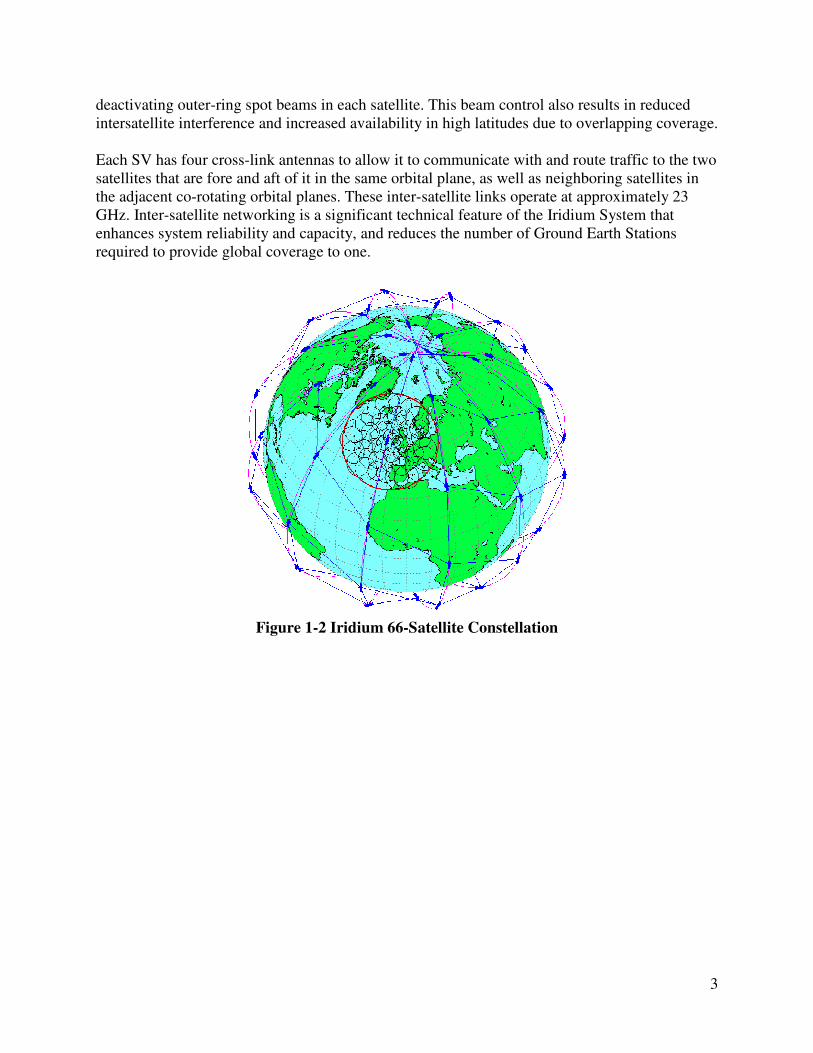
1.3 System and Constellation Architecture The Iridium System consists of satellites and related infrastructure, including the master and backup control facilities, the Gateways and associated tracking, telemetry and control facilities. The key elements of the Iridium System are illustrated in Figure 1-1. The Iridium space segment utilizes a constellation of 66 operational satellites in low-Earth orbit, as shown in Figure 1-2. The satellites are located in six distinct planes in near-polar orbit at an

2
altitude of approximately 780 kilometers and circle the Earth approximately once every 100 minutes. The six co-rotating planes are spaced 31.6o apart in longitude, resulting in a spacing between Plane 6 and the counter-rotating portion of Plane 1 of 22o. Satellites are evenly spaced within each plane. Satellite positions in adjacent odd and even numbered planes are offset from each other by one-half of the satellite spacing.
RF Cross LinkK-Band
23.18-23.38 GHz
GW Feeder LinksUp: 29.1-29.3 GHz Down: 19.4-19.6 GHz
48 Spot Beams per SV 4700 km total diameter
Space Vehicles (SV)780km
Iridium Gateway (GW)
AES
User TerrestrialGateway
AES
International Public Switched Telephone Network (I-PSTN)
ISU
Service Links L-Band 1616-1626.5 MHz
Control Feeder LinksUp: 29.1-29.3 GHz Down: 19.4-19.6 GHz
Iridium Telemetry, Tracking And Control (TTAC)
Service Links L-Band 1616-1626.5 MHz
RF Cross LinkK-Band
23.18-23.38 GHz
RF Cross LinkK-Band
23.18-23.38 GHz
GW Feeder LinksUp: 29.1-29.3 GHz Down: 19.4-19.6 GHz
GW Feeder LinksUp: 29.1-29.3 GHz Down: 19.4-19.6 GHz
48 Spot Beams per SV 4700 km total diameter
Space Vehicles (SV)780km
Iridium Gateway (GW)
AES
User TerrestrialGateway
AES
International Public Switched Telephone Network (I-PSTN)
International Public Switched Telephone Network (I-PSTN)
ISU
Service Links L-Band 1616-1626.5 MHz
Service Links L-Band 1616-1626.5 MHz
Control Feeder LinksUp: 29.1-29.3 GHz Down: 19.4-19.6 GHz
Control Feeder LinksUp: 29.1-29.3 GHz Down: 19.4-19.6 GHz
Iridium Telemetry, Tracking And Control (TTAC)
Service Links L-Band 1616-1626.5 MHz
Service Links L-Band 1616-1626.5 MHz
Figure 1-1 Key Elements of the Iridium Communication System
Each satellite communicates with subscriber units, including Aircraft Earth Stations (AESs) through tightly focused antenna beams that form a continuous pattern on the Earth’s surface. Each satellite uses three L-band phased-array antennas for the user links, each of which contains an array of transmit/receive modules. The phased-array antennas of each satellite create 48 spot beams arranged in the configuration shown in Figure 1-3 covering a circular area with a diameter of approximately 4,700 kilometers. These arrays are designed to provide user-link service by communicating within the 1616-1626.5 MHz band.
The Iridium system architecture incorporates certain characteristics, such as call hand-off, which allow the Space Segment communications link with subscriber equipment to be transferred from beam to beam and from satellite to satellite as such satellites move over the area where the subscriber is located. The near polar orbits of Iridium space vehicles (SVs) cause the satellites to get closer together as the sub-satellite latitude increases, as illustrated in Figure 1-2. This orbital motion, in turn, causes the coverage of neighboring SVs to increasingly overlap as the satellites approach the poles. A consistent sharing of load among satellites is maintained at high latitudes by selectively
3
deactivating outer-ring spot beams in each satellite. This beam control also results in reduced intersatellite interference and increased availability in high latitudes due to overlapping coverage. Each SV has four cross-link antennas to allow it to communicate with and route traffic to the two satellites that are fore and aft of it in the same orbital plane, as well as neighboring satellites in the adjacent co-rotating orbital planes. These inter-satellite links operate at approximately 23 GHz. Inter-satellite networking is a significant technical feature of the Iridium System that enhances system reliability and capacity, and reduces the number of Ground Earth Stations required to provide global coverage to one.
Figure 1-2 Iridium 66-Satellite Constellation

4
Figure 1-3 Iridium Spot-Beam Configuration
In Iridium terminology, the Ground Earth Station is referred to as a Gateway. Gateway stations provide call processing and control activities such as subscriber validation and access control for all calls placed in a Gateway territory. The Gateway station also provides interconnection between terrestrial Public Switched Telephone Networks (PSTNs) and the Iridium System by connecting calls made through the Iridium System to and from the PSTNs. Gateway communicates with the space segment via Gateway link antennas on the satellites and ground-based antennas at each terrestrial Gateway facility. Each Gateway includes a subscriber database used in call processing activities such as subscriber validation. Each Gateway also keeps a record of all traffic in its territory and generates call detail records used in billing.
1.4 System Capabilities The Iridium AMS(R)S shall support packet data service, or voice service, or both. Iridium provides AMS(R)S service using standard Iridium telephony and data protocols. AMS(R)S coverage extends over 100% of the Earth surface using AES equipment specially equipped and provisioned for AMS(R)S operation. Non-safety AMSS service is also provided throughout the coverage area. The primary AMS(R)S services include circuit-mode voice for cockpit crew and packet-data emulation. Packet data emulation results in an asynchronous packet data interface for both aeronautical and terrestrial users. Internally, Iridium provides the user packet data interface using Iridium-specific circuit-mode data protocols. It is envisioned that an AES incorporating two Iridium Subscriber Units (ISUs) connected to a dual-channel antenna to support two circuit-switched channels for circuit-switched voice or circuit-switched data services. A single circuit-switched data channel with nominal throughput of 2.4 kbps can be used to support multiple packet data channels.

5
1.5 Support for AMS(R)S Requirements Aeronautical communication services are described by four major categories:
• Air Traffic Services (ATS) - which includes air traffic control, and weather information provided by civil aviation administrations; e.g., the FAA;
• Aeronautical Operational Control (AOC) - primarily communications from an airline's operational control center that affect the safety and regularity of flight;
• Aeronautical Administrative Communications (AAC) - for example ticketing, special orders, passenger related information;
• Aeronautical Public Correspondence (APC) - personal communications by/for passengers.
ATS and AOC are considered safety services, while AAC and APC are considered non-safety services. Like existing AMSS services, Iridium plans to offer all categories using the same communications infrastructure, and, in fact, to share the infrastructure with non-aeronautical communications services. To assure that safety-related aeronautical services obtain timely access to the resources they need, the Iridium AMS(R)S includes provision for Priority, Precedence and Preemption (PPP) of system resources. The basis for Iridium AMS(R)S PPP is the set of mechanisms designed for, and already implemented in, the Iridium System for signaling and system management purposes. The Iridium System utilizes two resource management functions, Acquisition Class control and Priority Class control, to assure access to communication channels for priority users, and to protect the system from aberrant or fraudulent terminals. These operate in temporal sequence for each call through the system and are common for all users. The Acquisition process is one of several protocols completed between a terminal and the satellite constellation for each call set up in either direction. Its purpose is to assure that overall system resources, at a macro level, remain available optimally and fairly to AMS(R)S users. For example, traffic accepted may need to be restricted or ‘throttled’ in accordance with a predicted, impending overload of the system resources, or due to a local or regional emergency. Among the information exchanged between a terminal and its current serving satellite is the Acquisition Class. The highest-level Acquisition Class that can be assigned to a terminal (Class 14), is assigned to all aeronautical terminals that are approved for AMS(R)S. Thus, AMS(R)S terminals are the last terminals to be denied service in the event of a system-threatening event. The aeronautical terminals that are approved for AMS(R)S also support non-safety communications. All non-safety communications use an Acquisition Class in the range 0-9. The Acquisition Class affects how calls initially gain access to the satellite constellation while Priority Class provides continued access for safety-related calls.

6
Each satellite has mechanisms that determine the priority of queuing for in-progress calls to be handed off among beams or the succeeding serving satellite. AMS(R)S traffic receives priority over non-AMS(R)S traffic in the beam-to-beam and satellite-to-satellite handoff process. To allow the priority of a call to be maintained by the network for the duration of the call, during each inter-satellite handoff the priority code is included in the call overhead messaging between the satellites. The high priority calls are queued for handoff before those calls of lower priority. Within the AMS(R)S Acquisition Class (number 14), four levels of priority are defined:
Iridium Priority 3 (AMS(R)S #4, Distress, Urgency, highest priority); Iridium Priority 2 (AMS(R)S #3, Direction finding, Flight Safety); Iridium Priority 1 (AMS(R)S #2, Other Safety and Regularity of Flight); Iridium Priority 0 (AMS(R)S #1, AMSS Non-Safety, lowest priority).
AMSS Non-Safety, is treated by the system as "normal" traffic corresponding to Acquisition Classes 0-9, as discussed earlier. Table 2-7 of RTCA DO-262 specifies a four-level AMS(R)S priority structure; this four levels of priority are mapped into the four Iridium priority levels. Preemption of system resources if necessary for safety communications traffic, and internal control mechanisms to assure precedence of AMS(R)S levels of precedence, are based on Acquisition Class control and Priority Class control. As most traffic in the Iridium System will be made through individual single-channel commercial handset terminals, the clearing of a lower-level call is made via a shutdown/release command to the involved terminal. As the Iridium Acquisition Class Control and Priority Class Control provide internal system controls for internal PPP management, input/output queuing for call/message priority function provides for the appropriate identification and establishment of precedence for AMS(R)S traffic presented to either an AES or a GES, in accordance with the priority levels defined for an AMS(R)S air/ground communications subnetwork. These capabilities are intrinsic to the protocol machines that interface Iridium AMS(R)S with its external users, and reside in the AMS(R)S AES and GES. The mapping of the input and output priority structures for data and voice are in accordance with the requirements of MASPS, MOPS and SARPs, and with ITU Radio Regulations.
1.6 Operational Description A conceptual end-to-end Iridium AMS(R)S communications link comprises of four principal elements – aircraft equipment, satellite links, terrestrial distribution and ground user facilities, as shown in Figure 1-4. An AES serves as the radio transceiver that provides RF path connectivity with the SV, and provides the digital data and/or analog voice and/or digital voice interfaces with other aircraft user subsystems. Its primary functions are the modulation and demodulation of transmitted and received signals, respectively; signaling and protocol interactions with corresponding SV and/or GES; channel management; and switching and interconnections with the aircraft and their attached avionics. A generic block diagram of an Iridium AES for AMS(R)S applications is shown in Figure 1-5 for illustrative purpose only. The RF characteristics of the AES are essentially those of the ISU.
7
The ISU will provide the actual modem and signal processing function as well as Iridium satellite subnetwork protocol management including circuit-switched voice/data management. The AES developer shall provide the interworking functions between the Iridium voice/data channels and the end users/applications/services.
1.7 Pro-Forma Declaration of System Parameters Table 1-1 tabulates the pro-forma declarations of Iridium system parameters for AMS(R)S communications per RTCA DO-270.

8
(Iridium Gateway)(Iridium Gateway)
Figure 1-4 AMS(R)S End-to-End Model
Control& I/O
Inter-WorkingFunction
ISU
ISU
Cockpit VoiceCockpit DataCabin VoiceCabin Data
AES
AES Transceiver
Dua
l-por
t Ant
enna
Control& I/O
Inter-WorkingFunction
ISU
ISU
ISU
ISU
Cockpit VoiceCockpit VoiceCockpit DataCockpit DataCabin VoiceCabin VoiceCabin DataCabin Data
AES
AES Transceiver
Dua
l-por
t Ant
enna
Figure 1-5 Generic Block Diagram of Aircraft Earth Station

9
Table 1-1 Pro-forma Declaration of Iridium AMS(R)S System Parameters per DO-270 Compliancy – ICAO Chapter 4 or NGSS NGSS AMS(R)S transmit frequency band (user) 1616-1626.5 MHz AMS(R)S receive frequency band (user) 1616-1626.5 MHz GES-Satellite Uplink Frequency Band 29.1-29.3 GHz GES-Satellite Downlink Frequency Band 19.4-19.6 GHz Satellite-Satellite Link Frequency Band 23.18-23.38 GHz NCCF-Satellite Uplink Frequency Band 29.1-29.3 GHz Satellite-NCCF Downlink Frequency Band 19.4-19.6 GHz Susceptibility Per section 2.3.3.6 Ω Coverage Volume 100% Number of AMS(R)S Priority Levels 4 Support Non-Safety Communications using same resources
as AMS(R)S Yes
T95LR 95% Transfer Delay, A/G Lowest Safety Priority [< 30 s] T95LF 95% Transfer Delay, G/A Lowest Safety Priority [< 30 s] T95HR 95% Transfer Delay, A/G Highest Safety Priority [< 25 s] T95HF 95% Transfer Delay, G/A Highest Safety Priority [< 15 s] Mean Transfer Delay, A/G Lowest Safety Priority [< 28 s] Mean Transfer Delay, G/A Lowest Safety Priority [< 28 s] Mean Transfer Delay, A/G Highest Safety Priority [< 23 s] Mean Transfer Delay, G/A Highest Safety Priority [< 12 s] Block Integrity (128 octets) > 1-10-6 TOD Service Outage Time Threshold TBD AMU Multi-User Availability TBD ASU Single-User Availability TBD TCOS Continuity of Service Interval TBD TSI Service Interruption Time Threshold TBD COSMU Multi-User Continuity of Service TBD COSSU Single-User Continuity of Service TBD TDET Maximum Service Outage Detection Time TBD ATN-compliant Interface Protocol IP Connection Establishment Delay [< 33 s] TCOR Call origination delay, from aircraft (circuit mode) [< 20 s] TCOF Call origination delay, to aircraft (circuit mode) [< 20 s]

10
2 BROADBAND RF CHARACTERISTICS This section describes the characteristics of the RF frequency bands used by the Iridium system.
2.1 Frequency Bands and Band Characteristics The Iridium subscriber (AES-satellite) link is designed for operation in the 1616-1626.5 MHz band, which is part of the Mobile Satellite Service (MSS) band allocated by the U.S. and international Radio Regulations. This band is also allocated on a primary basis for AMS(R)S operation. The Iridium System architecture employs both Frequency Division Multiple Access (FDMA) and Time Division Multiple Access (TDMA) techniques. An Iridium AES utilizes the same carrier frequency for transmitting and receiving high speed bursts that are multiplexed in time using a Time Division Duplex (TDD) instead of a Frequency Division Duplex (FDD) approach. The Iridium System also uses satellite-to-satellite radio links in the 23.18-23.38 GHz band. The Iridium feeder (satellite-GES/TTAC) link utilizes a 19.4-19.6 GHz downlink and a 29.1-29.3 GHz uplink for communications between the Iridium Satellite and the Iridium Gateway/TTAC. These bands are not recognized by ITU for AMS(R)S services, but AMS(R)S traffic makes up only a tiny fraction of the communications transmitted in these bands. To ensure the integrity and priority of AMS(R)S communications, the Iridium AMS(R)S error detection mechanisms are applied at the air-to-ground subnetwork interfaces defined in RTCA DO-215A, Change #1 and the error performance specified in this document is measured at those interfaces. Priority and precedence of AMS(R)S communications is cooperatively provided in the AES, GES and Satellite subsystems.
2.2 Frequency Accuracy The information provided in this subsection is for reference only. The Iridium manufactured and certified ISU will meet the frequency and timing accuracy requirements specified in the Iridium Air Interface Specification. The [AIS] requires that once signal acquisition has been accomplished, the satellite and AES adjust their transmitted signal to account for Doppler and Doppler rate such that the received signal maintains an accuracy of 600 Hz or better relative to the designated radio frequency (RF) channel.
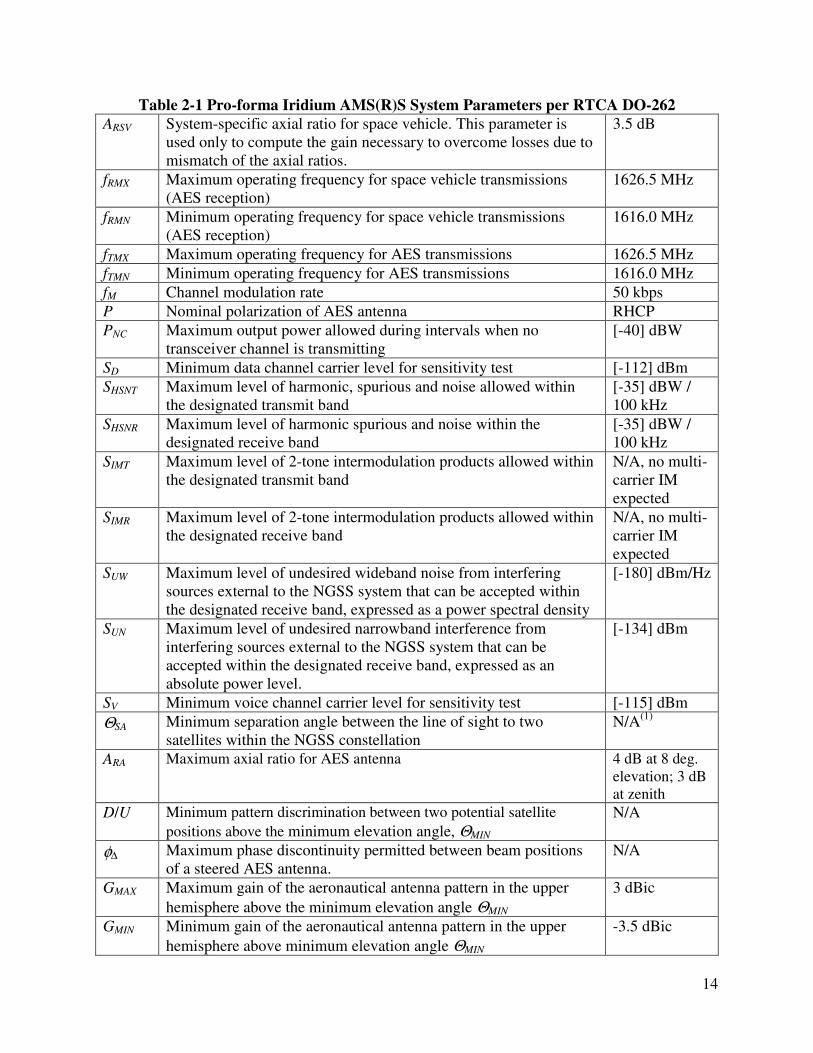
2.3 Aircraft Earth Station RF Characteristics The Iridium AES shall meet AES application requirements, regarding AES antenna and transceiver subsystems, as stated in Section 2.2.3.1 of RTCA DO-262. The pro-forma declaration of Iridium AMS(R)S RF system performance is provided in Table 2-1 per RTCA DO-262.
2.3.1 Antenna Characteristics and Performance AES antenna shall have characteristics and performance as any Iridium certified aeronautical antenna. It shall have an input impedance of 50 ohm and an antenna beam pattern of rotationally symmetric cardioid pointing to the sky. Given the LEO nature of the Iridium system, no antenna steering is recommended.

11
The Iridium AES shall meet AES antenna requirements as stated in Section 2.2.3.1.1 of RTCA DO-262 and antenna performance parameters in Table 2-1 of this document.
2.3.1.1 Coverage Volume The AES antenna system shall be installed to meet performance requirements for transmitting and receiving over a coverage volume of 360 degrees of azimuth and from 8.2 to 90 degrees in elevation from a horizontal plane for aircraft in straight and level flight.
2.3.1.2 Polarization and Axial Ratio The uplink electromagnetic energy shall be right-hand circularly polarized (RHCP), with an axial ratio of no greater than: 3.0 dB for elevation angles greater than 30 degrees, 4.0 dB for elevation angles less than 30 degrees, when measured in free space over the specified bandwidth for all values of local azimuth angle and for elevation angles from the specified minimum elevation angle to 90 degrees relative to the local horizon.
2.3.1.3 Gain The AES antenna system shall have a weighted average minimum gain of 0 dBic according to the weight distribution of elevation angle [AIS], a -3.5 dBic minimum gain at 8 degree elevation and a 3 dBic maximum gain at 90 deg elevation.
2.3.1.4 Passband The AES antenna system shall cover the frequency band of 1616-1626.5 MHz.
2.3.1.5 Voltage Standing Wave Ratio The AES antenna system shall have a Voltage Standing Wave Ratio better than 1.8:1.
2.3.1.6 Intermodulation Performance The AES antenna system shall introduce no additional intermodulation distortion in the communication link. For a dual-channel unit AES, a single dual-channel antenna shall be used.
2.3.2 Transmitter Requirements The Iridium AES shall meet AES transmitter requirements as stated in Section 2.2.3.1.2.1 of RTCA DO-262 and transmitter performance parameters in Table 2-1 of this document. The Iridium AES shall not cause harmful interference to satellite navigation receiver and other AMS(R)S receiver where such receiver is operated on the same aircraft as the AES.
2.3.2.1 EIRP Limits The minimum value of EIRP per carrier in the direction of the satellite, when commanded to the maximum setting, shall be 5.0 dBW over all elevation angles and 8.5 dBW weighted average over all elevation angles. The AES shall meet maximum carrier output level per Table 2-2 of RTCA DO-262 assuming a minimum isolation of 40 dB [TBR].

12
2.3.2.2 Intermodulation Performance Since a multi-carrier AES is to be handled by a multi-channel antenna, the Iridium AES shall introduce no additional intermodulation distortion in the communication link.
2.3.2.3 Spurious Emission The Iridium AES transmitter shall meet the harmonics, discrete spurious, and noise density requirement as specified in Section 2.2.3.1.2.1.5, in particular Tables 2-5, 2-6 and Figures 2-2, 2-3, of RTCA DO-262. Additional filtering external to the ISU might be required to provide additional attenuation to meet the low frequency region requirement.
2.3.2.4 Carrier-off Level When the AES is not transmitting, i.e., when in receive mode or when powered but not in call, the emissions across the band 1605-1666.5 MHz shall be -40 dBW or less.
2.3.2.5 Power Control Uplink and downlink power control are utilized for the Iridium subscriber link to maintain link quality while preserving transmit power of both Iridium Satellites and ISUs. This power control is only adopted for circuit-switched voice channels and not for circuit-switched data channels. Since no external control is provided, the power control function is transparent to the user of the ISU.
2.3.2.6 On-Channel Output Spectrum The output spectrum of a single modulated carrier shall satisfy the in-band requirements of the [AIS].
2.3.2.7 Transmitter Operation in Moving Aircraft The AES shall comply with the satellite network interface requirement and aircraft speed requirement as specified in Section 2.2.3.1.2.1.10 of RTCA DO-262.
2.3.3 Receiver Requirements The Iridium AES shall meet AES receiver requirements as stated in Section 2.2.3.1.2.2 of RTCA DO-262 and receiver performance parameters in Table 2-1 of this document.
2.3.3.1 Receiver Sensitivity The AES shall comply with voice and data mode receiver sensitivity requirement specified in Section 2.2.3.1.2.2.1 of RTCA DO-262 and SV and SD value of [-115] and [-112] dBm, respectively.
2.3.3.2 Receiver Bandwidth The AES receiver shall meet its requirements for an input carrier frequency anywhere in the range of 1616.0-1626.5 MHz.
2.3.3.3 Rejection of Signals Outside the NGSS Receive Band The AES receiver shall meet the rejection performance requirement as stated in Section 2.2.3.1.2.2.3 of RTCA DO-262.

13
2.3.3.4 Rejection of Carrier Signals Generated by Other AMS(R)S Equipment The AES receiver shall meet the rejection performance requirement as stated in Section 2.2.3.1.2.2.4 of RTCA DO-262. This requirement may require additional filtering external to the Iridium L-band transceiver.
2.3.3.5 Receiver Operation in Moving Aircraft The AES shall comply with the satellite network interface requirement and aircraft speed requirement as specified in Section 2.2.3.1.2.2.5 of RTCA DO-262.
2.3.3.6 Receiver Susceptibility The AES shall comply with the receiver susceptibility requirement as specified in Section 2.2.3.1.2.2.6 of RTCA DO-262.
14
Table 2-1 Pro-forma Iridium AMS(R)S System Parameters per RTCA DO-262 ARSV System-specific axial ratio for space vehicle. This parameter is
used only to compute the gain necessary to overcome losses due to mismatch of the axial ratios.
3.5 dB
fRMX Maximum operating frequency for space vehicle transmissions (AES reception)
1626.5 MHz
fRMN Minimum operating frequency for space vehicle transmissions (AES reception)
1616.0 MHz
fTMX Maximum operating frequency for AES transmissions 1626.5 MHz fTMN Minimum operating frequency for AES transmissions 1616.0 MHz fM Channel modulation rate 50 kbps P Nominal polarization of AES antenna RHCP PNC Maximum output power allowed during intervals when no
transceiver channel is transmitting [-40] dBW
SD Minimum data channel carrier level for sensitivity test [-112] dBm SHSNT Maximum level of harmonic, spurious and noise allowed within
the designated transmit band [-35] dBW / 100 kHz
SHSNR Maximum level of harmonic spurious and noise within the designated receive band
[-35] dBW / 100 kHz
SIMT Maximum level of 2-tone intermodulation products allowed within the designated transmit band
N/A, no multi-carrier IM expected
SIMR Maximum level of 2-tone intermodulation products allowed within the designated receive band
N/A, no multi-carrier IM expected
SUW Maximum level of undesired wideband noise from interfering sources external to the NGSS system that can be accepted within the designated receive band, expressed as a power spectral density
[-180] dBm/Hz
SUN Maximum level of undesired narrowband interference from interfering sources external to the NGSS system that can be accepted within the designated receive band, expressed as an absolute power level.
[-134] dBm
SV Minimum voice channel carrier level for sensitivity test [-115] dBm ΘSA Minimum separation angle between the line of sight to two
satellites within the NGSS constellation N/A(1)
ARA Maximum axial ratio for AES antenna 4 dB at 8 deg. elevation; 3 dB at zenith
D/U Minimum pattern discrimination between two potential satellite positions above the minimum elevation angle, ΘMIN
N/A
φ∆ Maximum phase discontinuity permitted between beam positions of a steered AES antenna.
N/A
GMAX Maximum gain of the aeronautical antenna pattern in the upper hemisphere above the minimum elevation angle ΘMIN
3 dBic
GMIN Minimum gain of the aeronautical antenna pattern in the upper hemisphere above minimum elevation angle ΘMIN
-3.5 dBic

15
LMAX Maximum cable loss between AES antenna port and the AES transceiver input port
3 dB
LMSG Maximum length in octets of user data sequence using Data 2 transmissions
TBD
LSNDP Maximum length in octets of user data contained in a maximum length sub-network dependent protocol data block
TBD
ND Maximum number of simultaneous data carriers 2(2) NV Maximum number of simultaneous voice carriers 2(2) PD Maximum single carrier power for each of ND data carriers in a
multi-carrier capable AES 7 W
PRNG Range over which the AES transmit power must be controlled N/A PSC-SC Maximum burst output power of single carrier AES 7 W PSTEP Maximum acceptable step size for controlling AES transmit power N/A PV Maximum single carrier power for each of NV voice carriers in a
multi-carrier capable AES 7 W
RSC-UD Minimum average single channel user data rate sustainable at a residual packet error rate of 10-6
2.4 kbps
ΘMIN Minimum elevation angle for satellite coverage 8.2 deg. τSW Maximum switching time between electronically steered antenna
patterns. N/A
ρRA Minimum exclusion zone radius necessary for protection of Radio Astronomy
N/A
C/M Carrier-to-multipath discrimination ratio measured at the minimum elevation angle
6 dB
VSWR Maximum Voltage Standing Wave Ratio measured at a single input port of the AES antenna
1.8:1
Notes: (1) Line of sight separation angle depends latitude and specific location of the terminal. (2) ND + NV shall be less than or equal to 2, assuming a dual-carrier antenna unit.

16
3 RF CHANNEL CHARACTERISTICS The RF channel characteristics shall conform to the requirements of the [AIS], which are qualitatively described in the following subsections. The information provided here is for reference only. Since AES is to incorporate Iridium L-band transceiver manufactured and certified by Iridium, the AES developer will not need to be concerned with most of the information stated in this section. The RF channel is transparent to the AES developers and users.
3.1 Channel Multiplexing Channels are implemented in the Iridium system using a hybrid TDMA/FDMA architecture based on TDD using a 90 millisecond frame. Channels are reused in different geographic locations by implementing acceptable co-channel interference constraints. A channel assignment comprises of both a frequency carrier and a time slot.
3.1.1 TDMA Frame Structure The fundamental unit of the TDMA channel is a time-slot. Time-slots are organized into frames. The L-Band subsystem TDMA frame is illustrated in Figure 3-1. The frame consists of a 20.32 millisecond downlink simplex time-slot, followed by four 8.28 millisecond uplink time-slots and four downlink time-slots, which provide the duplex channel capability. The TDMA frame also includes various guard times to allow hardware set up and to provide tolerance for uplink channel operations. The simplex time-slot supports the downlink-only, ring and messaging channels. The Acquisition, Synchronization, and Traffic channels use the uplink time-slots. The Broadcast, Synchronization, and Traffic channels use the downlink duplex time-slots. The L-Band frame provides 2250 symbols per frame at the channel burst modulation rate of 25 ksps. A 2400 bps traffic channel uses one uplink and one downlink time-slot each frame.
Figure 3-1 Iridium TDMA Structure
3.1.2 FDMA Frequency Plan The fundamental unit of frequency in the FDMA structure is a frequency access that occupies a 41.667 kHz bandwidth. Each channel uses one frequency access. The frequency accesses are divided into the duplex channel band and the simplex channel band. The duplex channel band is further divided into sub-bands.

17
3.1.3 Duplex Channel Band The frequency accesses used for duplex channels are organized into sub-bands, each of which contains eight frequency accesses. Each sub-band, therefore, occupies 333.333 kHz (8 x 41.667 kHz). In duplex operation, the Iridium system is capable of operating with up to 30 sub-bands, containing a total of 240 frequency accesses. Table 3-1 shows the band edges for each of the 30 subbands.
Table 3-1 Sub-Band Frequency Allocation Sub-band Lower Edge (MHz) Upper Edge (MHz)
1 1616.000000 1616.333333 2 1616.333333 1616.666667 3 1616.666667 1617.000000 4 1617.000000 1617.333333 5 1617.333333 1617.666667 6 1617.666667 1618.000000 7 1618.000000 1618.333333 8 1618.333333 1618.666667 9 1618.666667 1619.000000 10 1619.000000 1619.333333 11 1619.333333 1619.666667 12 1619.666667 1620.000000 13 1620.000000 1620.333333 14 1620.333333 1620.666667 15 1620.666667 1621.000000 16 1621.000000 1621.333333 17 1621.333333 1621.666667 18 1621.666667 1622.000000 19 1622.000000 1622.333333 20 1622.333333 1622.666667 21 1622.666667 1623.000000 22 1623.000000 1623.333333 23 1623.333333 1623.666667 24 1623.666667 1624.000000 25 1624.000000 1624.333333 26 1624.333333 1624.666667 27 1624.666667 1625.000000 28 1625.000000 1625.333333 29 1625.333333 1625.666667 30 1625.666667 1626.000000
The Iridium system reuses duplex channels from beam to beam when sufficient spatial isolation exists to avoid interference. Channel assignments are restricted so that interference is limited to acceptable levels. The minimum group of duplex channels that can be allocated to an antenna beam is called a reuse unit pair. A reuse unit consists of one time-slot and the eight contiguous frequency accesses of a sub-band for a total of eight channels. The frequency accesses are numbered 1 through 8 from lowest to highest frequency. A reuse unit pair consists of an uplink reuse unit and a downlink reuse unit.

18
Table 3-2 lists the lower, upper and center frequencies for each of the 8 frequency accesses within a reuse unit. These frequencies are relative to the lower edge of the sub-band defined in Table 3-1. Reuse unit pairs can be assigned to a beam, reclassified or activated/deactivated at the beginning of L-band frames. Dynamic beam assignment and reclassification are used to provide additional capacity to beams that have heavy traffic loading.
Table 3-2 Reuse Unit Frequency Accesses Frequency
Access Number
Lower Edge Frequency
(kHz)
Upper Edge Frequency
(kHz)
Center Frequency
(kHz)
1 0.000 41.667 20.833 2 41.667 83.333 62.500 3 83.333 125.000 104.167 4 125.000 166.667 145.833 5 166.667 208.333 187.500 6 208.333 250.000 229.167 7 250.000 291.667 270.833 8 291.667 333.333 312.500
3.1.4 Simplex Channel Band A 12-frequency access band is reserved for the simplex (ring alert and messaging) channels. These channels are located in a globally allocated 500 kHz band between 1626.0 MHz and 1626.5 MHz. These frequency accesses are only used for downlink signals and they are the only L-Band frequencies that may be transmitted during the simplex time-slot. As shown in Table 3-3, four messaging channels and one ring alert channel are available during the simplex time-slot.
Table 3-3 Simplex Frequency Allocation
Channel Number
Center Frequency (MHz) Allocation
1 1626.020833 Guard Channel 2 1626.062500 Guard Channel 3 1626.104167 Quaternary Messaging 4 1626.145833 Tertiary Messaging 5 1626.187500 Guard Channel 6 1626.229167 Guard Channel 7 1626.270833 Ring Alert 8 1626.312500 Guard Channel 9 1626.354167 Guard Channel 10 1626.395833 Secondary Messaging 11 1626.437500 Primary Messaging 12 1626.479167 Guard Channel

19
3.2 L-Band Transmission Characteristics All L-Band uplink and downlink transmissions used in the Iridium System use variations of 25 kilosymbols-per-second (ksps) QPSK modulation, and are implemented with 40% square root raised cosine pulse shaping. The variations of QPSK used include differential encoding (DE-QPSK) and BPSK, which is treated as a special case of QPSK. Figure 3-2 illustrates the relevant FDMA frequency characteristics.
1616 MHz 1626.5 Mhz31.5 kHz
41.67 kHz 50 kbps–QPSK RC alpha=.4
Figure 3-2 FDMA Frequency Plan
The modulation structure used for the uplink and downlink traffic data includes differential encoding to allow demodulators to rapidly reacquire phase and resolve phase ambiguities in case there is a momentary loss of phase-lock due to a link fade. Certain signaling, control, and traffic applications implement error correction coding to improve the link bit error rate, with characteristics tailored for each application certain traffic and signaling message applications. The vocoder algorithm provides its own interleaving and forward error correction. Most of the administrative transmissions used in granting access to and exerting control of the L-Band link implement their own internal error correction and interleaving. The Iridium L-Band protocol does not provide forward error correction to user generated data transmitted in the payload. Such data is protected from transmission errors by a 24-bit Frame Check Sequence transmitted in every traffic burst containing a data payload (as opposed to a voice payload). If the Frame Check Sequence does not validate that the payload data was correctly received, the L-Band Protocol implements error by retransmission of the Iridium frame. Erroneous information, i.e., payload data that does not satisfy the Frame Check Sequence, is not passed to the end user. Therefore, a decrease in channel quality which causes any increase in channel bit-error-rate results in an increase in the number of retransmissions and a corresponding decrease in the number of user-generated bits provided to the end user. Iridium aeronautical service has been designed to provide a minimum throughput of user generated information of 2400 bps [99.5%] of the time, gracefully degrading without user intervention to 600 bps at the [99.97th percentile]

20
3.2.1 Downlink Channels Traffic, broadcast, synchronization, ring alert, and messaging channels all use DE-QPSK modulation with 40% square root raised cosine pulse shaping. In all cases, the burst transmission rate is 25 ksps and provides a burst data rate of 50 kbps.
3.2.2 Uplink Channels Uplink traffic channels use DE-QPSK modulation with 40% square root raised cosine pulse shaping and burst transmission rates of 25 ksps, or 50 kbps. Uplink acquisition and synchronization channels both use DE-BPSK with 40% square root raised cosine pulse shaping and burst transmission rates of 25 ksps, or 25 kbps. BPSK is used because it provides a 3 dB link advantage, which improves the burst acquisition probability. Traffic channels operate with adaptive power control, discussed below, which acts to limit power transmissions beyond what is required for good voice and data quality.
3.2.3 Power Control The L-Band link has been designed for a threshold channel bit error of 0.02, which is sufficient to support voice services. This level is achieved at an Eb/(No+Io) of 6.1 dB in clear line of sight conditions. The basic Iridium System will operate with an average link margin of 15.5 dB above this level, as required to mitigate fading due to the Rayleigh multipath and shadowing typical of handheld phone operation in urban environments. Under good channel conditions, this level is reduced by adaptive power control. Even under adaptive power control, link margin is maintained to mitigate fades that are too short in duration to be compensated for by the power control loop. For Iridium aeronautical service, a much more conservative approach has been taken to specifying L-Band link performance. This is permitted because the aeronautical terminal operates under conditions that favor multipath statistics following a Rician, rather than a Rayleigh, probability density function. Using the guidelines of RTCA DO-215A, a significant portion of the large link margin available for non-aeronautical users has been dedicated to (1) interference protection, (2) Rician multipath mitigation, and (3) overcoming probabilistic system losses. Once these additional link allowances were made, the aeronautical radiated power and sensitivity were adjusted to minimize the size and power consumption of avionics. Under good channel conditions, i.e., when there is limited interference, then multipath and the probabilistic losses are not excessive, adaptive power control is utilized to minimize the transmitted power in both up and down links. Adaptive power control uses a closed loop algorithm in which the space vehicle and AES receivers measure received Eb/No and command the transmitters to adjust their transmitted power to the minimum value necessary to maintain high link quality. When the entire available link margin is not required to mitigate channel conditions, adaptive power control has the effect of reducing system power consumption. There are slight differences in the power control algorithms used for voice and data operations. For data operations, the algorithm is biased toward higher power levels and does not use adaptive power control, hence ensuring low channel bit error rates and high user throughput.
21
3.3 Radiated Power Spectral Density The in-band, on-channel Effective Isotropic Radiated Power Spectral Density shall comply with the requirements of the [AIS].
3.3 Demodulator Performance The received energy-per-channel-bit-to-noise-plus-interference-density ratio Eb/(No+Io) required to achieve a particular BER on any downlink channel shall be within 3.0 dB of the Eb/(No+Io) theoretically required to achieve that BER, for differentially encoded QPSK in an ideal channel, over a BER range of 10-1 to 10-6, for a signal that includes all degradation introduced by the transmitter and receiver.
3.4 Acquisition Performance The probability of losing a satellite-ASE downlink burst due to missed detection, failure to acquire and loss of synchronization shall not exceed 0.0005 for a received signal strength relative to a zero dBi antenna at the receiver antenna of -147.7 dBW with modulation, filtering, channel bit rate, and interference as specified in [AIS], with a sky temperature of 172 K, and when weighted averaged from the minimum elevation angle to 90 degrees with the probability density function of elevation angle specified in [AIS] as the weighting function.

22
4 CHANNEL FORMAT TYPES AND RATES The communications channel characteristics shall conform to the requirements of the [AIS], which are qualitatively described in the following subsections. The information provided here is for reference only. Since AES is to incorporate Iridium L-band transceiver manufactured and certified by Iridium, the AES developer will not need to be concerned with most of the information stated in this section. The communications channel characteristics is transparent to the AES developers and users.
4.1 General Each Iridium communications channel consists of a time-slot and a carrier frequency. Channels provided by the system can be divided into two broad categories: bearer service channels and system overhead channels. Bearer service channels include traffic channels and messaging channels, while system overhead channels include ring alert channels, broadcast channels, acquisition and synchronization channels. A specific time-slot-and-frequency combination may be used for several types of channels, depending on what specific activity is appropriate at each instant. Each time-slot-and-frequency combination is only used for one purpose at a time. Figure illustrates the hierarchy of Iridium channel types. Iridium aeronautical services utilize only the indicated channel types.
IRIDIUMCHANNELIRIDIUM
CHANNEL
TRAFFICCHANNEL
MESSAGECHANNEL
Frequency Access Time Slot Access
SYSTEMOVERHEADCHANNEL
SYSTEMOVERHEADCHANNEL
BEARERSERVICECHANNEL
BEARERSERVICECHANNEL
RINGCHANNEL
BRDCASTCHANNEL
ACQ’SNCHANNEL
SYNCCHANNEL
VOCODEDCHANNEL
BYPASSCHANNEL
= LOW LEVEL CHANNELSUSED BY IRIDIUM AERO SERVICES
Figure 4-1 Iridium Channel Structure Hierarchy
In the discussions that follow, the term "channel" always refers to a time-slot-and-frequency combination. The terms "frequency" or "frequency access" will be used to denote the specific radio frequency of an individual channel.

23
4.2 Definitions and Descriptions of Channel Types The Iridium System has four overhead channels; the overhead channels are ring channel, broadcast channel, acquisition channel, and sync channel. The ring channel is a downlink-only channel used to send ring alert messages to individual subscriber units. Its downlink frequency is globally allocated in order to be the same known frequency throughout the world. The ring channel uses a time division format to send ring alert messages to multiple subscriber units in a single frame. Broadcast channels are downlink channels used to support the acquisition and handoff processes. These channels provide frequency, timing, and system information to ISUs before they attempt to transmit an acquisition request. In addition, broadcast channels provide downlink messages which acknowledge acquisition requests and make channel assignments. Finally, broadcast channels are used to implement selective acquisition blocking to prevent local system overloads. Acquisition channels are uplink-only channels used by individual subscriber equipment to transmit an acquisition request. These channels use a slotted ALOHA random access process. The time and frequency error tolerances are larger for an acquisition channel to allow for initial frequency and timing uncertainties. ISUs determine which acquisition channels are active by monitoring the broadcast channel. The sync channel is a duplex channel used by the ISU to achieve final synchronization with an SV before it begins traffic channel operation. The sync channel occupies the same physical channel time slots and frequency accesses as the traffic channel that the ISU will occupy when the sync process is complete. During the sync process, the SV measures the DTOA and DFOA of the uplink sync burst and sends correction information to the ISU in the downlink sync burst. A synchronization channel is assigned to an ISU by the SV. The synchronization procedure is accomplished by the ISU transmitting an uplink burst which the SV measures for time and frequency error relative to the assigned channel. The SV sends time and frequency corrections for the latest uplink burst over the downlink channel. This process is repeated until the SV determines that the ISU transmit time and frequency are within the tolerance for a traffic channel. When this occurs, the SV transmits a message to that effect to the ISU and reconfigures the channel for traffic channel operation. The Iridium subscriber link provides two basic types of bearer service channels: traffic channels and messaging channels. Messaging channels support downlink only simplex messaging service. This service carries numeric and alphanumeric messages to Message Termination Devices such as Iridium pagers. The Iridium aeronautical service does not utilize the simplex messaging services. Traffic channels support duplex services; these include portable mobile telephony and a variety of duplex bearer data services. Each traffic channel consists of an associated uplink and downlink channel. A duplex user has exclusive use of the assigned channels until service terminates or until handed off to a different channel.

24
4.3 Traffic Channel for Iridium AMS(R)S Traffic channels provide the two way connections between space vehicles and subscriber equipment that support the Iridium services. These channels transport the system voice and data services along with the signaling data necessary to maintain the connection and control the services. The uplink and downlink traffic channels use identical burst structures. Each burst is 8.28 ms long and contains 414 channel bits. The bursts are divided into four major data fields: Preamble, Unique Word, Link Control Word and Payload Field. The preamble and unique word are used in the receiving demodulator for burst acquisition. The preamble and unique word patterns are different for the uplink and downlink. The link control word provides a very low data rate signaling channel that is used to support link maintenance, the associated control channel and handoff. The payload field furnishes the primary traffic channel which carries the mission data and signaling messages. The link control word field provides a low rate signaling channel used for control of the subscriber link. The uplink and downlink traffic channels use the same link control word format. The link control word is used to support link maintenance, handoff and the ACK/NAK of the associated control channel transmission protocol. The link control word field is protected by forward error control (FEC) code. The traffic channel payload field provides the primary traffic channel. This field carries the mission data and mission control data. This field supports a channel bit rate of 3466.67 bps. Typically error correction coding and other overhead functions provide a nominal information throughput on this channel of 2400 bps. Mission data may be either vocoded voice data or data services. For voice service, the proprietary Iridium vocoder uses FEC to ensure good quality vocoded voice performance tailored for the Iridium communication channels. For data service, the L-band transport employs a frame check sequence to provide essentially error free data transport service. The information provided in this subsection is for reference only. The user of the ISU is buffered from the internal working, signaling and protocol details of the traffic channel as well as acquisition, synchronization and other physical layer/channel processing and management functions of the ISU. The basic interface to the ISU and the circuit switched channel setup/teardown are provided at a modem application level using the Iridium AT command set. Some Iridium data services also provide additional service specific interfaces to facilitate user access. In summary, the Iridium communication channel appears to the end users as an efficient and reliable data transport. Traffic channel is to provide circuit mode voice and data service and connection oriented packet data service for the Iridium AMS(R)S application. A single-carrier Iridium AES shall set up a single circuit-switch channel for either voice or data service using a single ISU. A multiple-carrier Iridium AES shall set up multiple circuit-switch channels for either voice or data services by utilizing multiple ISUs with the AES. Packet data

25
channels, if provided, shall be managed as connection oriented switched virtual circuits transported by single (or multiple) circuit-switch data channel(s) with nominal throughput of 2.4 kbps.
26
5 CIRCUIT-MODE SERVICES
5.1 Circuit-mode General Requirements Circuit-mode voice and/or data services, if provided by the Iridium AES, shall comply with the requirements of Section 2.2.3.7 of RTCA DO-262. The AES may provide voice communications capability to the cockpit and/or the passenger cabin areas. Note: At the time this document was developed, RTCA had not yet published a MASPS dealing with safety-voice capabilities and operations. Until such a document is available, AES manufacturers are encouraged to follow the recommendations RTCA DO-231 when implementing safety voice capabilities.
5.2 Circuit-mode Priority, Precedence and Preemption Circuit-mode voice and data service shall comply with the priority, precedence and preemption requirements established in Section 2.2.3.3 of RTCA DO-262. The AES shall establish the priority structure shown in Table 2-7 of RTCA DO-262. AMS(R)S circuit-mode communications shall utilize Iridium Acquisition Class 14. AMS(R)S circuit-mode communications shall set the Priority Class within Acquisition Class 14 at the time of circuit set-up, and shall maintain that priority class for the duration of the active circuit.
5.3 Circuit-mode Performance Requirements Circuit-mode service performance is tabulated in Table 1-2, pro-forma declaration of system parameters. For AMS(R)S voice calls, the distribution of the Call Establishment Delay measured from the time a call request is received at the Gateway until the call setup process has been completed in the AES shall not exceed 20 seconds at the 95th percentile for both ground-originated and air-originated calls.
5.4 Circuit-mode Voice Encoding Algorithm The proprietary Iridium vocoder is tailored to the Iridium communication channel and provides good quality audio performance with a nominal Mean Opinion Score (MOS) of [3.5] under typical operating and channel condition. The vocoder is mandatory for circuit-switched voice traffic and is buffered from the AES developers.
5.5 Circuit-mode Procedures The Iridium AES sets up a circuit-switched voice or data call by dialing a voice or data call number using the Iridium AT command: ATDnx..x where n is a Dial Modifier and x is a number. An example of how to make and disconnect a voice call is given below:
ATD1234567890; (dial remote phone)
27
OK (call connected; phone stays in command mode)
< ... conversation ... >
ATH (hangup call)
OK
An example of how to make a data call is given below:
AT+CBST=6,0,1 (asynchronous modem 4800 bps and IRLP)
OK
AT+CR=1 (enable reporting)
OK
ATD1234567890 (dial remote modem)
+CR: REL ASYNC
CONNECT 9600 (call connected at DTE rate of 9600)
The ISU is capable of accepting mobile terminated data calls. The following is a sequence of commands that can be used to establish the connection.
RING (indicates arrival of call request)
ATA (manually answer the call)
CONNECT 9600 (call connected at DTE rate of 9600)
To automatically answer a call, register 0 should be set to a non-zero value.
ATS0=2
RING
CONNECT 9600 (call connected at DTE rate of 9600)
The Iridium ISU AT Command Reference provides descriptions of all the Iridium AT commands for proper interfacing to the ISU. The Iridium AES shall provide interworking functions between the end users/applications and the Iridium circuit switched services to meet the AMS(R)S circuit-mode service requirement and specifications.
5.6 Telephony Numbering Plan The Iridium AMS(R)S services shall support the use of ICAO 24-bit aircraft ID. The AES and the terrestrial user system shall provide mapping between the ICAO aircraft IDs and the Iridium ISU number.

28
6 SATELLITE SUBNETWORK LAYER DATA SERVICES
6.1 General Provisions Iridium offers a multitude of data services that can be used to support AMS(R)S packet data service. All Iridium data services provide a transparent and reliable data transport. It is up to the AES developer to decide the exact implementation of the packet mode data service per the guidance and specifications of RTCA DO-270 and RTCA DO-262. Packet-mode data services shall provide an Aeronautical Telecommunications Network- (ATN-) compliant protocol, or the Data-2 protocol, or both, as defined in RTCA DO-262 Section 2.2.3.6. ATN-compliant protocols implement a subnetwork interface in which the AES contains the physical layer, link-layer and network layer functionality, where the layers are defined according to the Open System Interconnect terminology. One particular implementation that is known to be ATN-compliant is an ISO-8208 compliant interface. If the AES implements an ISO-8208 compliant interface, that interface shall comply with the requirements of Appendix B of RTCA DO-262. Data-2 provides a link-level service only. In Data-2 implementations, a minimum AES provides only the physical and link layer functionality. Management of priority and preemption are implemented in higher level entities external to the AES.
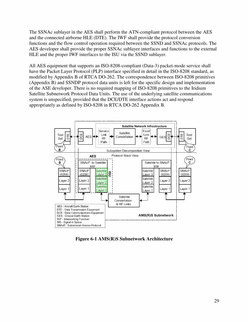
6.2 Packet-data System Architecture Figure 6-1 illustrates the Iridium AMS(R)S satellite subnetwork architecture with the AES and the ISU highlighted. The requirements of this section shall be interpreted as applying to communications between Point B and Point C of Figure 6-1, where 128 octets are provided at the input of Point B, and received at the output of Point C, or provided at the input of Point C and received at the output of Point B. Figure 6-2 zooms in and focuses on the AES and its data interface to the external higher layer entity. ISO-style protocol stacks associated with ATN-compliant operations are assumed for illustrative purpose only in both figures. The Satellite Subnetwork Layer (SSNL) in the AES shall offer connection-oriented packet data service to the Higher Layer Entities (HLEs) by facilitating satellite subnetwork switched virtual circuits (SVCs) with its peer entity in the subnetwork GES function. The SSNL in the AES shall support the following three main functions:
1. The Satellite Subnetwork Dependent (SSND) sublayer. 2. The Satellite Subnetwork Access (SSNAc) sublayer. 3. The Satellite Subnetwork InterWorking Function (IWF).
The SSND sublayer shall perform the SSND protocol (SSNDP) between the AES and a GES. The SSND sublayer communication is completely handled by the Iridium network. Interfaces to the SSND sublayer are defined by the interface control document of each Iridium data service.
29
The SSNAc sublayer in the AES shall perform the ATN-compliant protocol between the AES and the connected airborne HLE (DTE). The IWF shall provide the protocol conversion functions and the flow control operation required between the SSND and SSNAc protocols. The AES developer shall provide the proper SSNAc sublayer interfaces and functions to the external HLE and the proper IWF interfaces to the ISU via the SSND sublayer. All AES equipment that supports an ISO-8208-compliant (Data-3) packet-mode service shall have the Packet Layer Protocol (PLP) interface specified in detail in the ISO-8208 standard, as modified by Appendix B of RTCA DO-262. The correspondence between ISO-8208 primitives (Appendix B) and SSNDP protocol data units is left for the specific design and implementation of the ASE developer. There is no required mapping of ISO-8208 primitives to the Iridium Satellite Subnetwork Protocol Data Units. The use of the underlying satellite communications system is unspecified, provided that the DCE/DTE interface actions act and respond appropriately as defined by ISO-8208 in RTCA DO-262 Appendix B.
Figure 6-1 AMS(R)S Subnetwork Architecture
ISU
AES

30
Figure 6-2 Satellite Subnetwork Architecture (Airborne Side)
6.3 Packet-data Performance The connection establishment delay shall not exceed [33] seconds. For communications identified as Acquisition Class 14 and Priority Class 3, the mean transfer delay (transit delay) shall not exceed [23] seconds in either the air-to-ground or ground-to-air direction. For communications identified as Acquisition Class 14 and Priority Class 0 or any lower Acquisition Class, the mean transfer delay (transit delay) shall not exceed [28] seconds in either the air-to-ground or ground-to-air direction. For communications identified as Acquisition Class 14 and Priority Class 3, the 95th percentile of the transfer delay shall not exceed [23] seconds in either the air-to-ground or ground-to-air direction. For communications identified as Acquisition Class 14 and Priority Class 0 or any lower Acquisition Class, 95th percentile of the transfer delay shall not exceed [28] seconds in either the air-to-ground or ground-to-air direction. The connection release delay shall be less than [25] seconds for 95% of all release actions. The residual packet error rate, including erroneously addressed and undelivered packets, shall not exceed 1 x 10⁻⁶ in either the air-to-ground or ground-to-air direction.
ISU

31
Packet data performance is summarized in Table 1-2, pro-forma declaration of Iridium AMS(R)S system parameters.
6.4 Packet-data Priority, Precedence and Preemption Since the Iridium data services only provide a transparent and reliable transport for packet data, it is left for the AES developer to provide the packet data priority, precedence, and preemption. If packet-mode data services are implemented over circuit mode connections, the requirements of RTCA DO-262 Section 2.2.3.3.2 shall apply to the circuit mode connections themselves. Within such a circuit mode connection, packet priority, precedence and preemption shall be in accordance with Table 2-7 of RTCA DO-262 Section 2.2.3.3.2. The AES shall provide for prioritization of data packets input at the AES data port(s). The AES shall provide at least three levels of priority for safety communications, per RTCA DO-262 Section 2.2.3.3 for packet data. Transmission preemption, if necessary, shall be effected by changing the order of data transmission such that the data units of the internal protocols comprising the higher-priority message are transmitted before corresponding lower-priority data units. Any reordering necessary to comply with this requirement shall take effect immediately upon completion of currently active data unit transmission. Preemption of lower-priority messages, if necessary, shall be effected by any means necessary to preserve the higher-priority message(s).
6.5 Satellite Subnetwork-dependent Protocol Services and Operations The combination of the Iridium Satellite Subnetwork Dependent Protocol and the Iridium Satellite Layer 2 protocol provides a reliable link service to assist the overall AMSS air-to-ground subnetwork in delivering high integrity data. The Iridium SSNDP provides the additional error control mechanisms to assure a residual packet error rate of 1x10⁻⁶ or less for a standard 128-octet message. The Iridium SSNDP supports the following:
1. A byte and code independent transport. 2. Maintaining the sequence and order of data (i.e. data submitted to the SSNDP for
transmission shall arrive at the destination peer in the same order it was transmitted). 3. Informing its interworking function whenever its connectivity with the satellite network
changes.
The Iridium Router-Based Unrestricted Digital Interworking Connectivity Solution (RUDICS) service is a fast, efficient, and reliable circuit switched data service that can be used to provide the Iridium AMS(R)S packet data services.
6.5.1 Iridium RUDICS Service The Iridium RUDICS service is an enhanced Gateway termination and origination capability for circuit switched data calls across the Iridium Satellite network. RUDICS offers an optimized data connection service for various end to end data applications or solutions.

32
There are four key benefits of using RUDICS as part of a data solution over conventional PSTN circuit switched data connectivity or mobile-to-mobile data solutions:
1. Elimination of analog modem training time, hence faster connection establishment time. 2. Increased call connection quality, reliability, and maximized throughput. 3. Protocol independence. 4. Both Mobile Originated and Mobile Terminated calls are rated at the same rate.
Remote applications use AT Commands to control a circuit switched data capable ISU. Figure 6-3 illustrates the call set up process of a Mobile Originated (MO) data call. The remote application dials a customer specific Iridium number, which connects the call through the Siemens D900 telephony switch, to the RUDICS server. The customer specific number is assigned and provisioned by Iridium. Each ISU is authenticated using Calling Line Identification for the RUDICS customer specific number that it dialed. Once authenticated the call is routed over the terrestrial connection to a pre-configured Internet Protocol (IP) address and Port where the user host application server is. The RUDICS service supports the follow service transport types: TCP/IP encapsulation, PPP, and MLPP.
Figure 6-3 Iridium RUDICS Mobile Originated Data Call Setup
The Host application can make a Mobile Terminated call by opening a Telnet session to the RUDICS server. Once authenticated, a series of AT Commands are used to connect to the remote ISU and establish a circuit switched data call. Mobile Terminated access must specifically be requested at the time of the initial configuration and set up. Connectivity between the Iridium Gateway and the end user Host Server can be via a number of options, including:

33
• Internet • Internet with Virtual Private Network • Private leased line such as:
o Frame Relay o T1/E1 Leased Line
Additionally, the RUDICS capability offers the capability for Multi-Link Point to Point Protocol (MLPPP). This is where multiple ISUs can be used to send data simultaneously and the data can be delivered in an N x 2400 bps PPP connection.
6.6 ISO-8208 Protocol Operations Appendix B of RTCA DO-262 specifies ISO-8208 priority mapping, ISO-8208 compliant protocol implementation, AES operation as DCE in ISO-8208 environment, state transition of the DCE state machine, and other relevant information regarding the ISO-8208 protocol. An AES providing ISO-8208 compliant interfaces and operations shall meet requirements specified in Appendix B of RTCA DO-262.

34
7 AIRCRAFT EARTH STATION (AES) MANAGEMENT
7.1 AES Management Functions The Iridium AES management functions shall include the function performed in the AES to initiate, manage, and terminate circuit-mode voice and/or data services and packet mode data services, if provided. It shall conform to the requirements of recovery from primary power interruption and shall provide failure/status indication, as specified in Sections 2.2.3.8 and 2.2.3.9 of RTCA DO-262.
7.2 AES Management Interfaces The AES management shall provide for interfacing to the following AES entities:
• Circuit-mode services • Packet data services