icap q operating manual - thermo fisher scientific · pdf filecontacting us assistance thermo...
TRANSCRIPT

Part of Thermo Fisher Scientific
Revision B - 1288090
Thermo Fisher Scientific
iCAP QOperating Manual
© 2012 Thermo Fisher Scientific Inc. All rights reserved.Original Operating Instructions
Leybonol and Sogevac are a registered trademarks of Oerlikon Leybold Vacuum GmbH. Santoprene is a registered trademark of Monsanto, Inc. Viton is a registered trademark of DuPont Dow Elastomers.
All other trademarks are the property of Thermo Fisher Scientific Inc. and its subsidiaries.
Thermo Fisher Scientific Inc. provides this document to its customers with a product purchase to use in the product operation. This document is copyright protected and any reproduction of the whole or any part of this document is strictly prohibited, except with the written authorization of Thermo Fisher Scientific Inc.
Release History: Revision A released in March 2012.Revision B released in June 2012.
Contacting UsAssistance
Contacting Us
There are several ways to contact Thermo Fisher Scientific.
AssistanceFor technical support and ordering information, visit us on the Web:
www.thermoscientific.com/ms
Service contact details for customers in Europe are available under:
www.unitylabservice.com
Customer Information ServiceThe Customer Information Service site cis.thermo-bremen.com is aimed at providing instant access to latest software updates and manuals, application reports, and brochures.
Thermo Fisher Scientific recommends that you register with the site as early as possible. To register, visit register.thermo-bremen.com/form/cis and fill in the registration form. Once your registration has been finalized, you will receive confirmation by e-mail.
Suggestions to the Manual❖ To suggest changes to this manual
• Please send your comments to:
Editors, Technical DocumentationThermo Fisher Scientific (Bremen) GmbHHanna-Kunath-Str. 11
28199 Bremen
Germany
• Send an e-mail message to the Technical Editor at
You are encouraged to report errors or omissions in the text or index.Thank you.
Thermo Fisher Scientific iCAP Q Operating Manual (P/N 1288090, Revision B) i

Contacting UsSuggestions to the Manual
ii iCAP Q Operating Manual (P/N 1288090, Revision B) Thermo Fisher Scientific
Contents
Chapter 1 Using this Manual.....................................................................1-1About this Manual ............................................................ 1-1Typographical Conventions .............................................. 1-2
Signal Word................................................................... 1-2Viewpoint Orientation................................................... 1-2Data Input ..................................................................... 1-2Topic Headings.............................................................. 1-3
Reference Documentation................................................. 1-4
Chapter 2 Scope of Delivery......................................................................2-1Standard System Components .......................................... 2-1Optional System Components .......................................... 2-2
Chapter 3 System Description...................................................................3-1General Description .......................................................... 3-2
Instrument Layout ......................................................... 3-3Sample Introduction System ............................................. 3-4
Peristaltic Pump............................................................. 3-4Nebulizer ....................................................................... 3-5Spray Chamber .............................................................. 3-5Injector .......................................................................... 3-6Torch............................................................................. 3-6
Interface ............................................................................ 3-7Sample Cone and Skimmer Cone .................................. 3-7Extraction Lens .............................................................. 3-8
Ion Optics......................................................................... 3-9RAPID Lens................................................................... 3-9QCell ............................................................................. 3-9DA Assembly ............................................................... 3-10
Mass Analyzer ................................................................. 3-10Quadrupole.................................................................. 3-10Detector....................................................................... 3-10
Vacuum System .............................................................. 3-11Forepump .................................................................... 3-12Turbomolecular Pump................................................. 3-12Pressure Measurement.................................................. 3-12
Gas Supply...................................................................... 3-13Connections................................................................. 3-13Plasma and Cooling Gas .............................................. 3-14CCT Gas ..................................................................... 3-15Additional Gas ............................................................. 3-17
Thermo Fisher Scientific iCAP Q Operating Manual (P/N 1288090, Revision B) iii
Contents
Cooling System............................................................... 3-19Connections for Water Supply ..................................... 3-19Recirculating Chiller .................................................... 3-20
Exhaust System ............................................................... 3-21Connections.................................................................... 3-22
Main Power Switch...................................................... 3-23Power Connections ...................................................... 3-23Fore Vacuum Pump Connections ................................ 3-24Connection to Computer and Peripherals .................... 3-25
Chapter 4 Safety .......................................................................................... 4-1Safety Symbols and Signal Words in this Manual.............. 4-2
Observing this Manual................................................... 4-2Safety Symbols on the Instrument..................................... 4-3Rating Plate....................................................................... 4-5Intended Use..................................................................... 4-6
Qualified Personnel........................................................ 4-7Permitted Materials........................................................... 4-7Electrical Safety Precautions .............................................. 4-8Residual Hazards............................................................... 4-9Personal Protective Equipment ....................................... 4-10EMC Information........................................................... 4-11In Case of Emergency ..................................................... 4-12
Chapter 5 System Setup............................................................................. 5-1Safety Guidelines for Installation....................................... 5-2Placing the System ............................................................ 5-3
Instrument Dimensions ................................................. 5-3Moving the Instrument .................................................. 5-4Workbench for Instrument ............................................ 5-5
Laboratory Conditions ...................................................... 5-7Power Supply ................................................................. 5-7Gas Supply..................................................................... 5-7Laboratory Temperature ................................................ 5-8Humidity ....................................................................... 5-8Ventilation and Fume Exhaust ....................................... 5-9Vibration ....................................................................... 5-9Airborne Noise Emission ............................................... 5-9
Chapter 6 Operation ................................................................................... 6-1Safety Guidelines for Operation ........................................ 6-2System Controls ................................................................ 6-4
System Status LEDs ....................................................... 6-4Power Panel ................................................................... 6-5
Starting Up the System ..................................................... 6-6Shutting Down the System ............................................... 6-7
Switching to Standby Mode ........................................... 6-7
iv iCAP Q Operating Manual (P/N 1288090, Revision B) Thermo Fisher Scientific
Contents
Shutting Down the Complete System (Instrument Vented) .......................................................................... 6-7Shutting Down the Instrument only (Instrument not Vented) .......................................................................... 6-8
Getting Ready ................................................................... 6-9Before Operating the System.......................................... 6-9Getting Ready with the Experiment Editor .................... 6-9Going to Operation Status with Instrument Control ... 6-13
Working with LabBooks ................................................. 6-14Loading a LabBook ...................................................... 6-14Submitting a LabBook ................................................. 6-15Starting the Data Acquisition ....................................... 6-15
After Operation............................................................... 6-16Run the System with Blanks......................................... 6-16Release Peristaltic Pump Tubing .................................. 6-16Emptying the Waste Container .................................... 6-16
Chapter 7 Troubleshooting ........................................................................7-1General Remarks............................................................... 7-2
Administrator/User ........................................................ 7-2Safety Guidelines for Troubleshooting .............................. 7-2Error Messages .................................................................. 7-4Plasma not Lit ................................................................... 7-5Sensitivity Problems/No Signal ......................................... 7-7Signal Drifts with Time .................................................... 7-8Poor Signal Stability.......................................................... 7-9Interlocks ........................................................................ 7-10
Door Lock ................................................................... 7-10Interface Temperature.................................................. 7-10Low Water Flow .......................................................... 7-10Hardware Lock Open................................................... 7-11Water Valve Closed...................................................... 7-11Low Argon Pressure ..................................................... 7-11Low Cool Gas Flow ..................................................... 7-11Low Exhaust Gas Flow................................................. 7-12Plasma Lit Sensor ......................................................... 7-12
Chapter 8 Maintenance..............................................................................8-1Safety Guidelines for Maintenance.................................... 8-2General Advice for Maintenance ....................................... 8-4
Returning Parts .............................................................. 8-4Servicing Plan ................................................................... 8-5General Maintenance Routines ......................................... 8-7
Cleaning the Surface of the Instrument .......................... 8-7Cleaning Agents ............................................................. 8-7Checking Warning Labels .............................................. 8-7Checking Gas Lines for Leaks ........................................ 8-8
Maintaining the Air Filter ................................................. 8-9
Thermo Fisher Scientific iCAP Q Operating Manual (P/N 1288090, Revision B) v
Contents
Maintaining the Inlet System .......................................... 8-11Maintaining the Nebulizer ........................................... 8-11Maintaining the Peristaltic Pump................................. 8-12Maintaining the Spray Chamber .................................. 8-13Maintaining the Injector .............................................. 8-14Maintaining the Torch................................................. 8-15Cleaning the Glassware ................................................ 8-16
Maintaining the Interface................................................ 8-17Tools............................................................................ 8-17Maintaining the Sample Cone...................................... 8-17Maintaining the Skimmer Cone................................... 8-20Maintaining the Extraction Lens .................................. 8-23
Thermo Fisher Scientific Service ..................................... 8-26Health and Safety Form ............................................... 8-26Services to be Performed by Thermo Fisher Scientific Service Only................................................................. 8-26
Chapter 9 Additional Safety Information................................................ 9-1Fore Vacuum Pump.......................................................... 9-2Recirculating Chiller ......................................................... 9-4Dionex ICS-5000.............................................................. 9-5
Legal Documents ..................................................................... D-1
Glossary .................................................................................... G-1
Index ............................................................................................ I-1
vi iCAP Q Operating Manual (P/N 1288090, Revision B) Thermo Fisher Scientific
Chapter 1 Using this Manual
This chapter provides information about this operating manual. It contains the following topics:
• “About this Manual” on page 1-1
• “Typographical Conventions” on page 1-2
• “Reference Documentation” on page 1-4
About this ManualThis iCAP Q Operating Manual contains precautionary statements that can prevent personal injury, instrument damage, and loss of data if properly followed. It describes the modes of operation and principle hardware components of your iCAP Q mass spectrometer and provides step-by-step instructions for cleaning and maintaining your instrument.
Thermo Fisher Scientific iCAP Q Operating Manual (P/N 1288090, Revision B) 1-1
Using this ManualTypographical Conventions
Typographical ConventionsThis section describes typographical conventions that have been established for Thermo Fisher Scientific manuals.
Signal Word
Make sure you follow the precautionary statements presented in this manual. The special notices appear different from the main flow of text:
NOTICE Points out possible material damage and other important information in connection with the instrument. ▲
Viewpoint Orientation
Left and right used in this manual always refer to the viewpoint of a person facing the front side of the instrument.
Data Input
Throughout this manual, the following conventions indicate data input and output via the computer:
• Messages displayed on the screen are represented by capitalizing the initial letter of each word and by italicizing each word.
• Input that you enter by keyboard is identified by quotation marks: single quotes for single characters, double quotes for strings.
• For brevity, expressions such as “choose File > Directories” are used rather than “pull down the File menu and choose Directories.”
• Any command enclosed in angle brackets < > represents a single keystroke. For example, “press <F1>” means press the key labeled F1.
• Any command that requires pressing two or more keys simultaneously is shown with a plus sign connecting the keys. For example, “press <Shift> + <F1>” means press and hold the <Shift> key and then press the <F1> key.
• Any button that you click on the screen is represented in bold face letters. For example, “click Close”.
1-2 iCAP Q Operating Manual (P/N 1288090, Revision B) Thermo Fisher Scientific

Using this ManualTypographical Conventions
Topic Headings
The following headings are used to show the organization of topics within a chapter:
Chapter 1 Chapter Name
Second Level Topics
Third Level Topics
Fourth Level Topics
Thermo Fisher Scientific iCAP Q Operating Manual (P/N 1288090, Revision B) 1-3
Using this ManualReference Documentation
Reference DocumentationThe iCAP Q Operating Manual represents the Original Operating Instructions. Thermo Fisher Scientific provides additional reference documents for the iCAP Q mass spectrometer that are not part of the Original Operating Instructions. Reference documentation for the iCAP Q mass spectrometer includes the following:
• iCAP Q Preinstallation Requirements Guide
• iCAP Q Consumables Catalog
You can access PDF files of most manuals from the data system computer. The software also provides Help.
A printed version of the iCAP Q Operating Manual is shipped with the instrument. A printed version of the iCAP Q Preinstallation Requirements Guide is part of the Preinstallation Kit. This kit is sent to your laboratory before the arrival of the iCAP Q mass spectrometer.
NOTICE If this manual is in another language than English: Translations of the above are shown with their titles translated and the English title in parentheses. You can download them from the Customer Information Service (CIS) site. See the contact information at the beginning of this manual. ▲
Refer also to the user documentation provided by the manufacturers of third party components:
• Fore vacuum pump
• Turbomolecular pumps
• Water recirculating chiller
• Data system computer and monitor
• Safety data sheets
1-4 iCAP Q Operating Manual (P/N 1288090, Revision B) Thermo Fisher Scientific
Chapter 2 Scope of Delivery
This chapter lists the standard components of your iCAP Q system and frequently shipped optional components.
• “Standard System Components” on page 2-1
• “Optional System Components” on page 2-2
Standard System ComponentsThe iCAP Q standard system comprises the following components:
• iCAP Q mass spectrometer
• Fore vacuum pump
• Data system computer and monitor
• CCT gas module (for iCAP Qc and iCAP Qs only)
• Additional gas kit (for iCAP Qs only)
• Installation Kit including
- Tools for installation and maintenance
- Spare parts
- Equipment for connecting the basic instrument
• Printed manuals
- iCAP Q Operating Manual
For a list of the manuals delivered with the iCAP Q mass spectrometer and instructions on where to find PDF files of these manual, see “Reference Documentation” on page 1-4.
Thermo Fisher Scientific iCAP Q Operating Manual (P/N 1288090, Revision B) 2-1
Scope of DeliveryOptional System Components
Optional System ComponentsThe following optional components are frequently shipped with the standard iCAP Q MS system:
• Autosampler ESI, ESI FAST, or CETAC
• Autosampler housing
• NESLAB ThermoFlex 2500 Recirculating Chiller
• Dionex ICS Ion Chromatography System
• Noise reduction cover and drip pan for fore vacuum pump
2-2 iCAP Q Operating Manual (P/N 1288090, Revision B) Thermo Fisher Scientific
Chapter 3 System Description
This chapter provides an overview of the functional elements of the iCAP Q instrument. It contains the following topics:
• “General Description” on page 3-2
• “Sample Introduction System” on page 3-4
• “Ion Optics” on page 3-9
• “QCell” on page 3-9
• “Mass Analyzer” on page 3-10
• “Detector” on page 3-10
• “Vacuum System” on page 3-11
• “Gas Supply” on page 3-13
• “Cooling System” on page 3-19
• “Exhaust System” on page 3-21
• “Connections” on page 3-22
Thermo Fisher Scientific iCAP Q Operating Manual (P/N 1288090, Revision B) 3-1
System DescriptionGeneral Description
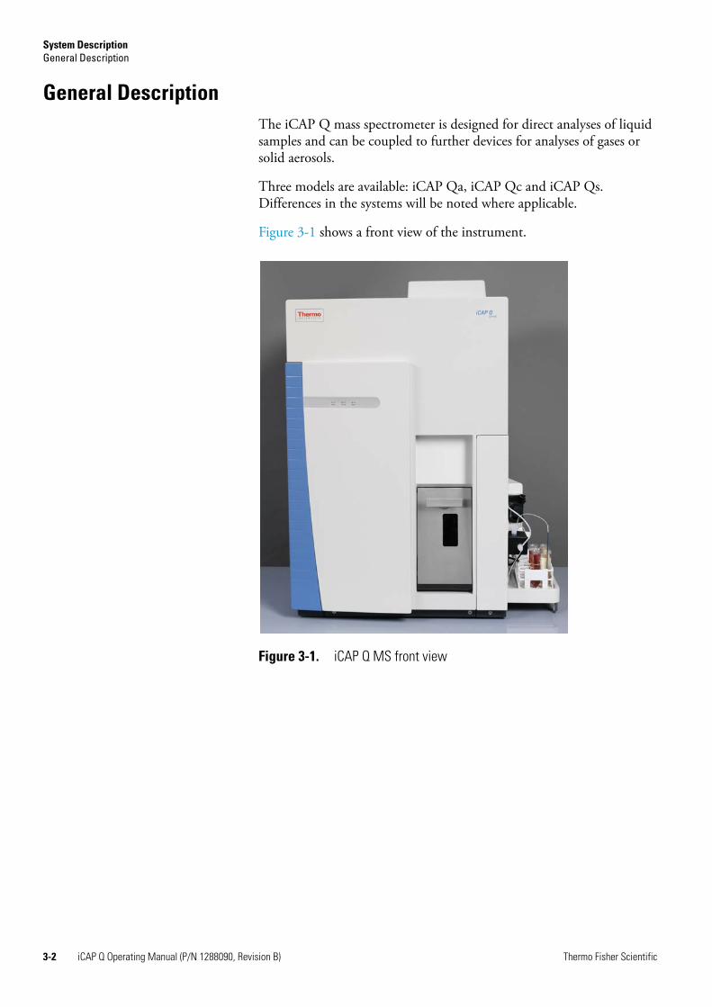
General DescriptionThe iCAP Q mass spectrometer is designed for direct analyses of liquid samples and can be coupled to further devices for analyses of gases or solid aerosols.
Three models are available: iCAP Qa, iCAP Qc and iCAP Qs. Differences in the systems will be noted where applicable.
Figure 3-1 shows a front view of the instrument.
Figure 3-1. iCAP Q MS front view
3-2 iCAP Q Operating Manual (P/N 1288090, Revision B) Thermo Fisher Scientific
System DescriptionGeneral Description
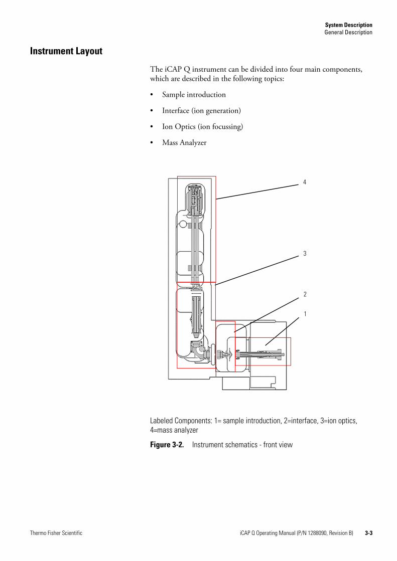
Instrument Layout
The iCAP Q instrument can be divided into four main components, which are described in the following topics:
• Sample introduction
• Interface (ion generation)
• Ion Optics (ion focussing)
• Mass Analyzer
Labeled Components: 1= sample introduction, 2=interface, 3=ion optics, 4=mass analyzer
Figure 3-2. Instrument schematics - front view
1
2
3
4
Thermo Fisher Scientific iCAP Q Operating Manual (P/N 1288090, Revision B) 3-3
System DescriptionSample Introduction System
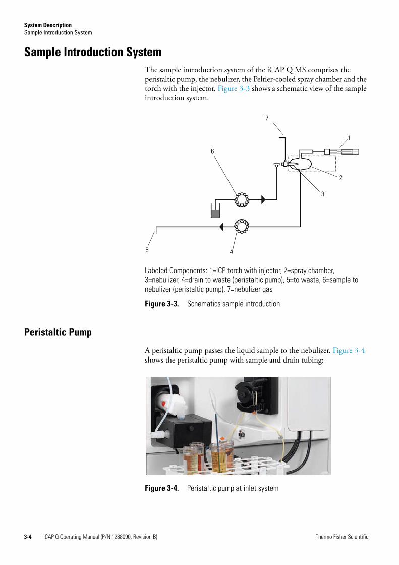
Sample Introduction SystemThe sample introduction system of the iCAP Q MS comprises the peristaltic pump, the nebulizer, the Peltier-cooled spray chamber and the torch with the injector. Figure 3-3 shows a schematic view of the sample introduction system.
Peristaltic Pump
A peristaltic pump passes the liquid sample to the nebulizer. Figure 3-4 shows the peristaltic pump with sample and drain tubing:
Labeled Components: 1=ICP torch with injector, 2=spray chamber, 3=nebulizer, 4=drain to waste (peristaltic pump), 5=to waste, 6=sample to nebulizer (peristaltic pump), 7=nebulizer gas
Figure 3-3. Schematics sample introduction
3
2
1
4
6
7
5
Figure 3-4. Peristaltic pump at inlet system
3-4 iCAP Q Operating Manual (P/N 1288090, Revision B) Thermo Fisher Scientific
System DescriptionSample Introduction System
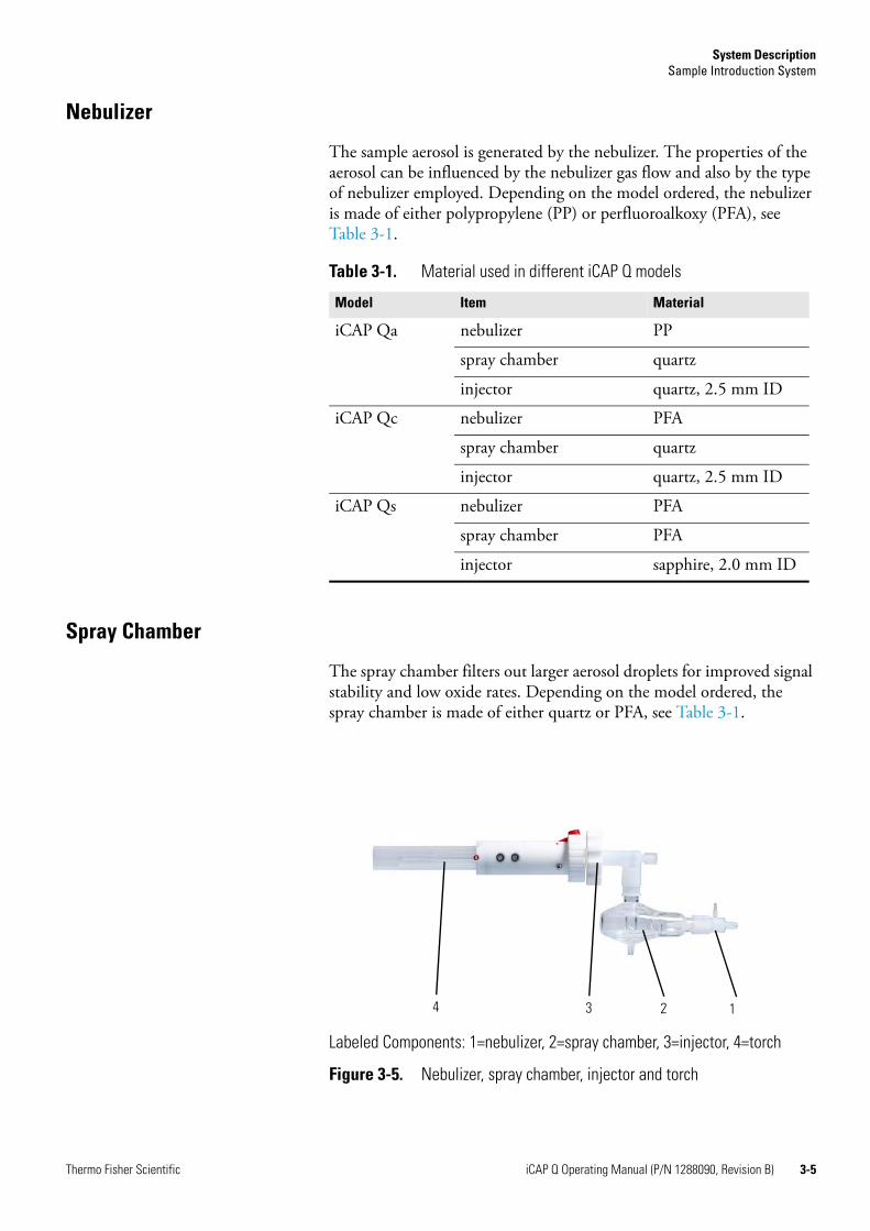
Nebulizer
The sample aerosol is generated by the nebulizer. The properties of the aerosol can be influenced by the nebulizer gas flow and also by the type of nebulizer employed. Depending on the model ordered, the nebulizer is made of either polypropylene (PP) or perfluoroalkoxy (PFA), see Table 3-1.
Spray Chamber
The spray chamber filters out larger aerosol droplets for improved signal stability and low oxide rates. Depending on the model ordered, the spray chamber is made of either quartz or PFA, see Table 3-1.
Table 3-1. Material used in different iCAP Q models
Model Item Material
iCAP Qa nebulizer PP
spray chamber quartz
injector quartz, 2.5 mm ID
iCAP Qc nebulizer PFA
spray chamber quartz
injector quartz, 2.5 mm ID
iCAP Qs nebulizer PFA
spray chamber PFA
injector sapphire, 2.0 mm ID
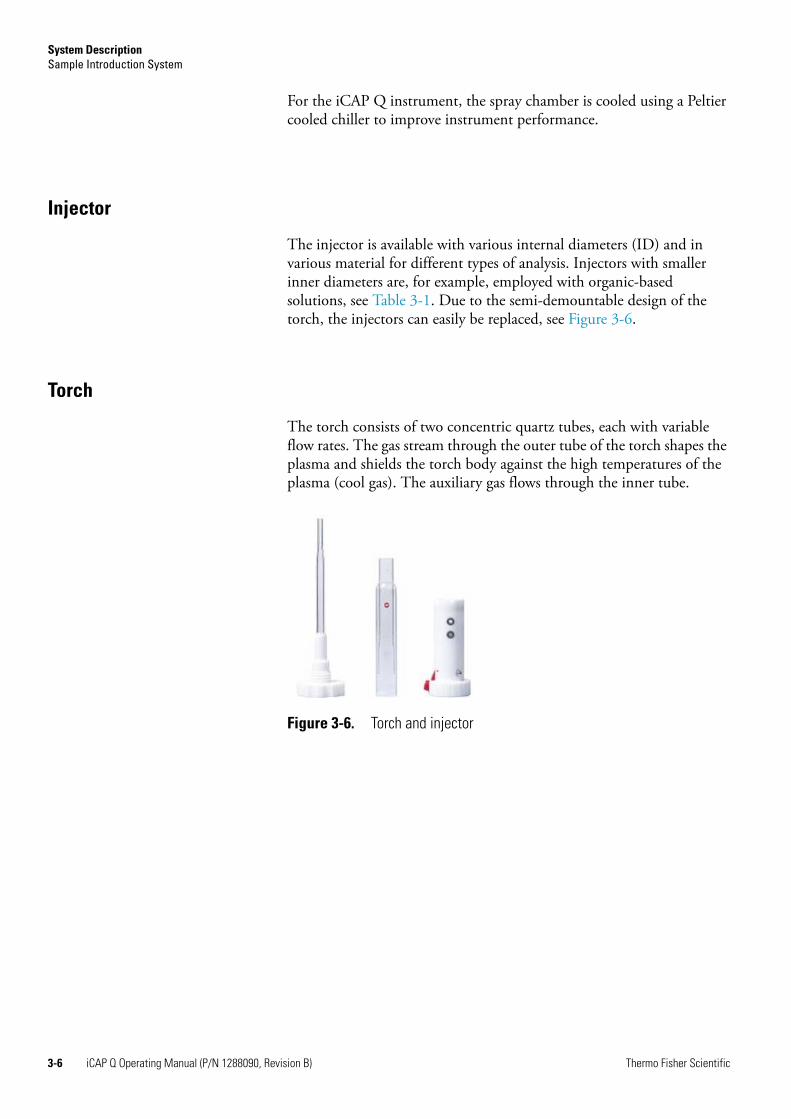
Labeled Components: 1=nebulizer, 2=spray chamber, 3=injector, 4=torch
Figure 3-5. Nebulizer, spray chamber, injector and torch
1234
Thermo Fisher Scientific iCAP Q Operating Manual (P/N 1288090, Revision B) 3-5
System DescriptionSample Introduction System
For the iCAP Q instrument, the spray chamber is cooled using a Peltier cooled chiller to improve instrument performance.
Injector
The injector is available with various internal diameters (ID) and in various material for different types of analysis. Injectors with smaller inner diameters are, for example, employed with organic-based solutions, see Table 3-1. Due to the semi-demountable design of the torch, the injectors can easily be replaced, see Figure 3-6.
Torch
The torch consists of two concentric quartz tubes, each with variable flow rates. The gas stream through the outer tube of the torch shapes the plasma and shields the torch body against the high temperatures of the plasma (cool gas). The auxiliary gas flows through the inner tube.
Figure 3-6. Torch and injector
3-6 iCAP Q Operating Manual (P/N 1288090, Revision B) Thermo Fisher Scientific
System DescriptionInterface
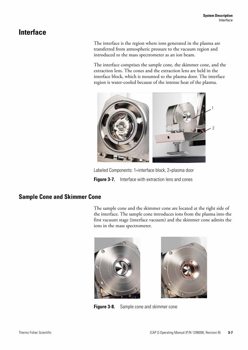
InterfaceThe interface is the region where ions generated in the plasma are transferred from atmospheric pressure to the vacuum region and introduced to the mass spectrometer as an ion beam.
The interface comprises the sample cone, the skimmer cone, and the extraction lens. The cones and the extraction lens are held in the interface block, which is mounted to the plasma door. The interface region is water-cooled because of the intense heat of the plasma.
Sample Cone and Skimmer Cone
The sample cone and the skimmer cone are located at the right side of the interface. The sample cone introduces ions from the plasma into the first vacuum stage (interface vacuum) and the skimmer cone admits the ions in the mass spectrometer.
Labeled Components: 1=interface block, 2=plasma door
Figure 3-7. Interface with extraction lens and cones
1
2
Figure 3-8. Sample cone and skimmer cone
Thermo Fisher Scientific iCAP Q Operating Manual (P/N 1288090, Revision B) 3-7
System DescriptionInterface
The skimmer cone is made of nickel and the sample cone is made of Ni/Cu. Pt-tipped cones are optionally available, for example, for analysis of organics or reactive acids like HF (hydrofluoric acid).
Extraction Lens
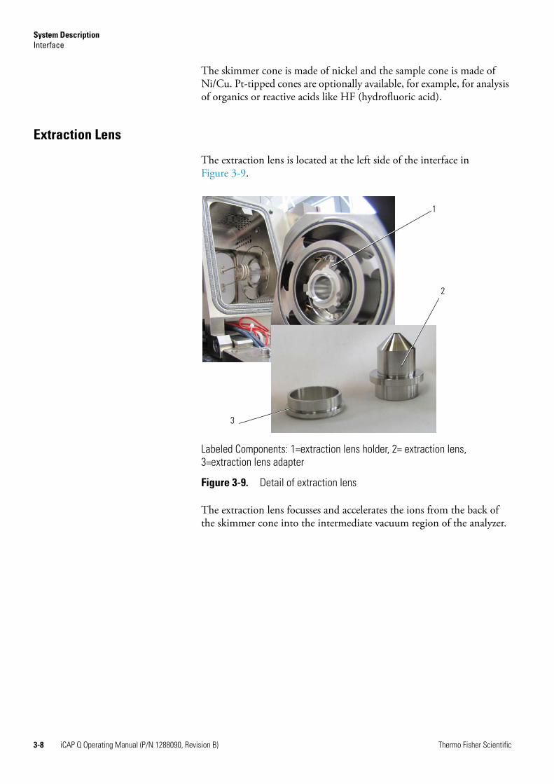
The extraction lens is located at the left side of the interface in Figure 3-9.
The extraction lens focusses and accelerates the ions from the back of the skimmer cone into the intermediate vacuum region of the analyzer.
Labeled Components: 1=extraction lens holder, 2= extraction lens, 3=extraction lens adapter
Figure 3-9. Detail of extraction lens
1
2
3
3-8 iCAP Q Operating Manual (P/N 1288090, Revision B) Thermo Fisher Scientific
System DescriptionIon Optics
Ion Optics The ion optics region comprises the RAPID lens, the QCell, and the DA assembly.
RAPID Lens
Ions extracted from the iCAP Q interface are accelerated to the RAPID (Right Angle Positive Ion Deflection) lens which deflects analyte ions by 90 ° before they enter the QCell.
The RAPID lens ensures that neutral particles from the plasma pass directly out of the lens without interacting with an active lens surface for improved reliability and reduced maintenance.
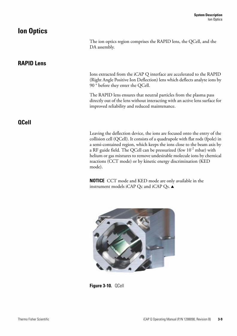
QCell
Leaving the deflection device, the ions are focused onto the entry of the collision cell (QCell). It consists of a quadrupole with flat rods (fpole) in a semi-contained region, which keeps the ions close to the beam axis by a RF guide field. The QCell can be pressurized (few 10-2 mbar) with helium or gas mixtures to remove undesirable molecule ions by chemical reactions (CCT mode) or by kinetic energy discrimination (KED mode).
NOTICE CCT mode and KED mode are only available in the instrument models iCAP Qc and iCAP Qs. ▲
Figure 3-10. QCell
Thermo Fisher Scientific iCAP Q Operating Manual (P/N 1288090, Revision B) 3-9
System DescriptionMass Analyzer
DA Assembly
From the QCell, the ion beam is focused onto a small differential aperture (DA plate), which separates the intermediate vacuum stage from the high vacuum analyzer region. Directly behind the DA plate, the beam is deflected again by the DA lens to remove residual (collision) gas particles from the ion beam.
Mass Analyzer
Quadrupole
The ions are then introduced into the quadrupole mass analyzer, which filters out ions of a specific mass to charge ratio, depending on the RF voltage and DC voltage applied to the quadrupole rods.
Detector
Ions transmitted through the quadrupole are finally transferred to the dual mode secondary electron multiplier (SEM) and detected.
3-10 iCAP Q Operating Manual (P/N 1288090, Revision B) Thermo Fisher Scientific
System DescriptionVacuum System
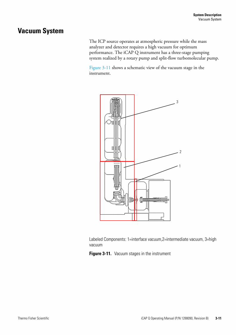
Vacuum SystemThe ICP source operates at atmospheric pressure while the mass analyzer and detector requires a high vacuum for optimum performance. The iCAP Q instrument has a three-stage pumping system realized by a rotary pump and split-flow turbomolecular pump.
Figure 3-11 shows a schematic view of the vacuum stage in the instrument.
Labeled Components: 1=interface vacuum,2=intermediate vacuum, 3=high vacuum
Figure 3-11. Vacuum stages in the instrument
1
3
2
Thermo Fisher Scientific iCAP Q Operating Manual (P/N 1288090, Revision B) 3-11
System DescriptionVacuum System
Forepump
The first vacuum region, the interface vacuum region between the sample cone and the skimmer cone, is pumped down by a rotary vane pump, the so-called forepump. The forepump is directly connected to the interface.
In addition to pumping down the interface region, the forepump also provides backing to the turbomolecular pump.
Turbomolecular Pump
The split-flow turbomolecular pump backed by the forepump pumps the intermediate stage and the high vacuum analyzer stage. The turbomolecular pump is located inside the instrument.
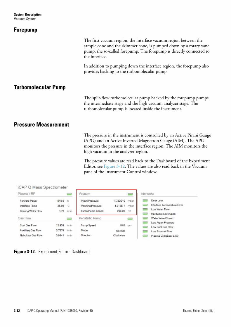
Pressure Measurement
The pressure in the instrument is controlled by an Active Pirani Gauge (APG) and an Active Inverted Magnetron Gauge (AIM). The APG monitors the pressure in the interface region. The AIM monitors the high vacuum in the analyzer region.
The pressure values are read back to the Dashboard of the Experiment Editor, see Figure 3-12. The values are also read back in the Vacuum pane of the Instrument Control window.
Figure 3-12. Experiment Editor - Dashboard
3-12 iCAP Q Operating Manual (P/N 1288090, Revision B) Thermo Fisher Scientific
System DescriptionGas Supply
Gas SupplyThe iCAP Q MS uses argon gas to generate the inductively coupled plasma and to control internal functions with the aid of pneumatics. Additional gases may be required depending on the type of analysis.
Also see “Permitted Materials” on page 4-7 for more information.
Connections
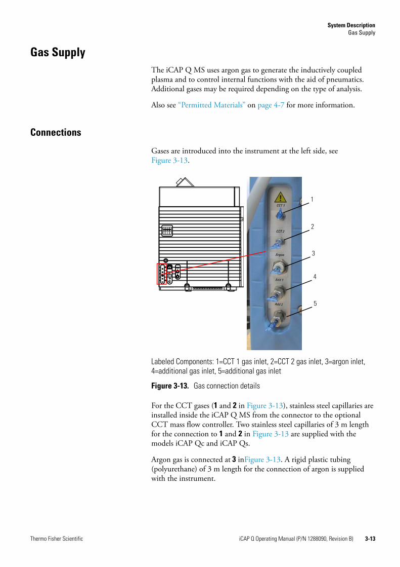
Gases are introduced into the instrument at the left side, see Figure 3-13.
For the CCT gases (1 and 2 in Figure 3-13), stainless steel capillaries are installed inside the iCAP Q MS from the connector to the optional CCT mass flow controller. Two stainless steel capillaries of 3 m length for the connection to 1 and 2 in Figure 3-13 are supplied with the models iCAP Qc and iCAP Qs.
Argon gas is connected at 3 inFigure 3-13. A rigid plastic tubing (polyurethane) of 3 m length for the connection of argon is supplied with the instrument.
Labeled Components: 1=CCT 1 gas inlet, 2=CCT 2 gas inlet, 3=argon inlet, 4=additional gas inlet, 5=additional gas inlet
Figure 3-13. Gas connection details
1
2
3
4
5
Thermo Fisher Scientific iCAP Q Operating Manual (P/N 1288090, Revision B) 3-13
System DescriptionGas Supply
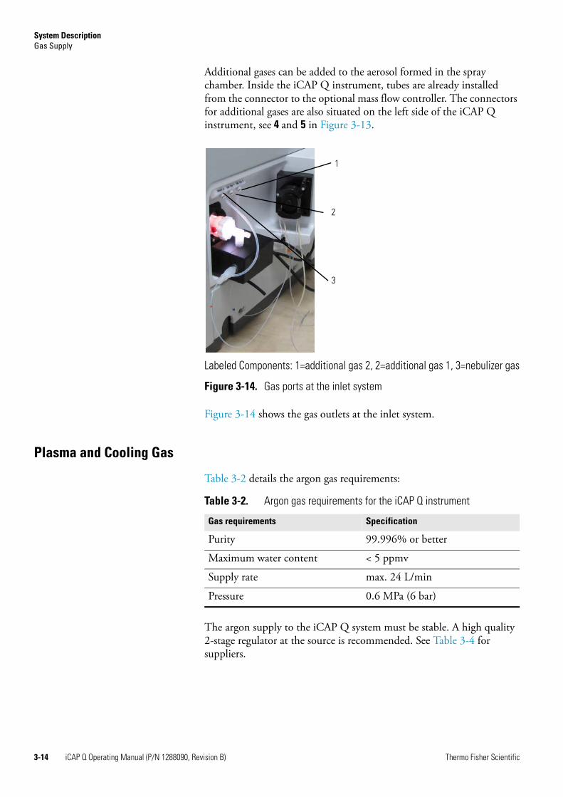
Additional gases can be added to the aerosol formed in the spray chamber. Inside the iCAP Q instrument, tubes are already installed from the connector to the optional mass flow controller. The connectors for additional gases are also situated on the left side of the iCAP Q instrument, see 4 and 5 in Figure 3-13.
Figure 3-14 shows the gas outlets at the inlet system.
Plasma and Cooling Gas
Table 3-2 details the argon gas requirements:
The argon supply to the iCAP Q system must be stable. A high quality 2-stage regulator at the source is recommended. See Table 3-4 for suppliers.
Labeled Components: 1=additional gas 2, 2=additional gas 1, 3=nebulizer gas
Figure 3-14. Gas ports at the inlet system
3
2
1
Table 3-2. Argon gas requirements for the iCAP Q instrument
Gas requirements Specification
Purity 99.996% or better
Maximum water content < 5 ppmv
Supply rate max. 24 L/min
Pressure 0.6 MPa (6 bar)
3-14 iCAP Q Operating Manual (P/N 1288090, Revision B) Thermo Fisher Scientific
System DescriptionGas Supply
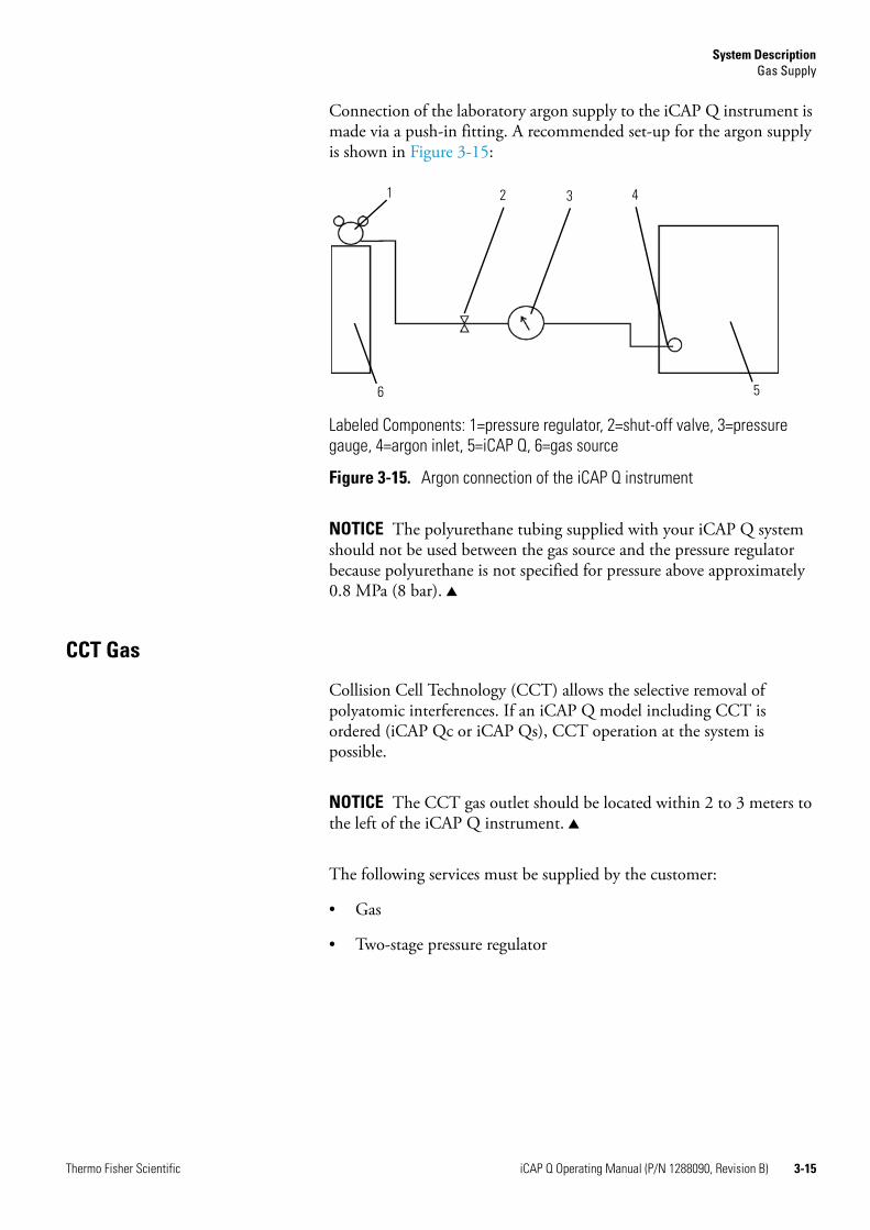
Connection of the laboratory argon supply to the iCAP Q instrument is made via a push-in fitting. A recommended set-up for the argon supply is shown in Figure 3-15:
NOTICE The polyurethane tubing supplied with your iCAP Q system should not be used between the gas source and the pressure regulator because polyurethane is not specified for pressure above approximately 0.8 MPa (8 bar). ▲
CCT Gas
Collision Cell Technology (CCT) allows the selective removal of polyatomic interferences. If an iCAP Q model including CCT is ordered (iCAP Qc or iCAP Qs), CCT operation at the system is possible.
NOTICE The CCT gas outlet should be located within 2 to 3 meters to the left of the iCAP Q instrument. ▲
The following services must be supplied by the customer:
• Gas
• Two-stage pressure regulator
Labeled Components: 1=pressure regulator, 2=shut-off valve, 3=pressure gauge, 4=argon inlet, 5=iCAP Q, 6=gas source
Figure 3-15. Argon connection of the iCAP Q instrument
1 2 3 4
56
Thermo Fisher Scientific iCAP Q Operating Manual (P/N 1288090, Revision B) 3-15
System DescriptionGas Supply
Helium
For the iCAP Qc and the iCAP Qs, an installation test is performed with helium gas to pressurize the CCT cell. See Table 3-3 for details of the helium gas requirements:
Two-stage Gas Pressure Regulator
The quality of the gas regulator is critical to ensure optimum performance. A high quality two-stage pressure regulator is absolutely essential.The plasma gas regulator should have a specification of 20 MPa (200 bar) primary pressure and 1 MPa (10 bar) outlet pressure. The CCT gas regulator should have a specification of 20 MPa (200 bar) primary pressure and 0.3 MPa (3 bar) outlet pressure.
Each country has a different standard outlet fitting for its gas supplies and therefore each country will require a different regulator. Examples for regulators are given by region in Table 3-4.1 If your region is not listed, contact your local Thermo Fisher Scientific service office for advice.
Thermo Fisher Scientific supplies the 1/16-inch to 1/4-inch adapter for the iCAP Qc and the iCAP Qs instruments to connect the CCT gas tubing to the gas bottle regulator. If the outlet from your regulator is not 1/4 inch, you will need to provide a suitable adapter.
Table 3-3. CCT gas requirements for helium
Gas requirements Specification
Purity 99.999% or better
Maximum water content 2 ppmv
Supply rate max. 10 mL/min
Pressure 0.1 MPa (1 bar)
1 Thermo Fisher Scientific does not endorse any manufacturer, nor does it endorse products other than its own. Companies and products listed in this guide are given as examples only.
Table 3-4. Regulator suppliers
Country Manufacturer Reference Code Gas Application
Europe Linde C 106/2 Plasma
Linde C 202/2 CCT
Linde C 200hv/2 CCT
Spectrolab LM62 Plasma
US Matheson 3810-CGA580 CCT
BOC HP1700 (CGA580)
CCT
3-16 iCAP Q Operating Manual (P/N 1288090, Revision B) Thermo Fisher Scientific
System DescriptionGas Supply
Additional Gas
Depending on the application, a variety of additional gases may be employed. The use of mass flow controllers is required when working with additional gases.
Oxygen
For the analysis of organic solvents the use of oxygen may be required. The gas requirements are detailed in Table 3-5.
NOTICE Temperature down to -10 °C will be required for the analysis of organic solvents. This is controlled via the Peltier cooler. ▲
Helium
For laser ablation analysis, helium gas may be needed. The gas requirements are detailed in Table 3-6.
Table 3-5. Additional gas requirements for oxygen
Gas Requirements Specification
Purity 99.996%
Maximum water content < 5 ppmv
Supply rate max. 1 L/min
Pressure regulator output 0.6 MPa (6 bar)
Table 3-6. Additional gas requirements for helium
Gas Requirements Specification
Purity 99.996%
Maximum water content < 5 ppmv
Supply rate max. 1 L/min
Pressure regulator output 0.6 MPa (6 bar)
Thermo Fisher Scientific iCAP Q Operating Manual (P/N 1288090, Revision B) 3-17
System DescriptionGas Supply
Argon
For some applications, the use of additional argon gas is beneficial. The gas requirements are detailed in Table 3-7.
Table 3-7. Additional gas requirements for argon
Gas Requirements Specification
Purity 99.996%
Maximum water content < 5 ppmv
Supply rate max. 1 L/min
Pressure regulator output 0.6 MPa (6 bar)
3-18 iCAP Q Operating Manual (P/N 1288090, Revision B) Thermo Fisher Scientific
System DescriptionCooling System
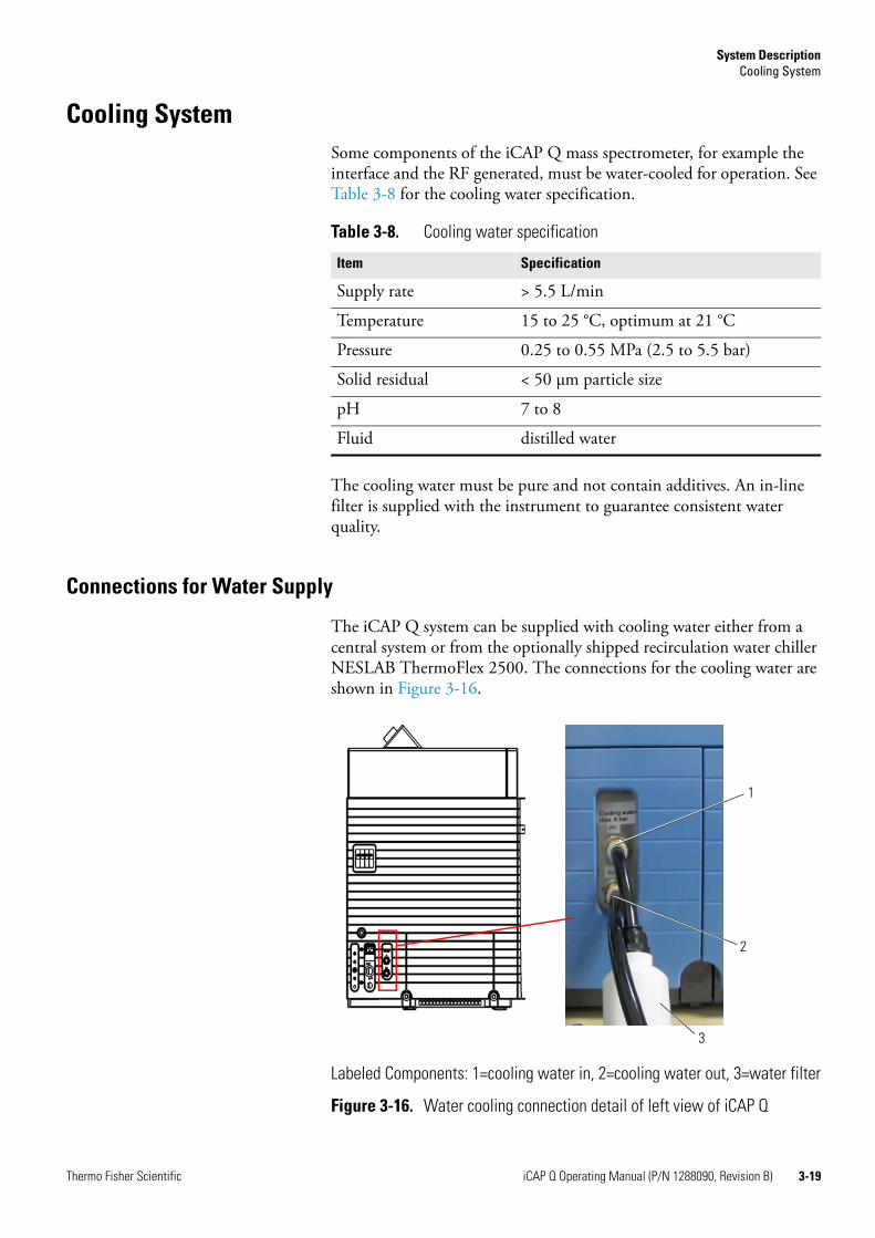
Cooling SystemSome components of the iCAP Q mass spectrometer, for example the interface and the RF generated, must be water-cooled for operation. See Table 3-8 for the cooling water specification.
The cooling water must be pure and not contain additives. An in-line filter is supplied with the instrument to guarantee consistent water quality.
Connections for Water Supply
The iCAP Q system can be supplied with cooling water either from a central system or from the optionally shipped recirculation water chiller NESLAB ThermoFlex 2500. The connections for the cooling water are shown in Figure 3-16.
Table 3-8. Cooling water specification
Item Specification
Supply rate > 5.5 L/min
Temperature 15 to 25 °C, optimum at 21 °C
Pressure 0.25 to 0.55 MPa (2.5 to 5.5 bar)
Solid residual < 50 μm particle size
pH 7 to 8
Fluid distilled water
Labeled Components: 1=cooling water in, 2=cooling water out, 3=water filter
Figure 3-16. Water cooling connection detail of left view of iCAP Q
1
2
3
Thermo Fisher Scientific iCAP Q Operating Manual (P/N 1288090, Revision B) 3-19
System DescriptionCooling System
Recirculating Chiller
Optionally, the iCAP Q mass spectrometer is delivered with the recirculating chiller NESLAB ThermoFlex 2500 with closed circuit, cooled by a refrigerating device.
NOTICE For more information, refer to the manufacturer’s manual supplied with the instrument and see “Recirculating Chiller” on page 9-4. ▲
3-20 iCAP Q Operating Manual (P/N 1288090, Revision B) Thermo Fisher Scientific
System DescriptionExhaust System
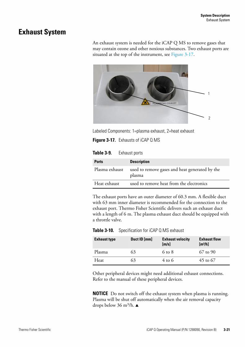
Exhaust SystemAn exhaust system is needed for the iCAP Q MS to remove gases that may contain ozone and other noxious substances. Two exhaust ports are situated at the top of the instrument, see Figure 3-17.
The exhaust ports have an outer diameter of 60.3 mm. A flexible duct with 63 mm inner diameter is recommended for the connection to the exhaust port. Thermo Fisher Scientific delivers such an exhaust duct with a length of 6 m. The plasma exhaust duct should be equipped with a throttle valve.
Other peripheral devices might need additional exhaust connections. Refer to the manual of these peripheral devices.
NOTICE Do not switch off the exhaust system when plasma is running. Plasma will be shut off automatically when the air removal capacity drops below 36 m³/h. ▲
Labeled Components: 1=plasma exhaust, 2=heat exhaust
Figure 3-17. Exhausts of iCAP Q MS
Table 3-9. Exhaust ports
Ports Description
Plasma exhaust used to remove gases and heat generated by the plasma
Heat exhaust used to remove heat from the electronics
Table 3-10. Specification for iCAP Q MS exhaust
Exhaust type Duct ID [mm] Exhaust velocity [m/s]
Exhaust flow [m³/h]
Plasma 63 6 to 8 67 to 90
Heat 63 4 to 6 45 to 67
2
1
Thermo Fisher Scientific iCAP Q Operating Manual (P/N 1288090, Revision B) 3-21
System DescriptionConnections
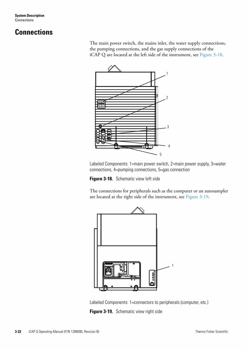
ConnectionsThe main power switch, the mains inlet, the water supply connections, the pumping connections, and the gas supply connections of the iCAP Q are located at the left side of the instrument, see Figure 3-18.
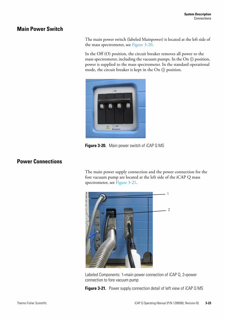
The connections for peripherals such as the computer or an autosamplerare located at the right side of the instrument, see Figure 3-19.
Labeled Components: 1=main power switch, 2=main power supply, 3=water connections, 4=pumping connections, 5=gas connection
Figure 3-18. Schematic view left side
Labeled Components: 1=connectors to peripherals (computer, etc.)
Figure 3-19. Schematic view right side
1
2
5
4
3
1
3-22 iCAP Q Operating Manual (P/N 1288090, Revision B) Thermo Fisher Scientific
System DescriptionConnections
Main Power Switch
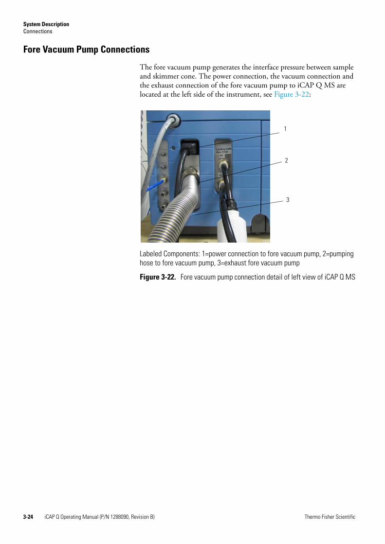
The main power switch (labeled Mainpower) is located at the left side of the mass spectrometer, see Figure 3-20.
In the Off (O) position, the circuit breaker removes all power to the mass spectrometer, including the vacuum pumps. In the On (|) position, power is supplied to the mass spectrometer. In the standard operational mode, the circuit breaker is kept in the On (|) position.
Power Connections
The main power supply connection and the power connection for the fore vacuum pump are located at the left side of the iCAP Q mass spectrometer, see Figure 3-21.
Figure 3-20. Main power switch of iCAP Q MS
Labeled Components: 1=main power connection of iCAP Q, 2=power connection to fore vacuum pump
Figure 3-21. Power supply connection detail of left view of iCAP Q MS
1
2
Thermo Fisher Scientific iCAP Q Operating Manual (P/N 1288090, Revision B) 3-23
System DescriptionConnections
Fore Vacuum Pump Connections
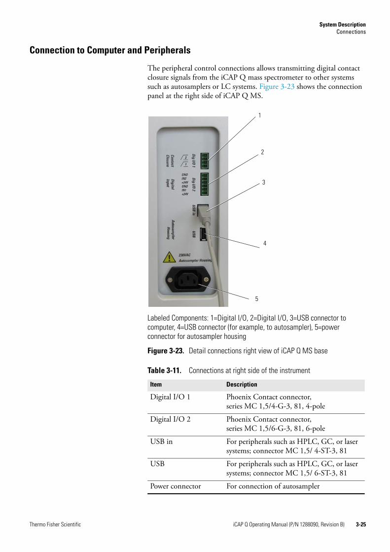
The fore vacuum pump generates the interface pressure between sample and skimmer cone. The power connection, the vacuum connection and the exhaust connection of the fore vacuum pump to iCAP Q MS are located at the left side of the instrument, see Figure 3-22:
Labeled Components: 1=power connection to fore vacuum pump, 2=pumping hose to fore vacuum pump, 3=exhaust fore vacuum pump
Figure 3-22. Fore vacuum pump connection detail of left view of iCAP Q MS
1
2
3
3-24 iCAP Q Operating Manual (P/N 1288090, Revision B) Thermo Fisher Scientific
System DescriptionConnections
Connection to Computer and Peripherals
The peripheral control connections allows transmitting digital contact closure signals from the iCAP Q mass spectrometer to other systems such as autosamplers or LC systems. Figure 3-23 shows the connection panel at the right side of iCAP Q MS.
Labeled Components: 1=Digital I/O, 2=Digital I/O, 3=USB connector to computer, 4=USB connector (for example, to autosampler), 5=power connector for autosampler housing
Figure 3-23. Detail connections right view of iCAP Q MS base
Table 3-11. Connections at right side of the instrument
Item Description
Digital I/O 1 Phoenix Contact connector, series MC 1,5/4-G-3, 81, 4-pole
Digital I/O 2 Phoenix Contact connector,series MC 1,5/6-G-3, 81, 6-pole
USB in For peripherals such as HPLC, GC, or laser systems; connector MC 1,5/ 4-ST-3, 81
USB For peripherals such as HPLC, GC, or laser systems; connector MC 1,5/ 6-ST-3, 81
Power connector For connection of autosampler
1
2
4
5
3
Thermo Fisher Scientific iCAP Q Operating Manual (P/N 1288090, Revision B) 3-25

System DescriptionConnections
3-26 iCAP Q Operating Manual (P/N 1288090, Revision B) Thermo Fisher Scientific
Chapter 4 Safety
This chapter summarizes important safety instructions for properly using your system. This chapter contains the following topics:
• “Safety Symbols and Signal Words in this Manual” on page 4-2
• “Safety Symbols on the Instrument” on page 4-3
• “Rating Plate” on page 4-5
• “Intended Use” on page 4-6
• “Permitted Materials” on page 4-7
• “Electrical Safety Precautions” on page 4-8
• “Residual Hazards” on page 4-9
• “Personal Protective Equipment” on page 4-10
• “EMC Information” on page 4-11
• “In Case of Emergency” on page 4-12
Thermo Fisher Scientific iCAP Q Operating Manual (P/N 1288090, Revision B) 4-1
SafetySafety Symbols and Signal Words in this Manual
Safety Symbols and Signal Words in this ManualMake sure to follow the precautionary statements presented in this manual. The safety notices are indicated in the following way:
Observing this Manual
This manual must always be kept near the instrument to be available for quick reference.
System configuration and specifications in this manual supersede all previous information received by the purchaser.
! Indicates the use and effect of safety instructions.
CAUTION! Indicates unsafe situations that can cause mild injury or bodily harm.
WARNING!Indicates unsafe situations that can cause moderately severe injury or bodily harm.
DANGER! Indicates unsafe situations that can cause severe injury or bodily harm or death.
! Be sure to read and comply with all precautions described in this manual.
4-2 iCAP Q Operating Manual (P/N 1288090, Revision B) Thermo Fisher Scientific
SafetySafety Symbols on the Instrument
Safety Symbols on the InstrumentTable 4-1 lists all safety labels on the instrument and their respective position. See the safety notices to prevent risk of harm to the operator and to protect the instrument against damage. If present, read and follow the instructions on the labels.
Table 4-1. Safety labels on the instrument
Label Label description Label position
The label indicates the presence of UV radiation (category 2) in the plasma.
The total averaged and weighted UV irradiance in 100 mm measuring distance is: 1.53 x 10⁻³ W/m².
The label indicates an in-running nip point hazard at the peristaltic pump.
The label indicates the presence of electricity at the main power switch.
The label indicates the presence of high voltage inside the instrument.
Thermo Fisher Scientific iCAP Q Operating Manual (P/N 1288090, Revision B) 4-3
SafetySafety Symbols on the Instrument
The label indicates the presence of UV radiation (category 1) inside the instrument.
The total averaged and weighted UV irradiance in 100 mm measuring distance is: 0.27 x 10⁻³ W/m².
The label indicates the presence of noxious gases at the plasma exhaust.
The label marks the gas connections. Only permitted gases may be connected here, see “Permitted Materials” on page 4-7.
Table 4-1. Safety labels on the instrument
Label Label description Label position
4-4 iCAP Q Operating Manual (P/N 1288090, Revision B) Thermo Fisher Scientific
SafetyRating Plate
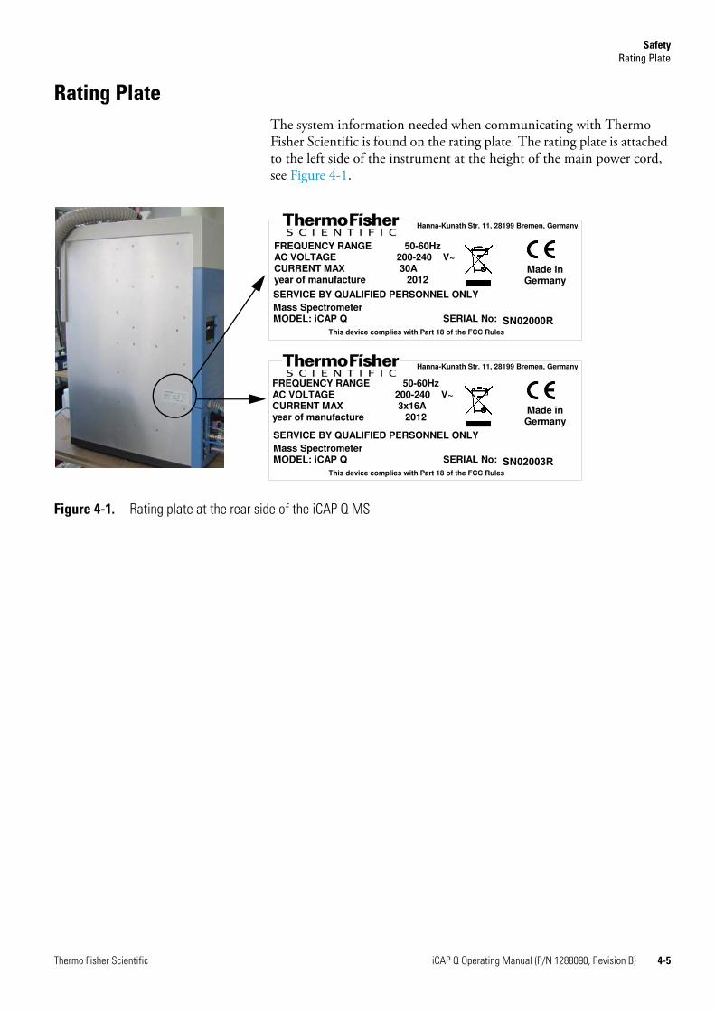
Rating PlateThe system information needed when communicating with Thermo Fisher Scientific is found on the rating plate. The rating plate is attached to the left side of the instrument at the height of the main power cord, see Figure 4-1.
Figure 4-1. Rating plate at the rear side of the iCAP Q MS
SERVICE BY QUALIFIED PERSONNEL ONLY
FREQUENCY RANGE 50-60Hz AC VOLTAGE 200-240 V~CURRENT MAX 3x16A year of manufacture 2012
Mass SpectrometerMODEL: iCAP Q SERIAL No: ��������
Made in Germany
Hanna-Kunath Str. 11, 28199 Bremen, Germany
This device complies with Part 18 of the FCC Rules
SERVICE BY QUALIFIED PERSONNEL ONLY
FREQUENCY RANGE 50-60Hz AC VOLTAGE 200-240 V~CURRENT MAX 30A year of manufacture 2012
Mass SpectrometerMODEL: iCAP Q SERIAL No: ��������
Made in Germany
Hanna-Kunath Str. 11, 28199 Bremen, Germany
This device complies with Part 18 of the FCC Rules
Thermo Fisher Scientific iCAP Q Operating Manual (P/N 1288090, Revision B) 4-5
SafetyIntended Use
Intended UseThe iCAP Q ICP-MS is a bench top instrument designed for mass spectrometric analyses of liquid samples, gases and aerosols, which are led into the instrument, for example, directly or via peristaltic pumps.
! Observe the following usage guidelines when you operate your iCAP Q mass spectrometer:
• The instrument is designed to be placed on a bench in the laboratory. It is not designed for the use outdoors.
• The instrument is designed for laboratory research use only. It is not designed for use in diagnostic or medical therapeutic procedures.
If the iCAP Q mass spectrometer is used in a manner not specified by Thermo Fisher Scientific, the protection provided by the instrument could be impaired. Thermo Fisher Scientific assumes no responsibility and will not be liable for instrument damage and/or operator injury.Whenever the safety protection of the mass spectrometer has been compromised, disconnect the instrument from all power sources and secure the unit against unintended operation.
4-6 iCAP Q Operating Manual (P/N 1288090, Revision B) Thermo Fisher Scientific
SafetyPermitted Materials
Qualified Personnel
Permitted MaterialsThe iCAP Q mass spectrometer is designed to be operated with the following materials:
• Argon: Used to maintain the ICP, and to actuate pneumatic controls
• Helium: Used for the removal of polyatomic interferences
• Oxygen: Used for analysis of organic matrices
• Helium/Hydrogen Mixed Gas (7% Hydrogen/93% Helium)
• Fore vacuum pump oil: Used for cooling, lubrication, and sealing of the fore vacuum pump
• Calibration compounds, samples
• Organic solvents like isopropanol
NOTICE Do not use pure hydrogen with the iCAP Q instrument. ▲
! Only employees of Thermo Fisher Scientific or personnel acting on behalf of Thermo Fisher Scientific are permitted to install the iCAP Q mass spectrometer.Personnel that installs or operates iCAP Q mass spectrometer must have the following qualifications:
• Electrical Connections
The electrical installation must be carried out by qualified and trained personnel (electrician) according to the appropriate regulations (for example, cable cross-sections, fuses, PE connection).
• General Operation
The iCAP Q mass spectrometer is designed to be operated by qualified laboratory personnel. Before starting, all users must be instructed about the hazards presented by the instrument and the used chemicals. The users must be advised to read the relevant Material Safety Data Sheets (MSDSs).
Thermo Fisher Scientific iCAP Q Operating Manual (P/N 1288090, Revision B) 4-7

SafetyElectrical Safety Precautions
Electrical Safety Precautions
WARNING!High Voltage. High voltages capable of causing an electric shock are used in the instrument.Observe the following safety precautions when you operate or perform service on your instrument:
• Do not change the external or internal grounding connections.Tampering with or disconnecting these connections could endanger you and/or damage the system.
• The instrument is properly grounded in accordance with regulations when shipped. You do not need to make any changes to the electrical connections or to the instrument’s chassis to ensure safe operation.
• Never run the system without the housing on. Permanent damage can occur. When leaving the system, make sure that all protective covers and doors are properly connected and closed, and that heated areas are separated and marked to protect unqualified personnel.
• Do not turn the instrument on if you suspect that it has incurred any kind of electrical damage. Instead, disconnect the power cords of mass spectrometer and forepump and contact a Thermo Fisher Scientific field service engineer for a product evaluation. Do not attempt to use the instrument until it has been evaluated. Electrical damage may have occurred if the system shows visible signs of damage, or has been transported under severe stress.
• Do not place any objects upon the instrument—especially not containers with liquids—unless it is requested by the user documentation. Leaking liquids might get into contact with electronic components and cause a short circuit.
4-8 iCAP Q Operating Manual (P/N 1288090, Revision B) Thermo Fisher Scientific
SafetyResidual Hazards
Residual HazardsWhere risks remain despite the inherent safe design measures, safeguarding and complementary protective measures adopted, the necessary warnings, including warning devices, must be provided.
The iCAP Q mass spectrometer is engineered to minimize machine components and operating procedures that may compromise operator safety. To maintain some machine operations and functionality, certain compromises are required. The following safety notices document some of these residual hazards. By making the operator aware of the potential risks, we hope to ensure maximum safety in the operation of this mass spectrometer.
Users of the iCAP Q mass spectrometer must pay attention to the following residual hazards.
WARNING!Toxic Gases. Danger of intoxication. Toxic gases are released that may lead to severe bodily harm when the spray chamber is disassembled. Do not disassemble the spray chamber when the plasma is still on.
CAUTION! Hazardous Chemical. Samples and solvents might contain toxic, carcinogenic, mutagenic, or corrosive/irritant chemicals. Avoid exposure to potentially harmful materials. Always wear protective clothing, gloves, and safety glasses when you handle solvents or samples. Also contain waste streams and use proper ventilation. Refer to your supplier's Material Safety Data Sheet (MSDS) for proper handling of a particular compound.
CAUTION! Burn Hazard. Fore vacuum pump in operation is hot and some surfaces could reach a temperature higher than 80 °C (176 °F). Switch off the pump and let it cool down before any intervention or take appropriate precautions. All work on a pump that is “still warm from operation” should be done only while wearing heat protective gloves.
CAUTION! Hazardous Gases. Danger to health. When operating the instrument with hazardous gas, an external warning sensor must be installed in the vicinity of the instrument.
CAUTION! Hot Surface. Danger of burns. Switch off the plasma at least 2 minutes before handling the torch or cones.
Thermo Fisher Scientific iCAP Q Operating Manual (P/N 1288090, Revision B) 4-9
SafetyPersonal Protective Equipment
Personal Protective EquipmentAppropriate safety clothing must be worn at all times while operating the mass spectrometer, particularly when handling hazardous materials.
This manual can only give general suggestions for personal protective equipment (PPE), which protects the wearer from hazardous substances. Refer to the Material Safety Data Sheets (MSDSs) of the chemicals handled in your laboratory for advice on specific hazards or additional equipment.
Eye Protection
The type of eye protection required depends on the hazard. For most situations, safety glasses with side shields are adequate. Where there is a risk of splashing chemicals, goggles are required.
Protective Clothing
When the possibility of chemical contamination exists, protective clothing that resists physical and chemical hazards should be worn over street clothes. Lab coats are appropriate for minor chemical splashes and solids contamination, while plastic or rubber aprons are best for protection from corrosive or irritating liquids.
Gloves
For handling chemical compounds and organic solvents, Thermo Fisher Scientific recommends the following gloves: white nitrile clean room gloves (Fisher Scientific P/N 19-120-2947B [size medium] or P/N 19-120-2947C [size large]; Thermo Scientific P/N 23827-0008) [size medium] or P/N 23827-0009 [size large]).
For handling hot objects, gloves made of heat-resistant materials (for example, leather) should be available.
CAUTION! UV Radiation. Eye and skin hazard. UV radiation is released when the spray chamber is disassembled. UV radiation may lead to severe eye injury or blindness. Protect eyes and skin from exposure to UV light. Do not disassemble the spray chamber when the plasma is still on.
CAUTION! Hot Gases. Danger of severe burns. Hot gases are released that may lead to severe burns when the spray chamber is disassembled. Do not disassemble the spray chamber when the plasma is still on.
4-10 iCAP Q Operating Manual (P/N 1288090, Revision B) Thermo Fisher Scientific
SafetyEMC Information
EMC InformationIn accordance with our commitment to customer service and safety, this instrument has satisfied the requirements for the European CE Mark including the Low Voltage Directive.
Designed, manufactured and tested in an ISO9001 registered facility, this instrument has been shipped to you from our manufacturing facility in a safe condition.
This instrument must be used as described in this manual. Any use of this instrument in a manner other than described here may result in instrument damage and/or operator injury.
Notice on the Susceptibility to Electromagnetic Transmissions
Your instrument is designed to work in a controlled electromagnetic environment. Do not use radio frequency transmitters, such as mobile phones, in close proximity to the instrument.
Thermo Fisher Scientific iCAP Q Operating Manual (P/N 1288090, Revision B) 4-11
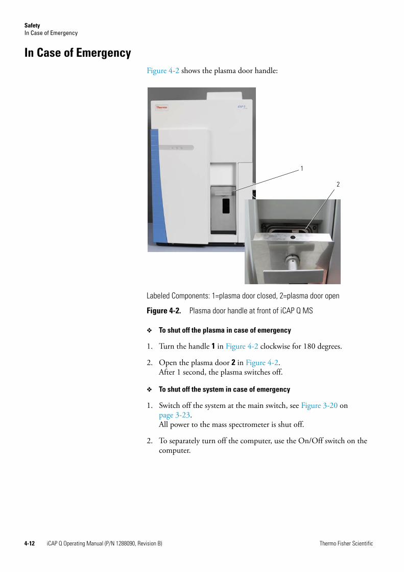
SafetyIn Case of Emergency
In Case of EmergencyFigure 4-2 shows the plasma door handle:
❖ To shut off the plasma in case of emergency
1. Turn the handle 1 in Figure 4-2 clockwise for 180 degrees.
2. Open the plasma door 2 in Figure 4-2.After 1 second, the plasma switches off.
❖ To shut off the system in case of emergency
1. Switch off the system at the main switch, see Figure 3-20 on page 3-23.All power to the mass spectrometer is shut off.
2. To separately turn off the computer, use the On/Off switch on the computer.
Labeled Components: 1=plasma door closed, 2=plasma door open
Figure 4-2. Plasma door handle at front of iCAP Q MS
1
2
4-12 iCAP Q Operating Manual (P/N 1288090, Revision B) Thermo Fisher Scientific
Chapter 5 System Setup
This chapter describes the conditions for an operating environment that will ensure continued high performance of your iCAP Q system. It contains the following sections:
• “Safety Guidelines for Installation” on page 5-2
• “Placing the System” on page 5-3
• “Laboratory Conditions” on page 5-7
! Only employees of Thermo Fisher Scientific or personnel acting on behalf of Thermo Fisher Scientific are allowed to install the iCAP Q mass spectrometer.Only employees of Thermo Fisher Scientific or personnel acting on behalf of Thermo Fisher Scientific are allowed to install the additional gas module (MFC).
Thermo Fisher Scientific iCAP Q Operating Manual (P/N 1288090, Revision B) 5-1

System SetupSafety Guidelines for Installation
Safety Guidelines for InstallationNote the following general safety guidelines for the installation of the iCAP Q mass spectrometer.
WARNING!Noxious Gases. Danger to health. Hazardous materials might be present in the effluent of the fore vacuum pump. Be sure to connect to an adequate exhaust system.
CAUTION! Hazardous Gases. Danger to health. When operating the instrument with hazardous gas, an external warning sensor must be installed in the vicinity of the instrument.
5-2 iCAP Q Operating Manual (P/N 1288090, Revision B) Thermo Fisher Scientific
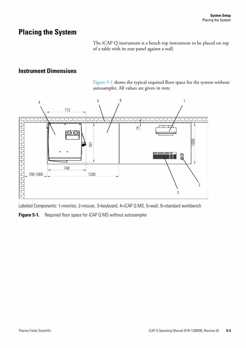
System SetupPlacing the System
Placing the SystemThe iCAP Q instrument is a bench top instrument to be placed on top of a table with its rear panel against a wall.
Instrument Dimensions
Figure 5-1 shows the typical required floor space for the system without autosampler. All values are given in mm:
Labeled Components: 1=monitor, 2=mouse, 3=keyboard, 4=iCAP Q MS, 5=wall, 6=standard workbench
Figure 5-1. Required floor space for iCAP Q MS without autosampler
700-1000 1200748
772
767
15
1000
4 5 6 1
2
3
Thermo Fisher Scientific iCAP Q Operating Manual (P/N 1288090, Revision B) 5-3
System SetupPlacing the System
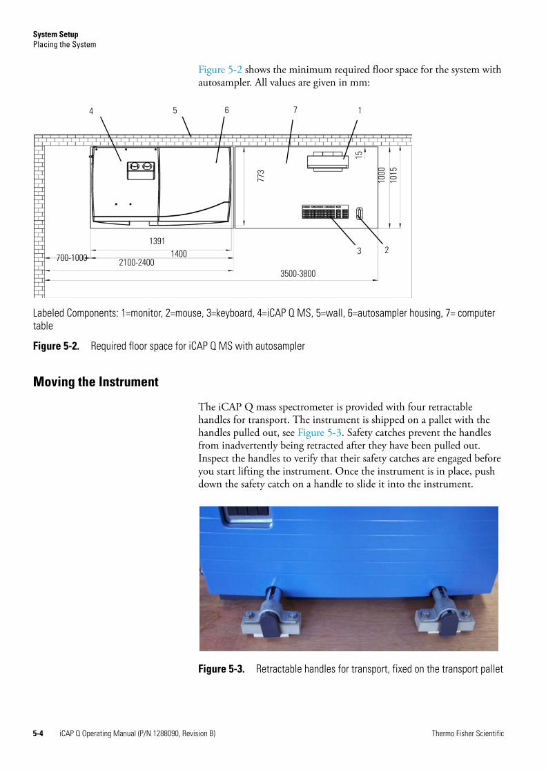
Figure 5-2 shows the minimum required floor space for the system with autosampler. All values are given in mm:
Moving the Instrument
The iCAP Q mass spectrometer is provided with four retractable handles for transport. The instrument is shipped on a pallet with the handles pulled out, see Figure 5-3. Safety catches prevent the handles from inadvertently being retracted after they have been pulled out. Inspect the handles to verify that their safety catches are engaged before you start lifting the instrument. Once the instrument is in place, push down the safety catch on a handle to slide it into the instrument.
Labeled Components: 1=monitor, 2=mouse, 3=keyboard, 4=iCAP Q MS, 5=wall, 6=autosampler housing, 7= computer table
Figure 5-2. Required floor space for iCAP Q MS with autosampler
700-1000 14001391
2100-24003500-3800
1000
15
4 5 6 7 1
2377
3
1015
Figure 5-3. Retractable handles for transport, fixed on the transport pallet
5-4 iCAP Q Operating Manual (P/N 1288090, Revision B) Thermo Fisher Scientific
System SetupPlacing the System
Moving the Forepump
For easy and effortless transportation of the forevacuum pump, Thermo Fisher Scientific provides a mobile base (drip pan with casters) with the iCAP Q mass spectrometer.
If lifting of the forevacuum pump becomes necessary, only a suitable lifting device shall be used to lift the pump at the lifting lug due to the forevacuum pump weight of about 43 kg.
Should people lift the pump, at least two persons should lift it. Pay attention to the persons' position when lifting! Straight back, flexed knees, and adapted back large belts, etc. are recommended.
When moving the forepump, pay attention to the following guidelines:
• 1 person stands on the left side, one hand under the oil casing and one hand under the pump stator.
• 1 person stands on the right side, one hand under the oil casing and one hand under the motor fan cover.
• Attention to your hands when setting down the pump into the drip pan to avoid squashing!
NOTICE Do not lift the pump at the frequency converter or the cables! ▲
Workbench for Instrument
The workbench for the MS system must be capable of supporting the weight of the mass spectrometer(148 kg) plus the weight of any option (autosampler, liquid chromatograph, for example) and stand in a secure and level position.
CAUTION! Heavy Instrument. Danger of injury. This instrument is too heavy for one person alone to handle safely. Lifting and moving the instrument requires the effort of at least four persons. Thermo Fisher Scientific recommends using a pallet jack to lift the mass spectrometer onto the workbench.
! A lifting device is the only officially recommended way of handling the pump!
! Only workbenches with four legs provide sufficient stability for the iCAP Q mass spectrometer. The workbench must be dry and clean.
Thermo Fisher Scientific iCAP Q Operating Manual (P/N 1288090, Revision B) 5-5
System SetupPlacing the System
Minimum Clearance
Allow at least 70 to 100 cm of clear space left of the system for proper air circulation and for clearance of the gas lines, electrical connections, and exhaust lines and vacuum hose of the fore vacuum pump.
On the left side panel, free access to the mains switch and circuit breaker is needed to allow shutting off the instrument in case of an emergency at all times.
It is recommended to leave sufficient space on the right side of the iCAP Q system for the connections to the computer and peripheral devices.
NOTICE Avoid blocking the ventilation slots at the side of the instrument. Items may fall behind the instrument, inhibit airflow, and cause the system to overheat. ▲
5-6 iCAP Q Operating Manual (P/N 1288090, Revision B) Thermo Fisher Scientific
System SetupLaboratory Conditions
Laboratory ConditionsThis section gives an overview of important requirements for the laboratory where the iCAP Q mass spectrometer is placed. For details, refer to the iCAP Q Preinstallation Requirements Guide.
Power Supply
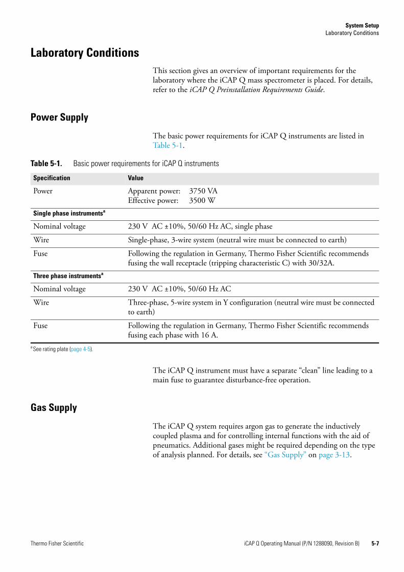
The basic power requirements for iCAP Q instruments are listed in Table 5-1.
The iCAP Q instrument must have a separate “clean” line leading to a main fuse to guarantee disturbance-free operation.
Gas Supply
The iCAP Q system requires argon gas to generate the inductively coupled plasma and for controlling internal functions with the aid of pneumatics. Additional gases might be required depending on the type of analysis planned. For details, see “Gas Supply” on page 3-13.
Table 5-1. Basic power requirements for iCAP Q instruments
Specification Value
Power Apparent power: 3750 VAEffective power: 3500 W
Single phase instrumentsa
Nominal voltage 230 V AC ±10%, 50/60 Hz AC, single phase
Wire Single-phase, 3-wire system (neutral wire must be connected to earth)
Fuse Following the regulation in Germany, Thermo Fisher Scientific recommends fusing the wall receptacle (tripping characteristic C) with 30/32A.
Three phase instrumentsa
Nominal voltage 230 V AC ±10%, 50/60 Hz AC
Wire Three-phase, 5-wire system in Y configuration (neutral wire must be connected to earth)
Fuse Following the regulation in Germany, Thermo Fisher Scientific recommends fusing each phase with 16 A.
a See rating plate (page 4-5).
Thermo Fisher Scientific iCAP Q Operating Manual (P/N 1288090, Revision B) 5-7
System SetupLaboratory Conditions
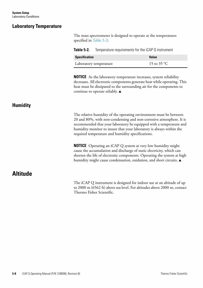
Laboratory Temperature
The mass spectrometer is designed to operate at the temperatures specified in Table 5-2:
NOTICE As the laboratory temperature increases, system reliability decreases. All electronic components generate heat while operating. This heat must be dissipated to the surrounding air for the components to continue to operate reliably. ▲
Humidity
The relative humidity of the operating environment must be between 20 and 80%, with non-condensing and non-corrosive atmosphere. It is recommended that your laboratory be equipped with a temperature and humidity monitor to insure that your laboratory is always within the required temperature and humidity specifications.
NOTICE Operating an iCAP Q system at very low humidity might cause the accumulation and discharge of static electricity, which can shorten the life of electronic components. Operating the system at high humidity might cause condensation, oxidation, and short circuits. ▲
AltitudeThe iCAP Q instrument is designed for indoor use at an altitude of up to 2000 m (6562 ft) above sea level. For altitudes above 2000 m, contact Thermo Fisher Scientific.
Table 5-2. Temperature requirements for the iCAP Q instrument
Specification Value
Laboratory temperature 15 to 35 °C
5-8 iCAP Q Operating Manual (P/N 1288090, Revision B) Thermo Fisher Scientific
System SetupLaboratory Conditions
Ventilation and Fume Exhaust
Heat generation and heat dissipation of the system depend on the equipment employed. However, the iCAP Q system must always be operated with active plasma exhaust. For a description of the exhaust system, see “Exhaust System” on page 3-21.
Vibration
Floors must be free of vibration caused, for example, by equipment in adjoining locations.
NOTICE The fore vacuum pump must not have any mechanical contact to the mass spectrometer with exception of the vacuum hose during operation. The vibration of the fore vacuum pump might impede the performance of the instrument. Install the fore vacuum pump on the floor beneath the mass spectrometer. Do not install the fore vacuum pump near the system on the workbench. ▲
Airborne Noise Emission
The mean value for the emission sound pressure level of the iCAP Q instrument is below 70 dB.
CAUTION! Hazardous Chemical. Samples and solvents might contain toxic, carcinogenic, mutagenic, or corrosive/irritant chemicals. Avoid exposure to potentially harmful materials. Always wear protective clothing, gloves, and safety glasses when you handle solvents or samples. Also contain waste streams and use proper ventilation. Refer to your supplier's Material Safety Data Sheet (MSDS) for proper handling of a particular compound.
Thermo Fisher Scientific iCAP Q Operating Manual (P/N 1288090, Revision B) 5-9

System SetupLaboratory Conditions
5-10 iCAP Q Operating Manual (P/N 1288090, Revision B) Thermo Fisher Scientific
Chapter 6 Operation
This chapter outlines the basic system operations and checks before operation. It contains the following sections:
• “Safety Guidelines for Operation” on page 6-2
• “System Controls” on page 6-4
• “Starting Up the System” on page 6-6
• “Shutting Down the System” on page 6-7
• “Getting Ready” on page 6-9
• “Working with LabBooks” on page 6-14
• “After Operation” on page 6-16
Thermo Fisher Scientific iCAP Q Operating Manual (P/N 1288090, Revision B) 6-1
OperationSafety Guidelines for Operation
Safety Guidelines for OperationWhen operating the iCAP Q system, please pay attention to the following general safety guidelines.
WARNING!Toxic Gases. Danger of intoxication. Toxic gases are released that might lead to severe bodily harm when the plasma exhaust is not connected to an exhaust system or the spray chamber is disassembled. Do not disassemble the spray chamber when the plasma is still on.
CAUTION! Hazardous Chemical. Samples and solvents might contain toxic, carcinogenic, mutagenic, or corrosive/irritant chemicals. Avoid exposure to potentially harmful materials. Always wear protective clothing, gloves, and safety glasses when you handle solvents or samples. Also contain waste streams and use proper ventilation. Refer to your supplier's Material Safety Data Sheet (MSDS) for proper handling of a particular compound.
CAUTION! Burn Hazard. Fore vacuum pump in operation is hot and some surfaces could reach a temperature higher than 80 °C (176 °F). Switch off the pump and let it cool down before any intervention or take appropriate precautions. All work on a pump that is “still warm from operation” should be done only while wearing heat protective gloves.
CAUTION! Hot Surface. Danger of burns. Switch off the plasma two minutes before handling the torch or cones.
CAUTION! Hazardous Gases. Danger to health. When operating the instrument with hazardous gas, an external warning sensor must be installed in the vicinity of the instrument.
CAUTION! UV Radiation. Danger of severe bodily harm. UV radiation is released when the spray chamber is disassembled. UV radiation might lead to severe eye injury or blindness. Do not disassemble the spray chamber when the plasma is still on. Keep a minimum distance of 20 cm when looking in the plasma. Do not operate the system when the plasma door window is damaged.
CAUTION! Hot Gases. Danger of severe burns. Hot gases are released that might lead to severe burns when the spray chamber is disassembled. Do not disassemble the spray chamber when the plasma is still on.
6-2 iCAP Q Operating Manual (P/N 1288090, Revision B) Thermo Fisher Scientific

OperationSafety Guidelines for Operation
CAUTION! Cold surface. Danger of frostbite. In normal operation and directly after operation the Peltier chiller may be cold. Do not touch the Peltier chiller in normal operation and directly after operation.
CAUTION! Pinch Point Hazard. Danger of injuries. Keep hands clear from the peristaltic pump during operation.
CAUTION! Rotating Parts Hazard. Danger of injuries. The peristaltic pump rollers can pull in hair, clothing, ties and other loose objects. Stay clear from the peristaltic pump during operation.
Thermo Fisher Scientific iCAP Q Operating Manual (P/N 1288090, Revision B) 6-3
OperationSystem Controls
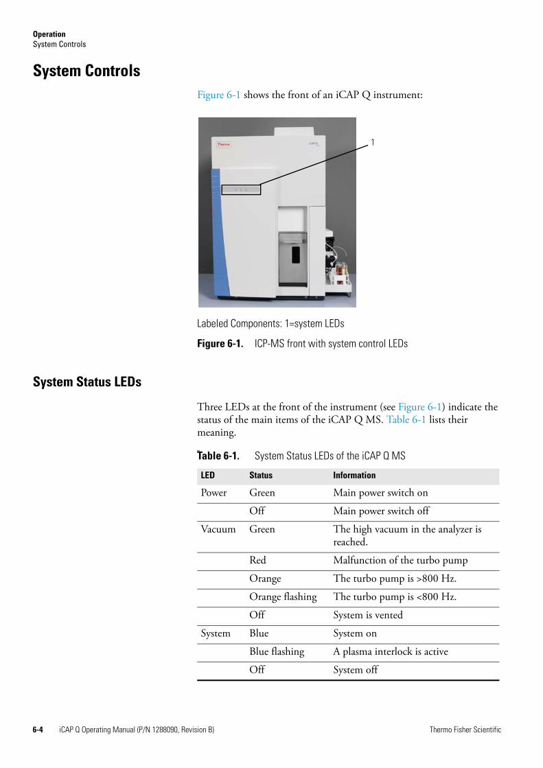
System ControlsFigure 6-1 shows the front of an iCAP Q instrument:
System Status LEDs
Three LEDs at the front of the instrument (see Figure 6-1) indicate the status of the main items of the iCAP Q MS. Table 6-1 lists their meaning.MS:
Labeled Components: 1=system LEDs
Figure 6-1. ICP-MS front with system control LEDs
1
Table 6-1. System Status LEDs of the iCAP Q MS
LED Status Information
Power Green Main power switch on
Off Main power switch off
Vacuum Green The high vacuum in the analyzer is reached.
Red Malfunction of the turbo pump
Orange The turbo pump is >800 Hz.
Orange flashing The turbo pump is <800 Hz.
Off System is vented
System Blue System on
Blue flashing A plasma interlock is active
Off System off
6-4 iCAP Q Operating Manual (P/N 1288090, Revision B) Thermo Fisher Scientific
OperationSystem Controls
NOTICE The system status LEDs give a quick overview of the general system status; they do not have any function for the safety status of the instrument. Before performing any maintenance on the instrument, make sure that the main power switch is in the OFF position and that the power cords of mass spectrometer and forepump are disconnected. It is not sufficient that the Power LED is off because it might be defective. ▲
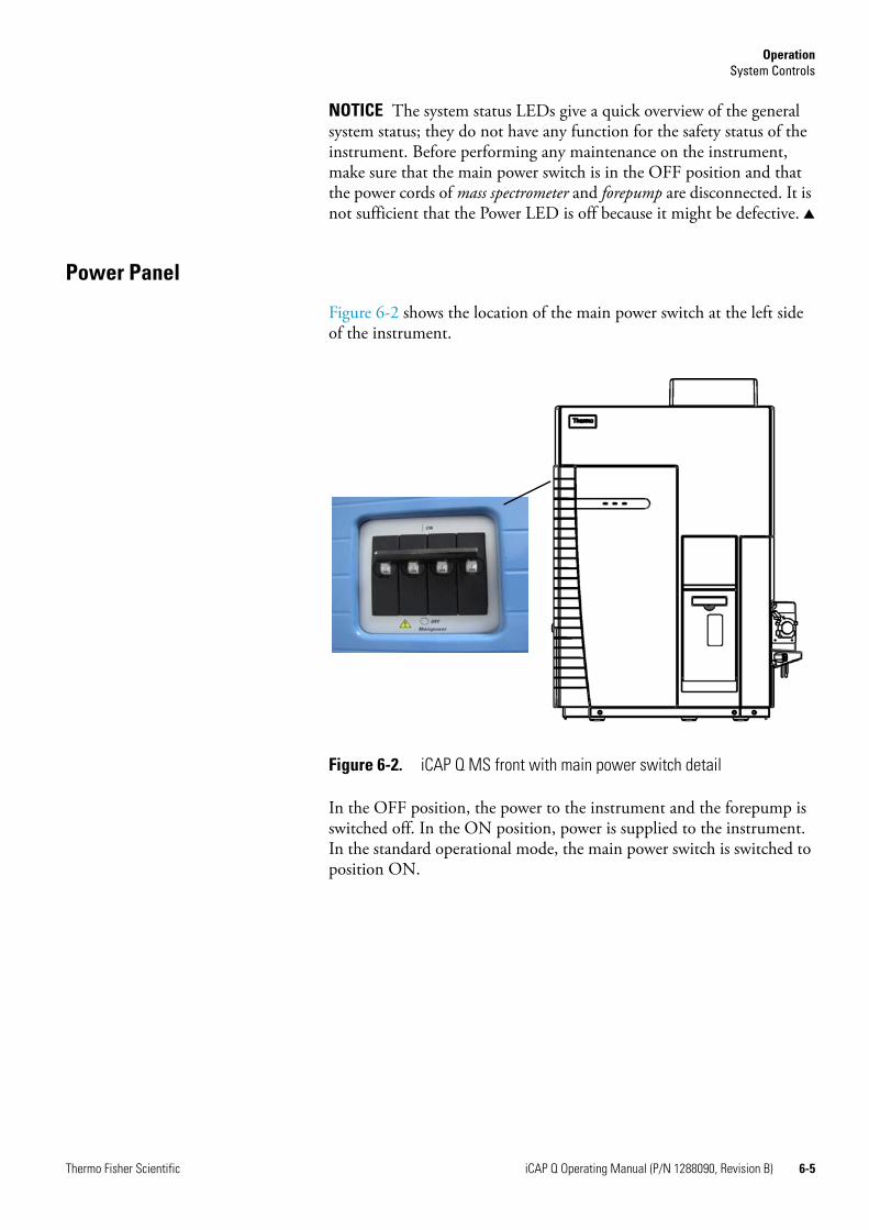
Power Panel
Figure 6-2 shows the location of the main power switch at the left side of the instrument.
In the OFF position, the power to the instrument and the forepump is switched off. In the ON position, power is supplied to the instrument. In the standard operational mode, the main power switch is switched to position ON.
Figure 6-2. iCAP Q MS front with main power switch detail
Thermo Fisher Scientific iCAP Q Operating Manual (P/N 1288090, Revision B) 6-5
OperationStarting Up the System
Starting Up the SystemAfter the system was shut down, the following procedure should be executed to start the system again.
Initial position:
• The system is switched off.
• The system is vented.
❖ To start the instrument
1. Switch the main power switch to position On, see Figure 6-2.
2. Start the vacuum system in the Instrument Control window
a. Click in the Vacuum submenu.
b. Wait for the turbomolecular pump to reach at least a frequency of 800 Hz.
3. Check the vacuum. The vacuum pressure is correct when the vacuum LED is green, see Figure 6-1.
4. If the system was vented, the detector should be calibrated regardless of whether it was changed or not.
The Get Ready procedure can now be started, see “Getting Ready” on page 6-9.
6-6 iCAP Q Operating Manual (P/N 1288090, Revision B) Thermo Fisher Scientific
OperationShutting Down the System
Shutting Down the SystemShutting down the system is only necessary for maintenance reasons.
Switching to Standby Mode
After the experiments are finished and the system was flushed, in the evening or before weekends, the instrument can be set to standby position.
Initial position:
• The experiments are finished.
• The plasma is still lit.
• The system was flushed.
❖ To set the instrument to standby
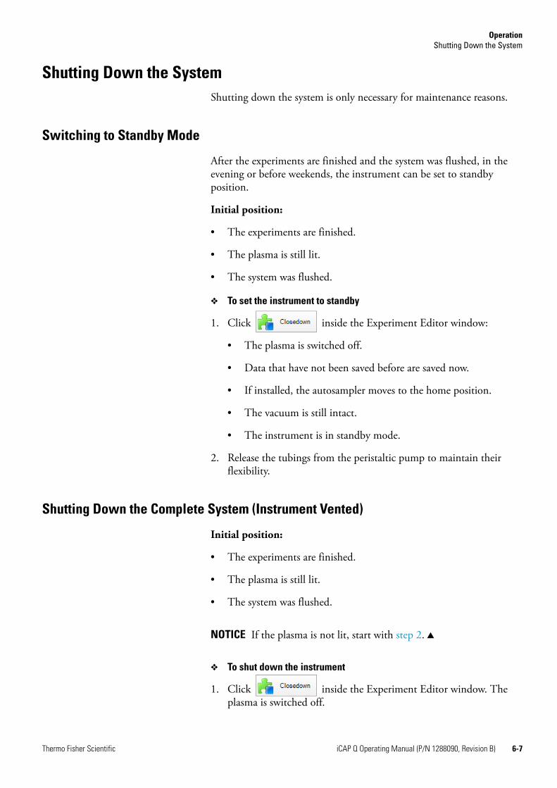
1. Click inside the Experiment Editor window:
• The plasma is switched off.
• Data that have not been saved before are saved now.
• If installed, the autosampler moves to the home position.
• The vacuum is still intact.
• The instrument is in standby mode.
2. Release the tubings from the peristaltic pump to maintain their flexibility.
Shutting Down the Complete System (Instrument Vented)
Initial position:
• The experiments are finished.
• The plasma is still lit.
• The system was flushed.
NOTICE If the plasma is not lit, start with step 2. ▲
❖ To shut down the instrument
1. Click inside the Experiment Editor window. The plasma is switched off.
Thermo Fisher Scientific iCAP Q Operating Manual (P/N 1288090, Revision B) 6-7
OperationShutting Down the System
2. Switch off the vacuum system in the Instrument Control window
a. Click in the Vacuum submenu
Wait until the system is fully vented.
3. Switch the main power switch to position Off, see Figure 6-2.
Shutting Down the Instrument only (Instrument not Vented)
Initial position:
• The experiments are finished.
• The plasma is still lit.
• The system was flushed.
NOTICE If the plasma is not lit, start with step 2. ▲
❖ To shut down the instrument
1. Click inside the Experiment Editor window. The plasma is switched off.
2. Switch the main power switch to Off position.
6-8 iCAP Q Operating Manual (P/N 1288090, Revision B) Thermo Fisher Scientific
OperationGetting Ready
Getting Ready Thermo Fisher Scientific provides a tool to easily start up the iCAP Q mass spectrometer. An automatic sequence can be started that switches on the plasma and will carry out a routine check of the instrument’s performance by generating a performance report. All measurement modes that have been previously defined by the user will be set up. In case that the performance of the instrument does not match the requirements from the performance report, an autotune sequence or mass calibration will be automatically be triggered to fix the problems. Afterwards, a second performance report is generated.
The measurement modes settings STD, KED and CCT for samples containing matrix load are provided by Thermo Fisher Scientific. Additionally, the modes STDS, KEDS and CCTS are provided for optimized sensitivity for samples without matrix load. The Lab Manager may create company-specific measurement modes.
Before Operating the System
Before operating the system, it is recommended to check the tubings of the peristaltic pump.
❖ To check the pump tubings
1. Make sure that the tubings of the peristaltic pump are not damaged or clogged.
2. Make sure that the tubings of the peristaltic pump are secured with the collars and brackets.
NOTICE If the sample to be analyzed contains a high percentage of organic solvent, the pump tubing should be replaced with solvent-resistant pump tubing. ▲
Getting Ready with the Experiment Editor
❖ To start the system
1. Open the Experiment Editor. As a default, the Dashboard page appears.
The Dashboard gives a complete overview about the iCAP Q mass spectrometer and all installed peripherals.
Thermo Fisher Scientific iCAP Q Operating Manual (P/N 1288090, Revision B) 6-9
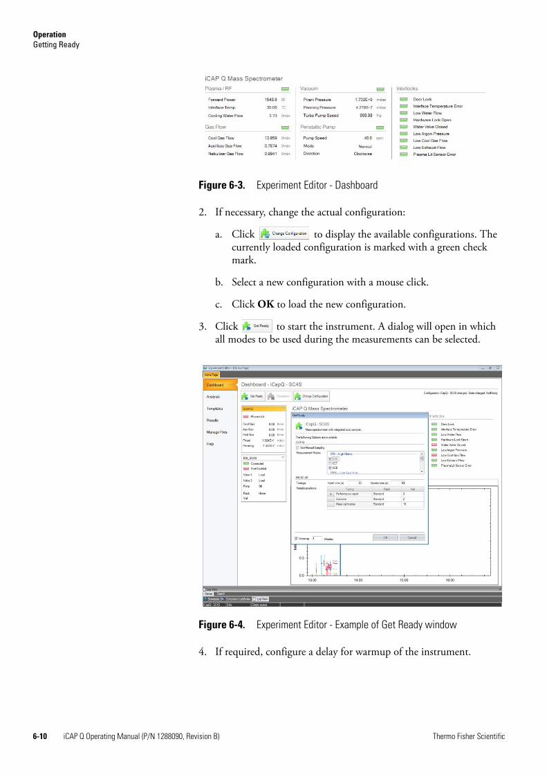
OperationGetting Ready
2. If necessary, change the actual configuration:
a. Click to display the available configurations. The currently loaded configuration is marked with a green check mark.
b. Select a new configuration with a mouse click.
c. Click OK to load the new configuration.
3. Click to start the instrument. A dialog will open in which all modes to be used during the measurements can be selected.
4. If required, configure a delay for warmup of the instrument.
Figure 6-3. Experiment Editor - Dashboard
Figure 6-4. Experiment Editor - Example of Get Ready window
6-10 iCAP Q Operating Manual (P/N 1288090, Revision B) Thermo Fisher Scientific
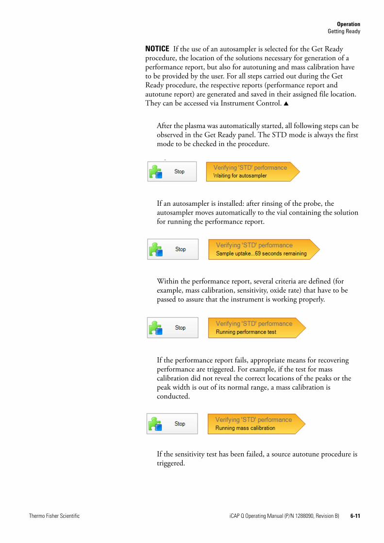
OperationGetting Ready
NOTICE If the use of an autosampler is selected for the Get Ready procedure, the location of the solutions necessary for generation of a performance report, but also for autotuning and mass calibration have to be provided by the user. For all steps carried out during the Get Ready procedure, the respective reports (performance report and autotune report) are generated and saved in their assigned file location. They can be accessed via Instrument Control. ▲
After the plasma was automatically started, all following steps can be observed in the Get Ready panel. The STD mode is always the first mode to be checked in the procedure.
If an autosampler is installed: after rinsing of the probe, the autosampler moves automatically to the vial containing the solution for running the performance report.
Within the performance report, several criteria are defined (for example, mass calibration, sensitivity, oxide rate) that have to be passed to assure that the instrument is working properly.
If the performance report fails, appropriate means for recovering performance are triggered. For example, if the test for mass calibration did not reveal the correct locations of the peaks or the peak width is out of its normal range, a mass calibration is conducted.
If the sensitivity test has been failed, a source autotune procedure is triggered.
Thermo Fisher Scientific iCAP Q Operating Manual (P/N 1288090, Revision B) 6-11
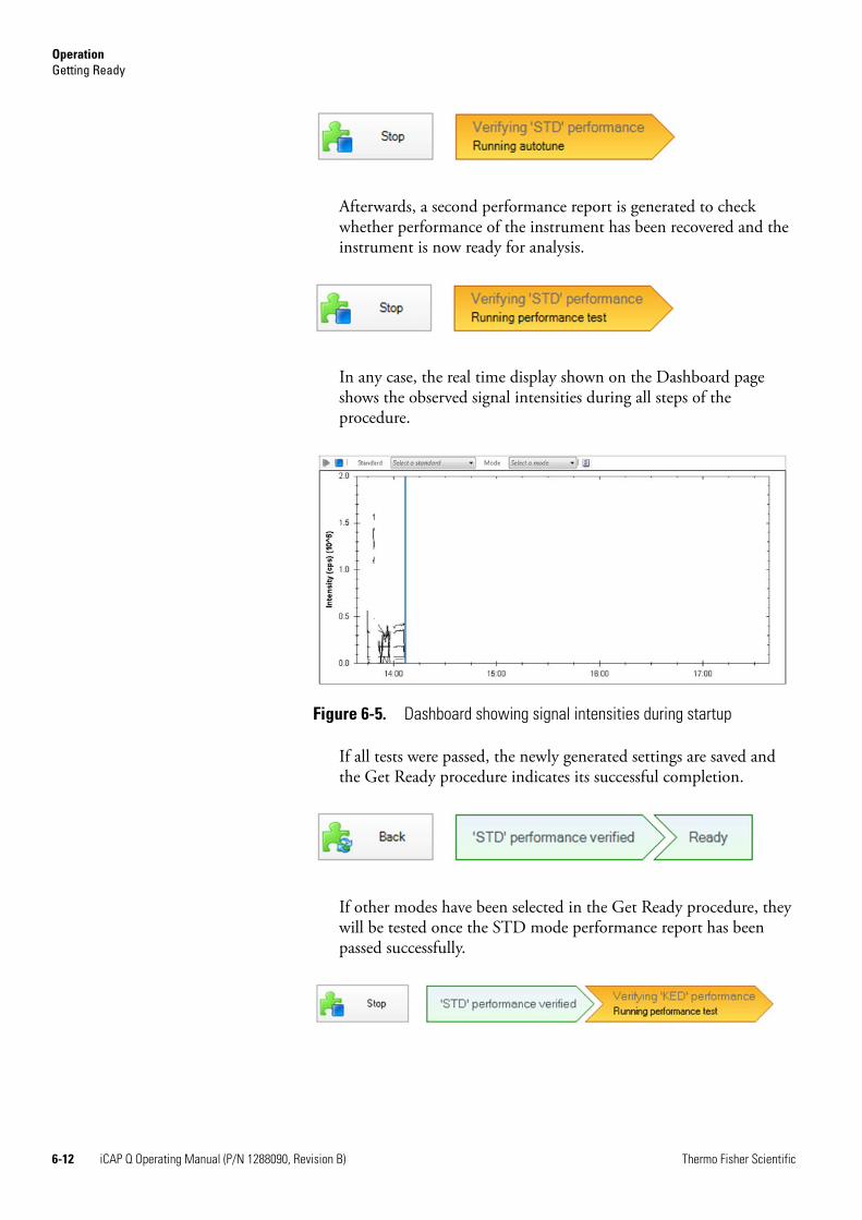
OperationGetting Ready
Afterwards, a second performance report is generated to check whether performance of the instrument has been recovered and the instrument is now ready for analysis.
In any case, the real time display shown on the Dashboard page shows the observed signal intensities during all steps of the procedure.
If all tests were passed, the newly generated settings are saved and the Get Ready procedure indicates its successful completion.
If other modes have been selected in the Get Ready procedure, they will be tested once the STD mode performance report has been passed successfully.
Figure 6-5. Dashboard showing signal intensities during startup
6-12 iCAP Q Operating Manual (P/N 1288090, Revision B) Thermo Fisher Scientific
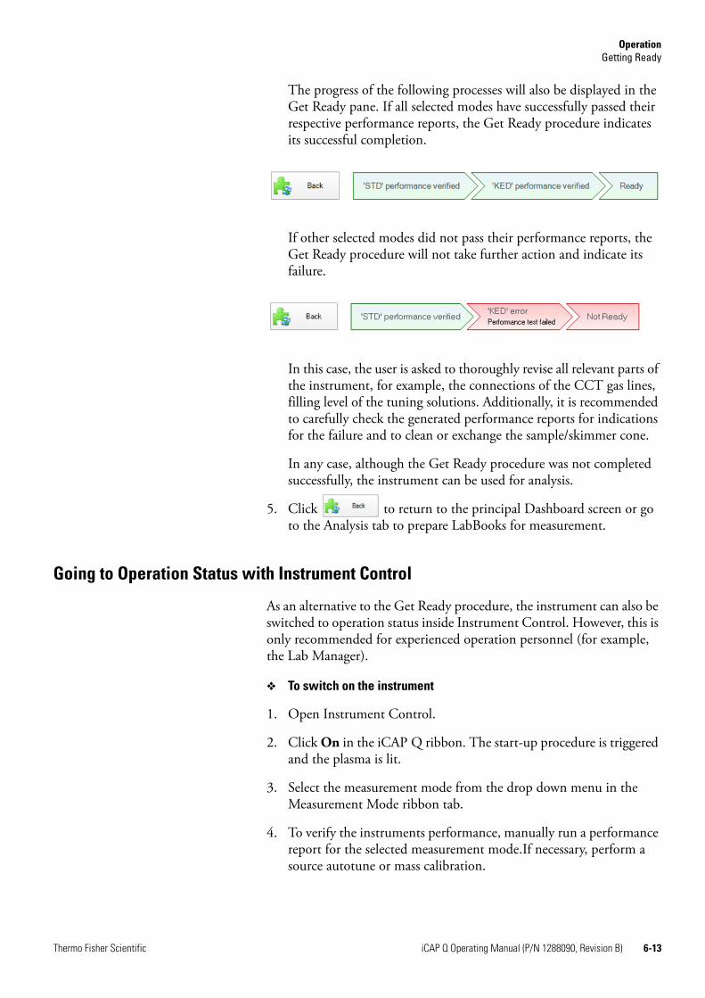
OperationGetting Ready
The progress of the following processes will also be displayed in the Get Ready pane. If all selected modes have successfully passed their respective performance reports, the Get Ready procedure indicates its successful completion.
If other selected modes did not pass their performance reports, the Get Ready procedure will not take further action and indicate its failure.
In this case, the user is asked to thoroughly revise all relevant parts of the instrument, for example, the connections of the CCT gas lines, filling level of the tuning solutions. Additionally, it is recommended to carefully check the generated performance reports for indications for the failure and to clean or exchange the sample/skimmer cone.
In any case, although the Get Ready procedure was not completed successfully, the instrument can be used for analysis.
5. Click to return to the principal Dashboard screen or go to the Analysis tab to prepare LabBooks for measurement.
Going to Operation Status with Instrument Control
As an alternative to the Get Ready procedure, the instrument can also be switched to operation status inside Instrument Control. However, this is only recommended for experienced operation personnel (for example, the Lab Manager).
❖ To switch on the instrument
1. Open Instrument Control.
2. Click On in the iCAP Q ribbon. The start-up procedure is triggered and the plasma is lit.
3. Select the measurement mode from the drop down menu in the Measurement Mode ribbon tab.
4. To verify the instruments performance, manually run a performance report for the selected measurement mode.If necessary, perform a source autotune or mass calibration.
Thermo Fisher Scientific iCAP Q Operating Manual (P/N 1288090, Revision B) 6-13
OperationWorking with LabBooks
Working with LabBooksUsually, your Lab Manager will provide you a template or a prepared LabBook for the measurements that are done upon a routine basis. These templates can be converted into Labbooks, which are then loaded inside the Experiment Editor.
For the data evaluation methods available in Qtegra, see Table 6-2:
Loading a LabBook
❖ To load a LabBook
1. On the Home Page of the Experiment Editor, click the Analysis tab to display the Analysis page.
2. Open a recent LabBook or an existing LabBook:
• To load a recent LabBook, click a LabBook in the Recent LabBooks section.
• To load an existing LabBook, do the following:
a. Click Open in the Open LabBook section.
b. In the Browse for LabBook dialog box, select a LabBook.
c. Click OK to open the LabBook.
3. The LabBook opens in a new tab of the Experiment Editor.
Table 6-2. Evaluation methods in Qtegra
Method Description
aQuant Data evaluation method for standard addition
eQuant Data evaluation method for external calibration
Raw data Data evaluation method on raw data only
rQuant Data evaluation method for isotope dilution analysis
tQuant Data evaluation method for time resolved analysis (for example chromatography)
trQuant Data evaluation method for time resolved analysis (for example laser ablation)
6-14 iCAP Q Operating Manual (P/N 1288090, Revision B) Thermo Fisher Scientific
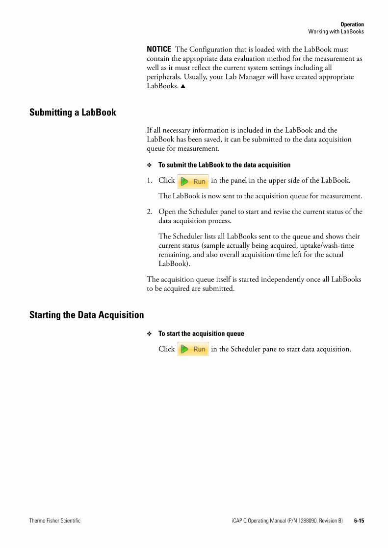
OperationWorking with LabBooks
NOTICE The Configuration that is loaded with the LabBook must contain the appropriate data evaluation method for the measurement as well as it must reflect the current system settings including all peripherals. Usually, your Lab Manager will have created appropriate LabBooks. ▲
Submitting a LabBook
If all necessary information is included in the LabBook and the LabBook has been saved, it can be submitted to the data acquisition queue for measurement.
❖ To submit the LabBook to the data acquisition
1. Click in the panel in the upper side of the LabBook.
The LabBook is now sent to the acquisition queue for measurement.
2. Open the Scheduler panel to start and revise the current status of the data acquisition process.
The Scheduler lists all LabBooks sent to the queue and shows their current status (sample actually being acquired, uptake/wash-time remaining, and also overall acquisition time left for the actual LabBook).
The acquisition queue itself is started independently once all LabBooks to be acquired are submitted.
Starting the Data Acquisition
❖ To start the acquisition queue
Click in the Scheduler pane to start data acquisition.
Thermo Fisher Scientific iCAP Q Operating Manual (P/N 1288090, Revision B) 6-15
OperationAfter Operation
After OperationAfter the experiments are finished, the following routing procedures are recommended:
• Flushing the system
• Releasing the peristaltic pump tubings
• Emptying the waste container
Run the System with Blanks
After operation it is recommended to flush the iCAP Q mass spectrometer with appropriate blanks to such as diluted nitric acid or ultrapure water.This ensures that neither high amounts of analytes nor matrix stay inside the sample introduction system over a longer period of time.
❖ To flush the iCAP Q mass spectrometer
1. Move the probe to a vial containing an appropriate blank solution.
2. Let the system flush with the blank solution for about 5 to 10 minutes.
Release Peristaltic Pump Tubing
To maintain their flexibility, it is also important to release the tubings from the peristaltic pump.
❖ To release the tubing
1. Open the brackets at the peristaltic pump.
2. Remove the collar from the tube.
3. Take out the tube from the sample solution.
Emptying the Waste Container
The liquid level of the waste container needs to be checked before, during, and after operation of the system to prevent an emission of hazardous chemicals.
❖ To empty the waste container
1. Check the solvent level in the solvent waste container.
2. Empty the solvent waste container if necessary. Dispose of the solvent waste in accordance with national and local regulations.
6-16 iCAP Q Operating Manual (P/N 1288090, Revision B) Thermo Fisher Scientific
Chapter 7 Troubleshooting
This chapter goes through the most typical trivial problems that might occur with the instrument. It will help you to diagnose a particular problem and will recommend remedial action. Many problems in high performance instrumentation are the result of trivial concerns, usually after some routine maintenance, or if another operator has left the instrument in a non-standard configuration.
It contains the following topics:
• “General Remarks” on page 7-2
• “Safety Guidelines for Troubleshooting” on page 7-2
• “Error Messages” on page 7-4
• “Sensitivity Problems/No Signal” on page 7-7
• “Signal Drifts with Time” on page 7-8
• “Poor Signal Stability” on page 7-9
Thermo Fisher Scientific iCAP Q Operating Manual (P/N 1288090, Revision B) 7-1
TroubleshootingGeneral Remarks
General RemarksThe two rules of diagnosing potential problems are to:
• Examine the recent history of use of the instrument
• Consider the simple causes first(for example, sample introduction failure is more likely than quadrupole failure)
The single most useful tool for probing analytical concerns and hardware problems is the performance report.
If you have any doubts about the performance of your instrument, trained Thermo Fisher Scientific Technical Support personnel are always available to assist you, however trivial you think the problem may be.
Administrator/User
The troubleshooting procedures described in the following assume that you are logged in as a Qtegra User. For advanced troubleshooting procedures, access rights to the Instrument Control window are required.
Safety Guidelines for TroubleshootingWhen performing troubleshooting on the iCAP Q system, please pay attention to the following general safety guidelines.
CAUTION! Service by the customer must be performed by trained qualified personnel only and is restricted to servicing mechanical parts. Service on electronic parts must be performed by Thermo Fisher Scientific field service engineers only.Never try to repair or replace any component of the system that is not described in this manual without the assistance of your Thermo Fisher Scientific field service engineer.
WARNING!Burn Hazard. Fore vacuum pump in function is hot and some surfaces could reach a temperature higher than 80 °C (176 °F). Take note of the warning labels on the pump.
7-2 iCAP Q Operating Manual (P/N 1288090, Revision B) Thermo Fisher Scientific

TroubleshootingSafety Guidelines for Troubleshooting
WARNING!Electric Shock Hazard. High voltages capable of causing personal injury are used in the instrument. Do not remove protective covers from PCBs. Opening the instrument housing is only allowed for maintenance purposes by Thermo Fisher Scientific personnel. To ensure that the instrument is free from all electric current, always disconnect the power cords of mass spectrometer and fore vacuum pump before attempting any type of maintenance.
Thermo Fisher Scientific iCAP Q Operating Manual (P/N 1288090, Revision B) 7-3
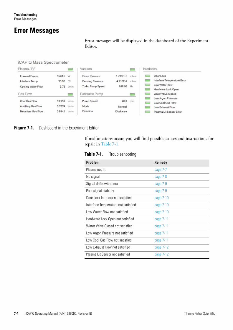
TroubleshootingError Messages
Error MessagesError messages will be displayed in the dashboard of the Experiment Editor.
If malfunctions occur, you will find possible causes and instructions for repair in Table 7-1.M
Figure 7-1. Dashboard in the Experiment Editor
Table 7-1. Troubleshooting
Problem Remedy
Plasma not lit page 7-7
No signal page 7-8
Signal drifts with time page 7-9
Poor signal stability page 7-9
Door Lock Interlock not satisfied page 7-10
Interface Temperature not satisfied page 7-10
Low Water Flow not satisfied page 7-10
Hardware Lock Open not satisfied page 7-11
Water Valve Closed not satisfied page 7-11
Low Argon Pressure not satisfied page 7-11
Low Cool Gas Flow not satisfied page 7-11
Low Exhaust Flow not satisfied page 7-12
Plasma Lit Sensor not satisfied page 7-12
7-4 iCAP Q Operating Manual (P/N 1288090, Revision B) Thermo Fisher Scientific
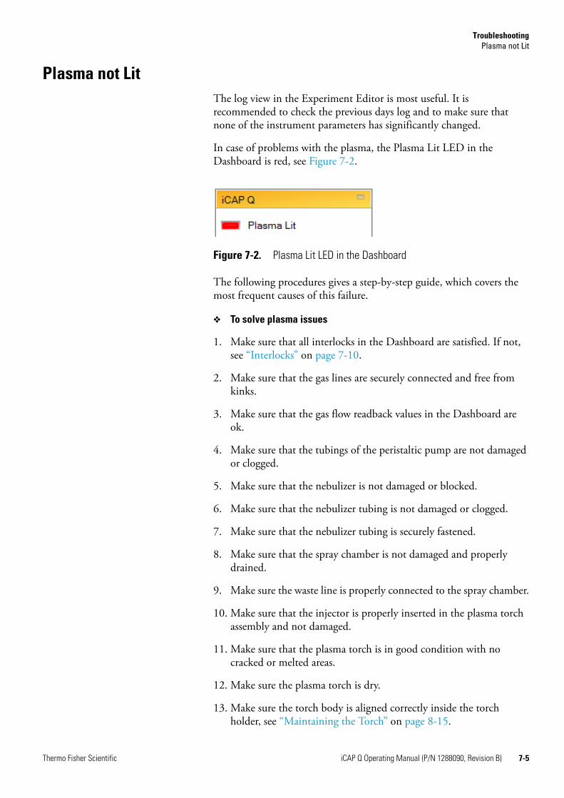
TroubleshootingPlasma not Lit
Plasma not LitThe log view in the Experiment Editor is most useful. It is recommended to check the previous days log and to make sure that none of the instrument parameters has significantly changed.
In case of problems with the plasma, the Plasma Lit LED in the Dashboard is red, see Figure 7-2.
The following procedures gives a step-by-step guide, which covers the most frequent causes of this failure.
❖ To solve plasma issues
1. Make sure that all interlocks in the Dashboard are satisfied. If not, see “Interlocks” on page 7-10.
2. Make sure that the gas lines are securely connected and free from kinks.
3. Make sure that the gas flow readback values in the Dashboard are ok.
4. Make sure that the tubings of the peristaltic pump are not damaged or clogged.
5. Make sure that the nebulizer is not damaged or blocked.
6. Make sure that the nebulizer tubing is not damaged or clogged.
7. Make sure that the nebulizer tubing is securely fastened.
8. Make sure that the spray chamber is not damaged and properly drained.
9. Make sure the waste line is properly connected to the spray chamber.
10. Make sure that the injector is properly inserted in the plasma torch assembly and not damaged.
11. Make sure that the plasma torch is in good condition with no cracked or melted areas.
12. Make sure the plasma torch is dry.
13. Make sure the torch body is aligned correctly inside the torch holder, see “Maintaining the Torch” on page 8-15.
Figure 7-2. Plasma Lit LED in the Dashboard
Thermo Fisher Scientific iCAP Q Operating Manual (P/N 1288090, Revision B) 7-5
TroubleshootingPlasma not Lit
14. Make sure that the torch body O-rings are free from dirt.
15. Make sure that the load coil is in good condition with no burns or damages.
16. Make sure that the waste tubing is inserted in the waste container and the waste container is empty.
17. Make sure that the sample cone is in good condition.
18. Make sure the Forward Power during ignition is 900 W or greater.
19. Make sure that the cooling water meets the conductivity requirements.
If the problem remains, contact the Qtegra Administrator for further troubleshooting.
7-6 iCAP Q Operating Manual (P/N 1288090, Revision B) Thermo Fisher Scientific
TroubleshootingSensitivity Problems/No Signal
Sensitivity Problems/No SignalThe majority of concerns about performance surround an aspect of signal sensitivity.
In most cases, the problems are trivial, caused by a recent change in the sample introduction system or tuning, and can be addressed with ease. Only occasionally are they caused by failure of a critical component.
The log view in the Experiment Editor is most useful. It is recommended to check the previous days log and to make sure that none of the instrument parameters has significantly changed.
❖ To solve signal problems
• If no signal is found:
a. Make sure that the instrument is ready for operation.
b. Make sure that all cables between instrument and computer are securely connected.
If none of the above shows any improvements on the signal, contact the Qtegra Administrator for further troubleshooting.
• If a signal is found:
a. Check the solution concentration.
b. Check that the aspirated sample is visible in the spray chamber.
c. Make sure that the cool gas flow and auxiliary gas flow readbacks are correct and stable.
d. Make sure that the torch body is aligned correctly inside the torch holder, see “Maintaining the Torch” on page 8-15.
e. Make sure that the Pirani readback pressure is approx. 1.9 mbar (± 0.1 mbar).
f. Make sure that the cones and sample cone gasket are in good condition.
If none of the above shows any improvements on the signal, contact the Qtegra Administrator for further troubleshooting.
Thermo Fisher Scientific iCAP Q Operating Manual (P/N 1288090, Revision B) 7-7
TroubleshootingSignal Drifts with Time
Signal Drifts with TimeThe usual cause of signal drift is deposition of matrix on the sample and skimmer cones. As material builds up, the sampling and skimmer orifices become smaller, and the total ion beam is reduced. Removal and cleaning of the cones will resolve this problem, see “Maintaining the Interface” on page 8-17.
The log view in the Experiment Editor is most useful. It is recommended to check the previous days log and to make sure that none of the instrument parameters has significantly changed.
❖ To check for an instrumental drift
1. Ensure that the total dissolved solids level of the solution being aspirated is below the recommended levels.
2. Check that the laboratory temperature is stable.
3. Check that the temperature of the cooling water supplied to the instrument is stable.
4. Make sure that the cooling water lines at the Peltier cooler are securely connected.
5. Make sure that the pump speed of the Peristaltic pump is stable.
6. Make sure that the vacuum system is stable.
7. Make sure that the tubings of the peristaltic pump are not damaged or clogged.
8. Make sure that the nebulizer is not damaged or blocked.
9. Make sure that the nebulizer tubing is not damaged or clogged.
10. Make sure that the spray chamber is not damaged.
11. Make sure that the plasma torch is in good condition with no cracked or melted areas.
12. Make sure the torch body is aligned correctly inside the torch holder, see “Maintaining the Torch” on page 8-15.
13. Make sure that the waste tubing is inserted in the vessel and the vessel is empty.
14. Check that the tension on the peristaltic pump tubing is correct and that the pump tubing is in good condition.
If none of the above shows any improvements on the signal, contact the Qtegra Administrator for further troubleshooting.
7-8 iCAP Q Operating Manual (P/N 1288090, Revision B) Thermo Fisher Scientific
TroubleshootingPoor Signal Stability
Poor Signal StabilityStability is interpreted as the ability of the instrument to produce good % RSD values on repeats of the same sample (sometimes defined as internal precision). Poor stability is often the reason behind a set of data being discarded. Sample matrix can affect stability, especially if the nebulizer cannot form a stable aerosol. System-related stability problems will occur, if short term stability test % RSD’s worse than 2 to 3% are obtained when running a standard tune solution.
The log view in the Experiment Editor is most useful. It is recommended to check the previous days log and to make sure that none of the instrument parameters has significantly changed.
❖ To solve stability issues
1. Ensure that the total dissolved solids level of the solution being aspirated is below the recommended levels.
2. Check that the laboratory temperature is stable.
3. Check that the temperature of the cooling water supplied to the instrument is stable.
4. Make sure that the gas lines are securely connected, free from kinks, and not trapped.
5. Make sure the gas flow readback values in the Dashboard are stable.
6. Make sure that the tubings of the peristaltic pump are not damaged or clogged and that the tubings are secured with the collars and brackets.
7. Make sure that the nebulizer is not damaged or blocked.
8. Make sure that the nebulizer tubing is not damaged or clogged.
9. Make sure that the spray chamber is not damaged.
10. Make sure that the plasma torch is in good condition with no cracked or melted areas.
11. Make sure the torch body is aligned correctly inside the torch holder, see “Maintaining the Torch” on page 8-15.
12. Make sure that the waste tubing is inserted in the vessel and the vessel is empty.
13. Make sure that the pump speed of the Peristaltic pump is stable.
14. Make sure that the vacuum system is stable.
If none of the above shows any improvements on the signal, contact the Qtegra Administrator for further troubleshooting.
Thermo Fisher Scientific iCAP Q Operating Manual (P/N 1288090, Revision B) 7-9
TroubleshootingInterlocks
InterlocksThe interlocks pane displays possible errors at main components of the instrument.
If you are not able to satisfy the interlocks following the procedures described below, contact the Qtegra Administrator for further troubleshooting.
Door Lock
The Door Lock interlock indicates that the plasma door of the instrument is not firmly shut.
❖ To reset the Door Lock interlock
1. Make sure that the plasma door is closed and firmly secured.
2. If required, open and close the door again.
Interface Temperature
The Interface Temperature interlock indicates that the temperature of the interface exceeds 50° C or has not been below 40°C after exceeding 50°C. Also see the readback value of the interface temperature in the Plasma pane, see Figure 7-1.
The interlock may also be set when the temperature sensor is not connected or damaged.
❖ To reset the Interface Temperature interlock
1. Check the interlocks Low Water Flow and Water Valve Closed.
2. Make sure that the water cooler is switched on.
3. Make sure the water cooling lines are properly connected.
Low Water Flow
The Low Water Flow interlock indicates that the cooling water flow is below a specified threshold. Also see the readback value of the cooling water flow in the Plasma pane, see Figure 7-1 on page 7-4.
❖ To reset the Low Water Flow interlock
1. Make sure that the water cooler is switched on.
2. Make sure that the water cooling lines are properly connected.
7-10 iCAP Q Operating Manual (P/N 1288090, Revision B) Thermo Fisher Scientific
TroubleshootingInterlocks
Hardware Lock Open
The Hardware Lock Open interlock indicates that no torch is fitted or that the torch is not fitted correctly.
❖ To reset the Hardware Lock Open interlock
1. Remove the torch assembly.
2. Check the position of the torch body in the torch holder.
3. Insert the torch assembly again.
Water Valve Closed
The Water Valve Closed interlock indicates that the water valve in the instrument is closed. To reset the Water Valve Closed interlock, contact the Qtegra administrator.
Low Argon Pressure
The Low Argon Pressure interlock indicates that the argon gas flow is not sufficient. Also see the readback value of the gas flow in the Gas Flow pane, see Figure 7-1.
❖ To reset the Low Argon Pressure interlock
1. Check that the argon supply is switched on and can supply 6 bar.
2. Make sure that the gas lines are securely connected, free from kinks, and not trapped.
Low Cool Gas Flow
The Low Cool Gas Flow interlock indicates that the cool gas flow is below 5 L/min and the nebulizer gas flow is below 0.1 L/min or that the cool gas flow is below 10 L/min and the nebulizer gas flow is above 0.1 L/min. Also see the readback value of the cooling gas in the Gas Flow pane, see Figure 7-1 on page 7-4.
❖ To reset the Low Cool Gas Flow interlock
1. Check that the argon supply is switched on and can supply 6 bar.
2. Make sure that the gas lines are securely connected, free from kinks, and not trapped.
Thermo Fisher Scientific iCAP Q Operating Manual (P/N 1288090, Revision B) 7-11
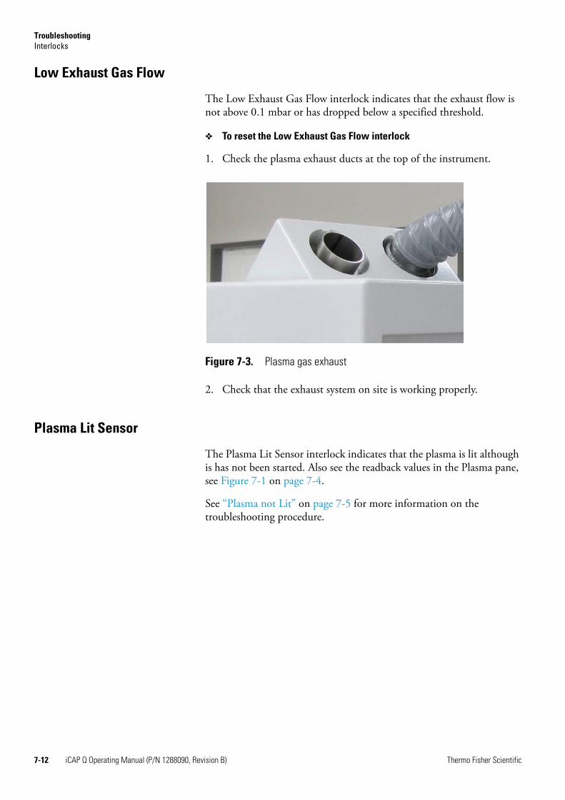
TroubleshootingInterlocks
Low Exhaust Gas Flow
The Low Exhaust Gas Flow interlock indicates that the exhaust flow is not above 0.1 mbar or has dropped below a specified threshold.
❖ To reset the Low Exhaust Gas Flow interlock
1. Check the plasma exhaust ducts at the top of the instrument.
2. Check that the exhaust system on site is working properly.
Plasma Lit Sensor
The Plasma Lit Sensor interlock indicates that the plasma is lit although is has not been started. Also see the readback values in the Plasma pane, see Figure 7-1 on page 7-4.
See “Plasma not Lit” on page 7-5 for more information on the troubleshooting procedure.
Figure 7-3. Plasma gas exhaust
7-12 iCAP Q Operating Manual (P/N 1288090, Revision B) Thermo Fisher Scientific
Chapter 8 Maintenance
This chapter describes routine maintenance procedures that must be performed to ensure optimum performance of the iCAP Q mass spectrometer:
• “Safety Guidelines for Maintenance” on page 8-2
• “General Advice for Maintenance” on page 8-4
• “Servicing Plan” on page 8-5
• “General Maintenance Routines” on page 8-7
• “Maintaining the Air Filter” on page 8-9
• “Maintaining the Inlet System” on page 8-11
• “Maintaining the Interface” on page 8-17
• “Thermo Fisher Scientific Service” on page 8-26
Thermo Fisher Scientific iCAP Q Operating Manual (P/N 1288090, Revision B) 8-1
MaintenanceSafety Guidelines for Maintenance
Safety Guidelines for MaintenanceWhen performing maintenance on the iCAP Q system, please pay attention to the following general safety guidelines.
WARNING!Toxic Gases. Danger of intoxication. Toxic gases are released that might lead to severe bodily harm when the plasma exhaust is not connected to an exhaust system or the spray chamber is disassembled. Do not disassemble the spray chamber when the plasma is still on.
WARNING!Electric Current. Danger of electric shock. High voltages capable of causing personal injury are used in the instrument. Do not remove protective covers from PCBs. Opening the instrument housing is only allowed for maintenance purposes by Thermo Fisher Scientific personnel. To ensure that the instrument is free from all electric current, always disconnect the power cords of mass spectrometer and fore vacuum pump before attempting any type of maintenance.
CAUTION! Corrosive Acids. When handling the corrosive acids required to perform the cleaning procedures described below, take the following precautions. • Wear protective clothing. • Use acid resistant laboratory gloves and glasses.• Make yourself aware of all safety procedures in case of spillage or
exposure to skin or eyes before commencing the cleaning.The acid cleaning should take place in a fume hood.
CAUTION! Hot Surface. Danger of burns. The fore vacuum pump in function is hot and some surfaces could reach a temperature higher than 80 °C (176 °F). Take note of the warning labels on the pump.
CAUTION! UV Radiation. Danger of severe bodily harm. UV radiation is released when the spray chamber is disassembled. UV radiation might lead to severe eye injury or blindness. Do not disassemble the spray chamber when the plasma is still on. Keep a minimum distance of 20 cm when looking into the plasma. Do not operate the system when the plasma door is damaged. A damaged window must be replaced by the Thermo Fisher Scientific field service engineer.
CAUTION! Hot Surface. Danger of burns. Pump in function is hot and some surfaces could reach a temperature higher than 80 °C (176 °F). Also be careful when handling hot pump oil. Take note of warning labels on the pump.
8-2 iCAP Q Operating Manual (P/N 1288090, Revision B) Thermo Fisher Scientific
MaintenanceSafety Guidelines for Maintenance
CAUTION! Hot Surface. Danger of burns. Switch off the plasma two minutes before handling the torch or cones.
CAUTION! Sharp Edges. Danger of cuts. Be careful when handling the glassware because this might break. Wear protective gloves.
CAUTION! Pinch Point Hazard. Danger of injuries. Keep hands clear from the peristaltic pump during operation.
CAUTION! Potentially Harmful Materials. Danger of exposure. Always wear protective gloves and safety glasses when you handle solvents or corrosives. Also contain waste streams and use proper ventilation. Refer to your supplier's Material Safety Data Sheet (MSDS) for proper handling of a particular solvent.
! It is the responsibility of the operator to maintain the system properly by performing the system maintenance procedures on a regular basis.Service by the operator must be performed by trained qualified personnel only and is restricted to servicing mechanical parts. Service on electronic parts must be performed by a Thermo Fisher Scientific field service engineer only.Never try to repair or replace any component of the system that is not described in this manual without the assistance of your Thermo Fisher Scientific field service engineer.Only use fuses of the type and current rating specified. Do not use repaired fuses and do not short-circuit the fuse holder.
Thermo Fisher Scientific iCAP Q Operating Manual (P/N 1288090, Revision B) 8-3
MaintenanceGeneral Advice for Maintenance
General Advice for MaintenanceWhen performing maintenance on the iCAP Q mass spectrometer, observe the following advice:
• Accurate results can be obtained only if the system is in good condition and properly calibrated.
• Preventive maintenance must commence with installation, and must continue during the warranty period to maintain the warranty. Thermo Fisher Scientific offers maintenance and service contracts. Contact your local Thermo Fisher Scientific office for more information. Routine and infrequent maintenance procedures are listed in Table 8-1.
• The operator maintenance procedures described in this manual do not require removing the instrument housing. Thermo Fisher Scientific assumes no responsibility and will not be liable for instrument damage and/or operator injury that might result from using the instrument without the housing attached. Therefore, a Thermo Fisher Scientific field service engineer must be called if removal of the instrument housing is required.
To successfully carry out the procedures listed in this chapter, observe the following rules:
• Proceed methodically.
• Always wear clean, talc-free, and lint-free gloves when handling the components of the iCAP Q mass spectrometer.Thermo Fisher Scientific recommends white nitrile clean room gloves (Fisher Scientific P/N 19-120-2947B, size medium, or P/N 19-120-2947C, size large, or Thermo Scientific P/N 23827-0008, size medium, or P/N 23827-0009, size large).
• Always place the components on a clean, lint-free surface.
• Never overtighten a screw or use excessive force.
• Dirty tools can contaminate your system. Keep the tools clean and use them exclusively for maintenance and service work at the mass spectrometer.
Returning Parts
To protect our employees, we ask you for some special precautions when returning parts for exchange or repair to the factory. Your signature on Health and Safety Form confirms that the returned parts have been de-contaminated and are free of hazardous materials. See “Health and Safety Form” on page 8-26 for further information.
8-4 iCAP Q Operating Manual (P/N 1288090, Revision B) Thermo Fisher Scientific
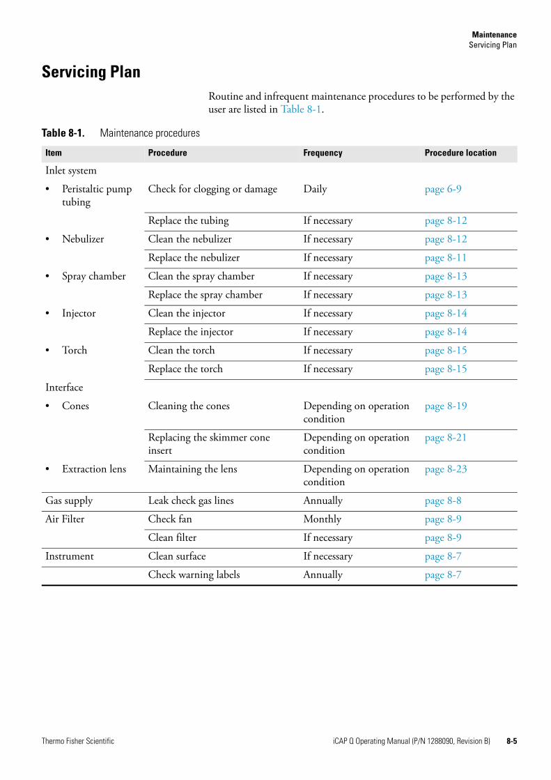
MaintenanceServicing Plan
Servicing PlanRoutine and infrequent maintenance procedures to be performed by the user are listed in Table 8-1.
Table 8-1. Maintenance procedures
Item Procedure Frequency Procedure location
Inlet system
• Peristaltic pump tubing
Check for clogging or damage Daily page 6-9
Replace the tubing If necessary page 8-12
• Nebulizer Clean the nebulizer If necessary page 8-12
Replace the nebulizer If necessary page 8-11
• Spray chamber Clean the spray chamber If necessary page 8-13
Replace the spray chamber If necessary page 8-13
• Injector Clean the injector If necessary page 8-14
Replace the injector If necessary page 8-14
• Torch Clean the torch If necessary page 8-15
Replace the torch If necessary page 8-15
Interface
• Cones Cleaning the cones Depending on operation condition
page 8-19
Replacing the skimmer cone insert
Depending on operation condition
page 8-21
• Extraction lens Maintaining the lens Depending on operation condition
page 8-23
Gas supply Leak check gas lines Annually page 8-8
Air Filter Check fan Monthly page 8-9
Clean filter If necessary page 8-9
Instrument Clean surface If necessary page 8-7
Check warning labels Annually page 8-7
Thermo Fisher Scientific iCAP Q Operating Manual (P/N 1288090, Revision B) 8-5
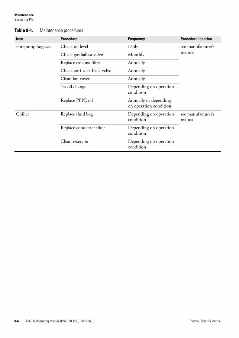
MaintenanceServicing Plan
Forepump Sogevac Check oil level Daily see manufacturer’s manualCheck gas ballast valve Monthly
Replace exhaust filter Annually
Check anti-suck back valve Annually
Clean fan cover Annually
1st oil change Depending on operation condition
Replace PFPE oil Annually or depending on operation condition
Chiller Replace fluid bag Depending on operation condition
see manufacturer’s manual
Replace condenser filter Depending on operation condition
Clean reservoir Depending on operation condition
Table 8-1. Maintenance procedures
Item Procedure Frequency Procedure location
8-6 iCAP Q Operating Manual (P/N 1288090, Revision B) Thermo Fisher Scientific
MaintenanceGeneral Maintenance Routines
General Maintenance Routines
Cleaning the Surface of the Instrument
Clean the outside of the instrument with a dry cloth (preferably made of microfiber). For removing stains or fingerprints on the surface of the instrument (panels, for example), slightly dampen the cloth with distilled water.
NOTICE Prevent any liquids from entering the inside of the instrument. ▲
Cleaning Agents
We recommend having the following cleaning agents available:
• A solvent like isopropanol (in accordance with your local safety practices).
• Several liters of distilled water.
• Aqua regia
• Nitric acid
Checking Warning Labels
The safety warnings on the machine must always be complete, clearly visible and legible.
In addition to the safety instructions that can be found throughout this manual, various warning labels on the instrument inform the user about possible hazards. To protect all personnel working with the instrument/coming near the instrument it is advised to regularly make sure all warning labels on the instrument are still present. See “Safety Symbols on the Instrument” on page 4-3 for an overview of the warning labels on the instrument.
Also check the warning labels on the fore vacuum pump and the peripherals.
Thermo Fisher Scientific iCAP Q Operating Manual (P/N 1288090, Revision B) 8-7
MaintenanceGeneral Maintenance Routines
Checking Gas Lines for Leaks
Regularly leak check each gas line from the gas supply in the laboratory to the instrument.
❖ To perform a leak check for a gas line
1. After closing all valves in the instrument, monitor the manometer of the gas regulator for some minutes.
2. If the pressure falls significantly (for example, the argon pressure falls by more than 10 psi / 690 mbar within two minutes), you should search for leaks in the gas line.
3. Search for leaks in the gas line (for example, by using a conventional thermal conductivity-based leak detector, such as is widely used to check leaks in gas chromatography equipment).
4. If you detect a leak (which is usually at a connection), verify the tightness of the connection. In case of doubt, replace it.
5. When you cannot find a leak in the gas line, we recommend calling a Thermo Fisher Scientific field service engineer to check for gas leaks within the instrument.
8-8 iCAP Q Operating Manual (P/N 1288090, Revision B) Thermo Fisher Scientific
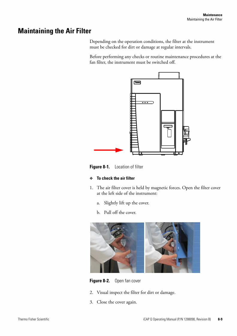
MaintenanceMaintaining the Air Filter
Maintaining the Air FilterDepending on the operation conditions, the filter at the instrument must be checked for dirt or damage at regular intervals.
Before performing any checks or routine maintenance procedures at the fan filter, the instrument must be switched off.
❖ To check the air filter
1. The air filter cover is held by magnetic forces. Open the filter cover at the left side of the instrument:
a. Slightly lift up the cover.
b. Pull off the cover.
2. Visual inspect the filter for dirt or damage.
3. Close the cover again.
Figure 8-1. Location of filter
Figure 8-2. Open fan cover
Thermo Fisher Scientific iCAP Q Operating Manual (P/N 1288090, Revision B) 8-9
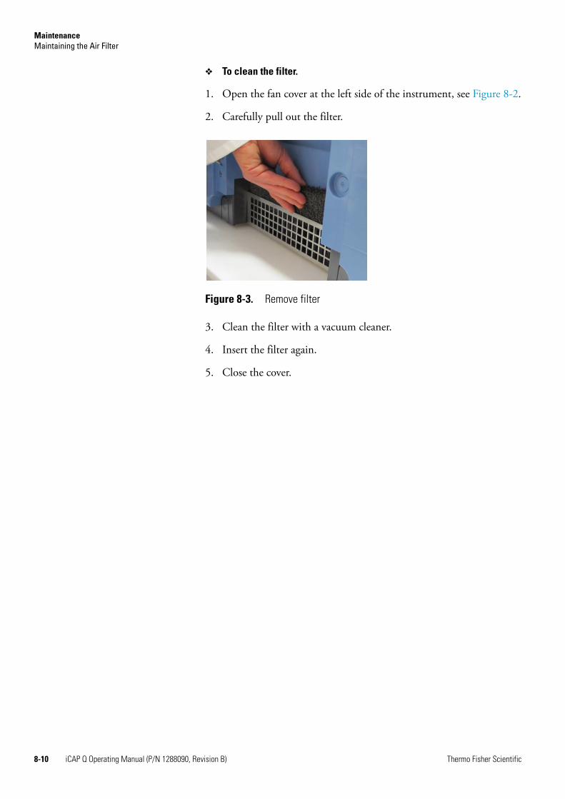
MaintenanceMaintaining the Air Filter
❖ To clean the filter.
1. Open the fan cover at the left side of the instrument, see Figure 8-2.
2. Carefully pull out the filter.
3. Clean the filter with a vacuum cleaner.
4. Insert the filter again.
5. Close the cover.
Figure 8-3. Remove filter
8-10 iCAP Q Operating Manual (P/N 1288090, Revision B) Thermo Fisher Scientific
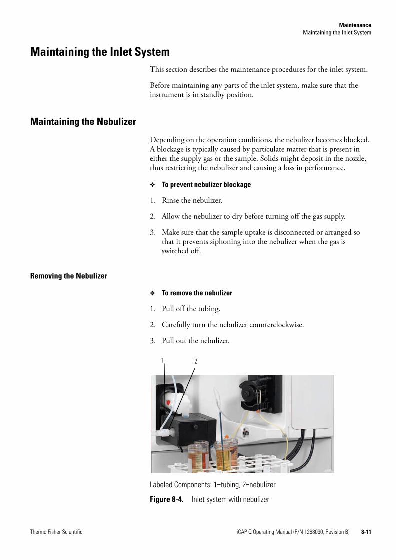
MaintenanceMaintaining the Inlet System
Maintaining the Inlet SystemThis section describes the maintenance procedures for the inlet system.
Before maintaining any parts of the inlet system, make sure that the instrument is in standby position.
Maintaining the Nebulizer
Depending on the operation conditions, the nebulizer becomes blocked. A blockage is typically caused by particulate matter that is present in either the supply gas or the sample. Solids might deposit in the nozzle, thus restricting the nebulizer and causing a loss in performance.
❖ To prevent nebulizer blockage
1. Rinse the nebulizer.
2. Allow the nebulizer to dry before turning off the gas supply.
3. Make sure that the sample uptake is disconnected or arranged so that it prevents siphoning into the nebulizer when the gas is switched off.
Removing the Nebulizer
❖ To remove the nebulizer
1. Pull off the tubing.
2. Carefully turn the nebulizer counterclockwise.
3. Pull out the nebulizer.
Labeled Components: 1=tubing, 2=nebulizer
Figure 8-4. Inlet system with nebulizer
1 2
Thermo Fisher Scientific iCAP Q Operating Manual (P/N 1288090, Revision B) 8-11
MaintenanceMaintaining the Inlet System
Cleaning the Nebulizer
❖ To clean the nebulizer (blockage)
1. If the nozzle is coated with crystalline deposits, soaking in dilute nitric acid should be sufficient
2. If it is still blocked, flush the nebulizer with a 3–5% solution of aqua regia.
3. Rinse the nebulizer thoroughly in clean deionized water.
Inserting the Nebulizer
❖ To insert the nebulizer
1. Carefully insert the nebulizer in the spray chamber.
2. Turn it clockwise to secure it.
3. Connect the nebulizer gas tubing.
Maintaining the Peristaltic Pump
The condition of the peristaltic pump tubing can affect the stability of the ion beam. Therefore, the peristaltic pump tubing should be replaced regularly.
❖ To maintain the peristaltic pump
1. Make sure the peristaltic pump is not running.
2. Wipe the surface of the peristaltic pump rollers and tension arms with a dry cloth to remove any dust.
CAUTION! Corrosive Acid. When handling corrosive acids such as aqua regia, take the following precautions:• Wear protective clothes.• Always use acid resistant laboratory gloves and glasses.• Make yourself aware of all safety procedures in case of spillage or
exposure to the skin or eyes before commencing the cleaning.• The acid cleaning of the glassware should take place in a fume hood.
Follow the local health and safety procedures.
CAUTION! Pinch Point Hazard. Danger of injuries. Keep hands clear from the peristaltic pump during operation.
8-12 iCAP Q Operating Manual (P/N 1288090, Revision B) Thermo Fisher Scientific
MaintenanceMaintaining the Inlet System
3. Replace the sample uptake tubing. If it proves difficult to insert the PTFE tubing in the ends, widen them by inserting the tip of a clean micro pipette tip.
4. Replace the drain tubing.
5. Place the two tubes around the barrel rollers:
a. Make sure that they are not twisted.
b. Secure them in place using the collars and brackets.
6. Attach the tension arms.
7. Ensure that the tubes are fitted for correct sample and drain flow direction when the peristaltic pump is in operation.
8. Switch on the peristaltic pump in the Instrument Control.
NOTICE You must be logged in as Qtegra Administrator to access the Instrument Control window. ▲
9. Check that the sample is being taken up into the instrument and being drained efficiently.
10. If needed, adjust the tension of the tubing using the thumbscrews on the peristaltic pump.
NOTICE If an autosampler is being used, it is recommended to renew the wash station tubing whenever the sample uptake and drain tubing are changed. ▲
Maintaining the Spray Chamber
Removing the Spray Chamber
❖ To remove the spray chamber
1. Remove the nebulizer, see “Removing the Nebulizer” on page 8-11.
2. Remove the Peltier cooling:
a. Remove the thumb screw at the Peltier cooling.
b. Carefully remove the lid.
c. Pull back the holder spring to release the spray chamber.
3. Carefully pull out the spray chamber and the elbow connector from the torch assembly by pulling out the elbow connector.
Thermo Fisher Scientific iCAP Q Operating Manual (P/N 1288090, Revision B) 8-13
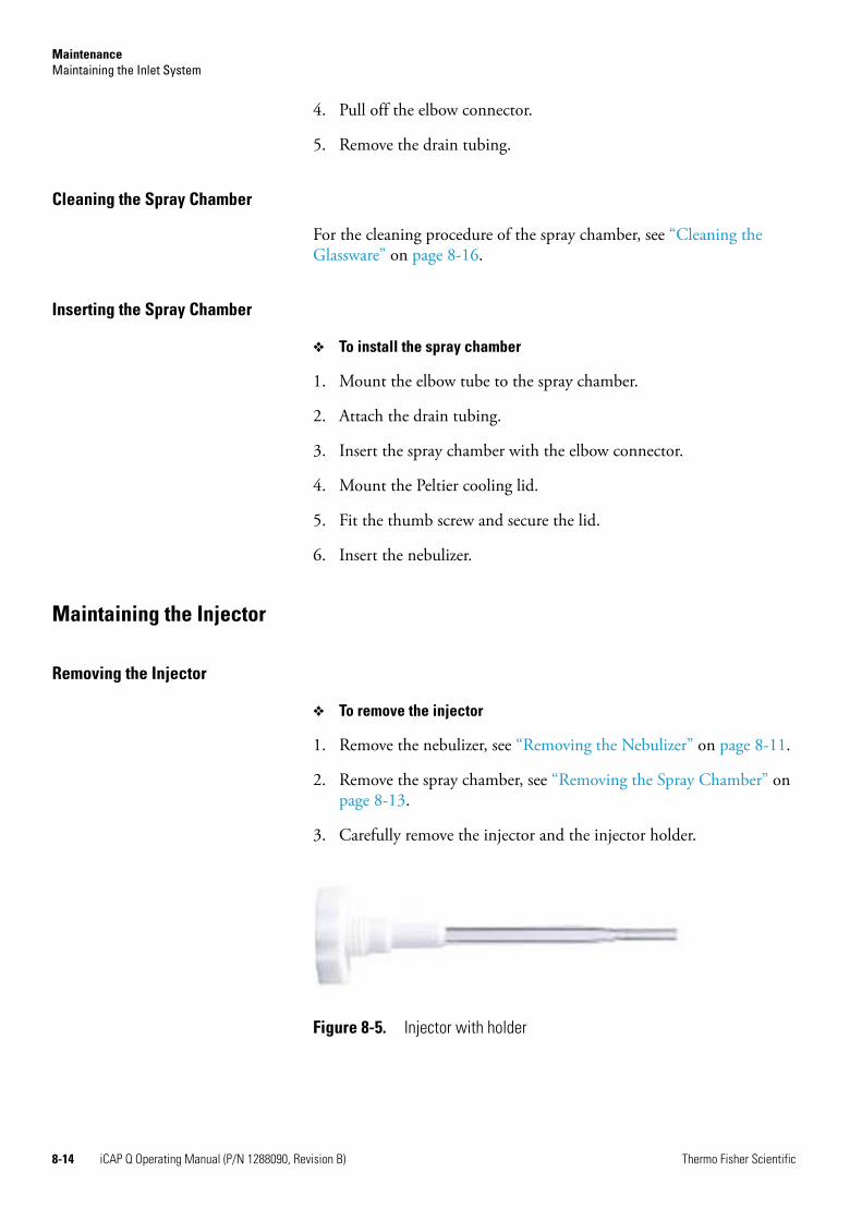
MaintenanceMaintaining the Inlet System
4. Pull off the elbow connector.
5. Remove the drain tubing.
Cleaning the Spray Chamber
For the cleaning procedure of the spray chamber, see “Cleaning the Glassware” on page 8-16.
Inserting the Spray Chamber
❖ To install the spray chamber
1. Mount the elbow tube to the spray chamber.
2. Attach the drain tubing.
3. Insert the spray chamber with the elbow connector.
4. Mount the Peltier cooling lid.
5. Fit the thumb screw and secure the lid.
6. Insert the nebulizer.
Maintaining the Injector
Removing the Injector
❖ To remove the injector
1. Remove the nebulizer, see “Removing the Nebulizer” on page 8-11.
2. Remove the spray chamber, see “Removing the Spray Chamber” on page 8-13.
3. Carefully remove the injector and the injector holder.
Figure 8-5. Injector with holder
8-14 iCAP Q Operating Manual (P/N 1288090, Revision B) Thermo Fisher Scientific
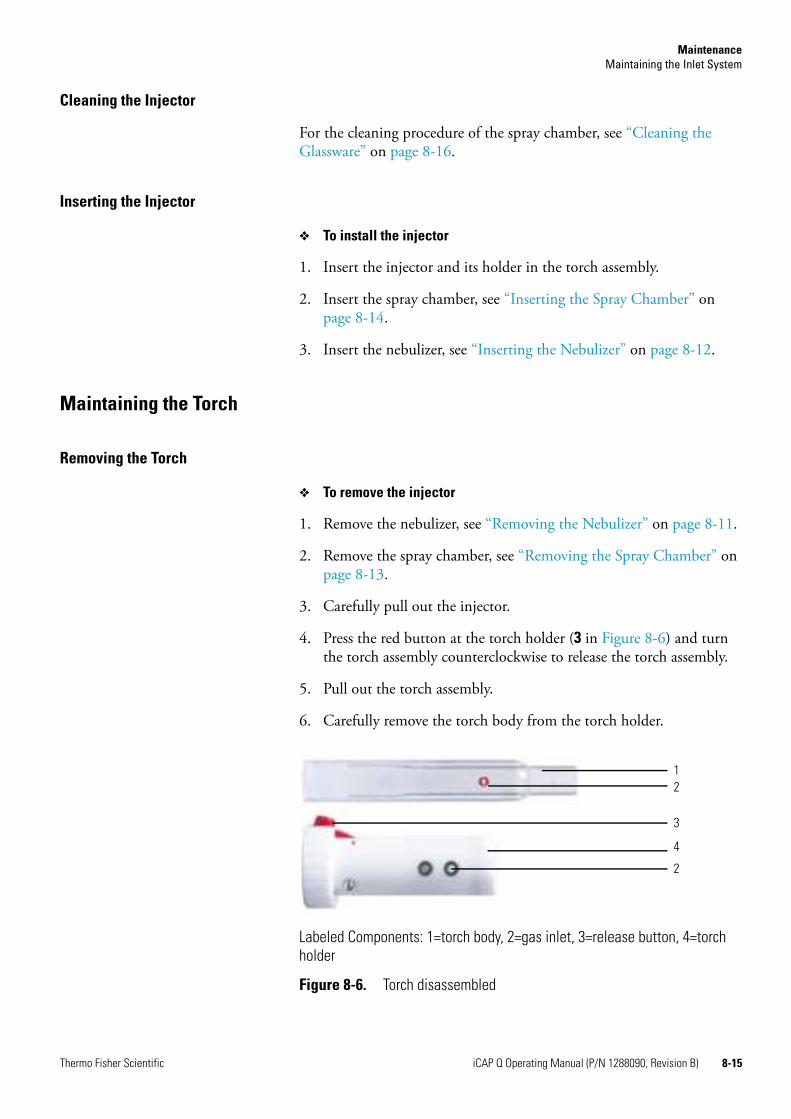
MaintenanceMaintaining the Inlet System
Cleaning the Injector
For the cleaning procedure of the spray chamber, see “Cleaning the Glassware” on page 8-16.
Inserting the Injector
❖ To install the injector
1. Insert the injector and its holder in the torch assembly.
2. Insert the spray chamber, see “Inserting the Spray Chamber” on page 8-14.
3. Insert the nebulizer, see “Inserting the Nebulizer” on page 8-12.
Maintaining the Torch
Removing the Torch
❖ To remove the injector
1. Remove the nebulizer, see “Removing the Nebulizer” on page 8-11.
2. Remove the spray chamber, see “Removing the Spray Chamber” on page 8-13.
3. Carefully pull out the injector.
4. Press the red button at the torch holder (3 in Figure 8-6) and turn the torch assembly counterclockwise to release the torch assembly.
5. Pull out the torch assembly.
6. Carefully remove the torch body from the torch holder.
Labeled Components: 1=torch body, 2=gas inlet, 3=release button, 4=torch holder
Figure 8-6. Torch disassembled
1
3
4
2
2
Thermo Fisher Scientific iCAP Q Operating Manual (P/N 1288090, Revision B) 8-15
MaintenanceMaintaining the Inlet System
Cleaning the Torch
For the cleaning procedure of the torch, see “Cleaning the Glassware” on page 8-16.
Inserting the Torch
❖ To install the torch
1. Reassemble the torch body and the torch holder. Carefully align the gas inlet (Figure 8-6).
2. Insert the injector.
3. Insert the spray chamber, see “Inserting the Spray Chamber” on page 8-14.
4. Insert the nebulizer, see “Inserting the Nebulizer” on page 8-12.
Cleaning the Glassware
❖ To clean the glassware (torch, spray chamber, injector)
1. Insert the glassware in 10–20% high-purity-grade nitric acid.
2. Clean it in an ultrasonic bath.
3. Remove it from the nitric acid and wash it at least three times in fresh deionized water.
4. Allow it to air dry completely. If any components are to be stored for some time before use, they should be placed in metal-free sealed plastic bags.
CAUTION! Corrosive Acids. When handling the corrosive acids required to perform the cleaning procedures described below, take the following precautions. • Wear protective clothing. • Use acid resistant laboratory gloves and glasses.• Make yourself aware of all safety procedures in case of spillage or
exposure to skin or eyes before commencing the cleaning.The acid cleaning should take place in a fume hood.
8-16 iCAP Q Operating Manual (P/N 1288090, Revision B) Thermo Fisher Scientific
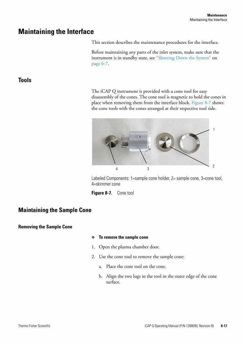
MaintenanceMaintaining the Interface
Maintaining the InterfaceThis section describes the maintenance procedures for the interface.
Before maintaining any parts of the inlet system, make sure that the instrument is in standby state, see “Shutting Down the System” on page 6-7.
Tools
The iCAP Q instrument is provided with a cone tool for easy disassembly of the cones. The cone tool is magnetic to hold the cones in place when removing them from the interface block. Figure 8-7 shows the cone tools with the cones arranged at their respective tool side.
Maintaining the Sample Cone
Removing the Sample Cone
❖ To remove the sample cone
1. Open the plasma chamber door.
2. Use the cone tool to remove the sample cone:
a. Place the cone tool on the cone.
b. Align the two lugs in the tool in the outer edge of the cone surface.
Labeled Components: 1=sample cone holder, 2= sample cone, 3=cone tool, 4=skimmer cone
Figure 8-7. Cone tool
1
234
Thermo Fisher Scientific iCAP Q Operating Manual (P/N 1288090, Revision B) 8-17
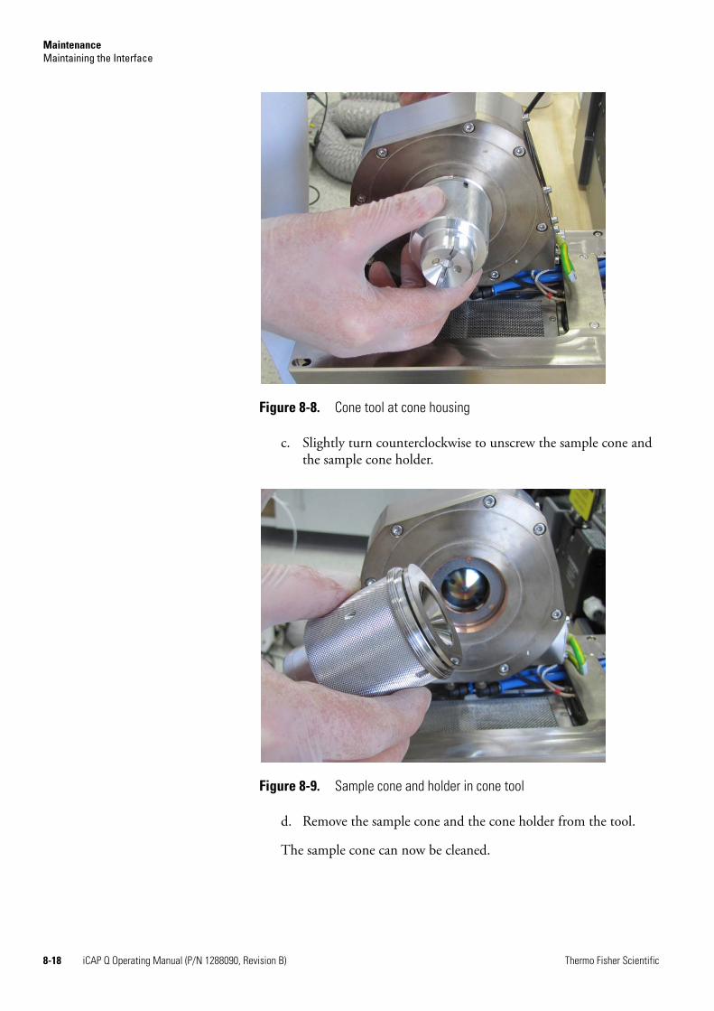
MaintenanceMaintaining the Interface
c. Slightly turn counterclockwise to unscrew the sample cone and the sample cone holder.
d. Remove the sample cone and the cone holder from the tool.
The sample cone can now be cleaned.
Figure 8-8. Cone tool at cone housing
Figure 8-9. Sample cone and holder in cone tool
8-18 iCAP Q Operating Manual (P/N 1288090, Revision B) Thermo Fisher Scientific
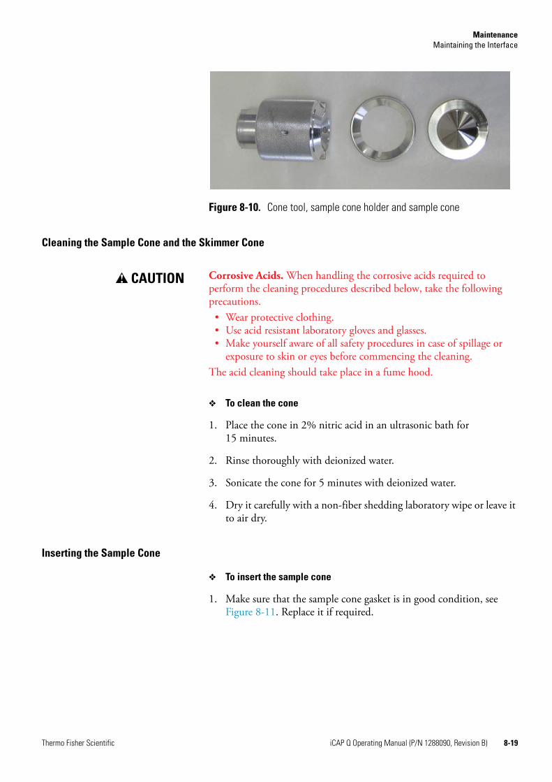
MaintenanceMaintaining the Interface
Cleaning the Sample Cone and the Skimmer Cone
❖ To clean the cone
1. Place the cone in 2% nitric acid in an ultrasonic bath for 15 minutes.
2. Rinse thoroughly with deionized water.
3. Sonicate the cone for 5 minutes with deionized water.
4. Dry it carefully with a non-fiber shedding laboratory wipe or leave it to air dry.
Inserting the Sample Cone
❖ To insert the sample cone
1. Make sure that the sample cone gasket is in good condition, see Figure 8-11. Replace it if required.
Figure 8-10. Cone tool, sample cone holder and sample cone
CAUTION! Corrosive Acids. When handling the corrosive acids required to perform the cleaning procedures described below, take the following precautions. • Wear protective clothing. • Use acid resistant laboratory gloves and glasses.• Make yourself aware of all safety procedures in case of spillage or
exposure to skin or eyes before commencing the cleaning.The acid cleaning should take place in a fume hood.
Thermo Fisher Scientific iCAP Q Operating Manual (P/N 1288090, Revision B) 8-19
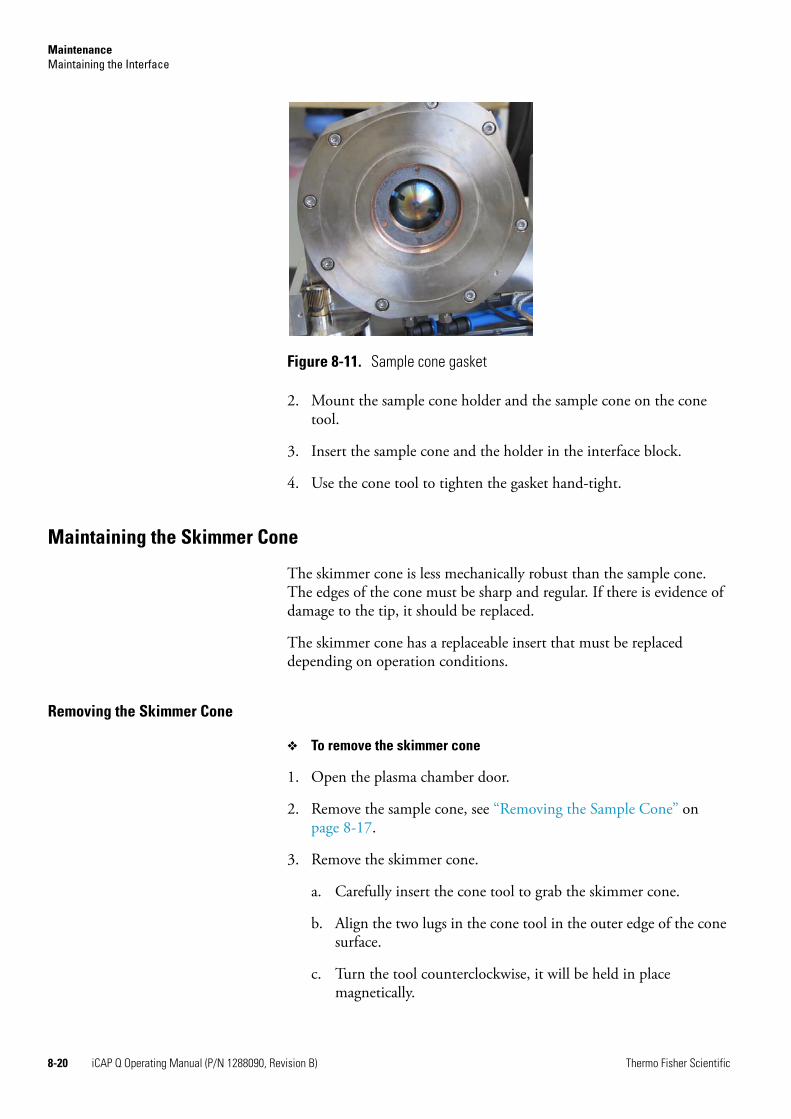
MaintenanceMaintaining the Interface
2. Mount the sample cone holder and the sample cone on the cone tool.
3. Insert the sample cone and the holder in the interface block.
4. Use the cone tool to tighten the gasket hand-tight.
Maintaining the Skimmer Cone
The skimmer cone is less mechanically robust than the sample cone. The edges of the cone must be sharp and regular. If there is evidence of damage to the tip, it should be replaced.
The skimmer cone has a replaceable insert that must be replaced depending on operation conditions.
Removing the Skimmer Cone
❖ To remove the skimmer cone
1. Open the plasma chamber door.
2. Remove the sample cone, see “Removing the Sample Cone” on page 8-17.
3. Remove the skimmer cone.
a. Carefully insert the cone tool to grab the skimmer cone.
b. Align the two lugs in the cone tool in the outer edge of the cone surface.
c. Turn the tool counterclockwise, it will be held in place magnetically.
Figure 8-11. Sample cone gasket
8-20 iCAP Q Operating Manual (P/N 1288090, Revision B) Thermo Fisher Scientific
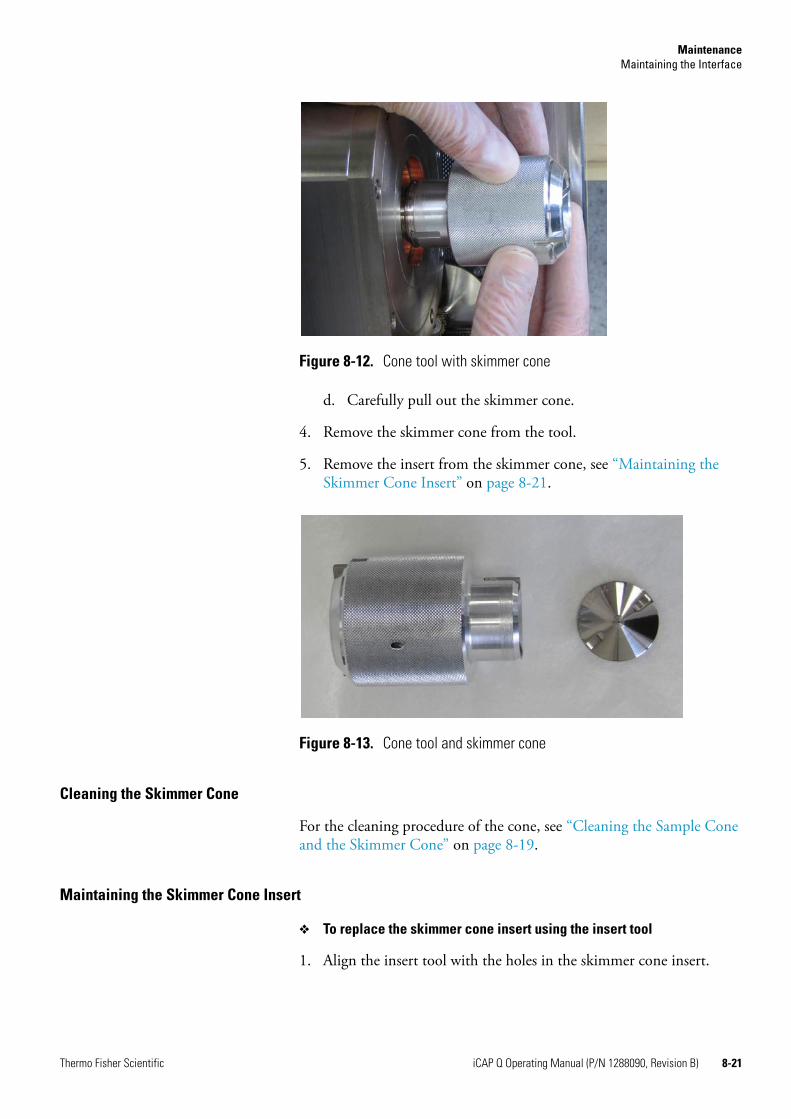
MaintenanceMaintaining the Interface
d. Carefully pull out the skimmer cone.
4. Remove the skimmer cone from the tool.
5. Remove the insert from the skimmer cone, see “Maintaining the Skimmer Cone Insert” on page 8-21.
Cleaning the Skimmer Cone
For the cleaning procedure of the cone, see “Cleaning the Sample Cone and the Skimmer Cone” on page 8-19.
Maintaining the Skimmer Cone Insert
❖ To replace the skimmer cone insert using the insert tool
1. Align the insert tool with the holes in the skimmer cone insert.
Figure 8-12. Cone tool with skimmer cone
Figure 8-13. Cone tool and skimmer cone
Thermo Fisher Scientific iCAP Q Operating Manual (P/N 1288090, Revision B) 8-21
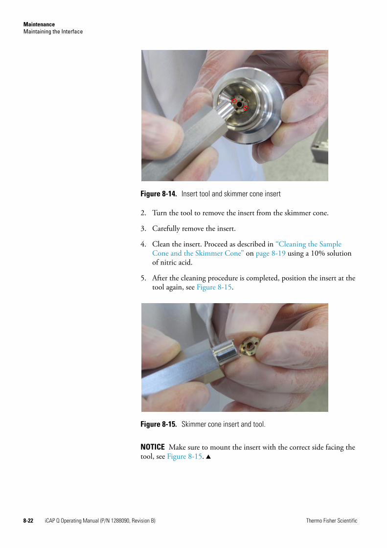
MaintenanceMaintaining the Interface
2. Turn the tool to remove the insert from the skimmer cone.
3. Carefully remove the insert.
4. Clean the insert. Proceed as described in “Cleaning the Sample Cone and the Skimmer Cone” on page 8-19 using a 10% solution of nitric acid.
5. After the cleaning procedure is completed, position the insert at the tool again, see Figure 8-15.
NOTICE Make sure to mount the insert with the correct side facing the tool, see Figure 8-15. ▲
Figure 8-14. Insert tool and skimmer cone insert
Figure 8-15. Skimmer cone insert and tool.
8-22 iCAP Q Operating Manual (P/N 1288090, Revision B) Thermo Fisher Scientific
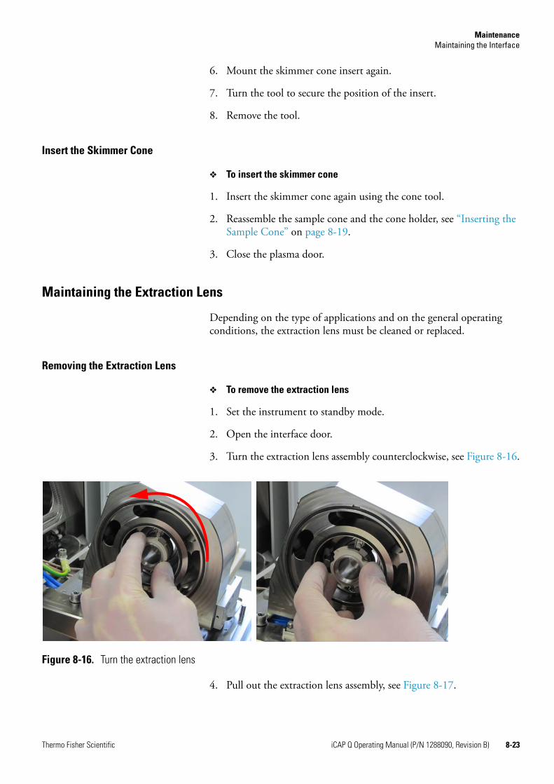
MaintenanceMaintaining the Interface
6. Mount the skimmer cone insert again.
7. Turn the tool to secure the position of the insert.
8. Remove the tool.
Insert the Skimmer Cone
❖ To insert the skimmer cone
1. Insert the skimmer cone again using the cone tool.
2. Reassemble the sample cone and the cone holder, see “Inserting the Sample Cone” on page 8-19.
3. Close the plasma door.
Maintaining the Extraction Lens
Depending on the type of applications and on the general operating conditions, the extraction lens must be cleaned or replaced.
Removing the Extraction Lens
❖ To remove the extraction lens
1. Set the instrument to standby mode.
2. Open the interface door.
3. Turn the extraction lens assembly counterclockwise, see Figure 8-16.
4. Pull out the extraction lens assembly, see Figure 8-17.
Figure 8-16. Turn the extraction lens
Thermo Fisher Scientific iCAP Q Operating Manual (P/N 1288090, Revision B) 8-23
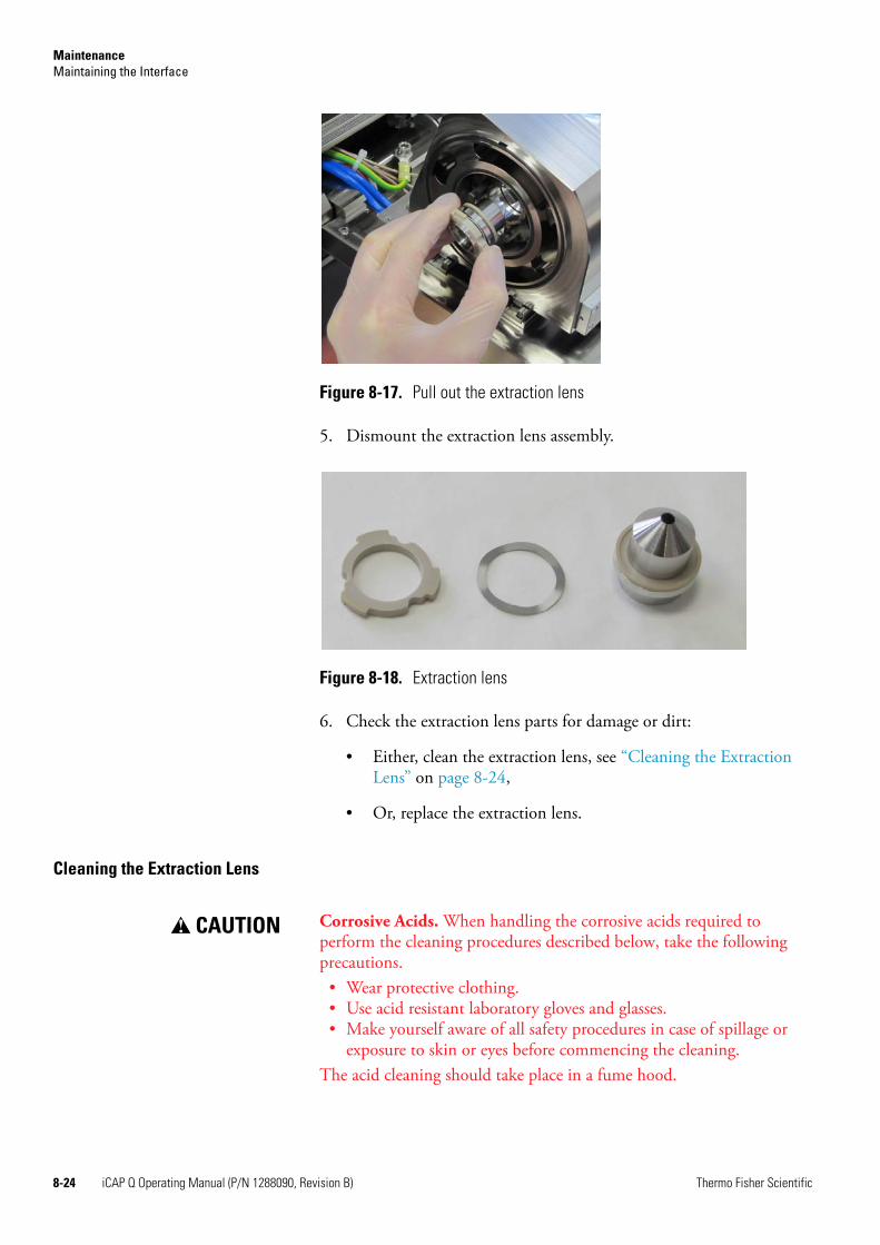
MaintenanceMaintaining the Interface
5. Dismount the extraction lens assembly.
6. Check the extraction lens parts for damage or dirt:
• Either, clean the extraction lens, see “Cleaning the Extraction Lens” on page 8-24,
• Or, replace the extraction lens.
Cleaning the Extraction Lens
Figure 8-17. Pull out the extraction lens
Figure 8-18. Extraction lens
CAUTION! Corrosive Acids. When handling the corrosive acids required to perform the cleaning procedures described below, take the following precautions. • Wear protective clothing. • Use acid resistant laboratory gloves and glasses.• Make yourself aware of all safety procedures in case of spillage or
exposure to skin or eyes before commencing the cleaning.The acid cleaning should take place in a fume hood.
8-24 iCAP Q Operating Manual (P/N 1288090, Revision B) Thermo Fisher Scientific
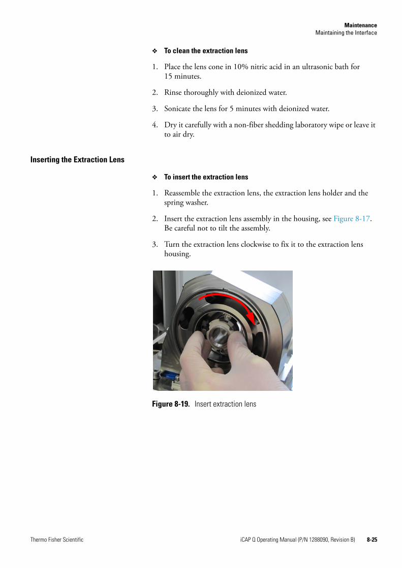
MaintenanceMaintaining the Interface
❖ To clean the extraction lens
1. Place the lens cone in 10% nitric acid in an ultrasonic bath for 15 minutes.
2. Rinse thoroughly with deionized water.
3. Sonicate the lens for 5 minutes with deionized water.
4. Dry it carefully with a non-fiber shedding laboratory wipe or leave it to air dry.
Inserting the Extraction Lens
❖ To insert the extraction lens
1. Reassemble the extraction lens, the extraction lens holder and the spring washer.
2. Insert the extraction lens assembly in the housing, see Figure 8-17.Be careful not to tilt the assembly.
3. Turn the extraction lens clockwise to fix it to the extraction lens housing.
Figure 8-19. Insert extraction lens
Thermo Fisher Scientific iCAP Q Operating Manual (P/N 1288090, Revision B) 8-25
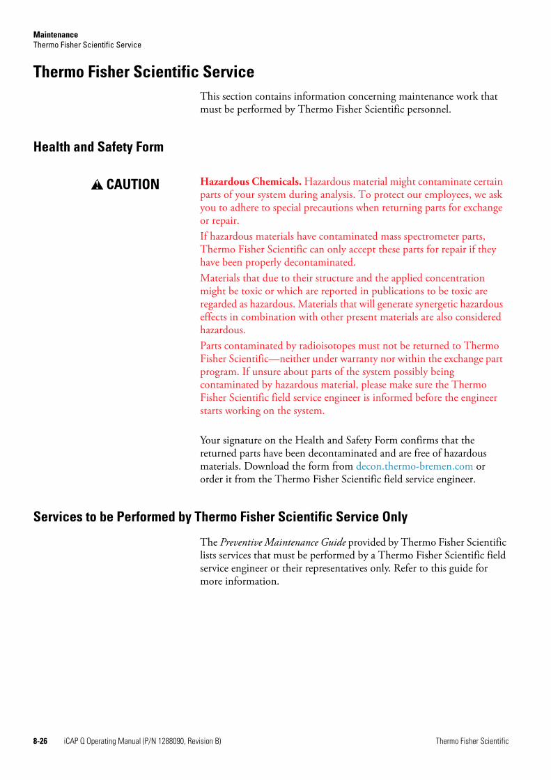
MaintenanceThermo Fisher Scientific Service
Thermo Fisher Scientific ServiceThis section contains information concerning maintenance work that must be performed by Thermo Fisher Scientific personnel.
Health and Safety Form
Your signature on the Health and Safety Form confirms that the returned parts have been decontaminated and are free of hazardous materials. Download the form from decon.thermo-bremen.com or order it from the Thermo Fisher Scientific field service engineer.
Services to be Performed by Thermo Fisher Scientific Service Only
The Preventive Maintenance Guide provided by Thermo Fisher Scientific lists services that must be performed by a Thermo Fisher Scientific field service engineer or their representatives only. Refer to this guide for more information.
CAUTION! Hazardous Chemicals. Hazardous material might contaminate certain parts of your system during analysis. To protect our employees, we ask you to adhere to special precautions when returning parts for exchange or repair.If hazardous materials have contaminated mass spectrometer parts, Thermo Fisher Scientific can only accept these parts for repair if they have been properly decontaminated.Materials that due to their structure and the applied concentration might be toxic or which are reported in publications to be toxic are regarded as hazardous. Materials that will generate synergetic hazardous effects in combination with other present materials are also considered hazardous.Parts contaminated by radioisotopes must not be returned to Thermo Fisher Scientific—neither under warranty nor within the exchange part program. If unsure about parts of the system possibly being contaminated by hazardous material, please make sure the Thermo Fisher Scientific field service engineer is informed before the engineer starts working on the system.
8-26 iCAP Q Operating Manual (P/N 1288090, Revision B) Thermo Fisher Scientific
Chapter 9 Additional Safety Information
This chapter contains excerpts from component suppliers’ documents with safety-relevant information that may concern users of the iCAP Q mass spectrometer. It contains the following topics:
• “Fore Vacuum Pump” on page 9-2
• “Recirculating Chiller” on page 9-4
• “Dionex ICS-5000” on page 9-5
Thermo Fisher Scientific iCAP Q Operating Manual (P/N 1288090, Revision B) 9-1
Additional Safety InformationFore Vacuum Pump
Fore Vacuum PumpFailure to observe the following precautions could result in serious personal injury!
Sogevac™ pumps are not designed:
• For pumping of dusty, aggressive, corrosive, flammable or explosive gases or gases mixtures,
• For pumping of oxygen or other highly reactive gases with a greater concentration than atmospheric concentration (>20%),
• For working in flammable, explosive or dusty environment.
For all these cases, special materials must be used. In case of doubt, please contact Oerlikon Leybold Vacuum. See also the limits of use indicated in the CE declaration of conformity.
Pump must not be operated above 2000 m sea level.
WARNING!High Voltage. When touching parts at high electric voltages, there is the risk of suffering severe injuries by an electric shock! Covers marked with this symbol must only be opened by trained electricians after having reliably deenergized (lockout/tagout) the equipment.Always operate the pump with a properly connected protective earth conductor and make sure that the motor & FC connection box are closed.Observe the manufacturer’s information and operating instructions for the respective frequency converter (enclosed).Use only the OLV frequency converter for the pumps equipped with one.After having made changes to the wiring, check the motor’s direction of rotation.
WARNING!High Voltage. Even if the pump is not operating, there is the risk of suffering severe injuries by an electric shock! Even after complete power disconnection, live voltage is present in the frequency converter. Allow a minimum of 10 minutes for a complete capacitor discharge.
WARNING!Explosion Hazard. The standard pump is not suitable for installation in explosion hazard ATEX areas. Contact the pump manufacturer if you are planning such an application. Before installing the pump, you must reliably disconnect it from the electrical power supply and prevent the pump form running up inadvertently.
9-2 iCAP Q Operating Manual (P/N 1288090, Revision B) Thermo Fisher Scientific
Additional Safety InformationFore Vacuum Pump
CAUTION! Vacuum Hazard. Risk of injury. Never expose part of the body to the vacuum. There is a danger of injury.Never operate the pump with an open and thus accessible inlet. Vacuum connections as well as oil filling and oil draining openings must not be opened during operation of the pump.Depending on the process involved, dangerous substances and oil may escape from the pump. Take the necessary safety precautions!Disconnect the unit from the power supply before starting any work.
CAUTION! Tripping Hazard. Lay electric feed lines so that there is no risk of tripping over these.
CAUTION! Hot Surface. In normal operation, the pump surface temperature can reach 85 °C. There is a risk of burning. Switch off the pump and let it cool down before any intervention or take appropriate precautions. It is recommended to use an oil casing or pump touching protection at high ambient temperatures.As a touching protection, you can use the noise reduction cover.All work on a pump which is “still warm from operation” must be done only whilst wearing protective gloves.Handle the pump only while vented and after having let it cool down.Never remove the oil-fill or oil-drain plugs while the pump is running. There exists the risk of suffering burns. Always wear protective gloves and protective goggles also for protection against the oil.
CAUTION! Hazardous Chemicals. Danger of injury. The pumps use perfluoropolyether (PFPE) as a lubricant. When handling PFPE you should observe the following: During thermal decomposition at temperatures over 290 °C toxic and corrosive gases are released. This is not likely to happen in a Sogevac pump. When handling PFPE keep it way from open fires. Do not smoke with PFPE on your fingers.Touch the inner sections of the pumps only while wearing clean gloves, and use clean tools; do the necessary work in clean and dry rooms.
Thermo Fisher Scientific iCAP Q Operating Manual (P/N 1288090, Revision B) 9-3
Additional Safety InformationRecirculating Chiller
Recirculating Chiller
WARNING!Electric Current. Electric shock hazard. The unit construction provides protection against the risk of electrical shock by grounding appropriate metal parts. The protection may not function unless the power cord is connected to a properly grounded outlet. It is the user's responsibility to assure a proper ground connection is provided.Always turn off the unit and disconnect the power cord from the power source before performing any service or maintenance procedures, or before moving the unit. Never operate the unit with panels removed.Never operate equipment with damaged power cords.
CAUTION! Sharp Edges. Danger of injury. The condenser framing and fins located behind the grill assembly are very sharp. Use caution when removing the assembly. Water-cooled units also have a fan with sharp blades, ensure that the unit is off before removing the assembly.
9-4 iCAP Q Operating Manual (P/N 1288090, Revision B) Thermo Fisher Scientific
Additional Safety InformationDionex ICS-5000
Dionex ICS-5000
WARNING!High Voltage. Electric shock hazard. Disconnect the main power cord from its source and also from the rear panel of the pump or device.
CAUTION! Explosion Hazard. Never pressurize eluent reservoirs above 0.07 MPa (10 psi). Pressurizing reservoirs above this limit can cause the reservoir to explode.
CAUTION! Explosion Hazard. DO NOT CAP THE WASTE CONTAINER: The ICS-5000 Eluent Generator (EG), Atlas Electrolytic Suppressor, and Self-Regenerating Suppressor (SRS) use an electrolytic process that results in the production of small amounts of oxygen or hydrogen gas. To ensure that the gas is not trapped in a closed container and allowed to concentrate, install a 1.3 cm (0.52 in) ID black gas separator waste tube (P/N 045460) in an uncapped waste container. Connect the Waste, Gas Separator line to the waste tube.
CAUTION! Hot Surface. Risk of burns. To avoid injury, wait for the device to cool down before opening the door or performing any maintenance or service procedures.
CAUTION! Hot Surface. Risk of burns. Do not touch any metal parts inside the Thermal Compartment (TC) while it is heating up or after it reaches the set point temperature. Wait for the compartment to cool down before servicing any parts.
CAUTION! Hazardous Chemicals. Risk of injury. Neutralize acidic and caustic wastes before disposal. Dispose of all wastes in accordance with local regulations.
CAUTION! Hazardous Chemicals. Risk of injury. The eluent generator cartridge (EGC) contains one of the following: a corrosive base (KOH, LiOH, or NaOH), a corrosive acid (MSA), or a concentrated K2CO3 solution. Wear protective eye wear and gloves when handling the cartridge.
! The power supply cord is used as the main disconnect device. Make sure the socket-outlet is located near the Detector/Chromatography Module (DC) and is easily accessible.
Thermo Fisher Scientific iCAP Q Operating Manual (P/N 1288090, Revision B) 9-5

Additional Safety InformationDionex ICS-5000
9-6 iCAP Q Operating Manual (P/N 1288090, Revision B) Thermo Fisher Scientific
Legal Documents
This chapter provides legal documents. It contains the following documentation:
• “FCC Compliance Statement” on page D-2
• “WEEE Compliance” on page D-3
• “Declaration of Conformity” on page D-4
Thermo Fisher Scientific iCAP Q Operating Manual (P/N 1288090, Revision B) D-1

Legal DocumentsFCC Compliance Statement
FCC Compliance StatementThis device complies with part 18 of the FCC rules.
D-2 iCAP Q Operating Manual (P/N 1288090, Revision B) Thermo Fisher Scientific
Legal DocumentsWEEE Compliance
WEEE ComplianceThis product is required to comply with the European Union’s Waste Electrical & Electronic Equipment (WEEE) Directive 2002/96/EC. It is marked with the following symbol:
Thermo Fisher Scientific has contracted with one or more recycling/disposal companies in each EU Member State, and this product should be disposed of or recycled through them. Further information on Thermo Fisher Scientific’s compliance with these Directives, the recyclers in your country, and information on Thermo Fisher Scientific products which may assist the detection of substances subject to the RoHS Directive are available at http://www.thermoscientific.com/rohsweee.
Thermo Fisher Scientific iCAP Q Operating Manual (P/N 1288090, Revision B) D-3
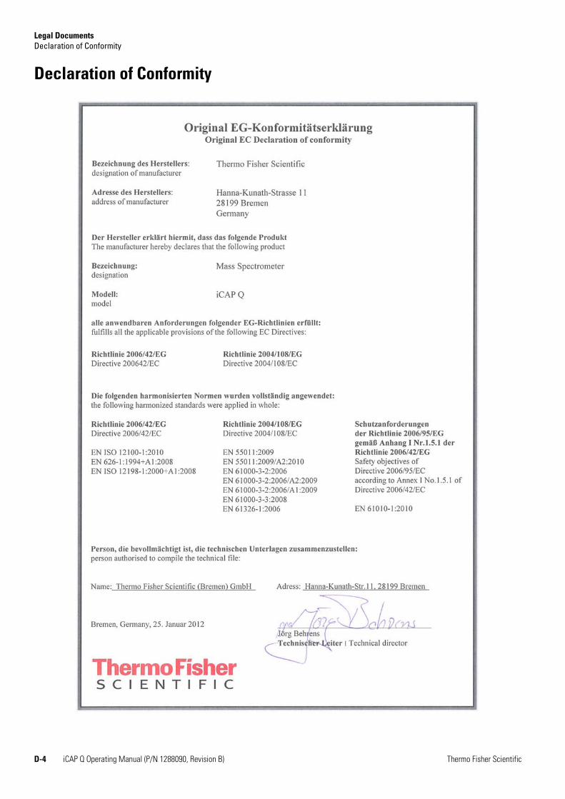
Legal DocumentsDeclaration of Conformity
Declaration of Conformity
D-4 iCAP Q Operating Manual (P/N 1288090, Revision B) Thermo Fisher Scientific
Glossary
This section lists and defines terms used in this manual. It also includes acronyms, metric prefixes, symbols, and abbreviations.
A
ac Abbr. for alternating current, i.e. an electric current that reverses its direction at regularly recurring intervals.
accurate mass The accurate mass is the theoretical ion mass of an isotope or molecule as given by IUPAC (elements.els).
Acid Resistant Sample Inlet resistant inlet with a special nebulizer chamber and torch.
ADC Abbr. for analog-to-digital converter; a device that converts data from analog to digital form.
AIM Abbr. for Active Inverted Magnetron gauge used for vacuum (pressure) measurement; also referred to as Penning gauge.
AL/VI Abbr. for Aluminum/Viton®; material used for gaskets.
analog mode the detection mode “Analog” can be used for high signals between 5 × 10⁴ to 5 × 10⁹ cps. The electrical current measured is converted into the intensity information, which is stored in the data file.
analyte type the following analyte types can be inserted into a sequence: BLK, STD.
APG Abbr. for Active Pirani Gauge used for vacuum (pressure) measurement.
atomic mass unit Atomic Mass Unit (u) defined by taking the mass of one atom of carbon12 as being 12u; unit of mass for expressing masses of atoms or molecules.
aux gas auxiliary gas (argon), serves to generate the plasma.
B
BEC Abbr. for Background Equivalent Concentration (normally in ppt); n=10, depends on the concentration in the blank.
BLK Abbr. for a blank (analyte)
C
°C degrees Celsius.
CE European conformity. Mandatory European marking for certain product groups to indicate conformity with essential health and safety requirements set out in European Directives.
cool gas serves to prevent the glass torch from melting.
counting mode the detection mode “Counting” is a digital measurement and counts electron pulses. It is very sensitive and can be used for the detection of low signals. During acquisition, the number of occurrences is used to generate the intensity information (in counts per seconds) that is stored in the data file.
D
Da Abbr. for dalton; unit of mass equal to the unified atomic mass (atomic mass constant).
DAC Abbr. for digital-to-analog converter; a device that converts data from digital to analog form.
A B C D E F G H I J L L M O O P Q R S T U V W X Y Z
BECblank intensities concentration of standard
intensity standard average intensity blank– --------------------------------------------------------------------------------------------------------------------=
Thermo Fisher Scientific iCAP Q Operating Manual (P/N 1288090, Revision B) G-1
Glossary: dc–PCB
dc Abbr. for direct current, i.e. an electric current flowing in one direction only.
DDS direct digital synthesizer
DSP Abbr. for digital signal processor
E
eV Abbr. for electron volt; the energy gained by an electron which accelerates through a potential difference of one volt.
F
f femto (10-15)
°F degrees Fahrenheit
FTP file transfer protocol
G
G Gauss; giga (109)
GC gas chromatograph; gas chromatography
GC/MS gas chromatograph / mass spectrometer
GND electrical ground
GUI graphical user interface
H
h hour
h height
HPLC high-performance liquid chromatograph
HR Abbr. for High Resolution
HV high voltage
Hz hertz (cycles per second)
I
ICIS™ Interactive Chemical Information System
ID inside diameter
in. inch
internal standards are used in ICP-MS analyses to compensate for drift effects in response or sensitivity caused by various processes in sample introduction or ion extraction.
I/O input/output
ISO Abbr. for isotope dilution (analyte)
L
LAN local area network
lb pound
LC liquid chromatograph; liquid chromatography
LC/MS liquid chromatograph / mass spectrometer
LED light-emitting diode
linear regression type: linear regression analyses.
LOD Abbr. for Limit of Detection (normally in ppt); n=10, depends on the stability of the blank measurement.
LR Abbr. for Low Resolution
M
M+ molecular ion
MH+ protonated molecular ion
MS mass spectrometer; mass spectrometry
m/z mass-to-charge ratio
O
OD outside diameter
P
PCB printed circuit board
LOD3 stdev of BLK intensities concentration of STD
intensity STD average intensity BLK– ---------------------------------------------------------------------------------------------------------------------------------------=
G-2 iCAP Q Operating Manual (P/N 1288090, Revision B) Thermo Fisher Scientific
Glossary: PCL–WEEE
PCL Abbr. for Process Control Language
P/N part number
ppb Abbr. for Parts per billion. A unit of measure expressed as parts per billion. Equivalent to 1 × 10⁻⁹. Similar to μg/L or micrograms per liter.
ppt Abbr. for Part per thousands. A concentration unit of chemical constituents in solution, the weight of solute per unit volume of solvent.
psig pounds per square inch, gauge
R
regression types are used in the creation of calibration curves during a sequence of analyses: the software offers four types: linear, thru zero, weighted, and square fit.
RF radio frequency
S
s second
square fit regression type: the fit is performed with a second order (quadratic) function.
STD Abbr. for standard solution (analyte)
T
TCP/IP transmission control protocol / Internet protocol
U
u see atomic mass unit
UPW (abbr.) Ultra Pure Water
V
V ac volts alternating current
V dc volts direct current
W
weighted regression type: linear regression weighted by the reciprocal of the standard deviation (1/ standard deviation).
WEEE European Union Waste Electrical and Electronic Equipment Directive. Provides guidelines for disposal of electronic waste.
Thermo Fisher Scientific iCAP Q Operating Manual (P/N 1288090, Revision B) G-3

Glossary: WEEE–WEEE
G-4 iCAP Q Operating Manual (P/N 1288090, Revision B) Thermo Fisher Scientific
Index
Numerics23827-0008 4-1023827-0009 4-10Aaccess rights 7-2Active Inverted Magnetron Gauge 3-12Active Pirani Gauge 3-12altitude 5-8aQuant 6-14argon
inlet 3-13properties 3-18requirements 3-14supply 3-14
auxiliary gas 3-6
Ccapillaries 3-13carry handles 5-4CCT gas
connections 3-13outlet 3-15regulator 3-16
CCT mode 3-9, 6-9chiller 6-3cleaning
agent 8-7instrument surface 8-7
clothing 4-10collision cell 3-9Collision Cell Technology (CCT) 3-15cone tool 8-17connections, for fore vacuum pump 3-24contact closure signals 3-25cooling water 3-19
DDA lens 3-10DA plate 3-10Dashboard 3-12dashboard 7-4deposition, of matrix 7-8diagnosing, potential problems 7-2
Door Lock interlock 7-10
Eemergency shutdown 4-12eQuant 6-14error messages 7-4exhaust ports 3-21exhaust system 3-21extraction lens 3-8
Fflatapole, fpole 3-9floor space
with autosampler 5-4without autosampler 5-3
fore vacuum pumpconnections 3-24function 3-12
forepumplifting 5-5
Ggas regulator 3-16get ready procedure 6-10gloves 4-10, 8-4goggles 4-10
Hhandles, for carrying the instrument 5-4Hardware Lock Open interlock 7-11hazardous material 4-10Health and Safety Form 8-4, 8-26helium 3-16–3-17history, of instrument use 7-2humidity 5-8hydrofluoric acid 3-8
Iinjector 3-6in-line filter 3-19installation test 3-16
Thermo Fisher Scientific iCAP Q Operating Manual (P/N 1288090, Revision B) I-1
Index: K–T
Instrument Control window 3-12instrument, moving 5-4interface
block 3-7description 3-7vacuum 3-7
Interface Temperature interlock 7-10ion optics 3-9
KKED mode 3-9, 6-9
Llaboratory
coat 4-10temperature 5-8, 7-8–7-9
laser ablation analysis 3-17leak check, in gas lines 8-8log view 7-5Low Argon Pressure interlock 7-11Low Cool Gas Flow interlock 7-11Low Exhaust Gas Flow interlock 7-12Low Water Flow interlock 7-10
Mmain power supply 3-22–3-23main power switch 3-22–3-23maintaining, the peristaltic pump 8-12mass flow controllers 3-14, 3-17measurement modes 6-9moving
forepump 5-5moving, the instrument 5-4
Nnebulizer 3-5
Oorganic solvents 3-17oxygen 3-17
PPeltier cooler 3-6performance report 6-9peristaltic pump 8-12
personal protective equipment (PPE) 4-10plasma door 3-7plasma gas regulator 3-16Plasma Lit Sensor interlock 7-12polyatomic interferences 3-15Power LED 6-4power requirements 5-7pressure, two-stage gas regulator 3-16
QQCell 3-9Qtegra Administrator 7-6Qtegra User 7-2quadrupole mass analyzer 3-10
RRAPID lens 3-9rating plate 4-5raw data 6-14recirculation water chiller 3-19rQuant 6-14
Ssafety clothing 4-10safety glasses 4-10sample
cone 3-7matrix 7-9
secondary electron multiplier (SEM) 3-10shutdown, in emergency 4-12signal
drifts 7-8problems 7-7sensitivity 7-7
skimmer cone 3-7, 8-20solvent 8-7spray chamber 3-5stability 7-9standby mode 6-7starting, the instrument 6-10STD mode 6-9system control LED 6-4System LED 6-4system status LED 6-4
Ttemperature
coolant water 7-8–7-9
I-2 iCAP Q Operating Manual (P/N 1288090, Revision B) Thermo Fisher Scientific
Index: V–W
laboratory 7-8–7-9tension, on peristaltic pump tubing 7-8torch 3-6total dissolved solids level 7-8–7-9tQuant 6-14transport pallet 5-4trQuant 6-14turbomolecular pump 3-12
VVacuum LED 6-4vibration 5-9
Wwall receptacle 5-7warning labels 8-7Water Valve Closed interlock 7-11
Thermo Fisher Scientific iCAP Q Operating Manual (P/N 1288090, Revision B) I-3

Thermo Fisher Scientific Inc.
81 Wyman Street
P.O. Box 9046
Waltham, Massachussetts 02454-9046
United States
www.thermoscientific.com
Part of Thermo Fisher Scientific