icee-2 overview · icee-2 overview. joel krajewski, payload manager, europa lander preproject. 26...
TRANSCRIPT
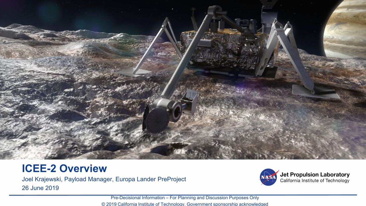
ICEE-2 OverviewJoel Krajewski, Payload Manager, Europa Lander PreProject26 June 2019
Pre-Decisional Information – For Planning and Discussion Purposes Only© 2019 California Institute of Technology. Government sponsorship acknowledged

ICEE-2 Program
• Award Date: 8 Feb 2019 to 14 awardees• Planned execution duration: 2 years• Deliverables
– Biannual: Briefings via telecon with NASA program managers– End of Year 1: Report on detailed spacecraft accommodation– End of ICEE-2 Task: Final Report (< 10 pages); Final Briefing at NASA HQ
1

ICEE-2 Goals from ROSES Call• “The goal of the program is to advance both the technical readiness and
spacecraft accommodation of instruments and the sampling system for a potential future Europa lander mission … to TRL 6 in the 2021/2022 timeframe.”
• Expected Instrument Technology Advancement Activities:– “Evolve this path [to TRL6] into a detailed technology development plan and begin executing it.”– “Developing requirements and flowing them down to the subsystem level and across to the spacecraft”– “Developing the instrument architecture; conducting acquisition planning”– “Completing heritage assessment; conducting performance, cost, and risk trades”– “Identifying and mitigating development and programmatic risks”– “Initiating engineering development activities; creating preliminary system-level designs”– “Developing time-phased cost and schedule estimates”
• Expected Spacecraft Accommodation Activities:– “close interaction (including face to face) between the NASA-JPL pre-project lander study team and
ICEE 2 selectees. “– “collaborative discussions of issues and solutions regarding instruments, the sample acquisition and
delivery system, and the landed element”2

3
Pre-Project Gains from ICEE-2
ICEE-2 Task AreaPriority order
Pre-Project interest
Sample Analysis InstrumentAccommodation
1) Refine driving requirements on delivered sample, e.g., minimum volume, thermal constraints, etc.
2) Develop viable sample transfer concepts and address associated Lander accommodation (e.g., thermal)
3) Assess range of desired sample processing and associated TRL level; Identify possible commonality across instrument types; Reassess plan for implementation responsibility
Autonomy Develop instrument capabilities driven buy short mission duration, especially autonomous sampling instrument checkouts/calibrations
Geophone Accommodation
Develop requirements for minimization of both Europan seismic signal attenuation and self-generated Lander noise
CameraAccommodation
Evaluate pros/cons of current baseline, which levies engineering requirements/constraints on Science cameras (i.e., cameras mounted to HGA, imaging of sampling hardware, etc)
Planning Refine assumptions regarding development schedule

ICEE-2 Awardees
4

ICEE-2 – PreProject Rules of Engagement• HQ encourages open exchange with the PreProject, and the process will be a mix of
– Awardee-wide discussions– Periodic Telecons between Individual Awardees and Pre-Project– Site-visits at Individual Awardees if specifically useful– Internal Pre-Project Analyses– Fully public workshops
• NASA HQ Rep (Schulte, Salute) is CC’d on email exchanges and invited to telecons
• JPL PreProject establishes Non-Disclosure Agreements with all PI’s who desire one
• JPL ICEE-2 teams are treated with the same constraints as non-JPL ICEE-2 teams
• Any additional Pre-Project technical material will be posted to a PreProject public website– Motivation: maintain level playing field for possible future AO
5

Payload Accommodation ResourcesNo changes to relative to the Draft PIP
6
Change since draft PIP
NoneNone – see later chartNone – see later chartNone
None
None
None
NoneNone
None
None
None
Expect ICEE-2 results may suggest refinements

Instrument Technical Resource allocations and Interfaces
• Draft PIP posted with ICEE-2 call remains the project’s baseline• Default policy is to retain the original allocations and interfaces
described in draft PIP.– i.e., Treat any deviation needed by a given ICEE-2 team’s as an instrument-unique
accommodation “cost”
• Specific draft PIP clarifications / refinements include: – Augmentation to Power interface requirements– Maximum Instrument length in Vault– Camera Heads on HGA:
• Max length and stowed orientation• radiation-shielding from HGA• flexibility in camera head housing
– Assessment of 2-meter external cable length assumption– Vault Temperature during Cruise and Surface Phases
7

Power Interface Requirements – Augmentation in BLUE ITALICS
• Information regarding Power Interface (Draft PIP Section 3.8.1): – 28V bus with a nominal range of 24-36V (operational range) at the connector
interface– All instruments need to tolerate any voltage 0-40V (survival range)– Lander provides 2A channels and a limited number of 5A channels
• Instrument can draw 100% of channel rated current during nominal operations (peak and average)
• Instrument can draw 200% of rated current for up to 80ms at turn on (INRUSH)• No spec available on ripple at this time
– A 10A channel can be provided by ganging 2x 5A switches– Single-point ground (SPG) system; primary power is kept isolated (typically
> 1 MOhm, for both the active and return)– Instrument provides all its own secondary voltage conversion with the
secondary returns tied to chassis8

Payload Volume Allocation
9
- Overall volume allocation remains the same
- Suballocation per instrument is notional only
- Shapes of notional suballocation are not strict
- ICEE-2 teams should propose volume shapes that are most natural to instrument design, improve ease of assembly/disassembly, etc.;
- PreProject will identify if/when a proposed shape is inherently un-accommodatable
Maximum Instrument Length in Vault
10
• As noted in ICEE-2 Kickoff, the individual instrument volumes shown in draft PIP Figure 3-1 are notional only - The overall collective instrument volume is a constraint
• Configuration of Flight System components and instruments within the Lander Vault can be rearranged to adapt to individual instrument form-factors
• The maximum length for a “long-skinny” instrument that can be accommodated in the Lander Vault without incurring Vault growth is 85 cm.– External Lander Vault dimension is 1 meter; 15cm allows for vault wall thickness,
mounting brackets, cabling access, etc.

Camera Head on HGA: Max Length and stowed orientation
11
Baseline: Camera Head Face Up for LandingLens-mounted deployable covers advisable
Max Camera Head Height= 10cm(Draft PIP WAS 8.1cm)Limited by Descent Stage hardware
Max Camera Head Height= 6cm(Draft PIP WAS 8.1cm)Limited by Lander Deck hardware
Alternative: Camera Head Faces Down for LandingEnables deck-mounted lens covers that disengage with HGA elevation actuation

Rationale for Cable Length assumption for externally-mounted hardware
12
HGA / Camera
Twist Capsules
Camera Heads mounted ~ 0.7m above Lander deckRequire cables at least 1.5m length to reach vault interior Including service loops and Az and EL joint twist capsules.
Draft PIP paragraph 3.3.1 specified 2.0 meter lengthTo enable flexibility in Camera electronics Placement
By comparison MSL Cameras on mast ~ 1 meter above deck required 3.7m flex cable to reach Camera electronics
Notional Camera Cable Routing

Additional Information on draft PIP Figure 2-10 relevant to Camera Heads
13
Stereo Cameras mounted to HGA; Shown mounted separately but both could
be in a single housing
High Gain AntennaProvides 4mm-equivalent Aluminum shielding on 1
side for Camera heads

Vault Temperature During Cruise
• Expect Vault to transition to steady state of ~ - 10 C within a couple days after launch
• ~ -10C vault temperature is expected to be maintained until < 1 day prior to Landing.
• Landing Day temperature transient up to max operating range of +50 C– Hardware required for DDL will be powered on and dumping
heat into vault
14

15
Lander Thermal BalanceNeed to account for Instrument heat loss to Environment
• Europa Lander makes use of battery, instrument, and avionics waste heat to maintain thermal balance
• To date, all instrument power allocations are assumed to be recaptured as waste heat into vault
• For Instruments with external heat loss:– Needs to be accounted for within
Instrument power/energy usage estimates
– Applies both during operation and non-operating conditions
Battery Pack
Battery Pack
Vault Wall(-40 C to + 50 C)
Instrument #1
Heat lost to environment
Heat recaptured
Instrument Heat Loss to Environment
AvionicsCamera Head Heater?
Radiator?Vent?
Assumption: 480 WHrExternal Dissipation
PossibleInstrument Heat Loss
Mechanisms
CameraHead
Allocation:1600 WHr
Tran
sfer
Doc
k
Instrument #2
Instrument #3

Vault Temperature bounds during Surface Phase
Landing
Post-landing Checkouts, imagingand data return
LanderSleep
Comm Activity Causes Temp Spikes1 hour near start of Earth in View window1 hour near end, and 1 hour in the middle
Instrument Activity during Earth in ViewPeriods in baseline scenario
Margin Time with Comm
Battery warmed atEOM to get max energy
Earth in view
Earth in view
Earth in view
Earth in view
Earth in view
Earth in view Earth View Periods
Vault temperate at Landing could be as high as 25C
Cold Case = Nominal CaseWith no sampling or instrument activity
Warm/Cold bounds could expand as design evolves, e.g., 1) If vault becomes thermally leakier than currently planned,
cool-down could happen faster than “Cold Case”2) If Ops scenario biases more Comm time early (e.g.,
expedite imaging return, improve anomaly response time) then cooldown would happen slower than “Warm Case”
First Sample Acquisition / Analysis
16

Wrap Up; PreProject Points of Contact
• JPL PreProject is excited to make progress on the unique challenges of instruments suitable for Europa Lander
• Joel Krajewski, Payload Manager primary point of contact– [email protected]– 818-354-5808 (office); 818-687-9829 (cell)
• Roger Gibbs, Project Manager– [email protected]– 818-354-6826 (office)
• Kevin Hand, Project Scientist– [email protected]– 818-354-9547 (office)
• Steve Lee, Flight System Manager– [email protected]– 818-393-6685 (office)
17Pre-Decisional Information – For Planning and Discussion Purposes Only