ices to build - scs technical report...
TRANSCRIPT

Using LSI processor bit-slices to builda PDP-11---a case study inmicrocomputer design*
by T. M. McWILIAAMS, S. H. FULLER, and W. H. SHERWOOD
Carnegie-Mellon University
Pittsburgh, Pennsylvania
ABSTRACT the Intel 3000 bit-slices and that is microprogrammed toemulate the PDP-I ! computer architecture. _'z* The purpose
In this article we give the design and evaluation of,the of this project was to investigate the assertions of semicon-CMU-I 1: a fully operational implementation of the PDP-I 1 ductor manufacturers that their LSI bit-slices would in fact
computer architecture built with Intel 3000 Schottky bipolar simplify the design and construction of processors.microcomputer bit-slices. This pro.iect was initiated to test Rather than specify a new architecture (i.e., instructionin detail the claims that LSI processor bit-slices simplify the set) for this experiment in processor design, we decided todesign ot" microprogrammed processors. The CMU-II exe- reimplement an established computer architecture: thecures approximately 240,000 instructions per second, which PDP-I i. We chose the PDP-I i architecture fer several
is about 63 percent the speed of the PDP-11/40 and twice reasons. Using an existing and well-known architecturethe speed of the LSI-I !. would allow others to more easily evaluate the results of
We explore in some detail the additional logic that was our experiment and kept us from consciously or uncon-added to enable the lntel 3000 circuits to emulate the PDP- sciously tailoring the processor architecture to fit the capa-11 instruction set. We specified full DEC Unibus compati- bilities and idiosyncrasies of the LSI bit-slices. Another
bility_ and 29 percent of the integrated circuits used to reason is that PDP-i t's are in extensive use at Carnegie-implement the CMU-II were required to provide buffeting Mellon Univ. in a wide variety of applications and, if ourand control of the Unibus. The other main sources of experiment was successful, the processor could be put toinefficiency were the lack of arithmetic overtlow logic in work on any one of several practical tasks. It was thisthe bit-slices and the organization of the microinstruction second reason that helped establish a critetia that proved tocontrol store. We show how improved LSI circuits in this be critical: we demanded that the processor we constructedarea can substantially reduce the size (and cost) of the support the standard DEC Unibus _ that is common to allprocessor. PDP-i l's except the LSI-1 !. Finally, the PDP-I 1 architec-
The set of design aids currently available at Carnegie- ture is an unusually good test of the capabilities of a bit-Mellon University was of critical assistance in this project slice circuit family because it is a relatively completeand we include a critique of our use of these design aids to architecture with numerous addressing modes and instruc-
show their utility in prototype design eftorts, tion formats. . _,_t.._t_'_. T_: F:Tz=_:7:,!7_'_n the next secttorbwltla a description of
the design of the CM U-ll processor. We then discuss theINTRODUCTION performance, cost and implementation difficulties uncov-
ered during the design and testing of the machine. In
Several semiconductor manufacturers have recently devel- addition to the evaluation of the LSI bit-slice circuits foroped high speed LSI circuits that are designed to simplify general-purpose processors, we are interested in the prob-the construction of microprogrammed processors and de- lems of computer design in general. For this reason, a fairlyvice controllers. These integrated circuits are called "'bit- complete set of digital design automation aids are availableslices" because they implement t_o or four bits of the at Carnegie-Mellon University: an interactive drawingregisters, arithmetic units, and primary data paths of a package that generates engineering drawings, wire-lists, and
processor. This article presents the design and evahmtion of aids in engineering changes; a digital simulation s3,stcm thatthe processor built at Carnegie-Mellon University that uses is interfaced to the drawing system; and microprogram
assemblers. A later section of this paper reviews our* This v,,:;-k was pa;-tially supported by ;he Advanced Research Projects
Agency (ARPA) of the Department of Defense under contract F44620-73-C- * We gratefully ackno_._,ledge the d_nati__,n of 30f'_) microcomputer sets by
0074, monitoi'ed by the Air Force Office of Scientific Research. both lntel and Signetics Corp_rations.
967

908 National Computer Cofffe_ence, 1977
-experietlces with these design aids and we draw some eight 3002's have been used in the CM[5-1 I. Although notconclusions concerning the process of designing z,nd debug- explicitly shown in Figure !, the 3003 car,'y-lookaheadging prototypes of digital systems built with LSI circuits, circuit is al,io u,.,ed. \Vith the 3003, the 3002 avlay is cap::ble
of cycling through operations every 150 us. [lowever, other
delays in the cl_ck and control part dictate that the CMU-ORGANIZATION OF THE CMU-II II has a 200 esec micro-cycle time. The eight general-
purpose ,_,orking registers of the PDP-II architecture canFigure 1 is a register-transfer level diagram of the CMU- be kept in the register scratchpad on the 3002's, and the
11 microprogrammable processor. The processor's compo- three remaining internal registe,'s, R8, R9, and T arenents are arranged in the diagram into three sections: the sufficient for source and destination operand computationsdatapart, controlpart, and Unibtts interface. We were able as well as other intermediate results. The Program Statusto build the entire processor on a single board and Figure 2 (PS) and Instruction Register (IR) were not possible tois a top view of the CMU-I 1. _lllocate within the 3002's without a severe loss in perform-
ance.
The relatively generous number of input and output linesThe data paths and working registers of the 3002's are used to good advantage. The D(15 • 0)
and A(15 • 0) buses feed the Unibus Data and AddressThe data part of the processor is designed around the
lines respectively. In addition, the D bus allowed access to3002 (central processing element) bit-slice. A single 3002
the extra data paths necessary to include the PS registercircuit implements a 2-bit slice of the data paths and hence
and to facilitate the byte swap operation needed by many of
Figure i--Register transfer level diagram

A Case Study in MicroconlpUtCr De..,ign 96:9
[i:r !II ?lltlililt:i[ !ii l
A / .......
Figure 2----CMU-Ii processor board t _qi_, %_
T '_ .....the PDP-I I's instructio he M(15 • 0) bus is used as the
principle data input bus. The Function bus, F(6 • 0), - Figure3--CMU-llsystemwithassociatedPDP-IIspecifies both the operation to be performed by the arith-metic/logic unit as well as the selection of the register in thescratchpad to be involved in the operation. The K(15 • 0)bus is used to input masks or constants from the microin- register is defined as primary memory location 177776 in
struction. The 3000 circuit set makes frequent use of the K the PDP-I 1 architecture requires special logic to load and
lines to specify masks (usually all zeros or all ones) that ,,_ store the PS.effectively extend the operation code on the Function bus..._
t__. Interface to the unibus
Control partA significant fraction of the components of the CMU-I 1
The control part of the CMU-ll uses the 3001 Micropro- _ are devoted to the support of the Unibus. Given thegram Control Unit and a 512 word control store** with 32 _ demanding electrical requirements of the Unibus, the tri-
bit microinstructions. Figure 4 shows the format of the _ state A, D, and M lines of the 3002 array could not bemicroinstruction and Table I briefly describes the function directly attached to the Unibus. Instead, separate trans-of each of the fields. A microinstruction buffer register was _ ceiver packages had to be used to provide this buffering.included in the design to allow the overlap of the fetch of ._ Due to the asynchronous operation of the Unibus andthe next microinstruction with the execution of the current _ interrupt and non-processor requests (i.e., direct-memory
microinstruction which is a common technique to improve _ access request via the Unibus) it was not practical to drivethe Unibus dh'ectly from fields in the microinstruction,
the performance of microprogrammed processors. "__, a bus control and timing section_added-i0 the -'_'_
The "'next-address logic" of the 3001 has been aug- %i processor. The rest of the processor interfaces to thismented by additional microbranch control logic external tothe 3001. This external logic uses the contents of the o| control unit via the UC(7 : 0) field in the microinstruc-Instruction Register, the condition codes in the PS, and the _'_1 tion. See Table I for a description of the functions of thePLA field from the microinstruction register to determine - subfields within UC(7 : 0).the AC(6 " 0) lines to input to the 3001.
The other major section of control logic that had to be Console functionsadded to the design was the Processor Status logic tocontrol the setting of the 4-bit condition code in the PS
In place of a standard front panel, the CM U- I 1 has frontregister and control access It) the PS. _ fac_ the PS
panel functions acces,;ible from a standard teletype :tt-
_-_ _1_ tached to the Unibus. Memory lock,lions can be examined
In order to expedite the debugging of the microprogram for th/CMU-I I, and loaded by typing the octal address followed by a slash.v,e built a fast, simple writable control store for the CMU- I I. 45_ec access The current value is displayed _tlltt a new value may betime. 1024bit RAM packages were used to assure a v,ritablecontrol store as entered if desired, followed by a c[tl'ria_e return. Thefast as the final ROM control store. The wfitablecontrol store is interlhcedto a Unibus (of a PDP-II other than the CMU-II) for initial loading of processor may ztlso be st_lrted and continued fl'om themicroprograms. Figure 3 shows the CMU-II interfaced to the supporting teletype_and there is a halt switch on the front panel whichPDP-11and writable control store. Catlses the machine to lettlrfl to tile console microprogrztm.

970 National Computer (7old_crcncc. 1977
31 P2_ 24 1_ 7 14 "3 11 lk3 9 2 1 0
1AC( 6 :P_> F< 6 :0> gO< 3: _> PLA< 2 :_,> K< S:' K< 7 :C)* l_,_S_I :G>
JL2_P CONTROL CPE CONTROL CA_P,Y CONTROL SPECIAL _L,',ANCH UPPER BITS 9 BiT CONSTF4NT FOR C_ES I-_IC£O _40RO
CONTFCOL CONSTANT J SELECTOR
9 8 7 6 B 4 _ 2
RP( I :0> C( I :0>
UC<7:8;,, UNIBUS CONTROL:
REGISTER EXTENDED GET BUS PF4usE CHECK _0R'D C1, COADDF--':-S S MICROINSTR CONTROL
9 s 7 6 -q 3 2
PS(7:O), PS LOGIC CONTROL: SSS SDS CCTP(I:O> SCCTR(2:O)
SET SOURCE SET DESTINATION C CONTROL SHIFT SET PSSIGN SIC,N COl',TR'DL FEOISTER
, _ ......
Figure 4---Microinstruction format
This use of a teletype for a console is similar to the console several representative instruction times and by running a
teletype used by the LSI-I 1.4 In order to make it easier to set of benchmarks on the machine. Evaluating the cost of
maintain the processor, we have added a microprocessor the CMU-II has been more difficult. Rather than try to
console which displays the microprogram address and al- compare the price of existing PDP-I i implementations with
lows the microprocessor to be single-stepped. The micro- the cost of the CMU-I 1, we chose instead to compare it
console proved invaluable for debugging the prototype with other PDP-I I's with respect to circuit complexity. The
processor, other significant costs, i.e., development costs, are di-cusssed in a later section.
EVALUATION OF CMU- I I DESIGN
Performance of the CMU-i 1
The critical questions to be asked about this design
concern cost and performance. It has been fairly easy to The CMU-I I runs at a microinstruction cycle time of 200
evaluate the performance of the CMU-II by looking at nsec. The specifications for the lntei 3000 microcomputer
TABLE I--Description of Microinstruction Fields
MWS(i : 0):= MI(i : 0) Mi"ro Instru,'tion Selector. Specifies if MI(9 : 2) should define a constant, unibuscontrol, or PS control.
K(8 : 0) := Mi(10 : 2) Liter,d. K(7 : 0) is a byte constant used by the least significant byte ofthe K input linesof the 3002 array. K(8) is extended to feed the most significant byte of the K input lines.
UC(7 : 0):= MI(9 : 2) Unibus ControlUC(I : 0) CI, CO Control. Specified the CI and CO lines on the Unibus.UC(2) Check Word. Tests whether a word address is specified in Unibus operation.UC(3) Pa,se. Halt processor clock until completion of Unibus operation.UC(4) Get Bus. Request access of Unibus for a data transfer.UC(5) Extended Micro Instruction (?ode. If set, defines alternate meaning for PI.A(2 : 0).UC(7 : 6) Rt,gister Addresx. Specified which input register address multiplexor should be u_ed.
PS(7 : 0):= Ml(9 : 2) Processor Status ControlPS(0) Set PS Register. Controls loading of PS.PS(3 : 1) Shift ControlPS(5 : 4) Carry ControlPS(6) Set Destination Sign. Controls latching of sign of destination operand in flag external to
3002's.
PS(7_ Sct Source Si,vn. Analogous to PS(6>.
PLA(2 : 0) := MI(13 : 11) Special Branch Control. Used by microbranch logic to tell which fields of IR and PS toexamine tbr branch conditions.
FC(3 : 0) := MI(17 : 14) _.i MCU l-Tag Control. Control.., testing and setting of flags in 31,)01(MCU).F(6 : 0) := M!(24 : 18) _'_Control. Drives Function Bus of 3002 (CPE) array.
AC(6 : O) := Ml(31 : 25) _ Address ('ontro/. Connected directly to the AC(6 : 0) bus of the 3(101(MCU). This is theone field of the mio'o iastructkm not buffered in the micro instruction register. (The
bticroprogram Address Register internal to the MCU performs the buffenng function.)

t
A Case Study in Microcomputer Design 971 _!
faniily state that it is possible to build a 16 bit minicomputer TAm.E ll--E_ecuti,m "l'ime,, t,f C,m_mon lnstruction_
with a 150 nsec. cycle time. However, given our objective t_asicexecutioJ_time (microsecond,,!tO design as cost-effective an implementation as possible,we avoided the sensitive and complex timing circuits that Instruction I.Sl-ll ('MU-II Pl}P-ll:4(I
would be required to approach a 150 nsec. cycle time. MOV 3.50 206 0.')uIf we had used clocks with sufficient buffering and pulse c_I_' 3.50 2 19 0.99
shaping, a worst-case analysis shows that with the particu- ASl. 3.85 2.46 0.99ADD 2.46 3.85 0.99
lar IC packages used in the CMU-II, we could approach a BRX (branch) 3.50 2.82 1.76149 riser, cycle time with Intel 3000 packages and a 126 {no branch) 3.50 1.48 1.40
nsec. cycle time with Signetic_version of the 3000 set. We JSR _,.40 4.39 2.94
have in fact replaced the lntel 3000 circuits with theSignetics circuits and although the CMU-II continues torun reliably at 200 nsec., we cannot reduce the cycle timebelow 200 nsec.: the critical path is in the control part ;rodnot the 3002 array, symbol table. This benchmark makes extensive use of the
Tables II and III show the execution time for six of the byte and compare features in the instruction set.
most frequently executed instructions and the eight ad-Table IV shows the execution times on the LSI-I I, CMU-
dressing modes of the PDP-I i. The instructions in Table IIIi, and PDP-I 1/40 fi_r each of the lkmr benchmarks. From
assume a register-to-register operation (i.e., a source andthese results we see the CMU-i l is approximately twice as
destination mode of 0). Table III shows the additional timefast as the LSI-I 1 and 63 percent of the speed of the PDP-that is added to the instruction execution time for the! 1/40. As expected, there is a moderate amount of variation
various source addressing modes.* The destination modein the relative performance of the three machines for the
times are about the same as the given source mode times.different benchmarks. The two dominant effects that can be
In order to measure the performance of the CMU-i I forseen in Table IV are that the PDP-11/40 design has optim-
various instruction mixes, several benchmarks were col-ized register-to-register operations more than either the
lected and run on the CMU-I 1, an LSI-I 1, and a PDP-I 1/LSI-li or the CMU-II (as demonstrated in the partial
40. Four benchmarks were collected that attempt to span a differential equation benchmark). Byte operations m'e morereasonable range of applications common to minicompu- efficiently performed in the CMU-II because of its byte-ters:
swap data path provided by the D and I buses. The last line
Quicksort. This is a program that uses Hoare's quicksort in Table IV is the data published by O'Loughlin _ in anprocedure to sort a set of 16 bit integers. The benchmark article comparing the different DEC PDP-I I implementa-tions.also includes a pseudorandom number generator to pro-vide the initial data. It is mildly disappointing that the CMU-il, built with
Schottky TTL bit-slices could not equal the performance ofTrigonometric Functions. A set of trigonometric, float- the PDP-11/40, built with standard TTL circuits. The nexting-point routines. We do not assume the existence of a
two sections will examine in detail where performance wasfloating point option on any of'the processors and hencethis benchmark heavily exercises software floating point lost (and gained) in the CMU-II design. Before continuing
with this review of the design, we turn to a brief discussionemulation routines, of the cost of the CMU-11.
Partial Differential Equations. A program that uses a A principle objective of the 3000 microcomputer bit-slicestraightforward iterative relaxation technique to solve apartial differential equation over a two-dimensional packages is to simplify the design of processors like the
CMU-II. Table V is a summary of the complexity (meas-space. Fixed-point values are used. ured in integrated circuits) of the CblU-I !. There are twoText Searching. Searches an input string for names in a columns in Table IV. A simple count of the number of
i" In particular, the times in Table lll are the sour_:e addresses modes time integrated circuit packages used in the CMU-I I_ and afor the CMU-! I as measured on the BIS instruction. Addressing times on the column that converts the design to "16-pin eqmvalent"other instructions are similar to the BIS times, packages (a measure of the size of the design in a standard
TABLE lll--Execulion Times for the Source Addressing M_des
Addressing mtxle LSI-I I CM U-! I PDP-11/40
0: Register 0.00 p.sec 0.00/xsec 0.00 ,u._ec
I: Register Deferred !.40 1.21 0.782: Autoincrement 1.40 0.64 0.84
3: Autoincrement Deferred 3.50 1.91 1.74
4: Autodecrement 2.10 1.00 0.84
5: Autodecrement Deferred 4.20 2.28 1.74
6: Indexed 4.20 1.78 1.46
7: Indexed Deferred 6.30 2.99 2.36

National Computer Conference, 1977 i972t
f
TABLE IV--Pc.ffornlance o1"CMLyl I Relative to Other PDP-ll's
f/: Execution times relative to PDP-I 1/40"
Benchmarks LSI-II / 11/10 11/20 CMU-IX iti40 11/45s¢
,,
Qtlicksort 2.88 (366) / 1.48 1188} 1.0 (127)
Partial Diff. Eqn. 3.48 (268) / 1.75 (135) !.0 (77)
q'lig. Functions 3.36 (111_¢ 4" 1.57 i52) 1.0 (33)Text Searching 2.76 (2_WJ 1.45 11071 1.0 (74)
s'
Average 3._._ -- -- 1.6 i.0 --
O'Loughlin's Data -- 2.32 1.85 -- 1.0 0.91
* Numbers in parentheses are the absolute run times in seconds for the benchmarks.
'k
unit). Table VII gives a breakdown of the actual cost of the of _,_ microprograms. Table VI gives the size of micropro-CMU-II at January, 1976 prices, grams for several PDP-ll processors. It is somewhat sur-
It is surprising that less than 20 percent of the design is prising that the CMU-I ! uses fewer bits in its control storenow in the data part of the processor: the part of the than any of the other processors except the LSI-I 1. This isprocessor largely implemented with the LSI bit-slices. A in large part due to the fact the 11/10. 11/40, and I !/45 uselarger part of the design, 29 percent, is needed just to MSI arithmetic/logic packages that did not have as useful ainterface to the PDP-I 1 Unibus. set of primitive operations as the 3002 ALU.
In order to put the 144 package complexity of the CMU-11 in perspective, the IC package counts for other PDP- 11's I0 _ I _ ,_are: PDP-I 1t10--203 packages; PDP-I 1/40----417;and PDP- SOME PITFALLS F,_;'.3_D ',,_-_,_P_.U,".,'-;;f;_i;i-;G_--ifit-z11/45--696. The LSI-ll is able to implement the basic _ the.___.3000BIT-SLICES. _tlldb. o._._ _ae,,,t_e_,T_t_,,,_."processor in 42 packages but does not interface to a /!_.P,_ _9¢_Unibus. It is clear that the bit-slices do not approach the Since the CMU-II project was started, a number ofeconomy of the Western Digital NMOS microcomputer different bit-slice chips have become available whose orga-circuits which were specifically designed to emulate thePDP- 1I.
Data
" Another measure- .... ............. -. -1.... _-] _. ]
_of how.efficiently the CMU-11 microprocessor is - ' --able to emulate the PDP-11 architecture is given by the size .....................
TABLE V_Integrated Circuit Statistics
No. 16 pill s..... _, p.,a ........ :' ";_V___.-.
Processor component packages packi_ges _ _:0-__,
PS and Instruction Registers 6 6 ---Misc. 4 5
CONTROL PART .Tac......Control Store ROMs 8 8
Micro Instruction Register 10 103001 (MCU) I 3
Microbranch logic 26 27
PS Control 16 16 ......./_l.__._x_
subtotal 79 82 (52%)
,UNIBUS INTERFACE | __
Bus 'Iranceivers and lnverters 19 19 [ ______J ......... ,
Unibus Control 28 28 c_[._ .,n,,,_ ....
1subtotal 47 47 (29%) _
<15:0.
Total i44 i60Figure 5--The Am2901_A 4 bit bipolar microprocessor slice

A Case Study in Microcolnpllter Design 973
TABLE Vl----CostBreakdown for CMU-II
Price..,
Components Single Units Quantitie,,of I(.,q)_--
LSI Microcomputer parts $207 $125(intel 3001,31_02's,31,q)3) 1184)*
PROMS
(3601, 3602,3604,745168) 204 136SSI/MSI Pal-ts 179 158
Integrated Circuit Subtotal 590 419Augur Wirewrap Board 379 (use printed circuit)Wirewrapping 107
Total $1076
* Signetics prices
nizations are significantly different from the 3000 circuits to use separate bus drivers and receivers. Once external
and which provide an interesting contrast. Two of the more bus drivers are added_the advantage of the two outputinteresting bit-slice chips are the Advanced Micro Devices buses for the address and data is minimal, because anAm2901 and the Monolithic Memories Inc. MMI6701. equivalent external address register can be loaded as l:ast asThese bit-slice chips have a very similar data path organiza- the existing internal address register and combination bus
tion with only minor differences, the Am2901 being the drivers/latches are available (e.g., Am2905). The savingsfaster device. Because of the similarity of these devices, we realized by having three input buses is the cost of adding
will limit the discussion here to the Am2901, but all of the eight dual 4-to-! line multiplexer chips at the inp_ut to themicroinstruction sequences discussed will work on both bit- bit-slice chips. The saving achiev_ive buses in _"f_slice sets. the 3000 bit-slices over the A!l12901's single input and
The basic data path of the Am2901 is shown in Figure 5. single output bus is 12 16-pin circuits, plus three bits in the
The chip contains a register file of 16 4-bit accumulators cont_ol store (two for the select lines on the inpt_t multi-and an accumulator extension register, the Q register. In plexer, and one to control loading of the address register).one microinstruction, two operands can be read out of theregister file, passed through the AI,U, the result
shifted left or right, and written back into the Arithmetic overflow with the 3000
register file. In parallel with this, there is an addressingmode which controls the RAM and Q shifters allowing the One of the biggest problems encountered with the PDP-output of the ALU and the Q register to be right shifted 11 implementation using the 3000 bit-slice was detection ofsimultaneously, which is well suited for the inner loop of arithmetic overflow. The 3000 bit-slice has no overflowmultiply or divide instructions, output and the signals needed to directly detect overflow
are not available at the external pin connections. Thisresults in considerable overhead in emulating instructions ,, _,
I/0 Buses which must detect overflow (e.g., instructions that set the ll_ Vbit in the PS register of the PDP-i 1). The CMU-I i overflow
The main advantage of the 3000 bit-slice over the Am2901 handling was implemented with two external flip-flopsis its five fully parallel data buses for transferring data in which contain the signs of the source and destination
and out of the chip. It has two tri-state output buses (the A operands. After an instruction is fetched)its operatlds areand D buses) and three input buses (M, I, and K). If the first fetched either from memory or from the register stack,minicomputer to be emulated has IR thirly short 1/O and and are put in the source and destination registers withinmemory buses, the 3000 buses can directly drive them, the 3002. As the eperands are fetched, the source andresulting in a substantial savings in bus driver packages. In destination flip-flops are set to the signs of the operands.the CMU-I 1, we needed to drive a DEC Unibus, so we had When an instruction is executed the overflow logic can use
TABLE VII--PDP-I! ControlStore Sizes
LS1-Ii PSP-I1/10" !A_//_CMU-II PDP-11/40" PDP-11!45"
22bits x 512words 40bits × 239 32bits x 287words 56 bits × 251 64 bits x 256(includes console) words (without con_ole) _ords words
414words (with console)
* [O'Loughlin 1975]

974 National Computer (?onfcrcnce, 1977
the signs of the operands and result to detect over_qow. This . possible because the Am2901 ill one microinstruction cantech_ique works well when the operands are from memory, add two general registers together, shifting the result andbut really slows down the register-to-register operations the accumulator extension register right one bit. A similarbecause the operands have to be moved to the AC so their speedup also occurs for division.signs can be latched in the external source and destinationsign flip-flops.
_, r'_"_ The ,_c_uence of instructions needed to emulate a regis- ADDII'IONAL COMMENTS ON THE CMU-II DESIGN
_-_,a., tcr-to-reg_ster_ts shown in Figure 6. The first instruction inthe sequence loads the source operand into the AC, in The 3000 microcomputer circuits are not the only m'ea inorder to get its sign out of the chip. The next instruction which to look for improvements in the CMU-II design. Aspecifies tbr the source sign flip-flop to be set to the sign of ma.ior source of complexity was the Unibus interface (29 -the AC, and to store the AC into the T register. The percent of processor's packages). The 3002 bit-slices pro-f_ two instructions load the destination operand into vide tri-state drivers for their A and D lines and if Unibus
,, i,_ ....
i,-'_,., _/ the AC and set the destmatlon sign flip-flop. The last two compatibility is not essential, the outputs from the 3002_"_'_,_\,,'_ instructions do the add and store the result back in the circuits could directly drive a memory and 1/O bus of_,..)' __ _ destination register. Because of the multzple use of fields in moderate size. If synchronous operation of the memory bus
_(., "_ the microinstruction it is not possible to specify that a is adequate, further simplification of the bus interfaceregister address comes from the instruction register in the section of the processor is possible.same microin_truction that sets zither the source sign or A number of integrated circuit packages are now avail-destination sign flip-flops, or which sets the condition able that could help simpiify the design of the control partcodes. If the microprocessor were to be redesigned to allow of the processor. Most significantly, 4K bit PROM's appro-this, the register-to-register add could be done in three priate for use in the control store m'e now available withrather than six microinstructions with the 3000 chips, internal latches for use as a microinstruction buffer. This
However, we wquld pay for this performs, nee improvement would eliminate the need for the separate latches used in
by_ us_t'_ wider mlcrotnstruchon._e Am2901 the CMU-ll s microinstruction register. A related optimi-_ag _ 7r:--'_!,_-eyt_n:_-_-w____-t__-__ _ overflow detect output on zation to the CMU-II would be to move from the partly
the chip_m_d, the register-to-register add can be done with encoded microinstruction format of the CMU-! l to a wider,only one microinstruction, resulting in a considerable speed fully horizontal format. The random logic needed to decode
increase over the 3000 chilJ" an encoded microinstruction is simply more expensive thanthe extra bits in the control store needed for the horizontalformat.
Example of a multiply instruction We attempted to use programmable logic arntys (PLA's)in our initial design, but converted to ROM's when the
The inner loop of a 16 bit integer multiply instruction on PLA's we were designing with were dicontinued. By now,the 3000 chips requires either three or six microinstruc- however, several useful PI,A's are readily available. Fortions, depending on whether that cycle is a double register example, the Signetics FPLA, with its 16 inputs, is wellshift and add, or just a shift. The high order word of the suited to the decoding of PDP-Ii instructions.
product is stored in the AC register, and the low order word Below are the gains that might be expected in a secondis stored in the T register. Initially, AC is zero, and T holds iteration of the CMU-! I design:the multiplicand. For each iteration of the multiply, theloop count is decremented and if the low order bit of the T CMU-II 160 IC packagesregister is a 1, then the multiplier is added into the AC and Non-Unibus Design 128the AC and T registers are shifted right. Because the 3000 Integrated ROM/MIR and horizontal 113cannot add a register to the AC without also putting the microinstruction formatresult in the register, it takes three microinstructions to Convert to Am2900 circuits 95
perform the inner loop addition.For the Am2901, the inner loop of the multiply can be
done,-in two microinstructions with no external loop
counter, and in one with an external counter. This is COMPUTER-AIDED DESIGN TOOLS
_i_ Aside from freeing the designer of bookkeeping andILR SR ter
SDR T, !_? and SE17Source Sign clerical tasks, the main advantage of any design automationILR DR f ;_¢._-'-DcstinationRegister system is its inherent ability t() maintain correct and con-NOP SE'I_S ;SET_'-Destim_tionSign sistent documentation (prints _tnd wirelists) and the reducedALR T, SETCC ;AC=AC+T and SET Condition turnaround time for design iterations. The tact that the total
CtKles
SDR DR, 1 ;Destination Regist_C prototype development time for the CMU-Ii was 39 (40Figure f----Microsequenceexample: Register-to-register add frith overflow hours) m;-m-weeks is an example of the savings possible
detect with even modest design automation aids.

A Case Study in Microc¢_mplJterDesign 975
Description offttcilities used at CMU grams to extract int\)rmation for wirclists and cros_-refcr-
ence tables from its data base. Incorpor,tted in the sy.,,temThe Stanford University Drawing System was used to are libraries of integrated circuit definitions _xhich contain
enter the schematic print set with a graphic_ display termi- not only the pictorial representation of the g_ttes but ,tlso
hal. The drawing package include.,i a set of satellite pro- pin section intbvmation and some loading data. H;_rd copse
interactive commands
to simulator
,, . _
_ .........LogicI,-,+y emI I
input logic
design TimingDiagrams
Registeras and
SignalTraces
logic prints wirewrap lists, T
loading analyses I
Mi_p_og_mrlI
.... _?, =
Old Engineerin_
Wirewrap _ Charge /
List Orders /
Figure 7--CAD system at CMU
976 l_a(ioniil Computer Conference, 1977
prints were conveniently generated by an XGP (digitally An example of the worth of the computer aided designcontrolled Xerox Graphic Printer). The wirelist program system was when a major implementation change was madecan search the data base interactively fc,r specific informa- when several ROM's were incorporated into the design totion or produce complete tables of run lists, stuff lists, error replace a discontinued t)!.A _programmed logic array). ()urreports (wire-anding violations), and loading analyses, design aids were essential in effccting this change withinwhich all proved extremely helpful, four man-days. In order to recover so quickly from such a
The logic simulator used was SAGE (Simulation of m_r, sive wiring change, an ECO wrap/unwrap program wasAsynchronous Gate Elements), which is a four-state {0, 1, run using the old and new wirelists produced by thehigh impedance [tri-state buses], and undefined (initializa- drawing package. Thus, at all times during development,tion and uncertainty in delay patamett:rs)} gate-level simu- the processor rellected the exact connectivity of the printlator. It reads the data base directly from the output of the set.
Stanford Drawing system. This proved to be of utmost Several of the errors discovered on the real machine were
convenience, since it allowed a turnaround time in the timing errors that were not caught in the simulation debug-order of five minutes for print set corrections. SAGE has ging. These errors were not detected because the simulation
models in its libraries for the TTt. and Schottky families models did not consider the effects of loading on theand special routines were written by us to emulate the 3000 propog_,.:.ion delays and only maximum delays in all gatesmicrocomputer set. This allowed improvements in the eft'i- were used as an approximation to worst case conditions. In
ciency of the simulation execution. Macro facilities are also fact, if time had permitted, minimum and typical (Gaussianavailable for quickly defining MSI circuits from more basic distributed) parameters should also have been tested. How-
logic gates. The results of the simulations are in the form of ever, we again face a fundamental problem with simulationregister and signal reports and timing/trace diagrams, in that the computation time becomes excessive as different
sets of delays are simulated to find worst case conditions.
Debugging with the simulator
CONCLUDING COMMENTS
About 95 percent of the original design errors were
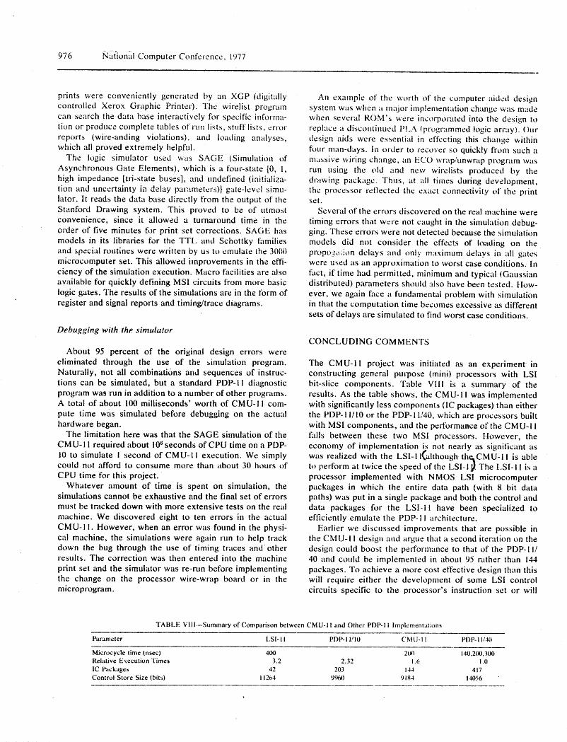
eliminated through the use of the aimulation program. The CMU-II project was initiated as an experiment inNaturally, not all combinations and sequences of instruc- constructing general purpose (mini) processors with LSItions can be simulated, but a standard PDP-il diagnostic bit-slice components. Table VIII is a summary of theprogram was run in addition to a number of other programs, results. As the table shows, the CMU-1 i was implementedA total of about 100 milliseconds' worth of CMU-I I corn- with significantly less components (1C packages) than eitherpate time was simulated before debugging on the actual the PDP-! !/10 or the PDP-I 1/40, which are processors builthardware began, with MSI components, and the performance of the CMU-I 1
The limitation here was that the SAGE simulation of the falls between these two MSI processors. Howeve,', theCMU-I i required about 106seconds of CPU time on a PDP- economy of implementation is not nearly as significant as
10 to simulate ! second of CMU-II execution. We simply was realized with the LSl-II(although th_CMU-II is ablecould not afford to consume more than about 30 hours of to perform at twice the speed of the LSI-I_ The [.SI-I ! is aCPU time for this project, processor implemented with NMOS LSI microcomputer
Whatever amount of time is spent on simulation, the packages in which the entire data path (with 8 bit datasimulations cannot be exhaustive and the final set of errors paths) was put in a single package and both the control and
must be tracked down with more extensive tests on the real data packages for the LSI-i 1 have been specialized tomachine. We discovered eight to ten errors in the actual efficiently emulate the PDP-II architecture.
CMU-I I. However, when an error was found in the physi- Earlier we discussed improvements that are possible incal machine, the simulations were again run to help track the CMU-I ! design and argue that a second iteration on thedown the bug through the use of timing traces and other design could boost the performance to that of the PDP-I I/results. The correction was then entered into the machine 40 and could be implemented in about 95 rather than 144print set and the simulator was re-run before implementing packages. To achieve a more cost effective design than thisthe change on the processor wire-wrap board or in the will require either the development of some LSI controlmicroprogram, circuits specific to the processor's instruction set or will
TABLE VIII--Summary of Comparisonbetween CMU-1! and Other PDP-! i Implementations
Parameter I.SI-i I PDP-I1/10 CMU-I I PDP-I 1/411
Microcycle time (nsec) 400 20t) 140,200,300Relative E _:ecutionTimes 3.2 2.32 1.6 1.0IC l_ackagen 42 203 144 417Control Store Size (bits) 1i264 9%0 9184 14056

A ('use Study it_ Microcomputer Design 977
provided in the LSI circuits. 4. LSI-IL, PDP-# #i03 Proce_'s_,r thmdbook, Digital Equipment Ct_rporation,Maynard, Mass., 1975.
5. O'[.oughlin, J. F., "'Microprogramming a Fixed Architecture Machine,"
I,lj;_tech St,te of the Art Rep_Jrt 23. Infolech Information l_imit._d.Maidenhead. t'nglatid. 1975, 205-224.
R E FE R E NC ES 6. A m2_a)O Bipohir Micropro_es _'or Circuits. Advanced Micro Devices. Inc.,Sunnyvale, California. 1975.
1. lntel Schottky Bipolar LSI Micro¢onlputer Set: 3001 Microprogram 7. Fuller, S. H.. T. McWilliams, and W. Sher,,,,ood, CMU-II Engineering
Control Unit, 3002, Control Progressive, Element, and 3003 Catrry Looka- Documentati,m. Dcpa_ment of Computer Science, Carnegie-Mellon I.Jni-head Generator. lntel Corporation, Santa Clara. California. 1975. versity, Pittsburgh. Pa.. 1976.
2. Introducing the Series 3000 Bipolar Microprocessor. Signetics Ctwpora- 8. PDP-I I/O5/IOL¢5/40 PrL)ces._or klandbook. Digital Equipment Corporation,tion, Sunnyvale, Calih_rnia, 1975. m:ty.qi.u-d, Ma_s., 1973.