ict network standards
TRANSCRIPT

ICT NETWORK STANDARDS
- POWER PROVISIONING
AUDIO VISUAL & NETWORK SERVICES
ICT NETWORK STANDARDS VERSION 2018-01
Deakin University CRICOS Provider Code: 00113B

Audio Visual & Network Services Page 1 ICT Network Standards Version 2018-01 deakin.edu.au
Deakin University CRICOS Provider Code: 00113B
Contents 1 Terms used in this document .......................................................................................................... 2 2 Contacts .......................................................................................................................................... 2 3 Scope of Document ......................................................................................................................... 3
3.1 Purpose ............................................................................................................................ 3 3.2 Document Access ............................................................................................................. 3 3.3 Associated Documents ..................................................................................................... 3 3.4 Document History ............................................................................................................ 4
4 Accountability ................................................................................................................................. 4 5 General Information ....................................................................................................................... 4
5.1 Approved Hardware ......................................................................................................... 4
6 Power Protection Selection ............................................................................................................. 5
6.1 UPS Capacity ..................................................................................................................... 5 6.2 Consolidation ................................................................................................................... 5 6.3 UPS Runtime ..................................................................................................................... 5
7 UPS Placement ................................................................................................................................ 5 8 Management and Security .............................................................................................................. 6 9 Power Calculations ......................................................................................................................... 6 10 Connection to Electrical Utility Services – Dual Power .................................................................... 6
10.1 Direct Mains Connection .................................................................................................. 6 10.2 UPS Connection ................................................................................................................ 6
11 Rack Mounting of PDUs ....................................................................... Error! Bookmark not defined.
11.1 UPS Power Distribution to Rack ....................................................................................... 7 11.2 Mains Power Distribution to Rack .................................................................................... 8 11.3 UPS Power Cable to Supply .............................................................................................. 8 11.4 Power Outlet Provision ...................................................... Error! Bookmark not defined. 11.5 Power Cable Management ................................................. Error! Bookmark not defined.
12 UPS Type ......................................................................................................................................... 9
12.1 In-Rack UPS ...................................................................................................................... 9 12.2 Standalone UPS ................................................................................................................ 9
13 UPS Management ......................................................................................................................... 11
13.1 Network Management Card and Ethernet Network Connection .................................. 11
14 Accessibility .................................................................................................................................. 11 Appendix A – Approved Hardware .............................................................. Error! Bookmark not defined.
Audio Visual & Network Services Page 2 ICT Network Standards Version 2018-01 deakin.edu.au
Deakin University CRICOS Provider Code: 00113B
1 Terms used in this document Word or Short-form Definition
AG1 FSD Lock numbering system
AVN Audio Visual and Networks Group
BAS Building Automation System
CM 1 General Communications room
CM 2 Building Gateway Communications room
CM 3 Distribution Communications room
CM 4 Core Communications room
Contractor Any consultant, installer, integrator, contractor or sub-contractor hired to provide products or services to Deakin
DeS Deakin eSolutions
FSD Facilities Service Division (Deprecated)
GPO General Purpose Outlet for distributing 240 VAC power
IPG Infrastructure and Property Group (Formerly Facilities)
LAN Local Area Network
Network Engineering Deakin eSolutions Network Engineering Team Leader or their delegate
PDU Power distribution Unit
PoE Power over Ethernet
RMS Room Management System
UPS Uninterruptable power supply
WAN Wide Area Network
2 Contacts A Network Engineering Representative will be assigned for all projects or tasks that impact the Deakin ICT network. This person shall be the first point of contact for all queries. If this person is not available to answer queries, the Deakin eSolutions Network Engineering Team Leader is to be contacted for alternative representation.
Refer to https://blogs.deakin.edu.au/avn-docs/standards-documents/network-standards/ for Network Engineering Team Leader contact information

Audio Visual & Network Services Page 3 ICT Network Standards Version 2018-01 deakin.edu.au
Deakin University CRICOS Provider Code: 00113B
3 Scope of Document
3.1 Purpose This document is one in the ICT Networking Standards series. It describes UPS and dual power standards for the provision of power to communications equipment.
This document must be read in conjunction with “Network Standards – Overview” which contains key information regarding the ICT Networking Standards series and accountability.
Where the work deviates from these standards, approval in writing from the Deakin eSolutions Network Engineering Team Leader or their delegate, hereafter referred to as Network Engineering, is required before works commence.
3.2 Document Access All Deakin University eSolutions staff and contracted personnel are provided access to this document. The most recent version is available at:
https://blogs.deakin.edu.au/avn-docs/standards-documents/network-standards/
Additional Audio Visual and Network Standards are available at:
https://blogs.deakin.edu.au/avn-docs/
3.3 Associated Documents Many aspects of the system design requirements are specified in other companion documents within the Deakin ICT Technical Standards. These documents must be read together to constitute the complete Communication Network Standard. The ICT Network Standards series of documents includes:
Document Purpose
Network Standards – Overview Overview document for the ICT Network Standards series - contains key information regarding the ICT Networking Standards series and accountability.
Network Standards – Communications Rooms Describes the standards for communications rooms in use in Deakin for housing of ICT equipment.
Network Standards – Communications Cabling Describes copper and fibre cabling standards in use at Deakin.
Network Standards – Power Provisioning This Document
Describes UPS and dual power standards for the provision of power to communications equipment.
Network Standards – Wireless LAN Describes physical wireless standards in use at Deakin, including site survey and mounting of access points.

Audio Visual & Network Services Page 4 ICT Network Standards Version 2018-01 deakin.edu.au
Deakin University CRICOS Provider Code: 00113B
3.4 Document History
Version Primary Author(s) Description of Version Date Completed
1.1 Pat Foley Initial document release 03/10/2017
2018-2 Carolyn Hulsbergen Document restructured 16/2/2018
2018-4 Carolyn Hulsbergen Rewording for clarification (with Pat Foley) 10/4/2018
2018-11 Pat Foley Document updated 12/11/2018
2019-2 W Goorden Document updated 01/03/2019
4 Accountability All UPS devices with respect to Networking and Audio-visual support are the responsibility of Deakin University eSolutions AVN. Exceptions to this will be at the discretion of Deakin eSolutions AVN Manager.
Power provision is the responsibility of Deakin University Infrastructure and Property Group (IPG) and formal service level agreements against power failure to the main supply for UPSs, bypass switch control units and GPO(s) are provided for all Deakin premises. Non-Deakin premises agreements must be obtained prior to handover to eSolutions.
All Electrical work must be approved by IPG and carried out by approved and certified Electrical Contractors.
5 General Information Suitable power quality protection must be provided to prevent serious damage to control equipment from power surges, Radio Frequency Interference (RFI), electronically induced spikes, etc. and to provide minimum uptimes when there are mains failures.
The preferred method of power protection for Deakin University building and equipment is by use of a dedicated UPS Power system, providing continuous and conditioned power in conjunction with additional feed from Mains Power via an approved PDU with power filter. A list of approved hardware is available in Appendix A – Approved Hardware
Where provided it is preferred that Core Communications Rooms are additionally supported by Backup Generator services.
5.1 Approved Hardware All network equipment used at Deakin must be approved for use by Network Engineering. Hardware is regularly evaluated by Network Engineering for potential use at Deakin.
Non-standard network equipment requires an approved non-conformance in writing from Network Engineering on a case by case basis. Approval must be obtained prior to scoping and purchasing of such items.
A list of approved hardware is available in appendix A – Approved Hardware

Audio Visual & Network Services Page 5 ICT Network Standards Version 2018-01 deakin.edu.au
Deakin University CRICOS Provider Code: 00113B
6 Power Protection Selection Core Communications Rooms must be connected to the dedicated building reticulated power system where available, providing continuous and conditioned power to communications rooms and AV equipment installed throughout that building. This will provide a minimum uptime of 2 hours.
When building dedicated reticulated protected power is not available, a UPS of suitable capability must be installed.
At the time of specification, all UPS devices must be sourced from APC Schneider: http://www.apc.com/au/en/ unless otherwise specified, changes to this will only be authorised by Network Engineering. Refer to appendix A – Approved Hardware
6.1 UPS Capacity When installing and/or upgrading a UPS, the installation must be assessed and capacity calculations must be made for each installation to arrive at the most suitable UPS for power provision and minimum uptime allowance.
• At handover to AVN support, when all equipment is installed and operating correctly, UPS load must be no more than 50% for each parameter.
• Minimum UPS uptime requirements vary by room type and are specified in ICT Standard: Network Standard – Communications Rooms available from https://blogs.deakin.edu.au/avn-docs/standards-documents/
6.2 Consolidation When UPS systems are used to support both eSolutions networking and audio-visual devices, the UPS capacity calculations and UPS selection must ensure that power provision and minimum uptime standards specified for networking, in “UPS capacity” above, are met and there is sufficient capacity for all connected devices.
6.3 UPS Runtime Each Deakin University campus has 4 types of communications room. These are described in ICT Standard: Network Standard – Communications Rooms available from https://blogs.deakin.edu.au/avn-docs/standards-documents/. The minimum uptime for each room type is:
Communications room Room type Expected UPS uptime on battery
CM-1 General Communications Room 30 minutes
CM-2 Building Gateway Communications Room 1 hour
CM-3 Distribution Communications Room 2 hours
CM-4 Core Communications Room 2 hours
7 UPS Placement UPS units can be either rack mounted or, free standing in the room as specified in the UPS selection matrix in section 16 of this document.

Audio Visual & Network Services Page 6 ICT Network Standards Version 2018-01 deakin.edu.au
Deakin University CRICOS Provider Code: 00113B
Other reference ICT Standard: Network Standard – Communications Rooms, available from https://blogs.deakin.edu.au/avn-docs/standards-documents/, for appropriate locations of UPSs for each type of Communications Room.
8 Management and Security All UPS devices selected:
• must have vendor maintenance for UPS hardware and software for minimum term of 12 months • must contain a suitable network card and be monitored by Deakin eSolutions monitoring
equipment, • must be included in the Deakin asset system where it has a value of greater than $5000.
9 Power Calculations When installing new equipment and / or upgrading installations, each installation must be assessed and capacity calculations must be made with respect to maximum power requirements so as to arrive at the most suitable UPS for power provision and minimum uptime allowance. See “UPS Capacity” above.
In all calculations the minimum networking uptimes must be observed at all times.
10 Connection to Electrical Utility Services – Dual Power The primary aim of dual power is where direct mains power is connected in conjunction with UPS supply to eliminate a single point of failure, this moves supply from single to dual power feeds (1 UPS power + 1 direct filtered power), and hence improve end user network service availability and reliability.
10.1 Direct Mains Connection Primary Power will be provided from a Building Electrical Sub – Board directly to the Comms rack and connected to Suitable PDUs, these must be selected and installed to provide filtered power to the Networking switch stacks. Refer to appendix A – Approved Hardware.
The number of PDUs is dependent on the number of switches in a rack and will need to be determined using the UPS Selection Matrix in section 16 of this document.
10.2 UPS Connection
• Power will be provided from a suitable UPS to supply Secondary power directly to the Comms rack and connected to Suitable PDUs, these must be selected and installed to provide filtered power to the Networking switch
• Each UPS must be connected to its own dedicated mains power circuit of suitable and calculated amperage as specified by IPG.
• Any UPS over 3 KVA is to be hard wired adhering to the manufacturers specifications. Connection is to a dedicated power circuit specified by IPG.
• All electrical work must be approved by IPG and carried out by approved and certified electrical contractors.
Audio Visual & Network Services Page 7 ICT Network Standards Version 2018-01 deakin.edu.au
Deakin University CRICOS Provider Code: 00113B
• Transition of power between mains power and supported (UPS) power must be maintained in the event of a UPS failure and must be done smoothly via an approved design UPS system and Bypass switch (with a no break feature that does not interrupt service).
11 Power Distribution
11.1 Power Distribution to Rack PDU The input power connection for the PDU must be via the specified cable and plug specific to the PDU and the required power provisioned socket.
Power delivery from Direct Mains Power for connection to Hardware must be via the direct mains pendant plug supplied for each rack and an approved PDU. Refer to appendix A – Approved Hardware.
o This will be identified as a GREY power outlet.
Power delivery from UPS for connection to Hardware must via the UPS Pendant plug and approved PDU supplied for each rack.
o This will be identified as an ORANGE power outlet.
• 15 AMP circuit – up to 3Kva
• 32 AMP circuit – over 3 Kva
No device is to be directly connected to Mains or UPS, it must be connected via a PDU.
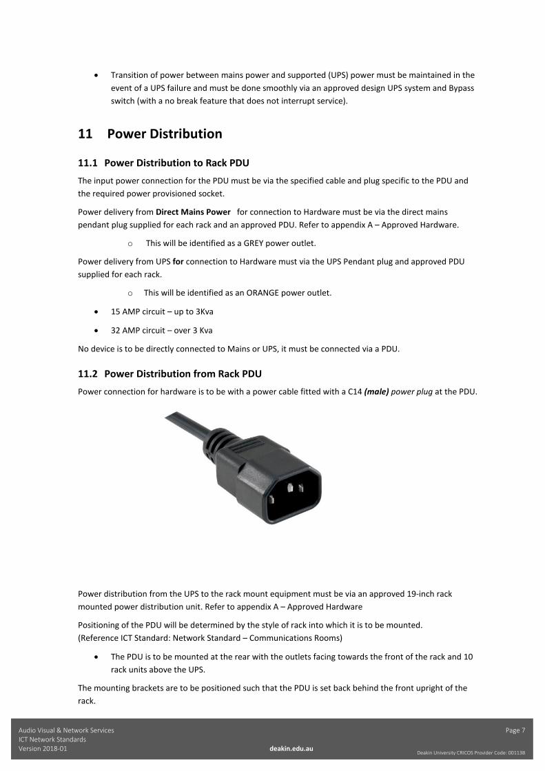
11.2 Power Distribution from Rack PDU Power connection for hardware is to be with a power cable fitted with a C14 (male) power plug at the PDU.
Power distribution from the UPS to the rack mount equipment must be via an approved 19-inch rack mounted power distribution unit. Refer to appendix A – Approved Hardware
Positioning of the PDU will be determined by the style of rack into which it is to be mounted. (Reference ICT Standard: Network Standard – Communications Rooms)
• The PDU is to be mounted at the rear with the outlets facing towards the front of the rack and 10 rack units above the UPS.
The mounting brackets are to be positioned such that the PDU is set back behind the front upright of the rack.
Audio Visual & Network Services Page 8 ICT Network Standards Version 2018-01 deakin.edu.au
Deakin University CRICOS Provider Code: 00113B
.
11.3 Mains Power Distribution to Rack Power distribution from direct mains supply to the rack mounted equipment is to be via an approved 19-inch rack mounted power distribution unit. Refer to appendix A – Approved Hardware
Positioning of the PDU will be determined by the style of rack into which it is to be mounted. (Reference ICT Standard: Network Standard – Communications Rooms)
• The PDU is to be mounted at the rear with the outlets facing towards the front of the rack and 10 rack units above the UPS.
The mounting brackets are to be positioned such that the PDU is set back behind the front upright of the rack.
The required number mains outlets and amp rating for each is to be determined by referencing UPS Selection Matrix table in section 16 of this document.
11.4 UPS Power Cable to Supply
11.4.1 Plug in UPS
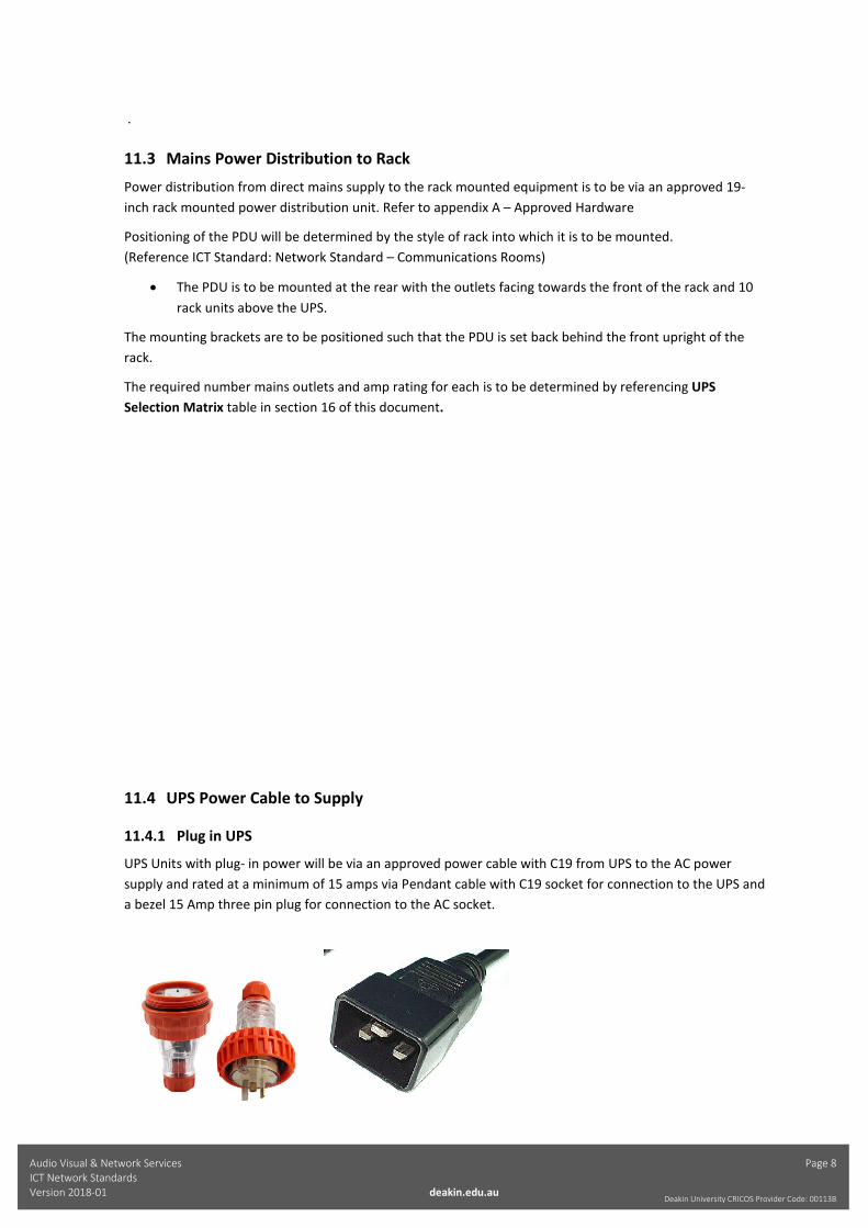
UPS Units with plug- in power will be via an approved power cable with C19 from UPS to the AC power supply and rated at a minimum of 15 amps via Pendant cable with C19 socket for connection to the UPS and a bezel 15 Amp three pin plug for connection to the AC socket.
Audio Visual & Network Services Page 9 ICT Network Standards Version 2018-01 deakin.edu.au
Deakin University CRICOS Provider Code: 00113B
Refer to appendix A – Approved Hardware.
The required installation method is to have a pendant power outlet located such that the power outlet falls into the left cable manager (as seen from rear of the rack) and is to be suspended between 1.5 and 1.6 metres above the floor level.
Any variation from the preferred installation method must be approved by the Deakin eSolutions AVN representative.
11.4.2 Hard wired
Units with hard wired connection will use suitable single or 3 phase wiring via an approved distribution board and bypass switch. Installation is to be by a registered electrician.
12 UPS Type
12.1 In-Rack UPS A UPS up to and including 3KVA (Refer to appendix A – Approved Hardware) is to be connected via 3 pin power cord to specified power outlet following the cable install standards in this document (Ref: 12.3 UPS power cable to supply)
The selected UPS shall be rack mounted in the communication rack.
• In the standard four post rack with cage nuts, slide-rails must be used as per manufacturers standards.
o Rails must be installed at the last RU (bottom of rack) and o Battery pack must be installed above UPS as required.
(Reference ICT Standard: Network Standard – Communications Rooms)
12.2 Standalone UPS Any UPS over 3 KVA is to be hard wired (adhering to manufacturers specifications) to a dedicated power circuit specified by IPG.
• All electrical work must be approved by IPG and carried out by approved and certified electrical contractors.
• Transition of power between mains power and supported (UPS) power must be maintained in the event of a UPS failure and must be done smoothly via an approved design UPS system and Bypass switch (with a no break feature that does not interrupt service).
• Refer to appendix A – Approved Hardware. The current specific models will be chosen on a case by case basis for suitability and will be in conjunction with the Deakin eSolutions AVN representative.
o The UPS must be connected via an approved distribution board ( see appendix A)

Audio Visual & Network Services Page 10 ICT Network Standards Version 2018-01 deakin.edu.au
Deakin University CRICOS Provider Code: 00113B
o The distribution board must be connected via an approved Bypass switch ( see appendix A )
12.3 Power Cable Management All pluggable power cables must be neatly and securely restrained down the vertical cable management paths at the rear of the rack when connected to Mains or to PDUs.
Securing must be done only with Velcro to align with Data cable management (cable ties are not to be used)
Power cables must not be bundled or secured with data cables and must be separated in all cases.
Wiring must not present a tripping hazard under any circumstances, in particular:
• The power outlet must not be skirting-mounted. • The power cable must not run along the floor.

Audio Visual & Network Services Page 11 ICT Network Standards Version 2018-01 deakin.edu.au
Deakin University CRICOS Provider Code: 00113B
13 UPS and PDU Management
13.1 Network Management Card and Ethernet Network Connection Each UPS is to be fitted with a Network Management Card with Environmental Monitoring to provide network connectivity.
• A UPS or PDU must be network connected to the switch stack that it supports.
• Configuration of the UPS network management card must be undertaken by the installing contractor under the direction of the eSolutions AVN representative. Campus settings will need to be obtained to complete this task.
The Cisco switch port connection for the UPS or PDU must be labelled in the switch configuration with the IP and DNS name as a description.
14 Accessibility
Any UPS or PDU must have adequate room around the device for maintenance purposes.
UPS devices must not be installed so as impede the installation or removal of internal parts or batteries.
Clear working areas must be maintained in front for rack mounted devices and both front rear access maintained for standalone UPSs.
15 Approved Hardware
PDU The approved PDU is Computer support systems (CSS) intelligent Power PDU.
There are 2 models: 16amp and 32amp.

Audio Visual & Network Services Page 12 ICT Network Standards Version 2018-01 deakin.edu.au
Deakin University CRICOS Provider Code: 00113B
16 UPS types
In-Rack UPS
Deakin eSolutions has chosen the APC- Schneider range of UPS for in-rack power protection.
Any deviation to this specified model must be authorised by the Deakin eSolutions AVN representative. The current specific models for use are:
Audio Visual & Network Services Page 13 ICT Network Standards Version 2018-01 deakin.edu.au
Deakin University CRICOS Provider Code: 00113B
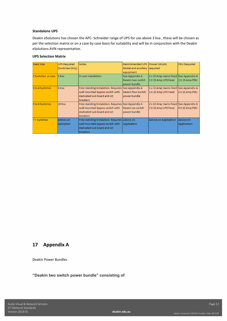
Standalone UPS
Deakin eSolutions has chosen the APC- Schneider range of UPS for use above 3 kva , these will be chosen as per the selection matrix or on a case by case basis for suitability and will be in conjunction with the Deakin eSolutions AVN representative.
UPS Selection Matrix
17 Appendix A
Deakin Power Bundles
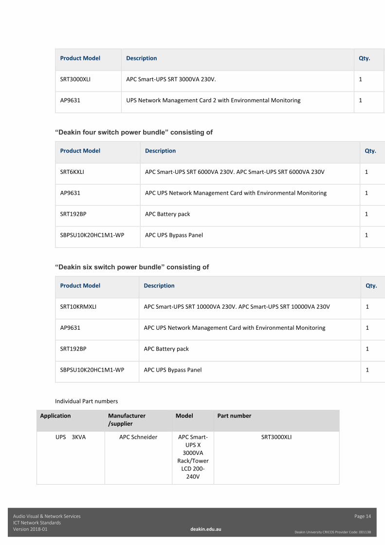
“Deakin two switch power bundle” consisting of
Audio Visual & Network Services Page 14 ICT Network Standards Version 2018-01 deakin.edu.au
Deakin University CRICOS Provider Code: 00113B
Product Model Description Qty.
SRT3000XLI APC Smart-UPS SRT 3000VA 230V. 1
AP9631 UPS Network Management Card 2 with Environmental Monitoring 1
“Deakin four switch power bundle” consisting of
Product Model Description Qty.
SRT6KXLI APC Smart-UPS SRT 6000VA 230V. APC Smart-UPS SRT 6000VA 230V 1
AP9631 APC UPS Network Management Card with Environmental Monitoring 1
SRT192BP APC Battery pack 1
SBPSU10K20HC1M1-WP APC UPS Bypass Panel 1
“Deakin six switch power bundle” consisting of
Product Model Description Qty.
SRT10KRMXLI APC Smart-UPS SRT 10000VA 230V. APC Smart-UPS SRT 10000VA 230V 1
AP9631 APC UPS Network Management Card with Environmental Monitoring 1
SRT192BP APC Battery pack 1
SBPSU10K20HC1M1-WP APC UPS Bypass Panel 1
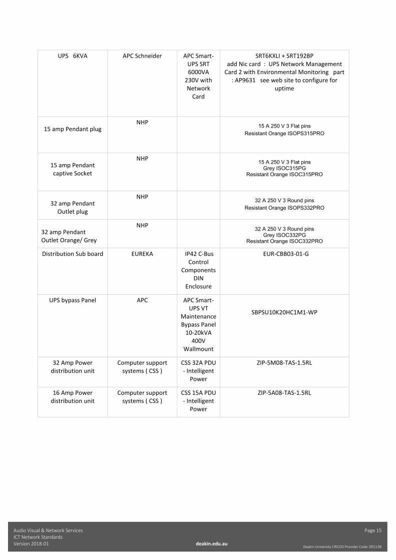
Individual Part numbers
Application Manufacturer /supplier
Model Part number
UPS 3KVA APC Schneider APC Smart-UPS X
3000VA Rack/Tower
LCD 200-240V
SRT3000XLI
Audio Visual & Network Services Page 15 ICT Network Standards Version 2018-01 deakin.edu.au
Deakin University CRICOS Provider Code: 00113B
UPS 6KVA APC Schneider APC Smart-UPS SRT 6000VA
230V with Network
Card
SRT6KXLI + SRT192BP add Nic card : UPS Network Management
Card 2 with Environmental Monitoring part : AP9631 see web site to configure for
uptime
15 amp Pendant plug
NHP 15 A 250 V 3 Flat pins
Resistant Orange ISOPS315PRO
15 amp Pendant captive Socket
NHP 15 A 250 V 3 Flat pins
Grey ISOC315PG Resistant Orange ISOC315PRO
32 amp Pendant Outlet plug
NHP 32 A 250 V 3 Round pins
Resistant Orange ISOPS332PRO
32 amp Pendant Outlet Orange/ Grey
NHP 32 A 250 V 3 Round pins
Grey ISOC332PG Resistant Orange ISOC332PRO
Distribution Sub board EUREKA IP42 C-Bus Control
Components DIN
Enclosure
EUR-CBB03-01-G
UPS bypass Panel APC APC Smart-UPS VT
Maintenance Bypass Panel
10-20kVA 400V
Wallmount
SBPSU10K20HC1M1-WP
32 Amp Power distribution unit
Computer support systems ( CSS )
CSS 32A PDU - Intelligent
Power
ZIP-5M08-TAS-1.5RL
16 Amp Power distribution unit
Computer support systems ( CSS )
CSS 15A PDU - Intelligent
Power
ZIP-5A08-TAS-1.5RL