ict project description new data center and moving ict ... data center and moving ict equipment for...
TRANSCRIPT

ICT - Project Description New Data Center and Moving ICT
Equipment for Mozambique Country Office -
Rev. 00
Partitioning and Outfitting Works for Mozambique Country Office
31st October 2016
Submitted by: Royal HaskoningDHV Maputo – Mozambique Rua de Kassuende, nº 118, 8º andar T +258 21 48 59 17/8 | F +258 21 48 59 23 E [email protected] | W www.rhdhv.co.mz

PROJECT TITLE: Partitioning and Outfitting Works for Mozambique Country Office
DOCUMENT TITLE: ICT Project Description - New Data Center and Moving IT Equipment for Mozambique Country Office
Prepared for:
AFRICAN DEVELOPMENT BANK Prepared by: Royal HaskoningDHV Rua de Kassuende, Nr. 118, 8º andar Maputo Moçambique Tel: +258 21 485917/8 Fax: +258 21 485923 Web: www.rhdhv.co.mz
Document History – Document Number - KA1301-DD-ARC-PJD-001
00 31-10-16 Issued for Review / Approval HC ST MV
Revision Date Purpose Description Prepared Checked Approved Client Appr.

ICT_Project Description Page i 31
st October 2016
ICT PROJECT DESCRIPTION
PARTITIONING AND OUTFITTING WORKS FOR MOZAMBIQUE
COUNTRY OFFICE
NEW DATA CENTER AND MOVING ICT EQUIPMENT FOR MOZAMBIQUE
COUNTRY OFFICE
Torres Rani, Avenida da Marginal, Maputo
TABLE OF CONTENTS
1. INTRODUCTION ......................................................................................................................... 1
2. PROJECT OVERVIEW .......................................................................................................... 1
2.1 Project description ..................................................................................................................... 1
3. TECHNICAL PROPOSAL............................................................................................................ 2
3.1 Solutions Description ................................................................................................................. 2
3.1.2 WAN Connectivity ................................................................................................................... 2
3.1.3 Network Active Devices .......................................................................................................... 2
3.1.4 Unified Communication (UC) equipment’s (Voice & Video) ..................................................... 2
3.2 New Data Center Installation Services....................................................................................... 3
3.2.1 Local Area Network Data & Voice Cabling Infrastructure standards ....................................... 3
3.2.2 Cabling base principles:.......................................................................................................... 8
4. MOVING SERVICES ................................................................................................................... 9
4.1 Planning .................................................................................................................................... 9
4.1.1 Before Move ........................................................................................................................... 9
4.1.2 Execution Plan ....................................................................................................................... 9
4.2 Moving and Security Services – Technical Specifications ........................................................ 10
4.3 Resources for Moving Services ............................................................................................... 10
4.3 Moving Servers and Storage – Technical Specifications ......................................................... 10
4.3.1 Resources – Moving Servers and Storage............................................................................ 11
4.4 Moving Networking Equipment – Technical Specifications ................................................... 11
4.4.1 Resources – Networking Equipment .................................................................................... 12
4.5 Moving Workstations and End Devices - Technical Specifications ........................................... 12
4.5.2 Resources – Workstations and End Devices ....................................................................... 12

ICT_Project Description Page 1 31
st October 2016
ICT PROJECT DESCRIPTION
PARTITIONING AND OUTFITTING WORKS FOR MOZAMBIQUE
COUNTRY OFFICE
NEW DATA CENTER AND MOVING ICT EQUIPMENT FOR MOZAMBIQUE
COUNTRY OFFICE
Torres Rani, Avenida da Marginal, Maputo
1. INTRODUCTION
The present description refers to justify the Design of new Data Center in the new office of African
Development Bank (AfDB) Mozambique Office in Maputo. AfDB, needs do move to the new office
premises. The new office is located at Torres Rani, Avenida da Marginal, in Maputo, half part of the
fourth floor, situated on the sea-facing section of the Building.
2. PROJECT OVERVIEW
2.1 Project description
This project aims to provide services for installation of a new data center, uninstallation, move,
reinstallation and tests of IT equipment in the new offices of AfDB in Maputo and start up the
equipment on local network.
The equipments are currently installed on JAT IV building, 3rd floor, Av. Zedequias Manganhela,
267, in Maputo, and should be moved to the new office located at Rani Towers where should be
installed.
The proposal must include the preparatory work of equipment inventory, documentation, the
components and the connections.
The implementation of the preparatory work will take place during normal working hours without
disturbing the normal functioning of the African Development Bank.
The move process is critical, so the data center, IT equipment moving will happen in the end-of-
week.
It required the service provider to submit the proposal with the documents proving the technical
certifications of manufacturers involved in this change.

ICT_Project Description Page 2 31
st October 2016
3. TECHNICAL PROPOSAL
3.1 Solutions Description
The service provider shall submit a proposal for the installation of a data center including network
cabling, RJ45 connector’s installation, network outlets and cabling termination patch panel and
among other services necessary for this purpose.
3.1.2 WAN Connectivity
The Bank has two type of WAN and Internet connectivity at the current office.
VSAT connectivity
Internet Connectivity through local Provider.
The Bank has a contract agreement with the different connectivity providers. The move or transfer
of the VSAT and Internet links will be handled separately by the BANK and the existing
connectivity providers.
3.1.3 Network Active Devices
The current network actives devices such as Routers, Switches, Firewalls, Access Points, and
servers, others IT equipment’s and Racks will be transferred from the current site to the new
location.
In addition to the existing equipment, the Bank will provide required complementary network
equipment for the new building. When the construction of the building will be on progress, in line
with the Global framework agreement with CISCO and partners to order directly from Cisco the
required network active devices.
The procurement of additional network active device will be handled directly by the BANK.
3.1.4 Unified Communication (UC) equipment’s (Voice & Video)
The existing Unified Communication equipment for Voice and Video at the current location will be
transferred to the new location.
In addition to the existing equipment, the Bank will provide required complementary UC equipment
for the new building. When the construction of the building will be on progress, in line with the
Global framework agreement with POLYCOM - MICROSOFT, and partners, The BANK will handle
directly the procurement from POLYCOM - MICROSOFT the required additional UC equipment.

ICT_Project Description Page 3 31
st October 2016
3.2 New Data Center Installation Services
3.2.1 Local Area Network Data & Voice Cabling Infrastructure standards
AfDB must guarantee that the current patch cords and trunking cables will be enough to connect
the passive devices to active devices.
The cabling and power on the rack on the new data center must be already completed before the
Move process starts.
Is not included in this project the installation of new fiber optic cabling, so the current link cables
used to connect the active devices must be reused.
The service provider must support in order to be able to convert the current PDUs with compatible
connections installed on the new data center.
The service provider must keep the room clean and organized to house the racks that will be
moved from the old office.
To streamline the cabling the Bank has adopted the followings as reference standards among
others:
1. ISO/IEC 24764 (Generic cabling for data centers)
2. ISO/IEC 11801:2002 A1 & A2 (Generic cabling for customer premises)
3. and the CENELEC EN 50173-5 (Cabling for data centers)
4. TIA 606-A (Labeling Standard for Networks)
Section Cabling system structure information
Specifications Comments
GE
NE
RA
L
Support Voice, Video and Data
Standard (response to proposal and installations will be tested against the standard)
Cat 6A, 7, 7A ( cat 7 preferred) (ISO/IEC 11801:2002 category 7/class F)
Require data sheet from the service provide.
Installation requirement
Trucking shall follow the approved color codes
Trucking facility to allow for future demands, the cabling system must be easy to expand and maintain.
Passive Components
All proposed components including the patch cords have to be produced by the same manufacturer:
The number of passive end points shall be determined by the possible number of staff to be accommodated in any given area + an increase of 30 %.

ICT_Project Description Page 4 31
st October 2016
HO
RIZ
ON
TA
L C
AB
LIN
G
Minimum
Cabling type
The horizontal 4 pair cable shall be Category
7 UTP to meet the quality and performance criteria necessary to ensure correct operation of the installation for frequencies to 500 MHz and to ensure the compliance with the warranty. The same standard shall be applied to patch cords.
The installation design and routing of all cables shall take account of the manufacturer limits as specified in the data sheet.
Category 7 cable (CAT7), ( are specified in ISO/IEC 11801:2002 category 7/class F), It is a cable standard for Ethernet and other interconnect technologies that can be made to be backwards compatible with traditional CAT5 and CAT6 Ethernet cable.
Network
Outlets (TO)
The RJ45 connector shall be screened to ensure protection against EMI and for Alien cross-talk compliance
Cabling should take into account the esthetic
and should have a minimum distance of 90cm to 1m between the cables and energy sources that can cause electromagnetic disturbances such as energy transformers, air conditioners
The horizontal cable length shall not exceed 100 m copper
300+ m for fiber
Network
Outlets
Copper Patch
Panels
(RJ45)
Each connector shall provide both T568A and T568B color code identification for the pins at the rear of the connector. The punch down is to be in accordance with the T568B color code. Reassignment of pairs shall not be accepted
The number of network outlets shall be dependent on the number of staff per given area.
To avoid installation errors, the wire organizer of the snap-in connector must be identified by the same standard color coding as the wires.
All network outlets shall be provided with labeling and identification. A transparent window shall protect the labeling tag.
Cable labeling matrix shall be part of the infrastructure acceptance test
Patch panels must have 19” equipment practice dimensions to permit mounting in standard cabinets, racks or bays
Copper Patch Panels (RJ45)
Patch Cords
All patch panels must be equipped with a cable management mechanism that provides strain relief, earthling and grounding features
The presentation of the Patch Panel must provide for sliding mechanism for proper labeling.
In the rack, the Patch Panels shall be separated by metallic patch-guides that have a closed front to protect the patch cords. The height of these guides will be 1U or 2U depending on

ICT_Project Description Page 5 31
st October 2016
the layout of the rack. The Patch Panel shall provide an automatic
contact with the metal frame of the cabinet in order to ensure grounding.
To achieve a Class EA Channel performance all Patch Cords shall be minimum of Category 7.
Uplinks
All uplinks must be color coded in RED AND BLUE to differentiate the links to the core ( backbone)
The uplink connects the core (backbone in the server Room) to the Floor Distribution switches for the Voice, data video services.
Active equipment & panels connections
In order to trace patching between the active equipment ports and the cabling termination patch panels, the ports of the active equipment should be properly documented and labeled. Fixed permanent label are required
Identification/labeling scheme should be in line with TIA-606-A
All equipment room cabinet shall be in 42U cabinet
For an orderly cord storage and easy to
management of cable installation, the following accessories may be used:
Closed 1 or 2 HU patch guides between the patch panels;
Lateral cable rings installed at both sides of the frames. The patch rings should be easily removable by rotation and have to be located on the front rails of the 19” frames in the cabinets.
The cabinets shall be able to host all standard types of active and passive equipment and provide facilities for extension to form a suite of cabinets with no modification to the structure.
All equipment room cabinet shall be 42U (600x800mm) minimum
CA
BIN
ET
AN
D R
AC
KS
INS
TA
LL
AT
ION
Cabinet arrangement
Please the arrangement of the cabinets
should ensure that: 1. Front rails of cabinets must be
recessed to provide adequate room for patch cables and Wire management accessories.
2. Adequate space for cable management
3. Arrange switches and minimize patching between cabinets & racks
4. Perforated tiles at front cabinets 5. One edge of cabinets placed at edge
of tile
WIR
EL
ES
S
Wi-Fi survey to be undertaken for the locations. Cabling should however be internal as standard
The Wireless access points should be
installed based on Wi-Fi survey and should meet 801.1n standard

ICT_Project Description Page 6 31
st October 2016
SP
AC
E I
MP
AC
T
OF
CA
BL
ING
SY
ST
EM
S
1. Allocate adequate space and careful plan location of network areas (MDA HDAs, Entrance Rooms, Telecom
2. Provide adequate space and coordinate location of cabling pathways.
3. Space in server cabinets for patch panel and cable management
EN
ER
GY
EF
FE
CIE
NC
Y –
PA
TH
WA
YS
Overhead cabling as standard
Overhead cabling requirement should be
considered in the design of the Ceiling heights to permit rails.
The overhead cabling will reduce losses due to airflow obstruction and turbulence. For old Data centers where overhead cabling was not part the requirement, all improvement work must ensure that :
all cabling under floor use smaller
diameter cable conduits or alternative network
architectures to reduce cabling volumes
• the cabling network must avoid blocking airflow to/from cabinets,
ventilated tiles, A/C, IT, and telecom equipment
EN
ER
GY
EF
FIC
IEN
CY
TE
MP
ER
AT
UR
E &
HU
MID
ITY
DC Rooms, Equipment Rooms, – Temperature: 18 – 27 °C (64 – 81 °F) – Max Relative Humidity: 60% – Max dew point: 15 °C (59 °F) – Min dew point: 5.5 °C (42 °F) to control
ESD

ICT_Project Description Page 7 31
st October 2016
EL
EC
TR
ICA
L C
AB
LIN
G S
EC
UR
ITY
The electrical cabling used to power Network and the telecommunications infrastructure should comply with industry best practices. Especially the following must be observed:
-Electrical cabling will be run separately from data cabling
-There should be a telecommunication earthing different from the building general earthing.
-All the active devices should be connected to the earthing
-All the telecommunications cabinets, closets should be connected to the earthing
-All the telecommunications devices should be powered though double conversion UPS system.
There should be lightening arrestor to protect the building and surge protection to protect the Infrastructure. Especially, there should be a surge protector on all PSTN lines.
DO
CU
ME
NT
AT
ION
The service provider should provide documentation in soft and hard copies
The physical installations of network passive and active devices must have detailed documentation that include information:
All products used
The entire system as implemented and based on the validated initial design
A diagram of each type of distribution points relative to MDA
A comprehensive overview of the installation.
A ground plane locating each sub-system installation.
The plans of the different levels of the building with the location and designation endpoint relative to HDA
The installation shall be subjected to test on completion:
The set of tests that may be conducted may include:
The connectivity test of the copper (end-to-end)
The test made fiber (end-to-end)
The type and serial number of the testing devices used must be specified.
The name of the operators ( Service provider Engineers and approving officer)
Cabling should be certified against category 6A or 7 specifications and full tests This certification will provide the length of each cable, the rate of packet loss, the resistance, impedance result made available in electronic format.

ICT_Project Description Page 8 31
st October 2016
3.2.2 Cabling base principles:
1. The trucking shall be made of 3 compartments inside.
2. Each network position workstation has two cables that extends to the equipment room. The
cables, known as the cables UTP category 7 will be used for horizontal cabling requirements.
3. Each uplink will operate at 1000 Mbps. The Uplinks will connect the different switches on
the servers Room. The uplink is multimodal optical fiber.
4. Total Positions shall be based on the design (site drawing) and number of staff regarding
offices allocation.
I. IT NETWORK CABLING
Required functions
Minimal
technical
compliance
Quantity Unit Price Total price
Country
of origin
Identification
Supply, installation and
commissioning of all the cabling,
trucking and outlets for a 1000Base
T network.
UTP Cat 7
A - Each Office will be equipped with positions configured as follows
PS PSLT LT
Each Network position is
composed of:
3 RJ-45 Outlets (2 LAN and 1 Phone)
2 Regulated Power Supply(UPS) outlets
01 normal power outlet ( not on UPS )
Number of Network positions per office according to Staff allocation
Office for 1 person 3
Office for 2 persons 5
Office for 3 persons 7
Videoconference / Meeting Room
according to the number of sets. 8 - 10
PS: refer to the design (plan & drawing) and site visit to confirm the required quantities

ICT_Project Description Page 9 31
st October 2016
4. MOVING SERVICES
4.1 Planning
The service provider shall make a schedule of all services.
The Shutdown and Start Up operation of the systems is the responsibility of the AfDB. This
process should being supervised by the project manager.
4.1.1 Before Move
The access accreditation for teams and vehicles involved in the project must be arranged in
advance.
It is responsibility of AfDB to guarantee easy access to both offices (the current and the new office)
for equipment moving process. If the destination conditions change by works or alteration of
facilities, the service provider should make a site visit to assess these changes.
The equipments must be properly switched off before the packaging process. The packages must
be packaged in corrugated board and protected with safety brackets for greater security in
transport.
4.1.2 Execution Plan
Phase 1
Record the number of links
Check and take note of cables on current data center
Record the changes to be made on move to new data center
Phase 2
Dismantling the equipment’s on the current data center
Remove the link cables to be reused on new data center
Dismantling the equipment and racks to move to new office
Phase 3
Move equipment and racks to new office
Phase 4
Installation of equipment in the new data center
Network patching, power and fiber optic
Identification and check network connections
Start up and testing the communication service providers links (WAN, VSAT, Internet and
Telecommunication providers)
Delivery the services to start up

ICT_Project Description Page 10 31
st October 2016
Phase 5
Monitoring the start-up process
Submit the final installation report
4.2 Moving and Security Services – Technical Specifications
This services consist of disassembly, packaging and move all equipment from current office of
AfDB to new offices safely.
4.3 Resources for Moving Services
1 (one) Team leader
1 (one) driver
Helpers to load and unload the equipment
Vehicle – specialized to move data center, equipped with air ride suspension, rail type lift,
sealed hardwood floor, rear closed cabin.
Insurance of goods and transport
4.3 Moving Servers and Storage – Technical Specifications
For moving services, the service provider has to make the identification of all existing connections,
record and documentation as well as updating the existing documentation.
The services include disassembly of the equipment in the current data center, move, assembly
with server consolidation, as well as support in the equipment start up on new data center.
For servers and storage devices, the service includes the identification, labelling, packaging and
moving the equipment.
Record and label the SAN cabling
Individual wrapping of all servers
The servers and storage device to move:
Model Serial Description
HP Proliant DL380 G5 Server
HP Compac dx 2300 Server
HP StorageWorks Tape Drive
KVM Monitor/Keyboard
The service provider shall make a final report which shall include all connections made.
ICT_Project Description Page 11 31
st October 2016
4.3.1 Resources – Moving Servers and Storage
The service provider must mention the number of resources allocated to this service as well the
description
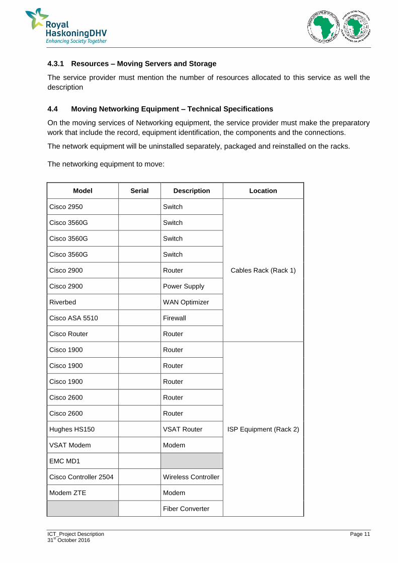
4.4 Moving Networking Equipment – Technical Specifications
On the moving services of Networking equipment, the service provider must make the preparatory
work that include the record, equipment identification, the components and the connections.
The network equipment will be uninstalled separately, packaged and reinstalled on the racks.
The networking equipment to move:
Model Serial Description Location
Cisco 2950 Switch
Cables Rack (Rack 1)
Cisco 3560G Switch
Cisco 3560G Switch
Cisco 3560G Switch
Cisco 2900 Router
Cisco 2900 Power Supply
Riverbed WAN Optimizer
Cisco ASA 5510 Firewall
Cisco Router Router
Cisco 1900 Router
ISP Equipment (Rack 2)
Cisco 1900 Router
Cisco 1900 Router
Cisco 2600 Router
Cisco 2600 Router
Hughes HS150 VSAT Router
VSAT Modem Modem
EMC MD1
Cisco Controller 2504 Wireless Controller
Modem ZTE Modem
Fiber Converter

ICT_Project Description Page 12 31
st October 2016
Fiber
Shelving Others
Perle Console
Cisco Router
Servers Rack (Rack 3) SwitchVox 305 PBX IP
SwitchVox 305 PBX IP
4.4.1 Resources – Networking Equipment
The service provider must mention the number of resources allocated to this service as well the
description.
4.5 Moving Workstations and End Devices - Technical Specifications
The service provider must provide all equipment to perform the services:
• Packaging several materials;
• Marine plywood bedsteads (floor covering);
• Doors pallets;
• Strapping the packages
4.5.2 Resources – Workstations and End Devices
To move the workstations and end devices, the service provider must make the preparatory works
that include the record, equipment identification, components and the connections.
The workstations and end devices will be uninstalled separately, packaged, moved, reinstalled and
tested on the new location.
Workstation and end devices equipment to move:
Equipment Qtd Description
Rack 2 1 36 U's
Rack 3 1 36 U's
Monitors
Docking Stations
Active Workstations 18
Shared printers 3

ICT_Project Description Page 13 31
st October 2016
Standalone printers 5
Access Points 2
TV Screen (Video Conference) 3
Webcam (Video Conference) 2
UPS 10 kVA 1
CCTV Desk 1
CCTV Monitor 1
Keyboard
Wall Monitor
Cisco Equipment 1 wall mounted
Several IT obsolete equipment
For obsolete equipment the service provider must coordinate with AfDB, where it should be stored.
The service provider must mention the number of resources allocated to this service as well the
description.
Maputo, October 2016.
Prepared by:
___________________
Herculano Cachaço, ICT