idaho supplementary guidance to the mutcd · traffic manual: idaho supplementary guidance to the...
TRANSCRIPT

Idaho Transportation Department
Traffic Manual:Idaho Supplementary Guidance to the MUTCDApril 2020

This Page Intentionally Left Blank

Traffic Manual: Idaho Supplementary Guidance to the MUTCD Page TC-1
April 2020
TRAFFIC MANUAL: IDAHO SUPPLEMENTARY GUIDANCE TO THE MUTCD
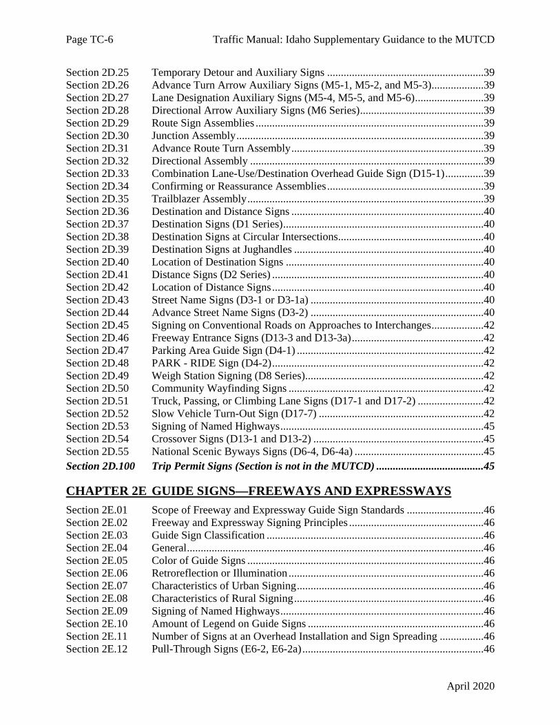
TABLE OF CONTENTS Page PART 1 GENERAL CHAPTER 1A GENERAL Section 1A.01 Purpose of Traffic Control Devices ..................................................................1 Section 1A.02 Principles of Traffic Control Devices ...............................................................1 Section 1A.03 Design of Traffic Control Devices ...................................................................1 Section 1A.04 Placement and Operation of Traffic Control Devices ......................................1 Section 1A.05 Maintenance of Traffic Control Devices ..........................................................1 Section 1A.06 Uniformity of Traffic Control Devices .............................................................1 Section 1A.07 Responsibility for Traffic Control Devices ......................................................1 Section 1A.08 Authority for Placement of Traffic Control Devices ........................................1 Section 1A.09 Engineering Study and Engineering Judgment .................................................2 Section 1A.10 Interpretations, Experimentations, Changes, and Interim Approvals ...............2 Section 1A.11 Relation to Other Publications ..........................................................................2 Section 1A.12 Color Code ........................................................................................................4 Section 1A.13 Definitions of Headings, Words, and Phrases in this Manual ..........................4 Section 1A.14 Meanings of Acronyms and Abbreviations in this Manual ..............................4 Section 1A.15 Abbreviations Used on Traffic Control Devices ..............................................4
PART 2 SIGNS CHAPTER 2A GENERAL Section 2A.01 Function and Purpose of Signs .........................................................................5 Section 2A.02 Definitions ........................................................................................................5 Section 2A.03 Standardization of Application .........................................................................5 Section 2A.04 Excessive Use of Signs .....................................................................................5 Section 2A.05 Classification of Signs ......................................................................................5 Section 2A.06 Design of Signs .................................................................................................5 Section 2A.07 Retroreflectivity and Illumination ....................................................................5 Section 2A.08 Maintaining Minimum Retroreflectivity ..........................................................5 Section 2A.09 Shapes ...............................................................................................................6 Section 2A.10 Sign Colors .......................................................................................................6 Section 2A.11 Dimensions .......................................................................................................6 Section 2A.12 Symbols ............................................................................................................6 Section 2A.13 Word Messages .................................................................................................6 Section 2A.14 Sign Borders .....................................................................................................6 Section 2A.15 Enhanced Conspicuity for Standard Signs .......................................................7 Section 2A.16 Standardization of Location ..............................................................................7

Page TC-2 Traffic Manual: Idaho Supplementary Guidance to the MUTCD
April 2020
Section 2A.17 Overhead Sign Installations ..............................................................................7 Section 2A.18 Mounting Height ...............................................................................................7 Section 2A.19 Lateral Offset ....................................................................................................7 Section 2A.20 Orientation ........................................................................................................7 Section 2A.21 Posts and Mountings .........................................................................................7 Section 2A.22 Maintenance ......................................................................................................7 Section 2A.23 Median Opening Treatments for Divided Highways with Wide Medians .......7
CHAPTER 2B REGULATORY SIGNS, BARRICADES, AND GATES Section 2B.01 Application of Regulatory Signs ....................................................................11 Section 2B.02 Design of Regulatory Signs ............................................................................11 Section 2B.03 Size of Regulatory Signs ................................................................................11 Section 2B.04 Right-of-Way at Intersections .........................................................................11 Section 2B.05 STOP Sign (R1-1) and ALL WAY Plaque (R1-3P) .......................................11 Section 2B.06 STOP Sign Applications .................................................................................11 Section 2B.07 Multi-Way Stop Applications .........................................................................11 Section 2B.08 YIELD Sign (R1-2) ........................................................................................11 Section 2B.09 YIELD Sign Applications ...............................................................................11 Section 2B.10 STOP Sign or YIELD Sign Placement ...........................................................11 Section 2B.11 Yield Here To Pedestrians Signs (R1-5 Series) ..............................................11 Section 2B.12 In-Street and Overhead Pedestrian Crossing Signs (R1-6 and R1-9) .............12 Section 2B.13 Speed Limit Sign (R2-1) .................................................................................12 Section 2B.14 Truck Speed Limit Plaque (R2-2P) ................................................................12 Section 2B.15 Night Speed Limit Plaque (R2-3P) .................................................................13 Section 2B.16 Minimum Speed Limit Plaque (R2-4P) ..........................................................13 Section 2B.17 Higher Fines Signs and Plaque (R2-6P, R2-10, and R2-11) ..........................13 Section 2B.18 Movement Prohibition Signs (R3-1 through R3-4, R3-18, and R3-27) .........13 Section 2B.19 Intersection Lane Control Signs (R3-5 through R3-8) ...................................13 Section 2B.20 Mandatory Movement Lane Control Signs (R3-5, R3-5a, R3-7, and R3-20) 13 Section 2B.21 Optional Movement Lane Control Sign (R3-6) ..............................................13 Section 2B.22 Advance Intersection Lane Control Signs (R3-8 Series) ................................14 Section 2B.23 RIGHT (LEFT) LANE MUST EXIT Sign (R3-33) .......................................14 Section 2B.24 Two-Way Left Turn Only Signs (R3-9a, R3-9b) ...........................................14 Section 2B.25 BEGIN and END Plaques (R3-9cP, R3-9dP) .................................................14 Section 2B.26 Reversible Lane Control Signs (R3-9e through R3-9i) ..................................14 Section 2B.27 Jughandle Signs (R3-23, R3-24, R3-25, and R3-26 Series) ...........................14 Section 2B.28 DO NOT PASS Sign (R4-1) ...........................................................................14 Section 2B.29 PASS WITH CARE Sign (R4-2) ....................................................................16 Section 2B.30 KEEP RIGHT EXCEPT TO PASS Sign (R4-16) and SLOWER TRAFFIC
KEEP RIGHT Sign (R4-3) .............................................................................16 Section 2B.31 TRUCKS USE RIGHT LANE Sign (R4-5) ...................................................16 Section 2B.32 Keep Right and Keep Left Signs (R4-7, R4-8) ...............................................16 Section 2B.33 STAY IN LANE Sign (R4-9) .........................................................................16 Section 2B.34 RUNAWAY VEHICLES ONLY Sign (R4-10) .............................................16 Section 2B.35 Slow Vehicle Turn-Out Signs (R4-12, R4-13, and R4-14) ............................16

Traffic Manual: Idaho Supplementary Guidance to the MUTCD Page TC-3
April 2020
Section 2B.36 DO NOT DRIVE ON SHOULDER Sign (R4-17) and DO NOT PASS ON SHOULDER Sign (R4-18) .............................................................................16
Section 2B.37 DO NOT ENTER Sign (R5-1) .......................................................................16 Section 2B.38 WRONG WAY Sign (R5-1a) .........................................................................16 Section 2B.39 Selective Exclusion Signs ...............................................................................17 Section 2B.40 ONE WAY Signs (R6-1, R6-2) ......................................................................18 Section 2B.41 Wrong-Way Traffic Control at Interchange Ramps .......................................18 Section 2B.42 Divided Highway Crossing Signs (R6-3, R6-3a) ...........................................18 Section 2B.43 Roundabout Directional Arrow Signs (R6-4, R6-4a, and R6-4b) ..................18 Section 2B.44 Roundabout Circulation Plaque (R6-5P) ........................................................18 Section 2B.45 Examples of Roundabout Signing ..................................................................18 Section 2B.46 Parking, Standing, and Stopping Signs (R7 and R8 Series) ...........................18 Section 2B.47 Design of Parking, Standing, and Stopping Signs ..........................................18 Section 2B.48 Placement of Parking, Stopping, and Standing Signs .....................................19 Section 2B.49 Emergency Restriction Signs (R8-4, R8-7, R8-8) ..........................................19 Section 2B.50 WALK ON LEFT FACING TRAFFIC and No Hitchhiking Signs (R9-1,
R9-4, R9-4a) ...................................................................................................19 Section 2B.51 Pedestrian Crossing Signs (R9-2, R9-3) .........................................................19 Section 2B.52 Traffic Signal Pedestrian and Bicycle Actuation Signs (R10-1 through
R10-4, and R10-24 through R10-26) .............................................................19 Section 2B.53 Traffic Signal Signs (R10-5 through R10-30) ................................................19 Section 2B.54 No Turn on Red Signs (R10-11 Series, R10-17a, and R10-30) .....................19 Section 2B.55 Photo Enforced Signs and Plaques (R10-18, R10-19P, R10-19aP) ...............19 Section 2B.56 Ramp Metering Signs (R10-28 and R10-29) ..................................................19 Section 2B.57 KEEP OFF MEDIAN Sign (R11-1) ...............................................................19 Section 2B.58 ROAD CLOSED Sign (R11-2) and LOCAL TRAFFIC ONLY Signs
(R11-3 Series, R11-4) .....................................................................................20 Section 2B.59 Weight Limit Signs (R12-1 through R12-5) ...................................................20 Section 2B.60 Weigh Station Signs (R13 Series) ..................................................................20 Section 2B.61 TRUCK ROUTE Sign (R14-1) ......................................................................21 Section 2B.62 Hazardous Material Signs (R14-2, R14-3) .....................................................21 Section 2B.63 National Network Signs (R14-4, R14-5) ........................................................21 Section 2B.64 Headlight Use Signs (R16-5 through R16-11) ...............................................21 Section 2B.65 FENDER BENDER Sign (R16-4) ..................................................................21 Section 2B.66 Seat Belt Symbol ............................................................................................21 Section 2B.67 Barricades .......................................................................................................21 Section 2B.68 Gates ...............................................................................................................21 Section 2B.100 CHAINS REQUIRED Sign (R16-201) (Section is not in the MUTCD) .....21
CHAPTER 2C WARNING SIGNS AND OBJECT MARKERS Section 2C.01 Function of Warning Signs .............................................................................23 Section 2C.02 Application of Warning Signs ........................................................................23 Section 2C.03 Design of Warning Signs ................................................................................23 Section 2C.04 Size of Warning Signs ....................................................................................23 Section 2C.05 Placement of Warning Signs ..........................................................................23 Section 2C.06 Horizontal Alignment Warning Signs ............................................................23

Page TC-4 Traffic Manual: Idaho Supplementary Guidance to the MUTCD
April 2020
Section 2C.07 Horizontal Alignment Signs (W1-1 through W1-5, W1-11, W1-15) .............23 Section 2C.08 Advisory Speed Plaque (W13-1P) ..................................................................23 Section 2C.09 Chevron Alignment Sign (W1-8) ...................................................................23 Section 2C.10 Combination Horizontal Alignment/Advisory Speed Signs (W1-1a, W1-
2a) ...................................................................................................................23 Section 2C.11 Combination Horizontal Alignment/Intersection Signs (W1-10 Series) ........23 Section 2C.12 One-Direction Large Arrow Sign (W1-6) ......................................................23 Section 2C.13 Truck Rollover Warning Sign (W1-13) ..........................................................24 Section 2C.14 Advisory Exit and Ramp Speed Signs (W13-2 and W13-3) ..........................24 Section 2C.15 Combination Horizontal Alignment/Advisory Exit and Ramp Speed Signs
(W13-6 and W13-7) .......................................................................................24 Section 2C.16 Hill Signs (W7-1, W7-1a) ...............................................................................24 Section 2C.17 Truck Escape Ramp Signs (W7-4 Series) ......................................................24 Section 2C.18 HILL BLOCKS VIEW Sign (W7-6) ..............................................................24 Section 2C.19 ROAD NARROWS Sign (W5-1) ...................................................................24 Section 2C.20 NARROW BRIDGE Sign (W5-2) ..................................................................24 Section 2C.21 ONE LANE BRIDGE Sign (W5-3) ...............................................................24 Section 2C.22 Divided Highway Sign (W6-1) .......................................................................28 Section 2C.23 Divided Highway Ends Sign (W6-2) ..............................................................28 Section 2C.24 Freeway or Expressway Ends Signs (W19 Series) .........................................28 Section 2C.25 Double Arrow Sign (W12-1) ..........................................................................28 Section 2C.26 DEAD END/NO OUTLET Signs (W14-1, W14-1a, W14-2, W14-2a) .........28 Section 2C.27 Low Clearance Signs (W12-2 and W12-2a) ...................................................28 Section 2C.28 BUMP and DIP Signs (W8-1, W8-2) .............................................................28 Section 2C.29 SPEED HUMP Sign (W17-1) ........................................................................28 Section 2C.30 PAVEMENT ENDS Sign (W8-3) ..................................................................28 Section 2C.31 Shoulder Signs (W8-4, W8-9, W8-17, W8-23, and W8-25) ..........................28 Section 2C.32 Surface Condition Signs (W8-5, W8-7, W8-8, W8-11, W8-13, and W8-14) 28 Section 2C.33 Warning Signs and Plaques for Motorcyclists (W8-15, W8-15P, and W8-16) 30 Section 2C.34 NO CENTER LINE Sign (W8-12) .................................................................30 Section 2C.35 Weather Condition Signs (W8-18, W8-19, W8-21, and W8-22) ...................30 Section 2C.36 Advance Traffic Control Signs (W3-1, W3-2, W3-3, W3-4) .........................30 Section 2C.37 Advance Ramp Control Signal Signs (W3-7 and W3-8) ................................31 Section 2C.38 Reduced Speed Limit Ahead Signs (W3-5, W3-5a) .......................................31 Section 2C.39 DRAW BRIDGE Sign (W3-6) .......................................................................31 Section 2C.40 Merge Signs (W4-1, W4-5) ............................................................................31 Section 2C.41 Added Lane Signs (W4-3, W4-6) ...................................................................32 Section 2C.42 Lane Ends Signs (W4-2, W9-1, W9-2) ..........................................................32 Section 2C.43 RIGHT (LEFT) LANE EXIT ONLY AHEAD Sign (W9-7) .........................32 Section 2C.44 Two-Way Traffic Sign (W6-3) .......................................................................32 Section 2C.45 NO PASSING ZONE Sign (W14-3) ..............................................................32 Section 2C.46 Intersection Warning Signs (W2-1 through W2-8) ........................................32 Section 2C.47 Two-Direction Large Arrow Sign (W1-7) ......................................................32 Section 2C.48 Traffic Signal Signs (W25-1, W25-2) ............................................................32 Section 2C.49 Vehicular Traffic Warning Signs (W8-6, W11-1, W11-5, W11-5a, W11-8,
W11-10, W11-11, W11-12P, W11-14, W11-15, and W11-15a) ...................32

Traffic Manual: Idaho Supplementary Guidance to the MUTCD Page TC-5
April 2020
Section 2C.50 Non-Vehicular Warning Signs (W11-2, W11-3, W11-4, W11-6, W11-7, W11-9, and W11-16 through W11-22) ..........................................................33
Section 2C.51 Playground Sign (W15-1) ...............................................................................33 Section 2C.52 NEW TRAFFIC PATTERN AHEAD Sign (W23-2) .....................................33 Section 2C.53 Use of Supplemental Warning Plaques ..........................................................33 Section 2C.54 Design of Supplemental Warning Plaques .....................................................34 Section 2C.55 Distance Plaques (W16-2 Series, W16-3 Series, W16-4P, W7-3aP) .............34 Section 2C.56 Supplemental Arrow Plaques (W16-5P, W16-6P) .........................................34 Section 2C.57 Hill-Related Plaques (W7-2 Series, W7-3 Series) ..........................................34 Section 2C.58 Advance Street Name Plaque (W16-8P, W16-8aP) .......................................34 Section 2C.59 CROSS TRAFFIC DOES NOT STOP Plaque (W4-4P) ................................34 Section 2C.60 SHARE THE ROAD Plaque (W16-1P) .........................................................34 Section 2C.61 Photo Enforced Plaque (W16-10P) ................................................................34 Section 2C.62 NEW Plaque (W16-15P) ................................................................................34 Section 2C.63 Object Marker Design and Placement Height ................................................34 Section 2C.64 Object Markers for Obstructions Within the Roadway ..................................35 Section 2C.65 Object Markers for Obstructions Adjacent to the Roadway ...........................35 Section 2C.66 Object Markers for Ends of Roadways ...........................................................35 Section 2C.100 Radar Speed Feedback Changeable Message Signs (Section is not in the
MUTCD) ........................................................................................................35
CHAPTER 2D GUIDE SIGNS—CONVENTIONAL ROADS Section 2D.01 Scope of Conventional Road Guide Sign Standards ......................................37 Section 2D.02 Application .....................................................................................................37 Section 2D.03 Color, Retroreflection, and Illumination ........................................................37 Section 2D.04 Size of Signs ...................................................................................................37 Section 2D.05 Lettering Style ................................................................................................37 Section 2D.06 Size of Lettering .............................................................................................37 Section 2D.07 Amount of Legend ..........................................................................................37 Section 2D.08 Arrows ............................................................................................................37 Section 2D.09 Numbered Highway Systems .........................................................................37 Section 2D.10 Route Signs and Auxiliary Signs ....................................................................37 Section 2D.11 Design of Route Signs ....................................................................................37 Section 2D.12 Design of Route Sign Auxiliaries ...................................................................38 Section 2D.13 Junction Auxiliary Sign (M2-1) ......................................................................38 Section 2D.14 Combination Junction Sign (M2-2) ................................................................38 Section 2D.15 Cardinal Direction Auxiliary Signs (M3-1 through M3-4) ............................38 Section 2D.16 Auxiliary Signs for Alternative Routes (M4 Series) ......................................38 Section 2D.17 ALTERNATE Auxiliary Signs (M4-1, M4-1a) .............................................38 Section 2D.18 BY-PASS Auxiliary Sign (M4-2) ...................................................................38 Section 2D.19 BUSINESS Auxiliary Sign (M4-3) ................................................................38 Section 2D.20 TRUCK Auxiliary Sign (M4-4) ......................................................................38 Section 2D.21 TO Auxiliary Sign (M4-5) ..............................................................................38 Section 2D.22 END Auxiliary Sign (M4-6) ...........................................................................39 Section 2D.23 BEGIN Auxiliary Sign (M4-14) .....................................................................39 Section 2D.24 TEMPORARY Auxiliary Signs (M4-7, M4-7a) ............................................39
Page TC-6 Traffic Manual: Idaho Supplementary Guidance to the MUTCD
April 2020
Section 2D.25 Temporary Detour and Auxiliary Signs .........................................................39 Section 2D.26 Advance Turn Arrow Auxiliary Signs (M5-1, M5-2, and M5-3) ...................39 Section 2D.27 Lane Designation Auxiliary Signs (M5-4, M5-5, and M5-6) .........................39 Section 2D.28 Directional Arrow Auxiliary Signs (M6 Series) .............................................39 Section 2D.29 Route Sign Assemblies ...................................................................................39 Section 2D.30 Junction Assembly ..........................................................................................39 Section 2D.31 Advance Route Turn Assembly ......................................................................39 Section 2D.32 Directional Assembly .....................................................................................39 Section 2D.33 Combination Lane-Use/Destination Overhead Guide Sign (D15-1) ..............39 Section 2D.34 Confirming or Reassurance Assemblies .........................................................39 Section 2D.35 Trailblazer Assembly ......................................................................................39 Section 2D.36 Destination and Distance Signs ......................................................................40 Section 2D.37 Destination Signs (D1 Series) .........................................................................40 Section 2D.38 Destination Signs at Circular Intersections .....................................................40 Section 2D.39 Destination Signs at Jughandles .....................................................................40 Section 2D.40 Location of Destination Signs ........................................................................40 Section 2D.41 Distance Signs (D2 Series) .............................................................................40 Section 2D.42 Location of Distance Signs .............................................................................40 Section 2D.43 Street Name Signs (D3-1 or D3-1a) ...............................................................40 Section 2D.44 Advance Street Name Signs (D3-2) ...............................................................40 Section 2D.45 Signing on Conventional Roads on Approaches to Interchanges ...................42 Section 2D.46 Freeway Entrance Signs (D13-3 and D13-3a) ................................................42 Section 2D.47 Parking Area Guide Sign (D4-1) ....................................................................42 Section 2D.48 PARK - RIDE Sign (D4-2) .............................................................................42 Section 2D.49 Weigh Station Signing (D8 Series) .................................................................42 Section 2D.50 Community Wayfinding Signs .......................................................................42 Section 2D.51 Truck, Passing, or Climbing Lane Signs (D17-1 and D17-2) ........................42 Section 2D.52 Slow Vehicle Turn-Out Sign (D17-7) ............................................................42 Section 2D.53 Signing of Named Highways ..........................................................................45 Section 2D.54 Crossover Signs (D13-1 and D13-2) ..............................................................45 Section 2D.55 National Scenic Byways Signs (D6-4, D6-4a) ...............................................45 Section 2D.100 Trip Permit Signs (Section is not in the MUTCD) .......................................45
CHAPTER 2E GUIDE SIGNS—FREEWAYS AND EXPRESSWAYS Section 2E.01 Scope of Freeway and Expressway Guide Sign Standards ............................46 Section 2E.02 Freeway and Expressway Signing Principles .................................................46 Section 2E.03 Guide Sign Classification ...............................................................................46 Section 2E.04 General ............................................................................................................46 Section 2E.05 Color of Guide Signs ......................................................................................46 Section 2E.06 Retroreflection or Illumination .......................................................................46 Section 2E.07 Characteristics of Urban Signing ....................................................................46 Section 2E.08 Characteristics of Rural Signing .....................................................................46 Section 2E.09 Signing of Named Highways ..........................................................................46 Section 2E.10 Amount of Legend on Guide Signs ................................................................46 Section 2E.11 Number of Signs at an Overhead Installation and Sign Spreading ................46 Section 2E.12 Pull-Through Signs (E6-2, E6-2a) ..................................................................46

Traffic Manual: Idaho Supplementary Guidance to the MUTCD Page TC-7
April 2020
Section 2E.13 Designation of Destinations ............................................................................46 Section 2E.14 Size and Style of Letters and Signs ................................................................47 Section 2E.15 lnterline and Edge Spacing .............................................................................47 Section 2E.16 Sign Borders ...................................................................................................47 Section 2E.17 Abbreviations ..................................................................................................47 Section 2E.18 Symbols ..........................................................................................................47 Section 2E.19 Arrows for Interchange Guide Signs ..............................................................47 Section 2E.20 Signing for Option Lanes at Splits and Multi-Lane Exits ..............................48 Section 2E.21 Design of Overhead Arrow-per-Lane Guide Signs for Option Lanes ............48 Section 2E.22 Design of Freeway and Expressway Diagrammatic Guide Signs for Option
Lanes ..............................................................................................................48 Section 2E.23 Signing for Intermediate and Minor Interchange Multi-Lane Exits with an
Option Lane ....................................................................................................48 Section 2E.24 Signing for Interchange Lane Drops ...............................................................48 Section 2E.25 Overhead Sign Installations ............................................................................48 Section 2E.26 Lateral Offset ..................................................................................................48 Section 2E.27 Route Signs and Trailblazer Assemblies ........................................................48 Section 2E.28 Eisenhower Interstate System Signs (M1-10, M1-10a) ..................................48 Section 2E.29 Signs for Intersections at Grade ......................................................................50 Section 2E.30 Interchange Guide Signs .................................................................................50 Section 2E.31 Interchange Exit Numbering ...........................................................................50 Section 2E.32 Interchange Classification ..............................................................................50 Section 2E.33 Advance Guide Signs .....................................................................................50 Section 2E.34 Next Exit Plaques ...........................................................................................50 Section 2E.35 Other Supplemental Guide Signs ....................................................................50 Section 2E.36 Exit Direction Signs ........................................................................................50 Section 2E.37 Exit Gore Signs (E5-1 Series) .........................................................................50 Section 2E.38 Post-Interchange Signs ...................................................................................50 Section 2E.39 Post-Interchange Distance Signs ....................................................................50 Section 2E.40 Interchange Sequence Signs ...........................................................................50 Section 2E.41 Community Interchanges Identification Signs ...............................................51 Section 2E.42 NEXT XX EXITS Sign ..................................................................................51 Section 2E.43 Signing by Type of Interchange .....................................................................51 Section 2E.44 Freeway-to-Freeway Interchange ...................................................................51 Section 2E.45 Cloverleaf Interchange ....................................................................................51 Section 2E.46 Cloverleaf Interchange with Collector-Distributor Roadways .......................51 Section 2E.47 Partial Cloverleaf Interchange ........................................................................51 Section 2E.48 Diamond Interchange ......................................................................................51 Section 2E.49 Diamond Interchange in Urban Area ..............................................................51 Section 2E.50 Closely-Spaced Interchanges ..........................................................................51 Section 2E.51 Minor Interchange ..........................................................................................51 Section 2E.52 Signing on Conventional Road Approaches and Connecting Roadways .......51 Section 2E.53 Wrong-Way Traffic Control at Interchange Ramps .......................................51 Section 2E.54 Weigh Station Signing ....................................................................................51

Page TC-8 Traffic Manual: Idaho Supplementary Guidance to the MUTCD
April 2020
CHAPTER 2F TOLL ROAD SIGNS Section 2F.01 Scope ...............................................................................................................52 Section 2F.02 Sizes of Toll Road Signs .................................................................................52 Section 2F.03 Use of Purple Backgrounds and Underlay Panels with ETC Account
Pictographs .....................................................................................................52 Section 2F.04 Size of ETC Pictographs .................................................................................52 Section 2F.05 Regulatory Signs for Toll Plazas ....................................................................52 Section 2F.06 Pay Toll Advance Warning Sign (W9-6) .......................................................52 Section 2F.07 Pay Toll Advance Warning Plaque (W9-6P) ..................................................52 Section 2F.08 Stop Ahead Pay Toll Warning Sign (W9-6a) .................................................52 Section 2F.09 Stop Ahead Pay Toll Warning Plaque (W9-6aP) ...........................................52 Section 2F.10 LAST EXIT BEFORE TOLL Warning Plaque (W16-16P) ...........................52 Section 2F.11 TOLL Auxiliary Sign (M4-15) .......................................................................52 Section 2F.13 Toll Facility and Toll Plaza Guide Signs – General .......................................52 Section 2F.14 Advance Signs for Conventional Toll Plazas .................................................53 Section 2F.15 Advance Signs for Toll Plazas on Diverging Alignments from Open-Road
ETC Account-Only Lanes ..............................................................................53 Section 2F.16 Toll Plaza Canopy Signs .................................................................................53 Section 2F.17 Guide Signs for Entrances to ETC Account-Only Facilities ..........................53 Section 2F.18 ETC Program Information Signs ....................................................................53
CHAPTER 2G PREFERENTIAL AND MANAGED LANE SIGNS Section 2G.01 Scope ...............................................................................................................53 Section 2G.02 Sizes of Preferential and Managed Lane Signs ..............................................53 Section 2G.03 Regulatory Signs for Preferential Lanes – General ........................................53 Section 2G.04 Preferential Lane Vehicle Occupancy Definition Regulatory Signs (R3-10
Series and R3-13 Series) ................................................................................53 Section 2G.05 Preferential Lane Periods of Operation Regulatory Signs (R3-11 Series and
R3-14 Series) ..................................................................................................53 Section 2G.06 Preferential Lane Advance Regulatory Signs (R3-12, R3-12e, R3-12f,
R3-15, R3-15a, and R3-15d) ..........................................................................53 Section 2G.07 Preferential Lane Ends Regulatory Signs (R3-12a, R3-12b, R3-12c,
R3-12d, R3-12g, R3-12h, R3-15b, R3-15c, and R3-15e) ..............................53 Section 2G.08 Warning Signs on Median Barriers for Preferential Lanes ............................54 Section 2G.09 High-Occupancy Vehicle (HOV) Plaque (W16-11P) ....................................54 Section 2G.10 Preferential Lane Guide Signs – General .......................................................54 Section 2G.11 Guide Signs for Initial Entry Points to Preferential Lanes .............................54 Section 2G.12 Guide Signs for Intermediate Entry Points to Preferential Lanes ...................54 Section 2G.13 Guide Signs for Egress from Preferential Lanes to General-Purpose Lanes ..54 Section 2G.14 Guide Signs for Direct Entrances to Preferential Lanes from Another
Highway .........................................................................................................54 Section 2G.15 Guide Signs for Direct Exits from Preferential Lanes to Another Highway ..54 Section 2G.16 Signs for Priced Managed Lanes – General ...................................................54 Section 2G.17 Regulatory Signs for Priced Managed Lanes .................................................54 Section 2G.18 Guide Signs for Priced Managed Lanes .........................................................54

Traffic Manual: Idaho Supplementary Guidance to the MUTCD Page TC-9
April 2020
CHAPTER 2H GENERAL INFORMATION SIGNS Section 2H.01 Sizes of General Information Signs ................................................................55 Section 2H.02 General Information Signs (I Series) ..............................................................55 Section 2H.03 Traffic Signal Speed Sign (I1-1) .....................................................................55 Section 2H.04 Miscellaneous Information Signs ...................................................................55 Section 2H.05 Reference Location Signs (D10-1 through D10-3) and Intermediate
Reference Location Signs (D10-1a through D10-3a) .....................................58 Section 2H.06 Enhanced Reference Location Signs (D10-4, D10-5) ....................................58 Section 2H.07 Auto Tour Route Signs ...................................................................................58 Section 2H.08 Acknowledgment Signs ..................................................................................62
CHAPTER 2I GENERAL SERVICE SIGNS Section 2I.01 Sizes of General Service Signs .......................................................................63 Section 2I.02 General Service Signs for Conventional Roads ..............................................63 Section 2I.03 General Service Signs for Freeways and Expressways ..................................63 Section 2I.04 Interstate Oasis Signing ..................................................................................63 Section 2I.05 Rest Area and Other Roadside Area Signs .....................................................63 Section 2I.06 Brake Check Area Signs (D5-13 and D5-14) .................................................63 Section 2I.07 Chain-Up Area Signs (D5-15 and D5-16) ......................................................63 Section 2I.08 Tourist Information and Welcome Center Signs ............................................63 Section 2I.09 Radio Information Signing .............................................................................64 Section 2I.10 TRAVEL INFO CALL 511 Signs (D12-5 and D12-5a) ................................64 Section 2I.11 Carpool and Ridesharing Signing ...................................................................64
CHAPTER 2J SPECIFIC SERVICE SIGNS Section 2J.01 Eligibility ........................................................................................................65 Section 2J.02 Application .....................................................................................................65 Section 2J.03 Logos and Logo Sign Panels ..........................................................................65 Section 2J.04 Number and Size of Signs and Logo Sign Panels ..........................................65 Section 2J.05 Size of Lettering .............................................................................................65 Section 2J.06 Signs at Interchanges ......................................................................................65 Section 2J.07 Single-Exit Interchanges .................................................................................65 Section 2J.08 Double-Exit Interchanges ...............................................................................65 Section 2J.09 Specific Service Trailblazer Signs ..................................................................65 Section 2J.10 Signs at Intersections ......................................................................................65 Section 2J.11 Signing Policy .................................................................................................65
CHAPTER 2K TOURIST-ORIENTED DIRECTIONAL SIGNS Section 2K.01 Purpose and Application .................................................................................66 Section 2K.02 Design .............................................................................................................66 Section 2K.03 Style and Size of Lettering .............................................................................66 Section 2K.04 Arrangement and Size of Signs ......................................................................66 Section 2K.05 Advance Signs ................................................................................................66 Section 2K.06 Sign Locations ................................................................................................66 Section 2K.07 State Policy .....................................................................................................66
Page TC-10 Traffic Manual: Idaho Supplementary Guidance to the MUTCD
April 2020
CHAPTER 2L CHANGEABLE MESSAGE SIGNS Section 2L.01 Description of Changeable Message Signs .....................................................66 Section 2L.02 Applications of Changeable Message Signs ...................................................66 Section 2L.03 Legibility and Visibility of Changeable Message Signs .................................66 Section 2L.04 Design Characteristics of Changeable Message Signs ...................................66 Section 2L.05 Message Length and Units of Information .....................................................66 Section 2L.06 Installation of Permanent Changeable Message Signs ...................................66
CHAPTER 2M RECREATIONAL AND CULTURAL INTEREST AREA SIGNS
Section 2M.01 Scope ...............................................................................................................67 Section 2M.02 Application of Recreational and Cultural Interest Area Signs .......................67 Section 2M.03 Regulatory and Warning Signs .......................................................................67 Section 2M.04 General Design Requirements for Recreational and Cultural Interest Area
Symbol Guide Signs .......................................................................................68 Section 2M.05 Symbol Sign Sizes ..........................................................................................68 Section 2M.06 Use of Educational Plaques ............................................................................68 Section 2M.07 Use of Prohibitive Circle and Diagonal Slash for Non-Road Applications ...68 Section 2M.08 Placement of Recreational and Cultural Interest Area Symbol Signs ............68 Section 2M.09 Destination Guide Signs .................................................................................69 Section 2M.10 Memorial or Dedication Signing ....................................................................70 Section 2M.100 Historic and Geologic Site Signs (Section is not in the MUTCD) ...............70
CHAPTER 2N EMERGENCY MANAGEMENT SIGNING Section 2N.01 Emergency Management ................................................................................72 Section 2N.02 Design of Emergency Management Signs ......................................................72 Section 2N.03 Evacuation Route Signs (EM-1 and EM-1a) ..................................................72 Section 2N.04 AREA CLOSED Sign (EM-2) ........................................................................72 Section 2N.05 TRAFFIC CONTROL POINT Sign (EM-3) ..................................................72 Section 2N.06 MAINTAIN TOP SAFE SPEED Sign (EM-4) ..............................................72 Section 2N.07 ROAD (AREA) USE PERMIT REQUIRED FOR THRU TRAFFIC Sign
(EM-5) ............................................................................................................72 Section 2N.08 Emergency Aid Center Signs (EM-6 Series) ..................................................72 Section 2N.09 Shelter Directional Signs (EM-7 Series) ........................................................72
PART 3 MARKINGS
CHAPTER 3A GENERAL Section 3A.01 Functions and Limitations ..............................................................................73 Section 3A.02 Standardization of Application .......................................................................73 Section 3A.03 Maintaining Minimum Pavement Marking Retroreflectivity .........................73 Section 3A.04 Materials .........................................................................................................73 Section 3A.05 Colors ..............................................................................................................73 Section 3A.06 Functions, Widths, and Patterns of Longitudinal Pavement Markings ..........73

Traffic Manual: Idaho Supplementary Guidance to the MUTCD Page TC-11
April 2020
CHAPTER 3B PAVEMENT AND CURB MARKINGS Section 3B.01 Yellow Center Line Pavement Markings and Warrants .................................73 Section 3B.02 No-Passing Zone Pavement Markings and Warrants .....................................74 Section 3B.03 Other Yellow Longitudinal Pavement Markings ............................................74 Section 3B.04 White Lane Line Pavement Markings and Warrants ......................................74 Section 3B.05 Other White Longitudinal Pavement Markings ..............................................79 Section 3B.06 Edge Line Pavement Markings .......................................................................79 Section 3B.07 Warrants for Use of Edge Lines .....................................................................79 Section 3B.08 Extensions Through Intersections or Interchanges .........................................79 Section 3B.09 Lane-Reduction Transition Markings .............................................................79 Section 3B.10 Approach Markings for Obstructions .............................................................79 Section 3B.11 Raised Pavement Markers – General ..............................................................79 Section 3B.12 Raised Pavement Markers as Vehicle Positioning Guides with Other
Longitudinal Markings ...................................................................................79 Section 3B.13 Raised Pavement Markers Supplementing Other Markings ...........................79 Section 3B.14 Raised Pavement Markers Substituting for Pavement Markings ...................79 Section 3B.15 Transverse Markings ......................................................................................79 Section 3B.16 Stop and Yield Lines ......................................................................................79 Section 3B.17 Do Not Block Intersection Markings ..............................................................80 Section 3B.18 Crosswalk Markings .......................................................................................80 Section 3B.19 Parking Space Markings .................................................................................81 Section 3B.20 Pavement Word, Symbol, and Arrow Markings ............................................81 Section 3B.21 Speed Measurement Markings .......................................................................84 Section 3B.22 Speed Reduction Markings .............................................................................84 Section 3B.23 Curb Markings ................................................................................................84 Section 3B.24 Chevron and Diagonal Crosshatch Markings .................................................84 Section 3B.25 Speed Hump Markings ...................................................................................84 Section 3B.26 Advance Speed Hump Markings ....................................................................84
CHAPTER 3C ROUNDABOUT MARKINGS Section 3C.01 General ............................................................................................................85 Section 3C.02 White Lane Line Pavement Markings for Roundabouts ................................85 Section 3C.03 Edge Line Pavement Markings for Roundabout Circulatory Roadways ........85 Section 3C.04 Yield Lines for Roundabouts ..........................................................................85 Section 3C.05 Crosswalk Markings at Roundabouts .............................................................85 Section 3C.06 Word, Symbol, and Arrow Pavement Markings for Roundabouts .................85 Section 3C.07 Markings for Other Circular Intersections ......................................................85
CHAPTER 3D MARKINGS FOR PREFERENTIAL LANES Section 3D.01 Preferential Lane Word and Symbol Markings ..............................................85 Section 3D.02 Preferential Lane Longitudinal Markings for Motor Vehicles .......................85
CHAPTER 3E MARKINGS FOR TOLL PLAZAS Section 3E.01 Markings for Toll Plazas ................................................................................85

Page TC-12 Traffic Manual: Idaho Supplementary Guidance to the MUTCD
April 2020
CHAPTER 3F DELINEATORS Section 3F.01 Delineators ......................................................................................................86 Section 3F.02 Delineator Design ...........................................................................................86 Section 3F.03 Delineator Application ....................................................................................86 Section 3F.04 Delineator Placement and Spacing .................................................................86
CHAPTER 3G COLORED PAVEMENTS Section 3G.01 General ............................................................................................................88
CHAPTER 3H CHANNELIZING DEVICES USED FOR EMPHASIS OF PAVEMENT MARKING PATTERNS
Section 3H.01 Channelizing Devices .....................................................................................88
CHAPTER 3I ISLANDS Section 3I.01 General ............................................................................................................88 Section 3I.02 Approach-End Treatment ...............................................................................88 Section 3I.03 Island Marking Application ............................................................................88 Section 3I.04 Island Marking Colors ....................................................................................88 Section 3I.05 Island Delineation ...........................................................................................88 Section 3I.06 Pedestrian Islands and Medians ......................................................................88
CHAPTER 3J RUMBLE STRIP MARKINGS Section 3J.01 Longitudinal Rumble Strip Markings .............................................................88 Section 3J.02 Transverse Rumble Strip Markings ................................................................88
CHAPTER 3K HIGHWAY MEMORIAL MARKERS AND OTHER MARKERS (Chapter is not in the MUTCD)
Section 3K.01 Traffic Accident Memorials (Section is not in the MUTCD) .......................89 Section 3K.02 Blue Star Memorial Markers (Section is not in the MUTCD) .....................89 Section 3K.03 Private Approach Markers (Section is not in the MUTCD) .........................89
PART 4 HIGHWAY TRAFFIC SIGNALS
CHAPTER 4A GENERAL Section 4A.01 Types ...............................................................................................................91 Section 4A.02 Definitions Relating to Highway Traffic Signals ...........................................91
CHAPTER 4B TRAFFIC CONTROL SIGNALS—GENERAL Section 4B.01 General ............................................................................................................91 Section 4B.02 Basis of Installation or Removal of Traffic Control Signals ..........................91 Section 4B.03 Advantages and Disadvantages of Traffic Control Signals ............................91 Section 4B.04 Alternatives to Traffic Control Signals ...........................................................91 Section 4B.05 Adequate Roadway Capacity ..........................................................................91

Traffic Manual: Idaho Supplementary Guidance to the MUTCD Page TC-13
April 2020
CHAPTER 4C TRAFFIC CONTROL SIGNAL NEEDS STUDIES Section 4C.01 Studies and Factors for Justifying Traffic Control Signals ............................92 Section 4C.02 Warrant 1, Eight-Hour Vehicular Volume .....................................................92 Section 4C.03 Warrant 2, Four-Hour Vehicular Volume ......................................................92 Section 4C.04 Warrant 3, Peak Hour .....................................................................................92 Section 4C.05 Warrant 4, Pedestrian Volume ........................................................................92 Section 4C.06 Warrant 5, School Crossing ............................................................................92 Section 4C.07 Warrant 6, Coordinated Signal System ..........................................................92 Section 4C.08 Warrant 7, Crash Experience ..........................................................................92 Section 4C.09 Warrant 8, Roadway Network ........................................................................92 Section 4C.10 Warrant 9, Intersection Near a Grade Crossing ..............................................92
CHAPTER 4D TRAFFIC CONTROL SIGNAL FEATURES Section 4D.01 General ............................................................................................................93 Section 4D.02 Responsibility for Operation and Maintenance ..............................................93 Section 4D.03 Provisions for Pedestrians ...............................................................................93 Section 4D.04 Meaning of Vehicular Signal Indications .......................................................93 Section 4D.05 Application of Steady Signal Indications .......................................................93 Section 4D.06 Signal Indications – Design, Illumination, Color, and Shape .........................94 Section 4D.07 Size of Vehicular Signal Indications ..............................................................94 Section 4D.08 Positions of Signal Indications Within a Signal Face – General ....................94 Section 4D.09 Positions of Signal Indications Within a Vertical Signal Face .......................94 Section 4D.10 Positions of Signal Indications Within a Horizontal Signal Face ...................94 Section 4D.11 Number of Signal Faces on an Approach .......................................................94 Section 4D.12 Visibility, Aiming, and Shielding of Signal Faces .........................................94 Section 4D.13 Lateral Positioning of Signal Faces ................................................................94 Section 4D.14 Longitudinal Positioning of Signal Faces .......................................................94 Section 4D.15 Mounting Height of Signal Faces ...................................................................94 Section 4D.16 Lateral Offset (Clearance) of Signal Faces .....................................................94 Section 4D.17 Signal Indications for Left-Turn Movements – General ................................95 Section 4D.18 Signal Indications for Permissive Only Mode Left-Turn Movements ...........95 Section 4D.19 Signal Indications for Protected Only Mode Left-Turn Movements ..............95 Section 4D.20 Signal Indications for Protected/Permissive Mode Left-Turn Movements ....95 Section 4D.21 Signal Indications for Right-Turn Movements – General ..............................95 Section 4D.22 Signal Indications for Permissive Only Mode Right-Turn Movements .........95 Section 4D.23 Signal Indications for Protected Only Mode Right-Turn Movements ...........95 Section 4D.24 Signal Indications for Protected/Permissive Mode Right-Turn Movements ..95 Section 4D.25 Signal Indications for Approaches With Shared Left-Turn/Right-Turn Lanes
and No Through Movement ...........................................................................95 Section 4D.26 Yellow Change and Red Clearance Intervals .................................................95 Section 4D.27 Preemption and Priority Control of Traffic Control Signals ..........................98 Section 4D.28 Flashing Operation of Traffic Control Signals – General ..............................98 Section 4D.29 Flashing Operation – Transition Into Flashing Mode .....................................98 Section 4D.30 Flashing Operation – Signal Indications During Flashing Mode ...................98 Section 4D.31 Flashing Operation – Transition Out of Flashing Mode .................................98

Page TC-14 Traffic Manual: Idaho Supplementary Guidance to the MUTCD
April 2020
Section 4D.32 Temporary and Portable Traffic Control Signals ...........................................98 Section 4D.33 Lateral Offset of Signal Supports and Cabinets .............................................98 Section 4D.34 Use of Signs at Signalized Locations .............................................................98 Section 4D.35 Use of Pavement Markings at Signalized Locations ......................................98
CHAPTER 4E PEDESTRIAN CONTROL FEATURES Section 4E.01 Pedestrian Signal Heads .................................................................................99 Section 4E.02 Meaning of Pedestrian Signal Head Indications .............................................99 Section 4E.03 Application of Pedestrian Signal Heads .........................................................99 Section 4E.04 Size, Design, and Illumination of Pedestrian Signal Head Indications ..........99 Section 4E.05 Location and Height of Pedestrian Signal Heads ...........................................99 Section 4E.06 Pedestrian Intervals and Signal Phases ...........................................................99 Section 4E.07 Countdown Pedestrian Signals .......................................................................99 Section 4E.08 Pedestrian Detectors .......................................................................................99 Section 4E.09 Accessible Pedestrian Signals and Detectors – General .................................99 Section 4E.10 Accessible Pedestrian Signals and Detectors – Location ...............................99 Section 4E.11 Accessible Pedestrian Signals and Detectors – Walk Indications ..................99 Section 4E.12 Accessible Pedestrian Signals and Detectors – Tactile Arrows and Locator
Tones ............................................................................................................100 Section 4E.13 Accessible Pedestrian Signals and Detectors – Extended Pushbutton Press
Features ........................................................................................................100
CHAPTER 4F PEDESTRIAN HYBRID BEACONS Section 4F.01 Application of Pedestrian Hybrid Beacons ...................................................100 Section 4F.02 Design of Pedestrian Hybrid Beacons ..........................................................100 Section 4F.03 Operation of Pedestrian Hybrid Beacons .....................................................100
CHAPTER 4G TRAFFIC CONTROL SIGNALS AND HYBRID BEACONS FOR EMERGENCY-VEHICLE ACCESS
Section 4G.01 Application of Emergency-Vehicle Traffic Control Signals and Hybrid Beacons ........................................................................................................100
Section 4G.02 Design of Emergency-Vehicle Traffic Control Signals ................................100 Section 4G.03 Operation of Emergency-Vehicle Traffic Control Signals ...........................100 Section 4G.04 Emergency-Vehicle Hybrid Beacons ...........................................................100
CHAPTER 4H TRAFFIC CONTROL SIGNALS FOR ONE-LANE, TWO-WAY FACILITIES
Section 4H.01 Application of Traffic Control Signals for One-Lane, Two-Way Facilities 100 Section 4H.02 Design of Traffic Control Signals for One-Lane, Two-Way Facilities ........101 Section 4H.03 Operation of Traffic Control Signals for One-Lane, Two-Way Facilities ...101
CHAPTER 4I TRAFFIC CONTROL SIGNALS FOR FREEWAY ENTRANCE RAMPS
Section 4I.01 Application of Freeway Entrance Ramp Control Signals .............................101

Traffic Manual: Idaho Supplementary Guidance to the MUTCD Page TC-15
April 2020
Section 4I.02 Design of Freeway Entrance Ramp Control Signals ....................................101 Section 4I.03 Operation of Freeway Entrance Ramp Control Signals ...............................101
CHAPTER 4J TRAFFIC CONTROL FOR MOVABLE BRIDGES Section 4J.01 Application of Traffic Control for Movable Bridges ...................................101 Section 4J.02 Design and Location of Movable Bridge Signals and Gates ........................101 Section 4J.03 Operation of Movable Bridge Signals and Gates .........................................101
CHAPTER 4K HIGHWAY TRAFFIC SIGNALS AT TOLL PLAZAS Section 4K.01 Traffic Signals at Toll Plazas ........................................................................101 Section 4K.02 Lane-Use Control Signals at or Near Toll Plazas .........................................101 Section 4K.03 Warning Beacons at Toll Plazas ...................................................................101
CHAPTER 4L FLASHING BEACONS Section 4L.01 General Design and Operation of Flashing Beacons ....................................102 Section 4L.02 Intersection Control Beacon .........................................................................102 Section 4L.03 Warning Beacon ...........................................................................................102 Section 4L.04 Speed Limit Sign Beacon .............................................................................105 Section 4L.05 Stop Beacon ..................................................................................................106
CHAPTER 4M LANE-USE CONTROL SIGNALS Section 4M.01 Application of Lane-Use Control Signals .....................................................106 Section 4M.02 Meaning of Lane-Use Control Signal Indications ........................................106 Section 4M.03 Design of Lane-Use Control Signals ............................................................106 Section 4M.04 Operation of Lane-Use Control Signals .......................................................106
CHAPTER 4N IN-ROADWAY LIGHTS Section 4N.01 Application of In-Roadway Lights ...............................................................106 Section 4N.02 In-Roadway Warning Lights at Crosswalks .................................................106
PART 5 TRAFFIC CONTROL DEVICES FOR LOW-VOLUME ROADS
CHAPTER 5A GENERAL Section 5A.01 Function ........................................................................................................107 Section 5A.02 Application ...................................................................................................107 Section 5A.03 Design ...........................................................................................................107 Section 5A.04 Placement ......................................................................................................107
CHAPTER 5B REGULATORY SIGNS Section 5B.01 Introduction ...................................................................................................107 Section 5B.02 STOP and YIELD Signs (R1-1 and R1-2) ...................................................107 Section 5B.03 Speed Limit Signs (R2 Series) ......................................................................107

Page TC-16 Traffic Manual: Idaho Supplementary Guidance to the MUTCD
April 2020
Section 5B.04 Traffic Movement and Prohibition Signs (R3, R4, R5, R6, R9, R10, R11, R12, R13, and R14 Series) ...........................................................................107
Section 5B.05 Parking Signs (R8 Series) .............................................................................107 Section 5B.06 Other Regulatory Signs .................................................................................107
CHAPTER 5C WARNING SIGNS Section 5C.01 Introduction ...................................................................................................108 Section 5C.02 Horizontal Alignment Signs (W1-1 through W1-8) .....................................108 Section 5C.03 Intersection Warning Signs (W2-1 through W2-6) ......................................108 Section 5C.04 Stop Ahead and Yield Ahead Signs (W3-1, W3-2) ......................................108 Section 5C.05 NARROW BRIDGE Sign (W5-2) ................................................................108 Section 5C.06 ONE LANE BRIDGE Sign (W5-3) .............................................................108 Section 5C.07 Hill Sign (W7-1) ...........................................................................................108 Section 5C.08 PAVEMENT ENDS Sign (W8-3) ................................................................108 Section 5C.09 Vehicular Traffic Warning and Non-Vehicular Warning Signs (W11 Series
and W8-6) .....................................................................................................108 Section 5C.10 Advisory Speed Plaque (W13-1P) ................................................................108 Section 5C.11 DEAD END or NO OUTLET Signs (W14-1, W14-1a, W14-2, W14-2a) ...108 Section 5C.12 NO TRAFFIC SIGNS Sign (W18-1) ...........................................................108 Section 5C.13 Other Warning Signs ....................................................................................108 Section 5C.14 Object Markers and Barricades ....................................................................108
CHAPTER 5D GUIDE SIGNS Section 5D.01 Introduction ...................................................................................................109
CHAPTER 5E MARKINGS Section 5E.01 Introduction ...................................................................................................109 Section 5E.02 Center Line Markings ...................................................................................109 Section 5E.03 Edge Line Markings .....................................................................................109 Section 5E.04 Delineators ....................................................................................................109 Section 5E.05 Other Markings .............................................................................................109
CHAPTER 5F TRAFFIC CONTROL FOR HIGHWAY-RAIL GRADE CROSSINGS
Section 5F.01 Introduction ...................................................................................................109 Section 5F.02 Grade Crossing (Crossbuck) Sign and Number of Tracks Plaque (R15-1,
R15-2P) ........................................................................................................109 Section 5F.03 Grade Crossing Advance Warning Signs (W10 Series) ...............................109 Section 5F.04 STOP and YIELD Signs (R1-1, R1-2) .........................................................109 Section 5F.05 Pavement Markings ......................................................................................109 Section 5F.06 Other Traffic Control Devices ......................................................................109
CHAPTER 5G TEMPORARY TRAFFIC CONTROL ZONES Section 5G.01 Introduction ...................................................................................................110 Section 5G.02 Applications ..................................................................................................110

Traffic Manual: Idaho Supplementary Guidance to the MUTCD Page TC-17
April 2020
Section 5G.03 Channelization Devices ................................................................................110 Section 5G.04 Markings .......................................................................................................110 Section 5G.05 Other Traffic Control Devices ......................................................................110
CHAPTER 5H TRAFFIC CONTROL FOR SCHOOL AREAS Section 5H.01 Introduction ...................................................................................................110
PART 6 TEMPORARY TRAFFIC CONTROL
CHAPTER 6A GENERAL Section 6A.01 General ..........................................................................................................111
CHAPTER 6B FUNDAMENTAL PRINCIPLES Section 6B.01 Fundamental Principles of Temporary Traffic Control ................................111
CHAPTER 6C TEMPORARY TRAFFIC CONTROL ELEMENTS Section 6C.01 Temporary Traffic Control Plans ..................................................................111 Section 6C.02 Temporary Traffic Control Zones ................................................................111 Section 6C.03 Components of Temporary Traffic Control Zones .......................................111 Section 6C.04 Advance Warning Area ................................................................................111 Section 6C.05 Transition Area .............................................................................................111 Section 6C.06 Activity Area ................................................................................................112 Section 6C.07 Termination Area ..........................................................................................112 Section 6C.08 Tapers ...........................................................................................................112 Section 6C.09 Detours and Diversions .................................................................................112 Section 6C.10 One-Lane, Two-Way Traffic Control ...........................................................112 Section 6C.11 Flagger Method of One-Lane, Two-Way Traffic Control ............................112 Section 6C.12 Flag Transfer Method of One-Lane, Two-Way Traffic Control ..................112 Section 6C.13 Pilot Car Method of One-Lane, Two-Way Traffic Control ..........................112 Section 6C.14 Temporary Traffic Control Signal Method of One-Lane, Two-Way Traffic
Control ..........................................................................................................112 Section 6C.15 Stop or Yield Control Method of One-Lane, Two-Way Traffic Control .....112
CHAPTER 6D PEDESTRIAN AND WORKER SAFETY Section 6D.01 Pedestrian Considerations .............................................................................113 Section 6D.02 Accessibility Considerations ........................................................................113 Section 6D.03 Worker Safety Considerations ......................................................................113
CHAPTER 6E FLAGGER CONTROL Section 6E.01 Qualifications for Flaggers ...........................................................................113 Section 6E.02 High-Visibility Safety Apparel .....................................................................113 Section 6E.03 Hand-Signaling Devices ...............................................................................113 Section 6E.04 Automated Flagger Assistance Devices .......................................................113 Section 6E.05 STOP/SLOW Automated Flagger Assistance Devices ................................114

Page TC-18 Traffic Manual: Idaho Supplementary Guidance to the MUTCD
April 2020
Section 6E.06 Red/Yellow Lens Automated Flagger Assistance Devices ..........................114 Section 6E.07 Flagger Procedures .......................................................................................114 Section 6E.08 Flagger Stations ............................................................................................114
CHAPTER 6F TEMPORARY TRAFFIC CONTROL ZONE DEVICES Section 6F.01 Types of Devices ..........................................................................................114 Section 6F.02 General Characteristics of Signs ...................................................................114 Section 6F.03 Sign Placement .............................................................................................114 Section 6F.04 Sign Maintenance .........................................................................................114 Section 6F.05 Regulatory Sign Authority ............................................................................114 Section 6F.06 Regulatory Sign Design ................................................................................114 Section 6F.07 Regulatory Sign Applications .......................................................................115 Section 6F.08 ROAD (STREET) CLOSED Sign (R11-2) ..................................................115 Section 6F.09 Local Traffic Only Signs (R11-3a, R11-4) ...................................................115 Section 6F.10 Weight Limit Signs (R12-1, R12-2, R12-5) .................................................115 Section 6F.11 STAY IN LANE Sign (R4-9) .......................................................................115 Section 6F.12 Work Zone and Higher Fines Signs and Plaques .........................................115 Section 6F.13 PEDESTRIAN CROSSWALK Sign (R9-8) ................................................116 Section 6F.14 SIDEWALK CLOSED Signs (R9-9, R9-10, R9-11, R9-11a) ......................116 Section 6F.15 Special Regulatory Signs ..............................................................................116 Section 6F.16 Warning Sign Function, Design, and Application ........................................116 Section 6F.17 Position of Advance Warning Signs .............................................................117 Section 6F.18 ROAD (STREET) WORK Sign (W20-1) ....................................................117 Section 6F.19 DETOUR Sign (W20-2) ...............................................................................117 Section 6F.20 ROAD (STREET) CLOSED Sign (W20-3) .................................................117 Section 6F.21 ONE LANE ROAD Sign (W20-4) ...............................................................117 Section 6F.22 Lane(s) Closed Signs (W20-5, W20-5a) ......................................................117 Section 6F.23 CENTER LANE CLOSED AHEAD Sign (W9-3) ......................................117 Section 6F.24 Lane Ends Sign (W4-2) ................................................................................117 Section 6F.25 ON RAMP Plaque (W13-4P) .......................................................................117 Section 6F.26 RAMP NARROWS Sign (W5-4) .................................................................117 Section 6F.27 SLOW TRAFFIC AHEAD Sign (W23-1) ...................................................117 Section 6F.28 EXIT OPEN and EXIT CLOSED Signs (E5-2, E5-2a) ...............................117 Section 6F.29 EXIT ONLY Sign (E5-3) .............................................................................117 Section 6F.30 NEW TRAFFIC PATTERN AHEAD Sign (W23-2) ...................................117 Section 6F.31 Flagger Signs (W20-7, W20-7a) ...................................................................117 Section 6F.32 Two-Way Traffic Sign (W6-3) .....................................................................118 Section 6F.33 Workers Signs (W21-1, W21-1a) .................................................................118 Section 6F.34 FRESH OIL (TAR) Sign (W21-2) ...............................................................118 Section 6F.35 ROAD MACHINERY AHEAD Sign (W21-3) ............................................118 Section 6F.36 Motorized Traffic Signs (W8-6, W11-10) ....................................................118 Section 6F.37 Shoulder Work Signs (W21-5, W21-5a, W21-5b) .......................................118 Section 6F.38 SURVEY CREW Sign (W21-6) ...................................................................118 Section 6F.39 UTILITY WORK Sign (W21-7) ..................................................................118 Section 6F.40 Signs for Blasting Areas ...............................................................................118 Section 6F.41 BLASTING ZONE AHEAD Sign (W22-1) .................................................118

Traffic Manual: Idaho Supplementary Guidance to the MUTCD Page TC-19
April 2020
Section 6F.42 TURN OFF 2-WAY RADIO AND CELL PHONE Sign (W22-2) .............118 Section 6F.43 END BLASTING ZONE Sign (W22-3) .......................................................118 Section 6F.44 Shoulder Signs and Plaque (W8-4, W8-9, W8-17, and W8-17P) ................118 Section 6F.45 UNEVEN LANES Sign (W8-11) .................................................................118 Section 6F.46 STEEL PLATE AHEAD Sign (W8-24) .......................................................118 Section 6F.47 NO CENTER LINE Sign (W8-12) ...............................................................119 Section 6F.48 Reverse Curve Signs (W1-4 Series) .............................................................119 Section 6F.49 Double Reverse Curve Signs (W24-1 Series) ..............................................119 Section 6F.50 Other Warning Signs ....................................................................................119 Section 6F.51 Special Warning Signs ..................................................................................119 Section 6F.52 Advisory Speed Plaque (W13-1P) ................................................................119 Section 6F.53 Supplementary Distance Plaque (W7-3aP) ..................................................119 Section 6F.54 Motorcycle Plaque (W8-15P) .......................................................................119 Section 6F.55 Guide Signs ...................................................................................................119 Section 6F.56 ROAD WORK NEXT XX MILES Sign (G20-1) ........................................120 Section 6F.57 END ROAD WORK Sign (G20-2) ..............................................................120 Section 6F.58 PILOT CAR FOLLOW ME Sign (G20-4) ...................................................120 Section 6F.59 Detour Signs (M4-8, M4-8a, M4-8b, M4-9, M4-9a, M4-9b, M4-9c,
and M4-10) ...................................................................................................120 Section 6F.60 Portable Changeable Message Signs ............................................................120 Section 6F.61 Arrow Boards ................................................................................................120 Section 6F.62 High-Level Warning Devices (Flag Trees) ..................................................120 Section 6F.63 Channelizing Devices ...................................................................................121 Section 6F.64 Cones ............................................................................................................121 Section 6F.65 Tubular Markers ...........................................................................................121 Section 6F.66 Vertical Panels ..............................................................................................121 Section 6F.67 Drums ...........................................................................................................121 Section 6F.68 Type 1, 2, or 3 Barricades .............................................................................121 Section 6F.69 Direction Indicator Barricades ......................................................................121 Section 6F.70 Temporary Traffic Barriers as Channelizing Devices ..................................121 Section 6F.71 Longitudinal Channelizing Devices .............................................................121 Section 6F.72 Temporary Lane Separators ..........................................................................121 Section 6F.73 Other Channelizing Devices .........................................................................121 Section 6F.74 Detectable Edging for Pedestrians ................................................................121 Section 6F.75 Temporary Raised Islands ............................................................................121 Section 6F.76 Opposing Traffic Lane Divider and Sign (W6-4) .........................................122 Section 6F.77 Pavement Markings ......................................................................................122 Section 6F.78 Temporary Markings ....................................................................................122 Section 6F.79 Temporary Raised Pavement Markers ..........................................................122 Section 6F.80 Delineators ....................................................................................................122 Section 6F.81 Lighting Devices ...........................................................................................123 Section 6F.82 Floodlights ....................................................................................................123 Section 6F.83 Warning Lights .............................................................................................123 Section 6F.84 Temporary Traffic Control Signals ..............................................................123 Section 6F.85 Temporary Traffic Barriers ...........................................................................123 Section 6F.86 Crash Cushions .............................................................................................123

Page TC-20 Traffic Manual: Idaho Supplementary Guidance to the MUTCD
April 2020
Section 6F.87 Rumble Strips ...............................................................................................123 Section 6F.88 Screens ..........................................................................................................123
CHAPTER 6G TYPE OF TEMPORARY TRAFFIC CONTROL ZONE ACTIVITIES
Section 6G.01 Typical Applications .....................................................................................123 Section 6G.02 Work Duration ..............................................................................................123 Section 6G.03 Location of Work ..........................................................................................123 Section 6G.04 Modifications To Fulfill Special Needs ........................................................123 Section 6G.05 Work Affecting Pedestrian and Bicycle Facilities ........................................124 Section 6G.06 Work Outside of the Shoulder ......................................................................124 Section 6G.07 Work on the Shoulder with No Encroachment .............................................124 Section 6G.08 Work on the Shoulder with Minor Encroachment ........................................124 Section 6G.09 Work Within the Median ..............................................................................124 Section 6G.10 Work Within the Traveled Way of a Two-Lane Highway ...........................124 Section 6G.11 Work Within the Traveled Way of an Urban Street .....................................124 Section 6G.12 Work Within the Traveled Way of a Multi-Lane, Non-Access Controlled
Highway .......................................................................................................124 Section 6G.13 Work Within the Traveled Way at an Intersection .......................................124 Section 6G.14 Work Within the Traveled Way of a Freeway or Expressway .....................124 Section 6G.15 Two-Lane, Two-Way Traffic on One Roadway of a Normally Divided
Highway .......................................................................................................124 Section 6G.16 Crossovers .....................................................................................................124 Section 6G.17 Interchanges ..................................................................................................126 Section 6G.18 Work in the Vicinity of a Grade Crossing ....................................................126 Section 6G.19 Temporary Traffic Control During Nighttime Hours ...................................126
CHAPTER 6H TYPICAL APPLICATIONS Section 6H.01 Typical Applications .....................................................................................126
CHAPTER 6I CONTROL OF TRAFFIC THROUGH TRAFFIC INCIDENT MANAGEMENT AREAS
Section 6I.01 General ..........................................................................................................126 Section 6I.02 Major Traffic Incidents .................................................................................126 Section 6I.03 Intermediate Traffic Incidents ......................................................................126 Section 6I.04 Minor Traffic Incidents .................................................................................126 Section 6I.05 Use of Emergency-Vehicle Lighting ............................................................126
PART 7 TRAFFIC CONTROL FOR SCHOOL AREAS
CHAPTER 7A GENERAL Section 7A.01 Need for Standards .......................................................................................127 Section 7A.02 School Routes and Established School Crossings ........................................127 Section 7A.03 School Crossing Control Criteria ..................................................................127

Traffic Manual: Idaho Supplementary Guidance to the MUTCD Page TC-21
April 2020
Section 7A.04 Scope .............................................................................................................127
CHAPTER 7B SIGNS Section 7B.01 Size of School Signs .....................................................................................127 Section 7B.02 Illumination and Reflectorization .................................................................127 Section 7B.03 Position of Signs ...........................................................................................127 Section 7B.04 Height of Signs .............................................................................................127 Section 7B.05 Installation of Signs ......................................................................................127 Section 7B.06 Lettering ........................................................................................................127 Section 7B.07 Sign Color for School Warning Signs ..........................................................127 Section 7B.08 School Sign (S1-1) and Plaques ...................................................................128 Section 7B.09 School Zone Sign (S1-1) and Plaques (S4-3P, S4-7P) and END SCHOOL
ZONE Sign (S5-2) ........................................................................................128 Section 7B.10 Higher Fines Zone Signs (R2-10, R2-11) and Plaques .................................128 Section 7B.11 School Advance Crossing Assembly ............................................................128 Section 7B.12 School Crossing Assembly ...........................................................................128 Section 7B.13 School Bus Stop Ahead Sign (S3-1) .............................................................128 Section 7B.14 SCHOOL BUS TURN AHEAD Sign (S3-2) ...............................................128 Section 7B.15 School Speed Limit Assembly (S4-1P, S4-2P, S4-3P, S4-4P, S4-6P, S5-1)
and END SCHOOL SPEED LIMIT Sign (S5-3) .........................................128 Section 7B.16 Reduced School Speed Limit Ahead Sign (S4-5, S4-5a) .............................130 Section 7B.17 Parking and Stopping Signs (R7 and R8 Series) ..........................................130
CHAPTER 7C MARKINGS Section 7C.01 Functions and Limitations ....................................................................................130 Section 7C.02 Crosswalk Markings .............................................................................................130 Section 7C.03 Pavement Word, Symbol, and Arrow Markings ..................................................130
CHAPTER 7D CROSSING SUPERVISION Section 7D.01 Types of Crossing Supervision .....................................................................132 Section 7D.02 Adult Crossing Guards .................................................................................132 Section 7D.03 Qualifications of Adult Crossing Guards .....................................................132 Section 7D.04 Uniform of Adult Crossing Guards ..............................................................132 Section 7D.05 Operating Procedures for Adult Crossing Guards ........................................132
PART 8 TRAFFIC CONTROL FOR RAILROAD AND LIGHT RAIL TRANSIT GRADE CROSSINGS
CHAPTER 8A GENERAL Section 8A.01 Introduction ...................................................................................................133 Section 8A.02 Use of Standard Devices, Systems, and Practices at Highway-Rail Grade
Crossings ......................................................................................................133 Section 8A.03 Use of Standard Devices, Systems, and Practices at Highway-LRT Grade
Crossings ......................................................................................................133 Section 8A.04 Uniform Provisions .......................................................................................133

Page TC-22 Traffic Manual: Idaho Supplementary Guidance to the MUTCD
April 2020
Section 8A.05 Grade Crossing Elimination .........................................................................133 Section 8A.06 Illumination at Grade Crossings ...................................................................133 Section 8A.07 Quiet Zone Treatments at Highway-Rail Grade Crossings ..........................133 Section 8A.08 Temporary Traffic Control Zones ................................................................133
CHAPTER 8B SIGNS AND MARKINGS Section 8B.01 Purpose .........................................................................................................133 Section 8B.02 Sizes of Grade Crossing Signs ......................................................................133 Section 8B.03 Grade Crossing (Crossbuck) Sign (R15-1) and Number of Tracks Plaque
(R15-2P) at Active and Passive Grade Crossings ........................................134 Section 8B.04 Crossbuck Assemblies with YIELD or STOP Signs at Passive Grade
Crossings ......................................................................................................134 Section 8B.05 Use of STOP (R1-1) or YIELD (R1-2) Signs without Crossbuck Signs at
Highway-LRT Grade Crossings ...................................................................134 Section 8B.06 Grade Crossing Advance Warning Signs (W10 Series) ...............................134 Section 8B.07 EXEMPT Grade Crossing Plaques (R15-3P, W10-1aP) ..............................134 Section 8B.08 Turn Restrictions During Preemption ...........................................................135 Section 8B.09 DO NOT STOP ON TRACKS Sign (R8-8) .................................................135 Section 8B.10 TRACKS OUT OF SERVICE Sign (R8-9) ..................................................135 Section 8B.11 STOP HERE WHEN FLASHING Signs (R8-10, R8-10a) ..........................135 Section 8B.12 STOP HERE ON RED Signs (R10-6, R10-6a) ............................................135 Section 8B.13 Light Rail Transit Only Lane Signs (R15-4 Series) .....................................135 Section 8B.14 Do Not Pass Light Rail Transit Signs (R15-5, R15-5a) ...............................135 Section 8B.15 No Motor Vehicles On Tracks Signs (R15-6, R15-6a) ................................135 Section 8B.16 Divided Highway with Light Rail Transit Crossing Signs (R15-7 Series) ..135 Section 8B.17 LOOK Sign (R15-8) .....................................................................................135 Section 8B.18 Emergency Notification Sign (I-13) .............................................................135 Section 8B.19 Light Rail Transit Approaching-Activated Blank-Out Warning Sign (W10-7) ..135 Section 8B.20 TRAINS MAY EXCEED 80 MPH Sign (W10-8) .......................................135 Section 8B.21 NO TRAIN HORN Sign or Plaque (W10-9, W10-9P) ................................136 Section 8B.22 NO GATES OR LIGHTS Plaque (W10-13P) ..............................................136 Section 8B.23 Low Ground Clearance Grade Crossing Sign (W10-5) ................................136 Section 8B.24 Storage Space Signs (W10-11, W10-11a, W10-11b) ...................................136 Section 8B.25 Skewed Crossing Sign (W10-12) .................................................................136 Section 8B.26 Light Rail Transit Station Sign (I-12) ...........................................................136 Section 8B.27 Pavement Markings ......................................................................................136 Section 8B.28 Stop and Yield Lines ....................................................................................136 Section 8B.29 Dynamic Envelope Markings .......................................................................136
CHAPTER 8C FLASHING-LIGHT SIGNALS, GATES, AND TRAFFIC CONTROL SIGNALS
Section 8C.01 Introduction ...................................................................................................136 Section 8C.02 Flashing-Light Signals ..................................................................................136 Section 8C.03 Flashing-Light Signals at Highway-LRT Grade Crossings ..........................136 Section 8C.04 Automatic Gates ...........................................................................................136

Traffic Manual: Idaho Supplementary Guidance to the MUTCD Page TC-23
April 2020
Section 8C.05 Use of Automatic Gates at LRT Grade Crossings ........................................137 Section 8C.06 Four-Quadrant Gate Systems ........................................................................137 Section 8C.07 Wayside Horn Systems .................................................................................137 Section 8C.08 Rail Traffic Detection ...................................................................................137 Section 8C.09 Traffic Control Signals at or Near Highway-Rail Grade Crossings .............137 Section 8C.10 Traffic Control Signals at or Near Highway-LRT Grade Crossings ............137 Section 8C.11 Use of Traffic Control Signals for Control of LRT Vehicles at Grade
Crossings ......................................................................................................137 Section 8C.12 Grade Crossings Within or In Close Proximity to Circular Intersections ....137 Section 8C.13 Pedestrian and Bicycle Signals and Crossings at LRT Grade Crossings .....137
CHAPTER 8D PATHWAY GRADE CROSSINGS Section 8D.01 Purpose .........................................................................................................137 Section 8D.02 Use of Standard Devices, Systems, and Practices ........................................137 Section 8D.03 Pathway Grade Crossing Signs and Markings ..............................................137 Section 8D.04 Stop Lines, Edge Lines, and Detectable Warnings .......................................137 Section 8D.05 Passive Devices for Pathway Grade Crossings ............................................138 Section 8D.06 Active Traffic Control Systems for Pathway Grade Crossings ....................138
PART 9 TRAFFIC CONTROL FOR BICYCLE FACILITIES
CHAPTER 9A GENERAL Section 9A.01 Requirements for Bicyclist Traffic Control Devices ....................................139 Section 9A.02 Scope .............................................................................................................139 Section 9A.03 Definitions Relating to Bicycles ...................................................................139 Section 9A.04 Maintenance ..................................................................................................139 Section 9A.05 Relation to Other Documents .......................................................................139 Section 9A.06 Placement Authority .....................................................................................139 Section 9A.07 Meaning of Standard, Guidance, Option, and Support .................................139 Section 9A.08 Colors ............................................................................................................139
CHAPTER 9B SIGNS Section 9B.01 Application and Placement of Signs .............................................................139 Section 9B.02 Design of Bicycle Signs ................................................................................139 Section 9B.03 STOP and YIELD Signs (R1-1, R1-2) .........................................................139 Section 9B.04 Bike Lane Signs and Plaques (R3-17, R3-17aP, R3-17bP) ..........................140 Section 9B.05 BEGIN RIGHT TURN LANE YIELD TO BIKES Sign (R4-4) .................140 Section 9B.06 Bicycles May Use Full Lane Sign (R4-11) ...................................................140 Section 9B.07 Bicycle WRONG WAY Sign and RIDE WITH TRAFFIC Plaque
(R5-1b, R9-3cP) ...........................................................................................140 Section 9B.08 NO MOTOR VEHICLES Sign (R5-3) .........................................................140 Section 9B.09 Selective Exclusion Signs .............................................................................140 Section 9B.10 No Parking Bike Lane Signs (R7-9, R7-9a) .................................................140 Section 9B.11 Bicycle Regulatory Signs (R9-5, R9-6, R10-4, R10-24, R10-25, and R10-26) .. 140 Section 9B.12 Shared-Use Path Restriction Sign (R9-7) .....................................................140

Page TC-24 Traffic Manual: Idaho Supplementary Guidance to the MUTCD
April 2020
Section 9B.13 Bicycle Signal Actuation Sign (R10-22) ......................................................140 Section 9B.14 Other Regulatory Signs .................................................................................140 Section 9B.15 Turn or Curve Warning Signs (W1 Series) ..................................................140 Section 9B.16 Intersection Warning Signs (W2 Series) ......................................................140 Section 9B.17 Bicycle Surface Condition Warning Sign (W8-10) ......................................140 Section 9B.18 Bicycle Warning and Combined Bicycle/Pedestrian Signs (W11-1
and W11-15) .................................................................................................141 Section 9B.19 Other Bicycle Warning Signs .......................................................................141 Section 9B.20 Bicycle Guide Signs (D1-1b, D1-1c, D1-2b, D1-2c, D1-3b, D1-3c,
D11-1, D11-1c) ............................................................................................141 Section 9B.21 Bicycle Route Signs (M1-8, M1-8a, M1-9) ..................................................141 Section 9B.22 Bicycle Route Sign Auxiliary Plaques .........................................................141 Section 9B.23 Bicycle Parking Area Sign (D4-3) ................................................................141 Section 9B.24 Reference Location Signs (D10-1 through D10-3) and Intermediate
Reference Location Signs (D10-1a through D10-3a) ...................................142 Section 9B.25 Mode-Specific Guide Signs for Shared-Use Paths (D11-1a, D11-2,
D11-3, D11-4) ..............................................................................................142 Section 9B.26 Object Markers .............................................................................................142
CHAPTER 9C MARKINGS Section 9C.01 Functions of Markings ..................................................................................142 Section 9C.02 General Principles .........................................................................................142 Section 9C.03 Marking Patterns and Colors on Shared-Use Paths ......................................142 Section 9C.04 Markings For Bicycle Lanes .........................................................................142 Section 9C.05 Bicycle Detector Symbol ..............................................................................142 Section 9C.06 Pavement Markings for .................................................................................142 Section 9C.07 Shared Lane Marking ...................................................................................142
CHAPTER 9D SIGNALS Section 9D.01 Application ...................................................................................................143 Section 9D.02 Signal Operations for Bicycles .....................................................................143
PART 10 RESERVED FOR FUTURE USE
PART 11 RESERVED FOR FUTURE USE
PART 12 RESERVED FOR FUTURE USE
PART 13 RESERVED FOR FUTURE USE
PART 14 RESERVED FOR FUTURE USE

Traffic Manual: Idaho Supplementary Guidance to the MUTCD Page TC-25
April 2020
PART 15 LIGHTING
CHAPTER 15A GENERAL Section 15A.01 General ..........................................................................................................149
CHAPTER 15B LIGHTING DESIGN, INSTALLATION, OPERATION, AND MAINTENANCE
Section 15B.01 Lighting Costs ...............................................................................................149 Section 15B.02 Lighting Agreements ....................................................................................149 Section 15B.03 Highway Lighting Design .............................................................................149 Section 15B.04 Lighting Poles and Foundations ...................................................................150 Section 15B.05 Overhead Sign Lighting ................................................................................150
PART 16 INTELLIGENT TRANSPORTATION SYSTEMS
CHAPTER 16A GENERAL Section 16A.01 General ..........................................................................................................151 Section 16A.02 ITS Assets .....................................................................................................151
CHAPTER 16B CHANGEABLE MESSAGE SIGNS (CMS) Section 16B.01 General ..........................................................................................................151 Section 16B.02 Design Guidance ...........................................................................................151
CHAPTER 16C ROAD WEATHER INFORMATION SYSTEM (RWIS) Section 16C.01 General ..........................................................................................................152 Section 16C.02 Design Guidance ...........................................................................................152
CHAPTER 16D CLOSED CIRCUIT TELEVISION CAMERAS (CCTV) Section 16D.01 General ..........................................................................................................153 Section 16D.02 Design Guidance ...........................................................................................153
CHAPTER 16E BLUETOOTH DETECTORS Section 16E.01 General ..........................................................................................................153 Section 16E.02 Design Guidance ...........................................................................................154
CHAPTER 16F VARIABLE SPEED LIMIT ZONES Section 16F.01 General ..........................................................................................................154 Section 16F.02 Design Guidance ...........................................................................................154
CHAPTER 16G DEDICATED SHORT RANGE COMMUNICATIONS (DSRC) RADIOS
Section 16G.01 General ..........................................................................................................154 Section 16G.02 Design Guidance ...........................................................................................154

Page TC-26 Traffic Manual: Idaho Supplementary Guidance to the MUTCD
April 2020
CHAPTER 16H ITS NETWORK CONTROL SOFTWARE Section 16H.01 General ..........................................................................................................154 Section 16H.02 Design Guidance ...........................................................................................154
CHAPTER 16I SYSTEMS ENGINEERING Section 16I.01 General ..........................................................................................................154 Section 16I.02 Systems Engineering (SE) Analysis (ITS Project Development Process) ...155 Section 16I.03 Systems Engineering (SE) Analysis Documentation ...................................156
PART 17 TRANSPORTATION ENGINEERING STUDIES
CHAPTER 17A GENERAL Section 17A.01 Introduction ...................................................................................................159
CHAPTER 17B SPOT LOCATION STUDIES Section 17B.01 General ..........................................................................................................159 Section 17B.02 Speed Zone Studies .......................................................................................159 Section 17B.03 Traffic Control Device Studies .....................................................................162
CHAPTER 17C SEGMENT AND NETWORK STUDIES Section 17C.01 General ..........................................................................................................164
CHAPTER 17D MULTIMODAL STUDIES Section 17D.01 General ..........................................................................................................164
CHAPTER 17E ASSET MANAGEMENT STUDIES Section 17E.01 General ..........................................................................................................164 Section 17E.02 Parking Studies .............................................................................................164
CHAPTER 17F SAFETY STUDIES Section 17F.01 General ..........................................................................................................165 Section 17F.02 Traffic Hazard Investigation .........................................................................165 Section 17F.03 Road Safety Audits .......................................................................................165
CHAPTER 17G PLANNING STUDIES Section 17G.01 General ..........................................................................................................165 Section 17G.02 Traffic Access and Impact Studies ...............................................................165
TRAFFIC MANUAL REVISION SUMMARY

Traffic Manual: Idaho Supplementary Guidance to the MUTCD Page TC-27
April 2020
FIGURES Page Figure 1A-1 Hierarchy of State Documents ..........................................................................3 Figure 2A-1 Sign Load Calculation ......................................................................................9 Figure 2B-1 Citywide Speed Limit Sign Assembly ............................................................12 Figure 2B-2 Truck Speed Limit Definition Plaque .............................................................13 Figure 2B-3 Example of Alternate Intersection Lane Control sign Legend .......................14 Figure 2B-4 Yield Center Lane Sign ..................................................................................15 Figure 2B-5 Example Applications of SLOW VEHICLE TURN-OUT Signs ...................17 Figure 2B-6 Example Parking Signs ...................................................................................18 Figure 2B-7 Trailer Length Limit Sign ...............................................................................20 Figure 2B-8 Heavy Vehicle Sign ........................................................................................21 Figure 2B-9 Chains Required Sign .....................................................................................22 Figure 2C-1 Example Truck Escape Ramps .......................................................................25 Figure 2C-2 Example Narrow or One Lane Bridge ............................................................27 Figure 2C-3 Example Roadway Condition Signs ...............................................................29 Figure 2C-4 Chains Recommended Sign ............................................................................30 Figure 2C-5 Example Weather Condition Signs .................................................................30 Figure 2C-6 MUTCD Signing for Warning Sign With Flashing Beacons .........................31 Figure 2C-7 Canadian Signing for Warning Sign With Flashing Beacons ........................31 Figure 2C-8 Open Range Plaque .........................................................................................34 Figure 2C-9 Example Radar Speed Feedback Changeable Message Sign .........................36 Figure 2D-1 Idaho Route Signs ...........................................................................................38 Figure 2D-2 Control Cities and Example Destination Cities ..............................................41 Figure 2D-3 Slow Vehicle Turn-Out Sign ..........................................................................42 Figure 2D-4 Example of Weigh Station Signing ................................................................43 Figure 2D-5 Example Passing Lane Signs and Markings ...................................................44 Figure 2D-6 Example Trip Permit Signs .............................................................................45 Figure 2E-1 Example of Signing for a Two-Lane Exit with an Option Lane .....................49 Figure 2H-1 Idaho Boundary Signs .....................................................................................55 Figure 2H-2 Example Boundary Signs ...............................................................................56 Figure 2H-3 Example Recognition Signs ............................................................................56 Figure 2H-4 Example Bypassed Community Sign .............................................................57 Figure 2H-5 Example Geographical Features Signs ...........................................................57 Figure 2H-6 Miscellaneous Information Signs ...................................................................58 Figure 2H-7 Example Auto Tour Route Signs ....................................................................59 Figure 2H-8 Example Supplementary Plaques ...................................................................59 Figure 2H-9 Example National Historic Trail Signs ...........................................................59 Figure 2H-10 Example Idaho Byway Signs ..........................................................................60 Figure 2H-11 Example Scenic Byway Assembly .................................................................61

Page TC-28 Traffic Manual: Idaho Supplementary Guidance to the MUTCD
April 2020
Figure 2H-12 Example Scenic Byway Informational Sign ...................................................61 Figure 2H-13 Byway Information Signs ...............................................................................62 Figure 2H-14 Adopt A Highway Sign ..................................................................................62 Figure 2I-1 Telephone Information Signs .........................................................................64 Figure 2M-1 Point of Interest Sign and Plaque ....................................................................68 Figure 2M-2 Example Historic or Geologic Site Sign .........................................................70 Figure 2M-3 Historic and Geologic Site Sign .....................................................................71 Figure 3B-1 Right-Turn Lane Warrant ...............................................................................75 Figure 3B-2 Example Left-Turn Lane Markings ................................................................76 Figure 3B-3 Example Multiple Left-Turn Lane Markings .................................................77 Figure 3B-4 Example Right-Turn Lane Markings ..............................................................78 Figure 3B-5 Example Crosswalk Markings ........................................................................80 Figure 3F-1 Example Advance Delineation at a Median Opening .....................................87 Figure 4D-1 Left-Turn Phasing Guide ................................................................................96 Figure 4L-1 Rectangular Rapid Flashing Beacon .............................................................102 Figure 6F-1 Work Zone Higher Fines Assembly .............................................................116 Figure 6F-2 Avoid Windshield Damage Warning Sign ...................................................119 Figure 6F-3 Wait for Pilot Car Warning Sign ..................................................................120 Figure 6G-1 Example Pavement Markings for Two-Lane, Two-Way Traffic on One
Roadway of a Normally Divided Highway ..................................................125 Figure 7C-1 School Crossing Pavement Markings ...........................................................131 Figure 9B-1 U.S. Bicycle Route Sign ...............................................................................141 Figure 16I-1 Systems Engineering Vee Model ..................................................................156 Figure 17B-1 Sight Triangle ...............................................................................................163 TABLES Page Table 2A-1 Minimum Maintained Retroreflectivity Levels for Blue and Brown Signs .....6 Table 2A-2 Sign Post Design Information ...........................................................................8 Table 2E-1 Interstate Control Cities ..................................................................................47 Table 3B-1 Approximate Area of Arrow and Symbol Pavement Markings .....................81 Table 3B-2 Approximate Area of Pavement Marking Letters and Numbers for 6 ft, 8 ft,
and 10 ft Heights ............................................................................................84 Table 7B-1 Reduced School Speed Limit Based on Highway Speed .............................130 Table 17B-1 Sight Triangle Distances ...............................................................................163

Traffic Manual: Idaho Supplementary Guidance to the MUTCD Page 1
April 2020 Part 1
CHAPTER 1A. GENERAL Section 1A.01 Purpose of Traffic Control Devices
No supplemental information.
Section 1A.02 Principles of Traffic Control Devices
The actions required of road users to obey regulatory devices are described in Idaho Statute, Title 49.
Section 1A.03 Design of Traffic Control Devices
No supplemental information.
Section 1A.04 Placement and Operation of Traffic Control Devices
No supplemental information.
Section 1A.05 Maintenance of Traffic Control Devices
No supplemental information.
Section 1A.06 Uniformity of Traffic Control Devices
No supplemental information.
Section 1A.07 Responsibility for Traffic Control Devices
ITD has responsibility for the design, placement, operation, maintenance, and uniformity of traffic control devices on Idaho highways unless otherwise arranged in an agreement with a local jurisdiction (Idaho Statute 49-202(20)). In accordance with Idaho Statute 40-310(12), ITD is responsible for installing and maintaining STOP (R1-1) signs on streets intersecting with ITD highways (see Section 2B.06). Coordinate with local agencies to determine responsibility for Advance Traffic Control symbol signs (such as the Stop Ahead (W3-1) sign, see Section 2C.36) or pavement word markings on minor streets approaching intersections with ITD highways.
Section 1A.08 Authority for Placement of Traffic Control Devices
In addition to the devices described in paragraph 06 of the MUTCD, blue delineators used in advance of median crossovers that are restricted to authorized vehicles on a divided highway (see Administrative Policy 5531 – Use of Median Crossovers on Interstates and Divided Highways) are not considered traffic control devices. The devices are intended to communicate information only to the operators of authorized vehicles, a small and specific subset of road users, and not to the general traveling public. See Section 3F.03 for the size and application of the blue delineators.
PART 1 GENERAL

Page 2 Traffic Manual: Idaho Supplementary Guidance to the MUTCD
Part 1 April 2020
Section 1A.09 Engineering Study and Engineering Judgment
No supplemental information.
Section 1A.10 Interpretations, Experimentations, Changes, and Interim Approvals
ITD headquarters will make requests to the Federal Highway Administration (FHWA), on behalf of ITD, for official interpretations, to experiment with non-MUTCD traffic control devices, or to use a traffic control device for which FHWA has issued an interim approval.
ITD will generally not make a request to FHWA on behalf of all jurisdictions in Idaho to use traffic control devices for which FHWA has issued an interim approval. ITD does not make such requests because the Department does not wish to maintain and continually update a list of locations where the device has been installed.
In accordance with ITD’s commitment to maintain and update a list of locations of devices used under an interim approval, ITD districts will annually provide headquarters with a current list of devices installed under an interim approval.
FHWA maintains a list of granted interim approvals for use by ITD on the MUTCD website.
Section 1A.11 Relation to Other Publications
The ITD Traffic Manual provides supplemental information to the MUTCD and provides information on practices common in Idaho.
Figure 1A-1 shows the levels of precedent for state government documents. The highest levels of the pyramid in the figure have a broad scope, but limited amount of guidance whereas the bottom levels have a narrow scope, but detailed guidance.
Legislative statutes create the Idaho Transportation Board and the Idaho Transportation Department and direct the Transportation Board to “adopt a manual and specifications for a uniform system of traffic-control devices (see Idaho Statute 49-201(3)).” Through state agency rules, FHWA’s “Manual on Uniform Traffic Control Devices” (MUTCD) is adopted for use in Idaho with some changes (see IDAPA 39.03.41 – Rules Governing Traffic Control Devices). Through legislative statutes and state agency rules, the MUTCD and the adopted changes have the force and effect of law.
The Traffic Manual, at the guidelines level, does not have the force and effect of law and does not replace or supersede the MUTCD. Legislative statutes, state agency rules (IDAPA), and ITD policies are referenced in the Traffic Manual when applicable.
The Traffic Manual is organized like the MUTCD for cross-referencing purposes. Standards, Guidance, Options, and Support stated in the MUTCD are not repeated in the Traffic Manual. The Traffic Manual is not separated into Standards, Guidance, Options, and Support, but instead gives information about common ITD practices and is intended to allow the reader to use engineering judgment. When no supplementary guidance is added for a section of the MUTCD, the section heading is included in this Manual with supporting text stating, “no supplementary information.” References to Figures and Tables are to Figures and Tables in this Manual unless stated otherwise.

Traffic Manual: Idaho Supplementary Guidance to the MUTCD Page 3
April 2020 Part 1
Figure 1A-1 Hierarchy of State Documents
In addition to the publications listed in the MUTCD, the following publications are referenced in this Manual:
1. “Standard Highway Signs and Markings,” 2004 Edition with 2012 Supplement (Federal Highway Administration – FHWA)
2. “ITD Supplement to the Standard Highway Signs and Markings,” most recent edition (ITD)
3. “Traffic Control Devices Handbook,” 2013 Edition (ITE) 4. “Standard Specifications for Highway Construction,” most recent edition (ITD) 5. “Standard Drawings,” most recent edition (ITD) 6. “Roundabouts: An Informational Guide,” (NCHRP Report 672), 2010 Edition (TRB) 7. “AASHTO Guidelines for Supplemental Guide Signing,” 2016 Edition (AASHTO) 8. “Transportation Research Record: Journal of the Transportation Research Board,”
Volume 2023 (TRB) 9. “Crosswalk Marking Field Visibility Study (FHWA-HRT-10-068),” 2010 Edition
(Federal Highway Administration – FHWA) 10. “Safety Effects of Marked Versus Unmarked Crosswalks at Uncontrolled Locations Final
Report and Recommended Guidelines (FHWA-HRT-04-100),” 2005 Edition (Federal Highway Administration – FHWA)
11. “Signal Timing Manual,” (NCHRP Report 812), 2015 Edition (TRB) 12. “Signalized Intersections Informational Guide,” 2013 Edition (Federal Highway
Administration – FHWA) 13. “Traffic Detector Handbook,” 2006 Edition, (Federal Highway Administration – FHWA) 14. A Guide for Reducing Collisions at Signalized Intersections,” (NCHRP Report 500,
Volume 12), 2004 Edition (TRB) 15. “Work Zone Safety and Mobility Program,” most recent edition, (ITD) 16. “Operations Manual,” most recent edition, (ITD)

Page 4 Traffic Manual: Idaho Supplementary Guidance to the MUTCD
Part 1 April 2020
17. “Quality Guidelines for Temporary Traffic Control Devices and Features,” 2017 Edition (ATSSA)
18. “A Policy on Geometric Design of Highways and Streets,” 2018 Edition (AASHTO) 19. “Crash Cushion and Roadside Terminal Categorization Charts,” most recent edition,
(ITD) 20. “Railroad Guide,” most recent edition (ITD) 21. “Highway-Rail Grade Crossing Handbook,” 2019 Edition (Federal Highway
Administration – FHWA) 22. “Guide for the Development of Bicycle Facilities,” 2012 (4th) Edition (AASHTO) 23. “Roadway Lighting Design Guide,” 2018 Edition (AASHTO) 24. “ Recommended Practice for Lighting Roadway and Parking Facilities,” 2018 Edition
(ANSI/IES) 25. “FHWA Lighting Handbook,” 2012 (Federal Highway Administration – FHWA) 26. “Guidelines for Nighttime Visibility of Overhead Signs,” (NCHRP Report 828), 2016
Edition (TRB) 27. “Roadside Design Guide,” 2011 Edition (AASHTO) 28. “Regional ITS Architecture Guidance Document,” 2006 Edition (FHWA) 29. “Systems Engineering Guidebook for Intelligent Transportation Systems,” 2009 Edition
(FHWA California Division) 30. “Idaho Statewide ITS Strategic Plan Update,” 2011 Edition (ITD) 31. “Manual of Transportation Engineering Studies,” 2010 (2nd) Edition (ITE) 32. “Traffic Engineering Handbook,” 2016 (7th) Edition (ITE) 33. “Methods and Practices for Setting Speed Limits: An Informational Report,” 2012
Edition (Federal Highway Administration – FHWA) 34. “Road Safety Audit Manual,” most recent edition, (ITD) 35. “Transportation Impact Analyses for Site Development,” 2010 Edition (ITE)
Section 1A.12 Color Code
No supplemental information.
Section 1A.13 Definitions of Headings, Words, and Phrases in this Manual
No supplemental information.
Section 1A.14 Meanings of Acronyms and Abbreviations in this Manual
CCTV – Closed Circuit Television DSRC – Dedicated Short Range Communication IDAPA – Idaho Administrative Procedures Act RWIS – Road Weather Information Systems
Section 1A.15 Abbreviations Used on Traffic Control Devices
No supplemental information.

Traffic Manual: Idaho Supplementary Guidance to the MUTCD Page 5
April 2020 Part 2
CHAPTER 2A. GENERAL Section 2A.01 Function and Purpose of Signs
Some signs that are required by or emphasize Idaho Statutes are not covered by the Chapters and Sections of Part 2. Additional Sections, not in the MUTCD, have been added to the ends of Chapters 2B and 2M.
Section 2A.02 Definitions
No supplemental information.
Section 2A.03 Standardization of Application
No supplemental information.
Section 2A.04 Excessive Use of Signs
No supplemental information.
Section 2A.05 Classification of Signs
No supplemental information.
Section 2A.06 Design of Signs
In addition to the FHWA’s “Standard Highway Signs and Markings” (SHSM) book, signs that are specific to Idaho highways are detailed in the “ITD Supplement to the Standard Highway Signs and Markings” (Idaho SHSM) book (see Section 1A.11). Standard signs that are shown in the MUTCD, but are not detailed in the SHSM are also detailed in the Idaho SHSM supplement.
Section 2A.07 Retroreflectivity and Illumination
Refer to the ITE Traffic Control Devices Handbook for information about the ASTM types of retroreflective sign sheeting. Subsection 712.02 – Retroreflective sheeting – of the “Standard Specifications for Highway Construction” specifies the ASTM D4956 types of sheeting to be used for new signs, temporary traffic control devices, and delineators and snow pole reflectors.
Refer to Part 15 for overhead sign lighting information.
Section 2A.08 Maintaining Minimum Retroreflectivity
ITD has created training materials to prepare sign inspectors to conduct visual nighttime inspections. The training is titled “Conducting Sign Retroreflectivity Inspections” and the training materials are available from the ITD Design/Traffic Services Section.
In 2012, the FHWA provided revised recommended minimum maintained retroreflectivity levels for blue and brown traffic signs. The retroreflectivity of signs with blue and brown backgrounds
PART 2 SIGNS

Page 6 Traffic Manual: Idaho Supplementary Guidance to the MUTCD
Part 2 April 2020
does not need to be assessed or managed, but if assessed, use the minimum maintained retroreflectivity levels shown in Table 2A-1.
Table 2A-1 Minimum Maintained Retroreflectivity Levels for Blue and Brown Signs
Sign Color
Sheeting Type (ASTM D4956-11a**)
Additional Criteria Beaded Sheeting Prismatic Sheeting
I II III III, IV, VIII, IX, XI
White on Blue
W*; B ≥ 3 W*; B ≥ 5 W*; B ≥ 12 W ≥ 250; B ≥ 12 Overhead
W*; B ≥ 3 W ≥ 120; B ≥ 7 Post-mounted
White on Brown
W*; Br ≥ 1 W*; Br ≥ 5 W*; Br ≥ 10 W ≥ 350; Br ≥ 10 Overhead
W*; Br ≥ 1 W ≥ 150; Br ≥ 5 Post-mounted
The minimum retroreflectivity levels shown in this table are in units of cd/lx/m2 measured at an observation angle of 0.2° and an entrance angle of -4.0°. * This sheeting type should not be used for this color for this application. ** The current version of the specification ASTM D4956-11a combined Types VII, VIII and X as Type VIII.
Section 2A.09 Shapes
No supplemental information.
Section 2A.10 Sign Colors
No supplemental information.
Section 2A.11 Dimensions
The “ITD Supplement to the Standard Highway Signs and Markings” book (see Section 1A.11) prescribes design details for signs that are specific to Idaho highways.
Section 2A.12 Symbols
No supplemental information.
Section 2A.13 Word Messages
Use word messages for signs specific to Idaho highways as shown in the “ITD Supplement to the Standard Highway Signs and Markings” book (see Section 1A.11).
Section 2A.14 Sign Borders
See the blank standards and design guidelines sections of the “Standard Highway Signs and Markings” book (See Section 1A.11) for guidance on border widths and radii.

Traffic Manual: Idaho Supplementary Guidance to the MUTCD Page 7
April 2020 Part 2
See Section 2D.43 for sign borders on Street Name signs on the State Highway System or related highways.
Section 2A.15 Enhanced Conspicuity for Standard Signs
No supplemental information.
Section 2A.16 Standardization of Location
See the ITE “Traffic Control Devices Handbook” for a discussion on primacy of signs and sign spacing.
Section 2A.17 Overhead Sign Installations
No supplemental information.
Section 2A.18 Mounting Height
No supplemental information.
Section 2A.19 Lateral Offset
Table 2A-2 shows which sign posts have breakaway features.
Section 2A.20 Orientation
No supplemental information.
Section 2A.21 Posts and Mountings
Table 2A-2 indicates the post types that have breakaway features. When signs are replaced, the sign posts should be replaced with current sign post designs if necessary.
Signs wider than 8 feet should be installed on more than one post. When multiple posts are used, the space between posts should be approximately sixty percent of the sign width. Separate multiple sign post installations using A-3, A-4, A-8, A-9, D-3, or D-4 post types by at least seven feet to reduce the likelihood of an errant vehicle colliding with more than one post. Use the same post type on signs or sign assemblies with multiple posts. Table 2A-2 indicates which posts types can be used for single post installations, multiple post installations, or both.
The ITD Bridge Section assigns maximum loads to each post type. These loads include wind loading using a 31.27 lb./sf. load. The calculations for determining the sign load are shown in Figure 2A-1. The maximum sign loads for each post type are shown in Table 2A-2.
Standard Drawings show foundation details, breakaway feature details, and sign mounting braces and hardware.
Section 2A.22 Maintenance
No supplemental information.
Section 2A.23 Median Opening Treatments for Divided Highways with Wide Medians
No supplemental information.

Page 8 Traffic Manual: Idaho Supplementary Guidance to the MUTCD
Part 2 April 2020
Table 2A-2 Sign Post Design Information
Post Type
Post Description Breakaway Number of
Posts
Post Size (in)
Post Weight (lbs / ft)
Maximum Sign Load Per Post (sf x ft)
A-1 Wide Flange Yes Multiple W6x9 9 620
A-2 Wide Flange Yes Multiple W8x10 10 870
A-3 Wide Flange Yes Multiple W8x13 13 1,100
A-4 Wide Flange Yes Multiple W8x18 18 1,700
A-8 Wide Flange Yes Multiple W12x19 19 2,370
A-9 Wide Flange Yes Multiple W14x22 22 3,200
B-2 Steel Tube Yes Single 3 x 4 8.15 250
B-3 Steel Tube Yes Single 5 x 5 11.96 517
B-4 Steel Tube Yes Single 6 x 6 14.54 760
D-1 Wood Yes Single or Multiple 4 x 4 N/A 47
D-2 Wood Yes Single or Multiple 4 x 6 N/A 111
D-3 Wood Yes Single or Multiple 6 x 6 N/A 162
D-4 Wood Yes Single or Multiple 6 x 8 N/A 302
D-5 Wood No1 Single or Multiple 8 x 8 N/A 412
E-1 Perforated Steel Yes2 Single or
Multiple 2 x 2 2.42 43
E-2 Perforated Steel Yes3 Single or
Multiple 2½ x 2½ 4.01 91
1 Post type D-5 does not have breakaway features and must be shielded by a roadside barrier or installed outside of the roadway clear zone.
2 One or two E-1 posts may be used as shown on the E post Standard Drawing. A breakaway device must be installed if three E-1 posts are used.
3 One E-2 post may be used as shown on the E post Standard Drawing. A breakaway device must be installed if two or three E-2 posts are used.

Traffic Manual: Idaho Supplementary Guidance to the MUTCD Page 9
April 2020 Part 2
Figure 2A-1 Sign Load Calculation (Sheet 1 of 2)
L = A1C1 + A2C2 + AnCn
L: Sign load (sq. ft. x ft.) A: Area of the sign face (sq. ft.) C: Distance from the sign post base to the centroid of the sign

Page 10 Traffic Manual: Idaho Supplementary Guidance to the MUTCD
Part 2 April 2020
Figure 2A–1 Sign Load Calculation (Sheet 2 of 2)
L = A1C1 + A2C2 + AnCn
P L: Sign load (sq. ft. x ft.) A: Area of the sign face (sq. ft.) C: Distance from the sign post base to the centroid of the sign P: Number of Posts

Traffic Manual: Idaho Supplementary Guidance to the MUTCD Page 11
April 2020 Part 2
CHAPTER 2B. REGULATORY SIGNS, BARRICADES, AND GATES Section 2B.01 Application of Regulatory Signs
No supplemental information.
Section 2B.02 Design of Regulatory Signs
No supplemental information.
Section 2B.03 Size of Regulatory Signs
STOP signs may be oversized when facing traffic on exit ramps.
Section 2B.04 Right-of-Way at Intersections
In accordance with Idaho Statute 40-310(11) and 40-310(12), the traffic on state highways has the right of way over intersecting roads. Where two state highways intersect, the Idaho Transportation Board determines which highway has right-of-way.
Section 2B.05 STOP Sign (R1-1) and ALL WAY Plaque (R1-3P)
Idaho Statute 49-720 allows a bicyclist approaching a STOP (R1-1) sign to slow down and proceed through the intersection without stopping after yielding to other traffic (see Section 9B.03).
Section 2B.06 STOP Sign Applications
Install and maintain STOP (R1-1) signs on streets that intersect with ITD highways in accordance with Idaho Statute 40-310(12) (see Section 1A.07).
Section 2B.07 Multi-Way Stop Applications
No supplemental information.
Section 2B.08 YIELD Sign (R1-2)
No supplemental information.
Section 2B.09 YIELD Sign Applications
No supplemental information.
Section 2B.10 STOP Sign or YIELD Sign Placement
No supplemental information.
Section 2B.11 Yield Here to Pedestrians Signs (R1-5 Series)
In accordance with Idaho Statute 49-702, drivers must yield to a pedestrian crossing the highway within a crosswalk. Do not use STOP HERE FOR PEDESTRIANS (R1-5b, R1-5c) signs at uncontrolled marked crosswalks. The R1-5b and R1-5c signs have been deleted from the Idaho adoption of the MUTCD through IDAPA 39.03.41 “Rules Governing Traffic Control Devices.”

Page 12 Traffic Manual: Idaho Supplementary Guidance to the MUTCD
Part 2 April 2020
Section 2B.12 In-Street and Overhead Pedestrian Crossing Signs (R1-6 and R1-9)
In accordance with Idaho Statute 49-702, drivers must yield to a pedestrian crossing the highway within a crosswalk. Do not use the STOP FOR (R1-6a, R1-9a) legend on In-Street Pedestrian Crossing signs or Overhead Pedestrian Crossing signs. The R1-6a and R1-9a signs have been deleted from the Idaho adoption of the MUTCD through IDAPA 39.03.41 “Rules Governing Traffic Control Devices.”
Section 2B.13 Speed Limit Sign (R2-1)
See Section 17B.02 for speed study information.
A Traffic Minute Entry must be prepared and approved prior to posting or changing Speed Limit signs. Traffic Minute Entries are described in IDAPA 39.03.65 “Rules Governing Traffic Minute Entries” and Administrative Policy 5016 – Traffic Regulation.
If a city has an ordinance establishing a statutory speed limit for its local roads, a CITYWIDE (R2-5aP) plaque or other R2-5 series plaque may be mounted above a Speed Limit sign indicating the city’s statutory limit with an UNLESS OTHERWISE POSTED (R2-5P) plaque and a plaque indicating the ordinance number mounted below the Speed Limit sign (see Figure 2B-1). The city must provide the ordinance and ordinance number. Signs indicating a different speed should be posted behind the citywide speed limit sign assembly. Discontinue the use of the SPEED LIMIT XX UNLESS OTHERWISE POSTED sign.
See the “Traffic Control Devices Handbook” for Speed Limit sign placement and spacing.
Use engineering judgment to determine if two speed limit reductions should be used when a speed limit is reduced by 20 mph or more.
In addition to paragraphs 19 through 20, see Section 2C.100 for the design and application of radar speed feedback changeable message signs.
Section 2B.14 Truck Speed Limit Plaque (R2-2P)
The use of the stand-alone TRUCK SPEED sign should be discontinued in favor of the Truck Speed Limit Plaque (R2-2P).
If an engineering study or engineering judgment indicate that trucks are consistently exceeding the posted truck speed limit, the 5 AXLES OR MORE OVER 26,000 (R2-201P) plaque (see Figure 2B-2) may be used beneath the Truck Speed Limit Plaque (R2-2P) to reiterate the statutory definition of trucks (see Idaho Statute 49-654(3)).
Figure 2B-1 Citywide Speed Limit Sign Assembly
R2-5aP, R2-1, R2-5P, and R2-501P

Traffic Manual: Idaho Supplementary Guidance to the MUTCD Page 13
April 2020 Part 2
Figure 2B-2 Truck Speed Limit Definition Plaque
R2-201P
See Section 6F.10 for the use of red, yellow, or green markers when the speed of some vehicles is restricted due to climatic or other conditions.
Section 2B.15 Night Speed Limit Plaque (R2-3P)
No supplemental information.
Section 2B.16 Minimum Speed Limit Plaque (R2-4P)
No supplemental information.
Section 2B.17 Higher Fines Signs and Plaque (R2-6P, R2-10, and R2-11)
See Section 6F.12 for information about Idaho Statute 49-657 which allows for higher fines in work zones.
Section 2B.18 Movement Prohibition Signs (R3-1 through R3-4, R3-18, and R3-27)
The No U-Turn (R3-4) sign may be used below the AUTHORIZED VEHICLES ONLY (R5-11) sign at median crossover locations (see Section 2B.39).
Section 2B.19 Intersection Lane Control Signs (R3-5 through R3-8)
No supplemental information.
Section 2B.20 Mandatory Movement Lane Control Signs (R3-5, R3-5a, R3-7, and R3-20)
No supplemental information.
Section 2B.21 Optional Movement Lane Control Sign (R3-6)
Sign shape and arrow configuration may be modified to better depict turning movements. Figure 2B-3 shows an example of an alternate legend on an intersection lane control sign.

Page 14 Traffic Manual: Idaho Supplementary Guidance to the MUTCD
Part 2 April 2020
Figure 2B-3 Example of Alternate Intersection Lane Control Sign Legend
R3-6 Series
Section 2B.22 Advance Intersection Lane Control Signs (R3-8 Series)
Advance Intersection Lane Control (R3-8 series) signs that differ from those shown should be designed and detailed.
Section 2B.23 RIGHT (LEFT) LANE MUST EXIT Sign (R3-33)
No supplemental information.
Section 2B.24 Two-Way Left Turn Only Signs (R3-9a, R3-9b)
No supplemental information.
Section 2B.25 BEGIN and END Plaques (R3-9cP, R3-9dP)
No supplemental information.
Section 2B.26 Reversible Lane Control Signs (R3-9e through R3-9i)
No supplemental information.
Section 2B.27 Jughandle Signs (R3-23, R3-24, R3-25, and R3-26 Series)
No supplemental information.
Section 2B.28 DO NOT PASS Sign (R4-1)
When a highway has pavement markings to indicate three-lane, two-way marking with passing permitted in the single-lane direction (see MUTCD Figure 3B-3 example A), a YIELD CENTER LANE TO OPPOSING TRAFFIC (R4-101) sign may be used at the beginning of, and at intermittent intervals within, the permitted passing zone (see Figure 2B-4).

Traffic Manual: Idaho Supplementary Guidance to the MUTCD Page 15
April 2020 Part 2
Figure 2B-4 Yield Center Lane Sign

Page 16 Traffic Manual: Idaho Supplementary Guidance to the MUTCD
Part 2 April 2020
Section 2B.29 PASS WITH CARE Sign (R4-2)
No supplemental information.
Section 2B.30 KEEP RIGHT EXCEPT TO PASS Sign (R4-16) and SLOWER TRAFFIC KEEP RIGHT Sign (R4-3)
The KEEP RIGHT EXCEPT TO PASS (R4-16) sign can be used at the beginning of a passing lane. The KEEP RIGHT EXCEPT TO PASS sign can be used on passing lanes instead of the SLOWER TRAFFIC KEEP RIGHT (R4-3) or TRUCKS USE RIGHT LANE (R4-5) signs. See Figure 2D-5 for the use of the KEEP RIGHT EXCEPT TO PASS sign at passing lanes.
Section 2B.31 TRUCKS USE RIGHT LANE Sign (R4-5)
On a multi-lane highway, the TRUCKS USE RIGHT LANE (R4-5) sign may be used in advance of weigh station signs. Use the TRUCKS USE RIGHT LANE (R4-5) sign in advance of a weigh-in-motion system. See Section 2B.60.
Section 2B.32 Keep Right and Keep Left Signs (R4-7, R4-8)
No supplemental information.
Section 2B.33 STAY IN LANE Sign (R4-9)
No supplemental information.
Section 2B.34 RUNAWAY VEHICLES ONLY Sign (R4-10)
No supplemental information.
Section 2B.35 Slow Vehicle Turn-Out Signs (R4-12, R4-13, and R4-14)
Idaho Statute 49-639 requires that vehicles with three or more following vehicles must turn off the roadway at designated turnout. Three vehicles is the specific number of vehicles to display on the R4-12 sign. The 72 x 42 sign size shown in the 2012 Supplement to “Standard Highway Signs and Markings” book is typically used on numbered highways with posted speeds of 45 mph or higher. See Figure 2B-5.
Discontinue the use of the SLOW TRAFFIC DELAYING 3 VEHICLES MUST TURN OUT sign.
Section 2B.36 DO NOT DRIVE ON SHOULDER Sign (R4-17) and DO NOT PASS ON SHOULDER Sign (R4-18)
No supplemental information.
Section 2B.37 DO NOT ENTER Sign (R5-1)
No supplemental information.
Section 2B.38 WRONG WAY Sign (R5-1a)
The WRONG WAY sign may be installed 200 to 250 feet further from the crossroad than the DO NOT ENTER sign.

Traffic Manual: Idaho Supplementary Guidance to the MUTCD Page 17
April 2020 Part 2
Figure 2B-5 Example Applications of SLOW VEHICLE TURN-OUT Signs
Section 2B.39 Selective Exclusion Signs
In accordance with Idaho Statute 49-1421, median openings can be used without penalty unless specifically prohibited by a public authority. Use the AUTHORIZED VEHICLES ONLY (R5-11) sign to prohibit median opening use except by vehicles that are authorized to do so. Administrative Policy 5531 – Use of Median Crossovers on Interstates and Divided Highways – outlines which vehicles are authorized. These include:
• ITD and FHWA vehicles • Law enforcement vehicles • Fire and rescue vehicles, ambulances, and EMS vehicles • Military division vehicles in emergencies

Page 18 Traffic Manual: Idaho Supplementary Guidance to the MUTCD
Part 2 April 2020
• Wrecker and tow trucks responding to crashes • Emergency utility company and government vehicles responding to critical public service
problems • Contractor vehicles and POE employee personal vehicles if authorized by the appropriate
District Engineer
Emergency vehicles are included in the list of authorized vehicles and so it is not necessary for the sign to explicitly allow emergency vehicles.
Install AUTHORIZED VEHICLES ONLY (R5-11) signs back to back and perpendicular to the direction of travel at median openings.
Based on engineering judgment, the No U-Turn (R3-4) sign may be used below the AUTHORIZED VEHICLES ONLY (R5-11) sign at median openings (see Section 2B.18) to enhance the meaning of the R5-11 sign.
Section 2B.40 ONE WAY Signs (R6-1, R6-2)
No supplemental information.
Section 2B.41 Wrong-Way Traffic Control at Interchange Ramps
No supplemental information.
Section 2B.42 Divided Highway Crossing Signs (R6-3, R6-3a)
No supplemental information.
Section 2B.43 Roundabout Directional Arrow Signs (R6-4, R6-4a, and R6-4b)
No supplemental information.
Section 2B.44 Roundabout Circulation Plaque (R6-5P)
No supplemental information.
Section 2B.45 Examples of Roundabout Signing
Refer to “NCHRP Report 672 – Roundabouts: An Informational Guide.”
Section 2B.46 Parking, Standing, and Stopping Signs (R7 and R8 Series)
Parking may be restricted in accordance with Idaho Statute 49-202(27). Prepare a Traffic Minute Entry as in accordance with IDAPA 39.03.65 “Rules Governing Traffic Minute Entries” and Administrative Policy 5016 – Traffic Regulation.
Section 2B.47 Design of Parking, Standing, and Stopping Signs
In parking lots and where on-street parking is permitted and designated by signs or pavement markings, ensure that parking spaces that are reserved for persons with disabilities in accordance with Idaho Statute 49-213.
The legend on Parking and Standing Signs and Plaques (R8 Series) may be modified to convey messages such as NO PARKING CHAIN UP AREA, NO PARKING SNOWPLOW TURNAROUND, NO PARKING RUNAWAY VEHICLES ONLY, NO FISHING FROM BRIDGE, NO LOITERING ON BRIDGE, or other similar messages if justified by engineering

Traffic Manual: Idaho Supplementary Guidance to the MUTCD Page 19
April 2020 Part 2
judgment. Signs with custom legends should follow the design principles of parking, standing, and stopping signs (see Figure 2B-6).
Figure 2B-6 Example Parking Signs
R8 Series
Section 2B.48 Placement of Parking, Stopping, and Standing Signs
No supplemental information.
Section 2B.49 Emergency Restriction Signs (R8-4, R8-7, R8-8)
No supplemental information.
Section 2B.50 WALK ON LEFT FACING TRAFFIC and No Hitchhiking Signs (R9-1, R9-4, R9-4a)
No supplemental information.
Section 2B.51 Pedestrian Crossing Signs (R9-2, R9-3)
No supplemental information.
Section 2B.52 Traffic Signal Pedestrian and Bicycle Actuation Signs (R10-1 through R10-4, and R10-24 through R10-26)
No supplemental information.
Section 2B.53 Traffic Signal Signs (R10-5 through R10-30)
No supplemental information.
Section 2B.54 No Turn on Red Signs (R10-11 Series, R10-17a, and R10-30)
No supplemental information.
Section 2B.55 Photo Enforced Signs and Plaques (R10-18, R10-19P, R10-19aP)
No supplemental information.
Section 2B.56 Ramp Metering Signs (R10-28 and R10-29)
No supplemental information.
Section 2B.57 KEEP OFF MEDIAN Sign (R11-1)
No supplemental information.

Page 20 Traffic Manual: Idaho Supplementary Guidance to the MUTCD
Part 2 April 2020
Section 2B.58 ROAD CLOSED Sign (R11-2) and LOCAL TRAFFIC ONLY Signs (R11-3 Series, R11-4)
No supplemental information.
Section 2B.59 Weight Limit Signs (R12-1 through R12-5)
Use weight limit signs in advance of structures that have been identified as weight restricted bridges through the Bridge Inspection Program. Coordinate with the ITD Bridge Section for the appropriate weight limits. Prepare a Traffic Minute Entry as in accordance with IDAPA 39.03.65 “Rules Governing Traffic Minute Entries” and Administrative Policy 5016 – Traffic Regulation.
See Section 6F.10 for the use of Weight Limit (R12 series) signs when the weight of some vehicles is restricted due to climatic or other conditions.
A TRAILER LENGTH LIMIT (R12-501) sign can be used in advance of highways with length restrictions (see Figure 2B-7). Limit the use of this sign to routes where the length of a truck can affect the safety and efficient of the traveling public.
Figure 2B-7 Trailer Length Limit Sign
R12-501
Section 2B.60 Weigh Station Signs (R13 Series)
Use the TRUCKS OVER 26,000 AND LIVESTOCK-HAZMAT HAULERS OVER 10,000 MUST STOP (R13-101) in place of the R13-1 sign. The R13-101 sign typically has a white legend and border on a black background as shown in Figure 2B-8. The reverse color combination, a black legend and border on a white background, may be used. Use engineering judgment to decide whether to use the reverse color combination.
The TRUCKS USE RIGHT LANE (R4-5) sign may be used in advance of the TRUCKS OVER 26,000 AND LIVESTOCK-HAZMAT HAULERS OVER 10,000 MUST STOP (R13-101) sign (see Section 2B.31). Use the TRUCKS USE RIGHT LANE (R4-5) sign in advance of a weigh-in-motion system.
See Section 2D.49 for example applications of the D8 series of guide signs and sign spacing.

Traffic Manual: Idaho Supplementary Guidance to the MUTCD Page 21
April 2020 Part 2
Figure 2B-8 Heavy Vehicle Sign
R13-101
Section 2B.61 TRUCK ROUTE Sign (R14-1)
No supplemental information.
Section 2B.62 Hazardous Material Signs (R14-2, R14-3)
No supplemental information.
Section 2B.63 National Network Signs (R14-4, R14-5)
No supplemental information.
Section 2B.64 Headlight Use Signs (R16-5 through R16-11)
No supplemental information.
Section 2B.65 FENDER BENDER Sign (R16-4)
The FENDER BENDER MOVE VEHICLES FROM TRAVEL LANES (R16-4) sign may be used to encourage awareness of Idaho Statute 49-1301.
Discontinue the use of the FENDER BENDER? DRIVE DAMAGED VEHICLES TO SHOULDER sign.
Section 2B.66 Seat Belt Symbol
Discontinue the use of seat belt symbols that differ from the one shown in the MUTCD. Signs encouraging seat belt use may be used at egresses from Department facilities, rest areas, and near the state border.
Section 2B.67 Barricades
No supplemental information.
Section 2B.68 Gates
No supplemental information.
Section 2B.100 CHAINS REQUIRED Sign (R16-201, Section is not in the MUTCD)
In accordance with Idaho Statute 49-948, ITD may require chains to be used by commercial vehicles if unsafe conditions exist at the following highway locations:

Page 22 Traffic Manual: Idaho Supplementary Guidance to the MUTCD
Part 2 April 2020
• Lookout Pass on Interstate 90 • Fourth of July Pass on Interstate 90 • Lolo Pass on US-12
When ITD determines that chains are required, use the CHAINS REQUIRED ALL NON-EXEMPT COMMERCIAL VEHICLES (R16-201) sign (see Figure 2B-9). Install at least two signs in each direction of travel to provide multiple advance notices of the requirement.
Figure 2B-9 Chains Required Sign
R16-201
Commercial vehicles required to use chains include:
• Vehicles with a combined weight in excess of 26,000 pounds including a trailer with a rating of more than 10,000 pounds
• Vehicles with weight in excess of 26,000 pounds
Commercial vehicles that are exempt from the requirement include:
• ITD vehicles used in the maintenance of the highway • School busses or other vehicles used to transport school children and teachers • Vehicles used by farmers to transport agricultural products, supplies, or farm equipment • Mail carrier vehicles • Motor carriers transporting forest products or chips • Motor carriers transporting mining products including sand, gravel, and aggregates, but
not petroleum products • Tow trucks
Some vehicles that are not specifically mentioned in the statute, and therefore not required to use chains include:
• Vehicles designed to carry sixteen people or more • Vehicles transporting hazardous materials
If used, remove or cover the signs when chains are no longer needed or when commercial vehicles can drive on bare pavement.
Use the CHAIN-UP AREA (D5-15 and D5-16) signs (See Section 2I.07) to indicate locations where drivers can pull off the highway to install chains on their tires. Install at least one R16-201 sign prior to the chain-up area.

Traffic Manual: Idaho Supplementary Guidance to the MUTCD Page 23
April 2020 Part 2
CHAPTER 2C. WARNING SIGNS AND OBJECT MARKERS Section 2C.01 Function of Warning Signs
No supplemental information.
Section 2C.02 Application of Warning Signs
No supplemental information.
Section 2C.03 Design of Warning Signs
No supplemental information.
Section 2C.04 Size of Warning Signs
Use 36 x 36 inch or larger diamond-shaped horizontal alignment warning signs on conventional roads and expressways. Use 48 x 48 inch or larger diamond-shaped horizontal alignment warning signs on freeways.
Section 2C.05 Placement of Warning Signs
Where the posted speed limit is 80 mph, use the 75 mph row of MUTCD Table 2C-4 for advance placement of warning signs.
Section 2C.06 Horizontal Alignment Warning Signs
See Section 2C.04 for horizontal alignment warning sign sizes.
Section 2C.07 Horizontal Alignment Signs (W1-1 through W1-5, W1-11, W1-15)
No supplemental information.
Section 2C.08 Advisory Speed Plaque (W13-1P)
No supplemental information.
Section 2C.09 Chevron Alignment Sign (W1-8)
No supplemental information.
Section 2C.10 Combination Horizontal Alignment/Advisory Speed Signs (W1-1a, W1-2a)
No supplemental information.
Section 2C.11 Combination Horizontal Alignment/Intersection Signs (W1-10 Series)
No supplemental information.
Section 2C.12 One-Direction Large Arrow Sign (W1-6)
No supplemental information.

Page 24 Traffic Manual: Idaho Supplementary Guidance to the MUTCD
Part 2 April 2020
Section 2C.13 Truck Rollover Warning Sign (W1-13)
No supplemental information.
Section 2C.14 Advisory Exit and Ramp Speed Signs (W13-2 and W13-3)
No supplemental information.
Section 2C.15 Combination Horizontal Alignment/Advisory Exit Ramp Speed Signs (W13-6 and W13-7)
No supplemental information.
Section 2C.16 Hill Signs (W7-1, W7-1a)
No supplemental information.
Section 2C.17 Truck Escape Ramp Signs (W7-4 Series)
See Figure 2C-1.
Section 2C.18 HILL BLOCKS VIEW Sign (W7-6)
No supplemental information.
Section 2C.19 ROAD NARROWS Sign (W5-1)
No supplemental information.
Section 2C.20 NARROW BRIDGE Sign (W5-2)
See Figure 2C-2.
Section 2C.21 ONE LANE BRIDGE Sign (W5-3)
See Figure 2C-2. Discontinue the use of the ONE LANE BRIDGE FOR TRUCKS BUSSES sign.

Traffic Manual: Idaho Supplementary Guidance to the MUTCD Page 25
April 2020 Part 2
Figure 2C-1 Example Truck Escape Ramps (Sheet 1 of 2)
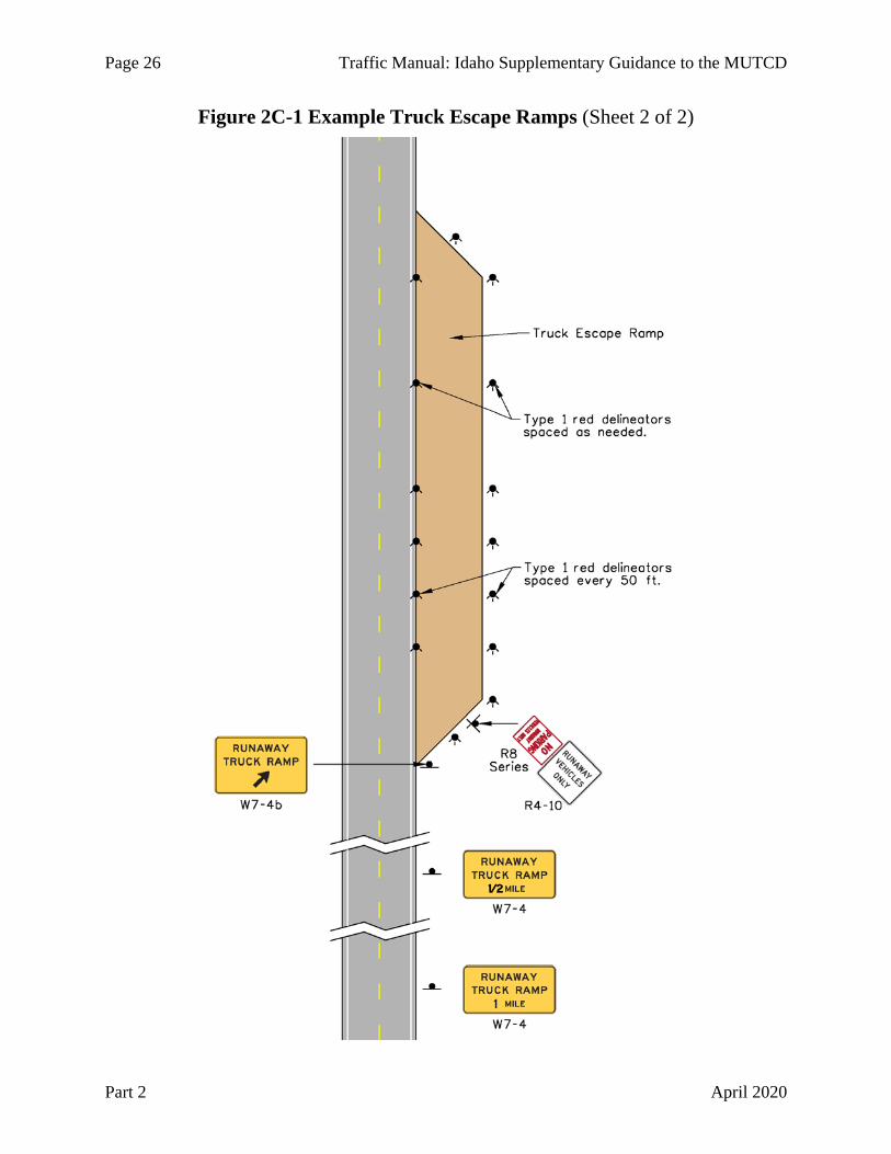
Page 26 Traffic Manual: Idaho Supplementary Guidance to the MUTCD
Part 2 April 2020
Figure 2C-1 Example Truck Escape Ramps (Sheet 2 of 2)
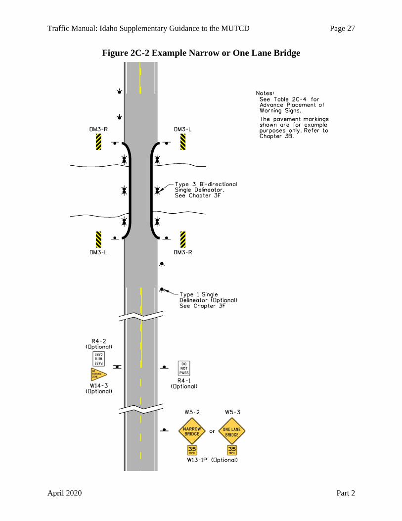
Traffic Manual: Idaho Supplementary Guidance to the MUTCD Page 27
April 2020 Part 2
Figure 2C-2 Example Narrow or One Lane Bridge

Page 28 Traffic Manual: Idaho Supplementary Guidance to the MUTCD
Part 2 April 2020
Section 2C.22 Divided Highway Sign (W6-1)
No supplemental information.
Section 2C.23 Divided Highway Ends Sign (W6-2)
No supplemental information.
Section 2C.24 Freeway or Expressway Ends Signs (W19 Series)
No supplemental information.
Section 2C.25 Double Arrow Sign (W12-1)
No supplemental information.
Section 2C.26 DEAD END/NO OUTLET Signs (W14-1, W14-1a, W14-2, W14-2a)
No supplemental information.
Section 2C.27 Low Clearance Signs (W12-2 and W12-2a)
Use the Low Clearance (W12-2) sign at structures with less than 15 feet of clearance. The statutory maximum vehicle height stated in Idaho Statute 49-1010(2) is 14 feet.
Section 2C.28 BUMP and DIP Signs (W8-1, W8-2)
No supplemental information.
Section 2C.29 SPEED HUMP Sign (W17-1)
No supplemental information.
Section 2C.30 PAVEMENT ENDS Sign (W8-3)
No supplemental information.
Section 2C.31 Shoulder Signs (W8-4, W8-9, W8-17, W8-23, and W8-25)
No supplemental information.
Section 2C.32 Surface Condition Signs (W8-5, W8-7, W8-8, W8-11, W8-13, and W8-14)
Custom surface condition signs may be used with legend messages such as SAND ON ROAD, MUD ON ROAD, WATCH FOR ROCK, SLIDE AREA, SLIDE AHEAD, AVALANCHE AREA, FROST HEAVES, or other similar messages if justified by engineering judgment (see Figure 2C-3). Signs with custom legends should follow the design principles of warning signs.

Traffic Manual: Idaho Supplementary Guidance to the MUTCD Page 29
April 2020 Part 2
Figure 2C-3 Example Roadway Condition Signs
W8 Series
The CHAINS RECOMMENDED WHEN ICY (W8-1301) sign may be used to warn of a surface condition where chains may be preferred (see Figure 2C-4). If used, the sign should be removed or covered during the off seasons. See Section 2I.07 for CHAIN-UP AREA (D5-15 and D5-16) signs and Section 2B.100 for the CHAINS REQUIRED ALL NON-EXEMPT COMMERCIAL VEHICLES (R16-201) sign.

Page 30 Traffic Manual: Idaho Supplementary Guidance to the MUTCD
Part 2 April 2020
Figure 2C-4 Chains Recommended Sign
W8-1301
Section 2C.33 Warning Signs and Plaques for Motorcyclists (W8-15, W8-15P, and W8-16)
No supplemental information.
Section 2C.34 NO CENTER LINE Sign (W8-12)
No supplemental information.
Section 2C.35 Weather Condition Signs (W8-18, W8-19, W8-21, W8-22)
Custom weather condition signs may be used with legend messages such as LOW VISIBILITY AREA, SEVERE STORM AREA, or other similar messages if justified by engineering judgment (see Figure 2C-5). Signs with custom legends should follow the design principles of warning signs.
Figure 2C-5 Example Weather Condition Signs
W8 Series
Section 2C.36 Advance Traffic Control Signs (W3-1, W3-2, W3-3, W3-4)
STOP AHEAD (W3-1) signs may be installed on local public roads in advance of an intersection with a state highway. Coordinate the installation and maintenance of the STOP AHEAD sign with the local road or highway agency (see Section 1A.07).
Follow the MUTCD sign guidance when using an advance warning sign with a warning beacon that is interconnected with a traffic control signal (see Figure 2C-6). Discontinue the use of the following sign in Figure 2C-7.

Traffic Manual: Idaho Supplementary Guidance to the MUTCD Page 31
April 2020 Part 2
Figure 2C-6 MUTCD Signing for Warning Sign with Flashing Beacons
Figure 2C-7 Canadian Signing for Warning Sign with Flashing Beacons
Section 2C.37 Advance Ramp Control Signal Signs (W3-7 AND W3-8)
No supplemental information.
Section 2C.38 Reduced Speed Limit Ahead Signs (W3-5, W3-5a)
No supplemental information.
Section 2C.39 DRAW BRIDGE Sign (W3-6)
No supplemental information.
Section 2C.40 Merge Signs (W4-1, W4-5)
No supplemental information.

Page 32 Traffic Manual: Idaho Supplementary Guidance to the MUTCD
Part 2 April 2020
Section 2C.41 Added Lane Signs (W4-3, W4-6)
No supplemental information.
Section 2C.42 Lane Ends Signs (W4-2, W9-1, W9-2)
The LANE ENDS MERGE LEFT (RIGHT) (W9-2) sign or Lane Ends (W4-2) sign should be installed in accordance with MUTCD Table 2C-4. See Figure 2D-5 for the use of the Lane Ends (W4-2) and RIGHT LANE ENDS (W9-1) signs at passing lanes.
Section 2C.43 RIGHT (LEFT) LANE EXIT ONLY AHEAD Sign (W9-7)
No supplemental information.
Section 2C.44 Two-Way Traffic Sign (W6-3)
No supplemental information.
Section 2C.45 NO PASSING ZONE Sign (W14-3)
No supplemental information.
Section 2C.46 Intersection Warning Signs (W2-1 through W2-8)
No supplemental information.
Section 2C.47 Two-Direction Large Arrow Sign (W1-7)
No supplemental information.
Section 2C.48 Traffic Signal Signs (W25-1, W25-2)
No supplemental information.
Section 2C.49 Vehicular Traffic Warning Signs (W8-6, W11-1, W11-5, W11-5a, W11-8, W11-10, W11-11, W11-12P, W11-14, W11-15, and W11-15a)
Idaho statutes 49-426(4), Board Policy 4070, and Administrative Policy 5070 address the use of all-terrain vehicles (ATVs), utility type vehicles (UTVs), specialty off-highway vehicles (SOHVs), and motorbikes on state highways as follows:
1) Within city limits, and within one mile of city limits, ATVs, UTVs, SOHVs, and motorbikes can travel on non-full access-controlled state highways if the speed limit is 45 mph or less, unless restricted by ITD.
2) Outside city limits (except for one mile beyond city limits), ITD may designate sections of non-full access-controlled state highways to allow ATV, UTV, SOHV, and motorbike use.
3) ATVs, UTVs, SOHVs, and motorbikes can cross non-full access-controlled state highways at public road intersections within and outside of city limits and other locations permitted by ITD.
Support recommendations to allow ATV, UTV, SOHV, or motorbike travel on or crossings of non-full access-controlled highways with an engineering study. The engineering study should consider the following:

Traffic Manual: Idaho Supplementary Guidance to the MUTCD Page 33
April 2020 Part 2
A. Relative speeds of trail and highway users,
B. Relative volumes of trail and highway traffic,
C. Relative importance of trail and highway, and
D. Sight distance available on each approach.
Limit trail crossings to right angles with the highway if practical. Control trail crossings with STOP (R1-1) signs. Place or shield the STOP signs so they are not readily visible to highway users. The TRAIL CROSSING (W11-15a) sign may be used to warn of a location where ATVs, UTVs, SOHVs, and motorbikes might be crossing the highway. Discontinue the use of the RECREATIONAL XING sign.
Manage and track approved ATV, UTV, SOHV, and motorbike crossing points at non-public road intersection as an encroachment permit in accordance with IDAPA 39.03.42 “Rules Governing Highway Right-of-Way Encroachments on state Right-of-Way.” When TRAIL CROSSING signs are installed by permit, include documentation outlining trail signing responsibility in the crossing permit.
Section 2C.50 Non-Vehicular Warning Signs (W11-2, W11-3, W11-4, W11-6, W11-7, W11-9, and W11-16 through W11-22)
Non-vehicular warning signs with symbols are preferred over warning signs with word messages. Warning signs with word messages such as WATCH FOR STOCK or GAME CROSSING should be removed when they are no longer in serviceable condition. Word messages can be tried if symbol warning signs are frequently being vandalized.
See Section 1A.10 and Section 2A.06 for the use of symbols that are not shown in the “Standard Highway Signs and Markings” book.
See Section 2C.53 for the use of the OPEN RANGE (W16-901P) plaque.
Section 2C.51 Playground Sign (W15-1)
No supplemental information.
Section 2C.52 NEW TRAFFIC PATTERN AHEAD Sign (W23-2)
No supplemental information.
Section 2C.53 Use of Supplemental Warning Plaques
The OPEN RANGE (W16-901P) plaque (see Figure 2C-8) may be used with the Cow (W11-4) or Sheep (W11-17) Non-Vehicular Warning signs. Open range is defined in Idaho statute 25-2118 as “all unenclosed lands outside of cities, villages and herd districts, upon which by custom, license, lease, or permit are grazed or permitted to roam.” Idaho statute 25-2402 contains a similar definition. Idaho Statute 49-202(28) requires ITD to provide information about the state’s open range law and the responsibilities, liabilities, and obligations of drivers. The statute does not require the use of the OPEN RANGE plaque, but the plaque may be used in locations determined by engineering judgment.

Page 34 Traffic Manual: Idaho Supplementary Guidance to the MUTCD
Part 2 April 2020
Figure 2C-8 Open Range Plaque
W16-901P
Section 2C.54 Design of Supplemental Warning Plaques
No supplemental information.
Section 2C.55 Distance Plaques (W16-2 Series, W16-3 Series, W16-4P, W7-3aP)
No supplemental information.
Section 2C.56 Supplemental Arrow Plaques (W16-5P, W16-6P)
No supplemental information.
Section 2C.57 Hill-Related Plaques (W7-2 Series, W7-3 Series)
No supplemental information.
Section 2C.58 Advance Street Name Plaque (W16-8P, W16-8aP)
If used, only use in advance of official named intersecting streets.
The advance street name plaque height can be increased to twelve inches and the legend height to six inches to improve conspicuity. See the “ITD Supplement to the Standard Highway Signs and Markings” Book.
Section 2C.59 CROSS TRAFFIC DOES NOT STOP Plaque (W4-4P)
No supplemental information.
Section 2C.60 SHARE THE ROAD Plaque (W16-1P)
No supplemental information.
Section 2C.61 Photo Enforced Plaque (W16-10P)
No supplemental information.
Section 2C.62 NEW Plaque (W16-15P)
No supplemental information.
Section 2C.63 Object Marker Design and Placement Height
Discontinue using the Truck Escape Ramp (OM6) object marker. Replace with red delineators (see MUTCD Chapter 3F).

Traffic Manual: Idaho Supplementary Guidance to the MUTCD Page 35
April 2020 Part 2
Section 2C.64 Object Markers for Obstructions Within the Roadway
No supplemental information.
Section 2C.65 Object Markers for Obstructions Adjacent to the Roadway
No supplemental information.
Section 2C.66 Object Markers for Ends of Roadways
No supplemental information.
Section 2C.100 Radar Speed Feedback Changeable Message Signs (Section is not in the MUTCD)
This section supplements MUTCD Section 2B.13, paragraphs 19 through 20, and MUTCD Chapter 2L.
If a radar speed feedback changeable message sign is used, the sign must be rectangular and have a black legend and border on a yellow background (see Figure 2C-9). The changeable message portion of the sign must have a yellow legend on a black background displaying the speed value with not less than 20 mm pitch LEDs covering the stroke width of a 10 inch series numeral. Display the legend YOUR SPEED XX on the sign. Do not display word messages, animation, strobe lights, rapid flashing, dissolving, exploding, scrolling, or other dynamic elements within the changeable message portion of the sign.
The sign dimensions and legend size must match those of the Speed Limit (R2-1) sign. See the design details for the radar speed feedback changeable message sign in the “ITD Supplement to the Standard Highway Signs and Markings” book.
The sign can be installed on the same post under a Speed Limit (R2-1) sign (provided the height still meets MUTCD Section 2A.16) or on its own post. The sign dimensions must be smaller than or equal to the regulatory Speed Limit (R2-1) sign used in the vicinity of the installation.

Page 36 Traffic Manual: Idaho Supplementary Guidance to the MUTCD
Part 2 April 2020
Figure 2C-9 Example Radar Speed Feedback Changeable Message Sign
W13-100

Traffic Manual: Idaho Supplementary Guidance to the MUTCD Page 37
April 2020 Part 2
CHAPTER 2D. GUIDE SIGNS – CONVENTIONAL ROADS Section 2D.01 Scope of Conventional Road Guide Sign Standards
No supplemental information.
Section 2D.02 Application
No supplemental information.
Section 2D.03 Color, Retroreflection, and Illumination
No supplemental information.
Section 2D.04 Size of Signs
Round sign heights up to twelve inch increments when the signs are constructed with extruded aluminum panels. ITD prefers to use twelve inch extruded aluminum panels.
Section 2D.05 Lettering Style
No supplemental information.
Section 2D.06 Size of Lettering
No supplemental information.
Section 2D.07 Amount of Legend
No supplemental information.
Section 2D.08 Arrows
See the detailed drawings in the “ITD Supplement to the Standard Highway Signs and Markings” book for additional arrow dimensions (see Section 1A.11).
Section 2D.09 Numbered Highway Systems
No supplemental information.
Section 2D.10 Route Signs and Auxiliary Signs
No supplemental information.
Section 2D.11 Design of Route Signs
The Idaho State Route sign is a square or rectangle with black numerals in the top right corner and a black depiction of the shape of Idaho in the bottom left corner on a white retroreflective background (see Figure 2D-1). The same sign design is used for route sign auxiliaries and as guide sign components.
Discontinue the use of prior Idaho State Route sign designs. Signs with prior designs may remain as long as they are in serviceable condition.

Page 38 Traffic Manual: Idaho Supplementary Guidance to the MUTCD
Part 2 April 2020
Figure 2D-1 Idaho Route Signs
M1-5 (1 or 2-digit) M1-5 (3-digit)
See Section 2D.29 for the use of the County Route Sign (M1-6) and the Forest Route Sign (M1-7).
Section 2D.12 Design of Route Sign Auxiliaries
No supplemental information.
Section 2D.13 Junction Auxiliary Sign (M2-1)
No supplemental information.
Section 2D.14 Combination Junction Sign (M2-2)
No supplemental information.
Section 2D.15 Cardinal Direction Auxiliary Signs (M3-1 through M3-4)
No supplemental information.
Section 2D.16 Auxiliary Signs for Alternative Routes (M4 Series)
No supplemental information.
Section 2D.17 ALTERNATE Auxiliary Signs (M4-1, M4-1a)
No supplemental information.
Section 2D.18 BY-PASS Auxiliary Sign (M4-2)
No supplemental information.
Section 2D.19 BUSINESS Auxiliary Sign (M4-3)
No supplemental information.
Section 2D.20 TRUCK Auxiliary Sign (M4-4)
No supplemental information.
Section 2D.21 TO Auxiliary Sign (M4-5)
No supplemental information.

Traffic Manual: Idaho Supplementary Guidance to the MUTCD Page 39
April 2020 Part 2
Section 2D.22 END Auxiliary Sign (M4-6)
No supplemental information.
Section 2D.23 BEGIN Auxiliary Sign (M4-14)
No supplemental information.
Section 2D.24 TEMPORARY Auxiliary Sign (M4-7, M4-7a)
No supplemental information.
Section 2D.25 Temporary Detour and Auxiliary Signs
No supplemental information.
Section 2D.26 Advance Turn Arrow Auxiliary Signs (M5-1, M5-2, and M5-3)
No supplemental information.
Section 2D.27 Lane Designation Auxiliary Signs (M5-4, M5-5, and M5-6)
No supplemental information.
Section 2D.28 Directional Arrow Auxiliary Signs (M6 Series)
No supplemental information.
Section 2D.29 Route Sign Assemblies
A County Route Sign or Forest Route Sign assembly, consisting of the route sign and auxiliary signs, may be installed on U.S. or State numbered routes.
Section 2D.30 Junction Assembly
No supplemental information.
Section 2D.31 Advance Route Turn Assembly
No supplemental information.
Section 2D.32 Directional Assembly
No supplemental information.
Section 2D.33 Combination Lane-Use/Destination Overhead Guide Sign (D15-1)
No supplemental information.
Section 2D.34 Confirming or Reassurance Assemblies
Route signs for confirming or reassurance purposes should be placed every 10 miles between interstate interchanges and at 5 mile intervals between cities in rural areas on other highways.
Section 2D.35 Trailblazer Assembly
Unless an agreement is made with a local agency, ITD will not provide, place, or maintain trailblazer assemblies directing motorists to an ITD highway on local agency roads.
Page 40 Traffic Manual: Idaho Supplementary Guidance to the MUTCD
Part 2 April 2020
Section 2D.36 Destination and Distance Signs
No supplemental information.
Section 2D.37 Destination Signs (D1 Series)
If destination signs are used, display the names of cities along the highway that are regional destinations. Figure 2D-2 shows example destination cities and control cities. Other cities may be displayed based on engineering judgment. See Section 2E.13 for control city information.
Section 2D.38 Destination Signs at Circular Intersections
No supplemental information.
Section 2D.39 Destination Signs at Jughandles
No supplemental information.
Section 2D.40 Location of Destination Signs
An additional destination sign may be placed at the top of a “T” intersection where approaching vehicles must stop.
Section 2D.41 Distance Signs (D2 Series)
Display distances to the well-defined central area or central business district of destination cities (see Section 2D.37). If a central area is not well defined, measure distances to the main post office of the city in question.
See Section 2E.13 for control city information.
Section 2D.42 Location of Distance Signs
If used, also install distance signs near state lines and significant traffic generators as determined by engineering judgment.
If used, place distance signs at 20 mile intervals or less.
Section 2D.43 Street Name Signs (D3-1 or D3-1a)
In accordance with IDAPA 39.03.41 “Rules Governing Traffic Control Devices,” do not omit sign borders from Street Name signs on the State Highway System or related highways.
When installed on a highway traffic signal mast arm, install the Street Name (D3-1 or D3-1a) sign 2 feet to the right of the furthest right signal head.
Street Name (D3-1 or D3-1a) signs may be installed and maintained on a separate breakaway post by other agencies in ITD right-of-way through a written agreement or permit.
Section 2D.44 Advance Street Name Signs (D3-2)
No supplemental information.

Traffic Manual: Idaho Supplementary Guidance to the MUTCD Page 41
April 2020 Part 2
Figure 2D-2 Control Cities and Example Destination Cities

Page 42 Traffic Manual: Idaho Supplementary Guidance to the MUTCD
Part 2 April 2020
Section 2D.45 Signing on Conventional Roads on Approaches to Interchanges
Show control city destinations on the approaches to interstate highway interchanges (see Section 2E.13). Show destination cities on the approaches to non-interstate highway interchanges (see Section 2D.41).
Section 2D.46 Freeway Entrance Signs (D13-3 and D13-3a)
No supplemental information.
Section 2D.47 Parking Area Guide Sign (D4-1)
No supplemental information.
Section 2D.48 PARK – RIDE Sign (D4-2)
No supplemental information.
Section 2D.49 Weigh Station Signing (D8 Series)
Figure 2D-4 shows example locations of the D8 series signs with the TRUCKS OVER 26,000 AND LIVESTOCK-HAZMAT HAULERS OVER 10,000 MUST STOP (R13-101) sign.
Section 2D.50 Community Wayfinding Signs
No supplemental information.
Section 2D.51 Truck, Passing, or Climbing Lane Signs (D17-1 and D17-2)
See Figure 2D-5 for the use of the NEXT TRUCK LANE XX (D17-1) and PASSING LANE XX MILES (D17-2) signs at passing lanes. The distances shown on the passing lane signs are for example purposes only.
Section 2D.52 Slow Vehicle Turn-Out Sign (D17-7)
In addition to the SLOW VEHICLE TURN-OUT XX MILES (D17-7) sign, a SLOW VEHICLE TURN-OUT sign (D17-701, see Figure 2D-3) with a directional arrow may be used immediately before the turn-out.
Figure 2D-3 Slow Vehicle Turn-Out Sign
D17-701

Traffic Manual: Idaho Supplementary Guidance to the MUTCD Page 43
April 2020 Part 2
Figure 2D-4 Example of Weigh Station Signing

Page 44 Traffic Manual: Idaho Supplementary Guidance to the MUTCD
Part 2 April 2020
Figure 2D-5 Example Passing Lane Signs and Markings

Traffic Manual: Idaho Supplementary Guidance to the MUTCD Page 45
April 2020 Part 2
Section 2D.53 Signing of Named Highways
See MUTCD Section 2M.10 for memorial highways and bridges.
Section 2D.54 Crossover Signs (D13-1 and D13-2)
No supplemental information.
Section 2D.55 National Scenic Byways Signs (D6-4, D6-4a)
There are six National Scenic Byways in Idaho. They are the International Selkirk Loop, the Northwest Passage Scenic Byway, the Payette River Scenic Byway, the Pend Oreille Scenic Byway, the Pioneer Historic Byway, and the Western Heritage Historic Byway. The National Scenic Byways (D6-4 or D6-4a) signs, signs specific to that scenic byway, or both may be installed in accordance with the MUTCD.
In addition to the six National Scenic Byways in Idaho, the Idaho Transportation Board has designated Idaho Byways (see Board Policy 4082 and Administrative policy 5082). State-designated named scenic byways are a type of auto tour route and are addressed in Section 2H.07 of the MUTCD and this manual.
Section 2D.100 Trip Permits Signs (Section is not in the MUTCD)
Guide signs (D20 series) may be used on non-interstate highways or on streets in the vicinity of Interstate highways to direct heavy vehicles to approved trip permit vendors (see Figure 2D-6).
Figure 2D-6 Example Trip Permit Signs
D20-1 D20-2 D20-3

Page 46 Traffic Manual: Idaho Supplementary Guidance to the MUTCD
Part 2 April 2020
CHAPTER 2E. GUIDE SIGNS – FREEWAYS AND EXPRESSWAYS Section 2E.01 Scope of Freeway and Expressway Guide Sign Standards
No supplemental information.
Section 2E.02 Freeway and Expressway Signing Principles
No supplemental information.
Section 2E.03 Guide Sign Classification
No supplemental information.
Section 2E.04 General
No supplemental information.
Section 2E.05 Color of Guide Signs
No supplemental information.
Section 2E.06 Retroreflection or Illumination
No supplemental information.
Section 2E.07 Characteristics of Urban Signing
No supplemental information.
Section 2E.08 Characteristics of Rural Signing
No supplemental information.
Section 2E.09 Signing of Named Highways
No supplemental information.
Section 2E.10 Amount of Legend on Guide Signs
No supplemental information.
Section 2E.11 Number of Signs at an Overhead Installation and Sign Spreading
No supplemental information.
Section 2E.12 Pull-Through Signs (E6-2, E6-2a)
No supplemental information.
Section 2E.13 Designation of Destinations
AASHTO maintains a list of control cities to use on Interstate highway guide signs and on guide signs on the conventional road approaches to Interstate highway interchanges (see Section 2D.45). The control cities for Interstate highways in Idaho and adjoining states are shown in Table 2E-1 and on Figure 2D-2.

Traffic Manual: Idaho Supplementary Guidance to the MUTCD Page 47
April 2020 Part 2
Table 2E-1 Interstate Control Cities
Interstate Control Cities
15 Salt Lake City, Ogden, Pocatello, Idaho Falls, Butte
84 Portland, Ontario, Boise, Twin Falls, Ogden
86 Pocatello
90 Spokane, Coeur d’Alene, Missoula
Display up to two control cities on guide signs. Avoid displaying a city name and a street name on the same sign (see MUTCD Section 2E.10). Where more than one control city is displayed, first show the closest control city in the direction of travel and then the next major destination. The following are examples of this principle:
• Display Ontario and Portland on westbound I-84 west of Boise
• Display Ogden and Salt Lake City on southbound I-15 south of Pocatello
Do not display destinations that are not control cities.
See the “AASHTO Guidelines for Supplemental Guide Signing” for additional information. The full list of Interstate control cities can be found on the AASHTO Committee on Traffic Engineering website. ITD headquarters will make requests to change control cities in Idaho on behalf of ITD.
Section 2E.14 Size and Style of Letters and Signs
Round sign heights up to twelve inch increments when the signs are constructed with extruded aluminum panels. ITD prefers to use twelve inch extruded aluminum panels.
Section 2E.15 Interline and Edge Spacing
No supplemental information.
Section 2E.16 Sign Borders
No supplemental information.
Section 2E.17 Abbreviations
No supplemental information.
Section 2E.18 Symbols
No supplemental information.
Section 2E.19 Arrows for Interchange Guide Signs
See the detailed drawings in the “ITD Supplement to the Standard Highway Signs and Markings” book for additional arrow dimensions (see Section 1A.11).

Page 48 Traffic Manual: Idaho Supplementary Guidance to the MUTCD
Part 2 April 2020
Section 2E.20 Signing for Option Lanes at Splits and Multi-Lane Exits
No supplemental information.
Section 2E.21 Design of Overhead Arrow-per-Lane Guide Signs for Option Lanes
No supplemental information.
Section 2E.22 Design of Freeway and Expressway Diagrammatic Guide Signs for Option Lanes
No supplemental information.
Section 2E.23 Signing for Intermediate and Minor Interchange Multi-Lane Exits with an Option Lane
Use Figure 2E-1 instead of Figure 2E-11 from the MUTCD.
Section 2E.24 Signing for Interchange Lane Drops
No supplemental information.
Section 2E.25 Overhead Sign Installations
No supplemental information.
Section 2E.26 Lateral Offset
No supplemental information.
Section 2E.27 Route Signs and Trailblazer Assemblies
No supplemental information.
Section 2E.28 Eisenhower Interstate System Signs (M1-10, M1-10a)
No supplemental information.

Traffic Manual: Idaho Supplementary Guidance to the MUTCD Page 49
April 2020 Part 2
Figure 2E-1 Example of Signing for a Two-Lane Exit with an Option Lane

Page 50 Traffic Manual: Idaho Supplementary Guidance to the MUTCD
Part 2 April 2020
Section 2E.29 Signs for Intersections at Grade
No supplemental information.
Section 2E.30 Interchange Guide Signs
No supplemental information.
Section 2E.31 Interchange Exit Numbering
See IDAPA 39.03.41 “Rules Governing Traffic Control Devices” for modifications to paragraph 02.
Exit Number (E1-5P) and Left Exit Number (E1-5bP) plaques must have borders on each side and be at least the width shown in Table 2E-1 of the MUTCD. The E1-5P plaques are to be 36 inches in height and the E1-5bP plaques are to be 60 inches in height. The plaque heights are increased by six inches so that twelve inch extruded aluminum panels can be used to make the plaque. See the design details for the E1-5P and E1-5bP plaques in the “ITD Supplement to the Standard Highway Signs and Markings” book.
Section 2E.32 Interchange Classification
No supplemental information.
Section 2E.33 Advance Guide Signs
No supplemental information.
Section 2E.34 Next Exit Plaques
No supplemental information.
Section 2E.35 Other Supplemental Guide Signs
Refer to the “AASHTO Guidelines for Supplemental Guide Signing” publication as the ITD policy for installing supplemental guide signs.
Section 2E.36 Exit Direction Signs
No supplemental information.
Section 2E.37 Exit Gore Signs (E5-1 Series)
No supplemental information.
Section 2E.38 Post-Interchange Signs
No supplemental information.
Section 2E.39 Post-Interchange Distance Signs
See Section 2D.41 for control city information.
Section 2E.40 Interchange Sequence Signs
No supplemental information.

Traffic Manual: Idaho Supplementary Guidance to the MUTCD Page 51
April 2020 Part 2
Section 2E.41 Community Interchanges Identification Signs
No supplemental information.
Section 2E.42 NEXT XX EXITS Sign
No supplemental information.
Section 2E.43 Signing by Type of Interchange
No supplemental information.
Section 2E.44 Freeway-to-Freeway Interchange
See Section 2D.41 for control city information.
Section 2E.45 Cloverleaf Interchange
No supplemental information.
Section 2E.46 Cloverleaf Interchange with Collector-Distributor Roadways
No supplemental information.
Section 2E.47 Partial Cloverleaf Interchange
No supplemental information.
Section 2E.48 Diamond Interchange
No supplemental information.
Section 2E.49 Diamond Interchange in Urban Area
No supplemental information.
Section 2E.50 Closely-Spaced Interchanges
No supplemental information.
Section 2E.51 Minor Interchange
No supplemental information.
Section 2E.52 Signing on Conventional Road Approaches and Connecting Roadways
No supplemental information.
Section 2E.53 Wrong-Way Traffic Control at Interchange Ramps
No supplemental information.
Section 2E.54 Weigh Station Signing
No supplemental information.

Page 52 Traffic Manual: Idaho Supplementary Guidance to the MUTCD
Part 2 April 2020
CHAPTER 2F. TOLL ROAD SIGNS Section 2F.01 Scope
No supplemental information.
Section 2F.02 Sizes of Toll Road Signs
No supplemental information.
Section 2F.03 Use of Purple Backgrounds and Underlay Panels with ETC Account Pictographs
No supplemental information.
Section 2F.04 Size of ETC Pictographs
No supplemental information.
Section 2F.05 Regulatory Signs for Toll Plazas
No supplemental information.
Section 2F.06 Pay Toll Advance Warning Sign (W9-6)
No supplemental information.
Section 2F.07 Pay Toll Advance Warning Plaque (W9-6P)
No supplemental information.
Section 2F.08 Stop Ahead Pay Toll Warning Sign (W9-6a)
No supplemental information.
Section 2F.09 Stop Ahead Pay Toll Warning Plaque (W9-6aP)
No supplemental information.
Section 2F.10 LAST EXIT BEFORE TOLL Warning Plaque (W16-P)
No supplemental information.
Section 2F.11 TOLL Auxiliary Sign (M4-15)
No supplemental information.
Section 2F.12 Electronic Toll Collection (ETC) Account-Only Auxiliary Signs (M4-16 and M4-20
No supplemental information.
Section 2F.13 Toll Facility and Toll Plaza Guide Signs - General
No supplemental information.

Traffic Manual: Idaho Supplementary Guidance to the MUTCD Page 53
April 2020 Part 2
Section 2F.14 Advance Signs for Conventional Toll Plazas
No supplemental information.
Section 2F.15 Advance Signs for Toll Plazas on Diverging Alignments from Open-Road ETC Account-Only Lanes
No supplemental information.
Section 2F.16 Toll Plaza Canopy Signs
No supplemental information.
Section 2F.17 Guide Signs for Entrances to ETC Account-Only Facilities
No supplemental information.
Section 2F.18 ETC Program Information Signs
No supplemental information.
CHAPTER 2G. PREFERENTIAL AND MANAGED LANE SIGNS Section 2G.01 Scope
No supplemental information.
Section 2G.02 Sizes of Preferential and Managed Lane Signs
No supplemental information.
Section 2G.03 Regulatory Signs for Preferential Lanes - General
No supplemental information.
Section 2G.04 Preferential Lane Vehicle Occupancy Definition Regulatory Signs (R3-10 Series and R3-13 Series)
No supplemental information.
Section 2G.05 Preferential Lane Periods of Operation Regulatory Signs (R3-11 and R3-14 Series)
No supplemental information.
Section 2G.06 Preferential Lane Advance Regulatory Signs (R3-12, R3-12e, R3-12f, R3-15a, and R3-15d)
No supplemental information.
Section 2G.07 Preferential Lane Ends Regulatory Signs (R3-12a, R3-12b, R3-12c, R3-12d, R3-12g, R3-12h, R3-15b, R3-15c, and R3-15e)
No supplemental information.

Page 54 Traffic Manual: Idaho Supplementary Guidance to the MUTCD
Part 2 April 2020
Section 2G.08 Warning Signs on Median Barriers for Preferential Lanes
No supplemental information.
Section 2G.09 High-Occupancy Vehicle (HOV) Plaque (W16-11P)
No supplemental information.
Section 2G.10 Preferential Lane Guide Signs - General
No supplemental information.
Section 2G.11 Guide Signs for Initial Entry Points to Preferential Lanes
No supplemental information.
Section 2G.12 Guide Signs for Intermediate Entry Points to Preferential Lanes
No supplemental information.
Section 2G.13 Guide Signs for Egress from Preferential Lanes to General-Purpose Lanes
No supplemental information.
Section 2G.14 Guide Signs for Direct Entrances to Preferential Lanes from Another Highway
No supplemental information.
Section 2G.15 Guide Signs for Direct Exits from Preferential Lanes to Another Highway
No supplemental information.
Section 2G.16 Signs for Priced Managed Lanes - General
No supplemental information.
Section 2G.17 Regulatory Signs for Priced Managed Lanes
No supplemental information.
Section 2G.18 Guide Signs for Priced Managed Lanes
No supplemental information.

Traffic Manual: Idaho Supplementary Guidance to the MUTCD Page 55
April 2020 Part 2
CHAPTER 2H. GENERAL INFORMATION SIGNS Section 2H.01 Size of General Information Signs
No supplemental information.
Section 2H.02 General Information Signs (I Series)
Political entities may install custom political boundary General Information signs in lieu of ITD provided boundary signs by permit (also see Section 2H.04). Permitted custom political boundary signs must be provided, installed, and maintained by the political entity requesting the sign. Comply with the general provisions for signs described in CHAPTER 2A for political boundary sign design and installation. Do not include the names of elected officials or variable message panels on the sign.
Section 2H.03 Traffic Signal Speed Sign (I1-1)
No supplemental information.
Section 2H.04 Miscellaneous Information Signs
Use a combination of lower-case letters with initial upper-case letters for names of places, streets, and highways. See MUTCD Section 2A.13.
Following the guidance in Section 2H.04, political boundary signs may include text denoting the political boundary (city limit, county line, etc.), that the highway user is entering or leaving a political jurisdiction, and the population. Use the WELCOME TO IDAHO (I-201) or IDAHO STATE LINE (I-2) sign near state boundaries (see Figure 2H-1). Use political boundary signs at the boundaries of reservations and National Forests. Because they have no political boundaries, unincorporated communities are usually not signed.
Figure 2H-1 Idaho Boundary Signs
I-201 I-2
IDAPA 39.03.61 “Rules Governing Directional & Other Official Signs & Notices” provides guidance for “Community Official Signs.” These are signs approved by a city, erected within its territorial or zoning jurisdiction and maintained at city expense. The sign legend is limited to the name of the city and driver directional information. The rule gives limits on the placement and size of the signs.
If a city does not provide a “Community Official Sign,” ITD may provide boundary (I-2 series) signs. Examples of boundary signs for counties, cities, and reservations are shown in

Page 56 Traffic Manual: Idaho Supplementary Guidance to the MUTCD
Part 2 April 2020
Figure 2H-2. If a population is shown, use population values from the Idaho Labor Market Information website (http://lmi.idaho.gov). Population values may be updated by ITD districts after the release of a census or at the request of a political entity. If requested by a political entity, use the population estimates from the Idaho Labor Market Information website. Updated signs resulting from requests should be paid for by the political entity requesting the update.
Figure 2H-2 Example Boundary Signs
I-2 Series
Some political jurisdictions have received recognition for the community and desire to publicize the recognition with a sign near the entrance to the community. Such signs may include messages recognizing the community as a Gem Community, an Idaho Heritage City, a Tree City, or a Storm Ready County (see Figure 2H-3).
Figure 2H-3 Example Recognition Signs
Often the signs are supplied to the political jurisdiction receiving the recognition or created by the political jurisdiction. ITD prefers that such signs be installed and maintained by the political jurisdiction outside of the highway right-of-way. Signs recognizing communities may be installed below boundary signs in the highway right-of-way at the discretion of the District Engineer. If installed below a boundary sign, the recognition sign should be addressed in a Cooperative Maintenance Agreement between ITD and the political jurisdiction. Do not install

Traffic Manual: Idaho Supplementary Guidance to the MUTCD Page 57
April 2020 Part 2
community recognition signs on Interstate highways. A community recognition sign should not be installed by itself in the highway right-of-way. Signs installed within the highway right-of-way without the consent of ITD should be removed and returned to the political jurisdiction.
If used, TREE CITY USA signs are only installed for cities listed on the Arbor Day Foundation’s website.
If used, STORM READY signs are only installed for sites listed on the National Weather Service’s website.
IDAPA 39.03.61 “Rules Governing Directional & Other Official Signs & Notices” provides guidance for “Bypassed Community Signs.” When a city has been bypassed, but is within five miles of an interstate highway or other highway, the city may be permitted to install and maintain a sign showing the city name at city expense. The sign should be similar in design to the D1-1 destination sign. Examples of bypassed community signs are shown in Figure 2H-4.
Figure 2H-4 Example Bypassed Community Signs
D1-101
Following the guidance in Section 2H.04, the I-3 sign may be used to point out geographical features such as rivers and summits. If used, the elevation of vertical features like summits can be shown on the sign. Alternate legends such as HILL, CREEK, or CANAL may also be used (see Figure 2H-5).
Figure 2H-5 Example Geographical Features Signs
I-3 Series
Time zone boundaries, lines of latitude, or other features may be indicated with a miscellaneous information sign (see Figure 2H-6).

Page 58 Traffic Manual: Idaho Supplementary Guidance to the MUTCD
Part 2 April 2020
Figure 2H-6 Miscellaneous Information Signs
I -3 Series
Section 2H.05 Reference Location Signs (D10-1 through D10-3) and Intermediate Reference Location Signs (D10-1a through D10-3a)
Install Reference Location (D10-1, 2, and 3) signs, also known as milepost signs, on all numbered highways. The ITD Planning Services Section is responsible for the linear referencing system. Use the ITD-2185 form to record new milepost sign locations and ITD-2184 to request milepost renumbering.
ITD designates the 12 inch wide sign as a Type I milepost assembly. The 10 inch wide sign is designated as a Type II milepost assembly. A Type III assembly is two 10 wide milepost signs installed back to back. See the ITD Milepost Assemblies Standard Drawing.
Discontinuities in distance numbering can be indicated with a milepost equation sign. If used, turn the sign face parallel to the traveled way and offset the sign from the highway as far as possible.
Section 2H.06 Enhanced Reference Location Signs (D10-4, D10-5)
No supplemental information.
Section 2H.07 Auto Tour Route Signs
Four National Historic Trails pass through Idaho. They are the California, Lewis and Clark, Nez Perce, and Oregon National Historic Trails. ITD and the National Park Service have Memorandums of Understanding to provide auto tour signs for the Oregon and California trails (see Figure 2H-7).
The Oregon Trail has two branches, the South Alternate and Goodale’s Cutoff, in addition to its main line. If trail signs are used, a supplemental plaque can be used to indicate the branch of the Oregon Trail (see Figure 2H-8). Because Goodale’s Cutoff is not part of the Oregon National Historic Trail, the sign legend should not designate it as an Auto Tour Route.
The Lewis and Clark and Nez Perce National Historic Trails can also be signed (see Figure 2H-9)

Traffic Manual: Idaho Supplementary Guidance to the MUTCD Page 59
April 2020 Part 2
Figure 2H-7 Example Auto Tour Route Signs
Figure 2H-8 Example Supplementary Plaques
Figure 2H-9 Example National Historic Trail Signs
In addition to the six National Scenic Byways in Idaho (see Section 2D.55), the Idaho Transportation Board has designated several Idaho Byways (see Board Policy 4082 and Administrative policy 5082). Idaho Byways are designated as a State Scenic Byway, Historic Byway, or Back Country Byway.
Install Idaho Byway signs (see Figure 2H-10) in the same manner as directed for the D6-4 or D6-4a National Scenic Byway signs. Install Scenic Byway signs beneath the first route sign encountered on the designated scenic route and beneath route signs throughout the length of the byway.

Page 60 Traffic Manual: Idaho Supplementary Guidance to the MUTCD
Part 2 April 2020
Figure 2H-10 Example Idaho Byway Signs
D6-401 Series
Install Idaho Byway signs with route signs from top to bottom in the following order (see Figure 2H-11):
• Route sign (with cardinal direction auxiliary sign plaque if applicable) • Idaho Byway sign (D6-401 series) • Direction Arrow auxiliary sign (if applicable)
Discontinue the use of the IDAHO BYWAY (previously numbered D7-10) sign. The IDAHO BYWAY sign was previously used as a substitute for the brown State Route sign (M1-5) that is no longer used.

Traffic Manual: Idaho Supplementary Guidance to the MUTCD Page 61
April 2020 Part 2
Figure 2H-11 Example Scenic Byway Assembly
Informational signs describing the scenic byway may be placed at the ends of designated scenic byways in turn-out areas (see Figure 2H-12). These signs are not traffic control devices and should be located outside of the clear zone and where they will not interfere with traffic operations.
A BYWAY INFORMATION AHEAD (D5-2001) sign (see Figure 2H-13) can be installed in advance of the byway information sign and a D5-2101 sign (see Figure 2H-13) can be placed at the entrance to the turnout area.
Figure 2H-12 Example Scenic Byway Informational Sign

Page 62 Traffic Manual: Idaho Supplementary Guidance to the MUTCD
Part 2 April 2020
Figure 2H-13 Byway Information Signs
D5-2001 D5-2101
Section 2H.08 Acknowledgement Signs
ITD has chosen to use its own adopt a highway acknowledgement (D14-101) sign design (see Figure 2H-14). If used, the sign may be placed back-to-back with another acknowledgement sign where there are two adjoining adopt a highway segments.
Figure 2H-14 Adopt A Highway Sign
D14-101
Traffic Manual: Idaho Supplementary Guidance to the MUTCD Page 63
April 2020 Part 2
CHAPTER 2I. GENERAL SERVICE SIGNS Section 2I.01 Size of General Information Signs
No supplemental information.
Section 2I.02 General Service Signs for Conventional Roads
Use paragraph 22 as the State guidelines for the use of the Emergency Medical Services symbol sign in Idaho.
Section 2I.03 General Service Signs for Freeways and Expressways
Use paragraph 06 as the statewide policy for the criteria for the use of General Service signs on Freeways and Expressways.
General Service (D9-18 series) signs are generally not used when Specific Service signs are used or in advance of a Business Route (see Section 2D.11).
The services shown on a General Service sign are usually limited to those within three miles of the freeway exit.
Section 2I.04 Interstate Oasis Signing
ITD has instituted Board Policy 4044 – Safety Rest Areas and Oasis Partnerships – and Administrative Policy 5044 – Safety Rest Areas and Oasis Partnerships. Businesses can enter into a cooperative agreement with ITD to be designated and signed as an Interstate Oasis.
Trailblazer guide signs along the crossroad to guide road users to an Interstate Oasis will be provided by others unless otherwise agreed in the cooperative agreement.
Section 2I.05 Rest Area and Other Roadside Area Signs
Information can be provided on the location of succeeding rest areas using the NEXT REST AREA XX MILES (D5-6) sign, but similar signing should not be used in advance of an Interstate Oasis.
Section 2I.06 Brake Check Area Signs (D5-13 and D5-14)
No supplemental information.
Section 2I.07 Chain-Up Area Signs (D5-15 and D5-16)
When the CHAINS REQUIRED ALL NON-EXEMPT COMMERCIAL VEHICLES (R16-201) sign is used (See Section 2B.100 of the Traffic Manual), the CHAIN-UP AREA (D5-16) sign must be used in accordance with Idaho Statute 49-948.
If used, CHAIN-UP AREA signs should be removed or covered during the off seasons.
Discontinue the use of the green CHAIN UP AREA sign.
Section 2I.08 Tourist Information and Welcome Center Signs
VISITOR INFO may be used on the legend of the sign instead of TOURIST INFO or WELCOME CENTER.

Page 64 Traffic Manual: Idaho Supplementary Guidance to the MUTCD
Part 2 April 2020
Do not use tourist information and welcome center signs if the information or center is located further than five miles from an interchange.
If used, signing along a crossroad to guide the road user from an interchange to the tourist information center and back to the interchange will be installed by a local political jurisdiction.
Section 2I.09 Radio Information Signing
The REPORT DRUNK DRIVING CALL *ISP (D12-401) sign or REPORT WILDFIRES # FIRE (D12-402) sign may be used for cellular phone communications (see Figure 2I-1).
Figure 2I-1 Telephone Information Signs
D12-401 D12-402
Section 2I.10 TRAVEL INFO CALL 511 Signs (D12 and D12-5a)
No supplemental information.
Section 2I.11 Carpool and Ridesharing Signing
No supplemental information.

Traffic Manual: Idaho Supplementary Guidance to the MUTCD Page 65
April 2020 Part 2
CHAPTER 2J. SPECIFIC SERVICE SIGNS Section 2J.01 Eligibility
No supplemental information.
Section 2J.02 Application
No supplemental information.
Section 2J.03 Logos and Logo Sign Panels
No supplemental information.
Section 2J.04 Number and Size of Signs and Logo Sign Panels
No supplemental information.
Section 2J.05 Size of Lettering
No supplemental information.
Section 2J.06 Signs at Interchanges
No supplemental information.
Section 2J.07 Single-Exit Interchanges
No supplemental information.
Section 2J.08 Double-Exit Interchanges
No supplemental information.
Section 2J.09 Specific Service Trailblazer Signs
No supplemental information.
Section 2J.10 Signs at Intersections
No supplemental information.
Section 2J.11 Signing Policy
ITD has established a signing policy through IDAPA 39.03.41 - Rules Governing Traffic Control Devices which references the ITD document Standards and Procedures for Specific Service Signs.

Page 66 Traffic Manual: Idaho Supplementary Guidance to the MUTCD
Part 2 April 2020
CHAPTER 2K. TOURIST-ORIENTED DIRECTIONAL SIGNS Section 2K.01 Purpose and Application No supplemental information.
Section 2K.02 Design No supplemental information.
Section 2K.03 Style and Size of Lettering No supplemental information.
Section 2K.04 Arrangement and Size of Signs No supplemental information.
Section 2K.05 Advance Signs No supplemental information.
Section 2K.06 Sign Locations No supplemental information.
Section 2K.07 State Policy
ITD has established a signing policy through IDAPA 39.03.41 - Rules Governing Traffic Control Devices which references the ITD document Standards and Procedures for Tourist Oriented Direction Signs (TODS).
CHAPTER 2L. CHANGEABLE MESSAGE SIGNS Section 2L.01 Description of Changeable Message Signs See Chapter 16B for additional information on Changeable Message Signs (CMS).
Section 2L.02 Applications of Changeable Message Signs No supplemental information.
Section 2L.03 Legibility and Visibility of Changeable Message Signs No supplemental information.
Section 2L.04 Design Characteristics of Changeable Message Signs No supplemental information.
Section 2L.05 Message Length and Units of Information No supplemental information.
Section 2L.06 Installation of Permanent Changeable Message Signs No supplemental information.

Traffic Manual: Idaho Supplementary Guidance to the MUTCD Page 67
April 2020 Part 2
CHAPTER 2M. RECREATIONAL AND CULTURAL INTEREST AREA SIGNS Section 2M.01 Scope
ITD has memorandums of understanding (MOU) with the U.S. Forest Service regarding signing responsibilities of highways passing through National Forests. ITD has responsibility for the following signing:
• Interstate Highways
o All signing
• Other Highways
o Warning and regulatory signs
o Route markers, designation guide signs, and reference location signs
o Pedestrian control devices
o Temporary traffic control devices for ITD construction and maintenance activities
The Forest Service has responsibility for the following signing:
• National Forest boundary signs
• Guard stations and administrative sites
• Fire hazard signing
• Signs related to timber sales
• Point of interest signs
• Other signs related to the administration of National Forests
Other signing within the boundaries of National Forests should be coordinated between the ITD districts and the Forest Service. Arrangements can be made with the Forest Service for ITD to be responsible for the installation and maintenance of other traffic control devices on the highways. Signs installed and maintained by the Forest Service should be by permit.
ITD does not have agreements with other federal public lands agencies.
Section 2M.02 Application of Recreational and Cultural Interest Area Signs
IDAPA 39.03.61 “Rules Governing Directional and Other Official Signs and Notices” sets forth standards that apply to directional signs referred to as recreational and cultural interest area signs in the MUTCD. The rule establishes signing criteria for the eligibility of the various types of services, accommodations, and facilities.
Section 2M.03 Regulatory and Warning Signs
No supplemental information.

Page 68 Traffic Manual: Idaho Supplementary Guidance to the MUTCD
Part 2 April 2020
Section 2M.04 General Design Requirements for Recreational and Cultural Interest Area Symbol Guide Signs
General Service signs and plaques from Chapter 2I may be used as recreational and cultural interest area symbol guide signs with a white legend and border on a brown background.
A recreational and cultural interest area guide sign with the legend POINT OF INTEREST may be used in place of the Point of Interest (RS-080) symbol guide sign in the general applications category or as an educational plaque to the Point of Interest (RS-080) symbol guide sign (see Figure 2M-1).
Discontinue the use of POINT OF INTEREST signs with integrated arrows.
Figure 2M-1 Point of Interest Sign and Plaque
Section 2M.05 Symbol Sign Sizes
No supplemental information.
Section 2M.06 Use of Educational Plaques
See Section 2M.04 for use of a POINT OF INTEREST educational plaque. Campground names may be indicated on an educational plaque placed under a Camping (D9-3 on a brown background) or Trailer Camping (D9-3a on a brown background) symbol guide sign.
Section 2M.07 Use of Prohibitive Circle and Diagonal Slash for Non-Road Applications
No supplemental information.
Section 2M.08 Placement of Recreational and Cultural Interest Area Symbol Signs
Recreational and cultural interest area symbol signs are not generally used in urban areas.
Recreational and cultural interest area symbols can be installed for non-road use if justified by engineering judgment. Non-road use symbols have lower priority than all other signs and should be omitted to maintain sign spacing between regulatory, warning, and guide signs.
Discontinue the use of symbol signs that differ from those shown in the MUTCD and the “Standard Highway Signs and Markings” book (see Section 1A.11).

Traffic Manual: Idaho Supplementary Guidance to the MUTCD Page 69
April 2020 Part 2
Section 2M.09 Destination Guide Signs
Campgrounds, state parks, recreation areas, wildlife management areas, or other recreational or cultural interest area destinations may be signed if requested by the managing agency. If signs are to be used, ITD districts should coordinate with these requesting agencies concerning the sign message and symbols to be used. ITD will determine the location of recreational or cultural interest area destination guide signs.
IDAPA 39.03.61 “Rules Governing Directional & Other Official Signs & Notices” sets standards for directional signs. For the purposes of this section, directional signs are referred to as destination guide signs for coordination with the MUTCD.
In the rule, directional signs are defined as “signs containing directional information about public places owned or operated by federal, state, or local governments or their agencies; publicly or privately owned natural phenomena, historic, cultural, scientific, educational and religious sites; and areas of natural scenic beauty or naturally suited for outdoor recreation, deemed to be in the interest of the traveling public.”
Directional or destination guide signs may be installed by permit. Approval of the application for permit includes the following criteria:
• Nationally or regionally known activity of outstanding interest to the traveling public • Location of activity relative to highway and proposed signing plan • Dominant attraction must be for the edification and enjoyment of motorist, not tourist-
oriented business or for generation of activity income (See CHAPTER 2K) • Presence of drinking water and toilet facilities
The maximum size of signs and prohibited sign messages and locations are defined in IDAPA 39.03.61.
Permitted destination guide signs may be used on interstate highways when the attraction is within 75 air miles of the interstate highway. Permitted destination guide signs may be used on other highways when the attraction is within 50 air miles of the highway.
Do not place the signs within 2,000 feet of an interchange, rest area, publicly owned park or recreation area, wildlife or water fowl refuge, historical site, or scenic area. Do not place the signs within 1,000 feet of an intersection between two highways.
Do not place more than one destination guide sign within one mile of other destination guide signs.
No more than three signs pertaining to the same activity and facing in the same direction of travel can be used for the same attraction. Refer to IDAPA 39.03.61 for additional information about spacing destination guide signs.
Destination guide signs are not usually installed in urban areas, within city limits, or if the recreational or cultural interest area is visible from the highway.
Remove or cover destination guide signs for seasonal closures of the interest area.

Page 70 Traffic Manual: Idaho Supplementary Guidance to the MUTCD
Part 2 April 2020
Section 2M.10 Memorial or Dedication Signing
Idaho Statutes 40-513 through 40-513F (see IDAPA 39.03.41 – Rules Governing Traffic Control Devices) memorialize the following highways and bridges:
• Bennett Bay Bridge on I-90 as Veterans Memorial Centennial Bridge
• US-93 bridge over the Snake River as I B Perrine Bridge
• US-95 between Midvale and Cambridge as Stu Dopf Memorial Highway
• I-90 as Purple Heart Trail
• SH-3 as North Idaho Medal of Honor Highway
• I-84 as Veterans Memorial Highway
• US-20 as Idaho Medal of Honor Highway
The texts of the statutes vary, but generally the statutes direct ITD to design, construct, and erect signs or markers for these memorial bridges and highways. See IDAPA 39.03.41 for information about the design, location, and number of signs that must be installed.
Section 2M.100 Historic and Geologic Site Signs (Section is not in the MUTCD)
Idaho Statute 67-4117 allows the use of markers, monuments, and signs memorializing historical events to be placed adjacent to highways on land owned by the state of Idaho or where the state has an easement. This is typically accomplished through the installation of historic or geologic site signs (see Figure 2M-2).
Figure 2M-2 Example Historic or Geologic Site Sign
When ITD districts receive a request for a new or replacement historic or geologic site sign, the district should provide the following information to ITD headquarters:
• The historic or geologic site and the text that the sign requestor is proposing • A location where the district has determined that a sign could be installed

Traffic Manual: Idaho Supplementary Guidance to the MUTCD Page 71
April 2020 Part 2
Propose historic and geologic site sign locations within a turn-out and outside of the roadway clear zone. Obtain consent and approval for the proposed sign location from the state department that owns or administers the land if the land is owned by a state agency other than ITD or within an easement.
Once received, ITD headquarters will forward the sign proposal and text to the Idaho State Historical Society who determines whether a sign should be installed and the legend of the sign. When approved by the Historical Society, the ITD sign shop will design and fabricate a sign and ITD will install the sign.
If a historic or geologic site sign is applicable to a site that is located away from the highway but is accessible by a road maintained by another agency, signs directing travelers to and from the site should be provided by the agency responsible for that road. If applicable, these signs should be in place prior to the sign fabrication and installation.
Historic and geologic site signs are numbered for reference on maps, pamphlets, and promotional materials.
If historic or geologic site signs are used, a D5-2201 or D5-2401 should be installed in advance of the turnout (see Figure 2M-3). A D5-2301 or D5-2501 sign should be installed at the turnoff point where the driver needs to leave the highway so view the historic or geologic site sign. The legend of the D5-2201 and D5-2401 signs may be changed to indicate a distance (XX MILES) rather than AHEAD.
Figure 2M-3 Historic and Geologic Site Signs
D5-2201 D5-2301 D5-2401 D5-2501

Page 72 Traffic Manual: Idaho Supplementary Guidance to the MUTCD
Part 2 April 2020
CHAPTER 2N. EMERGENCY MANAGEMENT SIGNING Section 2N.01 Emergency Management
No supplemental information.
Section 2N.02 Design of Emergency Management Signs
No supplemental information.
Section 2N.03 Evacuation Route Signs (EM-1 and EM-1a)
No supplemental information.
Section 2N.04 AREA CLOSED Sign (EM-2)
No supplemental information.
Section 2N.05 TRAFFIC CONTROL POINT Sign (EM-3)
No supplemental information.
Section 2N.06 MAINTAIN TOP SAFE SPEED Sign (EM-4)
No supplemental information.
Section 2N.07 ROAD (AREA) USE PERMIT REQUIRED FOR THRU TRAFFIC Sign (EM-5)
No supplemental information.
Section 2N.08 Emergency Aid Center Signs (EM-6 Series)
No supplemental information.
Section 2N.09 Shelter Directional Signs (EM-7 Series)
No supplemental information.

Traffic Manual: Idaho Supplementary Guidance to the MUTCD Page 73
April 2020 Part 3
CHAPTER 3A. GENERAL Section 3A.01 Functions and Limitations
No supplemental information.
Section 3A.02 Standardization of Application
No supplemental information.
Section 3A.03 Maintaining Minimum Pavement Marking Retroreflectivity
No supplemental information.
Section 3A.04 Materials
The ITE “Traffic Control Devices Handbook” discusses pavement marking materials such as paint, thermoplastics, tapes, and other materials in detail. The removal of markings is also discussed in the “Traffic Control Devices Handbook.”
Section 3A.05 Colors
Do not use green bicycle lane pavement markings or red transit lane pavement markings on the state highway system. ITD has not obtained nor requested permission from FHWA through the MUTCD interim approval process (see Section 1A.10) to use green or red pavement markings. Some local agencies have received permission to use colored pavement markings on their system, but their approval does not apply to state highways running through their jurisdictions.
Section 3A.06 Functions, Widths, and Patterns of Longitudinal Pavement Markings
On new or resurfaced pavement, use broken lines with a pattern of 12-foot line segments and 38-foot gaps. In accordance with the MUTCD, other broken line patterns can be used, based on engineering judgment, if the line segment to gap ratio is approximately 1:3.
CHAPTER 3B. PAVEMENT AND CURB MARKINGS Section 3B.01 Yellow Center Line Pavement Markings and Warrants
When used, lane line pavement markings should be omitted from the area surrounding a cattle guard marked with pavement markings. See the Cattle Guard Standard Drawings.
Figure 2C-2 shows example pavement markings approaching a narrow or one lane bridge.
See Section 2B.28 for the use of the YIELD CENTER LANE TO OPPOSING TRAFFIC (R4-101) sign when a highway has pavement markings indicating three-lane, two-way marking with passing permitted in single-lane direction.
PART 3 MARKINGS

Page 74 Traffic Manual: Idaho Supplementary Guidance to the MUTCD
Part 3 April 2020
Section 3B.02 No-Passing Zone Pavement Markings and Warrants
Idaho Statues 49-634 and 49-635 address vehicles traveling on the left side of the highway centerline, such as passing on a two-lane highway. The statute restricts travel left of the highway centerline within 100 feet of an intersection or railroad grade crossing unless otherwise indicated by traffic control devices. The pattern of the center line markings in the 100 feet prior to the intersection or railroad grade crossing determine whether passing is permitted or prohibited in that intersection or railroad grade crossing.
Section 3B.03 Other Yellow Longitudinal Pavement Markings
Two-way left-turn lanes can be used in areas with businesses along the highway generating numerous left turns. Arrow placement within the two-way left-turn lane is described further in Section 3B.20.
Section 3B.04 White Lane Line Pavement Markings and Warrants
Use a normal width dotted white line marking to separate a through lane from an adjacent slow vehicle turn-out, chain-up area, or historical marker (See Figure 2B-5).
When used, lane line pavement markings should be omitted from the area surrounding a cattle guard marked with pavement markings. See the Cattle Guard Standard Drawings.
Figure 2C-2 shows example pavement markings approaching a narrow or one lane bridge.
Warrants for left-turn lanes at unsignalized intersections with streets and driveways where the highway is uncontrolled and the minor-road approaches are STOP controlled can be found in the intersection chapter of AASHTO’s “A Policy on Geometric Design of Highways and Streets.”
A right-turn lane warrant is shown in Figure 3B-1 that can be used for unsignalized intersections with streets and driveways where the highway is uncontrolled and the minor-road approaches are STOP controlled. Right-turn lanes can be further analyzed using the economic analysis procedure for right-turn deceleration lanes described in the article “Operational and Safety Effects of Right-Turn Deceleration Lanes on Urban and Suburban Arterials” that was published in the “Transportation Research Record, Volume 2023.” The methodology can be used for rural highways in addition to urban and suburban arterials.
Determine the use of left-turn or right-turn lanes at signalized or all-way stop controlled intersections through highway capacity analysis of the intersection, crash modification factors, or both.
Examples of left-turn and right-turn lane markings are shown in Figure 3B-2 to Figure 3B-4. See the Pavement Marking Standard Drawing for additional details.

Traffic Manual: Idaho Supplementary Guidance to the MUTCD Page 75
April 2020 Part 3
Figure 3B-1. Right-Turn Lane Warrant

Page 76 Traffic Manual: Idaho Supplementary Guidance to the MUTCD
Part 3 April 2020
Figure 3B-2. Example Left-Turn Lane Markings

Traffic Manual: Idaho Supplementary Guidance to the MUTCD Page 77
April 2020 Part 3
Figure 3B-3. Example Multiple Left-Turn Lane Markings

Page 78 Traffic Manual: Idaho Supplementary Guidance to the MUTCD
Part 3 April 2020
Figure 3B-4. Example Right-Turn Lane Markings

Traffic Manual: Idaho Supplementary Guidance to the MUTCD Page 79
April 2020 Part 3
Section 3B.05 Other White Longitudinal Pavement Markings
No supplemental information.
Section 3B.06 Edge Line Pavement Markings
Edge lines should not be broken for truck escape ramps.
Section 3B.07 Warrants for Use of Edge Lines
When edge lines are used on highways with pavement widths between 20 and 24 feet, the edge line should be placed six inches from the edge of pavement.
Section 3B.08 Extensions Through Intersections or Interchanges
When pavement marking extensions are used between multiple turn lanes, use turning movement templates or software to determine the pavement marking placement.
Section 3B.09 Lane-Reduction Transition Markings
Edge lines should be continued beyond the ends of tapers or transitions for 300 feet.
Section 3B.10 Approach Markings for Obstructions
Where used, edge lines should be continuous when approaching bridge structures and should not be broken for approaches in the near vicinity of the bridge.
Section 3B.11 Raised Pavement Markers - General
Raised pavement markers are discussed in the ITE “Traffic Control Devices Handbook.”
Section 3B.12 Raised Pavement Markers as Vehicle Positioning Guides with Other Longitudinal Markings
If used, raised pavement markers should be positioned immediately adjacent to the markings they supplement.
Section 3B.13 Raised Pavement Markers Supplementing Other Markings
No supplemental information.
Section 3B.14 Raised Pavement Markers Substituting for Pavement Markings Information
No supplemental information.
Section 3B.15 Transverse Markings
Idaho Statute 49-113 uses the terms stop line and limit line interchangeably.
Section 3B.16 Stop and Yield Lines
Do not use stop lines in advance of uncontrolled marked crosswalks. Idaho law requires drivers to yield to pedestrians within a crosswalk (see Idaho Statute 49-702). Yield lines and R1-5 or

Page 80 Traffic Manual: Idaho Supplementary Guidance to the MUTCD
Part 3 April 2020
R1-5a signs (see Section 2B.11) are not typically used in advance of Rectangular Rapid-Flashing Beacons (RRFB) (see Section 4L.03).
Section 3B.17 Do Not Block Intersection Markings
No supplemental information.
Section 3B.18 Crosswalk Markings
Several publications are available on the visibility of crosswalk markings and the safety effects of marked versus unmarked crosswalks. Refer to documents such as the “Crosswalk Marking Field Visibility Study” (FHWA-HRT-10-068), “Safety Effects of Marked Versus Unmarked Crosswalks at Uncontrolled Locations” (FHWA-HRT-04-100), or other publications when the use of crosswalk markings are considered.
If transverse lines are used to mark crosswalks, the lines should be 12 to 24 inches wide. If longitudinal lines are used, they should be 24 inches wide and spaced at approximately four foot intervals between markings. Space longitudinal markings to avoid wheel paths. See Figure 3B-5 for example crosswalk markings.
Figure 3B-5. Example Crosswalk Markings

Traffic Manual: Idaho Supplementary Guidance to the MUTCD Page 81
April 2020 Part 3
Idaho Statute 49-211 authorizes ITD and local authorities to prohibit pedestrian crossing at unmarked crosswalks within their jurisdictions after an engineering study. Traffic control devices must be in place to indicate the prohibited pedestrian movement.
Section 3B.19 Parking Space Markings
Provide parking space markings for use by persons with disabilities in accordance with Idaho Statute 49-213. Blue curb markings can be used to supplement white parking space markings designated for use by persons with disabilities.
Section 3B.20 Pavement Word, Symbol, and Arrow Markings
The XING word marking may be centered between lanes when used with the SCHOOL (see Section 7C.03) word marking.
Table 3B-1 and Table 3B-2 show the estimated area of some commonly used arrow, symbol, and letter and number pavement markings for the dimension or dimensions shown.
Table 3B-1. Approximate Area of Arrow and Symbol Pavement Markings
Legend Approximate Area (SF)
12
16
26

Page 82 Traffic Manual: Idaho Supplementary Guidance to the MUTCD
Part 3 April 2020
Legend Approximate Area
(SF)
43
14
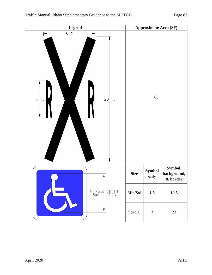
Traffic Manual: Idaho Supplementary Guidance to the MUTCD Page 83
April 2020 Part 3
Legend Approximate Area (SF)
63
Size Symbol
only
Symbol, background,
& border
Min/Std 1.5 10.5
Special 3 23

Page 84 Traffic Manual: Idaho Supplementary Guidance to the MUTCD
Part 3 April 2020
Table 3B-2. Approximate Area of Pavement Marking Letters and Numbers for 6 ft, 8 ft, and 10 ft Heights
LEGEND 6 ft 8 ft 10 ft
LEGEND 6 ft 8 ft 10 ft
LEGEND 6 ft 8 ft 10 ft
Approx. Area (SF) Approx. Area (SF) Approx. Area (SF)
A 3.0 5.5 8.3 M 4.1 7.3 11.3 Y 2.2 3.9 6.1 B 4.0 7.1 11.1 N 4.0 7.1 11.1 Z 2.9 5.1 7.9 C 2.5 4.3 6.8 O 3.2 5.6 8.7 0 3.2 5.6 8.7 D 3.4 6.0 9.3 P 3.0 5.2 8.1 1 1.5 2.6 4.1 E 3.6 6.3 9.9 Q 3.3 5.8 9.1 2 3.5 6.1 9.6 F 2.6 4.7 7.3 R 3.5 6.1 9.6 3 3.1 5.5 8.6 G 3.1 5.5 8.6 S 3.5 6.1 9.5 4 2.9 5.2 8.1 H 3.5 6.1 9.5 T 2.2 3.9 6.0 5 3.5 6.2 9.7 I 1.5 2.6 4.1 U 3.2 5.7 8.9 6 3.7 6.5 10.1 J 2.0 3.6 5.6 V 2.7 4.8 7.5 7 2.2 3.9 6.0 K 3.4 6.0 9.4 W 4.0 7.2 11.2 8 4.0 7.1 11.0 L 2.2 3.9 6.0 X 2.7 4.8 7.5 9 3.7 6.5 10.1
Section 3B.21 Speed Measurement Markings
No supplemental information.
Section 3B.22 Speed Reduction Markings
No supplemental information.
Section 3B.23 Curb Markings
Curbs or traffic separators are sometimes placed in the median of a highway. Paint the curb retroreflective solid yellow when it is less than 13.5 feet from the right edge of the adjacent lane. Use longitudinal yellow lines if the curb is 13.5 feet or more from the adjacent lane.
Section 3B.24 Chevron and Diagonal Crosshatch Markings
No supplemental information.
Section 3B.25 Speed Hump Markings
No supplemental information.
Section 3B.26 Advance Speed Hump Markings
No supplemental information.

Traffic Manual: Idaho Supplementary Guidance to the MUTCD Page 85
April 2020 Part 3
CHAPTER 3C. ROUNDABOUT MARKINGS Section 3C.01 General
Refer to “NCHRP Report 672 – Roundabouts: An Informational Guide” for additional roundabout marking guidance.
Section 3C.02 White Lane Line Pavement Markings for Roundabouts
No supplemental information.
Section 3C.03 Edge Line Pavement Markings for Roundabout Circulatory Roadways
No supplemental information.
Section 3C.04 Yield Lines for Roundabouts
No supplemental information.
Section 3C.05 Crosswalk Markings at Roundabouts
No supplemental information.
Section 3C.06 Word, Symbol, and Arrow Pavement Markings for Roundabouts
No supplemental information.
Section 3C.07 Markings for Other Circular Intersections
No supplemental information.
CHAPTER 3D. MARKINGS FOR PREFERENTIAL LANES Section 3D.01 Preferential Lane Word and Symbol Markings
No supplemental information.
Section 3D.02 Preferential Lane Longitudinal Markings for Motor Vehicles
No supplemental information.
CHAPTER 3E. MARKINGS FOR TOLL PLAZAS Section 3E.01 Markings for Toll Plazas
No supplemental information.
Page 86 Traffic Manual: Idaho Supplementary Guidance to the MUTCD
Part 3 April 2020
CHAPTER 3F. DELINEATORS Section 3F.01 Delineators
No supplemental information.
Section 3F.02 Delineator Design
ITD assigns a delineator type to single and double delineators as follows:
Type 1 – Single delineator, one direction. Type 2 – Double delineator, one direction. Type 3 – Single delineator, two directions. Type 4 – Double delineator, two directions. Type 9 – Delineator for side or top mounting on guardrail or concrete barrier.
Section 3F.03 Delineator Application
Traditionally, yellow double delineators have been used to mark the intersection of highways with other State highways or public roads. However, the use of yellow delineators adjacent to white edge lines is not permitted by the MUTCD. Intersections can be indicated with intersection warning signs (see Chapter 2C), with white delineators at intersections, or both. Delineators used to mark intersections may be enlarged to 3 x 6 inches and retroreflective.
Paragraph 06 of the MUTCD applies to median crossovers that are restricted to authorized vehicles (see Administrative Policy 5531 – Use of Median Crossovers on Interstates and Divided Highways). The paragraph does not apply to temporary median crossovers that move traffic traveling in one direction to the opposite side of a divided highway.
As described in Section 1A.08, use blue retroreflective delineators to mark median crossovers that are provided for authorized vehicles. Mark median crossovers 1,500 feet in advance of the crossover with a single (3 x 3 inch) blue delineator and 500 feet in advance of the crossover with a double (3 x 6 inch) blue delineator (see Figure 3F-1). Mark the median opening in accordance with paragraph 06 of the MUTCD with a single yellow delineator on the close side of the crossover and a double yellow delineator on the far side of the crossover. Do not install the blue devices in the same location or on the same posts as yellow delineators.
Section 3F.04 Delineator Placement and Spacing
Delineators are typically space 528 feet, or 0.1 miles apart on mainline tangent sections on Idaho Highways (see the Delineator Standard Drawing). Snow poles may be attached to delineators (see the Snow Poles Standard Drawing). A Standard Detail has been developed to show typical delineator application on interchange ramps.

Traffic Manual: Idaho Supplementary Guidance to the MUTCD Page 87
April 2020 Part 3
Figure 3F-1. Example Advance Delineation at a Median Opening

Page 88 Traffic Manual: Idaho Supplementary Guidance to the MUTCD
Part 3 April 2020
CHAPTER 3G. COLORED PAVEMENTS Section 3G.01 General
No supplemental information.
CHAPTER 3H. CHANNELIZING DEVICES USED FOR EMPHASIS OF PAVEMENT MARKING PATTERNS
Section 3H.01 Channelizing Devices
Use orange channelizing devices only in temporary traffic control zones.
CHAPTER 3I. ISLANDS Section 3I.01 General
No supplemental information.
Section 3I.02 Approach-End Treatment
No supplemental information.
Section 3I.03 Island Marking Application
No supplemental information.
Section 3I.04 Island Marking Colors
No supplemental information.
Section 3I.05 Island Delineation
No supplemental information.
Section 3I.06 Pedestrian Islands and Medians
No supplemental information.
CHAPTER 3J. RUMBLE STRIP MARKINGS Section 3J.01 Longitudinal Rumble Strip Markings
See the Rumble Strip Standard Drawings and the Roadway Design Manual.
Section 3J.02 Transverse Rumble Strip Markings
No supplemental information.

Traffic Manual: Idaho Supplementary Guidance to the MUTCD Page 89
April 2020 Part 3
CHAPTER 3K. HIGHWAY MEMORIAL MARKERS AND OTHER MARKERS (Chapter is not in the MUTCD)
Section 3K.01 Traffic Accident Memorials (Section is not in the MUTCD)
Idaho Statute 49-1316 allows relatives or friends of a person killed in a crash to erect a “traffic accident memorial” in memory of the deceased. IDAPA 39.03.63 “Rules Governing Traffic Accident Memorials,” addresses the permitting and the dimensions and material, location, and maintenance of the memorial.
Section 3K.02 Blue Star Memorial Markers (Section is not in the MUTCD)
The National Garden Club provides tribute to the Armed Forces of America with Blue Star memorial highway and by-way markers. Treat Garden Club requests to construct Blue Star memorial markers similarly to those for “traffic accident memorials” and with engineering judgment.
Section 3K.03 Private Approach Markers (Section is not in the MUTCD)
Private approaches are not normally marked. Agencies responsible for emergency response may mark the address of rural properties with a 6 x 18 inch blue marker. The marker may be retroreflective. If used, the blue markers are the responsibility of the emergency response agency or of the property owner.
Page 90 Traffic Manual: Idaho Supplementary Guidance to the MUTCD
Part 3 April 2020
This Page Intentionally Left Blank

Traffic Manual: Idaho Supplementary Guidance to the MUTCD Page 91
April 2020 Part 4
CHAPTER 4A. GENERAL Section 4A.01 Types
No supplemental information.
Section 4A.02 Definitions Relating to Highway Traffic Signals
No supplemental information.
CHAPTER 4B. TRAFFIC CONTROL SIGNALS - GENERAL Section 4B.01 General
Administrative Policy 5016 – Traffic Regulation – outlines the Department’s distribution of responsibilities such as Traffic Minute Entry approval authority and State and local agreement costs for traffic control devices.
Section 4B.02 Basis of Installation or Removal of Traffic Control Signals
A request for a new traffic signal or improvement to an existing traffic signal is generally initiated from the police, a public official, or within the Department. The request and proposed intersection improvement should be reviewed with the District Traffic Engineer prior to any commitment of ITD to a traffic signal installation.
Section 4B.03 Advantages and Disadvantages of Traffic Control Signal
No supplemental information.
Section 4B.04 Alternatives to Traffic Control Signals
No supplemental information.
Section 4B.05 Adequate Roadway Capacity
No supplemental information.
PART 4 HIGHWAY TRAFFIC SIGNALS

Page 92 Traffic Manual: Idaho Supplementary Guidance to the MUTCD
Part 4 April 2020
CHAPTER 4C. TRAFFIC CONTROL SIGNAL NEEDS STUDIES Section 4C.01 Studies and Factors for Justifying Traffic Control Signals
No supplemental information.
Section 4C.02 Warrant 1, Eight-Hour Vehicular Volume
No supplemental information.
Section 4C.03 Warrant 2, Four-Hour Vehicular Volume
No supplemental information.
Section 4C.04 Warrant 3, Peak Hour
No supplemental information.
Section 4C.05 Warrant 4, Pedestrian Volume
No supplemental information.
Section 4C.06 Warrant 5, School Crossing
No supplemental information.
Section 4C.07 Warrant 6, Coordinated Signal System
No supplemental information.
Section 4C.08 Warrant 7, Crash Experience
No supplemental information.
Section 4C.09 Warrant 8, Roadway Network
No supplemental information.
Section 4C.10 Warrant 9, Intersection Near a Grade Crossing
No supplemental information.

Traffic Manual: Idaho Supplementary Guidance to the MUTCD Page 93
April 2020 Part 4
CHAPTER 4D. TRAFFIC CONTROL SIGNAL FEATURES Section 4D.01 General
Refer to “NCHRP Report 812 – Signal Timing Manual” for guidance on clearance intervals, traffic control signal timing, and corridor coordination. Resources such as FHWA’s “Signalized Intersections Informational Guide” and “Traffic Detector Handbook,” ITE’s “Traffic Control Devices Handbook,” and others contain design information that is not included in the MUTCD. “NCHRP Report 500, Volume 12 – A Guide for Reducing Collisions at Signalized Intersections” and the crash modification factors (CMF) clearinghouse may be used to reduce the number of collisions at signalized intersections.
Section 4D.02 Responsibility for Operation and Maintenance
A traffic signal agreement should be in place for all traffic signal installations on the State highway system. Refer to Administrative Policy 5016 – Traffic Regulation for guidance on what the agreement should contain.
The timing of each signal controller should be reviewed and updated as needed (construction or special event impacts) or least once a year.
Section 4D.03 Provisions for Pedestrians
Pedestrian signals should be considered for signalized intersection crossings that have curb and sidewalk unless pedestrians are not permitted because of geometric constraints or if No Pedestrian Crossing (R9-3) signs are installed. Pedestrian signals should be considered at rural intersections unless there is little potential for pedestrian traffic. Refer to the Bicycle/Pedestrian Facilities Administrative Policy when deciding not to install pedestrian signals.
Section 4D.04 Meaning of Vehicular Signal Indications
Idaho Statute 49-802 – Traffic-Control Signal Legend – describes similar meanings as Section 4D.04, but with some minor differences. Idaho Statute 49-804 – Flashing Signals – describes the meanings of flashing signals.
Idaho Statute 49-802(3)(a) and IDAPA Rule 39.03.41 – Rules Governing Traffic Control Devices – allow vehicles facing a steady CIRCULAR RED signal indication to turn left from a two-way highway onto a one-way street after stopping and yielding to other users.
Idaho Statute 49-802(3)(e) allows the driver of a motorcycle to proceed through a traffic control signal after exercising due caution and care when facing a CIRCULAR RED or RED ARROW if after one signal cycle the detection equipment does not detect the motorcycle.
See Idaho Statute 49-804 –Flashing Signals – for the meaning of flashing signal indications.
Idaho Statute 49-720 allows a bicyclist facing a steady CIRCULAR RED or RED ARROW signal indication to stop, yield to other traffic, and proceed through the traffic control signal as if it were a STOP controlled intersection (see Section 9D.02).
Section 4D.05 Application of Steady Signal Indications
No supplemental information.

Page 94 Traffic Manual: Idaho Supplementary Guidance to the MUTCD
Part 4 April 2020
Section 4D.06 Signal Indications - Design, Illumination, Color, and Shape
No supplemental information.
Section 4D.07 Size of Vehicular Signal Indications
No supplemental information.
Section 4D.08 Positions of Signal Indications Within a Signal Face - General
Horizontally-arranged signal faces are not typically used in Idaho, but are shown in the Idaho Driver’s Manual and may be used based on engineering judgment.
Section 4D.09 Positions of Signal Indications Within a Vertical Signal Face
No supplemental information.
Section 4D.10 Positions of Signal Indications Within a Horizontal Signal Face
No supplemental information.
Section 4D.11 Number of Signal Faces on an Approach
On approaches with two or more lanes for the through movement, provide one signal face per through lane, centered over the through lane, unless otherwise determined through engineering judgment.
Section 4D.12 Visibility, Aiming, and Shielding of Signal Faces
In accordance with Idaho Statute 49-805 – Display of Unauthorized Signs, Signals, or Markings – an object that hides from view or interferes with the effectiveness of a traffic control device (including a traffic control signal) is prohibited and can be removed.
A Signal Ahead (W3-3) sign and Warning Beacon installed to warn approaching road users of the traffic control signal is referred to as Dynamic Signal Warning Flashers in the CMF Clearinghouse.
Section 4D.13 Lateral Positioning of Signal Faces
Left-turn primary signal faces can be offset to the right of the center of the left-turning lane to ensure that the signal face is not blocked by the opposing signal face if engineering judgment determines that doing so will improve traffic control signal operations. If offset, position the primary left-turn signal face four feet from the right edge of the turn lane.
Section 4D.14 Longitudinal Positioning of Signal Faces
No supplemental information.
Section 4D.15 Mounting Height of Signal Faces
No supplemental information.
Section 4D.16 Lateral Offset (Clearance) of Signal Faces
No supplemental information.

Traffic Manual: Idaho Supplementary Guidance to the MUTCD Page 95
April 2020 Part 4
Section 4D.17 Signal Indications for Left-Turn Movements - General
Use Figure 4D-1 to evaluate left-turn phasing. When implementing permitted left-turn phasing in conjunction with the pedestrian phase of the same movement, consider the use of a leading pedestrian interval in MUTCD Section 4E.06 or inhibit the permitted left-turn phase during such time. If crash and volume data indicate a particular left-turn phase for a certain time of day, consider using such left-turn phasing only during that time.
Section 4D.18 Signal Indications for Permissive Only Mode Left-Turn Movements
No supplemental information.
Section 4D.19 Signal Indications for Protected Only Mode Left-Turn Movements
No supplemental information.
Section 4D.20 Signal Indications for Protected/Permissive Mode Left-Turn Movements
No supplemental information.
Section 4D.21 Signal Indications for Right-Turn Movements - General
No supplemental information.
Section 4D.22 Signal Indications for Permissive Only Mode Right-Turn Movements
No supplemental information.
Section 4D.23 Signal Indications for Protected Only Mode Right-Turn Movements
No supplemental information.
Section 4D.24 Signal Indications for Protected/Permissive Mode Right-Turn Movements
No supplemental information.
Section 4D.25 Signal Indications for Approaches With Shared Left-Turn/Right-Turn Lanes and No Through Movement
No supplemental information.
Section 4D.26 Yellow Change and Red Clearance Intervals
Refer to “NCHRP Report 812 Signal Timing Manual” for Yellow Change and Red Clearance calculations.

Page 96 Traffic Manual: Idaho Supplementary Guidance to the MUTCD
Part 4 April 2020
Figure 4D-1 Left-Turn Phasing Guide (Sheet 1 of 2)
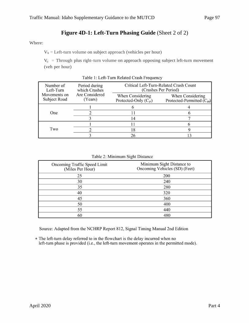
Traffic Manual: Idaho Supplementary Guidance to the MUTCD Page 97
April 2020 Part 4
Figure 4D-1: Left-Turn Phasing Guide (Sheet 2 of 2)
Where:
Vlt = Left-turn volume on subject approach (vehicles per hour)
V0 = Through plus right- turn volume on approach opposing subject left-turn movement (veh per hour)

Page 98 Traffic Manual: Idaho Supplementary Guidance to the MUTCD
Part 4 April 2020
Section 4D.27 Preemption and Priority Control of Traffic Control Signals
During a preemption call ITD signal controllers are typically programmed to first cancel phases displaying a flashing yellow arrow indication and then to provide green indications to all phases in the preempted direction.
ITD will normally only install emergency vehicle preemption equipment at the request of a local agency after an agreement with that agency has been established. The following are examples of items that should be addressed in the agreement. ITD generally will:
• Approve preemption signal phasing. • Approve and modify controller equipment within the traffic signal controller cabinet
to accommodate preemption by approach.
The local agency generally will:
• Furnish and maintain the equipment that is to be installed by the local agency within the pre-wired controller cabinet under the supervision of ITD.
• Furnish, install, and maintain the equipment from the emergency vehicle station to the controller cabinet.
• Furnish, install, and maintain the equipment to provide an indication to the driver of an emergency vehicle that the controller has been successfully preempted.
Section 4D.28 Flashing Operation of Traffic Control Signals - General
No supplemental information.
Section 4D.29 Flashing Operation –Transition Into Flashing Mode
No supplemental information.
Section 4D.30 Flashing Operation – Signal Indications During Flashing Mode
No supplemental information.
Section 4D.31 Flashing Operation –Transition Out of Flashing Mode
No supplemental information.
Section 4D.32 Temporary and Portable Traffic Control Signals
No supplemental information.
Section 4D.33 Lateral Offset of Signal Supports and Cabinets
No supplemental information.
Section 4D.34 Use of Signs at Signalized Locations
No supplemental information.
Section 4D.35 Use of Pavement Markings at Signalized Locations
No supplemental information.

Traffic Manual: Idaho Supplementary Guidance to the MUTCD Page 99
April 2020 Part 4
CHAPTER 4E. PEDESTRAIN CONTROL FEATURES Section 4E.01 Pedestrian Signal Heads
No supplemental information.
Section 4E.02 Meaning of Pedestrian Signal Head Indications
See Idaho Statute 49-803 – Pedestrian-Control Signals – for the statutory definition of pedestrian signal head indications. The definitions are obsolete and ITD installs pedestrian signal heads as described in the MUTCD.
Section 4E.03 Application of Pedestrian Signal Heads
No supplemental information.
Section 4E.04 Size, Design, and Illumination of Pedestrian Signal Head Indications
No supplemental information.
Section 4E.05 Location and Height of Pedestrian Signal Heads
No supplemental information.
Section 4E.06 Pedestrian Intervals and Signal Phases
No supplemental information.
Section 4E.07 Countdown Pedestrian Signals
No supplemental information.
Section 4E.08 Pedestrian Detectors
ITD Standard Drawings provide additional pedestrian pushbutton location and curb ramp information.
Section 4E.09 Accessible Pedestrian Signals and Detectors - General
Accessible pedestrian signals (APS) are not installed by ITD unless requested by an individual that may benefit from information provided in a non-visual format, justified by an engineering study, and reviewed and approved by an ITD multi-disciplinary team. Requests by agencies, advocates, or others are not considered.
When an APS request is received, a review committee consisting of the applicable District Traffic Engineer, a staff member from the Office of Civil Rights, and a staff member from the Headquarters Design/Traffic Services section will be convened. The District Traffic Engineer will conduct an engineering study in accordance with the MUTCD and 23 USC 217(g) and will retain study documentation.
Section 4E.10 Accessible Pedestrian Signals and Detectors - Location
No supplemental information.
Section 4E.11 Accessible Pedestrian Signals and Detectors – Walk Indications
No supplemental information.

Page 100 Traffic Manual: Idaho Supplementary Guidance to the MUTCD
Part 4 April 2020
Section 4E.12 Accessible Pedestrian Signals and Detectors – Tactile Arrows and Locator Tones
No supplemental information.
Section 4E.13 Accessible Pedestrian Signals and Detectors – Extended Pushbutton Press Features
No supplemental information.
CHAPTER 4F. PEDESTRAIN HYBRID BEACONS Section 4F.01 Application of Pedestrian Hybrid Beacons
No supplemental information.
Section 4F.02 Design of Pedestrian Hybrid Beacons
No supplemental information.
Section 4F.03 Operation of Pedestrian Hybrid Beacons
No supplemental information.
CHAPTER 4G. TRAFFIC CONTROL SIGNALS AND HYBRID BEACONS FOR EMERGENCY-VEHICLE ACCESS
Section 4G.01 Application of Emergency-Vehicle Traffic Control Signals and Hybrid Beacons
No supplemental information.
Section 4G.02 Design of Emergency-Vehicle Traffic Control Signals
No supplemental information.
Section 4G.03 Operation of Emergency-Vehicle Traffic Control Signals
No supplemental information.
Section 4G.04 Emergency-Vehicle Hybrid Beacons
No supplemental information.
CHAPTER 4H. TRAFFIC CONTROL SIGNALS FOR ONE-LANE, TWO-WAY FACILITIES
Section 4H.01 Application of Traffic Control Signals for One-Lane, Two-Way Facilities
No supplemental information.
Traffic Manual: Idaho Supplementary Guidance to the MUTCD Page 101
April 2020 Part 4
Section 4H.02 Design of Traffic Control Signals for One-Lane, Two-way Facilities
No supplemental information.
Section 4H.03 Operation of Traffic Control Signals for One-Lane, Two-Way Facilities
No supplemental information.
CHAPTER 4I. TRAFFIC CONTROL SIGNALS FOR FREEWAY ENTRANCE RAMPS
Section 4I.01 Application of Freeway Entrance Ramp Control Signals
No supplemental information.
Section 4I.02 Design of Freeway Entrance Ramp Control Signals
No supplemental information.
Section 4I.03 Operation of Freeway Entrance Ramp Control Signals
No supplemental information.
CHAPTER 4J. TRAFFIC CONTROL FOR MOVABLE BRIDGES Section 4J.01 Application of Traffic Control for Movable Bridges
No supplemental information.
Section 4J.02 Design and Location of Movable Bridge Signals and Gates
No supplemental information.
Section 4J.03 Operation of Movable Bridge Signals and Gates
No supplemental information.
CHAPTER 4K. HIGHWAY TRAFFIC SIGNALS AT TOLL PLAZAS Section 4K.01 Traffic Signals at Toll Plazas
No supplemental information.
Section 4K.02 Lane-Use Control Signals at or Near Toll Plazas
No supplemental information.
Section 4K.03 Warning Beacons at Toll Plazas
No supplemental information.

Page 102 Traffic Manual: Idaho Supplementary Guidance to the MUTCD
Part 4 April 2020
CHAPTER 4L. FLASHING BEACONS Section 4L.01 General Design and Operation of Flashing Beacons
See Idaho Statute 49-804 –Flashing Signals – for the definition of flashing (signals) Beacons.
Section 4L.02 Intersection Control Beacon
See Idaho Statute 49-804 –Flashing Signals – for the meaning of flashing beacon (signal) indications.
Section 4L.03 Warning Beacon
In accordance with IDAPA Rule 39.03.41 –Rules Governing Traffic Control Devices – beacons cannot be included within the border of a sign.
Rectangular Rapid-Flashing Beacons (RRFB) may be used as a pedestrian-actuated conspicuity enhancement for pedestrian and school crossing warning signs. ITD has received interim approval from FHWA to use RRFBs. Local agencies must request interim approval from FHWA to use RRFBs on roadways within their jurisdictions.
Figure 4L-1 Rectangular Rapid Flashing Beacon
The following conditions apply to the use of the RRFB:
1. General Conditions: a. Each RRFB unit shall consist of two rapidly flashed rectangular-shaped yellow
indications with an LED-array-based light source, and shall be designed, located, and operated in accordance with the detailed requirements specified below.
b. The use of RRFBs is optional. However, if RRFBs are used, the following design and operational requirements shall apply, and shall take precedence over any conflicting provisions of the MUTCD for the approach on which RRFBs are used:
2. Allowable Uses: a. An RRFB shall only be installed to function as a pedestrian-actuated conspicuity
enhancement.
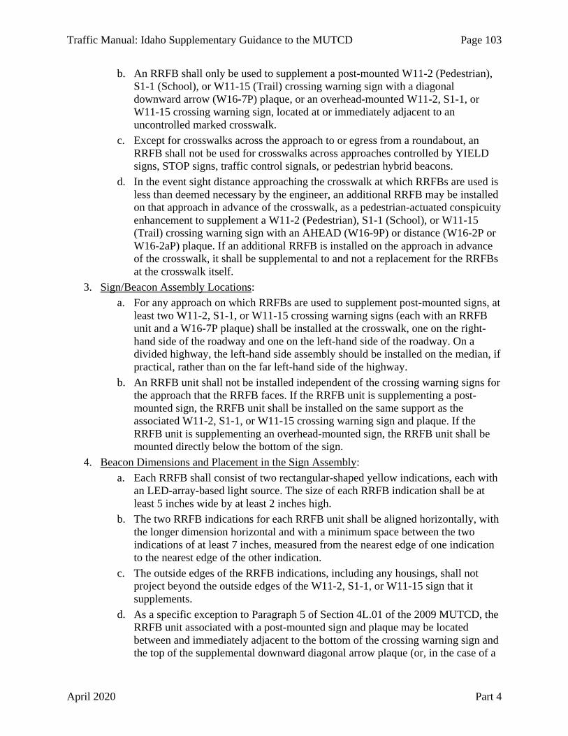
Traffic Manual: Idaho Supplementary Guidance to the MUTCD Page 103
April 2020 Part 4
b. An RRFB shall only be used to supplement a post-mounted W11-2 (Pedestrian), S1-1 (School), or W11-15 (Trail) crossing warning sign with a diagonal downward arrow (W16-7P) plaque, or an overhead-mounted W11-2, S1-1, or W11-15 crossing warning sign, located at or immediately adjacent to an uncontrolled marked crosswalk.
c. Except for crosswalks across the approach to or egress from a roundabout, an RRFB shall not be used for crosswalks across approaches controlled by YIELD signs, STOP signs, traffic control signals, or pedestrian hybrid beacons.
d. In the event sight distance approaching the crosswalk at which RRFBs are used is less than deemed necessary by the engineer, an additional RRFB may be installed on that approach in advance of the crosswalk, as a pedestrian-actuated conspicuity enhancement to supplement a W11-2 (Pedestrian), S1-1 (School), or W11-15 (Trail) crossing warning sign with an AHEAD (W16-9P) or distance (W16-2P or W16-2aP) plaque. If an additional RRFB is installed on the approach in advance of the crosswalk, it shall be supplemental to and not a replacement for the RRFBs at the crosswalk itself.
3. Sign/Beacon Assembly Locations: a. For any approach on which RRFBs are used to supplement post-mounted signs, at
least two W11-2, S1-1, or W11-15 crossing warning signs (each with an RRFB unit and a W16-7P plaque) shall be installed at the crosswalk, one on the right-hand side of the roadway and one on the left-hand side of the roadway. On a divided highway, the left-hand side assembly should be installed on the median, if practical, rather than on the far left-hand side of the highway.
b. An RRFB unit shall not be installed independent of the crossing warning signs for the approach that the RRFB faces. If the RRFB unit is supplementing a post-mounted sign, the RRFB unit shall be installed on the same support as the associated W11-2, S1-1, or W11-15 crossing warning sign and plaque. If the RRFB unit is supplementing an overhead-mounted sign, the RRFB unit shall be mounted directly below the bottom of the sign.
4. Beacon Dimensions and Placement in the Sign Assembly: a. Each RRFB shall consist of two rectangular-shaped yellow indications, each with
an LED-array-based light source. The size of each RRFB indication shall be at least 5 inches wide by at least 2 inches high.
b. The two RRFB indications for each RRFB unit shall be aligned horizontally, with the longer dimension horizontal and with a minimum space between the two indications of at least 7 inches, measured from the nearest edge of one indication to the nearest edge of the other indication.
c. The outside edges of the RRFB indications, including any housings, shall not project beyond the outside edges of the W11-2, S1-1, or W11-15 sign that it supplements.
d. As a specific exception to Paragraph 5 of Section 4L.01 of the 2009 MUTCD, the RRFB unit associated with a post-mounted sign and plaque may be located between and immediately adjacent to the bottom of the crossing warning sign and the top of the supplemental downward diagonal arrow plaque (or, in the case of a

Page 104 Traffic Manual: Idaho Supplementary Guidance to the MUTCD
Part 4 April 2020
supplemental advance sign, the AHEAD or distance plaque) or within 12 inches above the crossing warning sign, rather than the recommended minimum of 12 inches above or below the sign assembly. (See the example photo that is shown below.)
5. Beacon Flashing Requirements: a. When actuated, the two yellow indications in each RRFB unit shall flash in a
rapidly flashing sequence. b. As a specific exception to the requirements for the flash rate of beacons provided
in Paragraph 3 of Section 4L.01, RRFBs shall use a much faster flash rate and shall provide 75 flashing sequences per minute. Except as provided in Condition 5f below, during each 800-millisecond flashing sequence, the left and right RRFB indications shall operate using the following sequence:
The RRFB indication on the left-hand side shall be illuminated for approximately 50 milliseconds. Both RRFB indications shall be dark for approximately 50 milliseconds.
The RRFB indication on the right-hand side shall be illuminated for approximately 50 milliseconds. Both RRFB indications shall be dark for approximately 50 milliseconds.
Both RRFB indications shall be illuminated for approximately 50 milliseconds. Both RRFB indications shall be dark for approximately 50 milliseconds.
Both RRFB indications shall be illuminated for approximately 50 milliseconds. Both RRFB indications shall be dark for approximately 250 milliseconds.
c. The flash rate of each individual RRFB indication, as applied over the full flashing sequence, shall not be between 5 and 30 flashes per second to avoid frequencies that might cause seizures.
d. The light intensity of the yellow indications during daytime conditions shall meet the minimum specifications for Class 1 yellow peak luminous intensity in the Society of Automotive Engineers (SAE) Standard J595 (Directional Flashing Optical Warning Devices for Authorized Emergency, Maintenance, and Service Vehicles) dated January 2005.

Traffic Manual: Idaho Supplementary Guidance to the MUTCD Page 105
April 2020 Part 4
e. To minimize excessive glare during nighttime conditions, an automatic signal dimming device should be used to reduce the brilliance of the RRFB indications during nighttime conditions.
f. Existing RRFB units that use the flashing sequence that was specified in the Interim Approval 11 memorandum and a subsequent interpretation (the RRFB indication on the left-hand side emits two slow pulses of light after which the RRFB indication on the right-hand side emits four rapid pulses of light followed by one long pulse of light) should be reprogrammed to the flash pattern specified above in Condition 5b as part of a systematic upgrading process, such as when the units are serviced or when the existing signs are replaced.
6. Beacon Operation: a. The RRFB shall be normally dark, shall initiate operation only upon pedestrian
actuation, and shall cease operation at a predetermined time after the pedestrian actuation or, with passive detection, after the pedestrian clears the crosswalk.
b. All RRFB units associated with a given crosswalk (including those with an advance crossing sign, if used) shall, when actuated, simultaneously commence operation of their rapid-flashing indications and shall cease operation simultaneously.
c. If pedestrian pushbutton detectors (rather than passive detection) are used to actuate the RRFB indications, a Push Button To Turn On Warning Lights (R10-25) sign (see MUTCD Figure 2B-26) shall be installed explaining the purpose and use of the pedestrian pushbutton detector.
d. The duration of a predetermined period of operation of the RRFBs following each actuation should be based on the procedures provided in Section 4E.06 of the 2009 MUTCD for the timing of pedestrian clearance times for pedestrian signals.
e. The predetermined flash period shall be immediately initiated each and every time that a pedestrian is detected either through passive detection or as a result of a pedestrian pressing a pushbutton detector, including when pedestrians are detected while the RRFBs are already flashing and when pedestrians are detected immediately after the RRFBs have ceased flashing.
f. A small pilot light may be installed integral to the RRFB or pedestrian pushbutton detector to give confirmation that the RRFB is in operation.
7. Accessible Pedestrian Features: a. If a speech pushbutton information message is used in conjunction with an RRFB,
a locator tone shall be provided. b. If a speech pushbutton information message is used in conjunction with an RRFB,
the audible information device shall not use vibrotactile indications or percussive indications.
c. If a speech pushbutton information message is used in conjunction with an RRFB, the message should say, "Yellow lights are flashing." The message should be spoken twice.
Section 4L.04 Speed Limit Sign Beacon
No supplemental information.

Page 106 Traffic Manual: Idaho Supplementary Guidance to the MUTCD
Part 4 April 2020
Section 4L.05 Stop Beacon
No supplemental information.
CHAPTER 4M. LANE-USE CONTROL SIGNALS Section 4M.01 Application of Lane-Use Control Signals
No supplemental information.
Section 4M.02 Meaning of Lane-Use Control Signal Indications
Refer to Idaho Statute 49-806 –Lane Use Control Signals – when considering the use of Lane Use Control Signals.
Section 4M.03 Design of Lane-Use Control Signals
No supplemental information.
Section 4M.04 Operation of Lane-Use Control Signals
No supplemental information.
CHAPTER 4N. IN –ROADWAY LIGHTS Section 4N.01 Application of In-Roadway Lights
No supplemental information.
Section 4N.02 In-Roadway Warning Lights at Crosswalks
No supplemental information.

Traffic Manual: Idaho Supplementary Guidance to the MUTCD Page 107
April 2020 Part 5
CHAPTER 5A. GENERAL Section 5A.01 Function
State highways, regardless of traffic volumes, use typical traffic control devices. Traffic control devices for low-volume roads may be used only on applicable local rural road systems.
Section 5A.02 Application
No Supplemental Information.
Section 5A.03 Design
No Supplemental Information.
Section 5A.04 Placement
No Supplemental Information.
CHAPTER 5B. REGULATORY SIGNS Section 5B.01 Introduction
No Supplemental Information.
Section 5B.02 STOP and YIELD Signs (R1-1 and R1-2)
No Supplemental Information.
Section 5B.03 Speed Limit Signs (R2 Series)
No Supplemental Information.
Section 5B.04 Traffic Movement and Prohibition Signs (R3, R4, R5, R6, R9, R10, R11, R12, R13, and R14 Series)
No Supplemental Information.
Section 5B.05 Parking Signs (R8 Series)
No Supplemental Information.
Section 5B.06 Other Regulatory Signs
No Supplemental Information.
PART 5 TRAFFIC CONTROL DEVICES FOR LOW-VOLUME ROADS

Page 108 Traffic Manual: Idaho Supplementary Guidance to the MUTCD
Part 5 April 2020
CHAPTER 5C. WARNING SIGNS Section 5C.01 Introduction
No Supplemental Information.
Section 5C.02 Horizontal Alignment Signs (W1-1 through W1-8)
No Supplemental Information.
Section 5C.03 Intersection Warning Signs (W2-1 through W2-6)
No Supplemental Information.
Section 5C.04 Stop Ahead and Yield Ahead Signs (W3-1, W3-2)
No Supplemental Information.
Section 5C.05 NARROW BRIDGE Sign (W5-2)
No Supplemental Information.
Section 5C.06 ONE LANE BRIDGE Sign (W5-3)
No Supplemental Information.
Section 5C.07 Hill Sign (W7-1)
No Supplemental Information.
Section 5C.08 PAVEMENT ENDS Sign (W8-3)
No Supplemental Information.
Section 5C.09 Vehicular Traffic Warning and Non-Vehicular Warning Signs (W11 Series and W86)
No Supplemental Information.
Section 5C.10 Advisory Speed Plaque (W13-1P)
No Supplemental Information.
Section 5C.11 DEAD END or NO OUTLET Signs (W14-1, W14-1a, W14-2, W14-2a)
No Supplemental Information.
Section 5C.12 NO TRAFFIC SIGNS Sign (W18-1)
No Supplemental Information.
Section 5C.13 Other Warning Signs
No Supplemental Information.
Section 5C.14 Object Markers and Barricades
No Supplemental Information.
Traffic Manual: Idaho Supplementary Guidance to the MUTCD Page 109
April 2020 Part 5
CHAPTER 5D. GUIDE SIGNS Section 5D.01 Introduction
No Supplemental Information.
CHAPTER 5E. MARKINGS Section 5E.01 Introduction
No Supplemental Information.
Section 5E.02 Center Line Markings
No Supplemental Information.
Section 5E.03 Edge Line Markings
No Supplemental Information.
Section 5E.04 Delineators
No Supplemental Information.
Section 5E.05 Other Markings
No Supplemental Information.
CHAPTER 5F. TRAFFIC CONTROL FOR HIGHWAY-RAIL GRADE CROSSINGS
Section 5F.01 Introduction
No Supplemental Information.
Section 5F.02 Grade Crossing (Crossbuck) Sign and Number of Tracks Plaque (R15-1, R15-2P)
No Supplemental Information.
Section 5F.03 Grade Crossing Advance Warning Signs (W10 Series)
No Supplemental Information.
Section 5F.04 STOP AND YIELD Signs (R1-1, R1-2)
No Supplemental Information.
Section 5F.05 Pavement Markings
No Supplemental Information.
Section 5F.06 Other Traffic Control Devices
No Supplemental Information.

Page 110 Traffic Manual: Idaho Supplementary Guidance to the MUTCD
Part 5 April 2020
CHAPTER 5G. TEMPORARY TRAFFIC CONTROL ZONES Section 5G.01 Introduction
No Supplemental Information.
Section 5G.02 Applications
No Supplemental Information.
Section 5G.03 Channelization Devices
No Supplemental Information.
Section 5G.04 Markings
No Supplemental Information.
Section 5G.05 Other Traffic Control Devices
No Supplemental Information.
CHAPTER 5H. TRAFFIC CONTROL FOR SCHOOL AREAS Section 5H.01 Introduction
No Supplemental Information.

Traffic Manual: Idaho Supplementary Guidance to the MUTCD Page 111
April 2020 Part 6
CHAPTER 6A. GENERAL Section 6A.01 General
Use the “Work Zone Safety and Mobility (WZSM) Program” on highway projects. The WZSM program provides guidance associated with federal regulations 23 CFR 630 Subpart J – Work Zone Safety and Mobility, and Subpart K – Temporary Traffic Control Devices. Also refer to the ITD “Operations Manual.”
CHAPTER 6B. FUNDAMENTAL PRINCIPLES Section 6B.01 Fundamental Principles of Temporary Traffic Control
Maintenance of traffic and maintenance of temporary detours are addressed in Section 105 of ITD’s “Standard Specifications for Highway Construction.”
CHAPTER 6C. TEMPORARY TRAFFIC CONTROL ELEMENTS Section 6C.01 Temporary Traffic Control Plans
Training requirements for personnel involved in the development, design, implementation, operation, inspection, and enforcement of TTC plans on Federal-aid highway projects are listed in the “Work Zone Safety and Mobility Program.”
Indicate the background color of warning signs on the TTC plan.
Section 6C.02 Temporary Traffic Control Zones
See Administrative Policy 5546 – Special Events on State Highways – for information about Special Event requirements, applications, agreements, and fees.
Section 6C.03 Components of Temporary Traffic Control Zones
No supplemental information.
Section 6C.04 Advance Warning Area
For MUTCD Table 6C-1, use the following speeds for low and high speed urban road types, unless otherwise determined by engineering judgment:
Section 6C.05 Transition Area
No supplemental information.
Urban (Low Speed): 35 mph or lower Urban (High Speed): 40 mph or greater
PART 6 TEMPORARY TRAFFIC CONTROL

Page 112 Traffic Manual: Idaho Supplementary Guidance to the MUTCD
Part 6 April 2020
Section 6C.06 Activity Area
No supplemental information.
Section 6C.07 Termination Area
No supplemental information.
Section 6C.08 Tapers
No supplemental information.
Section 6C.09 Detours and Diversions
Coordinate detours that route traffic off of the highway system with the local highway agency. Consider initiating a cooperative agreement between ITD and the local highway agency if the traffic is being detoured for long periods of time or if the detoured traffic is anticipated to cause damage to the local highway system.
Section 6C.10 One-Lane, Two-Way Traffic Control
No supplemental information.
Section 6C.11 Flagger Method of One-Lane, Two-Way Traffic Control
No supplemental information.
Section 6C.12 Flag Transfer Method of One-Lane, Two-Way Traffic Control
No supplemental information.
Section 6C.13 Pilot Car Method of One-Lane, Two-Way Traffic Control
No supplemental information.
Section 6C.14 Temporary Traffic Control Signal Method of One-Lane, Two-Way Traffic Control
No supplemental information.
Section 6C.15 Stop or Yield Control Method of One-Lane, Two-Way Traffic Control
No supplemental information.

Traffic Manual: Idaho Supplementary Guidance to the MUTCD Page 113
April 2020 Part 6
CHAPTER 6D. PEDESTRIAN AND WORKER SAFETY Section 6D.01 Pedestrian Considerations
Refer to the “Work Zone Safety and Mobility Program” for an ITD policy statement regarding pedestrians and other road users within work zones.
Section 6D.02 Accessibility Considerations
No supplemental information.
Section 6D.03 Worker Safety Considerations
Use the “Work Zone Positive Protection Guidance” workbook (ITD Form 0283) to determine where and when to use positive protection, such as temporary traffic barriers. Refer to the “Work Zone Safety and Mobility Program.”
Training requirements for personnel involved in the development, design, implementation, operation, inspection, and enforcement of TTC plans on Federal-aid highway projects are listed in the “Work Zone Safety and Mobility Program.”
CHAPTER 6E. FLAGGER CONTROL Section 6E.01 Qualifications for Flaggers
Flaggers must be trained and possess a current flagger certification from ATSSA or the Evergreen Safety Council or possess a current flagger certification that was obtained in Washington, Oregon, Montana, or Utah. ITD has reciprocity agreements to recognize certifications obtained in those states. Refer to the “Work Zone Safety and Mobility Program.”
Section 6E.02 High-Visibility Safety Apparel
No supplemental information.
Section 6E.03 Hand-Signaling Devices
No supplemental information.
Section 6E.04 Automated Flagger Assistance Devices
ITD’s policy governing AFAD application is that AFADs can be used if an engineering study estimates that AFAD use will improve temporary traffic control zone safety or reduce project cost without detrimentally affecting temporary traffic control zone safety. Consider the following in the engineering study:
A. Conditions applicable for the use of Method 1 and Method 2 AFAD operation,
B. Highway volume,
C. Maximum distance between AFADs,
D. Conflicting lenses/indications monitoring,
E. Fail safe procedures,
F. Need for additional signing and pavement markings,

Page 114 Traffic Manual: Idaho Supplementary Guidance to the MUTCD
Part 6 April 2020
G. Application consistency,
H. Use of larger signs or lenses to increase visibility,
I. Use of backplates.
Section 6E.05 STOP/SLOW Automated Flagger Assistance Devices
No supplemental information.
Section 6E.06 Red/Yellow Lens Automated Flagger Assistance Devices
No supplemental information.
Section 6E.07 Flagger Procedures
No supplemental information.
Section 6E.08 Flagger Stations
No supplemental information.
CHAPTER 6F. TEMORARY TRAFFIC CONTROL ZONE DEVICES Section 6F.01 Types of Devices
Temporary traffic control devices are specified in Section 626 of the ITD “Standard Specifications for Highway Construction.” Maintain temporary traffic control devices to the acceptable or marginal levels described in the ATSSA “Quality Guidelines for Temporary Traffic Control Devices and Features.”
Section 6F.02 General Characteristics of Signs
Indicate the background color of warning signs on the TTC plan. For example, if the SOFT SHOULDER (W8-4) sign is used, indicate the sign number and color as W8-4(O).
Warning signs and plaques larger than those shown in MUTCD Table 6F-1 are encouraged.
The ROAD WORK NEXT XX MILES (G20-1) sign size may be increased to 60 x 24 inches.
The END ROAD WORK (G20-2) sign size may be increased to 48 x 24 inches for conventional roads.
Section 6F.03 Sign Placement
Ensure that sign placement does not inhibit intersection sight triangles as defined in AASHTO’s “A Policy on Geometric Design of Highways and Streets.”
Section 6F.04 Sign Maintenance
No supplemental information.
Section 6F.05 Regulatory Sign Authority
No supplemental information.
Section 6F.06 Regulatory Sign Design
No supplemental information.

Traffic Manual: Idaho Supplementary Guidance to the MUTCD Page 115
April 2020 Part 6
Section 6F.07 Regulatory Sign Applications
No supplemental information.
Section 6F.08 ROAD (STREET) CLOSED Sign (R11-2)
No supplemental information.
Section 6F.09 Local Traffic Only Signs (R11-3a, R11-4)
No supplemental information.
Section 6F.10 Weight Limit Signs (R12-1, R12-2, R12-5)
Idaho Statute 49-1005 – Special Regulations and Notice – gives ITD authority to reduce the permissible size, weight, or speeds of vehicles operating on a highway for a period of time for the protection of the highway or for public safety due to climatic or other reasons. IDAPA 39.03.14 – Rules Governing Policy During Spring Breakup Season – provides additional information about the application of the statute.
Use Weight Limit signs (R12 Series) when vehicle weight loadings are restricted to a maximum weight or maximum weight per axle (see Section 2B.59). Use the BEGIN (R3-9cP) and END (R3-9dP) plaques to inform road users where the weight limit begins and ends (see Section 2B.25). Use additional Weight Limit (R12 Series) signs within the restricted section of highway at intersections where overweight vehicles may enter the highway.
Because climatic conditions that cause weight restrictions are usually regional, detours for vehicles weighing more than the posted limit should generally not be provided.
IDAPA 39.03.14 – Rules Governing Policy During Spring Breakup Season – provides information about marking highways when speeds for trucks and busses with a gross weight of 10,000 pounds or more are restrictions due to climatic or other conditions. Use red, yellow, or green markers to indicate the status of the speed restriction. A red marker indicates that the speed is restricted to 30 mph. A yellow marker indicates that the posted speed may be resumed. Green markers may be used when the District Engineer temporarily waives the spring breakup restrictions.
When used, attach 6 x 18 inch red, yellow, or green markers vertically to existing sign posts along the highway segment where speeds are restricted. The markers should usually be attached below Speed Limit (R2-1) signs, but can be posted below other highway sign. Do not cover or alter existing Speed Limit (R2-1) signs. End the restricted speed zone with one or more yellow markers.
Refer to the ITD “Operations Manual” for additional information.
Section 6F.11 STAY IN LANE Sign (R4-9)
No supplemental information.
Section 6F.12 Work Zone and Higher Fines Signs and Plaques
In accordance with Idaho Statute 49-657, enforcement agencies can penalize violators of work zone speed limits with a higher fine if the work zone limits are indicated, the speed limit is reduced, and notice is given for an enhanced penalty for exceeding the reduced speed limit.

Page 116 Traffic Manual: Idaho Supplementary Guidance to the MUTCD
Part 6 April 2020
To indicate that the penalty is enhanced for exceeding the reduced speed limit, use the FINES HIGHER (R2-6P) plaque beneath the Speed Limit (R2-1) sign (see Figure 6F-1). The WORK ZONE (G20-5aP) plaque can also be used above the Speed Limit sign to emphasize the reduced speed limit in the work zone. If the FINES HIGHER plaque is used, install the END HIGHER FINES ZONE (R2-11) sign at the downstream end of the zone.
Do not use the BEGIN HIGHER FINES ZONE (R2-10) sign because it does not indicate that the higher fines apply to the reduced speed limit. Do not use the FINES DOUBLE (R2-6aP) plaque because Idaho statute sets the additional fine at $50 (see Idaho Statute 49-657). See IDAPA 39.03.41 – Rules Governing Traffic Control Devices.
By 2021 discontinue the use of the INCREASED FINES FOR WORK ZONE SPEED VIOLATIONS (R2-1001) sign.
Figure 6F-1 Work Zone Higher Fines Assembly
Section 6F.13 PEDESTRIAN CROSSWALK Sign (R9-8)
No supplemental information.
Section 6F.14 SIDEWALK CLOSED Signs (R9-9, R9-10, R9-11, R9-11a)
No supplemental information.
Section 6F.15 Special Regulatory Signs
No supplemental information.
Section 6F.16 Warning Sign Function, Design, and Application
Typically, 48 x 48 inch warning signs are used except when available space does not allow.

Traffic Manual: Idaho Supplementary Guidance to the MUTCD Page 117
April 2020 Part 6
Section 6F.17 Position of Advance Warning Signs
No supplemental information.
Section 6F.18 ROAD (STREET) WORK Sign (W20-1)
No supplemental information.
Section 6F.19 DETOUR Sign (W20-2)
No supplemental information.
Section 6F.20 ROAD (STREET) CLOSED Sign (W20-3)
No supplemental information.
Section 6F.21 ONE LANE ROAD Sign (W20-4)
No supplemental information.
Section 6F.22 Lane(s) Closed Signs (W20-5a)
No supplemental information.
Section 6F.23 CENTER LANE CLOSED AHEAD Sign (W9-3)
No supplemental information.
Section 6F.24 Lane Ends Sign (W4-2)
No supplemental information.
Section 6F.25 ON RAMP Plaque (W13-4P)
No supplemental information.
Section 6F.26 RAMP NARROWS Sign (W5-4)
No supplemental information.
Section 6F.27 SLOW TRAFFIC AHEAD Sign (W23-1)
No supplemental information.
Section 6F.28 EXIT OPEN and EXIT CLOSED Signs (E5-2, E5-2a)
No supplemental information.
Section 6F.29 EXIT ONLY Sign (E5-3)
No supplemental information.
Section 6F.30 NEW TRAFFIC PATTERN AHEAD Sign (W23-2)
No supplemental information.
Section 6F.31 Flagger Signs (W20-7, W20-7a)
No supplemental information.

Page 118 Traffic Manual: Idaho Supplementary Guidance to the MUTCD
Part 6 April 2020
Section 6F.32 Two-Way Traffic Sign (W6-3)
No supplemental information.
Section 6F.33 Workers Signs (W21-1, W21-1a)
No supplemental information.
Section 6F.34 FRESH OIL (TAR) Sign (W21-2)
No supplemental information.
Section 6F.35 ROAD MACHINERY AHEAD Sign (W21-3)
No supplemental information.
Section 6F.36 Motorized Traffic Signs (W8-6, W11-10)
No supplemental information.
Section 6F.37 Shoulder Work Sigs (W21-5, W21-5a, W21-5b)
No supplemental information.
Section 6F.38 SURVEY CREW Sign (W21-6)
No supplemental information.
Section 6F.39 UTILITY WORK Sign (W21-7)
No supplemental information.
Section 6F.40 Signs for Blasting Areas
No supplemental information.
Section 6F.41 BLASTING ZONE AHEAD Sign (W22-1)
No supplemental information.
Section 6F.42 TURN OFF 2-WAY RADIO AND CELL PNONE Sign (W22-2)
No supplemental information.
Section 6F.43 END BLASTING ZONE Sign (W22-3)
No supplemental information.
Section 6F.44 Shoulder Signs and Plaque (W8-4, W8-9, W8-17 and W8-17P)
No supplemental information.
Section 6F.45 UNEVEN LANES Sign (W8-11)
No supplemental information.
Section 6F.46 STEEL PLATE AHEAD Sign (W8-24)
No supplemental information.

Traffic Manual: Idaho Supplementary Guidance to the MUTCD Page 119
April 2020 Part 6
Section 6F.47 NO CENTER LINE Sign (W8-12)
No supplemental information.
Section 6F.48 Reverse Curve Signs (W1-4 Series)
No supplemental information.
Section 6F.49 Double Reverse Curve Signs (W24-1 Series)
No supplemental information.
Section 6F.50 Other Warning Signs
No supplemental information.
Section 6F.51 Special Warning Signs
Warning signs such as AVOID WINDSHIELD DAMAGE (W8-703) sign (see Figure 6F-2) may be used on seal coat projects. If used, provide an Advisory Speed (W13-1P) plaque below the sign.
Figure 6F-2 Avoid Windshield Damage Warning Sign
W8-703
Section 6F.52 Advisory Speed Plaque (W13-1P)
No supplemental information.
Section 6F.53 Supplementary Distance Plaque (W7-3aP)
No supplemental information.
Section 6F.54 Motorcycle Plaque (W8-15P)
No supplemental information.
Section 6F.55 Guide Signs
No supplemental information.

Page 120 Traffic Manual: Idaho Supplementary Guidance to the MUTCD
Part 6 April 2020
Section 6F.56 ROAD WORK NEXT XX MILES Sign (G20-1)
The ROAD WORK NEXT XX MILES (G20-1) sign can be enlarged to 60 x 30 inches. See the “ITD Supplement to the Standard Highway Signs and Markings” book for alternate size information.
Section 6F.57 END ROAD WORK Sign (G20-2)
No supplemental information.
Section 6F.58 PILOT CAR FOLLOW ME Sign (G20-4)
In addition to the PILOT CAR FOLLOW ME (G20-4) sign, warning signs such as WAIT FOR PILOT CAR (G20-401) sign (see Figure 6F-3) may be used on low volume intersecting roads when a pilot car is in operation on a highway or major road. If used, the WAIT FOR PILOT CAR (G20-401) sign should be 30 x 30 inches or 36 x 36 inches. See Section 6F.02 and the “ITD Sign Chart: Idaho Supplement to the Standard Highway Signs and Markings Book” for alternate size information.
Figure 6F-3 Wait For Pilot Car Warning Sign
G20-401
Section 6F.59 Detour Signs (M4-8, M4-8a, M4-8b, M4-9, M4-9a, M4-9b, M4-9c, and M4-10)
No supplemental information.
Section 6F.60 Portable Changeable Message Signs
No supplemental information.
Section 6F.61 Arrow Boards
No supplemental information.
Section 6F.62 High-Level Warning Devices (Flag Trees)
No supplemental information.

Traffic Manual: Idaho Supplementary Guidance to the MUTCD Page 121
April 2020 Part 6
Section 6F.63 Channelizing Devices
No supplemental information.
Section 6F.64 Cones
No supplemental information.
Section 6F.65 Tubular Markers
Tubular markers or other channelizing devices are typically used in the activity area and buffer space of TTC zones (See MUTCD Figure 6C-1).
Use tubular markers that are at least 36 inches in height and have at least 3 inches in width when facing traffic.
Section 6F.66 Vertical Panels
No supplemental information.
Section 6F.67 Drums
Drums are typically used in the transition area of TTC zones (See MUTCD Figure 6C-1) and may be used in tangent sections.
Section 6F.68 Type 1, 2, or 3 Barricades
ITD specifies a wider Type 3 barricade that is 7 feet (or 84 inches) in length in the “Standard Specifications for Highway Construction.”
Section 6F.69 Direction Indicator Barricades
No supplemental information.
Section 6F.70 Temporary Traffic Barriers as Channelizing Devices
No supplemental information.
Section 6F.71 Longitudinal Channelizing Devices
No supplemental information.
Section 6F.72 Temporary Lane Separators
No supplemental information.
Section 6F.73 Other Channelizing Devices
No supplemental information.
Section 6F.74 Detectable Edging for Pedestrians
No supplemental information.
Section 6F.75 Temporary Raised Islands
No supplemental information.

Page 122 Traffic Manual: Idaho Supplementary Guidance to the MUTCD
Part 6 April 2020
Section 6F.76 Opposing Traffic Lane Divider and Sign (W6-4)
No supplemental information.
Section 6F.77 Pavement Markings
No supplemental information.
Section 6F.78 Temporary Markings
The following is ITD’s policy regarding the temporary use of edge lines, channelizing lines, lane-reduction transitions, gore markings, and other longitudinal markings:
A. Provide temporary edge lines on Interstate highways and Expressways. For other highways, temporary edge lines are optional unless otherwise shown on the project plans.
B. Provide temporary channelizing lines on Interstate highways and Expressways. For other highways, temporary channelizing lines are optional unless otherwise shown on the project plans.
C. Provide temporary lane-reduction transition markings when temporary edge lines, temporary channelizing lines, or both are used.
D. Provide temporary gore markings when temporary edge lines, temporary channelizing lines, or both are used.
E. Use engineering judgment to determine whether to place other temporary longitudinal markings.
The following is ITD’s policy regarding the temporary use of various non-longitudinal markings such as stop lines, railroad crossings, crosswalks, words, symbols, and arrows:
A. Temporary stop lines are optional unless required elsewhere in the MUTCD.
B. Temporary railroad crossing markings are optional.
C. If crosswalk markings are shown on the permanent pavement marking plan, provide temporary crosswalk markings when temporary stop lines are used.
D. Temporary word markings are optional.
E. Temporary symbols markings are optional.
F. Temporary arrow markings are optional.
ITD’s policy is to use engineering judgment when considering the use of DO NOT PASS (R4-1), PASS WITH CARE (R4-2), and NO PASSING ZONE (R14-3) signs on low volume road for situations lasting more than 14 days.
Section 6F.79 Temporary Raised Pavement Markers
No supplemental information.
Section 6F.80 Delineators
No supplemental information.

Traffic Manual: Idaho Supplementary Guidance to the MUTCD Page 123
April 2020 Part 6
Section 6F.81 Lighting Devices
No supplemental information.
Section 6F.82 Floodlights
No supplemental information.
Section 6F.83 Warning Lights
No supplemental information.
Section 6F.84 Temporary Traffic Control Signals
No supplemental information.
Section 6F.85 Temporary Traffic Barriers
ITD completed an engineering study to develop positive protection guidelines in accordance with 23 CFR 630 Subpart K. A worksheet was developed to quantitatively determine positive protection use. The worksheet is found in ITD Form 0283. Also refer to the “Work Zone Safety and Mobility Program.”
Section 6F.86 Crash Cushions
Use ITD’s “Crash Cushion and Roadside Terminal Categorization Charts” when selecting temporary crash cushions.
Section 6F.87 Rumble Strips
No supplemental information.
Section 6F.88 Screens
No supplemental information.
CHAPTER 6G. TYPE OF TEMORARY TRAFFIC CONTROL ZONE ACTIVITIES
Section 6G.01 Typical Applications
See Administrative Policy 5546 – Special Events on State Highways – for information about Special Event requirements, applications, agreements, and fees.
Section 6G.02 Work Duration
No supplemental information.
Section 6G.03 Location of Work
No supplemental information.
Section 6G.04 Modifications to Fulfill Special Needs
No supplemental information.

Page 124 Traffic Manual: Idaho Supplementary Guidance to the MUTCD
Part 6 April 2020
Section 6G.05 Work Affecting Pedestrian and Bicycle Facilities
No supplemental information.
Section 6G.06 Work Outside of the Shoulder
No supplemental information.
Section 6G.07 Work on the Shoulder with No Encroachment
No supplemental information.
Section 6G.08 Work on the Shoulder with Minor Encroachment
No supplemental information.
Section 6G.09 Work Within the Median
No supplemental information.
Section 6G.10 Work Within the Traveled Way of a Two-Lane Highway
No supplemental information.
Section 6G.11 Work Within the Traveled Way of an Urban Street
No supplemental information.
Section 6G.12 Work Within the Traveled Way of a Multi-Lane, Non-Access Controlled Highway
No supplemental information.
Section 6G.13 Work Within the Traveled Way at an Intersection
No supplemental information.
Section 6G.14 Work Within the Traveled Way of a Freeway or Expressway
No supplemental information.
Section 6G.15 Two-Lane, Two-Way Traffic on One Roadway of a Normally Divided Highway
Figure 6G-1 shows example pavement markings for two-lane, two-way traffic on one roadway of a normally divided highway. Use Figure 6G-1 with MUTCD Figure 6H-39. See MUTCD Section 6F.63 for tubular marker spacing. See MUTCD Section 6F.79 for temporary raised pavement marker spacing. Use 50 for the value of N in the spacing equations.
Section 6G.16 Crossovers
ITD has chosen to use median crossovers on divided highways projects unless a waiver is issued by the Chief Engineer. See the “Work Zone Safety and Mobility (WZSM) Program” for additional information.
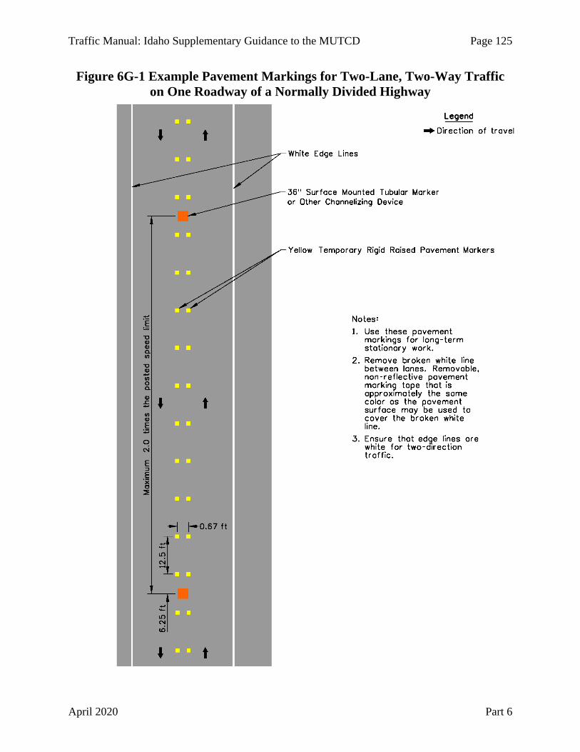
Traffic Manual: Idaho Supplementary Guidance to the MUTCD Page 125
April 2020 Part 6
Figure 6G-1 Example Pavement Markings for Two-Lane, Two-Way Traffic on One Roadway of a Normally Divided Highway

Page 126 Traffic Manual: Idaho Supplementary Guidance to the MUTCD
Part 6 April 2020
Section 6G.17 Interchanges
No supplemental information.
Section 6G.18 Work in the Vicinity of a Grade Crossing
No supplemental information.
Section 6G.19 Temporary Traffic Control During Nighttime Hours
No supplemental information.
CHAPTER 6H. TYPICAL APPLICATIONS Section 6H.01 Typical Applications
For MUTCD Table 6H-3, use the following speeds for low and high speed urban road types, unless otherwise determined by engineering judgment:
Use Figure 6G-1 with MUTCD Figure 6H-39.
CHAPTER 6I. CONTROL OF TRAFFIC THROUGH TRAFFIC INCIDENT MANAGEMENT AREAS
Section 6I.01 General
No supplemental information.
Section 6I.02 Major Traffic Incidents
No supplemental information.
Section 6I.03 Intermediate Traffic Incidents
No supplemental information.
Section 6I.04 Minor Traffic Incidents
No supplemental information.
Section 6I.05 Use of Emergency-Vehicle Lighting
No supplemental information.
Urban (Low Speed): 35 mph or lower Urban (High Speed): 40 mph or greater

Traffic Manual: Idaho Supplementary Guidance to the MUTCD Page 127
April 2020 Part 7
CHAPTER 7A. GENERAL Section 7A.01 Need for Standards
No supplementary information.
Section 7A.02 School Routes and Established School Crossings
No supplementary information.
Section 7A.03 School Crossing Control Criteria
No supplementary information.
Section 7A.04 Scope
No supplementary information.
CHAPTER 7B. SIGNS Section 7B.01 Size of School Signs
See IDAPA 39.03.41 – Rules Governing Traffic Control Devices. Remove the WHEN CHILDREN ARE PRESENT (S4-2P) sign from MUTCD Table 7B-1.
Section 7B.02 Illumination and Reflectorization
No supplementary information.
Section 7B.03 Position of Signs
No supplementary information.
Section 7B.04 Height of Signs
No supplementary information.
Section 7B.05 Installation of Signs
No supplementary information.
Section 7B.06 Lettering
No supplementary information.
Section 7B.07 Sign Color for School Warning Signs
No supplementary information.
PART 7 TRAFFIC CONTROL FOR SCHOOL AREAS

Page 128 Traffic Manual: Idaho Supplementary Guidance to the MUTCD
Part 7 April 2020
Section 7B.08 School Sign (S1-1) and Plaques
See IDAPA 39.03.41 – Rules Governing Traffic Control Devices. Remove the WHEN CHILDREN ARE PRESENT (S4-2P) sign from MUTCD Figure 7B-1.
Section 7B.09 School Zone Sign (S1-1) and Plaques (S4-3P, S4-7P) and END SCHOOL ZONE Sign (S5-2)
No supplementary information.
Section 7B.10 Higher Fines Zone Sign (R2-10, R2-11) and Plaques
Higher fines are imposed in Idaho for speed limit violations within a designated school zone (see Idaho statute 49-658). Use signs or plaques to indicate the beginning and end of a higher fines zone.
Section 7B.11 School Advance Crossing Assembly
In accordance with Idaho Statute 49-702, drivers must yield to a pedestrian crossing the highway within a crosswalk. Do not use the In-Street Pedestrian Crossing STOP HERE FOR PEDESTRIANS (R1-6a) sign at uncontrolled marked crosswalks. The R1-6a sign has been deleted from the Idaho adoption of the MUTCD through IDAPA 39.03.41 “Rules Governing Traffic Control Devices.”
Section 7B.12 School Crossing Assembly
In accordance with Idaho Statute 49-702, drivers must yield to a pedestrian crossing the highway within a crosswalk. Do not use the In-Street Pedestrian or Schoolchildren Crossing (R1-6a, R1-6c) signs at uncontrolled marked crosswalks. The R1-6a and R1-6c signs have been deleted from the Idaho adoption of the MUTCD through IDAPA 39.03.41 “Rules Governing Traffic Control Devices.”
Section 7B.13 School Bus Stop Ahead Sign (S3-1)
No supplementary information.
Section 7B.14 SCHOOL BUS TURN AHEAD Sign (S3-2)
No supplementary information.
Section 7B.15 School Speed Limit Assembly (S4-1P, S4-3P, S4-4P, S4-6P, S5-1) and END SCHOOL SPEED LIMIT Sign (S5-3)
Do not use the WHEN CHILDREN ARE PRESENT (S4-2P) plaque (see IDAPA 39.03.41 – Rules Governing Traffic Control Devices). Idaho has no statutory school zone speed limit or required speed limit reduction. Higher fines can be imposed by law enforcement officers in school zones for speed limit violations whether or not the speed limit is reduced (see Idaho statute 49-658).
Speed limit reductions in school zones on Idaho highways should be used sparingly. Refer to the ITE Traffic Control Devices Handbook for comprehensive treatment of reduced school speed limit zones. The remainder of this section is an application of the Traffic Control Devices Handbook guidance for use on Idaho highways.

Traffic Manual: Idaho Supplementary Guidance to the MUTCD Page 129
April 2020 Part 7
Driver compliance with reduced school speed limits is generally poor when the speed limit is set unreasonably low and there is a questionable relationship between pedestrian crashes and the reduced speed limit (see ITE Traffic Control Device Handbook).
Encourage schools to engage crossing guards, implement school bussing, or other measures before considering a reduced school speed limit zone or enhanced crossings. The speed limit should not normally be reduced in a school zone on a highway when one or more of the following situations are present:
• When the school is a High School or College
• When the school does not front the highway
• Where there are no school crossings established through a school route plan
• Where the walking routes are parallel to the highway
• Where fewer than 15 schoolchildren use the crossing one hour before or one hour after normal school hours
• Where school bussing is provided for school children across the highway from the school
• Where there is a crossing at a traffic control signal, pedestrian hybrid beacon, or STOP sign
• When the regular speed limit or the 85th percentile speed is 35 mph or less
• Where there are an adequate number of gaps for schoolchildren to cross
A reduced school speed limit zone may be implemented after other strategies have been tried, there is a multi-year history of reported crashes, or both. However, reduced school speed limits alone do not alleviate safety concerns or crash potential. When used prepare a traffic minute entry for the reduced school speed limit zone.
When used, keep reduced speed limit school zones as short as practical. Researchers have observed that the lowest vehicle speeds occur at a point between 15 to 30 percent into a school zone. Vehicle speeds tend to increase as the length of the reduced school speed limit zone increases.
The limits of a reduced school speed limit zone do not necessarily need to extend along the entire roadway frontage of the school property. Limit the length to 200 to 400 feet in advance a school crossing or the functional boundaries of school activities fronting the highway. School crossing locations, school driveways, or other school related activities fronting the highway have more relevance than school property boundaries.
Avoid extending reduced speed school zones beyond one block. When intersections are within reduced speed school zones, drivers turning onto the highway from cross streets are not informed about the reduced school speed limit. When traffic control signals are within a reduced school speed limit zone, drivers may forget about the reduced speed limit after stopping at and passing through the signal.
Base reduced school speed limit on a deviation from the posted speed limit or 85th percentile speed as shown in Table 7B-1.

Page 130 Traffic Manual: Idaho Supplementary Guidance to the MUTCD
Part 7 April 2020
Table 7B-1 Reduced School Speed Limit Based on Highway Speed Posted Speed Limit or 85th Percentile Speed
Suggested Reduced School Zone Speed Limit
Lower than 55 mph Not more than 15 mph below the posted speed limit or the 85th percentile speed, not to exceed 35 mph, and not lower than 25 mph.
55 mph or higher 35 mph
When used, reduced school speed limits should only be in effect on school days and during times immediately before and after school hours. Researchers have recommended that reduced school speed limits be in effect from 30 minutes before the school starting time until five minutes after the school starting time and from five minutes prior to the school dismissal bell until 30 minutes after the school’s dismissal bell. Do not use reduced school speed limits during scheduled breaks, weekends, or non-school day holidays.
A school speed limit assembly with the WHEN FLASHING (S4-4P) plaque and a flashing beacon is the most effective means of implementing a reduced speed limit. When flashers are not practical, indicate when the reduced school speed limit is in effect with the S4-1P plaque. Do not use the WHEN CHILDREN ARE PRESENT (S4-2P) plaque (see IDAPA 39.03.41 – Rules Governing Traffic Control Devices).
Remove reduced school speed limit zones when conditions change, such as changes to school bussing, enhancement of a crossing to a traffic control signal, pedestrian hybrid beacon, or STOP control, or closure of a school.
Section 7B.16 Reduced School Speed Limit Ahead Sign (S4-5, S4-5a)
No supplementary information.
Section 7B.17 Parking and Stopping Signs (R7 and R8 Series)
No supplementary information.
CHAPTER 7C. MARKINGS Section 7C.01 Functions and Limitations
No supplementary information.
Section 7C.02 Crosswalk Markings
Pavement markings for school crossings are an ITD responsibility unless addressed in a State/Local Maintenance Agreement.
Section 7C.03 Pavement Word, Symbol, and Arrow Markings
If used, place the SCHOOL XING pavement markings in advance of ITD approved crosswalks. Figure 7C-1 illustrates the dimensions and placement of the SCHOOL XING marking. In urban locations place the marking 200 feet upstream of the crosswalk, if practical. In rural locations, place the marking upstream of the crosswalk a distance in feet equal to ten times the posted speed limit, in mph, if practical.

Traffic Manual: Idaho Supplementary Guidance to the MUTCD Page 131
April 2020 Part 7
Figure 7C-1 School Crossing Pavement Markings

Page 132 Traffic Manual: Idaho Supplementary Guidance to the MUTCD
Part 7 April 2020
CHAPTER 7D. CROSSING SUPERVISION Section 7D.01 Types of Crossing Supervision
In accordance with Idaho Statue 33-1801, school district or school officers may authorize school safety patrols.
Section 7D.02 Adult Crossing Guards
The potential for pedestrian and vehicular conflicts occur only during parts of the day when school is in session. Conflicts at school crossings may be mitigated with adult crossing guards when more restrictive traffic control devices may not be desirable. The instruction, supervision and cost of either school safety patrols or adult crossing guards are the responsibility of school and community officials.
Section 7D.03 Qualifications of Adult Crossing Guards
No supplementary information.
Section 7D.04 Uniform of Adult Crossing Guards
No supplementary information.
Section 7D.05 Operating Procedures for Adult Crossing Guards
No supplementary information.

Traffic Manual: Idaho Supplementary Guidance to the MUTCD Page 133
April 2020 Part 8
CHAPTER 8A. GENERAL Section 8A.01 Introduction
See Idaho Statute Title 62, Chapter 3 for laws pertaining to highway-rail grade crossings on highways. Also refer to the ITD “Railroad Guide” and FHWA “Highway-Rail Grade Crossing Handbook.”
Section 8A.02 Use of Standard Devices, Systems, and Practices at Highway-rail Grade Crossings
No supplemental information.
Section 8A.03 Use of Standard Devices, Systems, and Practices at Highway-LRT Grade Crossings
No supplemental information.
Section 8A.04 Uniform Provisions
No supplemental information.
Section 8A.05 Grade Crossing Elimination
No supplemental information.
Section 8A.06 Illumination at Grade Crossings
No supplemental information.
Section 8A.07 Quiet Zone Treatments at Highway-Rail Grade Crossings
No supplemental information.
Section 8A.08 Temporary Traffic Control Zones
No supplemental information.
CHAPTER 8B. SIGNS AND MARKINGS Section 8B.01 Purpose
No supplemental information.
Section 8B.02 Size of Grade Crossing Signs
No supplemental information.
PART 8 TRAFFIC CONTROL FOR RAILROAD GRADE CROSSINGS

Page 134 Traffic Manual: Idaho Supplementary Guidance to the MUTCD
Part 8 April 2020
Section 8B.03 Grade Crossing (Crossbuck) Sign (R15-1) and Number of Tracks Plaque (R15-2P) at Active and Passive Grade Crossings
The railroad company is responsible for the installation and maintenance of the Grade Crossing (R15-1) sign, Number of Tracks (R15-2P) plaque, and YIELD (R1-2) or STOP (R1-1) signs. The highway agency (ITD on Idaho highways or a local agency on local roads) is responsible for traffic control devices that are outside the railroad right-of-way, such as advance warning signs and pavement markings. See the “Highway-Rail Grade Crossing Handbook.”
Do not install or replace IdaShield signs.
Section 8B.04 Crossbuck Assemblies with YIELD or STOP Signs at Passive Grade Crossings
The Idaho law requiring ITD and local road agencies to install STOP (R1-1) signs at passive highway-rail grade crossing was repealed in 2019. Railroad companies changed the STOP signs at most passive grade crossings to YIELD (R1-2) signs in 2019.
Prepare a Traffic Minute Entry, in accordance with Administrative Policy 5016 – Traffic Regulation, when STOP (R1-1) signs have been determined to be the appropriate traffic control device instead of YIELD (R1-2) signs through an engineering study at public passive highway-rail grade crossings on ITD highways.
Coordinate with the railroad company when studying passive grade crossings for STOP or YIELD sign traffic control device study. The objective of these engineering studies is to limit the use of STOP signs to locations where they are clearly appropriate. STOP sign compliance at passive crossings is poor without a specific hazard related to the crossing. See Section 17B.03 for a study outline.
Section 8B.05 Use of STOP (R1-1) or YIELD (R1-2) Signs without Crossbuck Signs at Highway-LRT Grade Crossings
No supplemental information.
Section 8B.06 Grade Crossing Advance Warning Signs (W10 Series)
No supplemental information.
Section 8B.07 EXEMPT Highway-Rail Grade Crossing Plaques (R15-3P, W10-1aP)
See IDAPA 39.03.41 – Rules Governing Traffic Control Devices – regarding Idaho law about exempt highway-rail crossings.
Idaho Statute 49-649 and Article 392.10 of the Federal Motor Carrier Safety Regulations require that certain vehicles stop at every railroad grade crossing. Some minimum-use crossings which have positive control such as a flagger and/or stop signs for trains or on industrial or spur lines may qualify as an “Exempt” crossing at which these specific vehicles are not required to stop.
To designate a crossing as exempt, coordinate with the operating railroad and obtain their written concurrence. Prepare a report that includes the AAR/DOT crossing number and recommendation to exempt the crossing. Obtain District Engineer approval and provide a copy

Traffic Manual: Idaho Supplementary Guidance to the MUTCD Page 135
April 2020 Part 8
of the approved report and railroad company concurrence to the Railroad/Utility Manager. When approved, install the EXEMPT plaques.
Section 8B.08 Turn Restrictions During Preemption
No supplemental information.
Section 8B.09 DO NOT STOP ON TRACKS Sign (R8-8)
No supplemental information.
Section 8B.10 TRACKS OUT OF SERVICE Sign (R8-9)
No supplemental information.
Section 8B.11 STOP HERE WHEN FLASHING Signs (R8-10, R8-10a)
No supplemental information.
Section 8B.12 STOP HERE ON RED Signs (R10-6, R10-6a)
No supplemental information.
Section 8B.13 Light Rail Transit Only Lane Signs (R15-4 Series)
No supplemental information.
Section 8B.14 Do Not Pass Light Rail Transit Signs (R15-5, R15-5a)
No supplemental information.
Section 8B.15 No Motor Vehicles On Tracks Signs (R15-6, R15-6a)
No supplemental information.
Section 8B.16 Divided Highway with Light Rail Transit Crossing Signs (R15-7 Series)
No supplemental information.
Section 8B.17 LOOK Sign (R15-8)
No supplemental information.
Section 8B.18 Emergency Notification Sign (I-13)
No supplemental information.
Section 8B.19 Light Rail Transit Approaching-Activated Blank-Out Warning Sign (W10-7)
No supplemental information.
Section 8B.20 TRAINS MAY EXCEED 80 MPH Sign (W10-8)
No supplemental information.

Page 136 Traffic Manual: Idaho Supplementary Guidance to the MUTCD
Part 8 April 2020
Section 8B.21 NO TRAIN HORN Sign or Plaque (W10-9, W10-9P)
No supplemental information.
Section 8B.22 NO GATES OR LIGHTS Plaque (W10-13P)
No supplemental information.
Section 8B.23 Low Ground Clearance Grade Crossing Sign (W10-5)
No supplemental information.
Section 8B.24 Storage Space Signs (W10-11, W10-11a, W10-11b)
No supplemental information.
Section 8B.25 Skewed Crossing Sign (W10-12)
No supplemental information.
Section 8B.26 Light Rail Transit Station Sign (I-12)
No supplemental information.
Section 8B.27 Pavement Markings
Generally, truck stopping lanes are not provided at crossings with active protection and are optional at crossings with passive control.
Section 8B.28 Stop and Yield Lines
No supplemental information.
Section 8B.29 Dynamic Envelope Markings
No supplemental information.
CHAPTER 8C. FLASHING-LIGHT SIGNALS, GATES, AND TRAFFIC CONTROL SIGNALS
Section 8C.01 Introduction
See Idaho Statutes 62-304A, 62-304B, and 62-304C for the funding and construction of active traffic control systems.
Section 8C.02 Flashing-Light Signals
No supplemental information.
Section 8C.03 Flashing-Light Signals at Highway-LRT Grade Crossings
No supplemental information.
Section 8C.04 Automatic Gates
No supplemental information.

Traffic Manual: Idaho Supplementary Guidance to the MUTCD Page 137
April 2020 Part 8
Section 8C.05 Use of Automatic Gates at LRT Grade Crossings
No supplemental information.
Section 8C.06 Four-Quadrant Gate Systems
No supplemental information.
Section 8C.07 Wayside Horn Systems
No supplemental information.
Section 8C.08 Rail Traffic Detection
No supplemental information.
Section 8C.09 Traffic Control Signals at or Near Highway-Rail Grade Crossings
No supplemental information.
Section 8C.10 Traffic Control Signals at or near Highway-LRT Grade Crossings
No supplemental information.
Section 8C.11 Use of Traffic Control Signals for Control of LRT Vehicles at Grade Crossings
No supplemental information.
Section 8C.12 Grade Crossings Within or In Close Proximity to Circular Intersections
No supplemental information.
Section 8C.13 Pedestrian and Bicycle Signals and Crossings at LRT Grade Crossings
No supplemental information.
CHAPTER 8D. PATHWAY GRADE CROSSINGS Section 8D.01 Purpose
No supplemental information.
Section 8D.02 Use of Standard Devices, Systems, and Practices
No supplemental information.
Section 8D.03 Pathway Grade Crossing Signs and Markings
No supplemental information.
Section 8D.04 Stop Lines, Edge Lines, and Detectable Warnings
No supplemental information.

Page 138 Traffic Manual: Idaho Supplementary Guidance to the MUTCD
Part 8 April 2020
Section 8D.05 Passive Devices for Pathway Grade Crossings
No supplemental information.
Section 8D.06 Active Traffic Control Systems for Pathway Grade Crossings
No supplemental information.

Traffic Manual: Idaho Supplementary Guidance to the MUTCD Page 139
April 2020 Part 9
CHAPTER 9A. GENERAL Section 9A.01 Requirements for Bicyclist Traffic Control Devices
No supplemental information.
Section 9A.02 Scope
No supplemental information.
Section 9A.03 Definitions Related to Bicycles
No supplemental information.
Section 9A.04 Maintenance
No supplemental information.
Section 9A.05 Relation to Other Documents
The most recent edition of the AASHTO “Guide for Development of Bicycle Facilities” may be referenced as an informational document in the development of signing and marking recommendations.
Section 9A.06 Placement Authority
No supplemental information.
Section 9A.07 Meaning of Standard, Guidance, Option, and Support
No supplemental information.
Section 9A.08 Colors
No supplemental information.
CHAPTER 9B. SIGNS Section 9B.01 Application and Placement of Signs
No supplemental information.
Section 9B.02 Design of Bicycle Signs
No supplemental information.
Section 9B.03 STOP and YIELD Signs (R1-1, R1-2)
No supplemental information Idaho Statute 49-720 allows a bicyclist approaching a STOP (R1-1) sign to slow down and proceed through the intersection without stopping after yielding to other traffic (see Section 2B.05).
PART 9 TRAFFIC CONTROL FOR BICYCLE FACILITIES

Page 140 Traffic Manual: Idaho Supplementary Guidance to the MUTCD
Part 9 April 2020
Section 9B.04 Bike Lane Signs and Plaques (R3-17, R3-17aP, R3-17bP)
No supplemental information.
Section 9B.05 BEGIN RIGHT TURN LANE YIELD TO BIKES Sign (R4-4)
No supplemental information.
Section 9B.06 Bicycles May Use Full Lane Sign (R4-11)
No supplemental information.
Section 9B.07 Bicycle WRONG WAY Sign and RIDE WITH TRAFFIC Plaque (R5-1b, R9-3cP)
No supplemental information.
Section 9B.08 NO MOTOR VEHICLES Sign (R5-3)
No supplemental information.
Section 9B.09 Selective Exclusion Sign
No supplemental information.
Section 9B.10 No Parking Bike Lane Signs (R7-9, R7-9a)
No supplemental information.
Section 9B.11 Bicycle Regulatory Signs (R9-5, R9-6, R10-4, R10-24, R10-25, and R10-26)
No supplemental information.
Section 9B.12 Shared-Use Path Restriction Sign (R9-7)
No supplemental information.
Section 9B.13 Bicycle Signal Actuation Sign (R10-22)
No supplemental information.
Section 9B.14 Other Regulatory Signs
No supplemental information.
Section 9B.15 Turn or Curve Warning Signs (W1 Series)
No supplemental information.
Section 9B.16 Intersection Warning Signs (W2 Series)
No supplemental information.
Section 9B.17 Bicycle Surface Condition Warning Sign (W8-10)
No supplemental information.

Traffic Manual: Idaho Supplementary Guidance to the MUTCD Page 141
April 2020 Part 9
Section 9B.18 Bicycle Warning and Combined Bicycle/Pedestrian Signs (W11-1 and W11-15)
No supplemental information.
Section 9B.19 Other Bicycle Warning Signs
No supplemental information.
Section 9B.20 Bicycle Guide Signs (D1-1b, D1-1c, D1-2b, D1-2c, D1-3b, D1-3c, D11-1, D11-1c)
No supplemental information.
Section 9B.21 Bicycle Route Signs (M1-8, M1-8a, M1-9)
ITD has received approval to use the alternate design of the U.S. Bicycle Route (M1-9) sign (see Figure 9B-1). This alternate sign design should be used in place of the M1-9 sign shown in the 2009 MUTCD.
Figure 9B-1 U.S. Bicycle Route Sign
M1-9
Section 9B.22 Bicycle Route Sign Auxiliary Plaques
No supplemental information.
Section 9B.23 Bicycle Parking Area Signs (D4-3)
No supplemental information.

Page 142 Traffic Manual: Idaho Supplementary Guidance to the MUTCD
Part 9 April 2020
Section 9B.24 Reference Location Sign (D10-1 through D10-3) and Intermediate Reference Location Signs (D10-1a through D10-3a)
No supplemental information.
Section 9B.25 Mode-Specific Guide Signs for Shared-Use Path (D11-1a, D11-2, D11-3, D11-4)
No supplemental information.
Section 9B.26 Object Markers
No supplemental information.
CHAPTER 9C. MARKINGS Section 9C.01 Functions of Markings
No supplemental information.
Section 9C.02 General Principles
No supplemental information.
Section 9C.03 Marking Patterns and Colors on Shared-Use Paths
No supplemental information.
Section 9C.04 Markings For Bicycle Lanes
Do not use green bicycle lane pavement markings on the state highway system. ITD has not obtained nor requested permission from FHWA through the MUTCD interim approval process (see Section 1A.10) to use green pavement markings. Some local agencies have received permission to use green colored pavement markings on their system, but their approval does not apply to state highways running through their jurisdictions.
Section 9C.05 Bicycle Detector Symbol
No supplemental information.
Section 9C.06 Pavement Markings for Obstructions
No supplemental information.
Section 9C.07 Shared Lane Marking
No supplemental information.

Traffic Manual: Idaho Supplementary Guidance to the MUTCD Page 143
April 2020 Part 9
CHAPTER 9D. SIGNALS Section 9D.01 Application
No supplemental information.
Section 9D.02 Signal Operations for Bicycles
Idaho statute 49-720(2), known informally as the Idaho bicycle law, allows bicyclists to enter a signal controlled intersection on a red indication after stopping and yielding to all other traffic (see Section 4D.04).
Do not use bicycle signal faces on the state highway system. ITD has not obtained nor requested permission from FHWA through the MUTCD interim approval process (see Section 1A.10) to use bicycle signal faces and the Idaho bicycle law essentially eliminates the need for bicycle signal faces. Some local agencies have received permission to use bicycle signal faces, but their approval does not apply to state highways running through their jurisdictions.

Page 144 Traffic Manual: Idaho Supplementary Guidance to the MUTCD
Part 10 April 2020
Part 10 is reserved for future use.
PART 10 Reserved for Future Use

Traffic Manual: Idaho Supplementary Guidance to the MUTCD Page 145
April 2020 Part 11
Part 11 is reserved for future use.
PART 11 Reserved for Future Use

Page 146 Traffic Manual: Idaho Supplementary Guidance to the MUTCD
Part 12 April 2020
Part 12 is reserved for future use.
PART 12 Reserved for Future Use

Traffic Manual: Idaho Supplementary Guidance to the MUTCD Page 147
April 2020 Part 13
Part 13 is reserved for future use.
PART 13 Reserved for Future Use

Page 148 Traffic Manual: Idaho Supplementary Guidance to the MUTCD
Part 14 April 2020
Part 14 is reserved for future use.
PART 14 Reserved for Future Use

Traffic Manual: Idaho Supplementary Guidance to the MUTCD Page 149
April 2020 Part 15
CHAPTER 15A. GENERAL Section 15A.01 General
Highway lighting can improve nighttime visibility of the highway, other highway users, and environmental conditions.
Use the AASHTO “Roadway Lighting Design Guide” when determining lighting use and location (see Administrative Policy 5016 – Traffic Regulation). The Illuminating Engineering Society’s (IES) “RP-8 Recommended Practice for Lighting Roadway and Parking Facilities” publication and the “FHWA Lighting Handbook” are additional resources. “NCHRP Report 828 – Guidelines for Nighttime Visibility of Overhead signs” provides design information for lighting overhead signs.
CHAPTER 15B. LIGHTING DESIGN, INSTALLATION, OPERATION, AND MAINTENANCE
Section 15B.01 Lighting Costs
The costs associated with highway lighting include design, installation, operation, and maintenance of the lighting system.
In accordance with Administrative policy 5016 – Traffic Regulation – ITD is responsible for the costs of lighting on Interstate highways and at rural interchanges.
If a local jurisdiction requests additional highway lighting, the associated costs are paid by that local jurisdiction (see Administrative policy 5016 – Traffic Regulation).
Section 15B.02 Lighting Agreements
In accordance with Administrative policy 5016 – Traffic Regulation, – ITD can enter into a written agreement with other governmental agencies or private entities if that agency or entity requests special lighting devices. The agreement must include arrangements for the installation, operation, and maintenance of the lighting.
ITD and electric utility companies may desire to enter into an energy supply agreement for lighting installations maintained and operated by ITD. The agreement should include information regarding the number and type of luminaires and the date that the system is energized.
Enter into an agreement with the railroad company if the lighting system is located in or crosses railroad right-of-way.
Section 15B.03 Highway Lighting Design
ITD uses AGi32 computer software to assist with the design of lighting systems and to perform calculations to determine the system characteristics. Design lighting systems in accordance with
PART 15 LIGHTING

Page 150 Traffic Manual: Idaho Supplementary Guidance to the MUTCD
Part 15 April 2020
the AASHTO “Roadway Lighting Design Guide.” Document the lighting design criteria, and conductor gauge calculations.
Install lighting at new signalized intersections and roundabouts. Lighting is optional on temporary traffic control signals and emergency-vehicle traffic control signals. Distribute power through a multiple circuit underground electrical distribution system. Limit maximum branch circuit potential to 240 volts with a maximum voltage drop of five percent. The minimum circuit feeder conductor gauge size should be #8 THWN and should not exceed gauge size #2 THWN.
Include the following on lighting plans:
• Lighting pole locations, junction boxes, and highway features • Conduit routing, size, circuit number, conductors and conductor sizes • Type of pole, mounting height, mast arm length, lamp, voltage, distribution, and wattage • Power source • Electrical service pedestal type
Section 15B.04 Lighting Poles and Foundations
Refer to the AASHTO “Roadside Design Guide” for the design and application of breakaway lighting poles (called luminaire supports in the “Roadside Design Guide”).
Contact the local power company for vertical and horizontal clearance requirements or guidance on minimum distances between lighting poles and overhead power lines.
See the ITD Standard Drawings for foundation details.
Contact the ITD Bridge section when designing lighting poles on bridge structures.
Section 15B.05 Overhead Sign Lighting
If overhead signs are to be illuminated, design the lighting in accordance with the AASHTO “Roadway Lighting Design Guide” and Appendix D of “NCHRP Report 828 – Guidelines for Nighttime Visibility of Overhead signs.”

Traffic Manual: Idaho Supplementary Guidance to the MUTCD Page 151
April 2020 Part 16
CHAPTER 16A. GENERAL Section 16A.01 General
Intelligent Transportation Systems (ITS) improve safety, mobility, and economic opportunity through collecting real time data and video images, broadcasting traveler information on phone, web, and roadside devices, and sharing data with external customers.
The FHWA provides many ITS resources through the “Regional ITS Architecture Guidance Document,” the “Systems Engineering Guidebook for Intelligent Transportation Systems,” and through various USDOT and FHWA webpages. Idaho and regional ITS architectures are described in the “Idaho Statewide ITS Strategic Plan Update.”
Section 16A.02 ITS Assets
The inventory of ITS assets includes the following:
• Changeable Message Signs (CMS)
• Road Weather Information Systems (RWIS)
• Closed Circuit Television Cameras (CCTV)
• Bluetooth Detectors
• Variable Speed Limits
• Dedicated Short Range Communications radios (DSRC)
• ITS Network Control Software
CHAPTER 16B. CHANGEABLE MESSAGE SIGNS (CMS) Section 16B.01 General
ITD Changeable Message Signs (CMS) fall into two size classes, freeway walk-in sign cabinets that display 18 inch high characters and arterial highway lift front or brick face signs that display 12 inch high characters. All ITD CMS are full matrix displays using amber LEDs. At some point in the future ITD may transition to full matrix full color LED displays where highway icons can be posted in lieu of highway text, and international symbols can be substituted for verbiage.
Section 16B.02 Design Guidance
Once a location is identified for a proposed CMS that can provide important information for drivers to make informed driving decisions, the power and communications need to be selected.
All ITD CMS use grid power; however as technology advances there may be opportunities to explore site generated power options, such as solar, wind, propane generators etc.
PART 16 INTELLIGENT TRANSPORTATION SYSTEMS
Page 152 Traffic Manual: Idaho Supplementary Guidance to the MUTCD
Part 16 April 2020
The minimum display pixel matrix for CMS should be 27 x 105, allowing display of three lines of text of 17 characters per line, using a 5 x 7 pixel font.
All CMS purchased must have certified test reports attesting to compliance with National Transportation Communications for Intelligent Transportation System Protocol (NTCIP) communications standards. In addition, all CMS must pass a demonstration test on ITD’s ITS Network Control Software.
All fixed CMS are controlled remotely using the ITS Network Control Software, and can be controlled locally using a laptop computer connected to the sign controller. Communications between the ITS Network Control Software and the CMS controller may be either fiber optics, 3G/4G cellular, DSL, or land line. NTCIP Control commands do not require high bandwidth so although fiber optic communications is preferred for its reliability and speed, 3G/4G cellular communications work fine in good cell coverage areas.
CHAPTER 16C. ROAD WEATHER INFORMATION SYSTEMS (RWIS) Section 16C.01 General
Road Weather Information Systems (RWIS) sites monitor road weather and provide critical data and video images during winter driving conditions. The environmental and road condition data and associated video images are used by ITD Operations staff to guide winter operations treatment material selection, distribution rates and treatment timing. Winter Performance Measures are derived from the RWIS data and each foreman area is rated on their performance.
The sites are polled every fifteen minutes by Vaisala under a data hosting contract. RWIS data and video images are shared with the public on the full featured 511 website and 511 smart phone application. Television stations statewide broadcast RWIS camera snapshot images on their weather segments during the winter season.
Section 16C.02 Design Guidance
ITD has standardized on Vaisala sensors for all RWIS sites, including the non-invasive pavement sensors that measure road surface temperature, layer type, layer thickness, and feed this data to the algorithm that calculates road grip.
RWIS sites may use grid power or locally generated power. Communications may be either 3G/4G cellular, DSL, or dial up. Cellular communications are preferred.
Video cameras being used for RWIS sites are the Mobotix M15 for solar sites and the Axis Q6045E (high definition) for the grid power sites.
A typical site will include the DST111 and DSC111 pavement sensors, a PWD present weather detector, a wind sensor, an HMP temperature/humidity, barometric pressure sensor, a visibility sensor, video camera(s), and infrared illuminators for nighttime lighting. A remote processing unit receives the signals from the sensors and uploads the data and video images when polled by Vaisala.

Traffic Manual: Idaho Supplementary Guidance to the MUTCD Page 153
April 2020 Part 16
CHAPTER 16D. CLOSED CIRCUIT TELEVISION CAMERAS (CCTV) Section 16D.01 General
ITD utilizes Closed Circuit Television (CCTV) cameras for traffic surveillance and assisting with incident management. The primary operator of the ITD camera network is Idaho Health and Welfare, EMS Bureau, from the State Communications Center in Meridian, ID. Video is also fed to the Idaho State Police (Meridian and Coeur d’Alene), Kootenai County 911, and ITD HQ and District offices. During local news segments, television stations in the Boise area also broadcast streaming video from ITD cameras.
Section 16D.02 Design Guidance
ITD has standardized on the Axis Q6042-E standard definition dome camera. When sufficient bandwidth becomes available it may be beneficial to upgrade to HD camera technology.
Power for the cameras is grid sourced. Communications options are pretty limited for streaming video, either fiber optics or 4G cellular (lower frame rate and resolution).
Mounting options for the cameras are 50 foot MG2 poles with integral lowering device, or fixed mounting on signal structures or luminaire poles. Camera dome cleaning is most efficient when using the MG2 lowering devices.
CHAPTER 16E. BLUETOOTH DETECTORS Section 16E.01 General
Travel time is collected on a few highway segments using Bluetooth detectors, by time stamping a detected MAC address at one location and comparing the elapsed time for a similar detection at the second location. Knowing the distance between sites and the elapsed time makes it possible to calculate the travel speed as well as the travel time. ITD has Bluetooth detectors on I-84 and I-184 in the Treasure Valley, and on US 95 in Coeur d’Alene. TrafficCast is the data host for the BlueTOAD detectors.
The detectors use 3G cellular communications and battery power with solar charging.
Section 16E.02 Design Guidance
If these detectors are deployed to monitor work zone delay, they need to be placed well outside of the expected traffic queue in order to collect accurate data.
The units are self-contained and easily deployed on existing structures.
CHAPTER 16F. VARIABLE SPEED LIMIT ZONES Section 16F.01 General
At some locations around the state there may be a desire to vary the speed limit due to hazardous driving conditions. These conditions may include limited visibility, low grip, work zone activities, and high winds. Posting speed limits on the variable speed limit signs can be changed remotely, locally or driven by environmental sensor data.

Page 154 Traffic Manual: Idaho Supplementary Guidance to the MUTCD
Part 16 April 2020
Section 16F.02 Design Guidance
Existing RWIS sites may be leveraged in deploying a variable speed limit zone, or additional sensors may be needed if the RWIS location doesn’t mirror the highway zone being considered.
CHAPTER 16G. DEDICATED SHORT RANGE COMMUNICATIONS (DSRC) RADIOS
Section 16G.01 General
ITD has begun a partnership with the Idaho National Laboratory (INL) for research into Connected Vehicle Technology, deployed on the INL bus fleet, INL Scout vehicles, ITD snowplows, and at roadside locations. The technology uses Dedicated Short Range Communications (DSRC) 5.9 GHz radio communications to send and receive data with low latency and high bandwidth, to enable safety, mobility, and operational applications. A back office server is needed to archive the data and provide computing power.
Section 16G.02 Design Guidance
The roadside deployment requires an elevated structure to mount the DSRC unit, power and 3G/4G cellular communications for backhaul to the back office server. Existing ITS sites can be leveraged to lower the installation cost of roadside DSRC radios.
CHAPTER 16H. ITS NETWORK CONTROL SOFTWARE Section 16H.01 General
ITD has an existing ITS Network Control Software system called iNET, developed by Parsons. It has several modules for controlling various devices and applications. ITD has purchased the CCTV and CMS control modules, along with the Center to Center application for data sharing. Other modules that may be of interest in the future are the Weather Detection and Notification System and the Travel Time Information System.
Section 16H.02 Design Guidance
Test CMS and CCTV equipment using iNET prior to purchase and during installation.
CHAPTER 16I. SYSTEMS ENGINEERING Section 16I.01 General
A Systems Engineering (SE) analysis is required for each project that includes Intelligent Transportation Systems components.
SE guidance can be found in the “Systems Engineering Guidebook for Intelligent Transportation Systems” produced by the FHWA California Division and CalTrans, through the U.S. Department of Transportation’s (USDOT) ITS website, and through the FHWA California Division website.

Traffic Manual: Idaho Supplementary Guidance to the MUTCD Page 155
April 2020 Part 16
Section 16I.02 Systems Engineering (SE) Analysis (ITS Project Development Process)
The SE analysis, according to the FHWA ITS Final Rule, is a structured process for arriving at a final design of a system. The final design is selected from a number of alternatives that would accomplish the same objectives and considers the total life-cycle of the project including not only the technical merits of potential solutions but also the costs and relative value of alternatives.
The SE analysis for ITS project development and deployment of integrated transportation systems requires the project developer to consider all phases of the ITS system’s lifecycle: planning, requirements, design, procurement, implementation, deployment, operations, and maintenance.
Using the SE approach will help ensure the technology based projects are completed on time, on budget, and satisfy the user’s requirements. The SE process is required for all federal-aid ITS projects, regardless of size or complexity. However, the amount of SE analysis shall be commensurate with the project scope and technical complexity.
ITS projects exempt from the requirement of the SE process are: 1) those that do not use federal funding and 2) ITS expansions that do not add new functionality (upgrade to an existing traffic signal, installation of an isolated traffic signal, traffic signal timing project with no new hardware or software, studies or plans whose product is only a document, routine operations with no new hardware or software).
In accordance with 23 CFR 940.11 (Project Implementation), address the following through the SE process:
1. Identification of portions of the Regional Architecture (RA) being implemented or if a RA does not exist, the applicable portions of the National ITS Architecture
2. Identification of participating agencies and their roles and responsibilities 3. Requirements definitions 4. Analysis of alternative system configurations and technology options to meet
requirements 5. Procurement options 6. Identification of applicable ITS standards and testing procedures 7. Procedures and resources necessary for operation and management of the system
As shown in Figure 16I-1, FHWA recommends the Vee Model as the preferred systems engineering approach for ITS projects. The Vee Model above, shows the SE Process that covers the entire life cycle of an ITS project, from planning to design, operations, and maintenance. The process translates user needs into ITS system requirements and then into an ITS system design.

Page 156 Traffic Manual: Idaho Supplementary Guidance to the MUTCD
Part 16 April 2020
The objectives of the SE Process are to ensure ITS projects are completed:
1. On-time (i.e. avoid schedule overruns) 2. Within budget (i.e. reduce the risk of cost) 3. With satisfied user’s needs (i.e. system functionality that meets user’s expectation) 4. With high level of stakeholder participation 5. With good system documentation 6. Using a system that can evolve with a minimal redesign
Figure 16I-1 Systems Engineering Vee Model
Section 16I.03 Systems Engineering (SE) Analysis Documentation
Document SE analysis with the following outline:
Name of Project: Name of Regional ITS Architecture:
1. Identification of portions of the regional ITS architecture being implemented [Identify which user services, physical subsystems, information flows, and market packages are being completed as part of the project and how these pieces are part of the regional architecture.]

Traffic Manual: Idaho Supplementary Guidance to the MUTCD Page 157
April 2020 Part 16
2. Identification of participating agencies roles and responsibilities (concepts of operation) [For the user services to be implemented, define the high-level operations of the system, including where the system will be used, functions of the system capabilities, performance parameters, the life cycle of the system, and who will operate and maintain the system. Establish requirements or agreements on information sharing and traffic device control responsibilities.]
3. Requirements definitions [Based on the concept of operations, define the “what” and not “how” of the system. The applicable high-level functional requirements from the Regional Architecture (RA) are a good starting point for discussion.]
4. Analysis of alternative system configurations and technology options to meet requirements [The analysis of system alternatives should outline the strengths and weaknesses, technical feasibility, institutional compatibility, and life cycle costs of each alternative.]
5. Procurement options [Some procurement (contracting) options to consider include: consultant design/low bid contractor, systems manager, systems integrator, task order, and design/build. Deciding on the best procurement option should consider the level of agency participation, compatibility with existing procurement methods, role of system integrator, and life cycle costs.]
6. Identification of applicable ITS standards and testing procedures [Include documentation on which standards will be incorporated into the system design and justification for any applicable standards not incorporated. The standards report from the RA is a good starting point for discussion.]
7. Procedures and resources necessary for operations and management of the system [In addition to the above concept of operations, document any internal policies or procedures necessary to recognize and incorporate the new system into the current operations and decision-making processes. Resources necessary to support continued operations, including staffing and training must also be recognized early and be provided for. Such resources must also be provided to support necessary maintenance and upkeep to ensure continued system viability.]

Page 158 Traffic Manual: Idaho Supplementary Guidance to the MUTCD
Part 16 April 2020
This Page Intentionally Left Blank

Traffic Manual: Idaho Supplementary Guidance to the MUTCD Page 159
April 2020 Part 17
CHAPTER 17A. GENERAL Section 17A.01 Introduction
The Institute of Transportation Engineers’ (ITE) “Manual of Transportation Engineering Studies” describes how to conduct transportation engineering studies in the field for spot locations, segments and networks, multimodal studies, asset management, safety, and planning and access management. The ITE manual focuses on planning the study, preparing for field data collection, executing the data collection plan, and compiling, reducing, and analyzing the data as well as presenting the study results orally or in written form. Other resources such as the ITE “Traffic Engineering Handbook,” ITE “Traffic Control Devices Handbook,” and others referenced in this part also provide information about conducting transportation engineering studies.
CHAPTER 17B. SPOT LOCATION STUDIES Section 17B.01 General
Spot location studies include volume studies, speed and delay studies, intersection and driveway studies, and traffic control device studies. Refer to the ITE “Manual of Transportation Engineering Studies” for descriptions about how to conduct these types of studies.
Section 17B.02 Speed Zone Studies
Idaho Statute 49-201(4) gives the Idaho Transportation Board authority to determine and declare maximum and minimum speed limits for the state highway or interstate highway systems based on engineering studies. The Transportation Board has authority to set speed limits on all highways. Local jurisdictions have authority to set speed limits on non-highway roads.
Statutory speed limits are defined in Idaho Statute 49-201(4) as 75 mph on interstate highways and 65 mph on state highways. The statute allows the Transportation Board to exceed the statutory speed limits and post speed limits on interstate highways at 80 mph and at 70 mph on state highways.
The Transportation Board delegates the authority to set speed limits up to the statutory speed limit to the Districts through Board Policy 4016 – Traffic Regulation and Administrative Policy 5016 – Traffic Regulation. The Transportation Board retains the authority to approve 80 mph interstate speed limits and 70 mph speed limits on other highways. Prepare traffic minute entries for speed zones as described in IDAPA 39.03.65 “Rules Governing Traffic Minute Entries,” and Administrative Policy 5016 – Traffic Regulation.
PART 17 TRANSPORTATION ENGINEERING STUDIES

Page 160 Traffic Manual: Idaho Supplementary Guidance to the MUTCD
Part 17 April 2020
Speed data is typically collected at spot locations and is then used to set speed limits on highway segments. Data collection methods and sample size requirements are described in the ITE “Manual of Transportation Engineering Studies.” Refine the data to eliminate non-free-flowing vehicles.
Use MUTCD Section 2B.13, the ITE “Traffic Engineering Handbook,” the FHWA publication “Methods and Practices for Setting Speed Limits: An Informational Report” or other engineering resources for practices and methodologies used to establish speed limits.
The expert approach described in “Methods and Practices for Setting Speed Limits: An Informational Report” uses FHWA’s USLIMITS2 online program. The program can be used to identify the appropriate speed limit, or to supplement the engineering approach that is described in the informational report. Due to the way USLIMITS2 was developed, the program will not recommend a speed limit higher than 75 mph on a limited access freeway, higher than 65 mph for road sections in an undeveloped area, or higher than 50 for road sections in a developed area. This does not imply that speed limits cannot be set to a higher maximum speed for these types of facilities; only that the USLIMITS2 program will not recommend a higher speed limit.
Speed limits can be established for different times of day, different types of vehicles, varying weather conditions, can be variable (see Idaho Statute 49-201(4)), or to establish minimum speed limits (see Idaho Statute 49-202(22)). However, regulatory speed limits should not be used instead of appropriately designed advisory speeds.
In accordance with Idaho Statute 49-654(3), the speed limit for trucks (five or more axles and over 26,000 lbs.) on non-urban interstate highways cannot be less than ten mph lower than the posted speed limit for other vehicles. Speed limits for truck speeds on interstate highways in urban areas cannot exceed 65 mph.
Use the following outline to develop the engineering study report:
1. Executive Summary
a. Prepare an executive summary of the pertinent data and speed limit recommendation. Provide Figures or Tables as appropriate.
2. Previous Studies
a. Has a speed study been performed for the study area? What data was collected and what were the recommendations of the previous study? Provide Figures or Tables as appropriate.
3. Statutory Speed Limit
a. What is the statutory speed limit for the highway or roadway being studied? Provide Figures or Tables as appropriate.
4. Study Area
a. Describe the segment of highway that was studied. Provide the highway number, the mile posts, descriptive features (such as intersecting roads, rivers, etc.), or
Traffic Manual: Idaho Supplementary Guidance to the MUTCD Page 161
April 2020 Part 17
other pertinent descriptions. Describe the extents of the study area and why those extents were chosen. Provide Figures or Tables as appropriate.
5. Speed Distribution of Free-Flowing Vehicles
a. Perform an engineering speed zone study of free-flowing vehicles. Describe how the study was performed. How were non-free-flowing vehicles excluded from the data?
b. What is the observed 85th percentile speed of free-flowing vehicles? What is the observed pace? Provide Figures or Tables as appropriate.
c. How does the speed study compare with previous studies of the same area? Explain possible reasons for differences.
6. Crash Data
a. Investigate crash data in the study area for at least a 12-month period (preferably 3 to 5 years).
b. Are there highway or roadway improvements that can or have been made to address the reported crashes?
c. Calculate the crash rate for all crashes and for fatal and injury crashes. How do the crash rates compare with the crash rates of similar highways or roadways? Provide Figures or Tables as appropriate.
7. Highway or Road Characteristics
a. Describe the highway or roadway characteristics. Describe features such as lane widths, curb or shoulder condition, grade, alignment, median type, and sight distance. Provide Figures or Tables as appropriate.
Note: Highway or road characteristics are typically not reasons for lowering the speed limit. Adverse effects from highway or roadway characteristics are reflected in speed and crash data.
8. Highway or Road Context
a. Describe the highway or road context such as roadside development and environment including number of driveways and land use, functional classification, parking practices, presence of sidewalks/bicycle facilities. Provide Figures or Tables as appropriate.
Note: Highway or road context is typically not a reason for lowering the speed limit. Adverse effects from highway or roadway context are reflected in speed and crash data.
9. Highway or Road Users
a. Describe observed non-motor vehicle highway or road users such as pedestrian activity, bicycle activity. Provide Figures or Tables as appropriate.

Page 162 Traffic Manual: Idaho Supplementary Guidance to the MUTCD
Part 17 April 2020
10. Speed Limit Recommendation
a. Recommend a posted speed limit, as a multiple of 5 mph, based on the speeddistribution of free-flowing vehicles, crash data, highway or road characteristics,highway or road context, and highway or road users. The speed limitrecommendation should be within 5 mph of the 85th-percentile speed of free-flowing traffic.
b. Describe the proposed speed zone extents and why the selected boundaries areappropriate.
c. Provide figures, such as line graphs, to depict the existing and recommendedspeed limits and speed zone extents.
11. Expert Method Verification
a. Use USLIMITS2 to check the speed limit recommendation. Adjust therecommended speed limit if necessary. Provide the USLIMITS2 output in thereport.
Section 17B.03 Traffic Control Device Studies
Idaho Statute 49-202(20) directs ITD to place and maintain traffic control devices on the state highway system. The MUTCD contains warrants or application guidelines for signs, pavement markings, traffic control signals, and other traffic control devices.
The ITE “Manual of Transportation Engineering Studies” contains information on establishing the need for traffic control devices, removing unnecessary traffic control devices, and evaluating the effectiveness and condition of traffic control devices.
The following is an outline to develop the engineering study report for a STOP (R1-1) or YIELD (R1-2) sign traffic control device study at public passive highway-rail grade crossings (see Section 8B.04):
1. Line of sight
a. Evaluate the line of sight for a highway/roadway vehicle to an approaching train (see Figure 17B-1 and Table 17B-1 and Intersection Case C1 in AASHTO “A Policy on Geometric Design of Highways and Streets”). Is the line of sight restricted such that an approaching vehicle traffic is required to substantially reduce speed (more than 60 percent from the posted speed limit) to see an approaching train? Are there terrain features that restrict the line of sight?
b. Is the crossing skewed (angle less than 60 degrees) that makes it difficult for motorists to look both ways for approaching trains?
c. If the line of sight is limited, can the line of sight be improved by removing obstacles or vegetation?

Traffic Manual: Idaho Supplementary Guidance to the MUTCD Page 163
April 2020 Part 17
Figure 17B-1 Sight Triangle
Table 17B-1 Sight Triangle Distances Distance A: Length of Sight Triangle Leg along Highway/Roadway (ft)
Highway/Roadway Speed (mph) 25 30 35 40 45 50 55 60 65 70 130 160 195 235 275 320 370 420 470 530
Distance B: Length of Sight Triangle Leg along Railroad Tracks (ft) Highway/Roadway Speed (mph)
25 30 35 40 45 50 55 60 65 70
Trai
n Sp
eed
(mph
) 10 85 85 87 89 91 94 97 101 104 108 20 171 171 173 177 182 188 195 201 209 216 30 256 256 260 266 274 282 292 302 313 324 40 341 341 346 354 365 376 389 403 417 432 50 427 427 433 443 456 471 487 504 521 540 60 512 512 519 532 547 565 584 604 626 648 70 597 597 606 620 638 659 681 705 730 756
* assuming the vehicle crosses one set of Railroad tracks
Page 164 Traffic Manual: Idaho Supplementary Guidance to the MUTCD
Part 17 April 2020
2. Number of tracks
a. Does the highway or roadway cross more than two main tracks?
3. Train volumes
a. Do more than four trains per day pass through the crossing on five or more days each week? Is it likely that there will be two trains using the same crossing at the same time?
4. Highway or Roadway volumes
a. Do not use STOP signs when the average daily traffic of the crossing is 2,000 vehicles or more.
5. Speed of trains
a. Is the measured speed of crossing trains 70 mph or greater?
6. Crash history
a. Have there been multiple train and vehicle collisions in the last 5 to 10 years? What was the cause of those crashes?
7. Other considerations
a. Do trains regularly transport significant quantities of hazardous materials?
CHAPTER 17C. SEGMENT AND NETWORK STUDIES Section 17C.01 General
Segment and network studies include travel-time, and delay studies along corridors, freeway and managed lane studies, and simulation studies. Refer to the ITE “Manual of Transportation Engineering Studies” for descriptions about how to conduct these types of studies.
CHAPTER 17D. MULTIMODAL STUDIES Section 17D.01 General
Multimodal studies include pedestrian and bicycle studies, public transportation studies, and goods movement studies. Refer to the ITE “Manual of Transportation Engineering Studies” for descriptions about how to conduct these types of studies.
CHAPTER 17E. ASSET MANAGEMENT STUDIES Section 17E.01 General
Asset management studies include inventories and parking studies. Refer to the ITE “Manual of Transportation Engineering Studies” for descriptions about how to conduct these types of studies.
Section 17E.02 Parking Studies
ITD parking studies consist of evaluating rural parking prohibitions and urban angle parking.

Traffic Manual: Idaho Supplementary Guidance to the MUTCD Page 165
April 2020 Part 17
In accordance with Idaho Statute 49-202(28), ITD and local agencies can restrict stopping, standing, or parking of vehicles with traffic control devices. Restrict parking where stopping, standing, or parking is dangerous to those using the highway or unduly interferes with traffic movement. Document rural parking restrictions in accordance with Administrative Policy 5016 – Traffic Regulation.
Idaho Statute 49-661 prohibits angle parking on state highways unless ITD determines that angle parking will not interfere with the movement of traffic. Document urban angle parking in accordance with Administrative Policy 5016 – Traffic Regulation.
CHAPTER 17F. SAFETY STUDIES Section 17F.01 General
Safety studies include the collection of crash information, traffic collision studies, alternative safety studies such as road safety audits, and roadway lighting studies. Refer to the ITE “Manual of Transportation Engineering Studies” for descriptions about how to conduct these types of studies.
Section 17F.02 Traffic Hazard Investigation
Idaho Statute 49-1315 addresses the investigation of crashes resulting in death, injury, or property damage where an investigation or judicial action finds that a physical traffic hazard causes or was responsible for causing the crash. If the investigating traffic enforcement officer or presiding judicial officer provides their written findings to ITD for a crash on the state highway system, then ITD has sixty days to investigate and report on the purported traffic hazard. In the report, explain the hazard and propose mitigating measures, how the hazard has been mitigated, or why no action is to be taken. Provide the report to the investigating traffic enforcement officer or presiding judicial officer and the board of county commissioners.
Section 17F.03 Road Safety Audits
Refer to the ITD “Road Safety Audit Manual.”
CHAPTER 17G. PLANNING STUDIES Section 17G.01 General
Planning studies include general transportation planning, environmental impacts of transportation, and traffic access and impact studies. Refer to the ITE “Manual of Transportation Engineering Studies” for descriptions about how to conduct these types of studies.
Section 17G.02 Traffic Impact Studies
Requirements for traffic impact studies are described in IDAPA 39.03.42 “Rules Governing Highway Right-of-Way Encroachments on State Rights-of-Way.” Traffic impact studies are performed to evaluate the impacts of proposed land developments on the existing highway system. Refer to the ITE “Manual of Transportation Engineering Studies,” and ITE

Page 166 Traffic Manual: Idaho Supplementary Guidance to the MUTCD
Part 17 April 2020
“Transportation Impact Analyses for Site Development” for information regarding how to perform a traffic impact study.
The IDAPA rule addresses traffic control signal and approach spacing. In accordance with the IDAPA rule, site access should be through existing local roads whenever practical. When practical, determine site access, including exceptions as described in the rule, prior to the traffic impact study. The traffic impact study will evaluate impacts and examine what highway improvements are necessary to accommodate the new trips generated by the development on the highway.

Traffic Manual Revision Summary
April 2019
All Parts
• Corrected references to the ITD Supplement to the Standard Highway Signs and Markings Book to correspond with IDAPA 39.03.41.
Part 1
• Section 1A.07 – Added text regarding STOP and YIELD signs at passive highway-rail grade crossings. • Section 1A.08 – Added information about non-traffic control device blue delineators at divided highway
median crossovers based on guidance provided by the FHWA MUTCD team. • Section 1A.10 – Added information about official interpretations and interim approvals. Added a
sentence indicating that the list of IA’s is on the MUTCD website. • Section 1A.11 – Updated references where applicable. Added reference to RP-22 Tunnel Lighting. Added
reference to Standard Drawings.
Part 2
• Section 2B.06 – Added text regarding STOP signs at passive highway-rail grade crossings. Added a reference to Idaho Statute 49-202(5).
• Section 2B.09 – Added text regarding STOP and YIELD signs at passive highway-rail grade crossings. • Section 2B.11 – Added text regarding the appropriate use of “YIELD TO PEDESTRIANS” or “STOP FOR
PEDESTRIANS” based on Idaho law. • Section 2B.12 – Added text regarding the appropriate use of “YIELD TO PEDESTRIANS” or “STOP FOR
PEDESTRIANS” based on Idaho law. • Section 2B.13 – Added a reference to the “Traffic Control Devices Handbook” for sign spacing. Added a
reference to new section 2C.100 for radar speed feedback CMS. • Section 2B.17 – Moved information to Section 6F.13. • Section 2B.39 – Changed COMPRESSION BRAKES PROHIBITED sign based on feedback from the Sign Shop,
Traffic Supply, and the trucking industry. Showing two options for compression brakes signs. • Section 2C.04 – Revised to provide specific guidance for conventional roads, expressways, and freeways. • Section 2C.42 – Added a sentence recommended by the NCUTCD to address an inconsistency in MUTCD
Section 2C.42 and MUTCD Figure 3B-14. • Section 2C.49 – Revised to match changes to Idaho law. Revised further. • Section 2C.63 – Deleted IdaShield. ITD’s permission to experiment with the IdaShield has been
terminated. • Added 2C.100 – New section added for radar speed feedback CMS. • Section 2D.41 – Revised and combined Control Cities and Example Destination Cities Figure. • Section 2D.55 – Moved Idaho Byway signs to Section 2H.07 based on MUTCD Interpretation Letter 2(09)-
42 (I).

• Section 2E.23 – Added a NCUTCD suggested Example of Signing for a Two-Lane Exit with an Option Lane figure to replace a figure in the MUTCD.
• Section 2H.04 – Removed broken links to the Arbor Day Foundation and National Weather Service websites. The information can be found through an internet search.
• Section 2H.07 – Moved Idaho Byway signs to this section based on MUTCD Interpretation Letter 2(09)-42 (I).
Part 3
• Section 3F.02 – Deleted delineator types 4 through 8. The types have already been deleted from Standard Drawing 617-1. Type 9 delineators serve the same purpose.
• Section 3F.03 –Added information about non-traffic control device blue delineators at divided highway median crossovers based on guidance provided by the FHWA MUTCD team. Updated figure. Changed intersection delineator size to 3 x 6 inches.
Part 4
• Section 4D.04 – Corrected references to Idaho law. • Section 4E.09 – Added the content from the HWY-35 Chief Operating Officer memo. • Section 4L.01 – Removed old RRFB information. • Section 4L.02 – Added a reference to Idaho law. • Section 4L.03 – Added new RRFB information.
Part 6
• Section 6A.01 – Made the WZSM Program applicable to all projects by deleting the Federal-Aid qualifier. • Section 6F.12 – Moved higher fines signs to this section. See proposed Traffic Manual changes for
additional desired changes. Added propsed change to FINES HIGHER plaque.
Part 7
• Section 7B.11 – Added text regarding the appropriate use of “YIELD TO PEDESTRIANS” or “STOP FOR PEDESTRIANS” based on Idaho law.
• Section 7B.12 – Added text regarding the appropriate use of “YIELD TO PEDESTRIANS” or “STOP FOR PEDESTRIANS” based on Idaho law.
Part 8
• Section 8B.03 – Deleted IdaShield. ITD’s permission to experiment with the IdaShield has been terminated. Added text from FHWA’s letter ending the IdaShield experiment that existing IdaShields can remain in place.
• Section 8B.04 – Deleted IdaShield. ITD’s permission to experiment with the IdaShield has been terminated. Rephrased section and added YIELD sign guidance.
Part 15
• Section 15A.01 – Added a reference to IES RP-22 Tunnel Lighting.

April 2020
Part 1
• Section 1A.07 – Removed information about STOP signs at passive highway-rail grade crossings due to law change.
• Section 1A.11 – Updated references where applicable. Removed references to NCHRP Report 745 and RP-22 Tunnel Lighting because they have been combined with other referenced documents.
• Section 1A.14 – Removed DMS and HAR acronyms. Part 2
• Section 2B.06 – Removed information about STOP signs at passive highway-rail grade crossings due to law change.
• Section 2B.09 – Removed information about STOP signs at passive highway-rail grade crossings due to law change.
• Section 2B.11 – Revised to reflect changes made to IDAPA 39.03.41 in 2020. Pedestrian crossing signs with the legend STOP FOR cannot be used in accordance with Idaho law.
• Section 2B.12 – Revised to reflect changes made to IDAPA 39.03.41 in 2020. Pedestrian crossing signs with the legend STOP FOR cannot be used in accordance with Idaho law.
• Section 2B.13 – Added cross reference to Section 17B.02. • Section 2B.39 – Removed compression brake prohibition signs to correspond with revisions to Section
2B.01. • Section 2B.59 – Added TRAILER LENGTH LIMIT sign. • Section 2B.100 – Removed MOVE OVER law sign to correspond with revisions to Section 2B.01. • Section 2B.101 – Renumbered to Section 2B.100. • Figure 2C-1 – Revised figure to remove OM6 object marker to reflect changes made to IDAPA 39.03.41 in
2020. • Section 2C.36 – Added Figures 2C-6 and 2C-7. Discontinued Canadian warning sign. • Section 2C.48 – Revised to reflect changes made to IDAPA 39.03.41 in 2020. • Section 2C.63 – Revised to reflect changes made to IDAPA 39.03.41 in 2020. Discontinued OM6 Truck
Escape Ramp object marker. • Section 2C.100 – Added information about LED pitch and stroke width. • Section 2D.37 – Revised information about Idaho destination cities. • Section 2D.41 – Moved control city information to Section 2E.13. • Section 2D.43 – Revised the last sentence regarding local agencies placing street name signs in ITD right-
of-way. • Section 2D.45 – Added information about control and destination cities. • Section 2E.13 – Added and revised control city information from Section 2D.41. • Figure 2E-1 – Removed chevron pavement markings from figure. • Section 2I.09 – Removed Radio Weather Information signs because the HAR system is being discontinued. • Section 2M.09 – Minor revisions.

• Section 2M.10 – Added Idaho Medal of Honor Highway and made other revisions to coincide with revisions made to IDAPA 39.03.41 in 2020.
Part 3
• Section 3A.05 – Added information indicating that green and red pavement markings are not to be used on the state highway system.
• Section 3B.04 – Revised to clarify that turn lane warrants are for unsignalized intersections only. Indicated that highway capacity analysis is needed to determine turn-lane use and storage lengths for signalized or all-way stop controlled intersections. Removed reference to NCHRP Report 745 and changed to AASHTO A Policy on Geometric Design of Highways and Streets.
• Figure 3B-2 – Removed storage length equations and replaced with tables from AASHTO A Policy on Geometric Design of Highways and Streets and the need to do highway capacity analysis for signalized or all-way stop controlled intersections.
• Figure 3B-3 – Removed storage length equations and indicated the need to do highway capacity analysis. • Figure 3B-4 – Removed note 1. Removed storage length equations and indicated the need to do highway
capacity analysis. • Section 3B.16 – Added information about use of stop or yield lines at uncontrolled marked crosswalks. • Section 3B.18 – Added approximately to the distance between longitudinal crosswalk markings. • Section 3B.19 – Revised blue markings guidance. • Table 3B-1 – Corrected approximate area of bicycle lane marking.
Part 4
• Section 4D.17 – Added left-turn phasing information based on information from NCHRP Report 812. • Figure 4F-1 – Added left-turn phasing decision tree. • Section 4E.09 – Revised guidance on APS to supersede highway memo 35.
Part 5
• Section 5F.04 – Removed information about STOP signs at passive highway-rail grade crossings due to law change.
Part 6
• Section 6F.12 – Revised to reflect changes made to IDAPA 39.03.41 in 2020. • Section 6F.65 – Added other channelizing devices. • Section 6G.16 – Revised to reflect changes to ITD practices. • Figure 6G-1 – Revised notes to indicate that broken line markings can be removed or covered by
removable, non-reflective pavement marking tape.
Part 7
• Section 7B.10 – Added information about Idaho law. • Section 7B.11 – Revised to reflect changes made to IDAPA 39.03.41 in 2020. Pedestrian and
Schoolchildren crossing signs with the legend STOP FOR cannot be used in accordance with Idaho law.

• Section 7B.12 – Revised to reflect changes made to IDAPA 39.03.41 in 2020. Pedestrian and Schoolchildren crossing signs with the legend STOP FOR cannot be used in accordance with Idaho law.
• Section 7B.15 – Added guidelines for when to use reduced school speed limit zones and what speeds limits should be used.
• Section 7C.02 – Clarified information about pavement marking maintenance responsibility. • Section 7C.03 – Minor revisions for clarity. • Section 7D.02 – Minor revisions for clarity.
Part 8
• Section 8A.01 – Revised reference to FHWA Highway-Rail Grade Crossing Handbook to reflect the change in title.
• Section 8A.03 – Revised to reflect law change at passive highway-rail grade crossings. • Section 8B.01 – Revised to reflect law change at passive highway-rail grade crossings. • Section 8B.03 – Revised to reflect law change at passive highway-rail grade crossings. • Section 8B.04 – Revised to reflect law change at passive highway-rail grade crossings. • Section 8B.05 – Revised to reflect law change at passive highway-rail grade crossings. • Section 8B.07 – Revised to reflect changes to ITD practices. • Section 8B.09 – Revised to reflect law change at passive highway-rail grade crossings. • Section 8B.16 – Revised to reflect law change at passive highway-rail grade crossings. • Section 8B.18 – Revised to reflect changes to IDAPA 39.03.41 in 2020. • Section 8C.09 – Revised to reflect changes to IDAPA 39.03.41 in 2020.
Part 9
• Section 9C.04 – Added information indicating that green pavement markings are not to be used on the state highway system.
• Section 9D.02 – Added information indicating that bicycle signal faces are not to be used on the state highway system.
Part 15
• Section 15A.01 – Revised reference to RP-8 Recommended Practice for Lighting Roadway and Parking Facilities to reflect the change in title. Removed reference to RP-22 Tunnel Lighting because it has been combined with RP-8.
• Section 15B.01 – Revised to match Administrative policy 5016. • Section 15B.03 – Revised voltage drop to correspond with AASHTO Roadway Lighting Guide.
Part 16
• Section 16A.01 – Changed DMS to CMS to coordinate with the MUTCD. Removed HAR. • Chapter 16B – Changed DMS to CMS to coordinate with the MUTCD. • Section 16B.01 – Changed DMS to CMS to coordinate with the MUTCD. • Section 16B.02 – Changed DMS to CMS to coordinate with the MUTCD. • Chapter 16D – Chapter deleted. The HAR system is being discontinued.

• Section 16D.01 – Section deleted. The HAR system is being discontinued. • Section 16D.02 – Section deleted. The HAR system is being discontinued. • Chapters 16 E through 16J – Chapters, Sections, and Figures have been renumbered because Chapter 16D
was deleted.
Part 17
• Section 17B.02 – Minor revisions to reflect changes in ITD practice. Added an engineering speed study outline.
• Section 17B.03 – Added a passive grade crossing engineering study outline to correspond with changes in Idaho law and ITD practice.
• Section 17G.02 – Revised to clarify ITD practice.