idea corbel user guide - eiseko.com · idea corbel is a simple program for input and design of...
TRANSCRIPT
IDEA Corbel User Guide
IDEA RS s.r.o. | South-Moravian Innovation Centre, U Vodárny 2a, 616 00 BRNO
tel.: +420 - 511 205 263, fax: +420 - 541 143 011, www.ideastatica.com
IDEA Corbel 8
User guide
IDEA Corbel User Guide
IDEA RS s.r.o. | South-Moravian Innovation Centre, U Vodárny 2a, 616 00 BRNO
tel.: +420 - 511 205 263, fax: +420 - 541 143 011, www.ideastatica.com
Content
1.1 Program requirements ...................................................................................................... 3
1.2 Installation guidelines ...................................................................................................... 3
2 Basic Terms ............................................................................................................................. 4
3 User interface .......................................................................................................................... 5
3.1 Control of view in the Main window ............................................................................... 5
3.1.1 DXF export settings .................................................................................................. 6
3.2 Units setting ...................................................................................................................... 7
4 Working with project .............................................................................................................. 8
4.1 New project ...................................................................................................................... 8
5 Input of geometry, loads and reinforcement of the corbel ...................................................... 9
5.1 Project data ....................................................................................................................... 9
5.2 Input of corbel geometry ................................................................................................ 10
5.2.1 Ribbon group View settings .................................................................................... 11
5.3 Input of reinforcement .................................................................................................... 13
5.3.1 Primary plane looped bars ....................................................................................... 14
5.3.2 Primary space looped bars ....................................................................................... 16
5.3.3 Primary framing bars ............................................................................................... 18
5.3.4 Vertical stirrups ....................................................................................................... 20
5.3.5 Horizontal stirrups ................................................................................................... 22
5.3.6 Ribbon group View settings .................................................................................... 23
5.4 Input of loads .................................................................................................................. 24
5.4.1 Ribbon group View settings .................................................................................... 25
6 Corbel check .......................................................................................................................... 26
6.1 Ribbon group Results ..................................................................................................... 26
6.2 Ribbon group View settings ........................................................................................... 26
7 Report .................................................................................................................................... 28
7.1 Standard report ............................................................................................................... 28
7.2 Detailed report ................................................................................................................ 29
7.3 Ribbon group Report view ............................................................................................. 30

IDEA Corbel User Guide 3
IDEA RS s.r.o. | South-Moravian Innovation Centre, U Vodárny 2a, 616 00 BRNO
tel.: +420 - 511 205 263, fax: +420 - 541 143 011, www.ideastatica.com
1.1 Program requirements
Application requires .NET Framework 4.5 to be installed on the computer. It can be
downloaded from web pages of Microsoft Company (https://www.microsoft.com/en-
US/download/details.aspx?id=30653).
In case of a missing .NET Framework the installation is not launched.
1.2 Installation guidelines
IDEA Corbel program is installed as a part of IDEA StatiCa package.

IDEA Corbel User Guide 4
IDEA RS s.r.o. | South-Moravian Innovation Centre, U Vodárny 2a, 616 00 BRNO
tel.: +420 - 511 205 263, fax: +420 - 541 143 011, www.ideastatica.com
2 Basic Terms
IDEA Corbel is a simple program for input and design of short corbel. The design and check
of the corbel is performed using Strut and Tie Model.
IDEA Corbel is one from the group of programs developed by IDEA RS Company, especially
for 2D FEA structural analysis. All these programs work with the same data model. This
allows their direct connection with all IDEA design modules.
.
IDEA Corbel User Guide 5
IDEA RS s.r.o. | South-Moravian Innovation Centre, U Vodárny 2a, 616 00 BRNO
tel.: +420 - 511 205 263, fax: +420 - 541 143 011, www.ideastatica.com
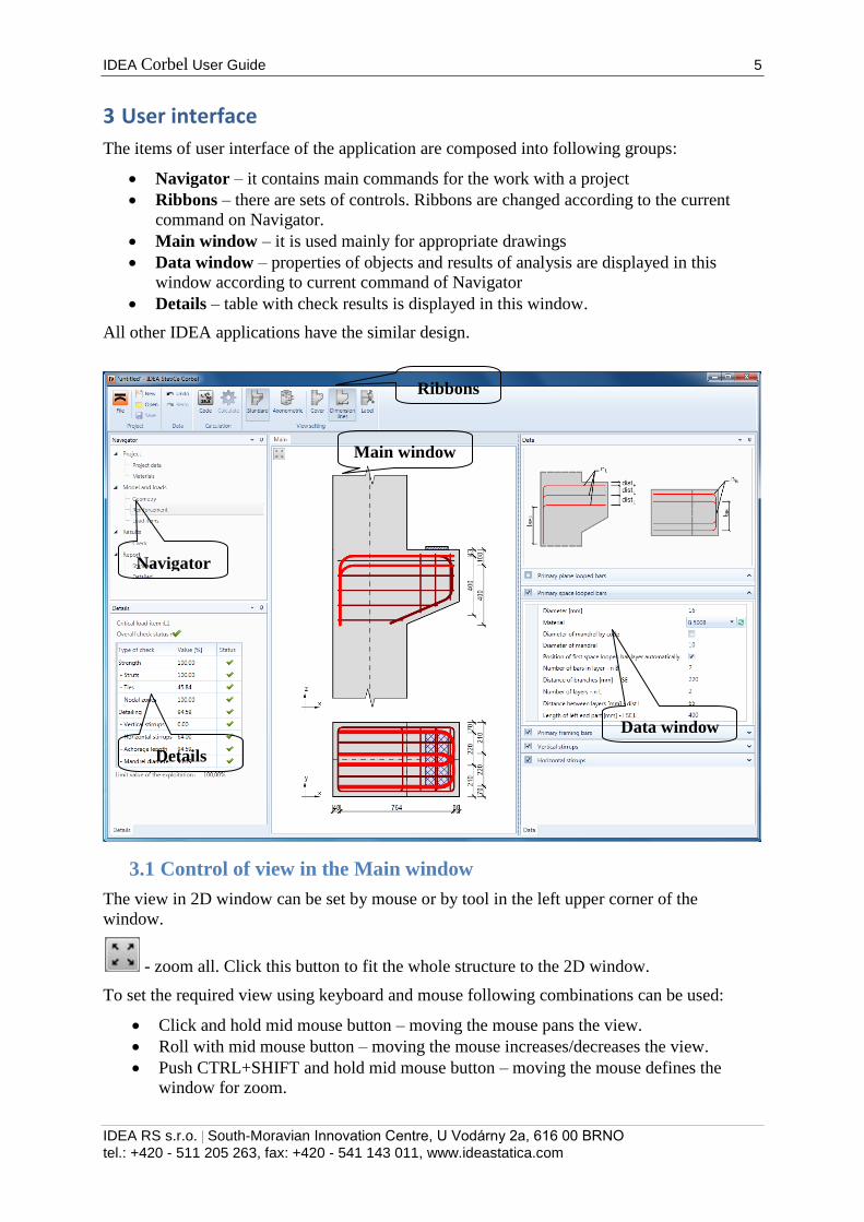
3 User interface
The items of user interface of the application are composed into following groups:
Navigator – it contains main commands for the work with a project
Ribbons – there are sets of controls. Ribbons are changed according to the current
command on Navigator.
Main window – it is used mainly for appropriate drawings
Data window – properties of objects and results of analysis are displayed in this
window according to current command of Navigator
Details – table with check results is displayed in this window.
All other IDEA applications have the similar design.
3.1 Control of view in the Main window
The view in 2D window can be set by mouse or by tool in the left upper corner of the
window.
- zoom all. Click this button to fit the whole structure to the 2D window.
To set the required view using keyboard and mouse following combinations can be used:
Click and hold mid mouse button – moving the mouse pans the view.
Roll with mid mouse button – moving the mouse increases/decreases the view.
Push CTRL+SHIFT and hold mid mouse button – moving the mouse defines the
window for zoom.
Ribbons
Main window
Data window
Navigator
Details
IDEA Corbel User Guide 6
IDEA RS s.r.o. | South-Moravian Innovation Centre, U Vodárny 2a, 616 00 BRNO
tel.: +420 - 511 205 263, fax: +420 - 541 143 011, www.ideastatica.com
Click on right mouse button over 2D window shows context menu with following commands:
Zoom all – zoom to show the whole current structure in the 2D window.
Print – start printing of the current content of 2D window on selected printer.
To bitmap – start export of the current content of 2D window to the raster graphics
file (PNG, GIF, BMP, JPEG, TIFF).
To clipboard – copy of the current content of 2D window to the Windows clipboard.
To DXF – start export of the current content of 2D window to the 2D DXF file.
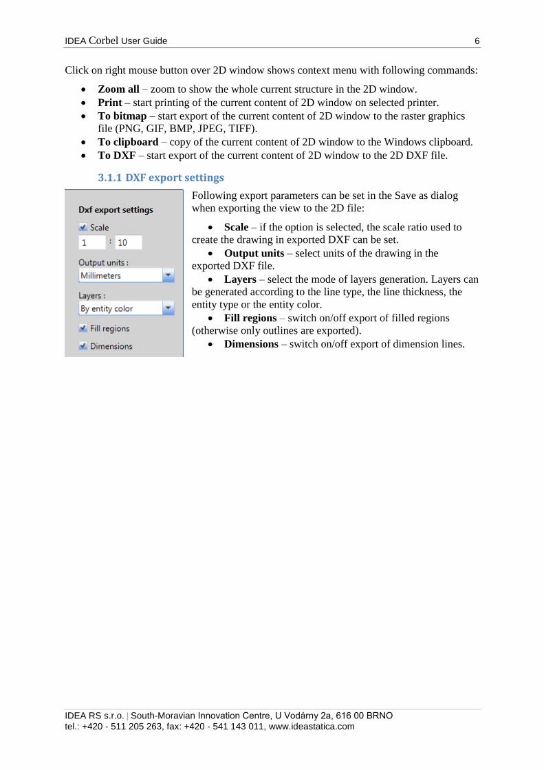
3.1.1 DXF export settings
Following export parameters can be set in the Save as dialog
when exporting the view to the 2D file:
Scale – if the option is selected, the scale ratio used to
create the drawing in exported DXF can be set.
Output units – select units of the drawing in the
exported DXF file.
Layers – select the mode of layers generation. Layers can
be generated according to the line type, the line thickness, the
entity type or the entity color.
Fill regions – switch on/off export of filled regions
(otherwise only outlines are exported).
Dimensions – switch on/off export of dimension lines.
IDEA Corbel User Guide 7
IDEA RS s.r.o. | South-Moravian Innovation Centre, U Vodárny 2a, 616 00 BRNO
tel.: +420 - 511 205 263, fax: +420 - 541 143 011, www.ideastatica.com
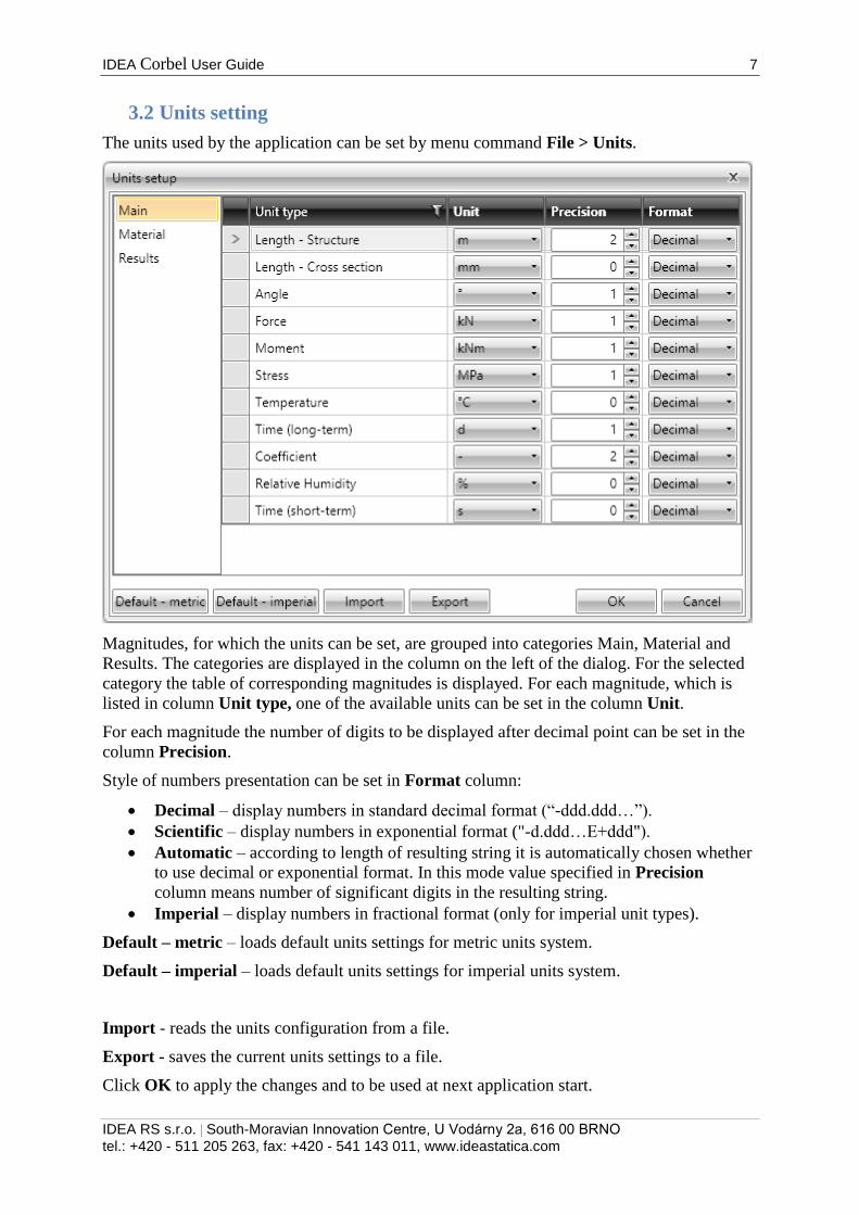
3.2 Units setting
The units used by the application can be set by menu command File > Units.
Magnitudes, for which the units can be set, are grouped into categories Main, Material and
Results. The categories are displayed in the column on the left of the dialog. For the selected
category the table of corresponding magnitudes is displayed. For each magnitude, which is
listed in column Unit type, one of the available units can be set in the column Unit.
For each magnitude the number of digits to be displayed after decimal point can be set in the
column Precision.
Style of numbers presentation can be set in Format column:
Decimal – display numbers in standard decimal format (“-ddd.ddd…”).
Scientific – display numbers in exponential format ("-d.ddd…E+ddd").
Automatic – according to length of resulting string it is automatically chosen whether
to use decimal or exponential format. In this mode value specified in Precision
column means number of significant digits in the resulting string.
Imperial – display numbers in fractional format (only for imperial unit types).
Default – metric – loads default units settings for metric units system.
Default – imperial – loads default units settings for imperial units system.
Import - reads the units configuration from a file.
Export - saves the current units settings to a file.
Click OK to apply the changes and to be used at next application start.
IDEA Corbel User Guide 8
IDEA RS s.r.o. | South-Moravian Innovation Centre, U Vodárny 2a, 616 00 BRNO
tel.: +420 - 511 205 263, fax: +420 - 541 143 011, www.ideastatica.com
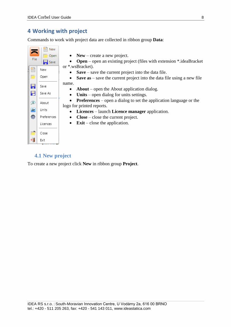
4 Working with project
Commands to work with project data are collected in ribbon group Data:
New – create a new project.
Open – open an existing project (files with extension *.ideaBracket
or *.wsBracket).
Save – save the current project into the data file.
Save as – save the current project into the data file using a new file
name.
About – open the About application dialog.
Units – open dialog for units settings.
Preferences – open a dialog to set the application language or the
logo for printed reports.
Licences – launch Licence manager application.
Close – close the current project.
Exit – close the application.
4.1 New project
To create a new project click New in ribbon group Project.
IDEA Corbel User Guide 9
IDEA RS s.r.o. | South-Moravian Innovation Centre, U Vodárny 2a, 616 00 BRNO
tel.: +420 - 511 205 263, fax: +420 - 541 143 011, www.ideastatica.com
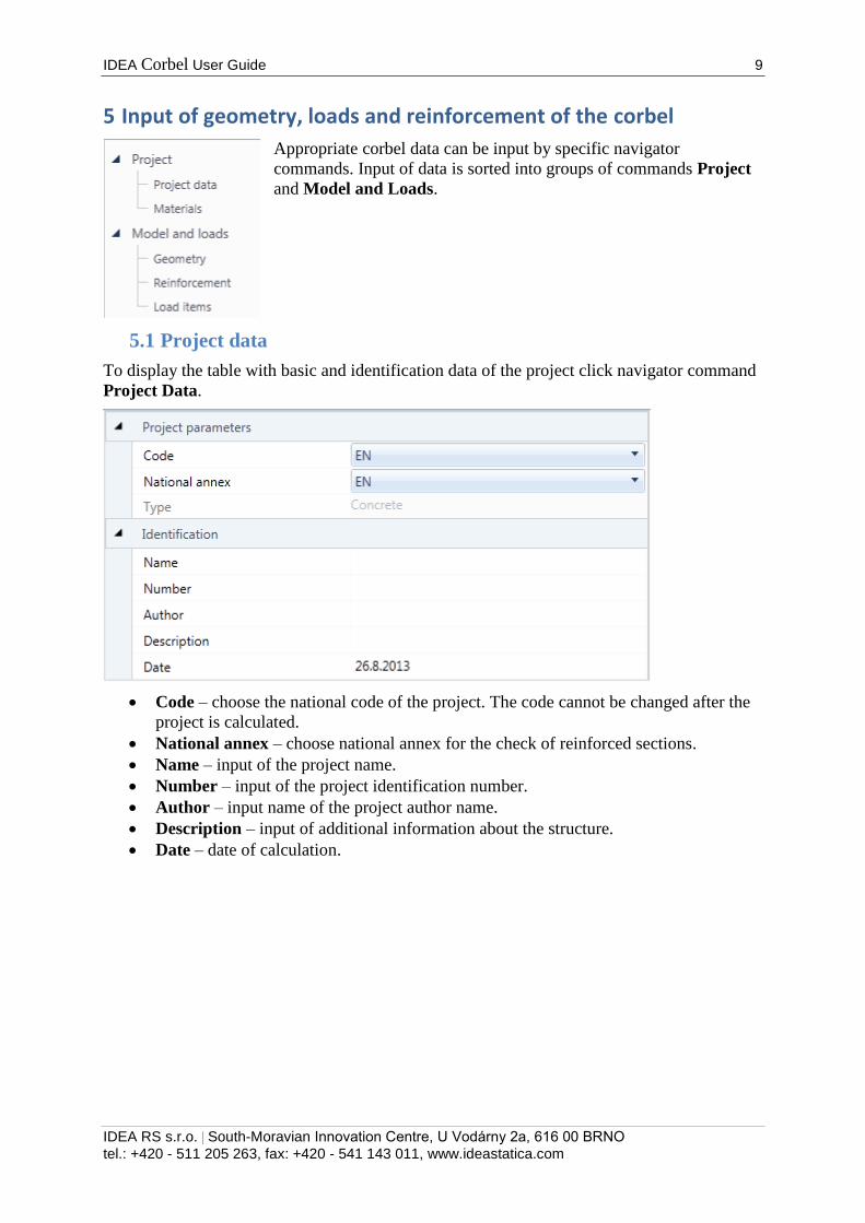
5 Input of geometry, loads and reinforcement of the corbel
Appropriate corbel data can be input by specific navigator
commands. Input of data is sorted into groups of commands Project
and Model and Loads.
5.1 Project data
To display the table with basic and identification data of the project click navigator command
Project Data.
Code – choose the national code of the project. The code cannot be changed after the
project is calculated.
National annex – choose national annex for the check of reinforced sections.
Name – input of the project name.
Number – input of the project identification number.
Author – input name of the project author name.
Description – input of additional information about the structure.
Date – date of calculation.
IDEA Corbel User Guide 10
IDEA RS s.r.o. | South-Moravian Innovation Centre, U Vodárny 2a, 616 00 BRNO
tel.: +420 - 511 205 263, fax: +420 - 541 143 011, www.ideastatica.com
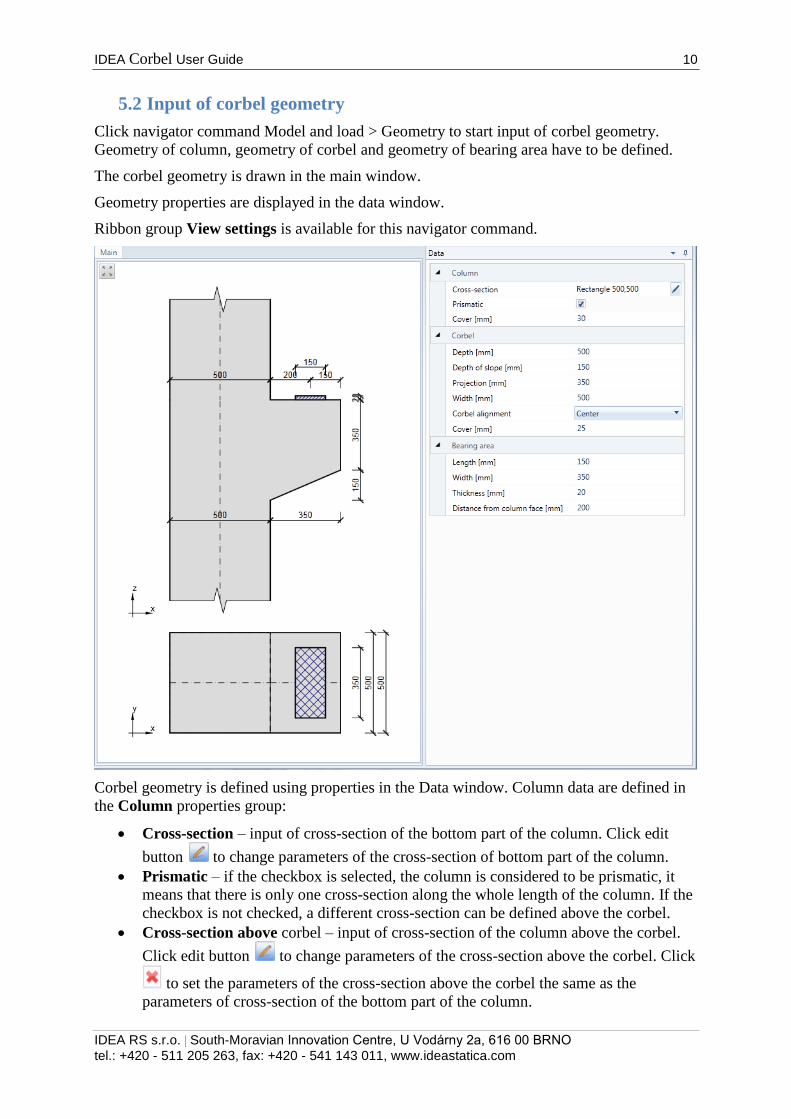
5.2 Input of corbel geometry
Click navigator command Model and load > Geometry to start input of corbel geometry.
Geometry of column, geometry of corbel and geometry of bearing area have to be defined.
The corbel geometry is drawn in the main window.
Geometry properties are displayed in the data window.
Ribbon group View settings is available for this navigator command.
Corbel geometry is defined using properties in the Data window. Column data are defined in
the Column properties group:
Cross-section – input of cross-section of the bottom part of the column. Click edit
button to change parameters of the cross-section of bottom part of the column.
Prismatic – if the checkbox is selected, the column is considered to be prismatic, it
means that there is only one cross-section along the whole length of the column. If the
checkbox is not checked, a different cross-section can be defined above the corbel.
Cross-section above corbel – input of cross-section of the column above the corbel.
Click edit button to change parameters of the cross-section above the corbel. Click
to set the parameters of the cross-section above the corbel the same as the
parameters of cross-section of the bottom part of the column.
IDEA Corbel User Guide 11
IDEA RS s.r.o. | South-Moravian Innovation Centre, U Vodárny 2a, 616 00 BRNO
tel.: +420 - 511 205 263, fax: +420 - 541 143 011, www.ideastatica.com
Column alignment – choose the alignment of cross-section above the corbel. One of
following modes can be chosen:
o Left – the cross-section above the corbel moves to align left faces of the cross-
sections.
o Right – the cross-section above the corbel moves to align right faces of the
cross-sections.
o Center – the cross-section above the corbel moves to align centroidal axes of
the cross-sections.
o Eccentricity – the cross-section above the corbel moves to position defined in
Eccentricity property.
Eccentricity – input the distance between centroidal axis of the cross-section above
the corbel and the centroidal axis of cross-section of the bottom part of column.
Cover – input thickness of concrete cover of column and corbel (except the top side of
the corbel).
Corbel parameters are defined in the Corbel properties group:
Depth – input the total height of the corbel.
Depth of sloped part – input the depth of sloped part of the corbel, measured from
the bottom edge of the corbel.
Projection – input the projection of the corbel, measured from the face of the column
under the corbel.
Width – input width of the corbel.
Corbel alignment – choose the alignment of corbel, which is narrower than the
column under the corbel. . One of following modes can be chosen (in the direction of
front view on the corbel):
o Left – the corbel moves to be aligned to the left face of the column.
o Right -– the corbel moves to be aligned to the right face of the column
o Center – the corbel moves to align the vertical axis of the corbel and the
centroidal axis of the column.
o Eccentricity - the corbel moves to position defined in Eccentricity property.
Eccentricity – – input the distance between centroidal axis of the column cross-
section and the centroidal axis of the corbel.
Cover – input thickness of concrete cover of the top side of the corbel.
Bearing area properties are defined in the Bearing area properties group:
Length – input the length of bearing area (in the direction perpendicular to the front
view on the corbel).
Width – input the width of bearing area (in the direction of the front view on the
corbel).
Thickness – input the thickness of the corbel.
Distance from column face – input the distance between centroid of bearing area and
the face of column above the corbel.
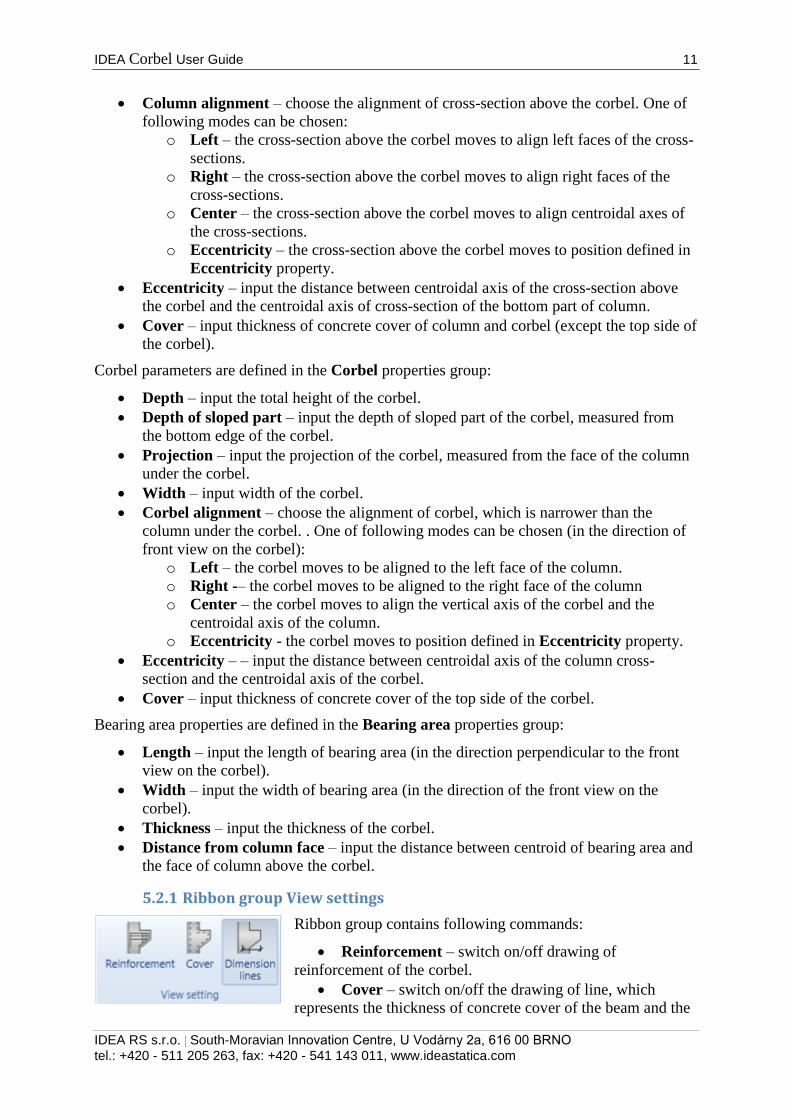
5.2.1 Ribbon group View settings
Ribbon group contains following commands:
Reinforcement – switch on/off drawing of
reinforcement of the corbel.
Cover – switch on/off the drawing of line, which
represents the thickness of concrete cover of the beam and the

IDEA Corbel User Guide 12
IDEA RS s.r.o. | South-Moravian Innovation Centre, U Vodárny 2a, 616 00 BRNO
tel.: +420 - 511 205 263, fax: +420 - 541 143 011, www.ideastatica.com
corbel.
Dimension lines – switch on/off drawing of dimension lines of the corbel geometry.
IDEA Corbel User Guide 13
IDEA RS s.r.o. | South-Moravian Innovation Centre, U Vodárny 2a, 616 00 BRNO
tel.: +420 - 511 205 263, fax: +420 - 541 143 011, www.ideastatica.com
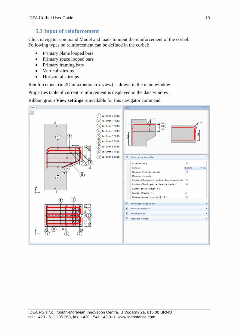
5.3 Input of reinforcement
Click navigator command Model and loads to input the reinforcement of the corbel.
Following types on reinforcement can be defined in the corbel:
Primary plane looped bars
Primary space looped bars
Primary framing bars
Vertical stirrups
Horizontal stirrups
Reinforcement (in 2D or axonometric view) is drawn in the main window.
Properties table of current reinforcement is displayed in the data window.
Ribbon group View settings is available for this navigator command.
IDEA Corbel User Guide 14
IDEA RS s.r.o. | South-Moravian Innovation Centre, U Vodárny 2a, 616 00 BRNO
tel.: +420 - 511 205 263, fax: +420 - 541 143 011, www.ideastatica.com
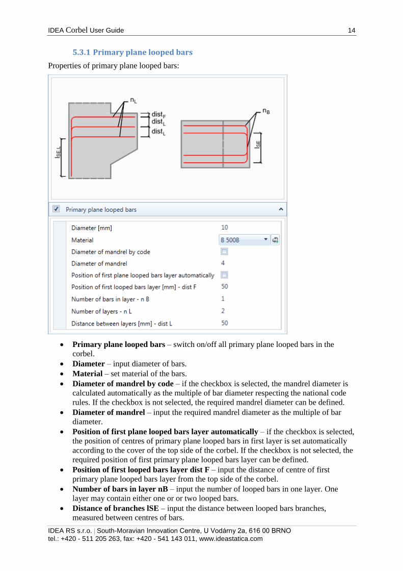
5.3.1 Primary plane looped bars
Properties of primary plane looped bars:
Primary plane looped bars – switch on/off all primary plane looped bars in the
corbel.
Diameter – input diameter of bars.
Material – set material of the bars.
Diameter of mandrel by code – if the checkbox is selected, the mandrel diameter is
calculated automatically as the multiple of bar diameter respecting the national code
rules. If the checkbox is not selected, the required mandrel diameter can be defined.
Diameter of mandrel – input the required mandrel diameter as the multiple of bar
diameter.
Position of first plane looped bars layer automatically – if the checkbox is selected,
the position of centres of primary plane looped bars in first layer is set automatically
according to the cover of the top side of the corbel. If the checkbox is not selected, the
required position of first primary plane looped bars layer can be defined.
Position of first looped bars layer dist F – input the distance of centre of first
primary plane looped bars layer from the top side of the corbel.
Number of bars in layer nB – input the number of looped bars in one layer. One
layer may contain either one or or two looped bars.
Distance of branches lSE – input the distance between looped bars branches,
measured between centres of bars.

IDEA Corbel User Guide 15
IDEA RS s.r.o. | South-Moravian Innovation Centre, U Vodárny 2a, 616 00 BRNO
tel.: +420 - 511 205 263, fax: +420 - 541 143 011, www.ideastatica.com
Number of layers nL – input the number of layers of primary plane looped bars. Each
layer may contain either one or two looped bars.
Distance between layers L – input distance between layers of primary plane looped
bars. The distance is measured between centres of bars.
IDEA Corbel User Guide 16
IDEA RS s.r.o. | South-Moravian Innovation Centre, U Vodárny 2a, 616 00 BRNO
tel.: +420 - 511 205 263, fax: +420 - 541 143 011, www.ideastatica.com
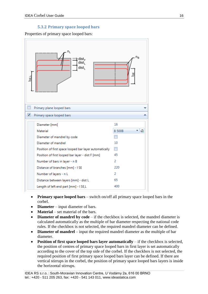
5.3.2 Primary space looped bars
Properties of primary space looped bars:
Primary space looped bars – switch on/off all primary space looped bars in the
corbel.
Diameter – input diameter of bars.
Material – set material of the bars.
Diameter of mandrel by code – if the checkbox is selected, the mandrel diameter is
calculated automatically as the multiple of bar diameter respecting the national code
rules. If the checkbox is not selected, the required mandrel diameter can be defined.
Diameter of mandrel – input the required mandrel diameter as the multiple of bar
diameter.
Position of first space looped bars layer automatically – if the checkbox is selected,
the position of centres of primary space looped bars in first layer is set automatically
according to the cover of the top side of the corbel. If the checkbox is not selected, the
required position of first primary space looped bars layer can be defined. If there are
vertical stirrups in the corbel, the position of primary space looped bars layers is inside
the horizontal stirrups.

IDEA Corbel User Guide 17
IDEA RS s.r.o. | South-Moravian Innovation Centre, U Vodárny 2a, 616 00 BRNO
tel.: +420 - 511 205 263, fax: +420 - 541 143 011, www.ideastatica.com
Position of first looped bars layer dist F – input the distance of centre of first
primary space looped bars layer from the top side of the corbel.
Number of bars in layer nB – input the number of looped bars in one layer. One
layer may contain either one or two looped bars.
Distance of branches lSE – input the distance between looped bars branches,
measured between centres of bars.
Number of layers nL – input the number of layers of primary space looped bars.
Each layer may contain either one or two looped bars.
Distance between layers L – input distance between layers of primary space looped
bars. The distance is measured between centres of bars.
Length of left end part – input the length of left vertical part of the primary space
looped bar.
IDEA Corbel User Guide 18
IDEA RS s.r.o. | South-Moravian Innovation Centre, U Vodárny 2a, 616 00 BRNO
tel.: +420 - 511 205 263, fax: +420 - 541 143 011, www.ideastatica.com
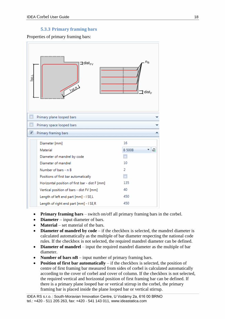
5.3.3 Primary framing bars
Properties of primary framing bars:
Primary framing bars – switch on/off all primary framing bars in the corbel.
Diameter – input diameter of bars.
Material – set material of the bars.
Diameter of mandrel by code – if the checkbox is selected, the mandrel diameter is
calculated automatically as the multiple of bar diameter respecting the national code
rules. If the checkbox is not selected, the required mandrel diameter can be defined.
Diameter of mandrel – input the required mandrel diameter as the multiple of bar
diameter.
Number of bars nB – input number of primary framing bars.
Position of first bar automatically – if the checkbox is selected, the position of
centre of first framing bar measured from sides of corbel is calculated automatically
according to the cover of corbel and cover of column. If the checkbox is not selected,
the required vertical and horizontal position of first framing bar can be defined. If
there is a primary plane looped bar or vertical stirrup in the corbel, the primary
framing bar is placed inside the plane looped bar or vertical stirrup.

IDEA Corbel User Guide 19
IDEA RS s.r.o. | South-Moravian Innovation Centre, U Vodárny 2a, 616 00 BRNO
tel.: +420 - 511 205 263, fax: +420 - 541 143 011, www.ideastatica.com
Horizontal position of first bar dist F – input the distance of centre of first framing
bar from the side of the corbel.
Vertical position of bars dist FV – input the distance of centre of the vertical part of
the primary framing bar from the top of the corbel.
Length of left end part – input the length of left vertical part of the primary framing
bar.
Length of right end part – input the length of the right sloped part of the primary
framing bar.
IDEA Corbel User Guide 20
IDEA RS s.r.o. | South-Moravian Innovation Centre, U Vodárny 2a, 616 00 BRNO
tel.: +420 - 511 205 263, fax: +420 - 541 143 011, www.ideastatica.com
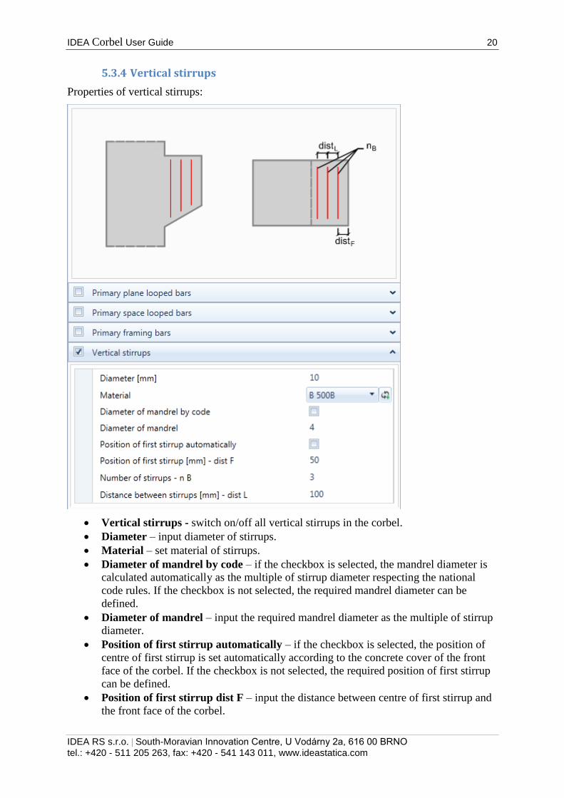
5.3.4 Vertical stirrups
Properties of vertical stirrups:
Vertical stirrups - switch on/off all vertical stirrups in the corbel.
Diameter – input diameter of stirrups.
Material – set material of stirrups.
Diameter of mandrel by code – if the checkbox is selected, the mandrel diameter is
calculated automatically as the multiple of stirrup diameter respecting the national
code rules. If the checkbox is not selected, the required mandrel diameter can be
defined.
Diameter of mandrel – input the required mandrel diameter as the multiple of stirrup
diameter.
Position of first stirrup automatically – if the checkbox is selected, the position of
centre of first stirrup is set automatically according to the concrete cover of the front
face of the corbel. If the checkbox is not selected, the required position of first stirrup
can be defined.
Position of first stirrup dist F – input the distance between centre of first stirrup and
the front face of the corbel.

IDEA Corbel User Guide 21
IDEA RS s.r.o. | South-Moravian Innovation Centre, U Vodárny 2a, 616 00 BRNO
tel.: +420 - 511 205 263, fax: +420 - 541 143 011, www.ideastatica.com
Number of stirrups – nB – input number of vertical stirrups.
Distance between stirrups – dist L – input the distance between centres of adjacent
vertical stirrups.
IDEA Corbel User Guide 22
IDEA RS s.r.o. | South-Moravian Innovation Centre, U Vodárny 2a, 616 00 BRNO
tel.: +420 - 511 205 263, fax: +420 - 541 143 011, www.ideastatica.com
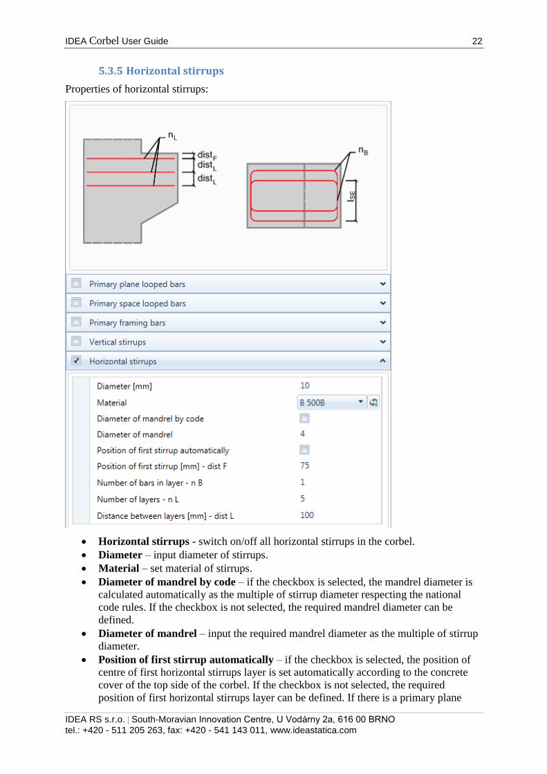
5.3.5 Horizontal stirrups
Properties of horizontal stirrups:
Horizontal stirrups - switch on/off all horizontal stirrups in the corbel.
Diameter – input diameter of stirrups.
Material – set material of stirrups.
Diameter of mandrel by code – if the checkbox is selected, the mandrel diameter is
calculated automatically as the multiple of stirrup diameter respecting the national
code rules. If the checkbox is not selected, the required mandrel diameter can be
defined.
Diameter of mandrel – input the required mandrel diameter as the multiple of stirrup
diameter.
Position of first stirrup automatically – if the checkbox is selected, the position of
centre of first horizontal stirrups layer is set automatically according to the concrete
cover of the top side of the corbel. If the checkbox is not selected, the required
position of first horizontal stirrups layer can be defined. If there is a primary plane
IDEA Corbel User Guide 23
IDEA RS s.r.o. | South-Moravian Innovation Centre, U Vodárny 2a, 616 00 BRNO
tel.: +420 - 511 205 263, fax: +420 - 541 143 011, www.ideastatica.com
looped bar in the corbel, the position of first layer of horizontal stirrups is set as
distance between layers of horizontal stirrups.
Position of first stirrup dist F – input the distance between centre of first horizontal
stirrups layer and the last layer of primary plane looped bars. If there is no primary
plane looped bar in the corbel, the distance is measured from the top side of the corbel.
Number of bars in layer – nB – input number of stirrups in one layer. One layer of
horizontal stirrups can contain either one or two stirrups.
Number of layers – nL – input number of layers of horizontal stirrups.
Distance between stirrups – dist L – input the distance between centres of adjacent
layers of horizontal stirrups.
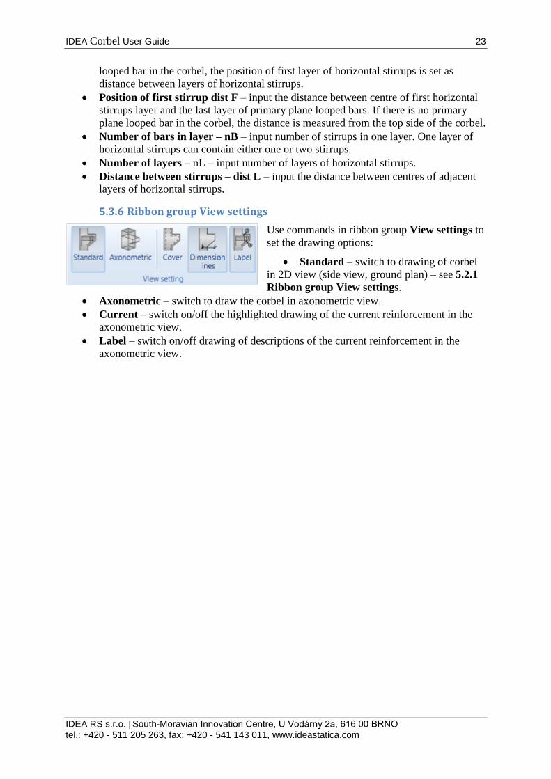
5.3.6 Ribbon group View settings
Use commands in ribbon group View settings to
set the drawing options:
Standard – switch to drawing of corbel
in 2D view (side view, ground plan) – see 5.2.1
Ribbon group View settings.
Axonometric – switch to draw the corbel in axonometric view.
Current – switch on/off the highlighted drawing of the current reinforcement in the
axonometric view.
Label – switch on/off drawing of descriptions of the current reinforcement in the
axonometric view.
IDEA Corbel User Guide 24
IDEA RS s.r.o. | South-Moravian Innovation Centre, U Vodárny 2a, 616 00 BRNO
tel.: +420 - 511 205 263, fax: +420 - 541 143 011, www.ideastatica.com
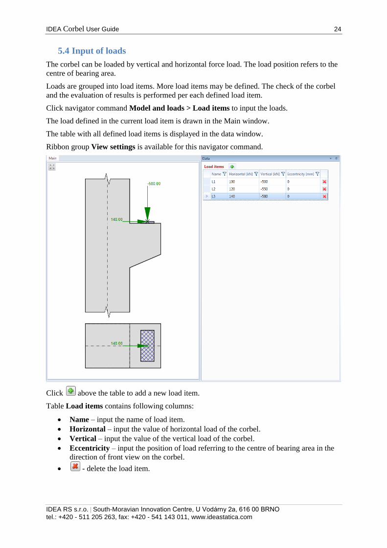
5.4 Input of loads
The corbel can be loaded by vertical and horizontal force load. The load position refers to the
centre of bearing area.
Loads are grouped into load items. More load items may be defined. The check of the corbel
and the evaluation of results is performed per each defined load item.
Click navigator command Model and loads > Load items to input the loads.
The load defined in the current load item is drawn in the Main window.
The table with all defined load items is displayed in the data window.
Ribbon group View settings is available for this navigator command.
Click above the table to add a new load item.
Table Load items contains following columns:
Name – input the name of load item.
Horizontal – input the value of horizontal load of the corbel.
Vertical – input the value of the vertical load of the corbel.
Eccentricity – input the position of load referring to the centre of bearing area in the
direction of front view on the corbel.
- delete the load item.

IDEA Corbel User Guide 25
IDEA RS s.r.o. | South-Moravian Innovation Centre, U Vodárny 2a, 616 00 BRNO
tel.: +420 - 511 205 263, fax: +420 - 541 143 011, www.ideastatica.com
5.4.1 Ribbon group View settings
Use commands in ribbon group View settings to set the drawing options:
Reinforcement – switch on/off the drawing of defined reinforcement.
IDEA Corbel User Guide 26
IDEA RS s.r.o. | South-Moravian Innovation Centre, U Vodárny 2a, 616 00 BRNO
tel.: +420 - 511 205 263, fax: +420 - 541 143 011, www.ideastatica.com
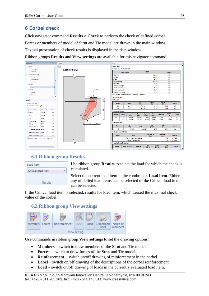
6 Corbel check
Click navigator command Results > Check to perform the check of defined corbel.
Forces or members of model of Strut and Tie model are drawn in the main window.
Textual presentation of check results is displayed in the data window.
Ribbon groups Results and View settings are available for this navigator command.
6.1 Ribbon group Results
Use ribbon group Results to select the load for which the check is
calculated.
Select the current load item in the combo box Load item. Either
any of defied load items can be selected or the Critical load item
can be selected.
If the Critical load item is selected, results for load item, which caused the maximal check
value of the corbel
6.2 Ribbon group View settings
Use commands in ribbon group View settings to set the drawing options:
Members – switch to draw members of the Strut and Tie model.
Forces – switch to draw forces of the Strut and Tie model.
Reinforcement – switch on/off drawing of reinforcement in the corbel.
Label – switch on/off drawing of the descriptions of the corbel reinforcement.
Load – switch on/off drawing of loads in the currently evaluated load item.

IDEA Corbel User Guide 27
IDEA RS s.r.o. | South-Moravian Innovation Centre, U Vodárny 2a, 616 00 BRNO
tel.: +420 - 511 205 263, fax: +420 - 541 143 011, www.ideastatica.com
Dimension lines– switch on/off drawing of dimension lines of the Strut and Tie model
members.
Name of members – switch on/off drawing of names of the Strut and Tie model
members.
IDEA Corbel User Guide 28
IDEA RS s.r.o. | South-Moravian Innovation Centre, U Vodárny 2a, 616 00 BRNO
tel.: +420 - 511 205 263, fax: +420 - 541 143 011, www.ideastatica.com
7 Report
Input data, calculation results, check data and check results can be
printed in report. Report can contain texts, tables and pictures. Structure
of report is fixed, it is only possible to set, which tables and which
pictures should be generated.
Use commands in navigator group Report to generate reports for the whole structure.
Use commands in ribbon group Report view to print and export the report
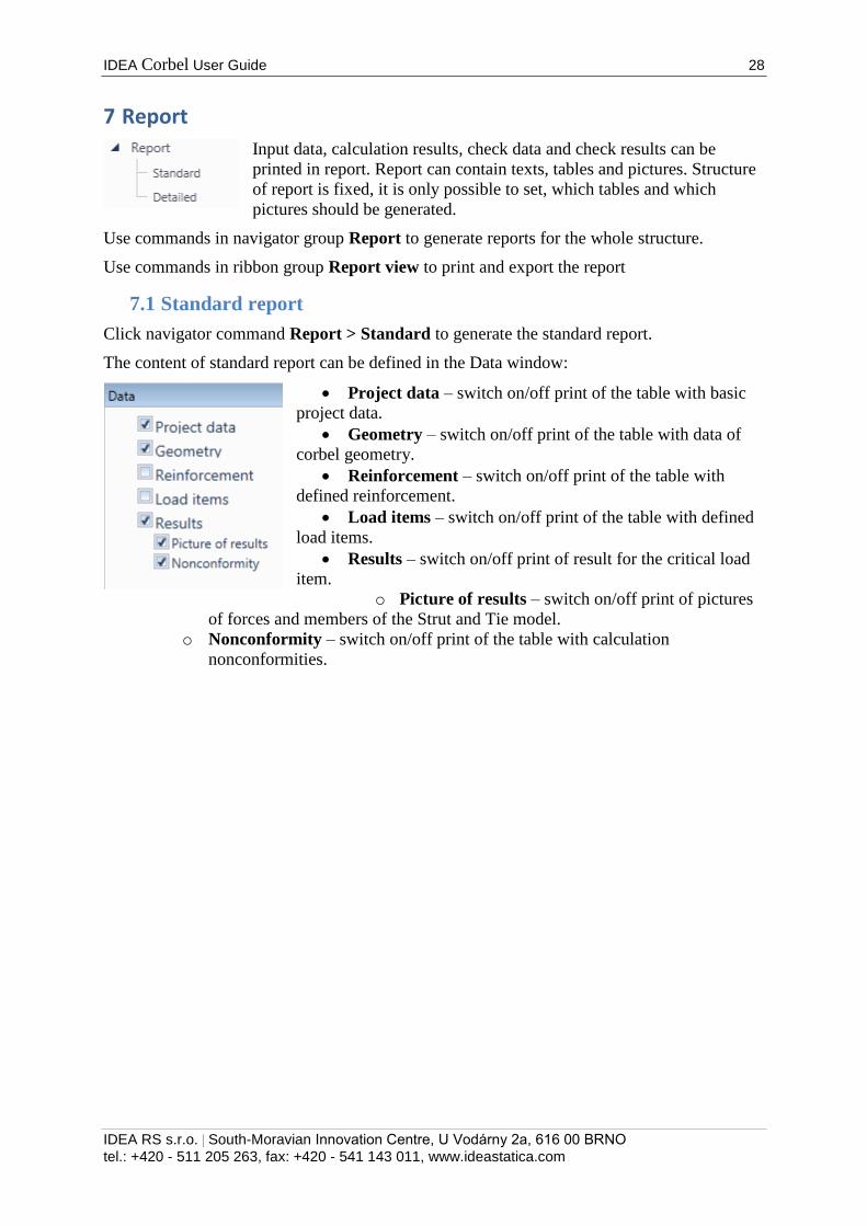
7.1 Standard report
Click navigator command Report > Standard to generate the standard report.
The content of standard report can be defined in the Data window:
Project data – switch on/off print of the table with basic
project data.
Geometry – switch on/off print of the table with data of
corbel geometry.
Reinforcement – switch on/off print of the table with
defined reinforcement.
Load items – switch on/off print of the table with defined
load items.
Results – switch on/off print of result for the critical load
item.
o Picture of results – switch on/off print of pictures
of forces and members of the Strut and Tie model.
o Nonconformity – switch on/off print of the table with calculation
nonconformities.
IDEA Corbel User Guide 29
IDEA RS s.r.o. | South-Moravian Innovation Centre, U Vodárny 2a, 616 00 BRNO
tel.: +420 - 511 205 263, fax: +420 - 541 143 011, www.ideastatica.com
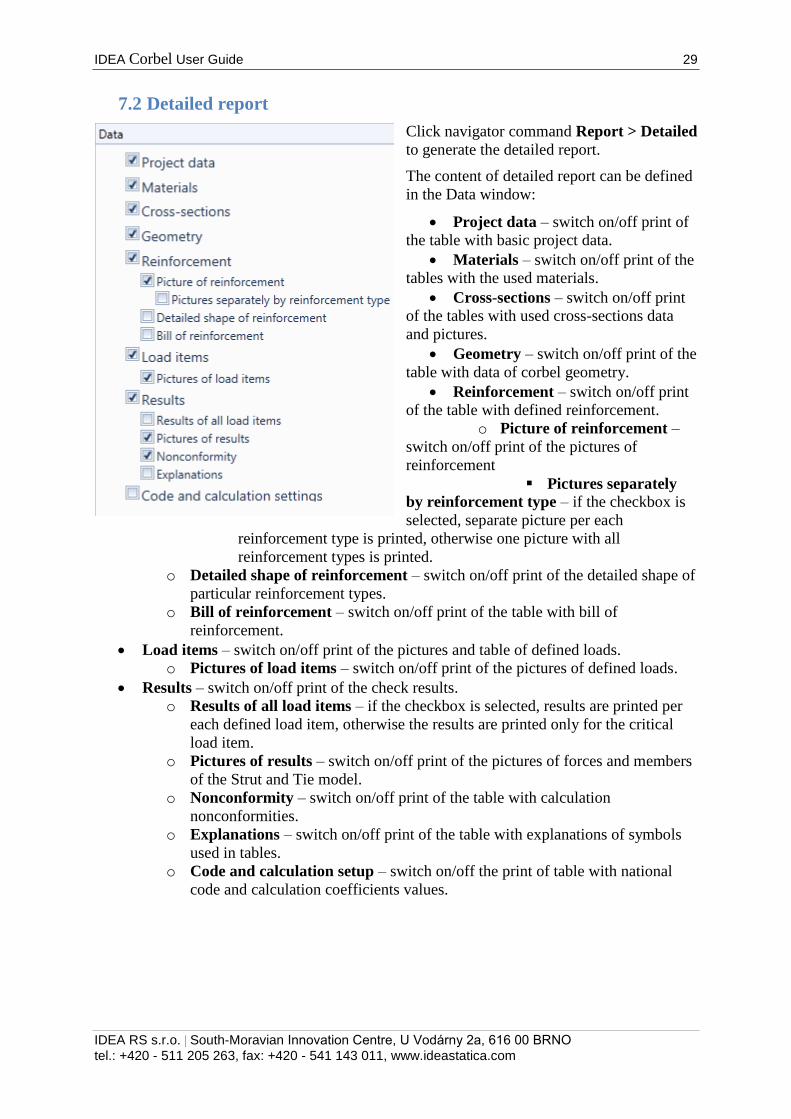
7.2 Detailed report
Click navigator command Report > Detailed
to generate the detailed report.
The content of detailed report can be defined
in the Data window:
Project data – switch on/off print of
the table with basic project data.
Materials – switch on/off print of the
tables with the used materials.
Cross-sections – switch on/off print
of the tables with used cross-sections data
and pictures.
Geometry – switch on/off print of the
table with data of corbel geometry.
Reinforcement – switch on/off print
of the table with defined reinforcement.
o Picture of reinforcement –
switch on/off print of the pictures of
reinforcement
Pictures separately
by reinforcement type – if the checkbox is
selected, separate picture per each
reinforcement type is printed, otherwise one picture with all
reinforcement types is printed.
o Detailed shape of reinforcement – switch on/off print of the detailed shape of
particular reinforcement types.
o Bill of reinforcement – switch on/off print of the table with bill of
reinforcement.
Load items – switch on/off print of the pictures and table of defined loads.
o Pictures of load items – switch on/off print of the pictures of defined loads.
Results – switch on/off print of the check results.
o Results of all load items – if the checkbox is selected, results are printed per
each defined load item, otherwise the results are printed only for the critical
load item.
o Pictures of results – switch on/off print of the pictures of forces and members
of the Strut and Tie model.
o Nonconformity – switch on/off print of the table with calculation
nonconformities.
o Explanations – switch on/off print of the table with explanations of symbols
used in tables.
o Code and calculation setup – switch on/off the print of table with national
code and calculation coefficients values.

IDEA Corbel User Guide 30
IDEA RS s.r.o. | South-Moravian Innovation Centre, U Vodárny 2a, 616 00 BRNO
tel.: +420 - 511 205 263, fax: +420 - 541 143 011, www.ideastatica.com
7.3 Ribbon group Report view
To print and export the report use commands in ribbon group
Report view.
Refresh – regenerate the report according to the current
setting of report content
Print –print of the report to the selected print device
Preview – display print preview of the report
Save as – save the report to the file of HTML, MHT (web archive including pictures)
or TXT format.