idea statica connection - eiseko...idea statica connection theoretical background 8 the influence of...
TRANSCRIPT

www.ideastatica.com
IDEA StatiCa Connection
Theoretical background
June 2017

www.ideastatica.com
Content
1 Introduction .......................................................................................................................................... 4
2 CBFEM components ............................................................................................................................. 5
2.1 Material model .............................................................................................................................. 6
2.2 Plate model and mesh convergence ............................................................................................. 8
2.2.1 Plate model ............................................................................................................................ 8
2.2.2 Mesh convergence................................................................................................................. 8
2.3 Contacts ...................................................................................................................................... 10
2.4 Welds .......................................................................................................................................... 11
2.4.1 Direct connection of plates.................................................................................................. 11
2.4.2 Plastic welds ........................................................................................................................ 12
2.5 Bolts ............................................................................................................................................ 13
2.6 Preloaded bolts ........................................................................................................................... 15
2.7 Anchor bolts ................................................................................................................................ 15
2.8 Concrete block ............................................................................................................................ 16
2.8.1 Design model ....................................................................................................................... 16
2.8.2 Deformation stiffness .......................................................................................................... 16
3 Analysis ............................................................................................................................................... 17
3.1 Analysis model ............................................................................................................................ 17
3.2 Bearing member and supports ................................................................................................... 17
3.3 Equilibrium in node ..................................................................................................................... 19
3.4 Loads ........................................................................................................................................... 20
3.4.1 Import loads from FEA programs ........................................................................................ 24
3.5 Strength analysis ......................................................................................................................... 24
3.6 Stiffness analysis ......................................................................................................................... 25
3.7 Member capacity design ............................................................................................................. 27
3.8 Design joint resistance ................................................................................................................ 28
3.9 Stability analysis .......................................................................................................................... 29
3.10 Deformation capacity ................................................................................................................ 30
4 Check of components according to Eurocode .................................................................................... 31
4.1 Plates ........................................................................................................................................... 31
4.2 Welds .......................................................................................................................................... 31
4.2.1 Fillet welds ........................................................................................................................... 31
4.2.2 Butt welds ............................................................................................................................ 32
4.3 Bolts ............................................................................................................................................ 32
4.4 Preloaded bolts ........................................................................................................................... 34
4.5 Anchors ....................................................................................................................................... 34
www.ideastatica.com
4.6 Concrete block ............................................................................................................................ 36
4.6.1 Mesh sensitivity ................................................................................................................... 37
4.7 Shear in concrete block ............................................................................................................... 39
4.8 Member capacity design ............................................................................................................. 39
4.9 Stability analysis .......................................................................................................................... 39
4.10 Deformation capacity ................................................................................................................ 41
5 Check of components according to AISC ............................................................................................ 43
5.1 Plates ........................................................................................................................................... 43
5.2 Welds .......................................................................................................................................... 43
5.2.1 Fillet welds ........................................................................................................................... 43
5.2.2 CJP groove welds ................................................................................................................. 45
5.3 Bolts ............................................................................................................................................ 45
5.3.1 Tensile and shear strength of bolts ..................................................................................... 45
5.3.2 Combined Tension and shear in bearing type connection .................................................. 45
5.3.3 Bearing strength in bolt holes ............................................................................................. 45
5.4 Preloaded bolts ........................................................................................................................... 46
5.5 Concrete design bearing strength in compression ..................................................................... 46
5.6 Anchors ....................................................................................................................................... 47
5.6.1 Concrete breakout strength in tension ............................................................................... 47
5.6.2 Concrete breakout strength of anchor in shear .................................................................. 47
5.7 Member capacity design ............................................................................................................. 48
6 Check of components according to CISC ............................................................................................ 49
6.1 Welds .......................................................................................................................................... 49
6.1.1 Fillet welds ........................................................................................................................... 49
6.1.2 CJP groove welds ................................................................................................................. 49
6.2 Bolts ............................................................................................................................................ 49
6.2.1 Tensile strength of bolts ...................................................................................................... 49
6.2.2 Shear strength of bolts ........................................................................................................ 50
6.2.3 Combined tension and shear in bearing type connection ................................................... 50
6.2.4 Bearing strength in bolt holes ............................................................................................. 50
6.2.5 Hole tear-out of a bolt ......................................................................................................... 50
6.2.6 Bolts in slip-critical connections .......................................................................................... 51
6.3 Member capacity design ............................................................................................................. 51
7 References .......................................................................................................................................... 52
IDEA StatiCa Connection Theoretical background 4
www.ideastatica.com
1 Introduction
Bar members are preferred by engineers when designing steel structures. However, there are many locations on the structure where the theory of members is not valid, e.g., welded joints, bolted connections, footing, holes in walls, the tapering height of cross-section and point loads. The structural analysis in such locations is difficult and it requires special attention. The behavior is non-linear and the nonlinearities must be respected, e.g., yielding of the material of plates, contact between end plates or base plate and concrete block, one-sided actions of bolts and anchors, welds. Design codes, e.g. EN1993-1-8, and also technical literature offer engineering solution methods. Their general feature is derivation for typical structural shapes and simple loadings. The method of components is used very often.
Component method
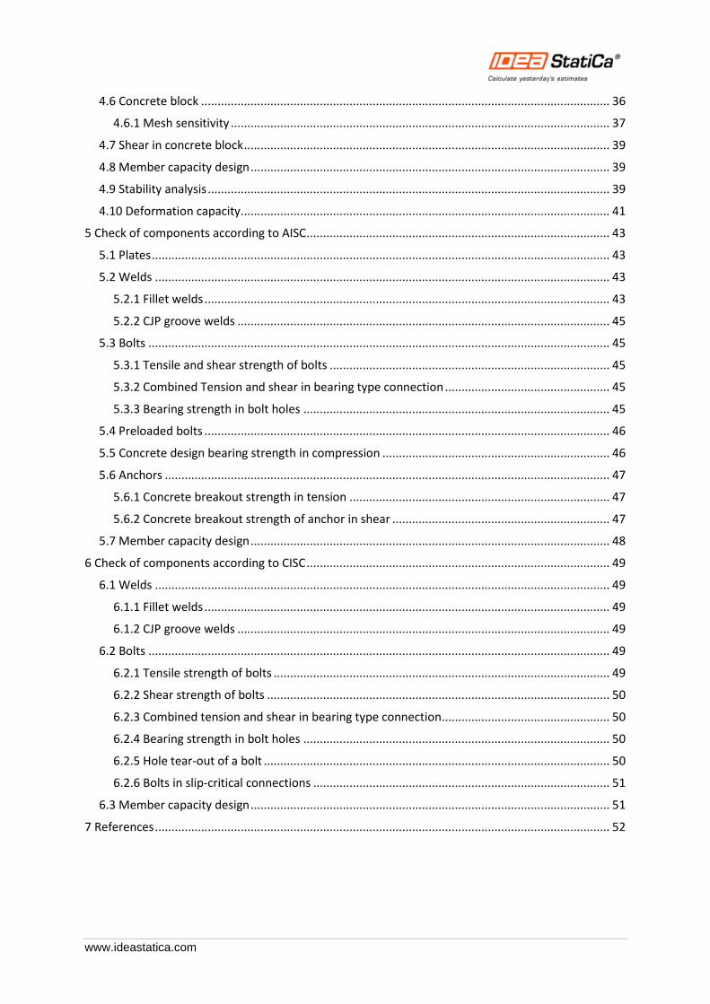
Component method (CM) solves the joint as a system of interconnected items – components. The corresponding model is built per each joint type to be able to determine forces and stresses in each component – see the following picture.
The components of a joint with bolted end plates modeled by springs
Each component is checked separately using corresponding formulas. As the proper model must be created for each joint type, the method usage has limits when solving joints of general shapes and general loads.
IDEA StatiCa together with a project team of Department of Steel and Timber Structures of Faculty of Civil Engineering in Prague and Institute of Metal and Timber Structures of Faculty of Civil Engineering of Brno University of Technology developed a new method for advanced design of steel structural joints.
The new Component Based Finite Element Model (CBFEM) method is:
• General enough to be usable for most of joints, footings and details in engineering practice.
• Simple and fast enough in daily practice to provide results in a time comparable to current methods and tools.
• Comprehensive enough to provide structural engineer clear information about joint behavior, stress, strain and reserves of individual components and about overall safety and reliability.
The CBFEM method is based on the idea that the most of the verified and very useful parts of CM should be kept. The weak point of CM – its generality when analyzing stresses of individual components – was replaced by modeling and analysis using Finite Element Method (FEM).
IDEA StatiCa Connection Theoretical background 5
www.ideastatica.com
2 CBFEM components
FEM is a general method commonly used for structural analysis. Usage of FEM for modeling of joints of any shapes seems to be ideal (Virdi, 1999). The elastic-plastic analysis is required, as the steel ordinarily yields in the structure. In fact, the results of the linear analysis are useless for joint design.
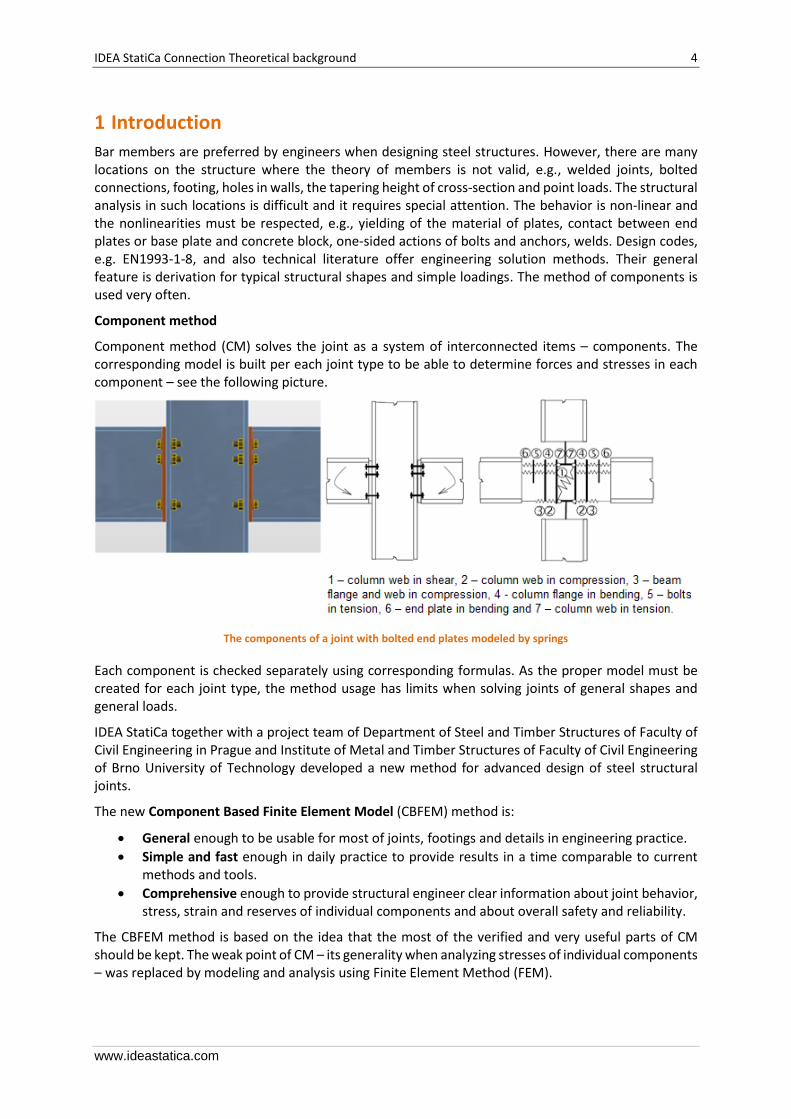
FEM models are used for research purposes of joint behavior, which usually apply spatial elements and measured values of material properties.
FEM model of a joint for research. It uses spatial 3D elements for both plates and bolts
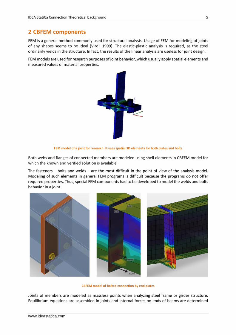
Both webs and flanges of connected members are modeled using shell elements in CBFEM model for which the known and verified solution is available.
The fasteners – bolts and welds – are the most difficult in the point of view of the analysis model. Modeling of such elements in general FEM programs is difficult because the programs do not offer required properties. Thus, special FEM components had to be developed to model the welds and bolts behavior in a joint.
CBFEM model of bolted connection by end plates
Joints of members are modeled as massless points when analyzing steel frame or girder structure. Equilibrium equations are assembled in joints and internal forces on ends of beams are determined
IDEA StatiCa Connection Theoretical background 6
www.ideastatica.com
after solving the whole structure. In fact, the joint is loaded by those forces. The resultant of forces from all members in the joint is zero – the whole joint is in equilibrium.
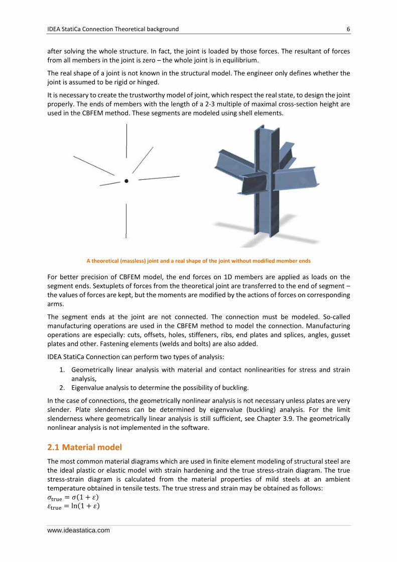
The real shape of a joint is not known in the structural model. The engineer only defines whether the joint is assumed to be rigid or hinged.
It is necessary to create the trustworthy model of joint, which respect the real state, to design the joint properly. The ends of members with the length of a 2-3 multiple of maximal cross-section height are used in the CBFEM method. These segments are modeled using shell elements.
A theoretical (massless) joint and a real shape of the joint without modified member ends
For better precision of CBFEM model, the end forces on 1D members are applied as loads on the segment ends. Sextuplets of forces from the theoretical joint are transferred to the end of segment – the values of forces are kept, but the moments are modified by the actions of forces on corresponding arms.
The segment ends at the joint are not connected. The connection must be modeled. So-called manufacturing operations are used in the CBFEM method to model the connection. Manufacturing operations are especially: cuts, offsets, holes, stiffeners, ribs, end plates and splices, angles, gusset plates and other. Fastening elements (welds and bolts) are also added.
IDEA StatiCa Connection can perform two types of analysis:
1. Geometrically linear analysis with material and contact nonlinearities for stress and strain analysis,
2. Eigenvalue analysis to determine the possibility of buckling.
In the case of connections, the geometrically nonlinear analysis is not necessary unless plates are very slender. Plate slenderness can be determined by eigenvalue (buckling) analysis. For the limit slenderness where geometrically linear analysis is still sufficient, see Chapter 3.9. The geometrically nonlinear analysis is not implemented in the software.
2.1 Material model
The most common material diagrams which are used in finite element modeling of structural steel are the ideal plastic or elastic model with strain hardening and the true stress-strain diagram. The true stress-strain diagram is calculated from the material properties of mild steels at an ambient temperature obtained in tensile tests. The true stress and strain may be obtained as follows: 𝜎true = 𝜎(1 + 휀) 휀true = ln(1 + 휀)
IDEA StatiCa Connection Theoretical background 7
www.ideastatica.com
where 𝜎true is true stress, 휀true true strain, 𝜎 engineering stress and 휀 engineering strain. The plates in IDEA StatiCa Connection are modeled with elastic-plastic material with a nominal yielding plateau slope according to EN1993-1-5, Par. C.6, (2). The material behavior is based on von Mises yield criterion. It is assumed to be elastic before reaching the yield strength, 𝑓y.
The ultimate limit state criterion for regions not susceptible to buckling is reaching the limiting value of the principal membrane strain. The value of 5% is recommended (e.g. EN1993-1-5, App. C, Par. C.8, Note 1).
Material diagrams of steel in numerical models
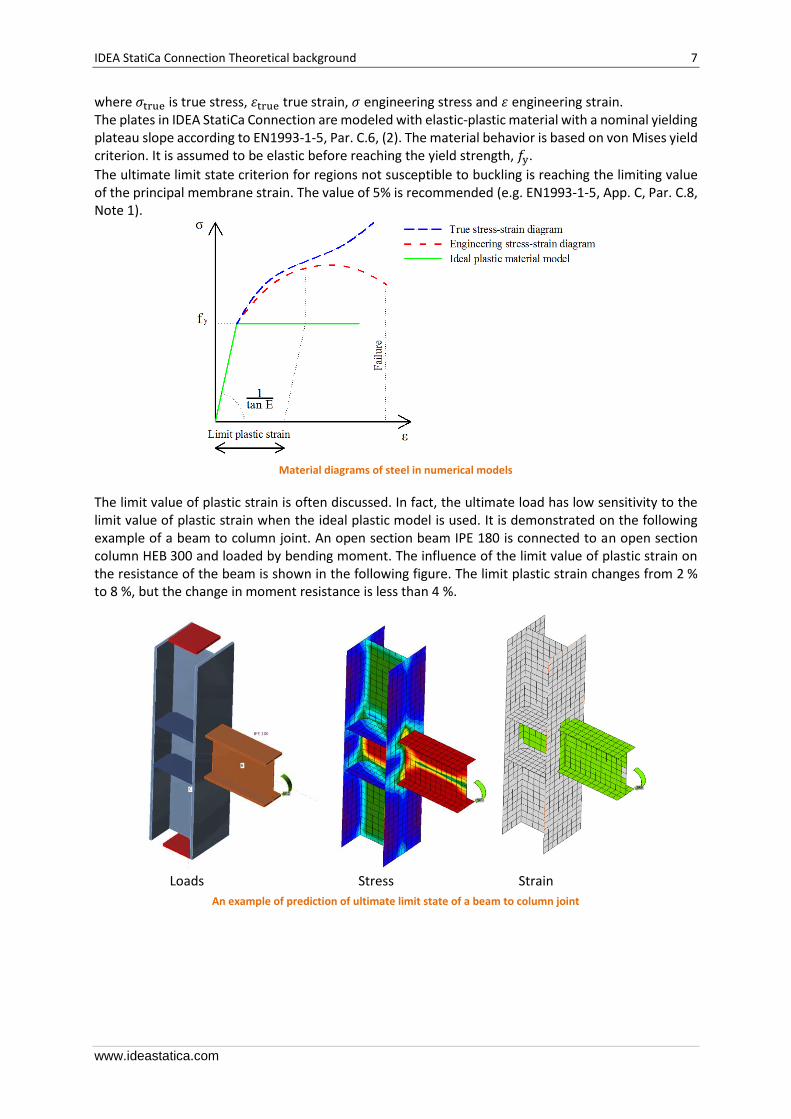
The limit value of plastic strain is often discussed. In fact, the ultimate load has low sensitivity to the limit value of plastic strain when the ideal plastic model is used. It is demonstrated on the following example of a beam to column joint. An open section beam IPE 180 is connected to an open section column HEB 300 and loaded by bending moment. The influence of the limit value of plastic strain on the resistance of the beam is shown in the following figure. The limit plastic strain changes from 2 % to 8 %, but the change in moment resistance is less than 4 %.
Loads Stress Strain
An example of prediction of ultimate limit state of a beam to column joint

IDEA StatiCa Connection Theoretical background 8
www.ideastatica.com
The influence of the limit value of plastic strain on the moment resistance
2.2 Plate model and mesh convergence
2.2.1 Plate model
Shell elements are recommended for modeling of plates in FEA of structural connection. 4-node quadrangle shell elements with nodes at its corners are applied. Six degrees of freedom are considered in each node: 3 translations (ux, uy, uz) and 3 rotations (φx, φy, φz). Deformations of the element are divided into the membrane and the flexural components.
The formulation of the membrane behavior is based on the work by Ibrahimbegovic (1990). Rotations perpendicular to the plane of the element are considered. Complete 3D formulation of the element is provided. The out-of-plane shear deformations are considered in the formulation of the flexural behavior of an element based on Mindlin hypothesis. The MITC4 elements are applied, see Dvorkin (1984). The shell is divided into five integration points along the height of the plate and plastic behavior is analyzed in each point. It is called Gauss–Lobatto integration. The nonlinear elastic-plastic stage of material is analyzed in each layer based on the known strains.
2.2.2 Mesh convergence
There are some criteria for the mesh generation in the connection model. The connection check should be independent of the element size. Mesh generation on a separate plate is problem-free. The attention should be paid to complex geometries such as stiffened panels, T-stubs and base plates. The sensitivity analysis considering mesh discretization should be performed for complicated geometries.
All plates of a beam cross-section have a common division into elements. The size of generated finite elements is limited. The minimal element size is set to 10 mm and the maximal element size to 50 mm. Meshes on flanges and webs are independent of each other. The default number of finite elements is set to 8 elements per cross-section height as shown in the following figure. The user can modify the default values in Code setup.
The mesh on a beam with constraints between the web and the flange plate
The mesh of the end plates is separate and independent of other connection parts. Default finite element size is set to 16 elements per cross-section height as shown in the figure.
39.2539.65
40.4 40.8
35
37
39
41
43
0 1 2 3 4 5 6 7 8 9
Res
ista
nce
[kN
m]
Plastic strain [%]
CBFEM
CM
IDEA StatiCa Connection Theoretical background 9
www.ideastatica.com
The mesh on an end plate with 7 elements along its width
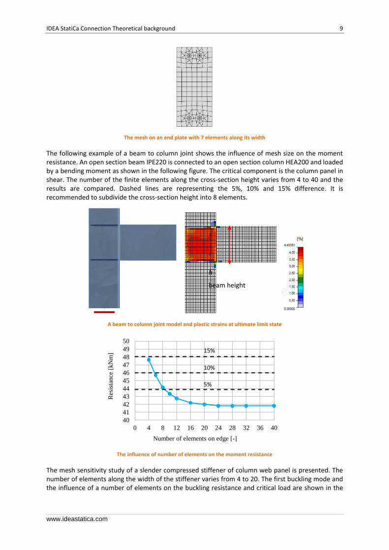
The following example of a beam to column joint shows the influence of mesh size on the moment resistance. An open section beam IPE220 is connected to an open section column HEA200 and loaded by a bending moment as shown in the following figure. The critical component is the column panel in shear. The number of the finite elements along the cross-section height varies from 4 to 40 and the results are compared. Dashed lines are representing the 5%, 10% and 15% difference. It is recommended to subdivide the cross-section height into 8 elements.
A beam to column joint model and plastic strains at ultimate limit state
The influence of number of elements on the moment resistance
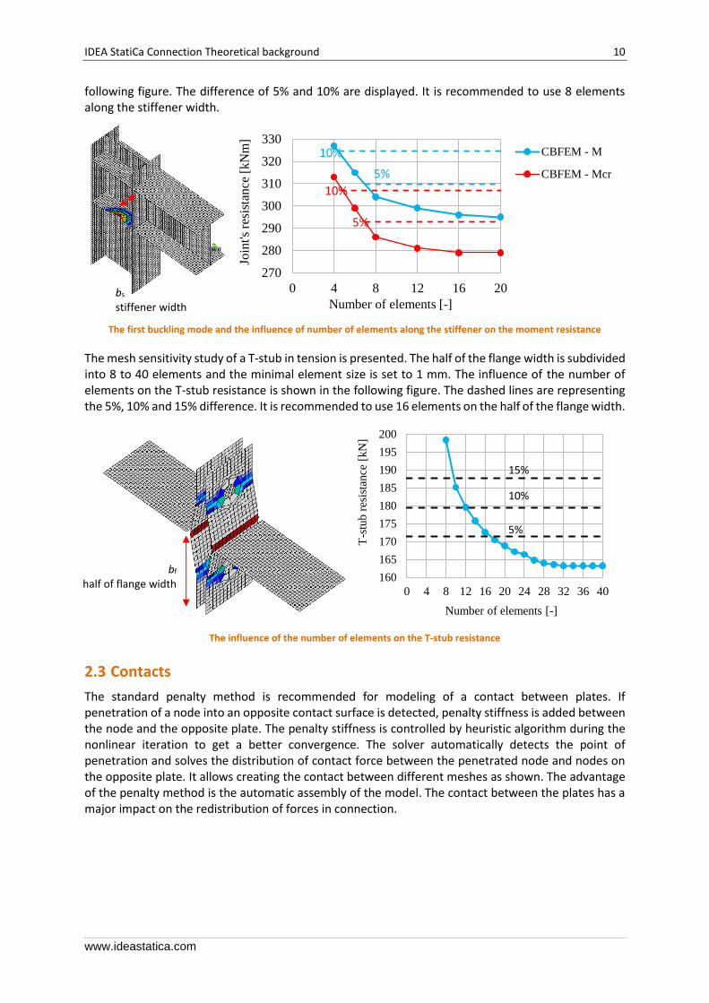
The mesh sensitivity study of a slender compressed stiffener of column web panel is presented. The number of elements along the width of the stiffener varies from 4 to 20. The first buckling mode and the influence of a number of elements on the buckling resistance and critical load are shown in the
40
41
42
43
44
45
46
47
48
49
50
0 4 8 12 16 20 24 28 32 36 40
Res
ista
nce
[kN
m]
Number of elements on edge [-]
5%
10%
15%
h
beam height
IDEA StatiCa Connection Theoretical background 10
www.ideastatica.com
following figure. The difference of 5% and 10% are displayed. It is recommended to use 8 elements along the stiffener width.
The first buckling mode and the influence of number of elements along the stiffener on the moment resistance
The mesh sensitivity study of a T-stub in tension is presented. The half of the flange width is subdivided into 8 to 40 elements and the minimal element size is set to 1 mm. The influence of the number of elements on the T-stub resistance is shown in the following figure. The dashed lines are representing the 5%, 10% and 15% difference. It is recommended to use 16 elements on the half of the flange width.
The influence of the number of elements on the T-stub resistance
2.3 Contacts
The standard penalty method is recommended for modeling of a contact between plates. If penetration of a node into an opposite contact surface is detected, penalty stiffness is added between the node and the opposite plate. The penalty stiffness is controlled by heuristic algorithm during the nonlinear iteration to get a better convergence. The solver automatically detects the point of penetration and solves the distribution of contact force between the penetrated node and nodes on the opposite plate. It allows creating the contact between different meshes as shown. The advantage of the penalty method is the automatic assembly of the model. The contact between the plates has a major impact on the redistribution of forces in connection.
270
280
290
300
310
320
330
0 4 8 12 16 20
Join
t's r
esis
tan
ce[k
Nm
]
Number of elements [-]
CBFEM - M
CBFEM - Mcr
160
165
170
175
180
185
190
195
200
0 4 8 12 16 20 24 28 32 36 40
T-s
tub
res
ista
nce
[kN
]
Number of elements [-]
15%
10%
5%
bs stiffener width
bf half of flange width
5%
10%
5%
10%
IDEA StatiCa Connection Theoretical background 11
www.ideastatica.com
An example of separation of plates in contact between the web and flanges of two overlapped Z sections purlins
2.4 Welds
There exist several options how to treat welds in numerical models. The large deformations make the mechanical analysis more complex and it is possible to use different mesh descriptions, different kinetic and kinematic variables and constitutive models. The different types of geometric 2D and 3D models and thereby finite elements with their applicability for different accuracy levels are generally used. Most often used material model is the common rate-independent plasticity model based on von Mises yield criterion. Two approaches which are used for welds are described.
2.4.1 Direct connection of plates
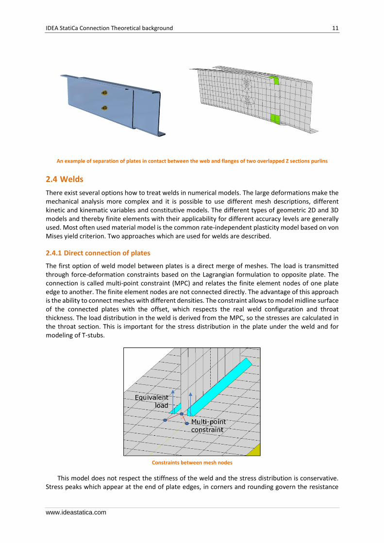
The first option of weld model between plates is a direct merge of meshes. The load is transmitted through force-deformation constraints based on the Lagrangian formulation to opposite plate. The connection is called multi-point constraint (MPC) and relates the finite element nodes of one plate edge to another. The finite element nodes are not connected directly. The advantage of this approach is the ability to connect meshes with different densities. The constraint allows to model midline surface of the connected plates with the offset, which respects the real weld configuration and throat thickness. The load distribution in the weld is derived from the MPC, so the stresses are calculated in the throat section. This is important for the stress distribution in the plate under the weld and for modeling of T-stubs.
Constraints between mesh nodes
This model does not respect the stiffness of the weld and the stress distribution is conservative. Stress peaks which appear at the end of plate edges, in corners and rounding govern the resistance
IDEA StatiCa Connection Theoretical background 12
www.ideastatica.com
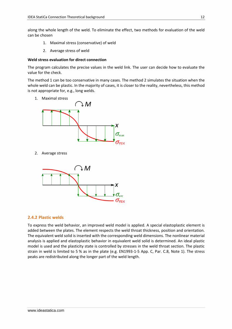
along the whole length of the weld. To eliminate the effect, two methods for evaluation of the weld can be chosen
1. Maximal stress (conservative) of weld
2. Average stress of weld
Weld stress evaluation for direct connection
The program calculates the precise values in the weld link. The user can decide how to evaluate the value for the check.
The method 1 can be too conservative in many cases. The method 2 simulates the situation when the whole weld can be plastic. In the majority of cases, it is closer to the reality, nevertheless, this method is not appropriate for, e.g., long welds.
1. Maximal stress
2. Average stress
2.4.2 Plastic welds
To express the weld behavior, an improved weld model is applied. A special elastoplastic element is added between the plates. The element respects the weld throat thickness, position and orientation. The equivalent weld solid is inserted with the corresponding weld dimensions. The nonlinear material analysis is applied and elastoplastic behavior in equivalent weld solid is determined. An ideal plastic model is used and the plasticity state is controlled by stresses in the weld throat section. The plastic strain in weld is limited to 5 % as in the plate (e.g. EN1993-1-5 App. C, Par. C.8, Note 1). The stress peaks are redistributed along the longer part of the weld length.

IDEA StatiCa Connection Theoretical background 13
www.ideastatica.com
Constraint between weld element and mesh nodes
Weld stress evaluation for plastic welds
Fully plastic model of welds gives real values of stress and there is no need to average or interpolate the stress. Calculated values are used directly for checks.
2.5 Bolts
In the Component Based Finite Element Method (CBFEM), bolt with its behavior in tension, shear and bearing is the component described by the dependent nonlinear springs. The bolt in tension is described by spring with its axial initial stiffness, design resistance, initialization of yielding and deformation capacity. The axial initial stiffness is derived analytically in the guideline VDI2230. The model corresponds to experimental data, see Gödrich et al. (2014). For initialization of yielding and deformation capacity, it is assumed that plastic deformation occurs in the threaded part of the bolt shank only. The force at beginning of yielding, 𝐹y,ini, is
𝐹y,ini = 𝑓y,b 𝐴t
where 𝑓y,b is the yield strength of bolts and 𝐴t the tensile area of the bolt. Relation gives higher values
for materials with low ratio of the ultimate strength to yield strength than the design resistance, 𝐹t,Rd.
To assure a positive value of plastic stiffness, it should be taken
𝐹y,ini ≤ 𝐹t,Rd
Deformation capacity of the bolt 𝛿c consists of elastic deformation of bolt shank 𝛿el and plastic one of the threaded part only 𝛿pl.
𝛿c = 𝛿el + 𝛿pl
𝛿el =𝐹t,Rd
𝑘ini
where kini is the initial deformation stiffness of the bolt in tension according to the guideline VDI2230, and
𝛿pl = 휀pl 𝑙t
where 휀pl is the limit plastic strain given by the value of 5% and 𝑙t is the length of the threaded part.
The tensile force is transmitted to the plates by interpolation links between the bolt shank and nodes in the plate. The transfer area corresponds to the mean value of the bolt shank and the circle inscribed in the hexagon of the bolt head.
Deformation capacity is considered according to Wald et al. (2002) as
IDEA StatiCa Connection Theoretical background 14
www.ideastatica.com
𝛿pl = 3 휀el
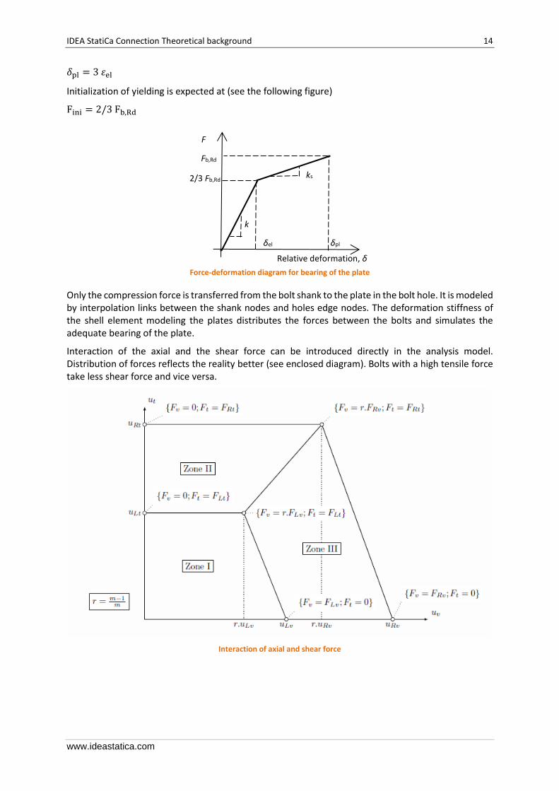
Initialization of yielding is expected at (see the following figure)
Fini = 2/3 Fb,Rd
Force-deformation diagram for bearing of the plate
Only the compression force is transferred from the bolt shank to the plate in the bolt hole. It is modeled by interpolation links between the shank nodes and holes edge nodes. The deformation stiffness of the shell element modeling the plates distributes the forces between the bolts and simulates the adequate bearing of the plate.
Interaction of the axial and the shear force can be introduced directly in the analysis model. Distribution of forces reflects the reality better (see enclosed diagram). Bolts with a high tensile force take less shear force and vice versa.
Interaction of axial and shear force
F
Relative deformation, δ
δel δpl
Fb,Rd
2/3 Fb,Rd
k
ks
IDEA StatiCa Connection Theoretical background 15
www.ideastatica.com
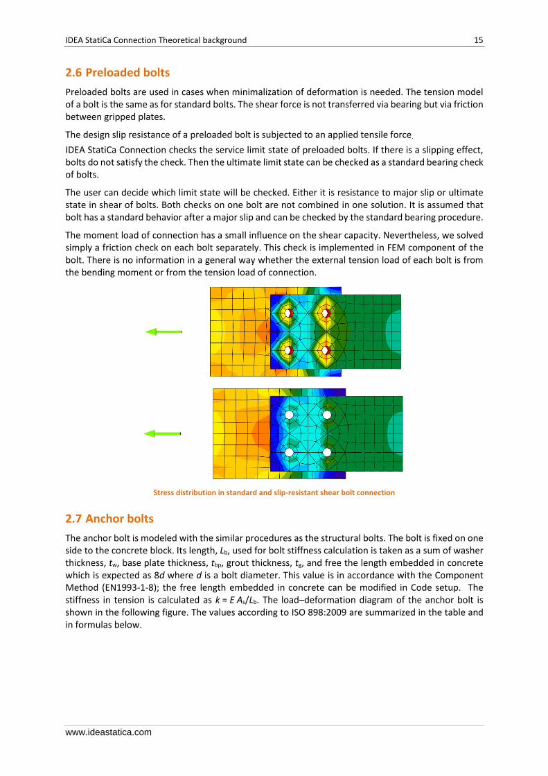
2.6 Preloaded bolts
Preloaded bolts are used in cases when minimalization of deformation is needed. The tension model of a bolt is the same as for standard bolts. The shear force is not transferred via bearing but via friction between gripped plates.
The design slip resistance of a preloaded bolt is subjected to an applied tensile force.
IDEA StatiCa Connection checks the service limit state of preloaded bolts. If there is a slipping effect, bolts do not satisfy the check. Then the ultimate limit state can be checked as a standard bearing check of bolts.
The user can decide which limit state will be checked. Either it is resistance to major slip or ultimate state in shear of bolts. Both checks on one bolt are not combined in one solution. It is assumed that bolt has a standard behavior after a major slip and can be checked by the standard bearing procedure.
The moment load of connection has a small influence on the shear capacity. Nevertheless, we solved simply a friction check on each bolt separately. This check is implemented in FEM component of the bolt. There is no information in a general way whether the external tension load of each bolt is from the bending moment or from the tension load of connection.
Stress distribution in standard and slip-resistant shear bolt connection
2.7 Anchor bolts
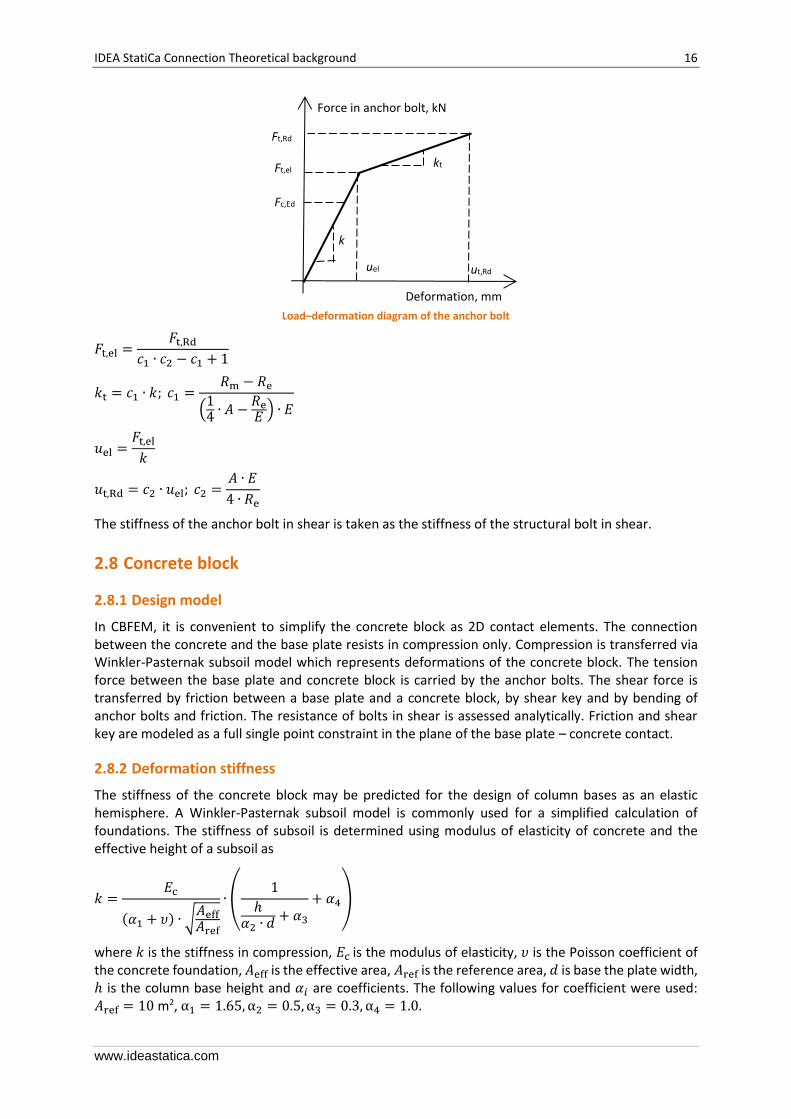
The anchor bolt is modeled with the similar procedures as the structural bolts. The bolt is fixed on one side to the concrete block. Its length, Lb, used for bolt stiffness calculation is taken as a sum of washer thickness, tw, base plate thickness, tbp, grout thickness, tg, and free the length embedded in concrete which is expected as 8d where d is a bolt diameter. This value is in accordance with the Component Method (EN1993-1-8); the free length embedded in concrete can be modified in Code setup. The stiffness in tension is calculated as k = E As/Lb. The load–deformation diagram of the anchor bolt is shown in the following figure. The values according to ISO 898:2009 are summarized in the table and in formulas below.
IDEA StatiCa Connection Theoretical background 16
www.ideastatica.com
Load–deformation diagram of the anchor bolt
𝐹t,el =𝐹t,Rd
𝑐1 ∙ 𝑐2 − 𝑐1 + 1
𝑘t = 𝑐1 ∙ 𝑘; 𝑐1 =𝑅m − 𝑅e
(14
∙ 𝐴 −𝑅e𝐸
) ∙ 𝐸
𝑢el =𝐹t,el
𝑘
𝑢t,Rd = 𝑐2 ∙ 𝑢el; 𝑐2 =𝐴 ∙ 𝐸
4 ∙ 𝑅e
The stiffness of the anchor bolt in shear is taken as the stiffness of the structural bolt in shear.
2.8 Concrete block
2.8.1 Design model
In CBFEM, it is convenient to simplify the concrete block as 2D contact elements. The connection between the concrete and the base plate resists in compression only. Compression is transferred via Winkler-Pasternak subsoil model which represents deformations of the concrete block. The tension force between the base plate and concrete block is carried by the anchor bolts. The shear force is transferred by friction between a base plate and a concrete block, by shear key and by bending of anchor bolts and friction. The resistance of bolts in shear is assessed analytically. Friction and shear key are modeled as a full single point constraint in the plane of the base plate – concrete contact.
2.8.2 Deformation stiffness
The stiffness of the concrete block may be predicted for the design of column bases as an elastic hemisphere. A Winkler-Pasternak subsoil model is commonly used for a simplified calculation of foundations. The stiffness of subsoil is determined using modulus of elasticity of concrete and the effective height of a subsoil as
𝑘 =𝐸c
(𝛼1 + 𝜐) ∙ √𝐴eff𝐴ref
∙ (1
ℎ𝛼2 ∙ 𝑑
+ 𝛼3
+ 𝛼4)
where 𝑘 is the stiffness in compression, 𝐸c is the modulus of elasticity, 𝜐 is the Poisson coefficient of the concrete foundation, 𝐴eff is the effective area, 𝐴ref is the reference area, 𝑑 is base the plate width, ℎ is the column base height and 𝛼𝑖 are coefficients. The following values for coefficient were used: 𝐴ref = 10 m2, α1 = 1.65, α2 = 0.5, α3 = 0.3, α4 = 1.0.
Force in anchor bolt, kN
Deformation, mm
uel ut,Rd
Ft,Rd
Ft,el
Fc,Ed
k
kt
IDEA StatiCa Connection Theoretical background 17
www.ideastatica.com
3 Analysis
3.1 Analysis model
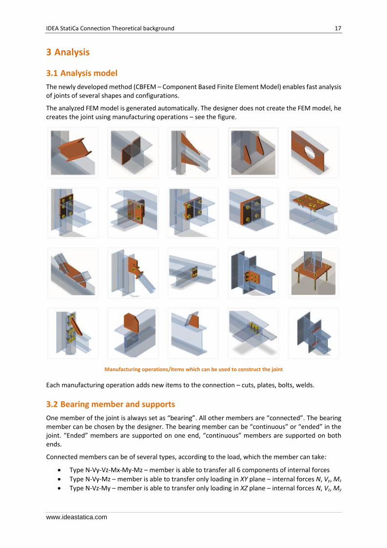
The newly developed method (CBFEM – Component Based Finite Element Model) enables fast analysis of joints of several shapes and configurations.
The analyzed FEM model is generated automatically. The designer does not create the FEM model, he creates the joint using manufacturing operations – see the figure.
Manufacturing operations/items which can be used to construct the joint
Each manufacturing operation adds new items to the connection – cuts, plates, bolts, welds.
3.2 Bearing member and supports
One member of the joint is always set as “bearing”. All other members are “connected”. The bearing member can be chosen by the designer. The bearing member can be “continuous” or “ended” in the joint. “Ended” members are supported on one end, “continuous” members are supported on both ends.
Connected members can be of several types, according to the load, which the member can take:
• Type N-Vy-Vz-Mx-My-Mz – member is able to transfer all 6 components of internal forces
• Type N-Vy-Mz – member is able to transfer only loading in XY plane – internal forces N, Vy, Mz
• Type N-Vz-My – member is able to transfer only loading in XZ plane – internal forces N, Vz, My

IDEA StatiCa Connection Theoretical background 18
www.ideastatica.com
• Type N-Vy-Vz – member is able to transfer only normal force N and shear forces Vy and Vz
Plate to plate connection transfers all components of internal forces
Fin plate connection can transfer only loads in XZ plane – internal forces N, Vz, My
Gusset connection – connection of truss member can transfer only axial force N and shear forces Vy and Vz
IDEA StatiCa Connection Theoretical background 19
www.ideastatica.com
Each joint is in the state of equilibrium during the analysis of the frame structure. If the end forces of the individual members are applied to detailed CBFEM model, the state of equilibrium is met too. Thus, it would not be necessary to define supports in analysis model. However, for practical reasons, the support resisting all translations is defined in the first end of the bearing member. It does influence neither the state of stress nor the internal forces in the joint, only the presentation of deformations.
Appropriate support types respecting the type of the individual members are defined at the ends of the connected members to prevent the occurrence of unstable mechanisms.
3.3 Equilibrium in node
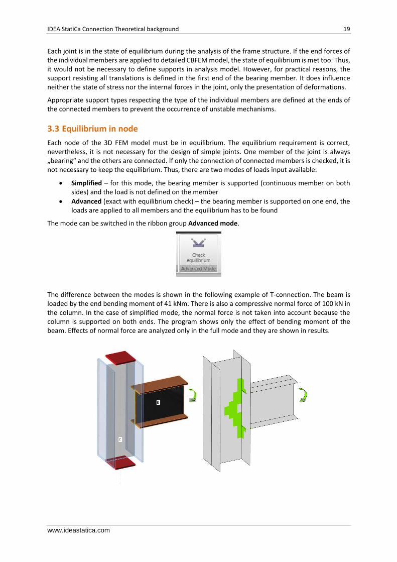
Each node of the 3D FEM model must be in equilibrium. The equilibrium requirement is correct, nevertheless, it is not necessary for the design of simple joints. One member of the joint is always „bearing“ and the others are connected. If only the connection of connected members is checked, it is not necessary to keep the equilibrium. Thus, there are two modes of loads input available:
• Simplified – for this mode, the bearing member is supported (continuous member on both sides) and the load is not defined on the member
• Advanced (exact with equilibrium check) – the bearing member is supported on one end, the loads are applied to all members and the equilibrium has to be found
The mode can be switched in the ribbon group Advanced mode.
The difference between the modes is shown in the following example of T-connection. The beam is loaded by the end bending moment of 41 kNm. There is also a compressive normal force of 100 kN in the column. In the case of simplified mode, the normal force is not taken into account because the column is supported on both ends. The program shows only the effect of bending moment of the beam. Effects of normal force are analyzed only in the full mode and they are shown in results.

IDEA StatiCa Connection Theoretical background 20
www.ideastatica.com
Simplified input: normal force in column is NOT taken into account
Advanced input: normal force in column is taken into account
The simplified method is easier for the user but it can be used only when the user is interested in studying connection items and not the behavior of the whole joint. For cases where the bearing member is heavily loaded and close to its limit capacity, the advanced mode with respecting all the internal forces in the joint is necessary.
3.4 Loads
The end forces of a member of the frame analysis model are transferred to the ends of member segments. Eccentricities of the members caused by the joint design are respected during transfer.
The analysis model created by CBFEM method corresponds to the real joint very precisely, whereas the analysis of internal forces is performed on much idealized 3D FEM bar model, where individual beams are modeled using center lines and the joints are modeled using immaterial nodes.
IDEA StatiCa Connection Theoretical background 21
www.ideastatica.com
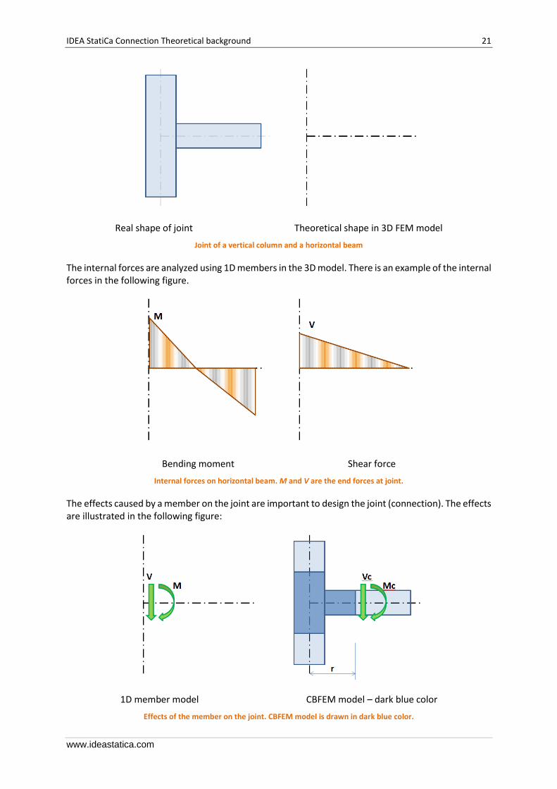
Real shape of joint Theoretical shape in 3D FEM model
Joint of a vertical column and a horizontal beam
The internal forces are analyzed using 1D members in the 3D model. There is an example of the internal forces in the following figure.
Bending moment Shear force
Internal forces on horizontal beam. M and V are the end forces at joint.
The effects caused by a member on the joint are important to design the joint (connection). The effects are illustrated in the following figure:
1D member model CBFEM model – dark blue color
Effects of the member on the joint. CBFEM model is drawn in dark blue color.
IDEA StatiCa Connection Theoretical background 22
www.ideastatica.com
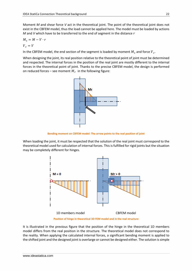
Moment M and shear force V act in the theoretical joint. The point of the theoretical joint does not exist in the CBFEM model, thus the load cannot be applied here. The model must be loaded by actions M and V which have to be transferred to the end of segment in the distance 𝑟
𝑀c = 𝑀 − 𝑉 ∙ 𝑟
𝑉𝑐 = 𝑉
In the CBFEM model, the end section of the segment is loaded by moment 𝑀c and force 𝑉𝑐 .
When designing the joint, its real position relative to the theoretical point of joint must be determined and respected. The internal forces in the position of the real joint are mostly different to the internal forces in the theoretical point of joint. Thanks to the precise CBFEM model, the design is performed on reduced forces – see moment 𝑀𝑟 in the following figure:
Bending moment on CBFEM model: The arrow points to the real position of joint
When loading the joint, it must be respected that the solution of the real joint must correspond to the theoretical model used for calculation of internal forces. This is fulfilled for rigid joints but the situation may be completely different for hinges.
1D members model CBFEM model
Position of hinge in theoretical 3D FEM model and in the real structure
It is illustrated in the previous figure that the position of the hinge in the theoretical 1D members model differs from the real position in the structure. The theoretical model does not correspond to the reality. When applying the calculated internal forces, a significant bending moment is applied to the shifted joint and the designed joint is overlarge or cannot be designed either. The solution is simple

IDEA StatiCa Connection Theoretical background 23
www.ideastatica.com
– both models must correspond. Either the hinge in 1D member model must be defined in the proper position or the shear force must be shifted to get a zero moment in the position of the hinge.
Shifted distribution of bending moment on beam: zero moment is at the position of the hinge
The shift of the shear force can be defined in the table for the internal forces definition.
The location of load effect has a big influence on the correct design of the connection. To avoid all misunderstandings, we allow the user to select from three options – Node / Bolts / Position.

IDEA StatiCa Connection Theoretical background 24
www.ideastatica.com
3.4.1 Import loads from FEA programs
IDEA StatiCa enables to import internal forces from third-party FEA programs. FEA programs use an envelope of internal forces from combinations. IDEA StatiCa Connection is a program which resolves steel joint nonlinearly (elastic/plastic material model). Therefore the envelope combinations cannot be used. IDEA StatiCa searches for extremes of internal forces (N, Vy, Vz, Mx, My, Mz) in all combinations at the ends of all members connected to the joint. For each such extreme value also all other internal forces from that combination on all remaining members are used. Idea StatiCa determines the worst combination for each component (plate, weld, bolt etc.) in the connection.
The user can modify this list of load cases. He can work with combinations in the wizard (or BIM) or he can delete some cases directly in IDEA StatiCa Connection.
3.5 Strength analysis
The analysis of joint is materially non-linear. The load increments are applied gradually and the state of stress is searched. There are two optional analysis modes in IDEA Connection:
• The response of structure (joint) to the overall load. All defined load (100 %) is applied in this mode and the corresponding state of stress and deformation is calculated.
• Analysis termination at reaching the ultimate limit state. The checkbox in Code setup “Stop
at limit strain” should be ticked. The state is found when the plastic strain reaches the defined limit. In the case when the defined load is higher than the calculated capacity, the analysis is marked as non-satisfying and the percentage of used load is printed. Note that the analytical resistance of components, for example of bolts, can be exceeded.
The second mode is more suitable for a practical design. The first one is preferable for detailed analysis of complex joints.
IDEA StatiCa Connection Theoretical background 25
www.ideastatica.com
3.6 Stiffness analysis
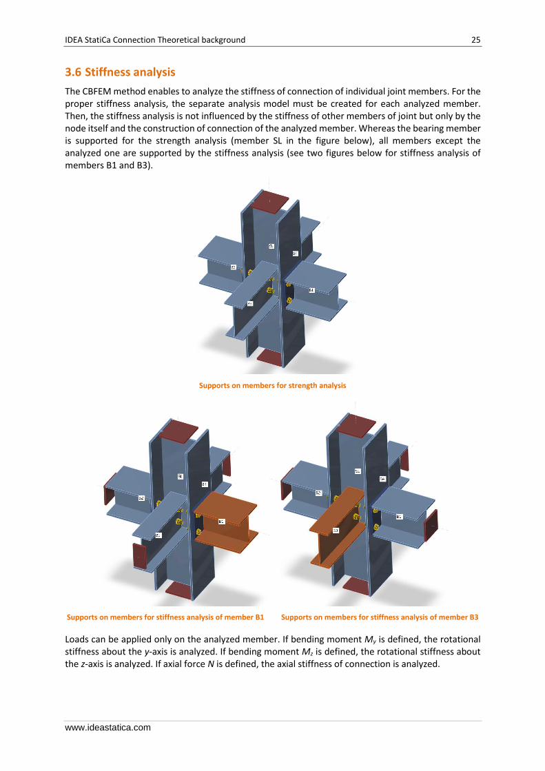
The CBFEM method enables to analyze the stiffness of connection of individual joint members. For the proper stiffness analysis, the separate analysis model must be created for each analyzed member. Then, the stiffness analysis is not influenced by the stiffness of other members of joint but only by the node itself and the construction of connection of the analyzed member. Whereas the bearing member is supported for the strength analysis (member SL in the figure below), all members except the analyzed one are supported by the stiffness analysis (see two figures below for stiffness analysis of members B1 and B3).
Supports on members for strength analysis
Supports on members for stiffness analysis of member B1 Supports on members for stiffness analysis of member B3
Loads can be applied only on the analyzed member. If bending moment My is defined, the rotational stiffness about the y-axis is analyzed. If bending moment Mz is defined, the rotational stiffness about the z-axis is analyzed. If axial force N is defined, the axial stiffness of connection is analyzed.
IDEA StatiCa Connection Theoretical background 26
www.ideastatica.com
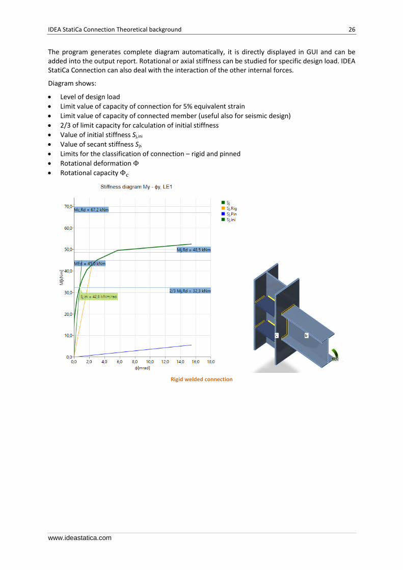
The program generates complete diagram automatically, it is directly displayed in GUI and can be added into the output report. Rotational or axial stiffness can be studied for specific design load. IDEA StatiCa Connection can also deal with the interaction of the other internal forces.
Diagram shows:
• Level of design load
• Limit value of capacity of connection for 5% equivalent strain
• Limit value of capacity of connected member (useful also for seismic design)
• 2/3 of limit capacity for calculation of initial stiffness
• Value of initial stiffness Sj,ini
• Value of secant stiffness Sjs
• Limits for the classification of connection – rigid and pinned
• Rotational deformation Φ
• Rotational capacity Φc
Rigid welded connection
IDEA StatiCa Connection Theoretical background 27
www.ideastatica.com
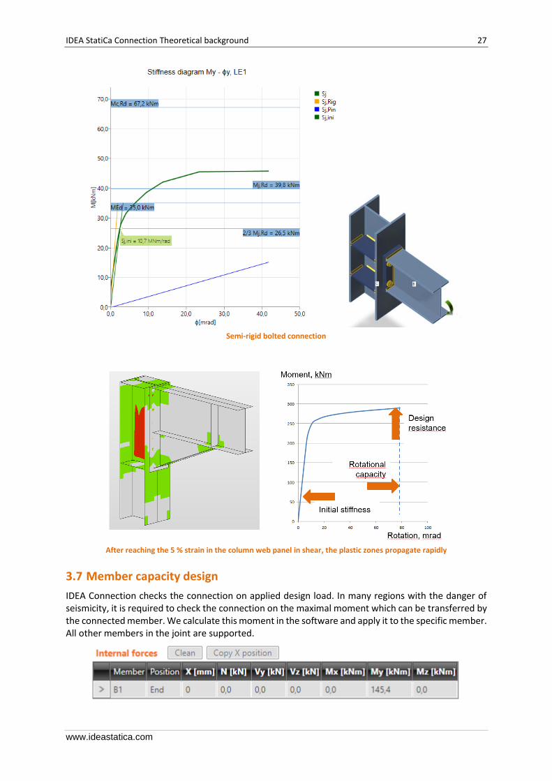
Semi-rigid bolted connection
After reaching the 5 % strain in the column web panel in shear, the plastic zones propagate rapidly
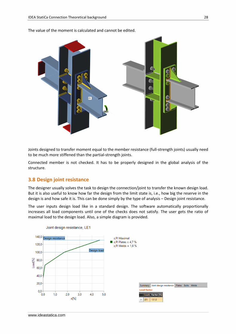
3.7 Member capacity design
IDEA Connection checks the connection on applied design load. In many regions with the danger of seismicity, it is required to check the connection on the maximal moment which can be transferred by the connected member. We calculate this moment in the software and apply it to the specific member. All other members in the joint are supported.
IDEA StatiCa Connection Theoretical background 28
www.ideastatica.com
The value of the moment is calculated and cannot be edited.
Joints designed to transfer moment equal to the member resistance (full-strength joints) usually need to be much more stiffened than the partial-strength joints.
Connected member is not checked. It has to be properly designed in the global analysis of the structure.
3.8 Design joint resistance
The designer usually solves the task to design the connection/joint to transfer the known design load. But it is also useful to know how far the design from the limit state is, i.e., how big the reserve in the design is and how safe it is. This can be done simply by the type of analysis – Design joint resistance.
The user inputs design load like in a standard design. The software automatically proportionally increases all load components until one of the checks does not satisfy. The user gets the ratio of maximal load to the design load. Also, a simple diagram is provided.

IDEA StatiCa Connection Theoretical background 29
www.ideastatica.com
3.9 Stability analysis
IDEA StatiCa Connection is able to perform linear buckling analysis and provide the user with the buckling factor.
It is important to recognize the global buckling (buckling of whole members) and the local buckling (buckling of individual plates). In the case of global buckling (the plate is an elongation of a member, see figure below), it is recommended to check the buckling resistance for buckling factor smaller than 15.
Critical buckling factor for a gusset plate as an elongation of a truss
In the case of most plates in connections, local buckling can occur and the maximum value of the critical buckling factor that requires thorough the analysis is usually smaller; it has been verified that for stiffeners and column panel in shear, it is not necessary to take into account buckling if the critical buckling factor is higher than 3.
Examples of buckling shapes where the buckling can be neglected if critical buckling factor is higher than 3
It is possible to follow the results of IDEA StatiCa Connection with calculations or with geometrically nonlinear analysis with initial imperfections in advanced FEM software if the buckling factor is smaller than the critical value. Nevertheless, it is often more economical to use stiffeners or thicker plates in design.

IDEA StatiCa Connection Theoretical background 30
www.ideastatica.com
3.10 Deformation capacity
The deformation capacity/ductility δCd belongs with the resistance and the stiffness to the three basic parameters describing the behavior of connections. In moment-resistant connections, the ductility is achieved by a sufficient rotation capacity φCd. The deformation/rotation capacity is calculated for each connection in the joint separately.
The estimation of the rotation capacity is important in connections exposed to seismic, see Gioncu and Mazzolani (2002) and Grecea (2004) and extreme loading, see Sherbourne and Bahaari (1994 and 1996). The deformation capacity of components has been studied from the end of the last century (Foley and Vinnakota, 1995). Faella et al. (2000) carried out tests on T-stubs and derived the analytical expressions for the deformation capacity. Kuhlmann and Kuhnemund (2000) performed tests on the column web subjected to transverse compression at different levels of compression axial force in the column. Da Silva et al. (2002) predicted deformation capacity at different levels of axial force in the connected beam. Based on the test results combined with FE analysis, deformation capacities are established for the basic components by analytical models by Beg et al. (2004). In the work, components are represented by non-linear springs and appropriately combined in order to determine the rotation capacity of the joint for the end-plate connections, with an extended or flush end-plate and welded connections. For these connections, the most important components that may significantly contribute to the rotation capacity were recognized as the web in compression, column web in tension, column web in shear, column flange in bending, and end-plate in bending. Components related to the column web are relevant only when there are no stiffeners in the column that resist compression, tension or shear forces. The presence of a stiffener eliminates the corresponding component, and its contribution to the rotation capacity of the joint can be therefore neglected. End-plates and column flanges are important only for end-plate connections where the components act as a T-stub, where also the deformation capacity of the bolts in tension is included. The questions and limits of deformation capacity of connections of high strength steel were studied by Girao at al. (2004).
IDEA StatiCa Connection Theoretical background 31
www.ideastatica.com
4 Check of components according to Eurocode
CBFEM method combines advantages of general Finite Element Method (FEM) and standard Component Method (CM). The stresses and internal forces calculated on the accurate CBFEM model are used in checks of all components.
Individual components are checked according to Eurocode EN 1993-1-8.
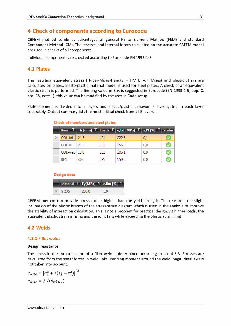
4.1 Plates
The resulting equivalent stress (Huber-Mises-Hencky – HMH, von Mises) and plastic strain are calculated on plates. Elasto-plastic material model is used for steel plates. A check of an equivalent plastic strain is performed. The limiting value of 5 % is suggested in Eurocode (EN 1993-1-5, app. C, par. C8, note 1), this value can be modified by the user in Code setup.
Plate element is divided into 5 layers and elastic/plastic behavior is investigated in each layer separately. Output summary lists the most critical check from all 5 layers.
CBFEM method can provide stress rather higher than the yield strength. The reason is the slight inclination of the plastic branch of the stress-strain diagram which is used in the analysis to improve the stability of interaction calculation. This is not a problem for practical design. At higher loads, the equivalent plastic strain is rising and the joint fails while exceeding the plastic strain limit.
4.2 Welds
4.2.1 Fillet welds
Design resistance
The stress in the throat section of a fillet weld is determined according to art. 4.5.3. Stresses are calculated from the shear forces in weld links. Bending moment around the weld longitudinal axis is not taken into account.
𝜎w,Ed = [𝜎⊥2 + 3(𝜏⊥
2 + 𝜏∥2)]
0.5
𝜎w,Rd = 𝑓u (𝛽w𝛾M2)⁄

IDEA StatiCa Connection Theoretical background 32
www.ideastatica.com
Weld utilisation
𝑈t = min{𝜎w,Ed 𝜎w,Rd; 𝜎⊥ (0.9𝑓u 𝛾M2⁄ )⁄⁄ }
where 𝛽w is a correlation factor in Tab 4.1 in EN 1993-1-8.
Stresses in the weld
All values required for check are printed in tables.
4.2.2 Butt welds
Welds can be specified as butt welds. Complete joint penetration is considered for butt welds, thus such welds are not checked.
4.3 Bolts
The initial stiffness and design resistance of bolts in shear are in CBFEM modeled according to Cl. 3.6 and 6.3.2 in EN 1993-1-8. Linear behavior up to failure is considered.

IDEA StatiCa Connection Theoretical background 33
www.ideastatica.com
The spring representing bearing has a bi-linear force-deformation behavior with an initial stiffness and design resistance according to Cl. 3.6 and 6.3.2 in EN 1993-1-8.
Design tension resistance of bolt: 𝐹t,Rd = 0.9 𝑓ub𝐴s 𝛾M2⁄
Design shear resistance at punching of bolt head or nut EN 1993-1-8: 𝐵p,Rd = 0.6𝜋 𝑑m𝑡p𝑓u 𝛾M2⁄
Design shear resistance per one shear plane: 𝐹V,Rd = 𝛼V𝑓ub𝐴s 𝛾M2⁄
Design shear resistance can be multiplied by reduction factor 𝛽𝑝 if packing is present (EN 1993-1-8 –
Cl. 3.6.1. (12)) and this option is selected in Code setup.
Design bearing resistance of plate EN 1993-1-8: 𝐹b,Rd = 𝑘1𝑎b𝑓u𝑑𝑡 𝛾M2⁄
Utilisation in tension [%]:
𝑈tt = 𝐹t,Ed min(𝐹t,Rd, 𝐵p,Rd)⁄
Utilisation in shear [%]:
𝑈ts = 𝑉 min(𝐹V,Rd, 𝐹b,Rd)⁄
Interaction of shear and tension [%]: 𝑈tts = 𝑉 𝐹V,Rd⁄ + 𝐹t,Ed 1.4𝐹t,Rd⁄
where:
• As – tensile stress area of the bolt
• fub – ultimate tensile strength
• 𝑑m – bolt head diameter
• 𝑑 – bolt diameter
• 𝑡p – plate thickness under the bolt head/nut
• 𝑓u – ultimate steel strength
• 𝛼V = 0.6 for classes (4.6, 5.6, 8.8) or 0.5 for classes (4.8, 5.8, 6.8, 10,9)
• 𝑘1 = 2.5
• 𝑎b = 1.0 if the bearing check with ab is deactivated in Code setup; if the check is activated, the value of 𝑎b is determined according to EN 1993-1-8 – Table 3.4
• 𝐹t,Ed – design tensile force in bolt
• 𝑉 – design shear force in bolt

IDEA StatiCa Connection Theoretical background 34
www.ideastatica.com
4.4 Preloaded bolts
The design slip resistance of a preloaded class 8.8 or 10.9 bolts is subjected to an applied tensile force, 𝐹t,Ed. Preloading force of bolt with tensile stress area 𝐴s to be used EN 1993-1-8, Cl. 3.9 (3.7) 𝐹p,C = 0.7𝑓ub𝐴s
Design slip resistance per bolt according to EN 1993-1-8, Cl. 3.9 (3.8)
𝐹s,Rd = 𝑘𝑠 𝑛 𝜇 (𝐹p,C − 0.8 𝐹t,Ed) 𝛾M3⁄
where 𝑘𝑠 is a coefficient given in Table 3.6, 𝜇 is slip factor, 𝑛 is number of the friction surfaces and 𝛾M3 is a safety factor.
Utilization in shear [%]: 𝑈ts = 𝑉 𝐹s,Rd⁄
where:
• 𝐴s – tensile stress area of the bolt • 𝑓ub – ultimate tensile strength • 𝑘𝑠 – coefficient given in Table 3.6; if bolts in normal holes are assumed 𝑘𝑠 = 1 • 𝜇 – slip factor editable in Code setup, see Table 3.7 • 𝑛 – number of the friction surfaces. Check is calculated for each friction surface separately • 𝛾M3 – safety factor • 𝑉 – design shear force in bolt • 𝐹t,Ed – design tensile force in bolt
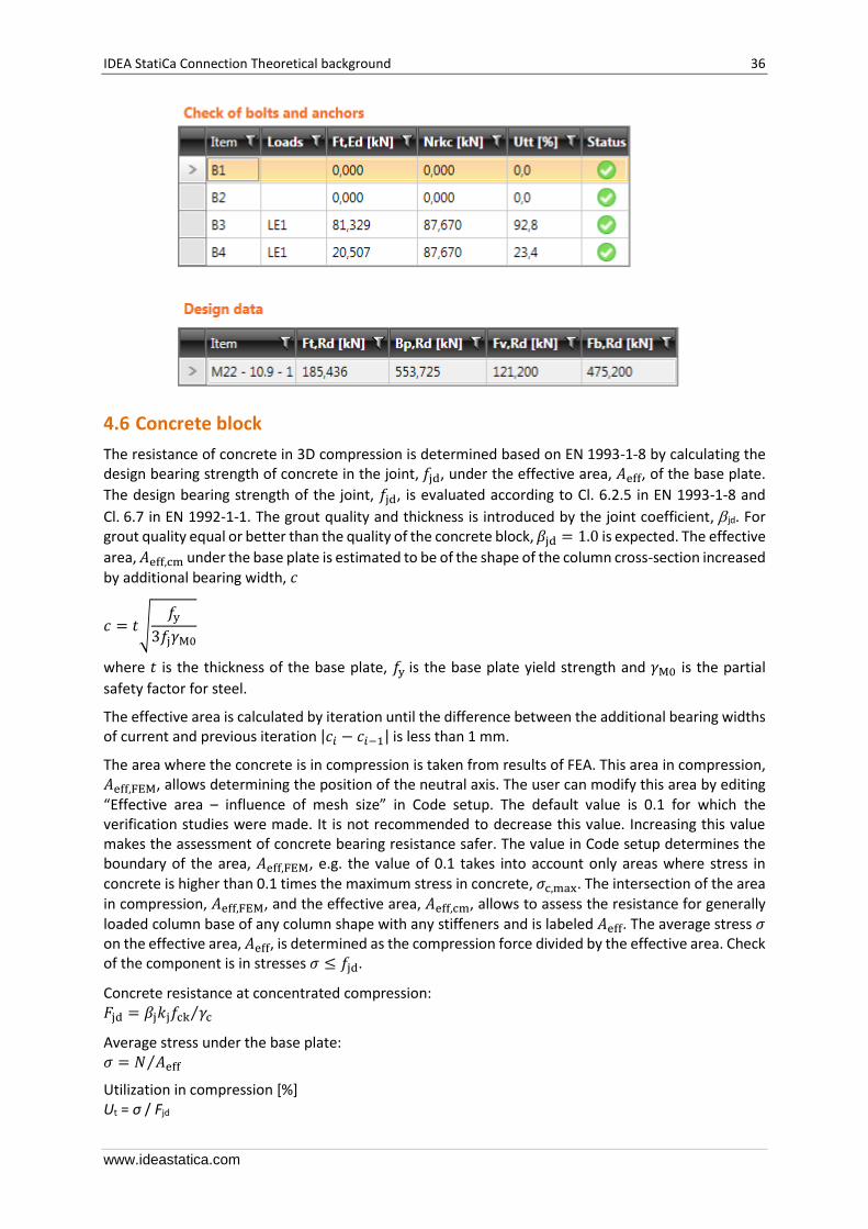
4.5 Anchors
The anchor bolt resistance caused by concrete failure is evaluated according to ETAG 001 Annex C. Steel failure mode is determined according to Cl. 6.2.6.12 in EN 1993-1-8.
Concrete cone failure resistance of anchor or group of anchors (ETAG-001 – 5.2.2.4):
𝑁Rk,c = 𝑁Rk,c0 𝐴c,N 𝐴c,N
0⁄ Ψs,NΨre,N
IDEA StatiCa Connection Theoretical background 35
www.ideastatica.com
The initial value of characteristic resistance:
𝑁Rk,c0 = 7.2𝑓ck,cube
0.5 ℎef1.5
where:
• 𝐴c,N0 – area of concrete of an individual anchor with large spacing and edge distance at
the concrete surface
• ℎef – the length of the anchor in concrete
• 𝑓ck,cube – characteristic cubic concrete compressive strength
• 𝐴c,N – actual area of concrete cone of the anchorage at the concrete surface respecting influence of edges and adjoining anchors
• Ψs,N = 1.0
• Ψre,N = 1.0
Anchor shear resistance in case of transfer of shear forces. Friction is not taken into account. Valid in case, that the anchor failure precedes the concrete failure (ETAG-001 – 5.2.3.2): 𝑉Rk,s = 0.5𝑓y𝐴s
Concrete pry-out failure (ETAG-001 – 5.2.3.3):
𝑉Rk,cp 𝛾Mc⁄ ≥ 𝑉
𝑉Rk,cp = 𝑘𝑁Rk,c
where:
• 𝑉 – the design shear force in anchor
• 𝑘 = 1 for ℎef < 60 mm
• 𝑘 = 2 for ℎef ≥ 60 mm
Concrete edge failure (ETAG-001 – 5.2.3.4):
𝑉Rk,c 𝛾Mc⁄ ≥ 𝑉
𝑉Rk,c = 𝑉Rk,c0 𝐴c,V 𝐴c,V
0⁄ Ψs,VΨre,V
𝑉Rk,c0 = 1.7 𝑑𝛼 𝑙f
𝛽 𝑓ck,cube
0.5 𝑐11.5
𝛼 = 0.1(𝑙f 𝑐1⁄ )0.5
𝛽 = 0.1(𝑑 𝑐1⁄ )0.2
where:
• 𝑙f = ℎef • 𝑐1 – edge distance
• 𝑑 – anchor diameter
• Ψs,V = 1.0
• Ψre,V = 1.0
• 𝐴c,V0 – area of concrete cone of an individual anchor at the lateral concrete surface not affected
by edges (4.5 𝑐12)
• 𝐴c,V – actual area of the concrete cone of anchorage at the lateral concrete surface
IDEA StatiCa Connection Theoretical background 36
www.ideastatica.com
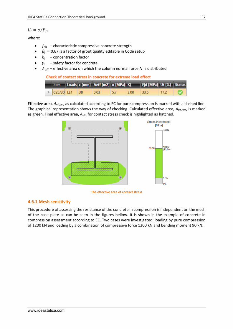
4.6 Concrete block
The resistance of concrete in 3D compression is determined based on EN 1993-1-8 by calculating the design bearing strength of concrete in the joint, 𝑓jd, under the effective area, 𝐴eff, of the base plate.
The design bearing strength of the joint, 𝑓jd, is evaluated according to Cl. 6.2.5 in EN 1993-1-8 and
Cl. 6.7 in EN 1992-1-1. The grout quality and thickness is introduced by the joint coefficient, jd. For grout quality equal or better than the quality of the concrete block, 𝛽jd = 1.0 is expected. The effective
area, 𝐴eff,cm under the base plate is estimated to be of the shape of the column cross-section increased by additional bearing width, 𝑐
𝑐 = 𝑡√𝑓y
3𝑓j𝛾M0
where 𝑡 is the thickness of the base plate, 𝑓y is the base plate yield strength and 𝛾M0 is the partial
safety factor for steel.
The effective area is calculated by iteration until the difference between the additional bearing widths of current and previous iteration |𝑐𝑖 − 𝑐𝑖−1| is less than 1 mm.
The area where the concrete is in compression is taken from results of FEA. This area in compression, 𝐴eff,FEM, allows determining the position of the neutral axis. The user can modify this area by editing “Effective area – influence of mesh size” in Code setup. The default value is 0.1 for which the verification studies were made. It is not recommended to decrease this value. Increasing this value makes the assessment of concrete bearing resistance safer. The value in Code setup determines the boundary of the area, 𝐴eff,FEM, e.g. the value of 0.1 takes into account only areas where stress in concrete is higher than 0.1 times the maximum stress in concrete, 𝜎c,max. The intersection of the area in compression, 𝐴eff,FEM, and the effective area, 𝐴eff,cm, allows to assess the resistance for generally
loaded column base of any column shape with any stiffeners and is labeled 𝐴eff. The average stress 𝜎 on the effective area, 𝐴eff, is determined as the compression force divided by the effective area. Check of the component is in stresses 𝜎 ≤ 𝑓jd.
Concrete resistance at concentrated compression: 𝐹jd = 𝛽j𝑘j𝑓ck 𝛾c⁄
Average stress under the base plate: 𝜎 = 𝑁 𝐴eff⁄
Utilization in compression [%] Ut = σ / Fjd
IDEA StatiCa Connection Theoretical background 37
www.ideastatica.com
𝑈t = 𝜎 𝐹jd⁄
where:
• 𝑓ck – characteristic compressive concrete strength
• 𝛽j = 0.67 is a factor of grout quality editable in Code setup
• 𝑘j – concentration factor
• 𝛾c – safety factor for concrete
• 𝐴eff – effective area on which the column normal force 𝑁 is distributed
Effective area, Aeff,cm, as calculated according to EC for pure compression is marked with a dashed line. The graphical representation shows the way of checking. Calculated effective area, Aeff,fem, is marked as green. Final effective area, Aeff, for contact stress check is highlighted as hatched.
The effective area of contact stress
4.6.1 Mesh sensitivity
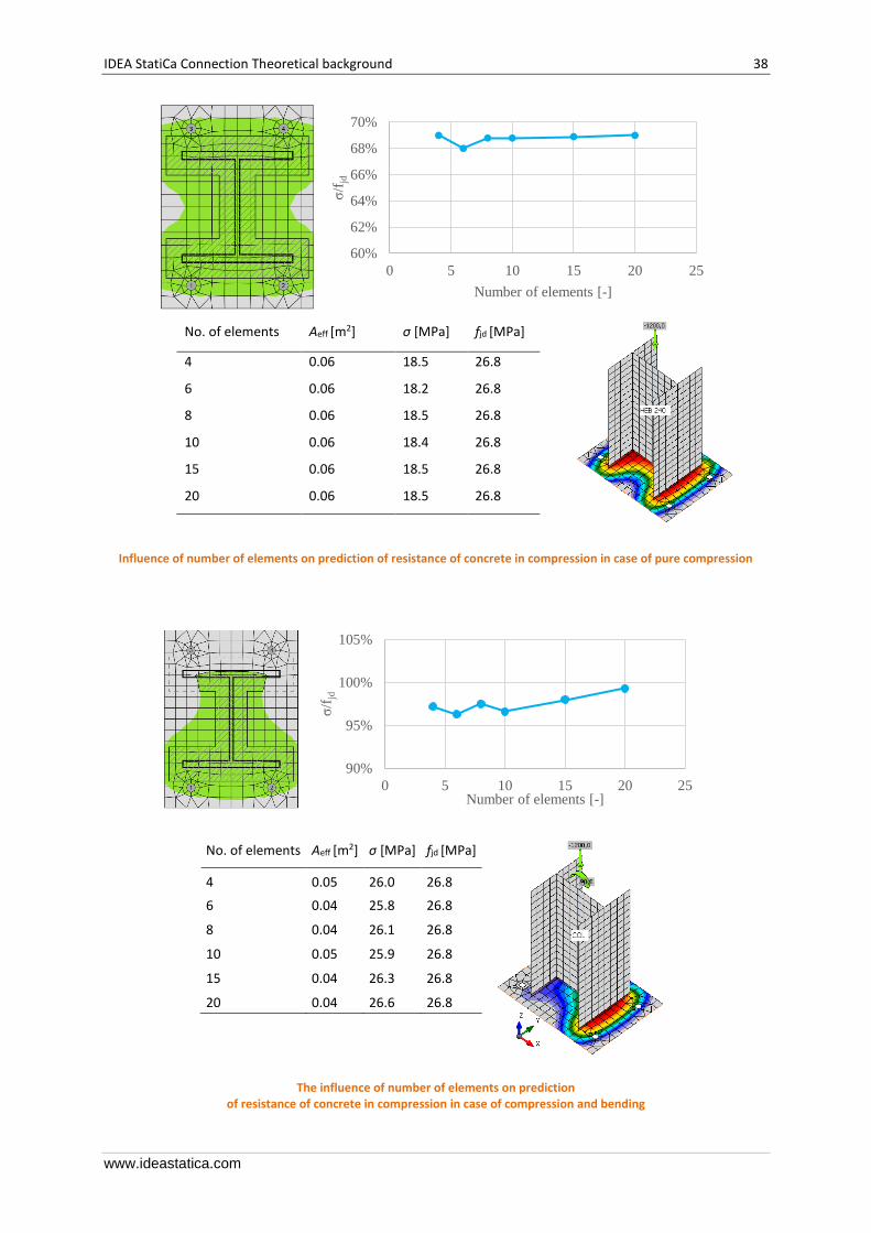
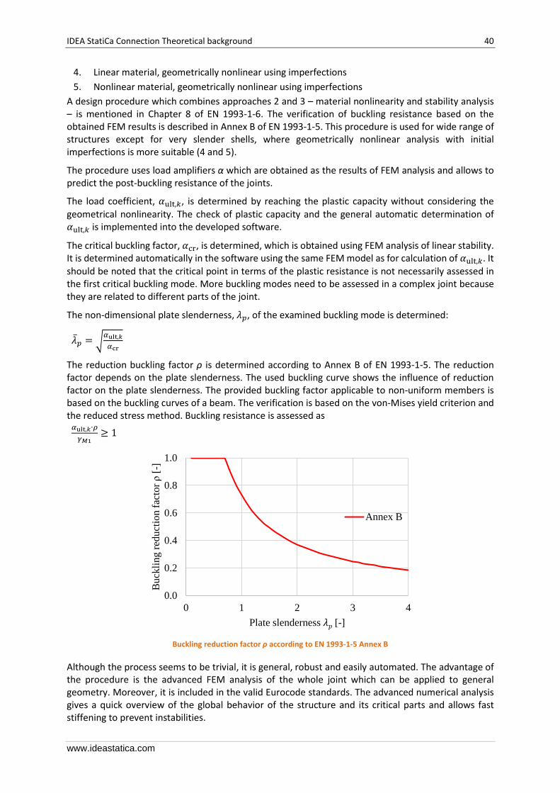
This procedure of assessing the resistance of the concrete in compression is independent on the mesh of the base plate as can be seen in the figures bellow. It is shown in the example of concrete in compression assessment according to EC. Two cases were investigated: loading by pure compression of 1200 kN and loading by a combination of compressive force 1200 kN and bending moment 90 kN.
IDEA StatiCa Connection Theoretical background 38
www.ideastatica.com
No. of elements Aeff [m2] σ [MPa] fjd [MPa]
4 0.06 18.5 26.8
6 0.06 18.2 26.8
8 0.06 18.5 26.8
10 0.06 18.4 26.8
15 0.06 18.5 26.8
20 0.06 18.5 26.8
Influence of number of elements on prediction of resistance of concrete in compression in case of pure compression
No. of elements Aeff [m2] σ [MPa] fjd [MPa]
4 0.05 26.0 26.8
6 0.04 25.8 26.8
8 0.04 26.1 26.8
10 0.05 25.9 26.8
15 0.04 26.3 26.8
20 0.04 26.6 26.8
The influence of number of elements on prediction of resistance of concrete in compression in case of compression and bending
60%
62%
64%
66%
68%
70%
0 5 10 15 20 25
σ/f
jd
Number of elements [-]
90%
95%
100%
105%
0 5 10 15 20 25
σ/f
jd
Number of elements [-]

IDEA StatiCa Connection Theoretical background 39
www.ideastatica.com
4.7 Shear in concrete block
Shear forces are evaluated in this table only in case of shear transfer by friction or shear iron.
1. Shear is transferred only by friction 𝑉Rd,𝑦 = 𝑁𝐶f
𝑉Rd,𝑧 = 𝑁𝐶f
2. Shear is transferred by shear iron and friction
𝑉Rd,𝑦 = 𝑁𝐶f + 𝐴V,𝑦𝑓y (30.5𝛾M0)⁄
𝑉Rd,𝑧 = 𝑁𝐶f + 𝐴V,𝑧𝑓y (30.5𝛾M0)⁄
Utilization in shear [%]
𝑈t = min(𝑉𝑦 𝑉Rd,𝑦⁄ , 𝑉𝑧 𝑉Rd,𝑧⁄ )
where:
• 𝐴V,𝑦 – shear area 𝐴𝑦 of shear iron cross-section
• 𝐴V,𝑧 – shear area 𝐴𝑧 of shear iron cross-section
• 𝑓y – yield strength
• 𝛾M0 – safety factor
• 𝑉𝑦 – shear force component in the base plate plane in y-direction
• 𝑉𝑧 – shear force component in the base plate plane in z-direction
• 𝑁 – force perpendicular to the base plate
• 𝐶f – friction coefficient
4.8 Member capacity design
Member capacity design is performed according to EN 1998
𝑅d ≥ 1.1 𝛾ov 𝑅fy
where:
• 𝑅d – resistance of non-dissipative connection
• 𝑅fy – the yield strength
• 𝛾ov = 1.25
4.9 Stability analysis
There are five categories of finite element structural analysis with following assumptions:
1. Linear material, geometrically linear
2. Nonlinear material, geometrically linear
3. Linear material, linear loss of stability – buckling
IDEA StatiCa Connection Theoretical background 40
www.ideastatica.com
4. Linear material, geometrically nonlinear using imperfections
5. Nonlinear material, geometrically nonlinear using imperfections
A design procedure which combines approaches 2 and 3 – material nonlinearity and stability analysis – is mentioned in Chapter 8 of EN 1993-1-6. The verification of buckling resistance based on the obtained FEM results is described in Annex B of EN 1993-1-5. This procedure is used for wide range of structures except for very slender shells, where geometrically nonlinear analysis with initial imperfections is more suitable (4 and 5).
The procedure uses load amplifiers α which are obtained as the results of FEM analysis and allows to predict the post-buckling resistance of the joints.
The load coefficient, 𝛼ult,𝑘, is determined by reaching the plastic capacity without considering the geometrical nonlinearity. The check of plastic capacity and the general automatic determination of 𝛼ult,𝑘 is implemented into the developed software.
The critical buckling factor, 𝛼cr, is determined, which is obtained using FEM analysis of linear stability. It is determined automatically in the software using the same FEM model as for calculation of 𝛼ult,𝑘. It
should be noted that the critical point in terms of the plastic resistance is not necessarily assessed in the first critical buckling mode. More buckling modes need to be assessed in a complex joint because they are related to different parts of the joint.
The non-dimensional plate slenderness, 𝜆𝑝, of the examined buckling mode is determined:
�̅�𝑝 = √𝛼ult,𝑘
𝛼cr
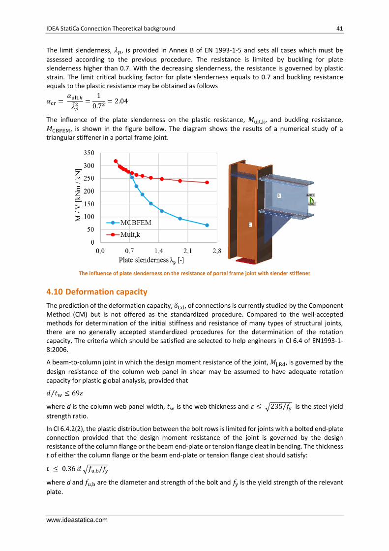
The reduction buckling factor ρ is determined according to Annex B of EN 1993-1-5. The reduction factor depends on the plate slenderness. The used buckling curve shows the influence of reduction factor on the plate slenderness. The provided buckling factor applicable to non-uniform members is based on the buckling curves of a beam. The verification is based on the von-Mises yield criterion and the reduced stress method. Buckling resistance is assessed as
𝛼ult,𝑘∙𝜌
𝛾𝑀1≥ 1
Buckling reduction factor ρ according to EN 1993-1-5 Annex B
Although the process seems to be trivial, it is general, robust and easily automated. The advantage of the procedure is the advanced FEM analysis of the whole joint which can be applied to general geometry. Moreover, it is included in the valid Eurocode standards. The advanced numerical analysis gives a quick overview of the global behavior of the structure and its critical parts and allows fast stiffening to prevent instabilities.
0.0
0.2
0.4
0.6
0.8
1.0
0 1 2 3 4
Bu
ckli
ng r
educt
ion f
acto
r ρ
[-]
Plate slenderness 𝜆𝑝 [-]
Annex B
IDEA StatiCa Connection Theoretical background 41
www.ideastatica.com
The limit slenderness, 𝜆𝑝, is provided in Annex B of EN 1993-1-5 and sets all cases which must be
assessed according to the previous procedure. The resistance is limited by buckling for plate slenderness higher than 0.7. With the decreasing slenderness, the resistance is governed by plastic strain. The limit critical buckling factor for plate slenderness equals to 0.7 and buckling resistance equals to the plastic resistance may be obtained as follows
𝛼cr = 𝛼ult,𝑘
�̅�𝑝2
=1
0.72= 2.04
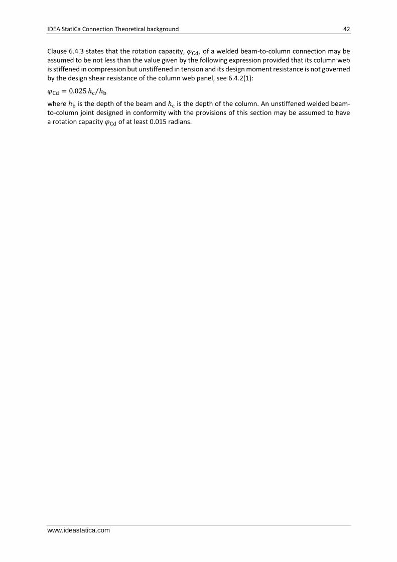
The influence of the plate slenderness on the plastic resistance, 𝑀ult,k, and buckling resistance,
𝑀CBFEM, is shown in the figure bellow. The diagram shows the results of a numerical study of a triangular stiffener in a portal frame joint.
The influence of plate slenderness on the resistance of portal frame joint with slender stiffener
4.10 Deformation capacity
The prediction of the deformation capacity, 𝛿Cd, of connections is currently studied by the Component Method (CM) but is not offered as the standardized procedure. Compared to the well-accepted methods for determination of the initial stiffness and resistance of many types of structural joints, there are no generally accepted standardized procedures for the determination of the rotation capacity. The criteria which should be satisfied are selected to help engineers in Cl 6.4 of EN1993-1-8:2006.
A beam-to-column joint in which the design moment resistance of the joint, 𝑀j,Rd, is governed by the
design resistance of the column web panel in shear may be assumed to have adequate rotation capacity for plastic global analysis, provided that
𝑑 𝑡w ≤ 69휀⁄
where d is the column web panel width, 𝑡w is the web thickness and 휀 ≤ √235/𝑓y
is the steel yield
strength ratio.
In Cl 6.4.2(2), the plastic distribution between the bolt rows is limited for joints with a bolted end-plate connection provided that the design moment resistance of the joint is governed by the design resistance of the column flange or the beam end-plate or tension flange cleat in bending. The thickness t of either the column flange or the beam end-plate or tension flange cleat should satisfy:
𝑡 ≤ 0.36 𝑑 √𝑓u,b/𝑓y
where d and 𝑓u,b are the diameter and strength of the bolt and 𝑓y is the yield strength of the relevant
plate.
IDEA StatiCa Connection Theoretical background 42
www.ideastatica.com
Clause 6.4.3 states that the rotation capacity, 𝜑Cd, of a welded beam-to-column connection may be assumed to be not less than the value given by the following expression provided that its column web is stiffened in compression but unstiffened in tension and its design moment resistance is not governed by the design shear resistance of the column web panel, see 6.4.2(1):
𝜑Cd = 0.025 ℎc ℎb⁄
where ℎb is the depth of the beam and ℎc is the depth of the column. An unstiffened welded beam-to-column joint designed in conformity with the provisions of this section may be assumed to have a rotation capacity 𝜑Cd of at least 0.015 radians.
IDEA StatiCa Connection Theoretical background 43
www.ideastatica.com
5 Check of components according to AISC
CBFEM method combines the advantages of general Finite Element Method and standard Component Method. The stresses and internal forces calculated on the accurate CBFEM model are used in checks of all components.
Individual components are checked according to American Institute of Steel Construction (AISC) 360-16.
5.1 Plates
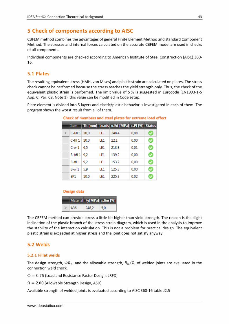
The resulting equivalent stress (HMH, von Mises) and plastic strain are calculated on plates. The stress check cannot be performed because the stress reaches the yield strength only. Thus, the check of the equivalent plastic strain is performed. The limit value of 5 % is suggested in Eurocode (EN1993-1-5 App. C, Par. C8, Note 1), this value can be modified in Code setup.
Plate element is divided into 5 layers and elastic/plastic behavior is investigated in each of them. The program shows the worst result from all of them.
The CBFEM method can provide stress a little bit higher than yield strength. The reason is the slight inclination of the plastic branch of the stress-strain diagram, which is used in the analysis to improve the stability of the interaction calculation. This is not a problem for practical design. The equivalent plastic strain is exceeded at higher stress and the joint does not satisfy anyway.
5.2 Welds
5.2.1 Fillet welds
The design strength, Φ𝑅n, and the allowable strength, 𝑅n Ω⁄ , of welded joints are evaluated in the connection weld check.
Φ = 0.75 (Load and Resistance Factor Design, LRFD)
Ω = 2.00 (Allowable Strength Design, ASD)
Available strength of welded joints is evaluated according to AISC 360-16 table J2.5
IDEA StatiCa Connection Theoretical background 44
www.ideastatica.com
𝑅n = 𝐹nw 𝐴we
𝐹nw = 0.6 𝐹EXX(1.0 + 0.5 sin(1.5𝜃))
where:
• 𝐹nw – nominal stress of weld material
• 𝐴we – effective area of the weld
• 𝐹EXX – electrode classification number, i.e., minimum specified tensile strength
• 𝜃 – angle of loading measured from the weld longitudinal axis, degrees
For end-loaded fillet welds with a length up to 100 times the weld size, it is permitted to take the effective length equal to the actual length. When the length of the end-loaded fillet weld exceeds 100 times the weld size, the effective length shall be determined by multiplying the actual length by the reduction factor, 𝛽, determined as follows:
𝛽 = 1.2 − 0.002(𝑙 𝑤⁄ )
• 𝑙 – weld length
• 𝑤 – the size of weld leg
When the length of the weld exceeds 300 times the leg size, 𝑤, the effective length is taken as 180 𝑤.
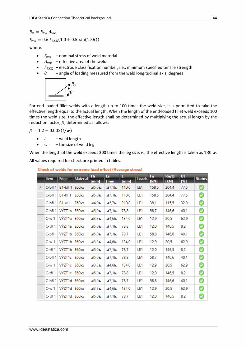
All values required for check are printed in tables.
IDEA StatiCa Connection Theoretical background 45
www.ideastatica.com
5.2.2 CJP groove welds
AISC Specification Table J2.5 identifies four loading conditions that might be associated with groove welds and shows that the strength of the joint is either controlled by the base metal or that the loads need not be considered in the design of the welds connecting the parts. Accordingly, when Complete Joint Penetration (CJP) groove welds are made with matching-strength filler metal, the strength of a connection is governed or controlled by the base metal and no checks on the weld strength are required.
5.3 Bolts
5.3.1 Tensile and shear strength of bolts
The design tensile or shear strength, Φ𝑅n, and the allowable tensile or shear strength, 𝑅n Ω⁄ of a snug-tightened bolt is determined according to the limit states of tension rupture and shear rupture as follows:
𝑅n = 𝐹n 𝐴b
Φ = 0.75 (LRFD)
Ω = 2.00 (ASD)
where:
• 𝐴b – nominal unthreaded body area of bolt or threaded part
• 𝐹n – nominal tensile stress, 𝐹nt, or shear stress, 𝐹nv, from Table J3.2
The required tensile strength includes any tension resulting from prying action produced by the deformation of the connected parts.
5.3.2 Combined Tension and shear in bearing type connection
The available tensile strength of a bolt subjected to combined tension and shear is determined according to the limit states of tension and shear rupture as follows:
𝑅n = 𝐹′nt 𝐴b (AISC 360-16 J3-2)
Φ = 0.75 (LRFD)
Ω = 2.00 (ASD)
𝐹′nt = 1.3𝐹nt − 𝑓rv 𝐹nt (Φ𝐹nv)⁄ (AISC 360-16 J3-3a LRFD)
𝐹′nt = 1.3𝐹nt − 𝑓rv Ω 𝐹nt 𝐹nv⁄ (AISC 360-16 J3-3b ASD)
where:
• 𝐹′nt – nominal tensile stress modified to include the effects of shear stress
• 𝐹nt – nominal tensile stress from AISC 360-16 Table J3.2
• 𝐹nv – nominal shear stress from AISC 360-16 Table J3.2
• 𝑓rv – required shear stress using LRFD or ASD load combinations. The available shear stress of the fastener shall be equal or exceed the required shear stress, 𝑓rv.
5.3.3 Bearing strength in bolt holes
The available bearing strengths, Φ𝑅n and 𝑅n Ω⁄ , at bolt holes are determined for the limit state of bearing as follows:
Φ = 0.75 (LRFD)
Ω = 2.00 (ASD)

IDEA StatiCa Connection Theoretical background 46
www.ideastatica.com
The nominal bearing strength of the connected material, 𝑅n, is determined as follows:
For a bolt in a connection with standard, oversized and short-slotted holes independent of the direction of loading or long-slotted holes with the slots parallel to the direction of the bearing force when deformation at the bolt hole at service load is a design consideration
𝑅n = 1.2 𝑙c 𝑡 𝐹u ≤ 2.4 𝑑 𝑡 𝐹u (AISC 360-16 J3-6a, J3-6c)
where:
• 𝐹u – specified minimum tensile strength of the connected material
• 𝑑 – nominal bolt diameter
• 𝑙c – clear distance, in the direction of the force, between the edge of the hole and the edge of the adjacent hole or edge of the material
• 𝑡 – thickness of the connected material
5.4 Preloaded bolts
The design slip resistance of preloaded class A325 or A490 bolt without of effect of tensile force Ft,Ed Preloading force to be used AISC 360-10 tab. J3.1. 𝑇𝑏 = 0.7𝑓ub 𝐴𝑠
Design slip resistance per bolt AISC 360-10 par. J3.8 𝑅n = 𝜇 𝐷u ℎf 𝑇b 𝑛𝑠
Utilization in shear [%]: 𝑈ts = 𝑉 Φ𝑅n⁄ (LRFD)
𝑈ts = Ω 𝑉 𝑅n⁄ (ASD)
where:
• 𝐴𝑠 – tensile stress area of the bolt
• 𝑓ub – ultimate tensile strength
• 𝜇 – mean slip factor coefficient editable in Code setup
• 𝐷u = 1.33 – a multiplier that reflects the ratio of the mean installed bolt pretension to the specified minimum bolt pretension
• ℎf = 1.0 – factor for fillers
• 𝑛𝑠 – number of the friction surfaces. Check is calculated for each friction surface separately
• 𝑉 – shear force acting on the bolt
• Φ = 1.0 – resistance factor for standard size holes (LRFD)
• Ω = 1.5 – resistance factor for standard size holes (ASD)
5.5 Concrete design bearing strength in compression
Concrete in compression is designed according to AISC 360-16, Section J8. When the supported surface of the concrete is larger than the base plate, the design bearing strength is defined as
𝑓p(max ) = 0.85𝑓c′√
𝐴2
𝐴1≤ 1.7𝑓c
′
where:
• 𝑓c′ is the concrete compressive strength
• 𝐴1 is base plate area in contact with concrete surface (upper surface area of the frustum)
• 𝐴2 is concrete supporting surface (geometrically similar lower area of the frustum having its slopes of 1 vertical to 2 horizontal)
The assessment of concrete in bearing is as follows

IDEA StatiCa Connection Theoretical background 47
www.ideastatica.com
𝜎 ≤ ϕc𝑓p(max) (LRFD)
𝜎 ≤𝑓p(max)
Ωc (ASD)
where:
• σ is the average compressive stress under the base plate
• ϕc = 0.65 • Ωc = 2.31
5.6 Anchors
The following resistances of anchor bolts are evaluated:
• Steel strength of anchor in tension
• Steel strength of anchor in shear
• Concrete breakout strength in tension
• Concrete breakout strength in shear
5.6.1 Concrete breakout strength in tension
Concrete breakout strength is designed according to the Concrete Capacity Design (CCD) in ACI 318-02 – Appendix D. In the CCD method, the concrete cone is considered to be formed at an angle of approximately 34° (1 to 1.5 slope). For simplification, the cone is considered to be square rather than round in plan. The concrete breakout stress in the CCD method is considered to decrease with an increase in the size of the breakout surface. Consequently, the increase in strength of the breakout in the CCD method is proportional to the embedment depth to the power of 1.5. Note that no equivalent ASD solution exists for concrete capacity design.
ϕ 𝑁cbg = ϕ ψ3 24 √𝑓c ℎef1.5 𝐴n 𝐴n0⁄ for ℎef < 11 in
ϕ 𝑁cbg = ϕ ψ3 16 √𝑓c ℎef1.66 𝐴n 𝐴n0⁄ for ℎef ≥ 11 in
where:
• ϕ = 0.70 • ψ3 = 1.0 – concrete is conservatively considered to be cracked
• ℎef – the depth of embedment
• 𝐴n – concrete breakout cone area for group
• 𝐴n0 – concrete breakout cone area for single anchor
5.6.2 Concrete breakout strength of anchor in shear
Concrete breakout strength of an anchor in shear is designed according to ACI 318-02 – D.6.2.
ϕ 𝑉cbg = ϕ 𝐴v 𝐴v0⁄ ψ5 ψ6ψ7𝑉b
where:
• 𝑉b = 7 (𝑙
𝑑0)
0.2
√𝑑0√𝑓c′𝑐11.5
• ϕ = 0.70
Loaded area A1
Concrete pad
45°
A is measured on this plane2
Plan
Elevation
21
Supporting area A 2

IDEA StatiCa Connection Theoretical background 48
www.ideastatica.com
• 𝐴v – projected concrete failure area of an anchor or group of anchors
• 𝐴v0 – projected concrete failure area of one anchor when not limited by corner influences, spacing or member thickness
• ψ5 = 1.0 – modification factor for eccentrically loaded anchor group
• ψ6 = 0.7 + 0.3𝑐2
1.5 𝑐1≤ 1.0 – modification factor for edge effect
• ψ7 – modification factor for concrete cracking
• 𝑙 ≤ 8𝑑0 – embedment length
• 𝑑0 – anchor diameter
• 𝑓c′ – concrete compressive strength
• 𝑐1 – the edge distance in the direction of load
• 𝑐2 – the edge distance in the direction perpendicular to load
Note that ACI 318-14 – Chapter 17 requires additional assessments of concrete pullout strength, ϕ𝑁p,
concrete side-face blowout strength, ϕ𝑁sb, bond strength of adhesive anchor in tension, ϕ𝑁b, and
concrete pry-out strength of anchor in shear ϕ𝑉cp. These checks are not yet implemented in the
software.
5.7 Member capacity design
Member capacity design is performed according to AISC 341-10
𝑀pe = 1.1 𝑅y𝐹y𝑍𝑥
where:
• 𝑀pe – the expected moment at the plastic hinge
• 𝑅y – ratio of the expected yield stress to the specified minimum yield (Table A3.1)
• 𝐹y – yield strength
• 𝑍𝑥 – the plastic section modulus

IDEA StatiCa Connection Theoretical background 49
www.ideastatica.com
6 Check of components according to CISC
CBFEM method combines advantages of general finite element method and standard component method. The stresses and internal forces calculated on the accurate CBFEM model are used in checks of all components.
Components are designed according to Canadian standard (Canadian Institute of Steel Construction, CISC) S16-14 Design of steel structures.
6.1 Welds
6.1.1 Fillet welds
The resistance for direct shear and tension or compression induced shear is designed according to S16-14 – 13.13.2.2. Plastic redistribution in weld material is applied in Finite Element Modeling.
𝑉r = 0.67ϕw𝐴w𝑋u(1 + 0.5 sin1.5 𝜃)𝑀w
where:
• ϕw = 0.67 – the resistance factor for weld metal
• 𝐴w – the area of effective weld throat
• 𝑋u – the ultimate strength as rated by the electrode classification number
• 𝜃 – angle of axis of weld segment with respect to the line of action of applied force (e.g., 0° for a longitudinal weld and 90° for a transverse weld)
• 𝑀w =0.85+𝜃1/600
0.85+𝜃2/600 is a strength reduction factor for multi-orientation fillet welds;
equals to 1.0 in IDEA and the resistance of multi-orientation welds is determined by FEA where the most stressed element is assessed
• 𝜃1 – the orientation of the weld segment under consideration
• 𝜃2 – the orientation of the weld segment in the joint that is nearest to 90°
Base metal capacity at the fusion face:
𝑉r = 0.67ϕw𝐴m𝐹u
where:
• 𝐴m = 𝑧𝐿 – the area of the fusion face
• 𝑧 – the leg size of the weld
• 𝐿 – the length of the weld
• 𝐹u – the specified tensile strength
6.1.2 CJP groove welds
The resistance of Complete Joint Penetration (CJP) groove welds is assumed as that of the base metal.
6.2 Bolts
6.2.1 Tensile strength of bolts
The tensile resistance of a bolt is assessed according to Clause 13.12.1.3 and taken as
𝑇r = 0.75 ϕb𝐴b𝐹u
where:
• ϕb = 0.8 – the resistance factor for bolts
• 𝐴b – the cross-sectional area of a bolt based on its nominal diameter
• 𝐹u – the specified minimum tensile strength for a bolt
IDEA StatiCa Connection Theoretical background 50
www.ideastatica.com
6.2.2 Shear strength of bolts
The shear resistance of a bolt is assessed according to Clause 13.12.1.2. Each shear plane of a bolt is checked separately. It is taken as
𝑉r = 0.6 ϕb𝐴b𝐹u
where:
• ϕb = 0.8 – the resistance factor for bolts
• 𝐴b – the cross-sectional area of a bolt based on its nominal diameter
• 𝐹u – the specified minimum tensile strength for a bolt
When the bolt threads are intercepted by a shear plane, the shear resistance is taken as 0.7𝑉r.
6.2.3 Combined tension and shear in bearing type connection
The resistance of a bolt loaded by combined tension and shear is assessed according to Clause 13.12.1.4 and taken as
(𝑉f
𝑉r)
2
+ (𝑇f
𝑇r)
2
≤ 1
where:
• 𝑉f and 𝑇f are design shear force and tensile force acting on the bolt, respectively
• 𝑉r and 𝑇r are design shear resistance and tensile resistance of the bolt, respectively
6.2.4 Bearing strength in bolt holes
The resistance developed at the bolt in a bolted joint subjected to bearing and shear is assessed according to Clause 13.12.1.2 and taken as
𝐵r = 3 ϕbr𝑡𝑑𝐹u for regular bolt holes
𝐵r = 2.4 ϕbr𝑡𝑑𝐹u for long-slotted holes loaded perpendicular to these holes
where:
• ϕbr = 0.8 – the resistance factor for bearing of bolts on steel
• 𝑡 – the thinner thickness of connected plates
• 𝑑 – the diameter of a bolt
• 𝐹u – the tensile strength of the connected material
6.2.5 Hole tear-out of a bolt
The resistance of hole tear-out of a bolt is checked for individual bolts according to Clause 13.11 as:
𝑇r = ϕu0.6𝐴gv
𝐹y + 𝐹u
2
where:
• ϕu = 0.75 – the resistance factor for structural steel
• 𝐴gv = 𝑙 ∙ 𝑡 – the gross area in shear
• 𝐹y – the yield strength of the connected material
• 𝐹u – the tensile strength of the connected material
• 𝑙 – the distance from centreline of the bolt to the edge in the direction of the shear force
• 𝑡 – the thickness of the connected material
For steel grades with 𝐹y > 460 MPa, (𝐹y + 𝐹u) 2⁄ shall be replaced with 𝐹y in the determination of 𝑇r.
IDEA StatiCa Connection Theoretical background 51
www.ideastatica.com
6.2.6 Bolts in slip-critical connections
The slip resistance of a bolted joint is assessed according to Clause 13.12.2 as
𝑉s = 0.53 𝑐s𝑘s𝐴b𝐹u
where:
• 𝑐s – coefficient determined according to 𝑘s and bolt grade: o for 𝑘s < 0.52 class A 𝑐s = 1.00 (A325) or 0.92 (A490) or 0.78 (other)
o for 𝑘s ≥ 0.52 class B 𝑐s = 1.04 (A325) or 0.96 (A490) or 0.81 (other)
• 𝑘s – friction coef. editable in Code setup which should be set according to Table 3 in S16-14 equals 0.3 for class A or 0.52 for class B
• 𝐴b – the cross-sectional area of a bolt based on its nominal diameter
• 𝐹u – the specified minimum tensile strength for a bolt
A bolt subjected to both tension and shear must satisfy the following relationship
𝑉f
𝑉s+
1.9 𝑇
𝐴b𝐹u≤ 1
where:
• 𝑉f and 𝑇f are the design shear force and the tensile force acting on the bolt, respectively
Clause 13.12.2 states that the resistances of the connection as specified in Clause 13.12.1 shall be checked. The user should, therefore, check the state after slip occurs, i.e. change the shear force transfer of bolts from “Friction” to “Bearing – tension and shear interaction”.
6.3 Member capacity design
Member capacity design is performed according to S16-14 – Cl. 27:
𝑅d ∙ 𝑅o = 1.3
where:
• 𝑅d – the ductility-related force modification factor that reflects the capability of a structure to dissipate energy through inelastic behavior
• 𝑅o – the overstrength-related force modification factor that accounts for the dependable portion of reserve strength in a structure

IDEA StatiCa Connection Theoretical background 52
www.ideastatica.com
7 References
ACI 318-14, Building Code Requirements for Structural Concrete and ACI 318R-14, Commentary on Building Code Requirements for Structural Concrete, ACI, 2014, 524 p.
ANSI/AISC 341-10, Seismic Provisions for Structural Steel Buildings, AISC, Chicago, 2010, 402 p.
ANSI/AISC 360-16, An American National Standard – Specification for Structural Steel Buildings, AISC, Chicago, 2016, 676 p.
Beg D., Zupančič E., Vayas I., On the rotation capacity of moment connections, Journal of Constructional Steel Research, 60 (3–5), 2004, 601–620.
Dvorkin E. N., Bathe K. J., Continue A., Mechanics Based Four Node Shell Element for General Nonlinear Analysis, Engineering Computations, 1, 1984.
EN1992-1-1, Eurocode 2, Design of concrete structures, Part 1-1, General rules and rules for buildings, CEN, Brussels, 2005.
EN1993-1-5, Eurocode 3, Design of steel structures, Part 1-5, Plated Structural Elements, CEN, Brussels, 2005.
EN 1993-1-6, Eurocode 3, Design of steel structures, Part 1-6, Strength and Stability of Shell Structures, CEN, Brussels, 2007.
EN 1993-1-8, Eurocode 3, Design of steel structures, Part 1-8, Design of joints, CEN, Brussels, 2006.
EN 1998-1, Eurocode 8, Design of structures for earthquake resistance – Part 1: General rules, Seismic actions and rules for buildings, CEN, Brussels, 2004.
ETAG 001, Guideline for European Technical Approval of Metal Anchors for Use in Concrete – Annex C: Design Methods for Anchorages, Brussels, EOTA, 2010.
Faella C, Piluso V, Rizzano G., Plastic deformation capacity of bolted T-stubs: theoretical analysis and testing, in Moment resistant connections of steel frames in seismic area, design and reliability, E&FN Spoon. 2000.
Foley C.M., Vinnakota S., Toward design office moment–rotation curves for end-plate beam-to-column connections, Journal of Constructional Steel Research, 35, 1995, 217–53.
Gioncu V., Mazzolani F., Ductility of seismic resistant steel structures, Spon Press; 2002.
Girao A.M.C., Bijlaard F.S.K., da Silva L.S., Experimental assessment of the ductility of extended end plate connections, Journal of Engineering Structures, 26, 2004, 1185–1206.
Gödrich L., Wald F., Sokol Z., Advanced modelling of end plate, in Eurosteel 2014, Brussels, ECCS, 2014, 287-288.
Grecea D., Stratan A., Ciutina A., Dubina D., Rotation capacity of the beam-to-column joints under cyclic loading, in Connections in Steel Structures V, Amsterdam, 2004.
Ibrahimbegovic A., Taylor R.L., Wilson E. L., A robust quadrilateral membrane element with drilling degrees of freedom, International Journal for Numerical Methods in Engineering, 30/3, 1990, 445-457.
ISO 898-1, Mechanical properties of fasteners made of carbon steel and alloy steel, Part 1, Bolts, screws and studs with specified, property classes, Coarse thread and fine pitch thread, Geneva, 2009.
Kuhlmann U., Kuhnemund F., Rotation capacity of steel joints, Verification Procedure and Component Tests, 2000.
Sherbourne A.N, Bahaari M.R., 3D simulation of end-plate bolted connections, Journal of Structural Engineering, 120, 1994, 3122–3136.

IDEA StatiCa Connection Theoretical background 53
www.ideastatica.com
Sherbourne A.N., Bahaari M.R., Simulation of bolted connections to unstiffened columns T-stub connections, Journal of Constructional Steel Research, 40, 1996, 169–87.
VDI2230 Systematic calculation of high duty bolted joints – Joints with one cylindrical bolt, Association of German Engineers, Berlin, 2003.
Virdi K. S. et al, Numerical Simulation of Semi Rigid Connections by the Finite Element Method, Report of Working Group 6 Numerical, Simulation COST C1, Brussels Luxembourg, 1999.
Wald F., Sokol Z., Moal M., Mazura V., Muzeau J. P., Stiffness of cover plate connections with slotted holes, in Eurosteel 2002, Coimbra, 2002, 1007-1016