idec nc1v circuit breakers - steven engineering
TRANSCRIPT

NC1VCircuit Breakers
Courtesy of Steven Engineering, Inc.-230 Ryan Way, South San Francisco, CA 94080-6370-Main Office: (650) 588-9200-Outside Local Area: (800) 258-9200-www.stevenengineering.com

2
(2-pole) (3-pole)
Fingersafe, spring-up terminals reduce wiring time.Ring terminals can be installed as screws are captive.
Retractable LeverThe lever retracts when the circuit breaker is set. As a result, accidental operation due to bumping the lever, is prevented. Status of the circuit breaker can easily be determined by observing the position of the lever.
Slim Design Saves Space
ON OFF
78.8
mm
Main Circuit Terminals are Fingersafe (IP20)Spring-up, fingersafe terminals do not require a cover.
1-pole 17.5mm Wide2-pole 35.0mm Wide3-pole 52.5mm Wide
17.5 mm 35.0 mm 52.5 mm
Auxiliary/alarm contact terminals are supplied with fingersafe covers.
Auxiliary/Alarm Contact Terminals are Equipped with Fingersafe Covers
IDEC's original Spring-up Terminals and Cover Provide IP20 Fingersafe Protection.
(1-pole)
Retractable Lever
Courtesy of Steven Engineering, Inc.-230 Ryan Way, South San Francisco, CA 94080-6370-Main Office: (650) 588-9200-Outside Local Area: (800) 258-9200-www.stevenengineering.com

3
Auxiliary/Alarm Contact, and Relay Trip Voltage Coil Terminals are Equipped with Fingersafe Covers.
35mm-wide DIN Rail Mounting or Direct Panel Mounting
Distinguishing CharacteristicsWide variety of rated currents and tripping curves.One and two pole models are AC/DC compatible and allow for a reduction in inventory.
Rated Short-circuit Capacity 2500AAvailable with Inertia DelayAllows for use with large inrush currents such as motors and lamps.
Safe Trip-free MechanismThe circuit remains open even when the operator is turned on after tripping (unit must be manually reset after removing the cause of the tripping).
Available with Auxiliary or Alarm Contacts
Conforms to various international standards
ON OFF Tripped
After tripping, the retractable lever is in the middle position.Circuit breaker must be turned off before it can be reset.
Auxiliary or Alarm Contact(Shown without terminal cover.)
Courtesy of Steven Engineering, Inc.-230 Ryan Way, South San Francisco, CA 94080-6370-Main Office: (650) 588-9200-Outside Local Area: (800) 258-9200-www.stevenengineering.com

4
NC1V Circuit BreakersIDEC’s spring-up, fingersafe terminals enhance reliability and safety. • Superior protection for a wide range of devices from sensitive electronic
equipment to electrical control circuits. Applications include semi-conductor manufacturing equipment, electronic controllers, computers, microprocessors, communications equipment, power supplies, machine tools, motors, office equipment, and more.
• Excellent tripping time curve performance• Flat retractable lever for safety operations• Slim housing design• Spring-up terminals• Fingersafe main circuit terminals • Color (red/green) contact position indicator• DIN rail or direct panel mounting (through-panel mounting brackets
available)• One and two pole models have both AC and DC voltages in each device• Auxiliary / alarm contacts
Applicable Standards Certification Mark Certification Organization (File No.)
UL1077 E68029
CSA C22.2 No. 235 LR83454
EN60934B07 09 13332 063
European Commission's Low Voltage Directive
GB17701-1999 No. 2008010307265840
Electrical Applicance and Material Safety Law Technical Standard
Series TripJET
Relay Trip
SpecificationsOperator Style Retractable leverInternal Circuit Series trip (current trip), Relay trip (voltage trip)Protection Method Hydraulic magnetic tripping system, Magnetic tripping system (voltage trip)No. of Poles 1-pole 2-pole 3-poleRated Voltage (AC/DC) Note 1 250V AC 50/60Hz, 65V DC 250V AC 50/60Hz, 125V DC 250V AC, 50/60Hz
Series Trip (Current Trip)
Rated Short-circuit Capacity
250V AC, 2500A65V DC, 2500A
250V AC, 2500A125V DC, 2500A 250V AC, 2500A
Rated Current 0.1A, 0.3A, 0.5A, 1A, 2A, 3A, 5A, 7A, 10A, 15A, 20A, 25A, 30AOperation Characteristics Note 2
Time delay curve curve M (slow), curve A (medium), S (instantaneous) Curves M and A are also available with inertia delay option.
Relay Trip (Voltage Trip)Note 3
Rated Current 30A
Trip Voltage 24 to 48V DC (at 25°C)Voltage application duration 10 sec maximum, tripping time 0.1 sec maximum (at rated voltage)
Auxiliary Contact/Alarm Contact
Contact Rating 125V AC 3A (resistive load), 30V DC 2A (resistive load)Minimum Applicable Load 24V DC 1mA (resistive load, reference value)
Insulation Resistance 100MΩ minimum (500V DC megger)
Dielectric Strength2,000V AC, 1 minute (between terminals when main contacts are open, between live parts of different poles, between live and dead parts) 600V AC (between terminals when auxiliary circuits are open)
Vibration Resistance (with rated current applied)
Damage limits: 147 m/s2 (10 to 55 Hz) (1-pole, 2-pole), 78 m/s2 (3-pole)Operating extremes: 98 m/s2 (1-pole, 2-pole), 78 m/s2 (3-pole)
Shock Resistance (S time delay curve: 80% rated current, A, M time delay curve: 100% rated current)
Damage limits: 490 m/s2 (1-pole, 2-pole), 297 m/s2 (3-pole)Operating extremes: 196 m/s2 (S, A, M types)
Electrical Life 10,000 cyles minimum (at rated curent), 10 operations per minuteReference Temperature 40°C
Operating Temperature−10 to +60°C (no freezing)Rated current is based on an ambient temperature of 40°C. When the operating temperature exceeds 40°C, derate the rated current by using the factors shown below.
Operating Humidity 45 to 85% RH (no condensation)
Terminal StyleMain Circuit Terminal Spring-up, fingersafe terminal: M4 screw (up to 20A), M5 screw (25A and 30A)Auxiliary/Alarm Contacts, Voltage Coil Terminal M3.5 screw
Weight (approx.) 1-pole: 90g, 2-pole: 170g, 3-pole: 260g
Operating Temp. Derating Factor 50°C 0.9 55°C 0.8 60°C 0.7
Note 1: 3-pole type is for AC voltage only.Note 2: For S (instantaneous) tripping curve, humming sound may occur when used in an AC sinusoidal-wave current circuit around 80% of the
rated current, however, the performance of the circuit breaker will not be affected. To avoid unnecessary tripping, do not use in circuits where inrush currents may be present.
Note 3: Relay trip (voltage trip) type is not equipped with an overcurrent trip function.• Do not use the NC1V circuit breakers in environments where they are exposed to extreme temperature, humidity, dust, corrosive gases,
vibration, shock, or in a circuit where inrush current may be present, otherwise unnecessary operation and damage may occur.
Note: TÜV, CE, and CCC marks are applicable for series trip type only.
Courtesy of Steven Engineering, Inc.-230 Ryan Way, South San Francisco, CA 94080-6370-Main Office: (650) 588-9200-Outside Local Area: (800) 258-9200-www.stevenengineering.com

5
Auxiliary/Alarm Contacts00: None11: With one auxiliary contact12: With two auxiliary contacts13: With three auxiliary contacts21: With one alarm contact31: With one auxiliary contact and one alarm contact32: With two auxiliary contacts and one alarm contact
NC1V Circuit Breakers
Part No. Configuration
Models• Specify rated current, time delay curve, or voltage trip coil voltage in place of 6 7 8 when ordering.
Internal Circuit
No. of Poles
Inertia Delay
Auxiliary ContactAlarm Contact Part No.
Code6 Rated Current
7 Time Delay Curve
8 Voltage Trip Coil Voltage
Series Trip(Current Trip)
1-pole
–
— NC1V-1100- 6 7
0.1A0.3A0.5A1A2A3A5A7A
10A15A20A25A30A
M (slow)A (medium)S (instantaneous)
—
One Auxiliary Contact NC1V-1111- 6 7
One Alarm Contact NC1V-1121 6 7
With
— NC1V-1100F- 6 7
One Auxiliary Contact NC1V-1111F- 6 7
One Alarm Contact NC1V-1121F- 6 7
2-pole
—
— NC1V-2100- 6 7
One Auxiliary Contact NC1V-2111- 6 7
Two Auxiliary Contacts NC1V-2112- 6 7
One Alarm Contact NC1V-2121- 6 7
One Auxiliary Contact and One Alarm Contact NC1V-2131- 6 7
With
— NC1V-2100F- 6 7
One Auxiliary Contact NC1V-2111F- 6 7
Two Auxiliary Contacts NC1V-2112F- 6 7
One Alarm Contact NC1V-2121F- 6 7
One Auxiliary Contact and One Alarm Contact NC1V-2131F- 6 7
3-pole
—
— NC1V-3100- 6 7
One Auxiliary Contact NC1V-3111- 6 7
Two Auxiliary Contacts NC1V-3112- 6 7
Three Auxiliary Contacts NC1V-3113- 6 7
One Alarm Contact NC1V-3121- 6 7
One Auxiliary Contact and One Alarm Contact NC1V-3131- 6 7
Two Auxiliary Contacts and One Alarm Contact NC1V-3132- 6 7
With
— NC1V-3100F- 6 7
One Auxiliary Contact NC1V-3111F- 6 7
Two Auxiliary Contacts NC1V-3112F- 6 7
Three Auxiliary Contacts NC1V-3113F- 6 7
One Alarm Contact NC1V-3121F- 6 7
One Auxiliary Contact and One Alarm Contact NC1V-3131F- 6 7
Two Auxiliary Contacts and One Alarm Contact NC1V-3132F- 6 7
Relay Trip(Voltage Trip)
1-pole
— —
NC1V-1500- 8
— — DC24V2-pole NC1V-2500- 8
3-pole NC1V-3500- 8
Note: Inertia delay is for an AC circuit. Also, time delay curve of S (instantaneous) is not available with inertia delay.
NC1V - 2 1 00 F - 30A A DC24VTypeNC1V: Lever style
DIN rail and panel mounting
Voltage Trip Coil VoltageDC24V: 24-48V DC*Specified for relay trip only.Time Delay CurveM: SlowA: MediumS: Instantaneous* For both AC/DC.* Specified for series trip only.Rated Current0.1A, 0.3A, 0.5A, 1A, 2A, 3A, 5A, 7A, 10A 15A, 20A, 25A, 30A*Specified for series trip only.Inertia DelayBlank: WithoutF: With* Inertia delay is for AC voltage only.* Available with medium and slow types
(not applicable with relay trip).
No. of Poles1: 1-pole2: 2-pole3: 3-poleInternal Circuit1: Series trip (current trip)5: Relay trip (voltage trip) 6
5
7
81
2
3
4
Courtesy of Steven Engineering, Inc.-230 Ryan Way, South San Francisco, CA 94080-6370-Main Office: (650) 588-9200-Outside Local Area: (800) 258-9200-www.stevenengineering.com

6
Internal Circuits• 1-pole
NC1V-1100(Without auxiliary/alarm contacts)
NC1V-1111(With auxiliary contact)
NC1V-1121(With alarm contact)
NC1V-1500(Relay Trip)
NC1V-2100(Without auxiliary/alarm contacts)
NC1V-2111(With auxiliary contact)
NC1V-2121(With alarm contact)
NC1V-2500(Relay Trip)
NC1V-3100(Without auxiliary/alarm contacts)
NC1V-3111(With auxiliary contact)
NC1V-3121(With alarm contact)
NC1V-3500(Relay Trip)
LOAD
LINE
LOAD
LINE
LOAD
LINE
NC
NO
CLOAD
LINE
LOAD
LINE
LOAD
LINE
NC
NO
CLOAD
LINE
LOAD
LINE
LOAD
LINE
D
C
B
A
D
C
B
A
D
C
B
A
Overcurrent-Time Delay Characteristics (sec at 40°C) [vertical mounting]Item Time Delay Curve
Percent of Rated Current100% 125% 150% 175% 200% 400% 600% 800% 1000%
AC (50/60Hz)/DC
S (instantaneous) NO TRIP — *0.005 to 0.1
0.003 to 0.06
0.0027 to 0.05
0.002 to 0.03
0.002 to 0.028
0.002 to 0.025
0.002 to 0.022
A (medium) NO TRIP *25 to 240 16 to 140 — 6 to 32 0.4 to 4 0.0055 to 1.5
0.004 to 0.8
0.004 to 0.65
M (slow) NO TRIP *60 to 600 30 to 200 — 9 to 60 0.4 to 10 0.006 to 4.5
0.004 to 1.8
0.004 to 0.8
AC (50/60Hz)
With Inertia DelayA (medium) NO TRIP 25 to 240 — — 6 to 32 0.8 to 6 0.09
to 3.50.02
to 1.80.01
to 1.0
With Inertia DelayM (slow) NO TRIP 60 to 600 — — 10 to 60 0.8 to 10 0.06
to 4.50.02 to 3
0.01 to 1.75
LINE
LOAD
D
C
B
A
NC
NO
C
LINE
LOADNC
NO
C
LINE
LOAD
NC
NO
C
LINE
LOAD
LINE
LOAD
LINE
LOAD
LINE
LOADNC
NO
CLOADLOAD
LINELINE
A
B
C
DD
C
B
A
One auxiliary contact. Also available with two or three auxiliary contacts.
One alarm contact.
• 2-pole
• 3-pole
One alarm contact. Also available with one auxiliary contact and one alarm contact.
One alarm contact. Also available with one auxiliary and one alarm contacts, and two auxiliary and one alarm contacts.
One auxiliary contact.
*: MAY TRIP on DC
NC1V Circuit Breakers
One auxiliary contact. Also available with two auxiliary contacts.
Courtesy of Steven Engineering, Inc.-230 Ryan Way, South San Francisco, CA 94080-6370-Main Office: (650) 588-9200-Outside Local Area: (800) 258-9200-www.stevenengineering.com

7
NC1V Circuit Breakers
Time Delay Curves at 40°C
1000
100 200 300 400 500 600 700 800 900 1000125
100
10
1
0.1
0.01
Curve A(medium)
AC
DC (Note)
Current (percent load of the rated current)
1000
100 200 300 400 500 600 700 800 900 1000125
100
10
1
0.1
0.01
AC
Curve S(instantaneous)DC (Note)
Current (percent load of the rated current)
Tim
e in
sec
Current (percent load of the rated current)
1000
100 200 300 400 500 600 700 800 900 1000125
100
10
1
0.1
0.01
Curve A(medium)
With Inertia Delay
Tim
e in
sec
Current (percent load of the rated current)
1000
100 200 300 400 500 600 700 800 900 1000125
100
10
1
0.1
0.01
Curve M(slow)
With Inertia Delay
Tim
e in
sec
Current (percent load of the rated current)
Note: The entire shaded area applies to AC. For DC, the shaded area on the right of the dashed line applies.
Tim
e in
sec
100 200 300 400 500 600 700 800 900 1000125
1000
100
10
1
0.1
0.01
Curve M(slow)AC
DC (Note)
Tim
e in
sec
Courtesy of Steven Engineering, Inc.-230 Ryan Way, South San Francisco, CA 94080-6370-Main Office: (650) 588-9200-Outside Local Area: (800) 258-9200-www.stevenengineering.com

8
NC1V Circuit Breakers
Time Delay Curve and Ambient TemperatureNC1V circuit breakers employ an electromagnetic tripping system, where the rated current (trip current) is not affected by ambient temperatures. But the time delay may vary with the oil viscosity in the oil dash pot. Lower oil viscosity at higher temperatures results in a shorter delay, whereas at lower temperatures the delay will be longer.
Temperature Correction CurveThe time delay curves on the preceding page are measured at 40°C. With reference to the following curves, time delays can be corrected according to ambient temperature.
60
40
200
300
400
500
600
100
706050400-10
Ambient Temperature (°C)
Cha
nge
of T
ime
Del
ay (
%)
-20 30
80
10 20
Inertia DelayInertia delay is designed not to trip on a non-repeating single pulse of 20 times the rated current (peak value) for a duration of 8ms. In addition, circuit breakers equipped with inertia delay do not respond to high inrush currents caused by transformer or lamp loads, but perform the specified interruption on subsequent overcurrents. Inertia delay is available on AC circuits, and is not available with the series trip curve S (instantaneous).
1 2 3 4 5 6 8 9 107
2000
4000
6000
8000
10000
12000
Pulse Width (ms)
1. Percent of rated current Pulse peak current Protector rated current2. Sinusoidal or parabolic pulse
×100
Pulse peak current
Pulse width (Duration)
Per
cent
of R
ated
Cur
rent
(%
)
Rated Current
For AC 50/60 HzImpedance (Ω)
For DCResistance (Ω)
Curve S Curves A, M Curve S Curves A, M0.1A 66.0 116.0 43.0 106.00.3A 6.6 11.0 4.1 10.00.5A 1.92 3.65 0.86 3.40
1A 0.50 0.93 0.25 0.902A 0.16 0.27 0.11 0.253A 0.07 0.12 0.050 0.115A 0.025 0.050 0.015 0.0457A 0.014 0.027 0.011 0.025
10A 0.007 0.021 0.005 0.02015A 0.006 0.010 0.005 0.00920A 0.005 0.006 0.004 0.00525A 0.004 0.005 0.004 0.00530A 0.003 0.004 0.003 0.004
The time delay is based on an ambient temperature of 40°C. Time delays at other temperatures are corrected according to the temperature correction curve. The time delay of the instantaneous time delay curve (S) is not affected by the ambient temperature.
Tolerance: ±25% (up to 20A), ±50% (25A and 30A)
Impedance and Coil Resistance•Series Trip (Current Trip) at 25°C
Voltage Drop Due to Coil Resistance or ImpedanceThe internal resistance or impedance of a circuit breaker tends to be larger for a smaller rated current. Therefore, when circuit breakers with a small rated current are used, voltage drop should be taken into consideration. Internal resistance also varies with time delay curves, which should also be considered during installation.
•Relay Trip (Voltage Trip) at 25°C
Tripping Voltage For DCResistance (Ω)
24-48V 100.0Tolerance: ±25%
When operat ing temperature exceeds 40°C, derate the rated current by multiplying the derating factor shown on the right.
Operating Temp.
Derating Factor
50°C 0.955°C 0.860°C 0.7
Courtesy of Steven Engineering, Inc.-230 Ryan Way, South San Francisco, CA 94080-6370-Main Office: (650) 588-9200-Outside Local Area: (800) 258-9200-www.stevenengineering.com

9
NC1V Circuit Breakers
Dimensions (mm)• 1-pole
NC1V-1100
12.0 6.6 66.048.3
78.8
5.033.017.5
56.0
71.4
44.0
72.5
M4 Terminal Screw(up to 20A)M5 Terminal Screw(25A or more)
DIN Rail (BNDN1000)
2-ø4.5 Holes(for screw mounting)
ON
Mounting Hole Layout(M4 Mounting Screws)
12
71.4
2-M4
NC1V-1111 (Auxiliary Contact)
NC1V-1121 (Alarm Contact) 72
.548
.4
71.4
56.0
17.5 33.05.0
78.8
48.366.06.612.0
2-ø4.5 Holes(for screw mounting)
DIN Rail (BNDN1000)
Terminal Cover
M4 Terminal Screw(up to 20A)M5 Terminal Screw(25A or more)
M3.5 Terminal Screw
ON
NC1V-1500(Relay Trip)
72.5
48.4
71.4
56.0
17.5 33.05.0
78.8
48.366.06.612.0
2-ø4.5 Holes(for screw mounting)
DIN Rail (BNDN1000)
M5 Terminal Screw (30A)
M3.5 Terminal Screw
Terminal Cover
ON
• 2-pole
NC1V-2100
29.5
35.0
56.0
71.4
6.6 66.048.3
78.8
5.033.0
44.0
72.5
M4 Terminal Srew(up to 20A)M5 Terminal Screw(25A or more)
2-ø4.5 Holes(for screw mounting)
DIN Rail (BNDN1000)
ON
Mounting Hole Layout(M4 Mounting Screws)
29.5
71.4
2-M4
Courtesy of Steven Engineering, Inc.-230 Ryan Way, South San Francisco, CA 94080-6370-Main Office: (650) 588-9200-Outside Local Area: (800) 258-9200-www.stevenengineering.com

10
• 2-pole
NC1V-2111 (one auxiliary contact)
NC1V-2112 (two auxiliary contacts)
NC1V-2121 (one alarm contact)
NC1V-2131 (one auxiliary contact
and one alarm contact)
29.5
56.0
71.4
35.0
72.5
48.4
33.05.0
78.8
48.366.06.6
DIN Rail (BNDN1000)M4 Terminal Screw(up to 20A)M5 Terminal Screw(25A or more)
2-ø4.5 Holes(for screw mounting)
Terminal Cover
M3.5 Terminal Screw
ON
Mounting Hole Layout(M4 Mounting Screws)
29.5
71.4
2-M4
NC1V-2500(Relay Trip)
35.0
71.4
56.0
29.572
.548
.4
33.05.0
78.8
48.366.06.6
DIN Rail (BNDN1000)
M5 Terminal Screws (30A)
2-ø4.5 Holes(for screw mounting)
M3.5 Terminal Screw
Terminal Cover
ON
NC1V-3100
47.0
52.5
56.0
71.4
6.6 66.048.3
78.8
5.033.0
44.0
72.5
DIN Rail (BNDN1000)
2-ø4.5 Holes(for screw mounting)
M4 Terminal Screw(up to 20A)M5 Terminal Srew(25A or more)
ONMounting Hole Layout(M4 Mounting Screws)
47.0
2-M4
71.4
NC1V-3111 (one auxiliary contact)
NC1V-3112 (two auxiliary contacts)
NC1V-3113 (three auxiliary contacts)
NC1V-3121 (one alarm Contact)
NC1V-3131 (one auxiliary contact
and one alarm contact)NC1V-3132
(two auxiliary contacts and one alarm contact)
71.4
56.0
52.5
47.0
72.5
48.4
33.05.0
78.8
48.366.06.6
M3.5 Terminal Srew
DIN Rail (BNDN1000)
2-ø4.5 Holes(for screw mounting)
M4 Terminal Screw(up to 20A)M5 Terminal Srew(25A or more)
Terminal Cover
ON
NC1V Circuit Breakers
• 3-pole
Dimensions shown are for NC1V-2111 and NC1V-2121.
Dimensions shown are for NC1V-3111 and NC1V-3121.
Courtesy of Steven Engineering, Inc.-230 Ryan Way, South San Francisco, CA 94080-6370-Main Office: (650) 588-9200-Outside Local Area: (800) 258-9200-www.stevenengineering.com

11
• 3-pole
NC1V-3500 (Relay Trip)
47.0
52.5
56.0
71.4
72.5
48.4
33.05.0
78.8
48.366.06.6
DIN Rail (BNDN1000)
2-ø4.5 Holes(for screw mounting)
M5 Terminal Screw (30A)
Terminal Cover
M3.5 Terminal Screw
ON
Mounting Hole Layout(M4 Mounting Screws)
47.0
2-M4
71.4
Instructions
• Installation AngleTripping method is hydraulic magnetic. Minimum operating current varies with installation angle. Operating currents are influenced by the weight of movable iron core. With reference to the following figures, correct the rated current.
Latch
FlatSrcrewdriver
Push
35mm-wideDIN Rail
35mm-wideDIN Rail
RemovingInstalling
NC1V Circuit Breakers
Minimum operating current is calculated from the following formula:(Minimum operating current) = (Rated current) ×(Correction factor by installation angle) ×(Reference minimum tripping current rate)
•DIN Rails[Installation on DIN Rail]1. Fasten the DIN rail securely.2. With the latch facing downward, install the NC1V circuit
breaker on the DIN rail as shown below.[Removal from DIN Rail]Using a flat screwdriver, pull the latch on the circuit breaker to remove from the DIN rail.
120% 90%
100%
100%
Installation of Auxiliary/Alarm Terminal CoverAfter wiring the terminals, install the terminal cover by aligning with the circuit breaker as shown below.
Terminal cover installed
•Applicable Wire and Crimp Terminals
Terminal Terminal ScrewConnectable
Wire Size (mm2)
Applicable Crimping Terminal
Tightening Torque (N·m)
Mai
n C
ircui
t Te
rmin
als
Spring-up, fingersafe, slotted Phillips screw with square washer (up to 20A)
0.25 to 1.65 R1.25-41 to 1.41.04 to 2.63 R2-4
2.63 to 6.64 R5.5-4
Spring-up fingersafe terminal (25A and 30A)
0.25 to 1.65 R1.25-51.8 to 2.21.04 to 2.63 R2-5
2.63 to 6.64 R5.5-5
Auxi
liary
Con
tact
Alar
m C
onta
ctVo
ltage
Coi
l Te
rmin
als
Slotted Phillips screw with square washer
0.25 to 1.65 R1.25-3.5
0.7 to 0.9
1.04 to 2.63 R2-3.5
• For wiring the main circuit terminal, use the applicable crimp terminals and tighten to the recommended torque.
• When using the NC1V circuit breaker as CSA-certified product, use with CSA-certified crimp terminal.
• When using the NC1V circuit breaker as UL-listed product, use with UL-listed crimp terminal.
Panel Mounting Screws (not supplied)Srew Type Tightening Torque Shape
M4 0.8 to 1.0 N·m
Product Markings (Example: NC1V-1111-30AA)
Spring Washer
Plain Washer
PSE Certification
Reference OperatingTemperature
Auxiliary/Alarm Contact RatingTime Delay CurveNo. of Poles
Certification Marks
Rated Current
Part No.Rated Voltage
JAPAN
LINE
LOAD
30AESP
220VAC I.C.2500AJ E T
POLE 1
In 30A
CIRCUIT PROTECTOR
Suppl. Prot.
A.T. 40°C
CURVE AUe 250VAC 50/60Hz · 65VDCNC1V-1111
AUX. SW125VAC 3A30 VDC 2A
Courtesy of Steven Engineering, Inc.-230 Ryan Way, South San Francisco, CA 94080-6370-Main Office: (650) 588-9200-Outside Local Area: (800) 258-9200-www.stevenengineering.com
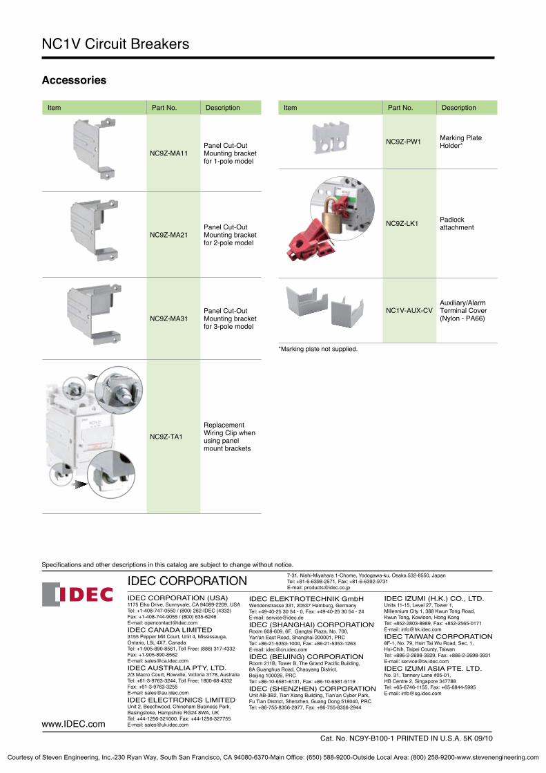
Accessories
NC1V Circuit Breakers
IDEC CORPORATION (USA)1175 Elko Drive, Sunnyvale, CA 94089-2209, USATel: +1-408-747-0550 / (800) 262-IDEC (4332) Fax: +1-408-744-9055 / (800) 635-6246E-mail: [email protected] CANADA LIMITED3155 Pepper Mill Court, Unit 4, Mississauga, Ontario, L5L 4X7, CanadaTel: +1-905-890-8561, Toll Free: (888) 317-4332 Fax: +1-905-890-8562E-mail: [email protected] AUSTRALIA PTY. LTD.2/3 Macro Court, Rowville, Victoria 3178, AustraliaTel: +61-3-9763-3244, Toll Free: 1800-68-4332Fax: +61-3-9763-3255E-mail: [email protected] ELECTRONICS LIMITEDUnit 2, Beechwood, Chineham Business Park, Basingstoke, Hampshire RG24 8WA, UKTel: +44-1256-321000, Fax: +44-1256-327755E-mail: [email protected]
7-31, Nishi-Miyahara 1-Chome, Yodogawa-ku, Osaka 532-8550, JapanTel: +81-6-6398-2571, Fax: +81-6-6392-9731E-mail: [email protected]
Specifications and other descriptions in this catalog are subject to change without notice.
Cat. No. NC9Y-B100-1 PRINTED IN U.S.A. 5K 09/10
IDEC ELEKTROTECHNIK GmbHWendenstrasse 331, 20537 Hamburg, GermanyTel: +49-40-25 30 54 - 0, Fax: +49-40-25 30 54 - 24E-mail: [email protected] (SHANGHAI) CORPORATIONRoom 608-609, 6F, Gangtai Plaza, No. 700, Yan'an East Road, Shanghai 200001, PRCTel: +86-21-5353-1000, Fax: +86-21-5353-1263E-mail: [email protected] (BEIJING) CORPORATIONRoom 211B, Tower B, The Grand Pacific Building, 8A Guanghua Road, Chaoyang District, Beijing 100026, PRCTel: +86-10-6581-6131, Fax: +86-10-6581-5119IDEC (SHENZHEN) CORPORATIONUnit AB-3B2, Tian Xiang Building, Tian’an Cyber Park, Fu Tian District, Shenzhen, Guang Dong 518040, PRCTel: +86-755-8356-2977, Fax: +86-755-8356-2944
IDEC IZUMI (H.K.) CO., LTD.Units 11-15, Level 27, Tower 1, Millennium City 1, 388 Kwun Tong Road, Kwun Tong, Kowloon, Hong KongTel: +852-2803-8989, Fax: +852-2565-0171E-mail: [email protected] TAIWAN CORPORATION8F-1, No. 79, Hsin Tai Wu Road, Sec. 1, Hsi-Chih, Taipei County, Taiwan Tel: +886-2-2698-3929, Fax: +886-2-2698-3931E-mail: [email protected] IZUMI ASIA PTE. LTD.No. 31, Tannery Lane #05-01,HB Centre 2, Singapore 347788Tel: +65-6746-1155, Fax: +65-6844-5995E-mail: [email protected]
www.IDEC.com
Item Part No. Description
NC9Z-MA11Panel Cut-Out Mounting bracket for 1-pole model
NC9Z-MA21Panel Cut-Out Mounting bracket for 2-pole model
NC9Z-MA31Panel Cut-Out Mounting bracket for 3-pole model
NC9Z-TA1Replacement Wiring Clip when using panel mount brackets
Item Part No. Description
NC9Z-PW1 Marking PlateHolder*
NC9Z-LK1 Padlock attachment
NC1V-AUX-CVAuxiliary/Alarm Terminal Cover (Nylon - PA66)
*Marking plate not supplied.
Courtesy of Steven Engineering, Inc.-230 Ryan Way, South San Francisco, CA 94080-6370-Main Office: (650) 588-9200-Outside Local Area: (800) 258-9200-www.stevenengineering.com