identification of equivalent mechanical properties for
TRANSCRIPT

Int. J. Masonry Research and Innovation Vol. XX, No. YY, 201x 1
Identification of equivalent mechanical propertiesfor unreinforced masonry walls
Christophe Mordant∗
National Fund for Scientific Research
and
Structural and Stochastic Dynamics,
University of Liège
B52/3, Quartier Polytech,
Liège 4000, Belgique
Email: [email protected]∗Corresponding author
Hervé Degée
Construction Engineering Research Group
Hasselt University
Agoralaan, Building H
Diepenbeek 3590, Belgium
Email: [email protected]
Vincent Denoël
Structural and Stochastic Dynamics,
University of Liége
B52/3, Quartier Polytech,
Liége 4000, Belgique
Email: [email protected]
Abstract: Transverse vibrations of beams are an interesting topic for numerousengineering fields. The equations of motion develop under various assumptionsand associate a frequency equation. This paper expresses the frequency equationfor two specific models, using the Timoshenko beam theory. The first model isa typical cantilever beam with an additional mass attached to the free end. Thesecond model considers a beam partially clamped at the base and with an elasticconnection of the additional mass to the free end. The relevance of the usedtheory is discussed and the importance of each term of the equation is studied.These models find applications in unreinforced masonry. They are indeedfitted to identify, from white noise tests, equivalent mechanical properties ofunreinforced load-bearing clay masonry walls including soundproofing devicesin the perspective of modelling these elements with a macro-scale approach.Discrepancies with respect to current standards are underscored.
Keywords: earthquake engineering; equivalent properties; frequency equation;Timoshenko beam theory; transverse vibrations; unreinforced masonry.
Copyright c© 201x Inderscience Enterprises Ltd.

2 C. Mordant et al.
Reference to this paper should be made as follows: Mordant, C., Degée, H.and Denoël, V. (201X) ‘Identification of equivalent mechanical properties forunreinforced masonry walls’, Int. J. Masonry Research and Innovation, Vol. XX,No. YY, pp.ZZZ–ZZZ.
Biographical notes: Christophe Mordant has been graduated as PhD in CivilEngineering at the University of Liège and at the Hasselt University in 2016.
Hervé Degée is a Professor of Structural Engineering at Hasselt University andHead of the Construction Engineering Research Group. He is also an invitedlecturer at the Universities of Ghent and Liege, where he got his PhD and usedto work as a researcher for many years. His main research field is the designand analysis of structures with a specific emphasise on the global behaviour ofstructures combining different materials, as well as earthquake engineering. Heis an active member of various standardisation commissions at the Belgian andEuropean level.
From 2001 to 2009, Vincent Denoël was a Researcher for the National ResearchFund in Belgium. He is now a Professor in Structural Engineering at theUniversity of Liège. His areas of research concern are the random dynamics oflow-dimensional systems, structural dynamics, the characterisation of dynamicactions and the numerical simulation of flexible structures and biomechanics.He teaches structural dynamics, structural design against exceptional loads,probabilities and stochastic mechanics, and perturbation methods for engineers.Vincent Denoël is also appointed as an Adjunct Professor and is a memberof the PhD Doctoral School at the University of Minnesota, where he co-supervises doctoral theses. He has collaborations with important research andindustrial partners in Europe and America. He owns a world record for thelongest deathride installed in urban area (2010) and received the ’Junior Award’of the International Association for Wind Engineering (2015).
1 Introduction
Transverse vibrations of beams have been extensively studied for a few centuries. This
interest has led to a huge number of research works. The problem is still investigated today
given its large range of applications and for two other reasons. On the one hand, several
assumptions may be formulated to project the most general equations of the theory of
elasticity onto beam, rod or elastica models (Timoshenko and Goodier, 1987). Among the
available beam theories, the well-known model proposed by Bernoulli and Euler relies on
the importance of the bending effect and results in acceptable approximations for a number
of engineering problems. Nevertheless, the model is inaccurate for the higher modes and
non-slender beams. Improvements were then introduced by Lord Rayleigh (1877), Strutt
(1877) and with the ‘shear’ model, through the integration of the rotary inertia and the
shear distortion effects of the cross section, respectively. Finally, Timoshenko (1921, 1922)
proposed a beam theory combining all these effects and giving a more adequate solution to
the problems of higher modes and non-slender beams. On the other hand, the solution of
these equations depends on the boundary conditions. The most classical ones are the ‘free-
free’, ‘clamped-clamped’, ‘hinged-hinged’ or ‘clamped-free’ ends, but other possibilities
exist, as for instance a partially clamped end. There are therefore as many solutions as
combinations of theories and boundary conditions.
Solving the differential equations of motion analytically requires the development of
the so-called frequency equation. Han et al. (1999) detailed these developments for the
Equivalent mechanical properties 3
four above-mentioned models and for the classical boundary conditions. Other authors
studied this problem with some specific details in the view of practical applications. Low
(1999, 2000) focused on the frequency analysis of an Euler-Bernoulli beam bearing a
concentrated mass at an arbitrary location and developed a modified Dunkerley formula to
approximate the exact solution with shorter computational time. Because of its increasing
use as robot arms, machines or structures, Bruch and Mitchell (1987), Oguamanam (2003),
Salarieh and Ghorashi (2006) and Ansari et al. (2011) investigated the free vibrations of
an Euler-Bernoulli or a Timoshenko cantilever beam with a rigid tip in the perspective
of studying the behaviour of a flexible member. More recent contributions dealt with
non-homogeneous or cracked beams (Li et al., 2013a; Khaji et al., 2009). The influence
of the support conditions was also considered, as for example Timoshenko beams on
Pasternak foundations (Calio and Greco, 2012) and beams on elastic end support (Li,
2013). A particular attention to forced vibrations of Timoshenko beams was given by
Majkut (2009).
Beside the study of transversally vibrating beams, a similar theoretical approach has
been used to examine the stability of beams. Several research programs have been carried
out over the past 20 years (Farchaly and Shebl, 1995; Esmailzadeh and Ohadi, 2000),
with some focused on shear beams (Zhang et al., 2013), investigating the consequences
of variable sections (Naguleswaran, 2003) or of an elastically restrained base (Hernández-
Urrea and Dario Aristizábal-Ochoa, 2008).
The present paper aims at adding another contribution to the study of transverse
vibrations of beams by determining the frequency equation of two particular cantilever
beam models, using the Timoshenko beam theory. This paper also presents a new
application of the frequency equations for the identification of equivalent mechanical
properties of unreinforced masonry (URM) structural elements. Current procedures for
the assessment of these properties are based on empirical relations between the properties
of the masonry units and joints. New building systems have been however developed
for energy efficiency coupled with economical reasons and still need to be characterised
(da Porto et al., 2009). Defining these properties for the masonry structural elements is
a primary requirement given that the full URM structures are usually modelled at the
macro-scale with the equivalent frame method (Penna et al., 2013). The use of such an
approach is widespread and provides relevant results with an interesting computational
time (Lagomarsino et al., 2013; Braga and Liberatore, 1990; Kappos et al., 2002).
In this perspective, the boundary conditions of simple cantilever beams are here
updated in order to reproduce experimental configurations of specimens tested in the
framework of the European FP7 project SERIES (Mordant et al., 2014). The specimens are
four simple load-bearing clay URM walls with thin-layer glued bed joints and a tongue-
and-groove system as head joints. They have two different aspect ratios, with a length of
2.10 m (corresponding to the ‘long walls’ here under) and 0.72 m (corresponding to the
‘short walls’ here under), respectively. An additional 5-ton steel mass is placed on the walls
and one wall of each aspect ratio includes soundproofing rubber layers located at the base
of the wall and between the wall and the additional mass (Figure 1). These specimens have
been tested on a shake table with a characterisation of their dynamic properties prior to
each shake. The geometry of the tested specimens involves the use of the Timoshenko
beam theory due to the importance of the shear deformability. Interested readers can refer
to Mordant (2016) for details about the specimens and the experimental campaign.
A first model is focused on walls without soundproofing devices and corresponds to
the classical cantilever beam with an additional mass located at the free end (Figure 2b).

4 C. Mordant et al.
A second model considers the walls with rubber layers and has to particularities due to
these latter:
i the base end is elastically restrained
ii the additional mass is not rigidly connected to the free end (Figure 2c).
Figure 1 Rubber devices used for acoustic performances (see online version for colours)
Figure 2 General sketches of (a) a cantilever beam including an additional mass and flexiblelayers, (b) model 1 and (c) model 2 (see online version for colours)
Both translational and rotational flexibilities are considered. For both models, the influence
of the additional mass is studied through
i its size (i.e. its geometry)
ii its relative magnitude referred to the mass of the wall
iii its rotary and translational inertia
iv the distance between its centroid and the beam free end (i.e. the top of the wall).
In particular, the novelty of the second model is to consider a flexible connection between
the free end and the additional mass.
Once the dimensionless frequency equations are obtained, they are used to identify
equivalent mechanical properties of the experimental specimens. This paper being focused
on the identification of the dynamic properties and not the seismic response, only
experimental results in terms of natural frequencies are useful (Mordant, 2016). During
this phase, the walls behave in the elastic range, since they are submitted to a very
low excitation. Then, the importance of the different terms of the frequency equations
is investigated. Finally, equivalent mechanical properties of the tested specimens are
identified and the results are compared to current standard recommendations.
Equivalent mechanical properties 5
2 Model description using Timoshenko beam theory
2.1 Equations of motion
The Timoshenko beam theory includes bending, shear distortion and rotary inertia effects.
Two space- and time-dependent fields describe the behaviour of the beam, namely the
transverse displacement v∗ (x∗, t∗) and the angle of rotation due to bending α (x∗, t∗).Two governing differential equations are derived from Hamilton’s variational principle
ρ∗A∗∂2v∗
∂t∗2− k′G∗A∗
(
∂2v∗
∂x∗2−
∂α
∂x∗
)
= f (x∗, t∗) (1)
ρ∗I∗∂2α
∂t∗2− EI∗
∂2α
∂x∗2− k′G∗A∗
(
∂v∗
∂x∗− α
)
= 0 (2)
where ρ∗ is the density of the beam, A∗ and I∗ are its cross-sectional area and bending
inertia, k′ is a shape factor, E and G∗ represent the elastic and shear moduli of the
beam, respectively, and f (x∗, t∗) is the transverse applied force per unit length. The used
nomenclature is taken from Han et al. (1999). This set of equations can be made non-
dimensional by introducing
x∗ref = Hw and t∗ref =1
ω∗
1
= H2w
√
ρ∗A∗
EI∗(3)
as a reference length (the length of the beam, i.e. the height of the wall in the following
application) and time (the travelling time of a bending wave along the beam), respectively.
The space and time parameters are therefore normalised as:
x =x∗
x∗ref; t =
t∗
t∗ref, (4)
while the transverse displacement of the beam is scaled as v = v∗
x∗
ref. Assuming no
transverse force per unit length and a linear elastic, isotropic and homogeneous beam with
a constant cross section, the equations of motion (1) and (2) can be decoupled. With the
dimensionless coordinates, they read
∂4v
∂x4− Ωa
∂4v
∂x2t2+∂2v
∂t2+Ω2
b
∂4v
∂t4= 0, (5)
∂4α
∂x4− Ωa
∂4α
∂x2t2+∂2α
∂t2+Ω2
b
∂4α
∂t4= 0 (6)
with the dimensionless groups
Ωa =I∗
A∗H∗2w
(
1 +E
k′G∗
)
; Ω2b =
(
I∗
A∗H∗2w
)2E
k′G∗. (7)
As the form of both differential Eqs. (5) and (6) is the same, the topology of the
unknown fields are also the same. These latter can be expressed in the frequency domain

6 C. Mordant et al.
by setting v(x, t) = φ(x)ejωt and α(x, t) = ψ(x)ejωt, with ω = ω∗
ω∗
1
the dimensionless
circular frequency and j the unit complex number. This translates the time synchronisation
of the transverse displacement and of the angle of rotation due to bending (Han et al., 1999;
Majkut, 2009). Plugging this ansatz into Eqs. (5) and (6) yields
[
φ′′′′
+Ωaω2φ
′′
− ω2φ+Ω2bω
4φ]
ejωt = 0 (8)
[
ψ′′′′
+Ωaω2ψ
′′
− ω2ψ +Ω2bω
4ψ]
ejωt = 0 (9)
where the prime symbol indicates derivatives with respect to x. These fourth-order
homogeneous result in the general solution for the mode shapes φ(x) and ψ(x)
φ = K1ez1x +K2e
z2x +K3ez3x +K4e
z4x (10)
ψ = Q1ez1x +Q2e
z2x +Q3ez3x +Q4e
z4x (11)
where
z1,2 = ±
√
√
√
√
−Ωa
2ω2 −
√
(
Ω2a
4− Ω2
b
)
ω4 + ω2 = ∓a (12)
z3,4 =
√
√
√
ñ
[
Ωa
2ω2 −
√
(
Ω2a
4− Ω2
b
)
ω4 + ω2
]
=
b
b(13)
are the roots of the characteristic polynomial. The variables a, b and b are the dimensionless
wave numbers.
Finally, Eqs. (10) and (11) can be turned into trigonometric or hyperbolic expressions.
Two pairs of solutions are derived from (10) and (11) since z3 and z4 are either real or
imaginary, depending on the circular frequency ω with respect to the critical frequency
ωc = Ω−1b . When the circular frequency is smaller than the critical frequency (ωΩb ≤ 1),
the spatial (wave) solutions are expressed by:
φ = C1 sin ax+ C2 cos ax+ C3 sinh bx+ C4 cosh bx, (14)
ψ = D1 sin ax+D2 cos ax+D3 sinh bx+D4 cosh bx. (15)
On the contrary, when the angular frequency is larger than the critical frequency (ωΩb ≥ 1),
the solutions read
φ = C1 sin ax+ C2 cos ax+ C3 sin bx+ C4 cos bx, (16)
ψ = D1 sin ax+ D2 cos ax+ D3 sin bx+ D4 cos bx. (17)
The parameters C1, C2, C3, C4 and D1, D2, D3, D4 (resp. C1,· · · , C4 and D1,· · · , D4)
in Eqs. (14) and (15) (resp. (16) and (17)) are eight coefficients to be determined to satisfy

Equivalent mechanical properties 7
the boundary conditions. These coefficients can however be reduced to four as explained
by Han et al. (1999), observing that they are related by
D1 = −ϕaC2D2 = ϕaC1(18)
D3 = ϕbC4D4 = ϕbC3
and
D1 = −ϕaC2D2 = ϕaC1(19)
D3 = −ϕbC4D4 = ϕbC3
with ϕa = a2+γ2b2
(1+γ2)a , ϕb =b2+γ2a2
(1+γ2)b , ϕa = a2−γ2b2
(1+γ2)a , ϕb =b2−γ2ba2
(1+γ2)b and γ = Ek′G∗
=2(1+ν)
k′.
Once the boundary conditions specified, this yields four relations between the four
unknown coefficients C1,· · · , C4 (C1,· · · , C4, respectively, if ωΩb ≥ 1) which can be
expressed as a matrix. The frequency equation is then obtained by setting the determinant
of this matrix to zero, avoiding the trivial solution corresponding to zero coefficients, and
revealing therefore the natural frequencies of the considered problem.
2.2 Models and boundary conditions
Two models of a cantilever beam are considered herein with specific details. The first
model has an additional mass rigidly connected to the free end of the beam, as shown in
Figure 2b. The second model is sketched in Figure 2c and differs from the first one due
to a partially clamped bottom end and to an elastic connection of the additional mass to
the free end. In the applications considered below, these peculiarities are the consequences
of flexible elements located at the beam ends and modelled by rotational and translational
springs. In both models, the additional mass weighs m∗ [kg] and possesses a rotary inertia
I∗cin [kg.m2]. Moreover, the centroid of the mass is at a distanceH∗
b [m] from the tip end of
the beam. The springs defining the partially clamped end are characterised by a stiffness in
rotationK∗
r,b and in translationK∗
t,b, whileK∗
r,t andK∗
t,t are the stiffness in rotation and in
translation of the springs representing the flexible connection of the additional mass to the
free end. These parameters are scaled in the same manner as above, leading to the following
dimensionless quantities m =m∗ω∗
2
1H3
w
EI∗, Icin =
I∗
cinω∗2
1Hw
EI∗, Hb =
H∗
b
Hw, Kr,b = K∗
r,bH3
w
EI∗,
Kt,b = K∗
t,bHw
EI∗, Kr,t = K∗
r,tH3
w
EI∗and Kt,t = K∗
t,tHw
EI∗.
Details of the beam top with the additional mass are depicted in Figure 3, showing the
contributions of the bending (blue) and shear (red) effects in terms of angle of rotations.
The usual simplification for the shear deformation is given in Figure 3b. Under bending
and shear effects, the centroid of the additional mass is subjected to a rotation α with
respect to the x-axis. The angle γ, representing the shear effects, only impacts the variation
of the transverse displacement along the height. This observation will be useful for the
formulations of the bending moment and shear force.
To be consistent with the Timoshenko beam theory described above, a homogeneous
beam with a linear and indefinitely elastic material and a doubly symmetric cross section is
assumed. The consequences of the specific details are practically translated by modifying

8 C. Mordant et al.
Figure 3 Details of the model free end (see online version for colours)
the boundary conditions of the classical cantilever beam. These latter are here expressed in
a dimensionless form for the clamped (x = 0) and free (x = 1) ends, respectively,
v = 0 ; α = 0 at x = 0 (20)
M = −α′ = 0 ; V = k′GA (v′ − α) = 0 at x = 1 (21)
with G = G∗H4w/EI
∗, A = A∗/H2w and M (x, t) and V (x, t) representing the
dimensionless bending moment and shear force, defined as
M =M∗
M∗
ref
and V =V ∗
V ∗
ref
(22)
where M∗ (x∗, t∗) and V ∗ (x∗, t∗) are the bending moment and the shear force and
M∗
ref =EI∗
Hw
and V ∗
ref =EI∗
H2w
(23)
2.2.1 First model
In the first model, the additional mass only influences the conditions at the free end (x = 1),
involving non-zero bending moment and shear force
M = −α′ = mHb (v +Hbα) + Icinα
V = k′GA (v′ − α) = −m[
v +Hbα−Hbv′ −H2
b α′]
+ Icinα′ (24)
The magnitude m and inertia Icin of the mass as well as the distance Hb are identified as
the three main parameters characterising the influence of the additional mass. The prime
and dot symbol indicate derivatives with respect to x and t, respectively.

Equivalent mechanical properties 9
2.2.2 Second model
In addition to the mass, the presence of flexible devices in the second model affects the
boundary conditions at both ends. On the one hand, the beam base (x = 0) cannot be
considered as clamped anymore. A rotation and a transverse displacement are allowed and
their magnitude depends on the stiffness of the springs
v =V
Kt,b
=k′GA
Kt,b
(v′ − α) ;α = −M
Kr,b
=α′
Kr,b
. (25)
On the other hand, a relative rotation α and a relative displacement v are possible
between the top of the beam and the base of the additional mass due to the elastic
connection. These contributions have to be taken into account and lead to the boundary
conditions at the free end (x = 1)
M = −α′
= mHb
[
v + v +Hb (α+α)]
+ Icin (α+α)
= mHb (v +Hbα) +mHb
[
k′GA
Kt,t
(v′ − α) +Hbα
′
Kr,t
]
+ Icin
(
α+α′
Kr,t
)
V = k′GA (v′ − α)
= −m [v +v +Hb (α+α)] +mHb (v′ +v′ +Hbα
′ +Hbα′)
+ Icin (α′ +α′) (26)
= −m (v +Hbα)−m
[
k′GA
Kt,t
(v′ − α) +Hbα
′
Kr,t
]
+mHb (v′ +Hbα
′)
+mHb
[
k′GA
Kt,t
(v′′ − α′) +Hbα
′′
Kr,t
]
+ Icin
(
α′ +α′′
Kr,t
)
Equations (24)–(26) neglect the second-order effects and the influence of the gravity is
hence not considered.
3 Frequency equations
The frequency equations are established for the case of a circular frequency lower than the
critical frequency (ωΩb ≤ 1). The equations for a circular frequency larger than the critical
one can be obtained by replacing b with jb.
3.1 Frequency equation of the first model
Equations (20) and (24) provide some relations between the four unknown coefficients, see
(14). These relations are written in a matrix form as:
Ac :=
0 1 0 1ϕa 0 ϕb 0A31 A32 A33 A34
A41 A42 A43 A44
C1
C2
C3
C4
= 0 (27)

10 C. Mordant et al.
where c is the vector gathering the integration constants of the mode shapes φ(x) and ψ(x).In matrix A, we have introduced
A31 =(
aϕa + P)
sin a+ ϕaQ cos a
A32 =(
aϕa + P)
cos a− ϕaQ sin a
A33 = −(
bϕb − P)
sinh b+ ϕbQ cosh b
A34 = −(
bϕb − P)
cosh b+ ϕbQ sinh b
A41 = (a− ϕa)
(
1 +P
k′GA
)
cos a−
(
ω2m
k′GA+
aϕa
k′GAQ
)
sin a (28)
A42 = − (a− ϕa)
(
1 +P
k′GA
)
sin a−
(
ω2m
k′GA+
aϕa
k′GAQ
)
cos a
A43 = (b− ϕb)
(
1 +P
k′GA
)
cosh b−
(
ω2m
k′GA−
bϕb
k′GAQ
)
sinh b
A44 = (b− ϕb)
(
1 +P
k′GA
)
sinh b−
(
ω2m
k′GA−
bϕb
k′GAQ
)
cosh b
where
Q = ω2(
mH2b + Icin
)
; P = ω2mHb. (29)
Setting the determinant of the matrix A to zero leads to the frequency equation. This
equation needs to be solved for ω which lies in a, b, Q andP .
3.2 Frequency equation of the second model
In the second model, based on Eqs. (25) and (26), the frequency equation reads
Ac :=
A11 1 A13 1
ϕa A22 ϕb A24
A31 A32 A33 A34
A41 A42 A43 A44
C1
C2
C3
C4
= 0 (30)
where
A11 = −k′GA
Kt,b
(a− ϕa)
A13 = −k′GA
Kt,b
(b− ϕb)
A22 =aϕa
Kr,b
A24 = −bϕb
Kr,b
A31 = A31 −aϕa
Kr,t
Q sin a+k′GA
Kt,t
(a− ϕa) P cos a

Equivalent mechanical properties 11
A32 = A32 −aϕa
Kr,t
Q cos a−k′GA
Kt,t
(a− ϕa) P sin a
A33 = A33 +bϕb
Kr,t
Q sinh b+k′GA
Kt,t
(b− ϕb) P cosh b (31)
A34 = A34 +bϕb
Kr,t
Q cosh b+k′GA
Kt,t
(b− ϕb) P sinh b
A41 = A41 −aϕa
k′GAKr,t
[
aQ cos a− P sin a]
−(a− ϕa)
Kt,t
[
ω2m cos a+ aP sin a]
A42 = A42 +aϕa
k′GAKr,t
[
aQ sin a+ P cos a]
+(a− ϕa)
Kt,t
[
ω2m sin a− aP cos a]
A43 = A43 +bϕb
k′GAKr,t
[
bQ cosh b− P sinh b]
+(b− ϕb)
Kt,t
[
ω2m cosh b+ bP sinh b]
A44 = A44 +bϕb
k′GAKr,t
[
bQ sinh b− P cosh b]
+(b− ϕb)
Kt,t
[
ω2m sinh b+ bP cosh b]
It can be noticed that this second case degenerates into the first model if the stiffnesses
Kt,t, Kr,t, Kt,b, Kr,b tend to infinity.
4 Parametric study of the beam models, frequency equations and mode
shapes
The coefficients of the matrix A, leading to the expression of the frequency equation,
highlight the importance of the geometrical and mechanical properties of the beam through
the dimensionless groups Ωa and Ωb. Additional parameters also influence this equation
due to the presence of an additional mass at the top, such as the mass m and its rotary
inertia Icin as well as the distance Hb from the beam free end to the centroid of the mass.
The second model has four extra parameters. These are the stiffnesses in rotation and in
translation of the material placed at the beam ends, namely (Kr,b, Kt,b) and (Kr,t, Kt,t)
for the base and top ends, respectively. In comparison with the classical cantilever beam,
those parameters obviously add complexity in the frequency equation.
4.1 Comparison of the Euler-Bernoulli and Timoshenko beam models
Equations (5) and (6) express the decoupled equations of motion according to the
Timoshenko beam theory. When Ωa ≪ 1 and Ωb ≪ 1, these equations regularly
degenerate into the equation of motion given by the Euler-Bernoulli (E-B) theory. This
section aims at studying the evolution of the wave numbers a and b (or b) as a function
of the dimensionless groups Ωa and Ωb. The variations of these latter are correlated in the
light of the expressions of the wave numbers given in (12) and (13). Indeed, the radicand
of these equations has to be positive, leading to the condition
Ω2b −
Ω2a
4≤
1
ω2. (32)
Figure 4 gives a mapping of the wave numbers a and b (or b), respectively, for a
dimensionless circular frequency ω equal to unity. It shows white areas which correspond

12 C. Mordant et al.
to couples[
Ωa; Ω2b
]
not complying with the condition (32). Setting the dimensionless
groups Ωa and Ωb to zero provides identical and unit wave numbers (a = b = 1). It
corresponds to the E-B beam theory. In the Timoshenko beam theory, these groups
are however non-zero. Considering the specimens without rubber described by Mordant
(2016) and the mechanical properties as recommended in the Eurocodes, namely E =1000fk and G∗ = 0.4E, we obtain
Figure 4 Influence of Ωa and Ωb on wave numbers a and b (or b) (see online version for colours)
Ωa = 0.0489 ; Ω2b = 4.4819× 10⁻⁴
for the short wall and
Ωa = 0.4159 ; Ω2b = 0.0324
for the long one. These couples of values are represented in Figure 4 with red and green
points, respectively. The wave numbers are a = 0.9888 and b = 0.9885 for the short wall,
while the wave numbers for the long wall are a = 0.8901 and b = 0.8708. Consequently,
an E-B model is sufficient to model the short wall, whereas a Timoshenko beam is required
for the long wall.
4.2 Parameters related to the additional upper mass
Figure 5 plots the dimensionless frequency equation of the first model considering the
material and geometrical properties of the short wall given in Mordant (2016). The values
of the parameters related to the mass are also derived from the quantities given in this
reference. The mechanical properties of the masonry are chosen according to the Eurocodes
recommendations. These choices result in Ωa = 0.0489 and Ω2b = 4.4819× 10⁻⁴. Several
variations around this nominal configuration are represented:
i no additional mass (yellow)

Equivalent mechanical properties 13
ii an upper mass without gap Hb between the beam end and the centroid of the mass
(green)
iii an additional mass without rotary inertia Icin (red)
iv a combination of (ii) and (iii) (black).
Figure 5 Frequency equation with different assumptions (first model) - short wall without rubber(see online version for colours)
Figure 6 gives the same results in the case of the long wall, whose nominal configuration
is characterised by Ωa = 0.4159 and Ω2b = 0.0324. Beside the solid curves representing
the Timoshenko model, dashed lines with similar colours represent the frequency
equations obtained by the E-B beam theory (i.e. enforcing Ωa = Ω2b = 0) under the same
assumptions.
Comparison of the different curves in Figures 5 and 6 shows the importance of the
additional mass. This latter indeed provides more than 90% of the total mass and involves
Figure 6 Frequency equation with different assumptions (first model) - long wall without rubber(see online version for colours)

14 C. Mordant et al.
a large decrease of the first circular frequency of the beam. The influence of the gapHb and
the rotary inertia Icin is more important for the short wall than for the long one. Numerical
values are given in Table 1. The variation is effectively higher for the short wall (from
5.3 to 16.2%), whereas it is less significant for the long one (less than 4.9%). Therefore,
the contribution of the rotary inertia and the distance between the top of the wall and the
centroid of the mass has to be considered, especially for the short wall.
Figures 5 and 6 also compare the frequency equations developed when considering
E-B (dashed lines) and Timoshenko (solid lines) beam theories. The fundamental circular
frequencies for both theories are also tabulated in Table 1. Under the assumptions (ii)–(iv),
the relative difference between both theories is lower than 5% regarding the short wall.
This difference ranges between 19 and 30% in the case of the long wall. These values show
that the E-B model can be sufficient for the short wall, but that the Timoshenko model is
necessary for the long wall, as already observed from the graphical representations. The E-
B theory with assumption (i) leads to the same result for both walls. This comes from the
non-dimensional formalism defined in Section 2.
Table 1 Fundamental circular frequency with different assumptions (first model) - numericalvalues
Wall Full m = 0 Hb = 0 Icin = 0 Hb = Icin = 0
(i) (ii) (iii) (iv)
Short (Timoshenko) 0.2513 3.1820 0.2648 0.2718 0.2918
Short (Euler-Bernoulli) 0.2579 3.5160 0.2737 0.2829 0.3075
Long (Timoshenko) 0.3560 2.1254 0.3614 0.3660 0.3735
Long (Euler-Bernoulli) 0.4383 3.5160 0.4649 0.4803 0.5215
Regarding the frequency equation obtained with the Timoshenko theory, further studies
on the influence of the different parameters related to the mass have been performed. The
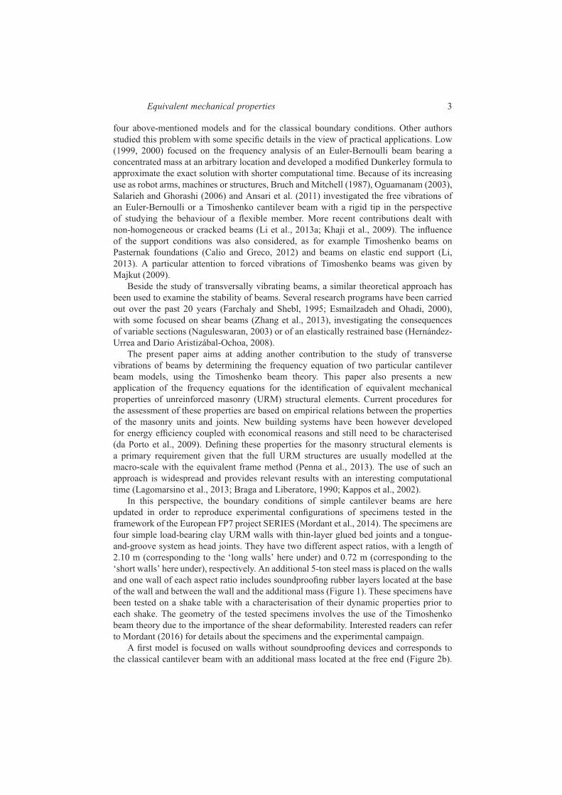
results are given in Figure 7. The influence of the magnitude of the additional mass (top),
of the gap Hb (middle) and of the rotary inertia Icin (bottom) are given for the short (in
blue) and long (in red) walls. The results are in accordance with the values tabulated in
Table 1. For example, values obtained under the assumption of no additional mass (i) or
Hb = 0 (ii) correspond to the intersection of the curves in Figure 7 (top and middle) with
the x-axis. Figure 7 (bottom) provides the tabulated values with Icin = 0 (assumption (iii))
when the ordinate is equal to −1. Again, Figure 7 highlights the higher importance of the
parameters in the case of the short wall. Additional observations can be made: first, the first
circular frequency is very sensitive to variations of the additional mass. The interpretation
of these results has to be carefully done because the specimen total mass varies and any
increment of mass has also consequences on the rotary inertia. Second, the rotary inertia
Icin seems to have the lowest influence on the frequency equation, especially for the long
wall.
Equivalent mechanical properties 15
Figure 7 Influence of the parameters related to the mass: (a) Influence of the additional mass atthe top, (b) influence of the distance between the top of the wall and the centroid of themass, (c) influence of the rotary inertia of the mass (see online version for colours)
4.3 Parameters related to the stiffness of the base and of the mass-beam
connection
The influence and importance of the presence of rubber layers leading to a beam with an
elastically restrained bottom end and an additional mass elastically connected to the top is
studied by comparing the frequency equation obtained with the assumption of
i a cantilever beam with an additional mass rigidly connected to its free end (first
model case)
ii the same beam with an elastically restrained base
iii the same beam with a mass elastically connected to the top
iv the beam combining the effects of (ii) and (iii).
The material and geometrical properties are those of the short and long walls given
by Mordant (2016). The parameters related to the additional mass are based on the
quantities given in the same reference. The couple of mechanical characteristic of the
rubber (E∗
rubber, G∗
rubber) are chosen in the range of usual values and but are the same for
the bottom and top ends. The frequency equations are re-normalised with the same circular
frequency than the first model, since the beam is the same.
The results are given in Figure 8 (short wall) and Figure 9 (long wall) and the
comparison is summarised in Table 2 with several observations.
The effect of the rubber layers on the natural frequency is more or less the same for both
walls with a decrease in the fundamental circular frequency around 75%. This conclusion
is mitigated when there is only the elastically connected mass (column 3) given that the
decrease is about 45% for the short wall and 63% for the long wall. Both rubber layers
influence the results, even if placing a rubber layer at the bottom end only (column 4)
leads to a larger decrease. Indeed, Table 2 highlights that adding the soundproofing layer
between the top of the wall and the additional mass in the presence of a layer located at the

16 C. Mordant et al.
Figure 8 Influence of the stiffness of the base and stiffness of the mass-to-wall connection(second model) - short wall with rubber (see online version for colours)
base of the wall does not involve a significant drop. Therefore, it can be concluded that the
bottom rubber layer has more influence on the frequency drop. The decreases produced by
the two rubber layers are not additive.
Figure 9 Influence of the stiffness of the base and stiffness of the mass-to-wall connection(second model) - long wall with rubber (see online version for colours)
Table 2 Fundamental circular frequency with different assumptions (second model) -numerical value
Wall Without rubber With rubber 1/Kr,b = 1/Kt,b = 0 1/Kr,t = 1/Kt,t = 0
Short 0.2513 0.0600 0.1336 0.0652
Long 0.3561 0.0761 0.1311 0.0906
Equivalent mechanical properties 17
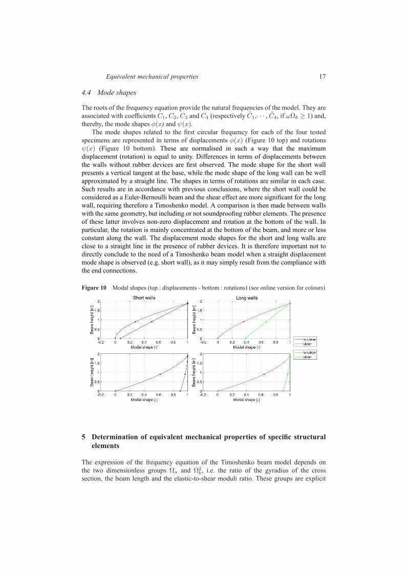
4.4 Mode shapes
The roots of the frequency equation provide the natural frequencies of the model. They are
associated with coefficients C1, C2, C3 and C4 (respectively C1,· · · , C4, if ωΩb ≥ 1) and,
thereby, the mode shapes φ(x) and ψ(x).The mode shapes related to the first circular frequency for each of the four tested
specimens are represented in terms of displacements φ(x) (Figure 10 top) and rotations
ψ(x) (Figure 10 bottom). These are normalised in such a way that the maximum
displacement (rotation) is equal to unity. Differences in terms of displacements between
the walls without rubber devices are first observed. The mode shape for the short wall
presents a vertical tangent at the base, while the mode shape of the long wall can be well
approximated by a straight line. The shapes in terms of rotations are similar in each case.
Such results are in accordance with previous conclusions, where the short wall could be
considered as a Euler-Bernoulli beam and the shear effect are more significant for the long
wall, requiring therefore a Timoshenko model. A comparison is then made between walls
with the same geometry, but including or not soundproofing rubber elements. The presence
of these latter involves non-zero displacement and rotation at the bottom of the wall. In
particular, the rotation is mainly concentrated at the bottom of the beam, and more or less
constant along the wall. The displacement mode shapes for the short and long walls are
close to a straight line in the presence of rubber devices. It is therefore important not to
directly conclude to the need of a Timoshenko beam model when a straight displacement
mode shape is observed (e.g. short wall), as it may simply result from the compliance with
the end connections.
Figure 10 Modal shapes (top : displacements - bottom : rotations) (see online version for colours)
5 Determination of equivalent mechanical properties of specific structural
elements
The expression of the frequency equation of the Timoshenko beam model depends on
the two dimensionless groups Ωa and Ω2b , i.e. the ratio of the gyradius of the cross
section, the beam length and the elastic-to-shear moduli ratio. These groups are explicit

18 C. Mordant et al.
in the governing equations and implicit in the waves numbers a, b and b. In the present
contribution, other parameters also play an important role in the model, like the mass
and the geometry of the additional mass (m, Hb and Icin) or stiffness’s involved in
the boundary conditions Kr,b, Kt,b, Kr,t and Kt,t. The determination of some of these
parameters is straightforward, especially for geometrical ones. Regarding URM structures,
others are more difficult to assess because of the heterogeneity of the material (units +
mortar) and the large range of masonry types (clay or concrete units with mortar, glued or
empty joints, etc.).
In the perspective of modelling the URM structural elements with equivalent
homogeneous and isotropic beam elements at a macro-scale (equivalent frame model),
the use of the frequency equation to determine equivalent mechanical properties becomes
relevant. Indeed, the establishment of this equation is based on a beam model with
assumptions on the material similar to what is used in equivalent beam models. Usual
possible ways to estimate the mechanical properties of such elements are the execution
of tests according, for instance, to EN 1052-1 or the use of empirical formulae. These
latter are however derived from experimental tests and cannot cope with the specificities
of every type of masonry. In the experimental campaign used as main reference for the
present contribution, tests on wallets according to EN 1052-1 have been carried out prior
to the dynamic testing by the producer of the masonry units to evaluate the strength of the
masonry but however without including the characterisation of the elastic modulus.
In the following, the frequency equations are used to determine the fundamental
frequency of URM walls without soundproofing devices prior to the shakes. This frequency
is equal to 9.33 Hz and 4.02 Hz for the long and short walls respectively. Due to the lack
of characterisation of the elastic and shear moduli of the masonry, recommendations of the
Eurocodes are first considered. Then, a parametric study is carried out in order to define
the couples of equivalent mechanical properties leading to the undamaged fundamental
frequency obtained by the experiments. Finally, the more relevant couple (E,G∗) is used
as an input for the frequency equation related to walls including rubber and a parametric
study is developed to identify equivalent mechanical properties of the rubber.
5.1 Fundamental frequency using standard recommendations
EN-1996-1-1 advises that (Section 3.7.2.(2)) “In the absence of a value determined by tests
in accordance with EN 1052-1, the short-term secant modulus of elasticity of masonry, E,
for the use in structural analysis, may be taken to be KEfk” and recommends the value
of 1000 for KE . Notice that the value of KE is not divided by 2 to take into account
cracking, as suggested by EN 1998-1 for seismic analysis of URM structures, because
the used experimental results correspond to an undamaged configuration. EN 1996-1-1
also defines the shear modulus G∗ as 40% of the elastic modulus E (Section 3.7.3.(1)). It
follows,
E = 3900MPa; G∗ = 1560MPa. (33)
Substituting these values in the frequency equation corresponding to the simple URM walls
provides the fundamental frequencies tabulated in Table 3. Comparing these results with
the values obtained from the experiments shows a relative difference of 54.71 and 20.24%
for the long and short walls, respectively. The recommendations of the Eurocodes lead
therefore to an overestimation of the mechanical parameters in the case of URM with thin

Equivalent mechanical properties 19
bed-layered joints using a tongue-and-groove system for the head joints. The discrepancy
can either come from the assessment of the elastic modulus or from the ratio between the
shear and elastic moduli G∗/E. In the case of masonry with empty vertical joints, the
definition of a unique ratio for the estimation of the shear modulus independently from the
length of the wall is quite surprising. Indeed, the number of joints increases with the length
of the wall and a higher deformability in shear could be expected.
Table 3 Fundamental frequency of URM walls without rubber using the standardsrecommendations
Long wall Short wall
Frequency [Hz] 20.82 5.04
Dimensionless frequency [-] 0.057 0.040
5.2 Characterisation of the masonry mechanical properties
Based on the observations in the previous section, a parametric study is performed with
the aim of identifying the couples (E,G∗) that should be used in the frequency equation in
order to recover the eigenfrequencies measured experimentally. Instead of adjusting E and
G∗ separately, we take the advantage of the fact that the ratioG∗/E usually lies in a specific
range. We will therefore identify two parameters, namely the elastic modulus E and the
ratio G∗/E by constraining this identification problem to a unique Young’s modulus for
both long and short walls. This constraint stems from the fact that walls are built using the
same masonry. The vertical empty joints should thus not influence the bending behaviour
and, consequently, the value of the equivalent elastic modulus.
Figure 11 plots the results of this analysis for the long and short walls without rubber.
The blue and red lines are the lieu of the pairs (E,G∗/E) providing, with the Timoshenko
beam model, the same fundamental frequency as that identified from the experiments for
the long and short walls, respectively.
Figure 11 Characterisation of the masonry mechanical properties

20 C. Mordant et al.
Comparison of the curves in Figure 11 highlights a higher dependency to the G∗/E ratio
of the long wall because its curve shows a more important increase in the elastic modulus
when G∗/E ratio decreases, at least for E & 800 MPa. Such a sensitivity is intuitively
expected, when considering the ratio between the bending and shear deformabilities of the
walls. Indeed, the influence of the latter becomes as important as the former in the case of
the long wal, since they are of the same order of magnitude (Table 4).
This statement is further emphasised in Figures 12 and 13. Figure 12 effectively
illustrates the high dependency to the G∗/E ratio of the results for the long wall, since the
curves differ while they are clearly similar for the short wall (Figure 13).
Table 4 Bending and shear deformabilities of masonry walls
Bending deformability [m/N] Shear deformability [m/N]
Long wall 9.360710−9 9.555710−9
Short wall 2.322610−7 2.787110−8
Figure 12 Dependence to the shear deformability (long wall) (see online version for colours)
Considering the constraint on the equivalent Young’s modulus, this one is identified as
ranging from 2400 to 4000 MPa (see black arrow in Figure 11). For the short wall, it is
most likely around 2450 MPa which agrees with a G∗/E ratio between 1 and 1/3. For the
long wall, this leads to G∗/E ratio lower than 0.1. The considered limits on the interval
[1/3; 1] for the G∗/E ratio correspond to the classical limitation of the Poisson’s ratio.
This ratio relates the elastic and shear moduli and can vary from −1 to 0.5 for a continuous
material. However, such assumption is questionable in the case of masonry with empty
vertical joints and the G∗/E ratio may become lower than 1/3 (Poisson’s ratio virtually
larger than 0.5). This range of values is also observable for other materials (Lee and Lakes,
1997). Moreover, contrary to the bending deformability, the shear deformability might
suffer from size effects (i.e. number of vertical open joints), which are not accounted for
Equivalent mechanical properties 21
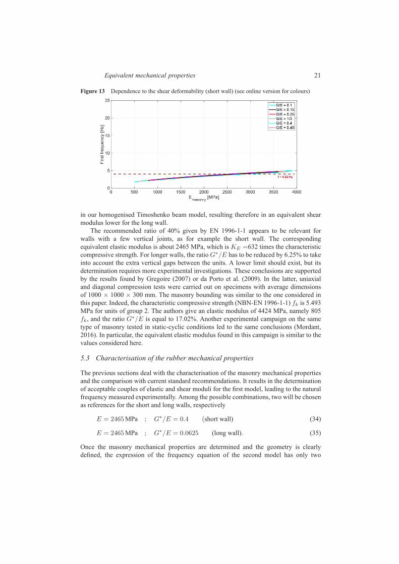
Figure 13 Dependence to the shear deformability (short wall) (see online version for colours)
in our homogenised Timoshenko beam model, resulting therefore in an equivalent shear
modulus lower for the long wall.
The recommended ratio of 40% given by EN 1996-1-1 appears to be relevant for
walls with a few vertical joints, as for example the short wall. The corresponding
equivalent elastic modulus is about 2465 MPa, which is KE =632 times the characteristic
compressive strength. For longer walls, the ratio G∗/E has to be reduced by 6.25% to take
into account the extra vertical gaps between the units. A lower limit should exist, but its
determination requires more experimental investigations. These conclusions are supported
by the results found by Gregoire (2007) or da Porto et al. (2009). In the latter, uniaxial
and diagonal compression tests were carried out on specimens with average dimensions
of 1000 × 1000 × 300 mm. The masonry bounding was similar to the one considered in
this paper. Indeed, the characteristic compressive strength (NBN-EN 1996-1-1) fk is 5.493
MPa for units of group 2. The authors give an elastic modulus of 4424 MPa, namely 805
fk, and the ratio G∗/E is equal to 17.02%. Another experimental campaign on the same
type of masonry tested in static-cyclic conditions led to the same conclusions (Mordant,
2016). In particular, the equivalent elastic modulus found in this campaign is similar to the
values considered here.
5.3 Characterisation of the rubber mechanical properties
The previous sections deal with the characterisation of the masonry mechanical properties
and the comparison with current standard recommendations. It results in the determination
of acceptable couples of elastic and shear moduli for the first model, leading to the natural
frequency measured experimentally. Among the possible combinations, two will be chosen
as references for the short and long walls, respectively
E = 2465MPa ; G∗/E = 0.4 (short wall) (34)
E = 2465MPa ; G∗/E = 0.0625 (long wall). (35)
Once the masonry mechanical properties are determined and the geometry is clearly
defined, the expression of the frequency equation of the second model has only two

22 C. Mordant et al.
unknowns left, namely the mechanical properties of the rubber layers, placed at the base
of the wall and between the top of the wall and the additional mass. These properties are
translated via the values of the stiffnessesKr,b,Kt,b,Kr,t andKt,t present in the frequency
equation.
The results presented in Figure 14 provide the coupled values (E∗
rubber, G∗
rubber/E∗
rubber) giving the first natural frequency measured experimentally. The mechanical
properties of the rubber layers are the same for the top and bottom as the same material is
used. Contrary to the masonry wall, the rubber layers can be considered as a homogeneous
and continuous body. There is therefore a relation between the elastic and shear moduli
through Poisson ratio
G∗
rubber =E∗
rubber
2(1 + νrubber). (36)
For rubber elements, the Poisson’s ratio is close to the incompressibility limit ν = 0.5 and
leads to a G∗
rubber/E∗
rubber ratio of 1/3. The corresponding elastic modulus is 11.1 MPa
for the short wall and 7.5 MPa for the long one. The long wall also exhibits a greater
dependency on the Poisson’s ratio in comparison to short wall (see Figure 14).
Figure 14 Characterisation of the mechanical properties of the rubber layers
These results are in accordance with the experimental measurements and the producer’s
prescriptions (Mordant, 2016). The difference between the identified values (11.1 and
7.5 MPa) has several causes. On the one hand, the rubber layer works under different
compressive stresses for the short and long walls. It is well known that the rubber exhibits
a lower deformability under a larger stress, hence the rubber placed at the extremities of
the short wall has a larger elastic modulus. On the other hand, the mechanical properties
of the rubber devices show some significant variability due to their manufacturing process,
i.e. they are made of recycled rubber, involving a possible scatter in the properties.
6 Conclusion
This paper is dedicated to the development of the frequency equation of a modified
cantilever beam, using the Timoshenko beam theory. Two models are studied to consider

Equivalent mechanical properties 23
the modifications of the classic cantilever beam. The first model consists in a classical
cantilever beam with an additional mass rigidly connected to the free end. The second
one includes an elastically restrained base and a flexible connection between the free end
and the additional mass. These modifications are taken into account through a proper
modification of the boundary conditions. The deduced frequency equations highlight the
importance the dimensionless groups Ωa and Ω2b which include the geometrical and
mechanical parameters of the beam as well as the stiffness of the base and mass-to-beam
connections. Then, the frequency equations are used to characterise equivalent mechanical
properties of load-bearing clay URM walls including soundproofing devices. Tested on a
shaking table, these walls have glued horizontal joints and empty vertical ones. Rubber
layers are placed at their base and top for acoustic performance reasons. One of the main
outcomes of the experimental tests is the assessment of the natural frequencies of the walls,
based on the measurements of accelerations during white noise identification tests. For the
first model, the characterisation leads to the definition of combined values for equivalent
elastic and shear moduli of the masonry walls, E and G∗, expressed by the combination of
the elastic modulus E and theG∗/E ratio. The second model is focused on the mechanical
properties of the soundproofing devices. Finally, a comparison of the results in terms
of mechanical properties with current standard recommendations for masonry structures
shows an overestimation of the recommended values for the considered type of masonry.
This paper however proves that the modelling of masonry walls thanks to equivalent beam
using the Timoshenko beam theory is possible.
Acknowledgements
The research leading to these results has received funding from the European Union
Seventh Framework Program (FP7/2007–2013) under grant agreement n 227887,
SERIES. The authors acknowledge the support received from the EQUALS laboratory
and the University of Bristol for the access to their facilities and their help during the
experimental campaign. C. Mordant also acknowledges the direct support received from
F.R.I.A. (F.R.S.-FNRS - Belgian Fund for Scientific Research).
References
Ansari, M., Jalili, N. and Esmailzadeh, E. (2011) ‘Exact frequency analysis of a rotating cantileverbeam with tip mass subjected to torsional-bending vibrations’, Journal of Vibration andAcoustics, Vol. 133, No. 4, p.041003.
Braga, F. and Liberatore D. (1990) ‘A finite element for the analysis of the response of masonrybuildings’, Proceedings of 5th North American masonry conference. University of Illinois atUrbana-Champaign, 3–6 June.
Bruch Jr, J.C. and Mitchell, T.P. (1987) ‘Vibrations of a mass-loaded clamped-free Timoshenkobeam’, Journal of Sound and Vibration, Vol. 114, No. 2, pp.341–345.
Calio, I. and Greco, A. (2012) ‘Free vibrations of Timoshenko beam-columns on Pasternakfoundations’, Journal of Vibration and Control, Vol. 19, No. 5, pp.686–696. doi:10.1177/1077546311433609. http://jvc.sagepub.com/cgi/doi/10.1177/1077546311433609
da Porto, F., Grendene, M. and Modena, C. (2009) ‘Estimation of load reduction factors forclay masonry walls’, Earthquake Engineering & Structural Dynamics, Vol. 38, No. 10,pp.1155–1174. doi:10.1002/eqe.887. http://doi.wiley.com/10.1002/eqe.887
24 C. Mordant et al.
Esmailzadeh, E. and Ohadi, A.R. (2000) ‘Vibration and stability analysis of non-uniformTimoshenko beams under axial and distributed tangential loads’, Journal of Sound andVibration, Vol. 236, No. 3, pp.443–456. doi:10.1006/jsvi.2000.2999. http://linkinghub.elsevier.com/retrieve/pii/S0022460X00929997
Farchaly, S. and Shebl, M. (1995) ‘Exact frequency and mode shape formulae for studyingvibration and stability of Timoshenko beam system’, Journal of Sound and Vibration, Vol. 180,pp.205–227. http://www.sciencedirect.com/science/article/pii/S0022460X85700752
Gregoire, Y. (2007) ‘Compressive strength of masonry according to eurocode 6: a contribution to thestudy of the influence of shape factors’, Masonry International, Vol. 20, No. 2, p.69.
Han, S., Benaroya, H. and Wei, T. (1999) ‘Dynamics of transversely vibrating beamsusing four engineering theories’, Journal of Sound and Vibration, Vol. 225, pp.935–988.http://www.sciencedirect.com/science/article/pii/S0022460X99922575
Hernández-Urrea, J. and Dario Aristizábal-Ochoa, J. (2008) ‘Static and dynamic stability of anelastically restrained Beck column with an attached end mass’, Journal of Sound and Vibration,Vol. 312, Nos. 4–5, pp.789–800. doi:10.1016/j.jsv.2007.11.014. http://linkinghub.elsevier.com/retrieve/pii/S0022460X0700908X
Lagomarsino, S., Penna, A., Galasco, A. and Cattari, S. (2013) ‘Tremuri program: an equivalentframe model for the nonlinear seismic analysis of masonry buildings’, Engineering Structures,Vol. 56, pp.1787–1799.
Lee, T. and Lakes, R. (1997) ‘Anisotropic polyurethane foam with poisson’sratio greater than 1’,Journal of Materials Science, Vol. 32, No. 9, pp.2397–2401.
Low, K. (1999) ‘Comparisons of experimental and numerical frequencies for classicalbeams carrying a mass in-span’, International Journal of Mechanical Sciences, Vol. 41,No. 12, pp.1515–1531. doi:10.1016/S0020-7403(98)00103-9. http://linkinghub.elsevier.com/retrieve/pii/S0020740398001039
Low, K.H. (2000) ‘A modified Dunkerley formula for eigenfrequencies of beams carryingconcentrated masses’, International Journal of Mechanical Sciences, Vol. 42, pp.1287–1305.
Li, X. (2013) ‘Free vibration of axially loaded shear beams carrying elastically restrained lumped-tip masses via asymptotic timoshenko beam theory’, Journal of Engineering Mechanics,Vol. 139, No. 4, pp.418–428. doi:10.1061/(ASCE)EM.1943-7889.0000403. http://ascelibrary.org/doi/full/10.1061/(ASCE)EM.1943-7889.0000403
Li, X-F., Kang, Y-A. and Wu, J-X. (2013a) ‘Exact frequency equations of free vibrationof exponentially functionally graded beams’, Applied Acoustics, Vol. 74, No. 3,pp.413–420. doi:10.1016/j.apacoust.2012.08.003. http://linkinghub.elsevier.com/retrieve/pii/S0003682X12002538
Kappos, A.J., Penelis, G.G. and Drakopoulos, C.G. (2002) ‘Evaluation of simplified models forlateral load analysis of unreinforced masonry buildings’, Journal of structural Engineering,Vol. 128, No. 7, pp.890–897.
Khaji, N., Shafiei, M. and Jalalpour, M. (2009) ‘Closed-form solutions for crack detectionproblem of Timoshenko beams with various boundary conditions’, International Journal ofMechanical Sciences, Vol. 51, Nos. 9–10, pp.667–681. doi:10.1016/j.ijmecsci.2009.07.004.http://linkinghub.elsevier.com/retrieve/pii/S0020740309001398
Majkut, L. (2009) ‘Free and forced vibrations of timoshenko beams described by single differenceequation’, Journal of Theoretical and Applied Mechanics, Vol. 47, No. 1, pp.193–210.http://yadda.icm.edu.pl/baztech/element/bwmeta1.element.baztech-article-BWM4-0019-0012
Mordant, C. (2016) Unreinforced Clay Masonry Structures: Advanced Characterisation of theSeismic Behaviour Including Acoustic Issues, Doctoral Dissertation, University of Liège andHasselt Uniersity.
Mordant, C., Dietz, M.S., Taylor, C.A., Plumier, A. and Degée, H. (2014) ‘Seismic behavior of thin-bed layered unreinforced clay masonry shear walls including soundproofing elements’, SeismicEvaluation and Rehabilitation of Structures, Springer, Berlin, pp.77–93.
Naguleswaran, S. (2003) ‘Vibration and stability of an Euler-Bernoulli beam with up to three-step changes in cross-section and in axial force’, International Journal of Mechanical

Equivalent mechanical properties 25
Sciences, Vol. 45, No. 9, pp.1563–1579. doi:10.1016/j.ijmecsci.2003.09.001. http://linkinghub.elsevier.com/retrieve/pii/S0020740303001577
Oguamanam, D. (2003) ‘Free vibration of beams with finite mass rigid tip load and flexural-torsional coupling’, International Journal of Mechanical Sciences, Vol. 45, Nos. 6–7,pp.963–979. doi:10.1016/j.ijmecsci.2003.09.014.
Penna, A., Lagomarsino, S. and Galasco, A. (2013) ‘A nonlinear macroelement model for the seismicanalysis of masonry buildings’, Earthquake Engineering & Structural Dynamics, Vol. 43, No. 2,pp.159–179. doi:10.1002/eqe.2335. http://doi.wiley.com/10.1002/eqe.2335
Salarieh, H. and Ghorashi, M. (2006) ‘Free vibration of Timoshenko beam with finite massrigid tip load and flexural-torsional coupling’, International Journal of Mechanical Sciences,Vol. 48, No. 7, pp.763–779. doi:10.1016/j.ijmecsci.2006.01.008. http://linkinghub.elsevier.com/retrieve/pii/S0020740306000269
Strutt, J.W. (1877) The theory of sound, London, Macmillan and co, p.370.
Timoshenko, S.P. (1921) ‘On the correction for shear of the differential equation for transversevibrations of bars of uniform cross-section’, Philosophical Magazine, Series 6, Vol. 41,pp.744–746.
Timoshenko, S.P. (1922) ‘X. On the transverse vibrations of bars of uniform cross-section’, TheLondon, Edinburgh, and Dublin Philosophical Magazine and Journal of Science, Vol. 43,No. 253, pp.125–131.
Timoshenko, S.P. and Goodier, J.N. (1987) Theory of Elasticity, 3rd ed., McGraw-Hill BookCompany, New-York.
Zhang, H., Kang, Y. and Li, X. (2013) ‘Stability and vibration analysis of axially-loaded shearbeam-columns carrying elastically restrained mass’, Applied Mathematical Modelling, Vol. 37,Nos. 16–17, pp.8237–8250. doi:10.1016/j.apm.2013.03.050. http://linkinghub.elsevier.com/retrieve/pii/S0307904X13002242

26 C. Mordant et al.
Nomenclature
Corresponding
Dimensional variables dimensionless variables
A∗ cross-sectional area m2 A = A∗/H2w
a∗, b∗ , b∗ wave number 1/m a, b, b = a∗.Hw, b∗.Hw, b∗.Hw
E elastic modulus N/m2
f transverse force per
length
m2
G∗ shear modulus N/m2 G = G∗.H4w/EI
∗
Hw height of the beam mH∗
b lever arm m Hb = H∗
b /Hw
I∗ bending inertia of the
beam
m4 I = I∗/H4w
I∗cin rotary inertia of the
additional upper mass
kg.m2 Icin = I∗cin.ω∗21 .Hw/EI
∗
k′ shape factor −
K∗
t,b base spring translational
stiffness
N/m Kt,b = K∗
t,b.H3w/EI
∗
K∗
r,b base spring rotational
stiffness
N.m Kr,b = K∗
r,b.Hw/EI∗
K∗
t,t top spring translational
stiffness
N/m Kt,t = K∗
t,t.H3w/EI
∗
K∗
r,t top spring rotational
stiffness
N.m Kr,t = K∗
r,t.Hw/EI∗
M∗ bending moment N.m M =M∗.Hw/EI∗
m∗ magnitude of the
additional upper mass
kg m = m∗.ω∗21 .H
3w/EI
∗
t∗ time s t = t∗.ω∗
1
v∗ transverse displacement
of the beam
m v = v∗/Hw
V ∗ shear force N V = V ∗ .H2w/EI
∗
x∗ axial coordinate of the
beam
m x = x∗/Hw
α angle of rotation of the
beam due to bending
rad
ρ∗ density of the beam kg/m3 ρ = ρ∗.ω∗21 .H
6w/EI
∗
ω∗ angular frequency rad/s ω = ω∗/ω∗
1