identification and control of mechatronic systems · identification and control of mechatronic...
TRANSCRIPT

Identification and Control of
Mechatronic Systems
Dr. Tarek A. TutunjiPhiladelphia University, Jordan
NATO - ASI
Advanced All-Terrain Autonomous Systems Workshop
August 15 – 24, 2010
Cesme-Izmir, Turkey

2Dr. Tarek A. Tutunji
Overview
Mechatronics Engineering
System Identification
Control Techniques
Hardware-in-the-Loop (HIL)
Design Procedure
Case Studies

3Dr. Tarek A. Tutunji
Philadelphia University, Jordan
Philadelphia is the ancient name of Amman
named by Ptolemaeus Philadelphus in the year 285 B.C
4Dr. Tarek A. Tutunji
Definition: What is Mechatronics?
Mechatronics Engineering is the
Analysis
Design
Manufacturing
Integration
and maintenance
of mechanics with electronics through intelligent computer
control.

5Dr. Tarek A. Tutunji
Mechatronics Main Components

6Dr. Tarek A. Tutunji
Mechatronic System Overview
ActuatorsElectrical Motors,
Pneumatic, Hydraulic
Mechanical system
SensorsInductive, Capacitive, Resistive, Ultrasonic,
Photo
Conditioning & Interface
Input:A/D, Filter, Amplifier
Output:D/A, Power
Circuit
Control Architectures
mcontroller, PLC, PC, DSP Control Algorithm
Graphical display
LED, LCD, CRT

System Identification
Tarek A. Tutunji

8Dr. Tarek A. Tutunji
Modeling / Identification Communities
Statistics
Econometrics and Time Series Analysis
Machine Learning
Process Control
Data Mining
Artificial Neural Networks
System Identification
9Dr. Tarek A. Tutunji
Dynamic Models Classification
SISO vs. MIMO
Linear vs. nonlinear
Parametric vs. nonparametric
Time invariant vs. time variant
Time domain vs. frequency domain
Discrete vs. continuous
Deterministic vs. stochastic
10Dr. Tarek A. Tutunji
System Identification
Mathematical models can be constructed using analytical approach, such as physics laws, or using experimental approach.
System identification is the field of approximating dynamic system models from input/output patterns acquired through physical experiments.
The target is to establish a mathematical model that mimics the original system and therefore minimizes the error between the system and model outputs.

11Dr. Tarek A. Tutunji
Two Main Theories
Realization
Theory of how to realize linear state space models
from impulse responses (Ho-Kalman 1966)
Prediction-Error
Prediction of the output at certain time depends
previous measured input and output (Astrom-Bohlin
1965)

12Dr. Tarek A. Tutunji
Deterministic Realization Theory
State-space realization problem is stated as follows:
Construct a minimal state-space realization
tt
ttt
Cxy
BuAxx
1
1kktkt uHy
For the input-output model
described by its impulse
response matrices, Hk

13Dr. Tarek A. Tutunji
Deterministic Realization Theory
The problem is to replace the infinite description
1k
kk zHzH
BAzIC)z(H1
with a finite description so that
14Dr. Tarek A. Tutunji
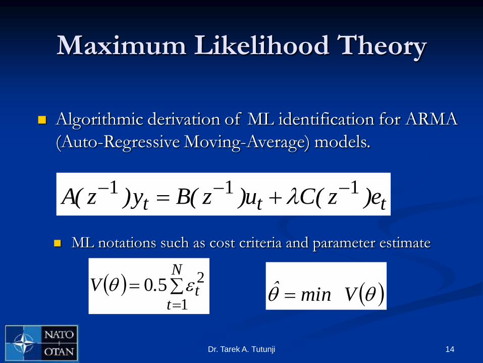
Maximum Likelihood Theory
ML notations such as cost criteria and parameter estimate
ttt e)z(Cu)z(By)z(A 111
Algorithmic derivation of ML identification for ARMA
(Auto-Regressive Moving-Average) models.
N
tt.V
1
250 Vminˆ
15Dr. Tarek A. Tutunji
Maximum Likelihood
to Prediction Error
Maximization of the likelihood function is
equivalent to minimizing the sum of the squared
prediction errors.
under the assumption of white Gaussian noise in the
ARMAX model
16Dr. Tarek A. Tutunji
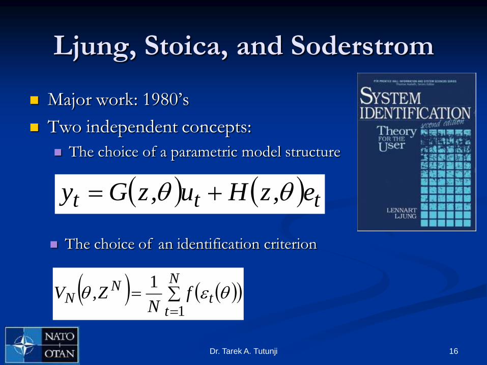
Ljung, Stoica, and Soderstrom
Major work: 1980‟s
Two independent concepts:
The choice of a parametric model structure
ttt e,zHu,zGy
N
tt
NN f
NZ,V
1
1
The choice of an identification criterion
17Dr. Tarek A. Tutunji
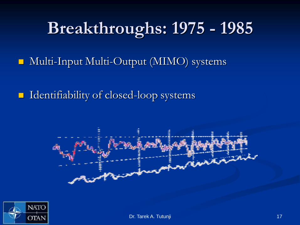
Breakthroughs: 1975 - 1985
Multi-Input Multi-Output (MIMO) systems
Identifiability of closed-loop systems
18Dr. Tarek A. Tutunji
Identification as a Design Problem
Identification can be viewed as an approximation
Estimated models are used for a specific purpose
The model error should be controlled in order not
to penalize the goal for which the model was built
for.
Goal-oriented design problem

19Dr. Tarek A. Tutunji
Identification for Control
In 1990, identification and control design were
looked as a combined design problem.

20Dr. Tarek A. Tutunji
System Identification Steps
1. Experiment design. This includes the choice of lab equipment to be used such as computers, DAQ, and interface.
2. Model structure determination. The choice of the model can range from nonparametric models, such as transient and frequency analysis, to parametric methods, such as difference equations and neural networks.
3. Experiment run. This is usually done by exciting the system with an input signal (pulse, sinusoid, or random) and measuring the output signal over a specified time interval.

21Dr. Tarek A. Tutunji
System Identification Steps
4. Algorithm choice and run. The algorithm used for
convergence can vary from simple one-shot least
squares, recursive least squares to advanced multi-
structures such as back propagation.
5. Validation of results. The output of the identified
model is compared to the original system through
different and „new‟ input signals.

22Dr. Tarek A. Tutunji
System Identification
Input
Model Output
Error
Actual Output
Real
System
System
Model
+
-

23Dr. Tarek A. Tutunji
System Identification:
ARMA Models
The standard Auto-Regressive Moving-Average model (ARMA)
is given below
m
iiki
n
jjkjk ubyay
01
where uk is the system input, yk is the system output ^yk is the predicted
output, a and b are the ARMA parameters. The goal is to minimize the error
between the desired and predicted outputs
K
kkk
K
kk yyeE
1
2
1
ˆmin
24Dr. Tarek A. Tutunji
System Identification:
ARMA Models
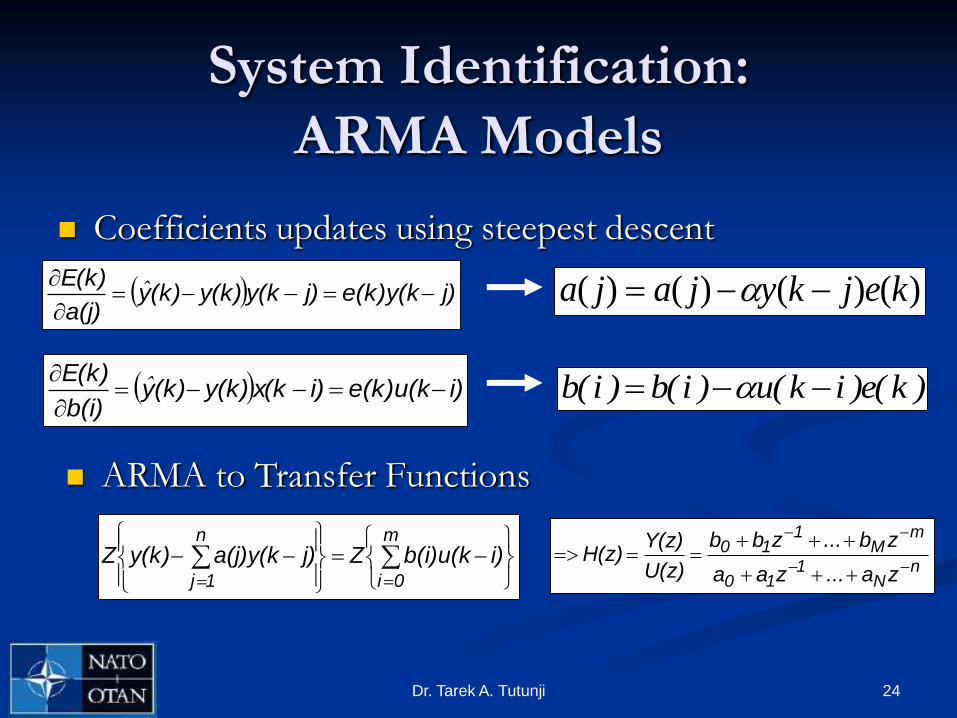
Coefficients updates using steepest descent
j)e(k)y(kj)y(ky(k)(k)ya(j)
E(k)
ˆ
i)e(k)u(ki)x(ky(k)(k)yb(i)
E(k)
ˆ
ARMA to Transfer Functions
m
0i
n
1j
i)b(i)u(kZj)a(j)y(ky(k)Zn
N1
10
mM
110
za...zaa
zb...zbb
U(z)
Y(z)H(z)
)()()()( kejkyjaja
)k(e)ik(u)i(b)i(b

Control Techniques
Tarek A. Tutunji

26Dr. Tarek A. Tutunji
Control Techniques / Strategies
Classical Control
Adaptive Control
Robust Control
Optimal Control
Variable Structure Control
Intelligent Control

27Dr. Tarek A. Tutunji
Classical Control
Classical control design are used for SISO
systems.
Most popular concepts are:
Bode plots
Nyquist Stability
Root locus.
PID is widely used in feedback systems.

28Dr. Tarek A. Tutunji
Classical Control: PID
Proportional-Integral-Derivative (PID) is the most
commonly used controller for SISO systems
dt
)t(deKdt)t(eK)t(eK)t(u DIp

29Dr. Tarek A. Tutunji
Classical vs. Modern Control
In contrast to the frequency domain analysis of the classical control theory, modern control theory utilizes the time-domain state space representation.
A mathematical model of a physical system as a set of input, output and state variables related by first-order differential equations.
The variables are expressed as vectors and the differential and algebraic equations are written in matrix form.
The state space representation provides a convenient and compact way to model and analyze systems with multiple inputs and outputs.

30Dr. Tarek A. Tutunji
Adaptive Control
Adaptive control involves modifying the control law used by a controller to cope with the fact that the parameters of the system being controlled are slowly time-varying or uncertain.
Such controllers use on-line identification of the process parameters.
For example, as an aircraft flies, its mass will slowly decrease as a result of fuel consumption; we need a control law that adapts itself to such changing conditions.

31Dr. Tarek A. Tutunji
Robust Control
Robust control is a branch of control theory that explicitly deals with uncertainty in its approach to controller design.
Robust control methods are designed to function properly so long as uncertain parameters or disturbances are within some set.
The state-space methods were sometimes found to lack robustness, prompting research to improve them. This was the start of the theory of Robust Control, which took shape in the 1980's and 1990's and is still active today.

32Dr. Tarek A. Tutunji
Adaptive vs. Robust Control
Adaptive control does not need a priori
information about the bounds on uncertainties
or time-varying parameters.
Robust control guarantees that if the changes are
within given bounds the control law need not be
changed, while adaptive control is precisely
concerned with control law changes.

33Dr. Tarek A. Tutunji
Optimal Control
Optimal control is a set of differential equations describing the paths of the state and control variables that minimize a “cost function”
For example, the jet thrusts of a satellite needed to bring it to desired trajectory that consume the least amount of fuel.
Two optimal control design methods have been widely used in industrial applications, as it has been shown they can guarantee closed-loop stability.
Model Predictive Control (MPC)
Linear-Quadratic-Gaussian control (LQG).
34Dr. Tarek A. Tutunji
Variable Structure Control
Variable structure control, or VSC, is a form of discontinuous nonlinear control.
The method alters the dynamics of a nonlinear system by application of a high-frequency switching control.
The main mode of VSC operation is sliding mode control (SMC).

35Dr. Tarek A. Tutunji
Intelligent Control
Intelligent Control is usually used when the mathematical model
for the plant is unavailable or highly complex.
The most two commonly used intelligent controllers are
Artificial Neural Networks
Fuzzy Logic

36Dr. Tarek A. Tutunji
Intelligent Control: Fuzzy
Fuzzy set theory provides mathematical tools for carrying out approximate reasoning processes when available information is uncertain, incomplete, imprecise, or vague.
Fuzzy logic controllers manage complex control problems through heuristics (IF … THEN) and mathematical models provided by fuzzy logic, rather than via mathematical models provided by differential equations.
This is particularly useful for controlling systems whose mathematical models are nonlinear or for which standard mathematical models are simply not available

37Dr. Tarek A. Tutunji
Fuzzy Control
38Dr. Tarek A. Tutunji
Intelligent Control: ANN
Artificial Neural networks (ANN) are nonlinear mathematical models that are used to mimic the biological neurons in the brain.
ANN are used as black box models to map unknown functions
ANN can be used for: Identification and Control

39Dr. Tarek A. Tutunji
ANN: Single Neuron
y
w0
w1
wM
x1
x2
xM
f(net)
M
mmmwxfy
1
40Dr. Tarek A. Tutunji
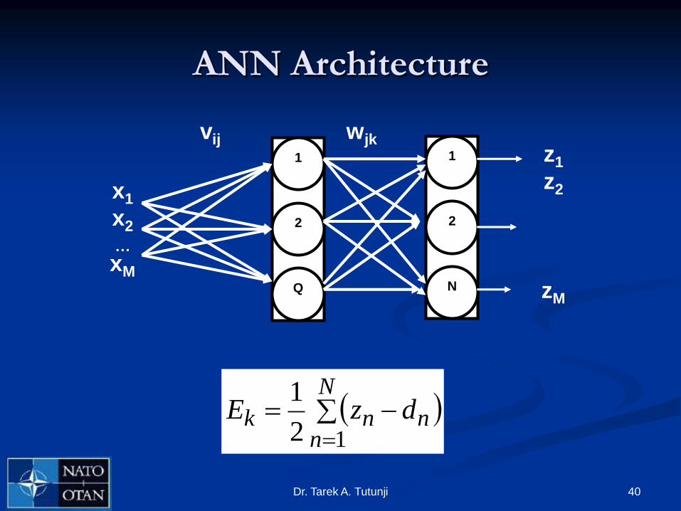
ANN Architecture
x1
x2
…
xM
1
2
Q
1
2
N
z1
z2
zM
vij wjk
N
nnnk dzE
12
1

41Dr. Tarek A. Tutunji
ANN: System Identification
In the identification process, the neural network is used to
approximate the nonlinear function. The structure of the
neural network plant model is given below, where the
blocks labelled TDL are tapped delay lines that store previous values of the input and output signals.
TDL
TDL
Weights
Weights
Activation
Function+ Weights +
Activation
Function
Plant
Output
Plant
Input
Net
Output
First Layer Second Layer

42Dr. Tarek A. Tutunji
ANN: Identification and Control
IdentificationControl
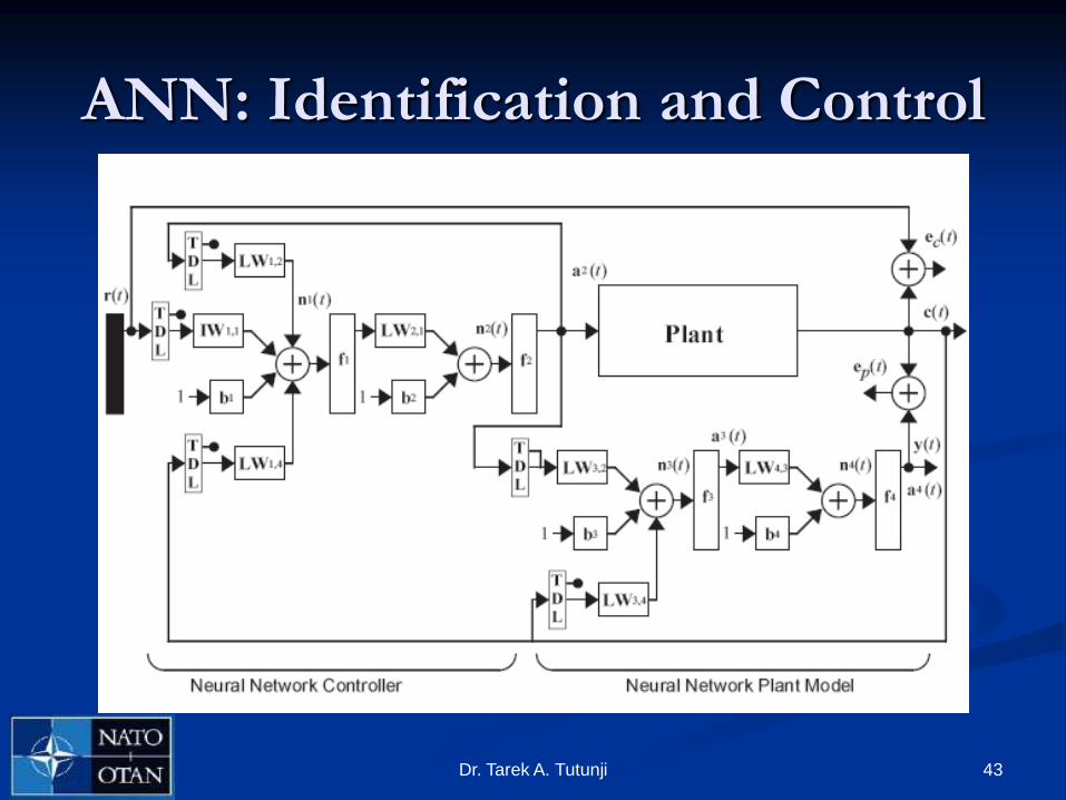
43Dr. Tarek A. Tutunji
ANN: Identification and Control
Hardware-in-the-Loop
Tarek A. Tutunji
Ashraf Saleem
45Dr. Tarek A. Tutunji
Hardware-in-the-Loop (HIL)
Classical Mechatronic systems are composed of controllers, actuators, and sensors.
Some components can be substituted by its model and simulated in real time.
The simulated components can be run in conjunction with real components under the same environment.
This environment is regarded as HIL

46Dr. Tarek A. Tutunji
HIL

Three-Stage Design
Procedure
Tarek A. Tutunji
Ashraf Saleem
48Dr. Tarek A. Tutunji
Three-Stage Design Procedure
Stage 1 online identification
The system-under-test is identified online using ARMA models
Stage 2 controller design
Models are used in simulation runs to design the controller
Stage 3 online control
The designed controllers are tuned and applied to the system-
under-test in Hardware-In-The-Loop (HIL) environment

49Dr. Tarek A. Tutunji
Three-Stage Design Procedure
Start
Connect
PC/DAQ to
the system
Approximate
Transfer
Function
using
ARMA / RLS
Design
Controller using
software
simulation
Tune and
Optimize
Controller
Apply
Impulse and
Measure
Response
Disconnect
system
Re-connect
PC/DAQ to
the system
Apply
Computer as
Controller
Fine-Tune the
Controller
End

50Dr. Tarek A. Tutunji
Stage 1: Online Identification
Impulse
PC / DAQ
System
Identification
Simulink
ARMA ModelRLS Algorithm
Electro-mechanical
system under test
Drive
Circuit Sensor
A/D
System Response

51Dr. Tarek A. Tutunji
Stage 2: Controller Design
Computer Simulation (using Simulink/Matlab)
Control SignalError Controller
Design
Identified
Transfer
Function
Reference
Model Response

52Dr. Tarek A. Tutunji
Stage 3: Online Control
PC / DAQ
Designed
Controller
Simulink
Electro-mechanical
system under test
Drive
Circuit Sensor
A/DSystem Response
Control
Signal

Case Studies
Tarek A. Tutunji
Ashraf Saleem
54Dr. Tarek A. Tutunji
Experimental Setup
Computer P4, 3GHz desktop MATLAB / Simulink
National Instruments DAQ card 6036E Sampling rate of 200 kS/s
Input voltage range of ± 10 V
Input signal to the system-under-test (PC output) was a voltage pulse.
The system response is the output (PC input)

55Dr. Tarek A. Tutunji
Experimental Setup
56Dr. Tarek A. Tutunji
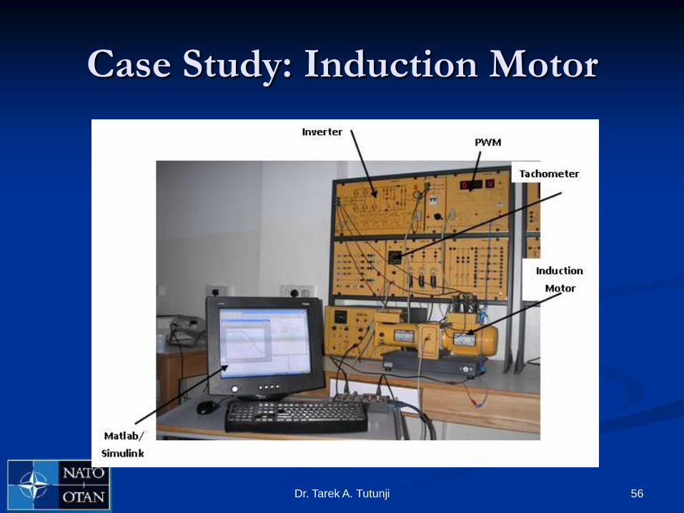
Case Study: Induction Motor

57Dr. Tarek A. Tutunji
Induction Motors
Due to their simple structure, reliability of operation and modest cost, the squirrel cage induction motors are the most widely used electrical drive motors.
Induction motors exhibit nonlinear dynamic behavior and therefore it is a challenge to establish an adequate mathematical model for controller design purposes.
The parameters of the induction motor may change during the operation of the drive system, causing deviations between the corresponding signals of the model and the motor.

58Dr. Tarek A. Tutunji
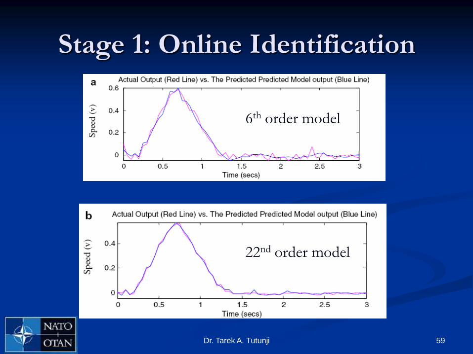
Stage 1: Online Identification
59Dr. Tarek A. Tutunji
Stage 1: Online Identification
22nd order model
6th order model

60Dr. Tarek A. Tutunji
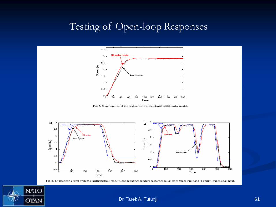
Stage 1: Online Identification
61Dr. Tarek A. Tutunji
Testing of Open-loop Responses

62Dr. Tarek A. Tutunji
Stage 2: Controller Design

63Dr. Tarek A. Tutunji
Stage 2: Control Design

64Dr. Tarek A. Tutunji
Stage 3: Online Control
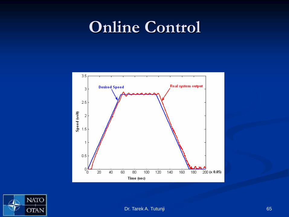
Online Control
65Dr. Tarek A. Tutunji
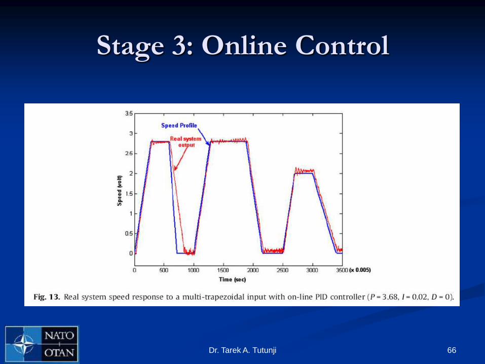
66Dr. Tarek A. Tutunji
Stage 3: Online Control

67Dr. Tarek A. Tutunji
Advantages of the Proposed Procedure
Accuracy in the identification model.
Flexibility in the controller design.
Optimizing time resources and minimizing the cost
The induction motor to be controlled will not be used during
the experimentation of the controller design and parameter
tuning and therefore the down time of the induction motor
will be minimized.
This might be a crucial time saving issue when the motor is
used production line. Equally important, damage to the
motor due to inappropriate parameter values is avoided.

68Dr. Tarek A. Tutunji
Case Study: Pneumatic System

69Dr. Tarek A. Tutunji
Pneumatic Systems
Pneumatic servo-drives play an important role in industrial mechatronic systems.
This is due to their cost effectiveness, easy maintenance, and clean operating conditions.
However, pneumatic actuators are characterized by high order time variant dynamics, nonlinearities due to compressibility of air, internal and external disturbances and payload variation

70Dr. Tarek A. Tutunji
Experiment Setup

71Dr. Tarek A. Tutunji
System Identification
72Dr. Tarek A. Tutunji
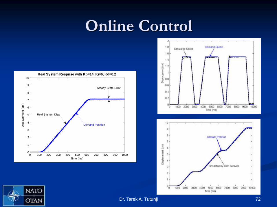
Online Control
0 100 200 300 400 500 600 700 800 900 10000
1
2
3
4
5
6
7
8
9
10
Time (ms)
Dis
pla
cem
ent
(cm
)
Real System Respnse with Kp=14, Ki=6, Kd=0.2
Real System Disp
Demand Position
Steady State Error
73Dr. Tarek A. Tutunji
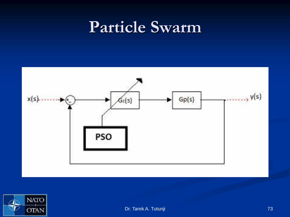
Particle Swarm

74Dr. Tarek A. Tutunji
Cascade Control
0 500 1000 1500 2000 2500 30000
1
2
3
4
5
6
7
8
Time(ms)
Positio
n
Real PositionSimulated Position
75Dr. Tarek A. Tutunji
Conclusions Identification and control play an essential role in the design of
mechatronic systems
System identification methods that use linear models, such as Auto-Regressive Moving-Average (ARMA), as well as nonlinear models, such as Artificial Neural Networks (ANN), were presented and compared.
Control methods that range from PID to intelligent controllers, such as fuzzy controllers, were presented and compared.

76Dr. Tarek A. Tutunji
Conclusions
A three-stage procedure for the identification and control of mechatronic systems was presented.1. The system-under-test is identified online using ARMA models.
2. These models are used in simulation runs to design the controller.
3. The designed controllers are applied to the system using HIL.
Experimental results for two case studies were presented in order to demonstrate the advantages of the procedure.
Finally, an UAV project that used a similar procedure was presented to illustrate the procedure‟s practicality.