identification and quantitative measurements of … and quantitative measurements of chemical...
TRANSCRIPT

Mark A. Zondlo and David S. BomseSouthwest Sciences, Inc., Santa Fe, New Mexico
Identification and Quantitative Measurementsof Chemical Species by Mass Spectrometry
NASA/CR—2005-213820
November 2005
https://ntrs.nasa.gov/search.jsp?R=20050245095 2018-07-13T12:50:16+00:00Z

The NASA STI Program Office . . . in Profile
Since its founding, NASA has been dedicated tothe advancement of aeronautics and spacescience. The NASA Scientific and TechnicalInformation (STI) Program Office plays a key partin helping NASA maintain this important role.
The NASA STI Program Office is operated byLangley Research Center, the Lead Center forNASA’s scientific and technical information. TheNASA STI Program Office provides access to theNASA STI Database, the largest collection ofaeronautical and space science STI in the world.The Program Office is also NASA’s institutionalmechanism for disseminating the results of itsresearch and development activities. These resultsare published by NASA in the NASA STI ReportSeries, which includes the following report types:
• TECHNICAL PUBLICATION. Reports ofcompleted research or a major significantphase of research that present the results ofNASA programs and include extensive dataor theoretical analysis. Includes compilationsof significant scientific and technical data andinformation deemed to be of continuingreference value. NASA’s counterpart of peer-reviewed formal professional papers buthas less stringent limitations on manuscriptlength and extent of graphic presentations.
• TECHNICAL MEMORANDUM. Scientificand technical findings that are preliminary orof specialized interest, e.g., quick releasereports, working papers, and bibliographiesthat contain minimal annotation. Does notcontain extensive analysis.
• CONTRACTOR REPORT. Scientific andtechnical findings by NASA-sponsoredcontractors and grantees.
• CONFERENCE PUBLICATION. Collectedpapers from scientific and technicalconferences, symposia, seminars, or othermeetings sponsored or cosponsored byNASA.
• SPECIAL PUBLICATION. Scientific,technical, or historical information fromNASA programs, projects, and missions,often concerned with subjects havingsubstantial public interest.
• TECHNICAL TRANSLATION. English-language translations of foreign scientificand technical material pertinent to NASA’smission.
Specialized services that complement the STIProgram Office’s diverse offerings includecreating custom thesauri, building customizeddatabases, organizing and publishing researchresults . . . even providing videos.
For more information about the NASA STIProgram Office, see the following:
• Access the NASA STI Program Home Pageat http://www.sti.nasa.gov
• E-mail your question via the Internet [email protected]
• Fax your question to the NASA AccessHelp Desk at 301–621–0134
• Telephone the NASA Access Help Desk at301–621–0390
• Write to: NASA Access Help Desk NASA Center for AeroSpace Information 7121 Standard Drive Hanover, MD 21076

Mark A. Zondlo and David S. BomseSouthwest Sciences, Inc., Santa Fe, New Mexico
Identification and Quantitative Measurementsof Chemical Species by Mass Spectrometry
NASA/CR—2005-213820
November 2005
National Aeronautics andSpace Administration
Glenn Research Center
Prepared under Contract NAS3–01164

Available from
NASA Center for Aerospace Information7121 Standard DriveHanover, MD 21076
National Technical Information Service5285 Port Royal RoadSpringfield, VA 22100
Trade names or manufacturers’ names are used in this report foridentification only. This usage does not constitute an officialendorsement, either expressed or implied, by the National
Aeronautics and Space Administration.
Available electronically at http://gltrs.grc.nasa.gov

1. Background
Mass spectrometry is often known as the gold standard of analytical chemistry techniques. Noother method can provide a similar combination of general utility, response time, and detectionsensitivity. But, mass spectrometers have typically been large, heavy, and required large amountsof power to operate.
In 1999, Southwest Sciences began working with Mass Sensors (St. Louis, MO) to develop aminiaturized version of a double-focusing type of mass spectrometer. Much of that work wassupported by NASA’s SBIR program. The analyzer portion of the Mass Sensors device – whichwas, in turn, based on intellectual property licensed from the University of Minnesota – is smallenough to fit in the palm of one hand. It uses a combined magnetic and electrostatic fields togenerate mass spectra; the magnetic field acts as a momentum selector (which is actually a massanalyzer) while the electrostatic field acts as an energy analyzer. Careful selection of the relativestrengths of the two types of fields improves mass resolution by reducing the effects of thedistribution of the ion kinetic energies. Although double-focusing mass spectrometers had beenknown for nearly 50 years, the key innovation in the Mass Sensors instrument was a novel methodfor constructing the elements used to generate the electrostatic field that nearly eliminated fielddistortion at the sides of the mass analyzer. This made it possible to shrink the analyzer so that iontrajectories filled nearly the entire open portion of the analyzer. Previous designs required theanalyzer to be substantially large than the ion path cross section in order to guarantee uniform fieldsalong the ion trajectories.
The SBIR-funded work at Southwest Sciences showed the instrument to operate well at ionmasses from about 15 to 110 daltons. The mass spectral peaks had a Gaussian shape with a fixedm/)m width that allowed straightforward deconvolution of overlapping mass peaks. The massspectrometer was equipped with a newly designed ion multiplier (Detector Technologies, Inc.) thatallowed operation at sample pressures up to 10-4 torr, or an order of magnitude larger than is possiblewith conventional ion multipliers. This higher pressure operation further increased detectionsensitivity by increasing the number density of analyte gas in the ion source region.
IDENTIFICATION AND QUANTITATIVE MEASUREMENTSOF CHEMICAL SPECIES BY MASS SPECTROMETRY
FinalMark A. Zondlo and David S. Bomse
Southwest Sciences, Inc.Santa Fe, NM 87505
NASA/CR—2005-213820 1

†See G. E. Patterson et al., “Miniature Cylindrical Ion Trap Mass Spectrometer,” AnalyticalChemistry 2002, 74, 6145-6153 and L. S. Ritter et al., “Analytical Performance of a Miniature
The initial success of Southwest Sciences’ work with the Mass Sensors mass spectrometermotivated the current project. A number of NASA programs – particularly space-borne andmicrogravity drop tower experiments – would benefit from the availability of a compact, trulyportable, mass spectrometer. Potential applications ranged from monitoring crew physiology onboard the ISS by measuring gases in exhaled breath to detecting reaction intermediates duringmicrogravity combustion. Despite the successes of the SBIR-funded work, Mass Sensors wasunable to commercialize their mass spectrometer technology. Nearly all of the instruments sufferedfrom performance degradation – diminished ion signals, reduced mass resolution, or both – on a timescale ranging from several hours to several days. This problem was attributed to deposition ontothe inner surface of the mass analyzer of pyrolysis products formed at the hot wire filament in theionizer. Performance could be restored by cleaning the analyzer, but the problem would recur onthe same short time scale. In some ways, the biggest unresolved question was why the instrumentthat was used at Southwest Sciences in the Phase II SBIR project performed as well as it did for suchan extended time.
Given their inability to produce reliable commercial instruments, Mass Sensors was unable to
When it became clear that Mass Sensors would not be able to meet the requirements of thisproject, Southwest Sciences turned to other sources of miniature mass spectrometers. Severalvendors were offering devices intended, for the most part, as benchtop analytic instruments and usedquadrupole, time-of-flight, or ion trap technology. We selected the quadrupole mass spectrometermanufactured by Ferran Scientific (San Diego, CA). Ferran’s technology was truly innovative. Themass analyzer consists of a 4 × 4 array of quadrupole rods that form a set of 9 (a 3 × 3 array)matched quadrupole filters operated in unison. The filter sits between a single ionization source andFaraday cup detector that serve all nine quadrupole sections. The entire assembly – ion source,quadrupole array, and Faraday cup – fits within a 12 cm3 vacuum enclosure. An electronics head,attached to the vacuum enclosure, measures 4.7 × 6.0 × 5.6 cm and weighs 100 g. The electronics
gm, and requires 1.5 A at 24 V DC.
We selected the Ferran device over other newly developed quadrupole mass spectrometers (suchas the Stanford Research and Infinicon instruments) because the Ferran is smaller, can operate athigher pressures, and uses less power. Similar concerns – particular the operating pressure andelectronics – helped rule out the ion traps and time-of-flight mass spectrometers. As massspectrometers get smaller, vacuum requirements become more important because the size, weight,and power needs of the vacuum pumps exceed those of the mass spectrometers. For example, theminiaturized cylindrical ion trap mass spectrometer developed by Prof. Graham Cooks at PurdueUniversity is roughly 1 cm3, but the entire instrument including pumps, electronics, and computerweighs 16 kg.† Much of the weight is due to the vacuum requirements.
NASA/CR—2005-213820 2
bring products to market and, ultimately, terminated their business in February 2004.
Cyclindrical Ion Trap Mass Spectrometer, Analytical Chemistry 2002, 74, 6154-6162.
base unit (computer network interface or CNI in Ferran’s syntax) is 5.9 × 14.0 ×16.1 cm, weighs 750

2. Physical Description of the Delivered System
Figure 2 - Photograph of the upper platform of the systemshowing the mass spectrometer, vacuum system, and gaschromatograph. There is room also for a carrier gas lecturebottle.
Figure 1. Photograph of the experimental setup. The top platecontains the sampling system (column, needle, valves) andturbomolecular pump while the lower plate contains theelectronics, controllers, and diaphragm pump. The entireassembly plugs into one 120 V AC outlet.
NASA/CR—2005-213820 3
The instrument operates using 120 VAC. Two uninterruptible power supplies (UPS) are included so that the user has a choice between operating time and UPS size and weight.
The completed mass spectrometer system is a fully-contained, automated instrument consisting of a needle sampling inlet, a custom-designed, small- scale gas chromatograph and a miniature, quadrupole mass spectrometer. The system is mounted on a two-tier, anodized aluminum breadboard having overall dimensions 38×45.5×30.5 cm, Figs. 1 and 2. The upper tier supports the sample control valves, chromatograph, mass spectrometer and controller, and turbomolecular pump. There is also space for a lecture bottle of helium to be used as the chromatograph carrier gas. The bottom tier contains a roughing pump and control electronics for the sampling inlet, chromatograph heater, multiport valve, and turbomolecular pump. A laptop computer that controls the instrument and collects data is also included.

3. Operation of the Delivered System
3.1 Mass Spectrometer
The Ferran Scientific Symphony quadrupole mass spectrometer, billed by the vendor as “theworld’s smallest mass spectrometer,” consists of three components. The micropole array (MPA)is the actual mass spectrometer that sits inside the vacuum system. It is a miniature array ofquadrupole mass spectrometers designed to operate simultaneously (in parallel). Atoms andmolecules are ionized in a single Nier-type ion source following electron impact (EI). Electrons areemitted from hot filaments located outside the field of view (main axis) of the quadrupole detector.Using electrostatic lenses, ions are extracted, focused, and injected into individual quadrupole massfilters. Ions with a specific mass-to-charge ratio are filtered by applying a combination of DC andRF voltages of the poles forming a quadrupole of the array. Filtered ions in each quadrupole arecollected on individual Faraday type detectors. All individual detectors contribute to generate asingle current signal. A mass spectrum is generated by scanning both AC and DC voltages appliedon the poles of the Micropole. The MPA chassis includes a total of 16 rods and 11 electrical pinsall secured in a glass-to-metal structure and sealed in a high temperature oven. Operation at hightemperature avoids the type of contamination that plagued the Mass Sensors design.
The electrostatic lenses, apertures, and plates are made of photo-etched parts. The sensorconstruction does not use ceramic parts to avoid the type of patch charging effects that are commonwith other quadrupole mass spectrometers.
The Ferran quadrupole can operate at one of two ionization settings: 70 eV and 43 eV. All ofthe development work was done using 70 eV ionization.
The second part of the Ferran massspectrometer is the spectra converter (SC),the blue box that attaches to the MPA and isshown in Fig. 3. The SC includes a pre-tunedRF power supply and an electrometer. Usinga built-in guide pin, the SC is easilyconnected and secured to the back of theMPA with a connector latch. Thecombination can be mounted in anyorientation. Ferran offers three differentsizes of MPA and three different spectraconverters. Specifications for the allowedcombinations of the micropoles and spectraconverters are listed in Table 1. Thecombination used in the deliverable ishighlighted; it was selected to give the bestcombination of mass range and resolution.
Figure 3 - Detail photograph of the spectraconverter (SC) on the Ferran Scientificquadrupole mass spectrometer.
NASA/CR—2005-213820 4

The third portion of the mass spectrometer, theComputer Network Interface (CNI), Fig. 4, includes thepower supplies, the control circuitry and thecommunications board. All circuits are driven by aninternal microcomputer and embedded control software(firmware). The CNI connects to a PC via RS-232, RS-485, or TCP/IP serial interface, and to the SC using ashielded cable. The CNI (and the rest of the massspectrometer) is powered by 24 V DC at up to 1.5 A.
An RS-232 serial interface is used in the deliverablefor communication between the host laptop computer andthe CNI. The settings are 9800 baud, 8 data bits, noparity, 1 stop bit, and XON/OFF flow control. Datastrings are terminated by a line feed character (decimal13). Communications with the CNI entail readingand/or writing a set of registers.
Figure 4 - Computer NetworkInterface (CNI) for the FerranScientific quadrupole massspectrometer.
MPA MPA6-1-2/45
MPA6-11-2/45
MPA6-5-2/6
MPA6-7-2/65
MPA6-5-2/100
MPA6-1-4/300
SC SC6-18 SC6-18 SC6-14 SC6-14 SC6-11 SC6-07
massrange
2-45 2 - 45 2 - 65 2 -65 2 - 100 4 - 300
resolution(FWHM) 0.5 1.5 0.8 0.9 1.0 1.5
pmax(torr) 1 × 10⁻³ 1 × 10⁻² 5 × 10⁻³ 7 × 10⁻³ 5 × 10⁻³ 1 × 10⁻³
Table 1 - Ferran Scientific Quadrupole Mass Spectrometers
NASA/CR—2005-213820 5

3.2 Gas Chromatograph
T h e c u s t o m g a sc h r o m a t o g r a p h u s e s amicropacked, HayeSepQ,Silcosteel ® column from Restek(2 m long × 1 mm i.d. × 1.59 mmo.d.). Silcosteel columns arecomposed of stainless steel on theoutside but contain an innercoating of silica. The silicacoating results in feweradsorption problems relative to astainless steel surface. Thestainless steel exterior providesmore rigidity and preventscolumn breakage, t ra i t sparticularly desirable for dropt o w e r a n d s p a c e - b o r n eenvironments. The Silcosteelcolumn contains 100/120 meshadsorbents of HayeSepQ, anadsorbent that shows excellentseparation for many organicspecies. The fine mesh allows fora large number of theoreticalplates, thereby allowing greaterseparation of species eluting fromthe column. We have also usedzero dead volume fittings where possible. Figure 5 shows chromatographs of mixtures of alkanes(top) and alkenes (bottom) in helium carrier gas.
The column is wrapped with thin (0.20mm diameter), polyimide-insulated nichromewire. By passing a current through thenichrome wire, the column can be resistivelyheated in a fast manner. The total resistanceof the wire used to wrap the column is 452Ohms, and thus currents of 0.25 A are used.The column is supported 3 cm above the topplate by three wires attached to posts. A fanwas placed 12 cm directly above the centerof the column for efficient and uniformcooling. Figure 6 shows a plot of thetemperature response for warming the
Figure 5 - Chromatograms of 1000 ppm calibration mixturesof alkanes (top) and alkenes (bottom) in helium.
Figure 6 - Response of the column temperature torapid warming and cooling.
NASA/CR—2005-213820 6

†See the Victrex web site: http://www.victrex.com/.
column from ambient temperatures to 155 °C starting at 70 s. The initial heating rate is ~ 90°C min-
The low thermal mass of the wire also allows for rapid cooling. At 410 s the heating stops, thefan is started, and an exponential temperature decay is observed with a time constant of ~ 40 s.Cooling the column to near ambient temperatures occurs within three minutes. Overall, the dutycycle due to heating and cooling of the column is ~ 10 minutes.
The column heater control and temperature monitoring are performed by a pair of PIDcontrollers (Omega CNi3222-C24). Two controllers are used because readout of the currenttemperature is not possible during programmed temperature ramp. Hence, the second controllersimply provides a measurement of the instantaneous temperature.
Gas sampling and introduction to the chromatographic column are controlled by a pair ofcommercial, computer-driven valves, Fig. 7. Samples are drawn through a needle into a smallreservoir using a three-port PEEK valve. The valve normally connects the reservoir to the vacuumpump so that the reservoir remains evacuated until a sample is acquired. Then, the valve switchesto admit gas through the sampling needle into the reservoir. Flow rates for typical sample durationsare limited by the conductance of the needle. PEEK was chosen because of its excellent chemicaland thermal stability†. We found PEEK valves to leak under vacuum; but this is not a problem forthe sample inlet that is pumped continuously. In this case, the chemical properties of the valve aremore important than its vacuum characteristics.
A ten-port, two-position, stainless steel and Nitronic 60 valve from Valco (P/N ET2C10UWT)is composed of stainless steel, has ten ports for 1/16" tubing, and is used to direct the sample fromthe reservoir to the chromatographic column. The valve is controlled by a 24 V DC microelectricactuator that can be switched by a 5 V logic signal from the computer. The valve can withstand upto 300 psi gas pressure and temperatures up to 330°C. The bores inside the valve are the same size
Figure 7 - Computer controlled valves used for sampling acquisition and for injecting thesampled gas onto the chromatographic column.
NASA/CR—2005-213820 7
1.

(0.75 mm) as the inner diameter of the tubing leading to the ports, thereby minimizing the amountof dead volume in the sampling regime. Although not all ten ports are needed for the currentinstrument design, the availability of additional ports for only a slight increase in cost allows forgreater adaptability in future applications as well as for redundancy if any of the ports becomeunuseable in the future.
3.3 Vacuum System
The delivered mass spectrometer system is equipped with a Pfeiffer Vacuum model TPD 011turbomolecular pump backed by a Pfeiffer MVP 015-2 diaphragm pump. The turbomolecular pumpand controller are visible in the photograph in Fig. 2. The pump is one of a new generation of small,lightweight turbo pumps, and has a nominal pumping speed of 10 liters sec-1 for N2 and 6 liters sec-1
for He with an ultimate pressure of better than 5 × 10⁻⁵ mbar (4 × 10⁻⁵ torr). It can tolerate a backingpressure of up to 25 mbar (19 torr). Compression ratios are 3 × 10⁶ and 3 × 10³ for N2 and He,respectively. The pump requires 1 A at 12 V DC and needs no external cooling. It weighs 1.8 kg.
One end of the diaphragm pump is visible in the photograph in Fig. 2. Rough outer dimensionsfor the MVP 015-2 diaphragm pump are 29 × 17 × 17 cm. The pump weighs 6.5 kg, draws 1.1 Aat 120 V AC (60 Hz), has a nominal pumping speed of 1.1 m3 hour-1 at 60 Hz, and can achieve anultimate pressure of 4 mbar (3 torr), or a factor of 6 better than required for the TPD 011turbomolecular pump.
3.4 Software
The delivered instrument is operated by a program, LabMPA-final written in LabVIEW thatcontrols a sampling valve to acquire the analyte, transfers the sample onto the gas chromatographcolumn, ramps the column temperature, measures the mass spectral ion intensities at a series of user-defined peaks, and records the data to disk in ASCII format.
Communication between LabMPA-final running on the laptop computer and the mass spectrometersystem uses a PCMCIA plug-in card that contains a pair of RS-232 serial ports. This brings to threethe total number of serial ports. The computer’s built-in port (COM1) provides communication withthe Ferran Scientific mass spectrometer’s computer network interface (CNI). The two ports on thePCMCIA card (COM4 and COM5) address a pair of PID temperature controllers (Omega modelCNi322-C24). One regulates the GC column temperature and the other reports the instantaneoustemperature back to the laptop. The program also accesses a National Instruments DAQCard-DIO-24 PCMCIA plug-in card that uses 0 to 5 V logic signals to control the two valves and the columncooling fan.
Figure 8 shows the user interface that appears when the program is first opened. The major usercontrols appear on the left-hand side of the panel. At the top, masses to scan, is the list of ion massesthat are acquired during each measurement. The next five items control the timing of the samplingand gc operation. The last of the group, set point, is the target maximum temperature achieved bythe chromatograph. We identify this value as a “target” temperature, because the upper bound is
NASA/CR—2005-213820 8

constrained by thermal loss to the surroundings and so is affected by ambient air temperature,humidity, and air currents.
The central region of the panel, dominated bythe chromatogram plot area, provides themeasurement results as acquired including theactual column temperature, the most recentlyacquired ion signals (in torr partial pressure), andthe elapsed time in seconds.
The right-hand region is used primarily fordebugging and to help the user examine raw signalsbetween the host computer and the Ferrancontroller.
Figure 8 - Front panel of the LabVIEW program used to control the mass spectrometer systemand collect and store the chromatographic data.
Figure 9 - Detail of program front panelshowing the key timing and temperaturecontrols.
NASA/CR—2005-213820 9
Figure 9, shows the six major controls from the program main panel, and describes their use. This information is displayed graphically on a time line in Fig. 10. The setpoint temperature is a target value that, for

the ambient air temperature, humidity, andair currents. We have found it useful to seta target above the maximum achievabletemperature since this drives the PIDtemperature controller more strongly at theupper end of the temperature cycle andhelps maintain a linear temperature ramp.
Experimental results are written to diskin ASCII format comma-delineated rowsand columns. In all cases, the first columnis the measurement time (relative to 0.0 atthe start of the run), followed by thecolumn temperature in °C. Then comes thepartial pressures in torr for the selected ion signals. The temporal resolution is determined by thenumber of mass peaks measured because the Ferran computer network interface establishes aminimum dwell time of 0.6 seconds per mass peak. The text box below is a portion of a data setacquired when the instrument was being set up and demonstrated at NASA Glenn Research Center
methane, ethane, propane, n-butane, n-pentane, and n-hexane).
The full data set is shown graphically in Fig. 11. The large mass 28 background and the noiseare due to some air contaminating the helium carrier gas.
The LabVIEW program LabMPA-final automatically saves each chromatogram to disk using anautomatically generated filename AUTOSAVE_nnnnn.TXT where nnnnn is a number beginning with00000 that is incremented to prevent duplicating files. The user is given the opportunity to renamethe autosaved file at the end of each run.
Figure 10 - Timing diagram for the LabVIEWprogram.
time, temp, amu0028, amu0043, amu00571.0586E+1, 2.6600E+1, 8.3660E-6, 7.6010E-7, 6.3700E-71.3979E+1, 2.6600E+1, 6.8930E-6, 7.5580E-7, 6.1260E-71.8120E+1, 2.6500E+1, 6.4640E-6, 7.4810E-7, 6.3390E-72.2302E+1, 2.6500E+1, 6.1880E-6, 7.4990E-7, 6.2860E-72.6548E+1, 2.6500E+1, 6.2140E-6, 7.4610E-7, 6.2650E-73.0242E+1, 2.6500E+1, 5.9070E-6, 7.4630E-7, 6.2370E-73.4475E+1, 2.6600E+1, 6.0410E-6, 7.2740E-7, 6.3020E-73.8620E+1, 2.6600E+1, 5.8840E-6, 7.4380E-7, 6.3960E-7
NASA/CR—2005-213820 10
temperatures $190 °C, may be limited by
in August 2004. The demonstration used a calibration mixture of alkanes (1000 ppm each of

Figure 11 - Chromatographic and temperature data fromdemonstration run.
NASA/CR—2005-213820 11

Appendix ALabVIEW source code
NASA/CR—2005-213820 12

LabMPA-final.viC:\WPDocs\Contracts\C01-07 (NASA ITD mass spec)\ITDlaptop\Ferran_MPA.llb\ITD\LabMPA-final.viLast modified on 8/31/2004 at 2:08 PMPrinted on 12/20/2004 at 4:14 PM
Page 1
0
loop counter
0.0time
status
0
code
source
error out
STOP
stop
43
43
43
43
28
43
43
0
masses to scan
Read masses
1.0E-7
0.0E+0
1.0E-8
2.0E-8
3.0E-8
4.0E-8
5.0E-8
6.0E-8
7.0E-8
8.0E-8
9.0E-8
1002.010.5 100.0 200.0 300.0 400.0 500.0 600.0 700.0 800.0 900.0
mass 28
mass 43
mass 57
chromatgram
600
Ramp time (s)
2.00
Sample duration (s)
60
Sample time (s)
0.0
column T (deg C)
220.0
Setpoint
0
wait loop
status of scan
0
scan count
write statement output
end status
problem
0
Soak time (s)
100
ramp start
0
sequence
error found?
0
results
most recent data file:
NASA/CR—2005-213820 13

HierarchyLast modified on 12/20/2004 at 4:15 PMPrinted on 12/20/2004 at 4:16 PM
Page 1
NASA/CR—2005-213820 14

Lab M
P A-f
inal
.vi
C:\W
P Doc
s\Co
n tra
cts\
C01-
07 (
NAS
A IT
D m
ass
spec
)\IT
Dla
p top
\Fer
ran _
MP A
.llb \
ITD
\Lab
MP A
-fin
al.v
iLa
st m
o difi
ed o
n 8 /
3 1/2
0 04
at 2
:08
P MP r
inte
d on
12/
20/2
004
at 4
:18
P M
P ag e
1
COM
1
mas
ses
to s
can
writ
e st
atem
ent
outp
ut
Sec
on
d p
art
of
init
iali
zati
on
ro
uti
ne.
Init
iate
ser
ial
com
mu
nic
atio
ns
wit
h F
erra
n,
form
at t
he
arra
y of
sel
ecte
d m
asse
s,
and
tel
l Fe
rran
to
get
sta
rted
.
XON
/XO
FF
LegP
lots
Plot
.Nam
eAc
tPlo
t
chr o
mat
gram
mas
s %
d
mas
ses
to s
can
(out
)
Wri
te m
ass
ID's
to
the
plot
lege
nd
1 [0
..2]
erro
r ou
t
NASA/CR—2005-213820 15

Lab M
P A-f
inal
.vi
C:\W
P Doc
s\Co
n tra
cts\
C01-
07 (
NAS
A IT
D m
ass
spec
)\IT
Dla
p top
\Fer
ran _
MP A
.llb \
ITD
\Lab
MP A
-fin
al.v
iLa
st m
o difi
ed o
n 8 /
3 1/2
0 04
at 2
:08
P MP r
inte
d on
12/
20/2
004
at 4
:18
P M
P ag e
2
writ
e st
atem
ent
outp
ut
end
stat
us
Rea
d m
asse
s
stat
us o
f sc
an
erro
r ou
t0
wai
t lo
op0
initi
aliz
ing
Firs
t p
art
of
init
iali
zati
on
rou
tin
e.
Cle
ar t
he
stri
ng
in
dic
ato
rs,
erro
r cl
ust
er,
and
wai
t lo
op
co
un
ter.
U
pd
ate
"sta
tus
of
scan
"
erro
r fo
und?
prob
lem
colu
mn
T (d
eg C
)
0 [0
..2]
NASA/CR—2005-213820 16

Lab M
P A-f
inal
.vi
C:\W
P Doc
s\Co
n tra
cts\
C01-
07 (
NAS
A IT
D m
ass
spec
)\IT
Dla
p top
\Fer
ran _
MP A
.llb \
ITD
\Lab
MP A
-fin
al.v
iLa
st m
o difi
ed o
n 8 /
3 1/2
0 04
at 2
:08
P MP r
inte
d on
12/
20/2
004
at 4
:18
P M
P ag e
3
time
colu
mn
T (d
eg C
)
Stri
ngs[
4]
stop
STO
P
STO
P
STO
P
STO
P
0
Get
mea
sure
men
t ti
me,
read
tem
per
atu
re,
and
up
da
te l
ab
el
on
ST
OP
bu
tto
n.
2 [0
..4]
0.00
0 0
Her
e's
the
imp
ort
an
t st
uff
.
1.
Co
nst
ruct
th
e st
rin
g a
rray
s n
eed
ed t
o p
rog
ram
th
e Fe
rran
an
d
the
gas
co
llec
tio
n/s
amp
lin
g s
yste
m.
2.
Lo
op
rep
eate
dly
to
co
llec
t d
ata
.
Ram
p ti
me
(s)
Sam
ple
dura
tion
(s)
Sam
ple
tim
e (s
)
0
Setp
oint
Soak
tim
e (s
)
ram
p st
art
0
end
stat
us
prob
lem
An
d d
on
e!
3.
Hal
t th
e m
ass
scan
a
nd
tu
rn o
ff t
he
ma
ss
spec
fil
amen
t.
4.
Sa
ve d
ata
to
dis
k
in c
omm
a-d
elim
ited
A
SC
II f
orm
at.
100
350
Rea
d st
art
time
mos
t r e
cent
dat
a fil
e:
2 [0
..2]
NASA/CR—2005-213820 17

Lab M
P A-f
inal
.vi
C:\W
P Doc
s\Co
n tra
cts\
C01-
07 (
NAS
A IT
D m
ass
spec
)\IT
Dla
p top
\Fer
ran _
MP A
.llb \
ITD
\Lab
MP A
-fin
al.v
iLa
st m
o difi
ed o
n 8 /
3 1/2
0 04
at 2
:08
P MP r
inte
d on
12/
20/2
004
at 4
:18
P M
P ag e
4
stat
us o
f sc
anst
artin
g ne
w s
eque
nce
Str i
ngs[
4]
stop
AB
OR
T
AB
OR
T
AB
OR
T
AB
OR
T
0
stop
True
0 [0
..4]
Fals
e
NASA/CR—2005-213820 18

Lab M
P A-f
inal
.vi
C:\W
P Doc
s\Co
n tra
cts\
C01-
07 (
NAS
A IT
D m
ass
spec
)\IT
Dla
p top
\Fer
ran _
MP A
.llb \
ITD
\Lab
MP A
-fin
al.v
iLa
st m
o difi
ed o
n 8 /
3 1/2
0 04
at 2
:08
P MP r
inte
d on
12/
20/2
004
at 4
:18
P M
P ag e
5
Wai
t fo
r Fe
rran
to
rep
ort
hav
ing
fin
ish
ed a
mas
s sc
an
wai
t lo
op
stat
us o
f sc
an
scan
cou
nt
stop
erro
r ou
t
1 [0
..4]
NASA/CR—2005-213820 19

Lab M
P A-f
inal
.vi
C:\W
P Doc
s\Co
n tra
cts\
C01-
07 (
NAS
A IT
D m
ass
spec
)\IT
Dla
p top
\Fer
ran _
MP A
.llb \
ITD
\Lab
MP A
-fin
al.v
iLa
st m
o difi
ed o
n 8 /
3 1/2
0 04
at 2
:08
P MP r
inte
d on
12/
20/2
004
at 4
:18
P M
P ag e
6
sequ
ence
Rea
d m
asse
s
err o
r fo
und?
chr o
mat
gram
Key
VI:
R
ead
an
d p
lot
mas
s si
gn
als,
set
val
ves,
set
tem
per
atu
re.
Prog
ram
resu
lts
3 [0
..4]
NASA/CR—2005-213820 20

Lab M
P A-f
inal
.vi
C:\W
P Doc
s\Co
n tra
cts\
C01-
07 (
NAS
A IT
D m
ass
spec
)\IT
Dla
p top
\Fer
ran _
MP A
.llb \
ITD
\Lab
MP A
-fin
al.v
iLa
st m
o difi
ed o
n 8 /
3 1/2
0 04
at 2
:08
P MP r
inte
d on
12/
20/2
004
at 4
:18
P M
P ag e
7
loop
cou
nter
stop
stat
us
erro
r ou
t
En
d o
f th
e o
ute
r lo
op
.
Up
dat
e lo
op
co
un
ter
ST
OP
if
use
r h
as
pre
ssed
th
e st
op
bu
tto
n o
r
on
err
or,
els
e co
nti
nu
e.
4 [0
..4]
NASA/CR—2005-213820 21

DSB
init
com
mu n
icat
ion s
an d
clo
se a
ll va
lves
.vi
C:\W
P Doc
s\Co
n tra
cts\
C01-
07 (
NAS
A IT
D m
ass
spec
)\IT
Dla
p top
\Fer
ran _
MP A
.llb \
DS B
init
com
mu n
icat
ion s
an d
clo
se a
ll va
lves
.vi
Last
mo d
ified
on
8 /3 1
/20 0
4 at
2:0
8 P M
P rin
ted
on 1
2/20
/200
4 at
4:2
0 P M
P ag e
1
RI0
002\
r
RI1
009\
r
12 12 23 0
0R
T100
2\r
161
Set
all v
alve
s of
f
1
erro
r in
(no
err
or)
erro
r ou
t
Fer r
an V
I SA
Res
our c
e N
ame
(out
)
Fer
r an
VISA
Res
our c
e N
ame
(in)
baud
rat
e (9
600)
data
bits
(8)
parit
y (0
:non
e)
stop
bits
(10
: 1
bit)
flow
con
trol
(0:
none
)
ter m
inat
ion
char
(0xA
= '\
n' =
LF)
NASA/CR—2005-213820 22

DSB
init
prio
ritie
s, s
tart
sto
p am
u s, M
PA p
aram
s.vi
C:\W
P Doc
s\Co
n tra
cts\
C01-
07 (
NAS
A IT
D m
ass
spec
)\IT
Dla
p top
\Fer
ran _
MP A
.llb \
DS B
init
p rio
ritie
s, s
tart
sto
p am
u s,
MP A
p a
ram
s.vi
Last
mo d
ified
on
8 /3 1
/20 0
4 at
2:0
8 P M
Prin
ted
on 1
2/20
/200
4 at
4:2
1 PM
P ag e
1
I niti
aliz
e pr
iorit
ies,
sta
rtin
g an
d st
oppi
ng a
mu'
s, M
PA p
aram
eter
s
WP
1Set
glob
al p
riorit
ies
at z
ero,
set
sel
ecte
d m
ass
prio
ritie
s at
1
The
abov
e su
b-VI
for
mul
ates
writ
e st
rings
fro
m t
he a
rray
of
mas
ses;
in
put
para
met
ers
are
the
arra
y , t
hede
sire
d co
mm
and
strin
g, t
he v
alue
to
be w
ritte
n.
In t
his
case
, it
will
mak
e a
strin
g:
"WP0
0xx,
0001
\r"
whe
re x
x is
the
mas
s (a
rray
ele
men
t) o
f in
tere
st.
WR
0001
,0.0
00E+
00\r
WI0
019,
0000
\r
WI0
006,
-001
\r
\r
WI0
017,
%04
d
\r
WI0
018,
%04
d
012 12 12 17 12 0
0
12
1 [0
..1]
mas
ses
to s
can
(in)
find
max
, min
of
arra
yva
lues
; se
t sc
an r
ange
regi
ster
s (I
0017
, I0
018)
VISA
res
our c
e na
me
(in)
VISA
res
our c
e na
me
(out
)
erro
r in
(no
err
or)
mas
ses
to s
can
(out
)
erro
r ou
t
0
0
NASA/CR—2005-213820 23

DSB
init
prio
ritie
s, s
tart
sto
p am
u s, M
PA p
aram
s.vi
C:\W
P Doc
s\Co
n tra
cts\
C01-
07 (
NAS
A IT
D m
ass
spec
)\IT
Dla
p top
\Fer
ran _
MP A
.llb \
DS B
init
p rio
ritie
s, s
tart
sto
p am
u s,
MP A
p a
ram
s.vi
Last
mo d
ified
on
8 /3 1
/20 0
4 at
2:0
8 P M
Prin
ted
on 1
2/20
/200
4 at
4:2
1 PM
P ag e
2
WR
0005
,5.2
26E+
03\r
WI 0
015,
030
WI0
014,
0001
\rW
I002
8,00
00\r
WR
0006
,8.0
00E+
00\r
WR
0007
,5.8
90E+
00\r
WR
0009
,1.0
02E+
00\r
I niti
aliz
e pa
ram
eter
s fo
r M
PA:
70
eV,
fast
mod
e
WR
0010
,5.5
00E+
04\r
WI0
023,
0000
\r
WI0
020,
0000
\r
WI 0
021,
0007
\r
WI0
004,
0001
\r
WI0
012,
0012
\r
WI0
013,
0020
\r
WR
0008
,1.0
00E+
00\r
17 17 17 17 17 12 12 17 12 12 12 12 12 12 12
0
0 [0
..1]
NASA/CR—2005-213820 24

DSB
set
up
scan
arr
ays
and
clu s
ter.
viC:
\WP D
ocs\
Con t
ract
s\C0
1 -0 7
(N
ASA
ITD
mas
s sp
ec)\
ITD
lap t
op\F
erra
n _M
P A.ll
b \D
S B s
et u
p sc
an a
rray
s an
d cl
u ste
r.vi
Last
mo d
ified
on
8 /3 1
/20 0
4 at
2:0
8 P M
P rin
ted
on 1
2/20
/200
4 at
4:2
3 P M
P ag e
1
RA
17mak
es
arr a
yof
0
0
The
sub
VI t
o th
e be
low
rig
ht
form
ulat
es a
nar
ray
of
com
man
d st
rings
fro
m
the
arra
y of
Ram
p tim
e (s
)
Sam
ple
dura
tion
(s)
Sam
ple
time
(s)
Setp
oint
Soak
tim
e (s
)
star
t tr
ap h
eate
r
ram
p st
art
send
to
MS
Setp
oint
Soak
tim
e (s
)R
amp
time
(s)
ram
p st
art
send
to
MS
star
t H
e pu
rge
Sam
ple
dura
tion
(s)
Sam
ple
time
(s)
0 0.00
0 0 0 0 0 0.00
sam
plin
g pa
ram
s
erro
r in
(no
err
or)
erro
r ou
t
mas
ses
to s
can
(in)
mas
ses
to s
can
(out
)
byte
cou
nt a
r ray
RA a
rray
NASA/CR—2005-213820 25

DSB
sta
rt s
can .
viC:
\WP D
ocs\
Con t
ract
s\C0
1 -0 7
(N
ASA
ITD
mas
s sp
ec)\
ITD
lap t
op\F
erra
n _M
P A.ll
b \D
S B s
tart
sca
n .vi
Last
mo d
ified
on
8 /3 1
/20 0
4 at
2:0
8 P M
P rin
ted
on 1
2/20
/200
4 at
4:2
4 P M
P ag e
1
Sta
r t s
can
1212 12 12 12 26
0
RI00
02\r
RI00
01\r
RI10
09\r
RT10
04\r
RI10
09\r
WI 0
001,
0001
\r0
writ
e st
atem
ent
outp
ut
VISA
res
our c
e na
me
VISA
res
our c
e na
me(
out)
erro
r in
(no
err
or)
erro
r ou
t
1 4
1
NASA/CR—2005-213820 26

DSB
get
cyc
le n
u mb e
r er
ror.
viC:
\WP D
ocs\
Con t
ract
s\C0
1-07
(N
ASA
ITD
mas
s sp
ec)\
ITD
lap t
op\F
erra
n _M
P A.ll
b \D
S B g
et c
ycle
nu m
b er
erro
r.vi
Last
mo d
ified
on
8 /3 1
/20 0
4 at
2:0
8 P M
P rin
ted
on 1
2/20
/200
4 at
4:2
5 P M
P ag e
1
err o
r in
(no
er r
or)
err o
r ou
tab
ort?
stat
us
5005
wai
t lo
op a
bor t
ed
True
Fals
e
NASA/CR—2005-213820 27

arra
yVIS
Awri
tere
ad.v
iC:
\WP D
ocs\
Con t
ract
s\C0
1 -0 7
(N
ASA
ITD
mas
s sp
ec)\
ITD
lap t
o p\F
erra
n _M
P A.ll
b \ar
rayV
ISAw
riter
ead .
viLa
st m
o difi
ed o
n 8 /
3 1/2
0 04
at 2
:08
P MP r
inte
d on
12/
20/2
004
at 4
:27
P M
P ag e
1 erro
r ou
t
erro
r in
appe
nded
arr
ay s
tate
men
ts
I niti
aliz
e VI
SA:
Inp
uts
an a
ppen
ded
arr a
y of
str
ing
expr
essi
ons
to w
r ite
and
out
puts
the
val
ues.
Th
e nu
mbe
r of
byte
s in
itial
ly a
t th
e se
r ial
por
t is
set
to
zer o
.
expe
cted
byt
e co
unt
0
VISA
res
our c
e na
me
outp
ut s
trin
g
outp
ut a
rray
NASA/CR—2005-213820 28

wai
t w
ith e
rror
clu
ster
s.vi
C:\W
P Doc
s\Co
n tra
cts\
C01-
07 (
NAS
A IT
D m
ass
spec
)\IT
Dla
p top
\Fer
ran _
MP A
.llb \
wai
t w
ith e
rror
clu
ster
s.vi
Last
mo d
ified
on
8 /3 1
/20 0
4 at
2:0
8 P M
P rin
ted
on 1
2/20
/200
4 at
4:2
8 P M
P ag e
1
err o
r in
(no
er r
or)
err o
r ou
t
mill
isec
onds
to
wai
t
NASA/CR—2005-213820 29

DSB
ela
p sed
tim
e.vi
C:\W
P Doc
s\Co
n tra
cts\
C01-
07 (
NAS
A IT
D m
ass
spec
)\IT
Dla
p top
\Fer
ran _
MP A
.llb \
DS B
ela
p sed
tim
e.vi
Last
mo d
ified
on
8 /3 1
/20 0
4 at
2:0
8 P M
P rin
ted
on 1
2/20
/200
4 at
4:2
9 P M
P ag e
1
1000
.00
star
t tim
e m
s (o
ut)
star
t tim
e m
s (i
n)el
apse
d tim
e (s
ecs)
NASA/CR—2005-213820 30

DSB
get
tim
e an
d te
mp e
ratu
re.v
iC:
\WP D
ocs\
Con t
ract
s\C0
1-07
(N
ASA
ITD
mas
s sp
ec)\
ITD
lapt
op\F
erra
n _M
P A.ll
b \D
S B g
et t
ime
and
tem
p era
ture
.vi
Last
mo d
ified
on
8 /3 1
/20 0
4 at
2:0
8 P M
P rin
ted
on 1
2/20
/200
4 at
4:3
0 P M
P ag e
1
time
tem
pera
ture
star
t tim
e m
s (i
n)
star
t tim
e m
s (o
ut)
COM
4
X01
11
*01X
01\r
1 [0
..1]
erro
r in
(no
err
or)
erro
r ou
t
Use
seq
uenc
e st
ruct
ure
to g
uara
ntee
tha
t tim
e is
mea
sure
d fir
stth
en t
empe
ratu
re.
NASA/CR—2005-213820 31

DSB
get
tim
e an
d te
mp e
ratu
re.v
iC:
\WP D
ocs\
Con t
ract
s\C0
1-07
(N
ASA
ITD
mas
s sp
ec)\
ITD
lapt
op\F
erra
n _M
P A.ll
b \D
S B g
et t
ime
and
tem
p era
ture
.vi
Last
mo d
ified
on
8 /3 1
/20 0
4 at
2:0
8 P M
P rin
ted
on 1
2/20
/200
4 at
4:3
0 P M
P ag e
2
Mak
e tim
e st
amp
0 [0
..1]
NASA/CR—2005-213820 32

VISAwritereadMAZ.viC:\WPDocs\Contracts\C01-07 (NASA ITD mass spec)\ITDlaptop\Ferran_MPA.llb\VISAwritereadMAZ.viLast modified on 8/31/2004 at 2:08 PMPrinted on 12/20/2004 at 4:31 PM
Page 1
expected byte count on read
VISA resource name
write buffer ("")
error in (no error)
return count on write
return count on read
read buffer
error out
5001
Incorrect number of bytes written
50
5
5002
expected byte counts not read
10
NASA/CR—2005-213820 33

DSB clear buffer.viC:\WPDocs\Contracts\C01-07 (NASA ITD mass spec)\ITDlaptop\Ferran_MPA.llb\DSB clear buffer.viLast modified on 8/31/2004 at 2:08 PMPrinted on 12/20/2004 at 4:32 PM
Page 1
Instr
Bytes at Portread buffer
50
False Loop Count
Max Tries
error in (no error)
error out
5000
Buffer not cleared
reference dup VISA resource name
Number of Bytes at Serial Port at start
True
NASA/CR—2005-213820 34

DSB
do
one
big
dat
a cy
cle.
viC:
\WP D
ocs\
Con t
ract
s\C0
1-07
(N
ASA
ITD
mas
s sp
ec)\
ITD
lapt
op\F
erra
n _M
P A.ll
b \D
S B d
o on
e b
ig d
ata
cycl
e.vi
Last
mo d
ified
on
8 /3 1
/20 0
4 at
2:0
8 P M
P rin
ted
on 1
2/20
/200
4 at
4:3
4 P M
P ag e
1
Stat
us
sequ
ence
(ou
t)
carr
ier
flow
val
ve
sam
ple
valv
e
to m
ass
spec
val
ve
Read
mas
ses
valu
es
erro
r fo
und?
(X a
nd Y
arr
ays)
erro
r in
(no
err
or)
erro
r ou
t
old
data
(in
)ne
w d
ata
(out
)
time
sequ
ence
(in
)
end?
tem
per a
tur e
sam
plin
g pa
ram
s
VISA
res
our c
e na
me
(in)
expe
cted
byt
e co
unt
appe
nded
arr
ay s
tate
men
ts
to G
C/M
S
NASA/CR—2005-213820 35

DSB
par
se d
ata
arra
y w
ith e
rro r
s.vi
C:\W
P Doc
s\Co
n tra
cts\
C01 -
0 7 (
NAS
A IT
D m
ass
spec
)\IT
Dla
p top
\Fer
ran _
MP A
.llb \
DS B
par
se d
ata
arra
y w
ith e
rro r
s.vi
Last
mo d
ified
on
8 /3 1
/20 0
4 at
2:0
8 P M
P rin
ted
on 1
2/20
/200
4 at
4:3
5 P M
P ag e
1
data
str
ing
arr a
y
erro
r in
(no
err
or)
err o
r ou
t
star
t ch
arac
ter
expe
cted
byt
e co
unt
valu
es
erro
r fo
und?
%e
5001
Size
mis
mat
ch
Fals
e
stat
usst
atus
True
NASA/CR—2005-213820 36

DSB
rea
d an
d co
n ver
t m
ass
inte
n siti
es.v
iC:
\WP D
ocs\
Con t
ract
s\C0
1-07
(N
ASA
ITD
mas
s sp
ec)\
ITD
lap t
op\F
erra
n _M
P A.ll
b \D
S B r
ead
and
con v
ert
mas
s in
ten s
ities
.vi
Last
mo d
ified
on
8 /3 1
/20 0
4 at
2:0
8 P M
P rin
ted
on 1
2/20
/200
4 at
4:3
6 P M
P ag e
1
Read
the
mas
s st
rings
Rea
d m
asse
sva
lues
appe
nded
ar r
ay s
tate
men
ts
expe
cted
byt
e co
unt
VISA
res
our c
e na
me
(in)
erro
r in
(no
err
or)
erro
r ou
t
VISA
res
our c
e na
me
(out
)
old
styl
e ?
7
extr
acts
the
val
ues
from
the
str
ings
stat
us
Tr u
e
erro
r fo
und?
NASA/CR—2005-213820 37

DSB
rea
d an
d co
n ver
t m
ass
inte
n siti
es.v
iC:
\WP D
ocs\
Con t
ract
s\C0
1-07
(N
ASA
ITD
mas
s sp
ec)\
ITD
lap t
op\F
erra
n _M
P A.ll
b \D
S B r
ead
and
con v
ert
mas
s in
ten s
ities
.vi
Last
mo d
ified
on
8 /3 1
/20 0
4 at
2:0
8 P M
P rin
ted
on 1
2/20
/200
4 at
4:3
6 P M
P ag e
2
Fal
se
NASA/CR—2005-213820 38

DSB
val
ve c
ontr
ols,
etc
.vi
C:\W
P Doc
s\Co
n tra
cts\
C01 -
0 7 (
NAS
A IT
D m
ass
spec
)\IT
Dla
p to p
\Fer
ran _
MP A
.llb \
DS B
val
ve c
o ntr
o ls,
etc
.vi
Last
mo d
ified
on
8 /3 1
/20 0
4 at
2:0
8 P M
P rin
ted
on 1
2/20
/200
4 at
4:3
7 P M
P ag e
1
need
le
FAN
POS
a
1
1
0 00 421
POS
b08
"Ind
ivid
ual"
Stat
us
sequ
ence
(in
)
sam
plin
g pa
ram
s
time
sequ
ence
(ou
t)
erro
r in
(no
err
or)
erro
r ou
ten
d?
NASA/CR—2005-213820 39

DSB
val
ve c
ontr
ols,
etc
.vi
C:\W
P Doc
s\Co
n tra
cts\
C01 -
0 7 (
NAS
A IT
D m
ass
spec
)\IT
Dla
p to p
\Fer
ran _
MP A
.llb \
DS B
val
ve c
o ntr
o ls,
etc
.vi
Last
mo d
ified
on
8 /3 1
/20 0
4 at
2:0
8 P M
P rin
ted
on 1
2/20
/200
4 at
4:3
7 P M
P ag e
2
1 0
1
"Pr e
p",
Def
ault
NASA/CR—2005-213820 40

DSB
val
ve c
ontr
ols,
etc
.vi
C:\W
P Doc
s\Co
n tra
cts\
C01 -
0 7 (
NAS
A IT
D m
ass
spec
)\IT
Dla
p to p
\Fer
ran _
MP A
.llb \
DS B
val
ve c
o ntr
o ls,
etc
.vi
Last
mo d
ified
on
8 /3 1
/20 0
4 at
2:0
8 P M
P rin
ted
on 1
2/20
/200
4 at
4:3
7 P M
P ag e
3
1 2
1
"Sam
ple"
NASA/CR—2005-213820 41

DSB
val
ve c
ontr
ols,
etc
.vi
C:\W
P Doc
s\Co
n tra
cts\
C01 -
0 7 (
NAS
A IT
D m
ass
spec
)\IT
Dla
p to p
\Fer
ran _
MP A
.llb \
DS B
val
ve c
o ntr
o ls,
etc
.vi
Last
mo d
ified
on
8 /3 1
/20 0
4 at
2:0
8 P M
P rin
ted
on 1
2/20
/200
4 at
4:3
7 P M
P ag e
4
1 5
1
"Ana
lysi
s"
NASA/CR—2005-213820 42

DSB
val
ve c
ontr
ols,
etc
.vi
C:\W
P Doc
s\Co
n tra
cts\
C01 -
0 7 (
NAS
A IT
D m
ass
spec
)\IT
Dla
p to p
\Fer
ran _
MP A
.llb \
DS B
val
ve c
o ntr
o ls,
etc
.vi
Last
mo d
ified
on
8 /3 1
/20 0
4 at
2:0
8 P M
P rin
ted
on 1
2/20
/200
4 at
4:3
7 P M
P ag e
5
"Pr o
gram
"
NASA/CR—2005-213820 43

setp
oin t
toh e
x.vi
C:\W
P Doc
s\Co
n tra
cts\
C01 -
0 7 (
NAS
A IT
D m
ass
spec
)\IT
Dla
p to p
\Fer
ran _
MP A
.llb \
setp
o in t
toh e
x.vi
Last
mo d
ified
on
8 /3 1
/20 0
4 at
2:0
8 P M
P rin
ted
on 1
2/21
/200
4 at
9:3
9 AM
P ag e
1
Setp
oint
.4
5
conc
aten
ated
str
ing
2
%05
.1f
2
0.00
8.00
NASA/CR—2005-213820 44

DSB
sto
p sc
an.v
iC:
\WP D
ocs\
Con t
ract
s\C0
1 -0 7
(N
ASA
ITD
mas
s sp
ec)\
ITD
lap t
op\F
erra
n _M
P A.ll
b \D
S B s
top
scan
.vi
Last
mo d
ified
on
8 /3 1
/20 0
4 at
2:0
8 P M
P rin
ted
on 1
2/21
/200
4 at
9:4
0 AM
P ag e
1
Stop
sca
n
Dat
a Se
t (o
ut)
App
aren
tly,
the
I00
27 c
omm
and
is im
por t
ant,
eve
n th
ough
it w
as n
ever
set
to
a va
lue
of o
ne (
1) in
the
fir
st p
lace
.
Mak
es a
dia
logu
e bo
x of
the
res
ult
of t
he w
rite
com
man
dso
the
use
r ca
n co
nfir
m t
hat
the
filam
ent
is in
deed
off
.
WI0
001,
0000
\r
WI0
027,
0000
\r
WI0
001,
0000
\r
RI1
009\
r
RI1
008\
r
0
012 12 12 12 12 0
0
3
7Fi
lam
ent\
ssta
tus:
\s\s
B\si
s\so
n\r
2
27
Mod
e:\s
\sid
le\r
0
49
#\s
filam
ents
\sav
aila
ble:
\s\s
2
end
stat
us
61
11.0
0
COM
5
*01W
0D61
\r
*01W
1101
\r
*01Z
02\r
0
07 7 7
0
Dat
a Se
t (i
n) erro
r in
(no
err
or)
erro
r ou
t
Fer r
an V
I SA
res
our c
e na
me
1
prob
lem
?
NASA/CR—2005-213820 45

DSB
sto
p sc
an.v
iC:
\WP D
ocs\
Con t
ract
s\C0
1 -0 7
(N
ASA
ITD
mas
s sp
ec)\
ITD
lap t
op\F
erra
n _M
P A.ll
b \D
S B s
top
scan
.vi
Last
mo d
ified
on
8 /3 1
/20 0
4 at
2:0
8 P M
P rin
ted
on 1
2/21
/200
4 at
9:4
0 AM
P ag e
2
Mod
e:\s
\ssc
an\r
1
Mod
e:\s
\sun
know
n\\r
2,
Def
ault
Fila
men
t\ss
tatu
s:\s
\sof
f\r
0
Fila
men
t\ss
tatu
s:\s
\sun
know
n\r
3,
Def
ault
Fila
men
t\ss
tatu
s:\s
\sA
\sis
\son
\r
1
NASA/CR—2005-213820 46

DSB
up d
ate
d ata
arr
ays.
viC:
\WP D
ocs\
Con t
ract
s\C0
1 -0 7
(N
ASA
ITD
mas
s sp
ec)\
ITD
lap t
o p\F
erra
n _M
P A.ll
b \D
S B u
p dat
e d a
ta a
rray
s.vi
Last
mo d
ified
on
8 /3 1
/20 0
4 at
2:0
8 P M
P rin
ted
on 1
2/21
/200
4 at
9:4
1 AM
P ag e
1
Mak
e ar
ray
of t
ime,
pre
ssur
e
1
0
(X a
nd Y
arr
ays)
Mul
ti Pl
otBu
ndle
Bund
le
2
Pair
the
arr a
ys o
fea
ch m
ass
r ead
ing
to t
he t
ime
arr a
y
time
stam
p
tem
per a
tur e
old
data
(in
)ne
w d
ata
(out
)
m/z
sig
nals
erro
r in
(no
err
or)
erro
r ou
t
NASA/CR—2005-213820 47

DSB
gen
erat
e au
tosa
ve f
ile n
ame.
viC:
\WP D
ocs\
Con t
ract
s\C0
1 -0 7
(N
ASA
ITD
mas
s sp
ec)\
ITD
lap t
op\F
erra
n _M
P A.ll
b \D
S B g
ener
ate
auto
save
file
nam
e.vi
Last
mo d
ified
on
8 /3 1
/20 0
4 at
2:0
8 P M
P rin
ted
on 1
2/21
/200
4 at
9:4
2 AM
P ag e
1
defa
ult
nam
e
defa
ult
exte
nsio
n
_%05
d
.
conc
aten
ated
str
ing
err o
r ou
t
file
size
(by
tes)
stat
us
\pa
t h
NASA/CR—2005-213820 48

DSB
au t
o w
rite
d ata
to
file.
viC:
\WP D
ocs\
Con t
ract
s\C0
1-07
(N
ASA
ITD
mas
s sp
ec)\
ITD
lapt
op\F
erra
n _M
P A.ll
b \D
S B a
u to
writ
e d a
ta t
o fil
e.vi
Last
mod
ified
on
12/2
1/20
04 a
t 9:
43 A
MP r
inte
d on
12/
21/2
004
at 9
:43
AM
P ag e
1
amu
erro
r in
(no
err
or)
erro
r ou
t
Dat
a Ar
r ay
mas
s lis
t,%
.4e
Writ
e a
one-
line
file
head
er
Then
sav
e da
tain
'spr
eads
heet
"fo
rmat
of
com
ma-
delim
ited
colu
mns
Fal
se
file
path
(ou
t)de
faul
t na
me
defa
ult
exte
nsio
n
This
VI
first
sav
es t
he d
ata
to d
isk
in a
com
ma-
delim
ited
ASCI
I fo
rmat
.Th
e fil
e is
wri
tten
aft
er a
file
nam
e is
gen
erat
ed a
utom
atic
ally
us i
ngth
e de
faul
t na
min
g co
nven
tion
of
AU
TOSA
VE_
nnnn
n.TX
T w
here
nnnn
n st
arts
at
0 an
d is
incr
emen
ted
for
each
suc
cess
ive
new
file
.
The
user
is p
rom
pted
to
rena
me
the
file,
if d
esir
ed.
Not
e th
at t
here
nam
ing
cons
ists
of
copy
ing
AU
TOSA
VE_
nnnn
n.TX
T to
the
new
nam
e (o
r pa
th)
and
then
del
etin
g th
e st
artin
g fil
e.
If n
o ac
tion
is t
aken
, th
e au
to-s
aved
file
rem
ains
on
disk
unt
il it
ism
anua
lly d
elet
ed o
r m
oved
by
the
user
usi
ng W
indo
ws
tool
s.
NASA/CR—2005-213820 49

DSB
au t
o w
rite
d ata
to
file.
viC:
\WP D
ocs\
Con t
ract
s\C0
1-07
(N
ASA
ITD
mas
s sp
ec)\
ITD
lapt
op\F
erra
n _M
P A.ll
b \D
S B a
u to
writ
e d a
ta t
o fil
e.vi
Last
mod
ified
on
12/2
1/20
04 a
t 9:
43 A
MP r
inte
d on
12/
21/2
004
at 9
:43
AM
P ag e
2
Tr u
e
NASA/CR—2005-213820 50

wri
tese
tpo i
n t.v
iC:
\WP D
ocs\
Con t
ract
s\C0
1 -0 7
(N
ASA
ITD
mas
s sp
ec)\
ITD
lap t
o p\F
erra
n _M
P A.ll
b \IT
D\w
rites
etp o
int.
viLa
st m
odifi
ed o
n 12
/21/
2004
at
9:45
AM
P rin
ted
on 1
2/21
/200
4 at
9:4
5 AM
P ag e
1
Setp
oint
*01W
01 \r
*01Z
02\r
err o
r ou
t
erro
r in
(no
err
or)
77
VISA
res
our c
e na
me
Conv
ert
setp
oint
va
lue
to h
exid
ecim
al.
Adds
the
writ
e st
atem
ent
(*01
W01
) to
the
he
xide
cim
al v
alue
and
en
ds it
with
a c
arria
ge
retu
rn.
This
VI
wri
tes
a se
tpoi
nt t
empe
ratu
re t
o th
e O
meg
a te
mpe
ratu
re c
ontr
olle
r in
CO
M5
(def
ault)
.
NASA/CR—2005-213820 51

DSB
ren
ame
save
d d a
ta f
ile.v
iC:
\WP D
ocs\
Con t
ract
s\C0
1 -0 7
(N
ASA
ITD
mas
s sp
ec)\
ITD
lapt
o p\F
erra
n _M
P A.ll
b \D
S B r
enam
e sa
ved
d ata
file
.vi
Last
mo d
ified
on
1 0/2
9 /2 0
0 4 a
t 1 :
5 4 P
MP r
inte
d on
12/
21/2
004
at 9
:46
AM
P ag e
1
r ena
me
data
file
new
file
aut
ofile
pat
h (in
)
file
path
(ou
t)
Fals
e
erro
r in
(no
err
or)
err o
r ou
t
True
NASA/CR—2005-213820 52

sam
p lin
g .vi
C:\W
P Doc
s\Co
n tra
cts\
C01-
07 (
NAS
A IT
D m
ass
spec
)\IT
Dla
p top
\Fer
ran _
MP A
.llb \
sam
p lin
g .vi
Last
mo d
ified
on
8 /3 1
/20 0
4 at
2:0
8 P M
P rin
ted
on 1
2/21
/200
4 at
9:4
7 AM
P ag e
1
time
1 8
13
2 [0
..2]
True
sequ
ence
in
0se
quen
ce o
ut
inpu
t cl
uste
r
Setp
oint
Soak
tim
e (s
)R
amp
time
(s)
ram
p st
art
send
to
MS
star
t H
e pu
rge
Sam
ple
dura
tion
(s)
Sam
ple
time
(s)
NASA/CR—2005-213820 53

sam
p lin
g .vi
C:\W
P Doc
s\Co
n tra
cts\
C01-
07 (
NAS
A IT
D m
ass
spec
)\IT
Dla
p top
\Fer
ran _
MP A
.llb \
sam
p lin
g .vi
Last
mo d
ified
on
8 /3 1
/20 0
4 at
2:0
8 P M
P rin
ted
on 1
2/21
/200
4 at
9:4
7 AM
P ag e
2
0
Fals
e
1
5
1
0 [0
..2]
1000
.00
1 [0
..2]
NASA/CR—2005-213820 54

h eliu
mp u
rge.
viC:
\WP D
ocs\
Con t
ract
s\C0
1-07
(N
ASA
ITD
mas
s sp
ec)\
ITD
lap t
op\F
erra
n _M
P A.ll
b \h e
lium
p urg
e.vi
Last
mo d
ified
on
8 /3 1
/20 0
4 at
2:0
8 P M
P rin
ted
on 1
2/21
/200
4 at
9:4
7 AM
P ag e
1
time
1
331
1
True
sequ
ence
in
1se
quen
ce o
ut
Setp
oint
Soak
tim
e (s
)R
amp
time
(s)
ram
p st
art
send
to
MS
star
t H
e pu
rge
Sam
ple
dura
tion
(s)
Sam
ple
time
(s)
inpu
t cl
uste
r
0
Fals
e
NASA/CR—2005-213820 55

o pen
toM
S .vi
C:\W
P Doc
s\Co
n tra
cts\
C01 -
0 7 (
NAS
A IT
D m
ass
spec
)\IT
Dla
p to p
\Fer
ran _
MP A
.llb \
o pen
toM
S .vi
Last
mo d
ified
on
8 /3 1
/20 0
4 at
2:0
8 P M
P rin
ted
on 1
2/21
/200
4 at
9:4
8 AM
P ag e
1
time
11
131Tr
ue
sequ
ence
in
2se
quen
ce o
ut
clus
ter
Setp
oint
Soak
tim
e (s
)R
amp
time
(s)
ram
p st
art
send
to
MS
star
t H
e pu
rge
Sam
ple
dura
tion
(s)
Sam
ple
time
(s)
0
Fals
e
NASA/CR—2005-213820 56

star
ttem
p ram
p .vi
C:\W
P Doc
s\Co
n tra
cts\
C01 -
0 7 (
NAS
A IT
D m
ass
spec
)\IT
Dla
p to p
\Fer
ran _
MP A
.llb \
star
ttem
p ram
p .vi
Last
mo d
ified
on
8 /3 1
/20 0
4 at
2:0
8 P M
P rin
ted
on 1
2/21
/200
4 at
9:4
9 AM
P ag e
1
time
1
True
sequ
ence
in
3se
quen
ce o
ut
clus
ter
Setp
oint
Soak
tim
e (s
)R
amp
time
(s)
ram
p st
art
send
to
MS
star
t H
e pu
rge
Sam
ple
dura
tion
(s)
Sam
ple
time
(s)
erro
r in
(no
err
or)
err o
r ou
t
0
Fals
e
NASA/CR—2005-213820 57

end p
rog r
am.v
iC:
\WP D
ocs\
Con t
ract
s\C0
1 -0 7
(N
ASA
ITD
mas
s sp
ec)\
ITD
lap t
o p\F
erra
n _M
P A.ll
b \en
d pro
g ram
.vi
Last
mo d
ified
on
8 /3 1
/20 0
4 at
2:0
8 P M
P rin
ted
on 1
2/21
/200
4 at
9:5
0 AM
P ag e
1
time
1
161
1
True
sequ
ence
in
4
clus
ter
Setp
oint
Soak
tim
e (s
)R
amp
time
(s)
ram
p st
art
send
to
MS
star
t H
e pu
rge
Sam
ple
dura
tion
(s)
Sam
ple
time
(s)
sequ
ence
out
Bool
ean
0
Fals
e
NASA/CR—2005-213820 58

Appendix BFerran Scientific communications protocols
NASA/CR—2005-213820 59

CHAPTER THREE
Programming Reference Introduction
Programming the System is accomplished by writing to registers in the CNI (or CNI) module. These registers are organized into banks of registers. The current values of various registers can be read by performing Read requests. Likewise, the current values of various registers can be changed by performing Write requests.
Here is a summary of the five banks and their general functions.
SYSTEM BANKS Bank Letter
Bank Name
Description
A AMU Pressure The AMU pressure bank stores the current partial pressures measured for each AMU.
P AMU Priority Stores numbers which express the relative priority of each AMU. Setting values in this bank allows increasing or decreasing the System’s response time to various AMU’s.
I Integer Status Stores all System status and control registers that are best expressed as nonfractional numbers.
N Analog Pressures
Stores each data point collected during the last AMU scan. It is the information from this bank that gets accumulated and processed into the results seen in Bank A. WARNING: Obtaining information from this bank requires a magnitude more RS-232 (or RS-485) communications between the Master and the System. Reading information from this bank is not recommended unless it is completely necessary.
R Real Status Stores all System status and control registers that are best expressed as numbers in scientific notation.
T Text Status Stores all alphanumeric information. For example, the System’s model number and serial number can be read from this bank. In addition, this back stores the current error message.
The details of each of these banks are described later. The next section describes the protocol
used to read and write information into these banks.
NASA/CR—2005-213820 60

Format of the Packets This section covers the general format for all communication between the System and a
Master. There is only one difference in protocol between CNI Module's operating in RS-485 mode versus RS-232 mode: The network mode requires transmitting characters in 9 bits instead of the normal RS-232 mode of 8 bits. This difference is also discussed in the following section.
Send Packets
There are two types of packets to send to the System: a Read Request and a Write Request packet.
Read Request: RL####[:AAAA][;Comment]{CR}
Write Request: WL####,DATA[:AAAA][;Comment]{CR}
where:
L is replaced by a character which stands for the desired bank:
A AMU Pressure bank P AMU Priority Control bank I Integer Status/Control bank R Real Status/Control bank T Text Status bank
#### The number of the register to read or write within the bank selected. Remember that all numbers must be right justified.
:AAAA An optional parameter which can be used as a
packet sequence number. Each letter A stands for an ASCII letter or number. If the Master uses this option in a command, the System will send back a colon (:) followed by the exact four characters that it received. In effect, this can act as a packet sequence number that the Master can use to manage packets received.
;Comment An optional parameter which both sides can use to
contain comments. In general, the comment should not be used by either side because it lowers communications speed. If register I0005 is set to 1, then the System will include comments for all errors.
,DATA A parameter that contains the information to write
into the bank. Note that each bank stores a specific type of information: Integer (4 digit integer), Real (#.###E+##), or Text (ASCII text).
NASA/CR—2005-213820 61

Receive Packets There are two types of packets that a Master can receive: an Error packet and an Answer
packet. Error packet: EL####,eeee[:AAAA][;Comment]{CR}
Answer packet: AL####,Response[:AAAA]{CR}
where:
eeee The error number.
L#### The bank and register where the operation occurred.
;Comment A brief error message. By default,
the System doesn't send error messages. But, setting the register I0005 to 1 will enable error messages to be placed in this area. Please see the information on I0005 in the Details of Banks section for more information.
,Response A reading of the register read or written. Normal responses are #### for integer variables, and #.###E+## for real numbers.
NOTE: After the System performs a write, it will send a response in the same format as a
response to a read. This allows the external program to confirm that the correct write took place.
Protocol of the CNI Module when in RS-485 mode This section discusses the difference between the normal RS-232 mode and the RS-485 mode
of the Computer Network Interface Module.
Four-Wire RS-485 Cable The System CNI Modules use a four wire RS-485 cable. Two of the wires are transmutation
lines from the Master. The other two wires are transmission lines from all of the CNI's that are on the cable.
Token-Type Protocol
To allow several CNI's to transmit on the same communications lines, a "token"-type protocol was established. In this protocol, all CNI's on the lines listen for a special address character that identifies to which CNI the Master is communicating. When a CNI receives its address, it automatically turns on its RS-485 transmitter and begins to listen for any commands that are
NASA/CR—2005-213820 62

placed on the network. At the same time, all other CNI's disable their transmitters and continue to wait for the special address character.
9-Bit Serial Protocol
To help speed this process and to minimize interruptions to CNI's that are not part of the current "conversation", a 9 bit serial protocol was adopted. In this protocol, the UART of the Master (and the UARTS of all of the CNI's) enable a special 9 bit serial mode. (As opposed to a normal 8 bit serial mode.) In this mode, the normal 8 bits are transmitted plus an extra bit that the programmer can switch. This extra bit is used to mark whether a character is a special address character or a normal one.
Special vs. Normal Characters
When a 9 bit character's ninth bit is set to a 1, all CNI's use the other 8 bits as an address. When the 9th bit is set to a 0, the remaining 8 bits are read normally. For example, here is a sample message that the Master may send to the network lines:
2WI0001,0001{CR} 'Tell CNI at 2 to turn on scan mode AI0001,0001{CR} 'CNI at address 2 responds The number 2 (that is in bold) is the only character that is sent with its ninth bit set. This
command tells the CNI at address two (2) to turn on scan mode. The CNI that has its Configuration Switches set to address 2 will turn on its transmitter when it receives the 2. It will also receive the WI0001,0001 command and will respond. This CNI continues to keep its transmitter on and continues to receive and respond to commands sent by the Master to the network. The Master does not have to send the address character until it wants to address a different CNI.
In contrast, all other CNI's that receive the address 2 will turn off their transmitter (if they had
it on), and will not receive or respond to the WI0001,0001 command. These CNI's will remain "dormant" until another special address character (a 9 bit character with the extra bit set) with their address is received.
NOTE: The word dormant refers to their transmitters being off. The CNI's will still continue
to run normally in the mode that they were placed in. For instance, the Master could send the following sequence of packets:
2WI0001,0001{CR} 'turn on scan mode for CNI at address 2 AI0001,0001{CR} 'CNI 2 responds to the command 3WI0001,0000{CR} ' "turn on" idle mode for CNI at address 3 AI0001,0000{CR} 'CNI 3 responds to the command 4WI0001,0001{CR} 'turn on scan mode for CNI at address 4 AI0001,0001{CR} 'CNI 4 responds to the command The CNI that is at address 2 will turn on Scan Mode and will continue to run in Scan Mode
even after the address 3 and address 4 are sent. Also note that the response packets from the CNI's are completely normal and do not include a network address. (They will be transmitted in 9 bits however.)
NASA/CR—2005-213820 63

WARNING: If you set the Configuration switches so that two or more CNI's have the same address, they will all turn on their transmitters
and garble each others' responses. One final note, the Master should not send a new address to the network until a CNI has
finished responding to its last given command. Doing so can cause the response to be garbled.
Details of the Banks
General Notes All of the information that an external program needs to read or write is contained in a
register of one of the banks. These sections detail what each of the registers control or report. Before continuing, there are a few notes to point out about register numbers and reading from
or writing to register numbers that don't exist. • All register numbers are four digits long. Register numbers for some of the banks have
their first digit coded. (The Integer, Real and Text banks are examples.) A 1 as the first digit means the register is READ ONLY. A zero or any other number means that it can be written to or read from. For example, bank T, the Text Status Bank, has a register 1001 that stores the manufacturer's name. This register, because its first digit is 1, is read only.
• When you read from or write to a register that doesn't exist, you will receive a
communications error message. Depending on how you write your communications software, this can lead to a lock-up. As a short explanation, you may write software that unintentionally asks for an AMU that doesn't exist. The Micropole firmware will respond with a communications error. Your software may be designed to retransmit the packet if any communications errors occur. This, of course, causes the firmware to send the same communications error. This process could then repeat forever. You can write some error checking code to make sure that your software does not do this. See registers I1005 and I1006 for information on the System's capabilities.
AMU Pressure Bank (BANK A)
The AMU pressure bank stores the current partial pressure (in Torr) of each of the AMU’s the System has measured. The registers are read only. Register number one (1) corresponds to AMU number one (1). The System does not report partial pressures of fractional AMU’s. (See the Analog Pressure Bank for more information.)
General Format: RA####{CR} Example:
RA0040{CR} 'Read the partial pressure of AMU 40.
NASA/CR—2005-213820 64

AA0040,1.231E-03{CR} 'a possible response to the command to read Ar (AMU 40)
Read requests of an AMU number that is beyond the abilities of the analyzer will get a zero
response or an error message. To help the external software, the minimum and maximum AMU's can be obtained by reading registers I1005 and I1006.
All registers in this bank default to 0.000E+00 Torr upon power up, reset or when the System
is first changed to a non-idle mode.
AMU Priority Bank (BANK P) This bank roughly controls the amount of time spent on each AMU that the MPA can
measure. Each of the registers represents one AMU and contains an integer from 0 to 2. The System scans registers (AMU) with 2's twice as often as AMU’s marked with 1's. AMU's marked with 0 receive no scanning whatsoever.
You can increase the scan speed of the System significantly by setting the priority of the
gases that you are not interested in with a 0. Here are some examples: WP0040,0002{CR} 'Make AMU 40 a higher priority AP0040,0002{CR} 'AMU 40 now has priority 2. WP0006,0000{CR} 'Do not scan AMU 6 AP0006,0000{CR} 'AMU 6 has priority 0 and won’t be scanned This bank defaults to values of 1 when the System is powered up or reset. You can change
the values of all of the registers in this bank with a single write to register I0020. Please see the appropriate section for more information.
Integer Status Bank (BANK I)
This bank controls the various options of the System. It also contains information that is most conveniently stored as an integer. The power up and reset values of the register are indicated with the word default in parentheses.
CHART OF BANK I REGISTERS
Register Number
Name
Description/Value
I0001 Device Mode 0 = Idle (default)
1=Scan Mode (continuous) 2=Leak Detection Mode 3=Calibration Mode (not yet available) 4=Scan and Hold Mode 6=Jump Scan 9999=Internal Test Mode. Used for factory testing of the CNI. DO NOT PUT THE SYSTEM INTO THIS MODE: System can be
NASA/CR—2005-213820 65

CHART OF BANK I REGISTERS Register Number
Name
Description/Value
damaged. I0002 Reset Device 0=No (default) 1=Perform full reset. All registers are returned to their
power-up defaults I0003 Degas Mode 0=Degas Off (default) 1=Degas On. e Energy Mode and the filament
emission is turned to High. I0004 Electron
Energy Mode 0=Low, 42V (default) 1=High, 68V (Not Available)
I0005 Verbose Error Messages
0=No error message text sent. (default) 1=All error messages will be followed by text describing the error. NOTE: You can get the error message text by reading the T1005 or T1007 register.
I0006 Auto Range Mode
not used. Reserved for future
I0007 Leak Detection Gas
not used. Reserved for future.
I0008 Calibration Gas
not used. Reserved for future.
I0009 Automatic Shutoff Period
0=Automatic shutoff deactivated. (default) Any other number written here activates the automatic shutoff. If you read this register, it will return the number of minutes left before shutoff.
I0010 Continue Scan
1=Put In Hold 0=Release From Hold (default) Used only with Scan Once and Hold. After every scan, the System sets this register to a one (1). The System doesn't begin another scan until a zero (0) is written here by the Master.
I0012 Electrometer Speed Select
not used. Reserved for future
I0013 Range switch Speed select
not used. Reserved for future.
I0014 AMU Cal Speed select
1 = Fast; 1 = Medium; 5 = Slow; 10 = VSlow
I0015 Analyzer EmissM
This is a MPA calibration factor. It should not be changed from the value that the factory has given.
I0016 Autozero mode
0=enabled 1=disabled not used. Reserved for future.
I0017 Start scanning at AMU
0=Start scanning at the minimum AMU the System can measure (default) A non-user number is treated as the first AMU to measure in a scan.
I0018 End scanning at AMU
0=End scanning at the maximum AMU the System can measure (default) A nonzero number is treated as the last AMU to measure in a scan.
I0019 Total Pressure Mode
0=off (default) 1=on
I0020
Set Priority Bank
Sets the priority bank to the value written here.
I0021 Version Acceptable power level 6,7,8, and 9 (no check) I0022 CNL I/O Logic Function Enabler I0023 Force 0=Automatic(default); 1=Filament A; 2=Filament B NASA/CR—2005-213820 66

CHART OF BANK I REGISTERS Register Number
Name
Description/Value
Filament I0024
# of Samples for OSC mode
I0025 Mux Position for OSC mode
I0026
User Specified # of points / AMU
I0027 Hold Filament ON
0=off (default) 1=on
I0028
Hold More Point Scanning
0=Fast; 1=Medium, Slow, VSlow
I0029 Dwell Time Reserved for future. I0030 E. Multiplier Reserved for future. I0031 Load
NOVRAM Reserved for future.
I0032
Low Gain Mode
Lock Electrometer in VFast Scan. Reserved for future.
READ ONLY REGISTERS I1001 Error Code 0=No errors occurred. (default) Any other number represents an error.
See the section on Error Codes for more information. The text of this error is stored in register T1005.
I1002 Scan Time not used. Reserved for future. I1003 Scan Counter This register counts the number of scans that have occurred. This gets
updated at the end of each scan and can be used to tell when a scan has been completed
I1004 Last AMU Processed
not used. Reserved for future
I1005 Lowest AMU Lowest AMU that the System can measure using the SC and MPA connected. WARNING: This register is valid only when an SC is connected to the CNI or CNI. (Defaults to 0 if no SC connected.)
I1006 Highest AMU Highest AMU that the analyzer can measure using the SC and MPA connected. WARNING: This register is valid only when an SC is connected to the CNI or CNI. (Defaults to 0 if no SC connected.)
I1007 Maximum Number of Filaments
Total number of filaments on the MPA.
I1008 Number of Usable Filaments
Number of filaments on MPA that are available for use.
I1009 Filament 0=All filaments are off 1=Filament A is in use 2=Filament B is in use NASA/CR—2005-213820 67

Status I1010 Number of
Electrometer Ranges
Not used. Reserved for future.
I1011 Communications Error Code
0=No Errors. (default) Any other number represents an error code. See the section on Error codes for more information. The text of this error is stored in register T1007.
I1012 Pressure Threshold Trip Status
No used. Reserved for future. See R0004 for more information.
I1013
Current AMU Reading
This register stores the AMU numbers that are currently being scanned by the System.
I1014 SC Code Resistor Code
Real Status Bank (BANK R) This bank contains the various configuration options of the MPA. It also contains
information that is most conveniently stored as a real number.
CHART OF BANK R REGISTERS Register
Name
Name
Description/Value R0001 Manometer
Span, Volts/Torr
0=No manometer connected (default) A zero (0) written here means that the manometer will not be read or used for filament protection. Otherwise, the span of the manometer as expressed in Volts/Torr is stored here.
R0002 Manometer Zero Offset
0=No manometer zero offset (default) This stores the zero offset of the manometer, expressed in Torr. the System will then subtract this number from all readings of the manometer.
R0003 Pressure of Calibration Gas
Not Used. Reserved for future.
R0004 Threshold Trip Pressure
Not Used. Reserved for future.
R0005 Analyzer Sensitivity Factor
611 (default) The Sensitivity calibration factor provided by the factory for the Micropole Analyzer currently connected to the System.
R0006 Analyzer Ion Adjust
12 (default) The Analyzer ion calibration factor provided by the factory for the MPA currently connected to the System.
R0007 Analyzer AC Adjust
6.6 (default) The Analyzer AC calibration factor provided by he factory for the MPA currently connected to the System.
R0008 User Sensitivity Adjust
1.000 (default) A multiplier for sensitivity of the analyzer. If the System reports a Nitrogen peak of 1 mTorr when it should read 2 mTorr, a two (2) can be written here to adjust the reported sensitivity.
NASA/CR—2005-213820 68
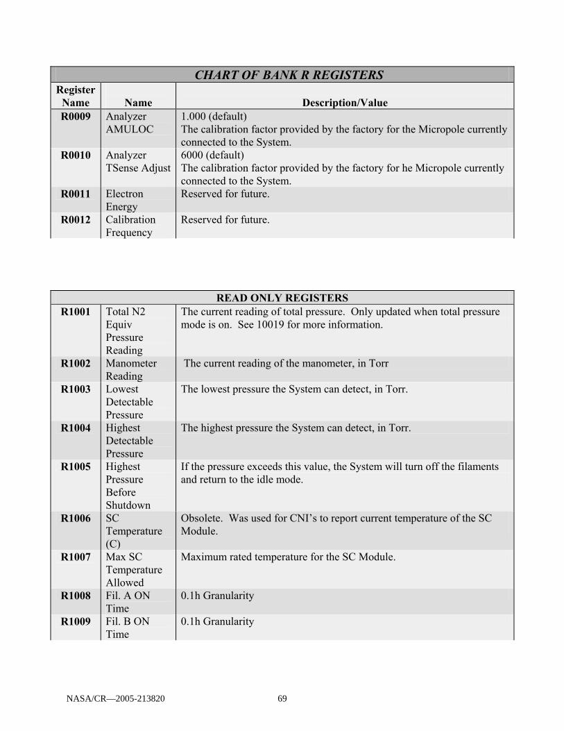
CHART OF BANK R REGISTERS Register
Name
Name
Description/Value R0009 Analyzer
AMULOC 1.000 (default) The calibration factor provided by the factory for the Micropole currently connected to the System.
R0010 Analyzer TSense Adjust
6000 (default) The calibration factor provided by the factory for he Micropole currently connected to the System.
R0011 Electron Energy
Reserved for future.
R0012 Calibration Frequency
Reserved for future.
READ ONLY REGISTERS R1001 Total N2
Equiv Pressure Reading
The current reading of total pressure. Only updated when total pressure mode is on. See 10019 for more information.
R1002 Manometer Reading
The current reading of the manometer, in Torr
R1003 Lowest Detectable Pressure
The lowest pressure the System can detect, in Torr.
R1004 Highest Detectable Pressure
The highest pressure the System can detect, in Torr.
R1005 Highest Pressure Before Shutdown
If the pressure exceeds this value, the System will turn off the filaments and return to the idle mode.
R1006 SC Temperature (C)
Obsolete. Was used for CNI’s to report current temperature of the SC Module.
R1007 Max SC Temperature Allowed
Maximum rated temperature for the SC Module.
R1008 Fil. A ON Time
0.1h Granularity
R1009 Fil. B ON Time
0.1h Granularity
NASA/CR—2005-213820 69

Text Status Bank (BANK T) This bank stores information and messages about the System. It also contains information
that is most conveniently stored as a text.
CHART OF BANK T REGISTERS Register Number
Name
Description/Value
READ ONLY REGISTERS T1001 Manufacturer’s
Name Contains the name of the factory that created the CNI Module.
T1002 CNI’s (or CNI’s) Model Number
Contains the CNI Modules’ model number.
T1003 Serial Number of CNI (or CNI)
Not Used. Reserved for future.
T1004 Firmware Version Contains the Firmware version number. T1005 Last Error Message This will have the last error message. (Note: Communications
errors are not recorded here.) T1006 SC’s Model Number Contains the model number of the SC that is currently connected
to the CNI Module. T1007 Last
Communications Error
This will have the last communications error message.
T1008 SC S/N Reserved for future. T1009 MPA Model Reserved for future. T1010 MPA S/N Reserved for future.
Analog Pressure Bank (BANK N) This bank stores the actual point-by-point readings of the System. The registers are read only
and their contents are an (X,Y) pair of coordinates for the data point read. Unlike Bank A, the register number refers to the number of the data point and not the number of the atomic mass unit.
An (X,Y) pair that has X=0 marks the end of the data points for the scan run. Otherwise, the
X value is the AMU number in the format of ###.#. The Y value is the partial pressure (in Torr) measured at the AMU X. Here is an example:
RN0001{CR} 'give me the data point number 1 AN0001,002.4,1.120E-03 'partial pressure read at AMU 2.4 To use this bank, you need to keep reading data points until you encounter one that has an X
value of 0.For this reason, the length of the packet, and the number of data points in a typical scan, it is NOT recommended that you read this information. See the Optimization of Results section of this manual for more information.
NASA/CR—2005-213820 70

Appendix CFerran Scientific data sheet
NASA/CR—2005-213820 71

SymphonySymphonySymphonySymphony MicropoleTM Mass Spectrometer System
♦ Faster Scan Rates (600 ms / amu)
♦ 10-10 Torr Limit of Detection
♦ 10 parts per billion Sensitivity
♦ 43 eV or 70 eV Ionization Energy Settings
♦ 2x10⁻⁸ atm.cm3/s Minimum Detectable He Leak Rate
♦ New PlasmaGuard Extends Sensor Life
Affordable Gas Measurement, Control and Analysis
New
FSInc. March - 2002
NASA/CR—2005-213820 72
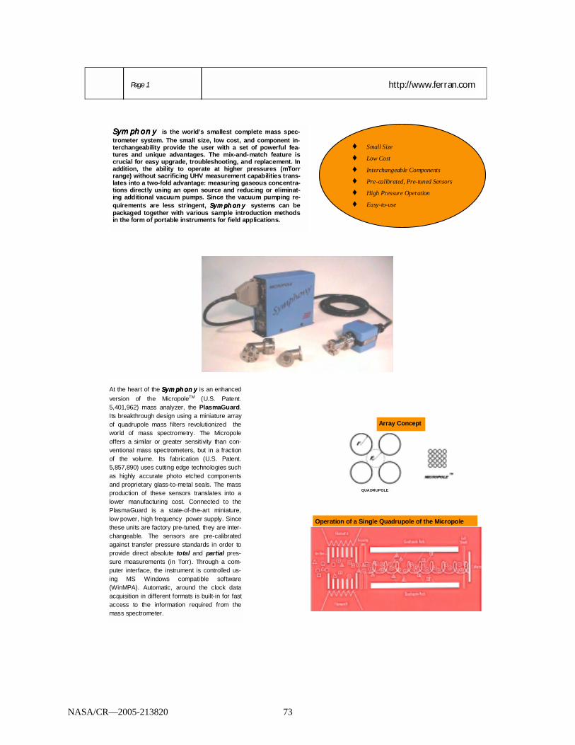
http://www.ferran.com Page 1
SSSSymphonyymphonyymphonyymphony is the world’s smallest complete mass spec-trometer system. The small size, low cost, and component in-terchangeability provide the user with a set of powerful fea-tures and unique advantages. The mix-and-match feature is crucial for easy upgrade, troubleshooting, and replacement. In addition, the ability to operate at higher pressures (mTorr range) without sacrificing UHV measurement capabilities trans-lates into a two-fold advantage: measuring gaseous concentra-tions directly using an open source and reducing or eliminat-ing additional vacuum pumps. Since the vacuum pumping re-quirements are less stringent, SymphonySymphonySymphonySymphony systems can be packaged together with various sample introduction methods in the form of portable instruments for field applications.
At the heart of the Symphony Symphony Symphony Symphony is an enhanced version of the MicropoleTM (U.S. Patent. 5,401,962) mass analyzer, the PlasmaGuard. Its breakthrough design using a miniature array of quadrupole mass filters revolutionized the world of mass spectrometry. The Micropole offers a similar or greater sensitivity than con-ventional mass spectrometers, but in a fraction of the volume. Its fabrication (U.S. Patent. 5,857,890) uses cutting edge technologies such as highly accurate photo etched components and proprietary glass-to-metal seals. The mass production of these sensors translates into a lower manufacturing cost. Connected to the PlasmaGuard is a state-of-the-art miniature, low power, high frequency power supply. Since these units are factory pre-tuned, they are inter-changeable. The sensors are pre-calibrated against transfer pressure standards in order to provide direct absolute total and partial pres-sure measurements (in Torr). Through a com-puter interface, the instrument is controlled us-ing MS Windows compatible software (WinMPA). Automatic, around the clock data acquisition in different formats is built-in for fast access to the information required from the mass spectrometer.
♦ Small Size
♦ Low Cost
♦ Interchangeable Components
♦ Pre-calibrated, Pre-tuned Sensors
♦ High Pressure Operation
♦ Easy-to-use
QUADRUPOLE
Array Concept
Operation of a Single Quadrupole of the Micropole
NASA/CR—2005-213820 73

SymphonySymphonySymphonySymphony Components:
Introducing the PlasmaGuard or shielded Micropole (SMPA) Page 3
Micropole and PlasmaGuard Analyzers: The Micropole (MPA) is a miniature array of quadrupole mass spectrometers designed to operate simultaneously (in parallel). Atoms and molecules are ionized in a single Nier-type ion source following electron impact (EI). Elec-trons are emitted from hot filaments located outside the field of view (main axis) of the quadrupole detector. Using electrostatic lenses, ions are ex-tracted, focused, and injected into individual quadrupole mass filters. Ions with a specific mass-to-charge ratio are filtered by applying a combination of DC and RF voltages to each quadrupole in the array. Filtered ions in each quadrupole are collected on individual Faraday type detectors. All individual detectors contribute to generate a single current signal. A mass spectrum is generated by scanning both AC and DC voltages. A MPA chassis includes a total of 16 rods and 11 electrical pins all secured in a glass-to-metal struc-ture. The structure is sealed in a high temperature oven. The electrostatic lenses, apertures, and plates are made of highly accurate photo etched parts. The sensor construction does not use ceramic parts as is the case with conventional quadrupoles. Therefore, no charging effects are observed. The Symphony system features a more robust version of the Micropole: the PlasmaGuard. It is encapsulated in a stainless steel case for easy handling. The analyzer is also protected by a mesh, on the vacuum fitting, designed to extend the lifetime of the sensor in harsh environments such as plasma processes. Each MPA/PlasmaGuard sensor is delivered with a set of six calibration parameters generated at the factory for fast and easy opera-tion. Two ionization energy settings are built into the Symphony system: 70 eV and 43 eV. While 70 eV is standard, 43 eV setting is used to avoid spectral interferences from doubly charged ions. For example, the water peak at (m/e = 18 amu) is free from 36Ar++ interferences since, 43 eV is just below the second ionization potential of 36Ar. Spectra Converter (SC): The SC includes a pre-tuned RF power supply and a extremely sensitive elec-trometer circuitry. Using a built-in guide pin, the SC is easily connected and secured to the back of the MPA/PlasmaGuard with a connector latch. The combination can be mounted in any orientation. MPAs/PlasmaGuards and SCs are interchangeable for fast and easy replacement, upgrade, and trouble-shooting. Computer Network Interface (CNI): The SC is connected to the CNI using a shielded cable. The cable is immune against surrounding electronic noise from other equipment. The CNI includes the power supplies, the control circuitry and the communications board. All circuits are driven by an internal microcomputer and embedded control soft-ware (firmware). The CNI is directly connected to a PC via RS232, RS485, or TCP/IP serial interfaces. For multiple sensor installations, an RS232/RS485 converter is on board. The CNI is powered by a 24 VDC power supply. Computer Network Logic Interface (CNL): In addition to the CNI circuitry, the CNL includes a board with digital Input/Ouputs and analog output capabilities. A standard Capacitance Diaphragm Gauge (CDG) connection is also available. The additional circuitry enables the user to implement fault detection scenarios using custom decisions based on the data acquired. Automatic operation using external triggers is easily set. Connecting a CDG or other equivalent gauge to the CNL to work in conjunction with the RGA allows the user to implement warning, automatic operation, and sensor protection features.
NASA/CR—2005-213820 74

Catalog Available OnLine Page 4
Micropole and PlasmaGuard Analyzers (MPA and SMPA): - Dimensions: see drawing - Weight: 100 g - Twin-Filament Electron Impact Ion Source - Filaments: Y2O3/Ir (standard), ThO2/Ir, W - 9 Miniature Quadrupole Mass Filters - Mass Filters: 2, 5, 10, 15, 20 mm Long - Faraday Cup Detector - Max. Bake out Temperature: 350 ºC - Max. Operating Temperature: 150 ºC - UHV Compatible: < 10-9 atm.cm3/sec Rate - Mounting Flange: mini-Conflat (standard), NW/KF16 Spectra Converter (SC): - Dimensions: see drawing - Weight: 200 g - RF Power Supplies: 7, 11, 14, or 18 MHz - Factory Pre-Tuned - Interchangeable with any MPA/SMPA Analyzer of the Same Type - Connector Latch for Mounting in Any Orientation Computer Network Interface (CNI): - Dimensions: see drawing - Weight: 750 g - Power Requirements: 24 VDC, 1.5 A - RS232 (50 ft Max.), RS485 (3000 ft Max.) Interfaces - RS232/RS485 Converter - Selectable Baud Rates: 9600, 19600, 38400 - Up to 8 Units can be Daisy-Chained - Built-in standard connections to heated and non heated Capacitance Diaphragm Gauges (See TRIOTRIOTRIOTRIO Brochure) Computer Network Logic Interface (CNL): - Dimensions: see drawing - Weight: 1 kg - Power Requirements: 24 VDC, 1.5 A - RS232 and RS485 Interfaces - RS232/RS485 Converter - Selectable Baud Rates: 9600, 19600, 38400 - Up to 8 Units can be Daisy-Chained - 8 Open Collector Logic Input/Outputs - Standard Connector for non Heated CDGs - 2 Pneumatic Valve Actuators - Optional 3 Analog Outputs (0-1V) Accessories (See Catalog/Price List for Part Numbers): - 24 VDC Power Supply (35 and 65 W) - Micropole Cable (1, 10, 15, 25 ft max.) - RS232 Cable (6, 10, 25, 50 ft Max.) - RS485 Cable (1- 3000 ft Max.) - RS232/RS485 Converter - Isolation Valves (manual and Pneumatic) - Flange Adapters and Mounting Kits - Grounding Strap (3 ft max.)
SymphonySymphonySymphonySymphony Specifications:
MPA
CNL
CNI
SC
SMPA
Micropole Docking Station for 5 Sensors (PAC-05): multi-chamber solution where power supplies, driving electronics, and wires are enclosed in a single platform.
Ferran Scientific Inc. 11558 Sorrento Valley Rd. San Diego, CA 92121 Ph: (858) 792-2332 Fax: (858) 792-0065 Web Site: http://www.ferran.com E-mail: [email protected]
NASA/CR—2005-213820 75

Page 5
(1) Maximum Operating Pressure Minimum Detectable Partial Pressure are specified for molecular Nitrogen (2) X specifies the vacuum flange type: C for 1.33” Conflat and K for NW/KF16
SymphonySymphonySymphonySymphony Options:
Ordering Information: A desired mass range requires specifying a combination of MPA/SMPA and SC. Please contact the Sales department for prices and delivery
For turnkey solutions, please refer to the QuartetQuartetQuartetQuartet brochure available on Ferran.com. The Quartet Quartet Quartet Quartet system, AC line pow-ered, includes SymphonySymphonySymphonySymphony components, data display and control monitor.
Total Process Monitoring and Control Solution ♦ SMPA-5-2/65C: PlasmaGuard (5 mTorr Upper
Pressure limit, 2-65 Amu mass range, mounted on mini Conflat Flange)
♦ SC6-14: 14 MHz Spectra Converter
♦ CNL-06: Computer Logic Interface
♦ PS-03: 24 VDC Power Supply
♦ CA-06-XX: SMPA Shielded Cable
♦ CA-02-YY: RS232 Cable
♦ Control Software (WinMPA2002)
♦ VG-1A (1 Torr CDG; See TRIOTRIOTRIOTRIO Brochure)
♦ V12: Optional Pneumatic valve Contact Sales Offices for Prices XX: Cable Length = 6, 10, 15’ YY: Cable Length = 6, 10’
Shipping Information: Weight ………………………………...………………... 5 kg Approx. Packaging Dimensions …………………………...… 45x40x10 cm
For Miniature, low cost, reliable CDGs, please refer to the TRIOTRIOTRIOTRIO brochure available on Ferran.com .
Mass Range (amu) 2-45 2-45 2-65 2-65 2-100 4-300
Resolution FWHM (amu) 0.5 1.5 0.8 0.9 1 1.5
Maximum Operating Pressure1 (Torr) 1x10⁻³ 1.1x10⁻² 5x10⁻³ 7x10⁻³ 5x10⁻³ 1x10⁻³
Minimum Detectable Partial Pressure1 (Torr) for Slow Scan Updates
10-10 10-10 10-10 10-10 10-10 10-10
Fastest Scan Updates / amu (sec) 0.6 0.6 0.6 0.6 0.6 0.6
Minimum Detectable He Leak Rate (atm.cm3/ sec) 2x10⁻⁸ 2x10⁻⁸ 2x10⁻⁸ 2x10⁻⁷ 2x10⁻⁸ 2x10⁻⁸
PlasmaGuard (SMPA) SMPA-1-2/45-X2 SMPA-11-2/45-X SMPA-5-2/65-X SMPA-7-2/65-X SMPA-5-2/100-X SMPA-1-4/300-X
Micropole Analyzer (MPA) MPA6-1-2/45-X MPA6-11-2/45-X MPA6-5-2/65-X MPA6-7-2/65-X MPA6-5-2/100-X MPA6-1-4/300-X
Spectra Converter (SC) SC6-18 SC6-18 SC6-14 SC6-14 SC6-11 SC6-07
NASA/CR—2005-213820 76

Page 6 http://www.ferran.com
WinMPATM Control Software:
Table Mode
Trend Mode
Analog Scan
Histogram
Leak Mode
Deviation Graph
Multi-chamber Control
SSSSymphonyymphonyymphonyymphony is controlled using WinMPA, a Windows application developed by Ferran Scientific Inc. In addition to the communication protocols, WinMPA includes data acquisition, display, and file handling capa-bilities. When executed for the first time, WinMPA performs a three-step configuration procedure. 1. ANA-LYZER CONFIG.: consists of entering the calibration parameters of each MPA/SMPA. The parameters of the analyzer are stored under a name (e.g. serial number) specified under NEW ANALYZER. 2. SYSTEM CONFIG.: a SYSTEM comprises a MPA/SMPA, a SC, and CNI/CNL. Under NEW SYSTEM, the model and the serial number of the SC and CNI/CNL are entered. The MPA/SMPA is selected from a pull-down menu showing all analyzers configured under ANALYZER CONFIG. 3. COMM CONFIG. consists of linking a SYSTEM to a communication port of the PC. After setting the baud rate, the serial interface (RS232 or RS485) is selected. For multiple sensor applications, each SYSTEM has an address (0 through 32). A SYSTEM STATUS window enables the user to control, open graphs, save data, and generate process recipes for each SYSTEM independently.
- Compatible with Windows XP, 2000, Me, NT 4.0, 95/98, 3.1/3.11 - PC Requirements: 66 MHz, 16 MB RAM. Higher specifications are required for multiple analyzer installations. - Embedded demo mode - Capture of all data all the time in temporary files - Automatic 24/7 data capture and file naming - Binary and ASCII data file formats - Dynamic Data Exchange (DDE) links with spread sheet software. - Optional TCP/IP protocol - Data display in multiple, simultaneous BAR, TREND, ANALOG, TABLE, and DEVIATION graphs. - Torr, Pascal, Bar, and PPM Units. - Linear and Logarithmic Scales - LEDs to show status of Input/Outputs - Monitor and display signals from complementary gauges such as CDGs. - Custom warnings following drifts from set tolerances - Storage of process control recipes - Statistical process control (SPC) incorporated into recipes - Deviation graphs showing drifts from “ideal” runs - Event-driven full automated operation and data storage - Jump/Continuous Scans with or without Total Pressure measure-ment - Pre-set scan speed mode and graph recipes - Sensor accumulated hours of operation - Helium leak mode with progressive display graph and audible warning
WinMPA Highlights
NASA/CR—2005-213820 77

Enhancing Productivity in Manufacturing Facilities Page 7
SymphonySymphonySymphonySymphony Typical ApplicationsTypical ApplicationsTypical ApplicationsTypical Applications
Semiconductor Chip Manufacturing: ♦ Photoresist detection
♦ Moisture & contaminant detection in wafer Handling chambers of cluster tools
♦ Wet clean recovery after PM cycles
♦ Leakback test and leak troubleshooting
♦ Process monitoring and control
♦ Tool diagnostics and characterization
General Residual Gas Analysis: ♦ Vacuum diagnosis from UHV to low vacuum
♦ Troubleshooting leaks
♦ Monitoring and control of contaminants
♦ Helium leak detection
Space Research: ♦ Hazardous gas detection
♦ Life support and leak detection onboard Space Station
♦ Planetary and moon Exploration: Mars, Eu-ropa
R&D: ♦ Multi-sensor deployment
♦ Remote operation
♦ Particle accelerators
♦ Synchrotrons
Industrial Vacuum Coating: ♦ Vacuum and optical coating
♦ Vacuum furnaces
♦ Glass coating
♦ Preventive maintenance
♦ Cryogenic pumps performance
Environmental Monitoring: ♦ Detection of volatile organic compounds
(VOCs)
♦ Abatement monitoring
♦ Oceanography applications
NASA/CR—2005-213820 78

Phone: (858) 792-2332 Fax: (858) 792-0065
E-mail: [email protected]
Http://www.ferran.com 11558 Sorrento Valley rd.
San Diego, CA 92121 U.S.A
Since it was founded in 1989, Ferran Scientific Inc. has established itself as the world leader in miniature, low cost pressure measurement and gas analysis. Using patented innovations in vacuum technology, Ferran Scien-tific Inc. was able to respond to pressing needs for affordable in-situ gas instrumentation. Upon its intro-duction, the Micropole mass spec-trometer has enjoyed world wide acceptance and success as one of the technological breakthroughs in 30 years of quadrupole mass filter designs. The Micropole continues to be a workhorse in affordable mass spectrometry with an impressive in-stalled base in a variety of indus-tries. The Micropole, in its newly re-leased SymphonySymphonySymphonySymphony system, is the world’s smallest complete mass spectrometer system. These con-sumable sensor type instruments have provided lower cost of owner-ship in numerous applications. Using its expertise in miniaturization and mass production employing cutting edge technological tools, Ferran Sci-entific Inc. is able to manufacture instruments such as mass spec-trometers and pressure gauges for a wide range of usage. The inter-changeability of sensors and elec-tronics adds an unprecedented plug-and-play concept for easy trouble-shooting, upgrade, and replace-ment. The company’s turnkey solu-tions enable the user to minimize the installation time and rapidly ex-tract gas pressure and analysis in-formation.
Affordable Gas Measurement, Control and Analysis
NASA/CR—2005-213820 79

This publication is available from the NASA Center for AeroSpace Information, 301–621–0390.
REPORT DOCUMENTATION PAGE
2. REPORT DATE
19. SECURITY CLASSIFICATION OF ABSTRACT
18. SECURITY CLASSIFICATION OF THIS PAGE
Public reporting burden for this collection of information is estimated to average 1 hour per response, including the time for reviewing instructions, searching existing data sources,gathering and maintaining the data needed, and completing and reviewing the collection of information. Send comments regarding this burden estimate or any other aspect of thiscollection of information, including suggestions for reducing this burden, to Washington Headquarters Services, Directorate for Information Operations and Reports, 1215 JeffersonDavis Highway, Suite 1204, Arlington, VA 22202-4302, and to the Office of Management and Budget, Paperwork Reduction Project (0704-0188), Washington, DC 20503.
NSN 7540-01-280-5500 Standard Form 298 (Rev. 2-89)Prescribed by ANSI Std. Z39-18298-102
Form Approved
OMB No. 0704-0188
12b. DISTRIBUTION CODE
8. PERFORMING ORGANIZATION REPORT NUMBER
5. FUNDING NUMBERS
3. REPORT TYPE AND DATES COVERED
4. TITLE AND SUBTITLE
6. AUTHOR(S)
7. PERFORMING ORGANIZATION NAME(S) AND ADDRESS(ES)
11. SUPPLEMENTARY NOTES
12a. DISTRIBUTION/AVAILABILITY STATEMENT
13. ABSTRACT (Maximum 200 words)
14. SUBJECT TERMS
17. SECURITY CLASSIFICATION OF REPORT
16. PRICE CODE
15. NUMBER OF PAGES
20. LIMITATION OF ABSTRACT
Unclassified Unclassified
Final Contractor Report
Unclassified
1. AGENCY USE ONLY (Leave blank)
10. SPONSORING/MONITORING AGENCY REPORT NUMBER
9. SPONSORING/MONITORING AGENCY NAME(S) AND ADDRESS(ES)
National Aeronautics and Space AdministrationWashington, DC 20546–0001
Available electronically at http://gltrs.grc.nasa.gov
November 2005
NASA CR—2005–213820
E–15178
WBS–22–101–42–02NAS3–01164
85
Identification and Quantitative Measurements of Chemical Species byMass Spectrometry
Mark A. Zondlo and David S. Bomse
Mass spectrometers; Gas analysis; Gas chromatography; Quadrupoles
Unclassified -UnlimitedSubject Category: 35
Southwest Sciences, Inc.51570 Pacheco Street, Suite E–11Santa Fe, New Mexico 87505
Project Manager, Karen J. Weiland, Exploration Systems Division, NASA Glenn Research Center, organization codePTO, 216–433–3623.
The development of a miniature gas chromatograph/mass spectrometer system for the measurement of chemical speciesof interest to combustion is described. The completed system is a fully-contained, automated instrument consisting of asampling inlet, a small-scale gas chromatograph, a miniature, quadrupole mass spectrometer, vacuum pumps, andsoftware. A pair of computer-driven valves controls the gas sampling and introduction to the chromatographic column.The column has a stainless steel exterior and a silica interior, and contains an adsorbent of divinylbenzene that is used toseparate organic species. The detection system is based on a quadrupole mass spectrometer consisting of a micropolearray, electrometer, and a computer interface. The vacuum system has two miniature pumps to maintain the low pressureneeded for the mass spectrometer. A laptop computer uses custom software to control the entire system and collect thedata. In a laboratory demonstration, the system separated calibration mixtures containing 1000 ppm of alkanes and alkenes.

