identification cards — integrated circuit cardsed2.0}en.pdf · identification cards —...
TRANSCRIPT

Reference numberISO/IEC 7816-4:2005(E)
© ISO/IEC 2005
INTERNATIONAL STANDARD
ISO/IEC7816-4
Second edition2005-01-15
Identification cards — Integrated circuit cards — Part 4: Organization, security and commands for interchange
Cartes d'identification — Cartes à circuit intégré —
Partie 4: Organisation, sécurité et commandes pour les échanges

ISO/IEC 7816-4:2005(E)
PDF disclaimer This PDF file may contain embedded typefaces. In accordance with Adobe's licensing policy, this file may be printed or viewed but shall not be edited unless the typefaces which are embedded are licensed to and installed on the computer performing the editing. In downloading this file, parties accept therein the responsibility of not infringing Adobe's licensing policy. The ISO Central Secretariat accepts no liability in this area.
Adobe is a trademark of Adobe Systems Incorporated.
Details of the software products used to create this PDF file can be found in the General Info relative to the file; the PDF-creation parameters were optimized for printing. Every care has been taken to ensure that the file is suitable for use by ISO member bodies. In the unlikely event that a problem relating to it is found, please inform the Central Secretariat at the address given below.
© ISO/IEC 2005 All rights reserved. Unless otherwise specified, no part of this publication may be reproduced or utilized in any form or by any means, electronic or mechanical, including photocopying and microfilm, without permission in writing from either ISO at the address below or ISO's member body in the country of the requester.
ISO copyright office Case postale 56 • CH-1211 Geneva 20 Tel. + 41 22 749 01 11 Fax + 41 22 749 09 47 E-mail [email protected] Web www.iso.org
Published in Switzerland
ii © ISO/IEC 2005 – All rights reserved

ISO/IEC 7816-4:2005(E)
© ISO/IEC 2005 — All rights reserved iii
Contents Page
Foreword............................................................................................................................................................ iv Introduction ........................................................................................................................................................ v 1 Scope...................................................................................................................................................... 1 2 Normative references ........................................................................................................................... 1 3 Terms and definitions........................................................................................................................... 2 4 Symbols and abbreviated terms.......................................................................................................... 5 5 Organization for interchange............................................................................................................... 7 5.1 Command-response pairs.................................................................................................................... 7 5.2 Data objects......................................................................................................................................... 13 5.3 Structures for applications and data ................................................................................................ 17 5.4 Security architecture .......................................................................................................................... 22 6 Secure messaging .............................................................................................................................. 28 6.1 SM fields and SM data objects .......................................................................................................... 28 6.2 Basic SM data objects ........................................................................................................................ 29 6.3 Auxiliary SM data objects................................................................................................................... 31 6.4 SM impact on command-response pairs.......................................................................................... 35 7 Commands for interchange ............................................................................................................... 36 7.1 Selection .............................................................................................................................................. 36 7.2 Data unit handling............................................................................................................................... 39 7.3 Record handling.................................................................................................................................. 41 7.4 Data object handling........................................................................................................................... 47 7.5 Basic security handling...................................................................................................................... 50 7.6 Transmission handling....................................................................................................................... 57 8 Application-independent card services............................................................................................ 57 8.1 Card identification............................................................................................................................... 58 8.2 Application identification and selection ........................................................................................... 61 8.3 Selection by path ................................................................................................................................ 64 8.4 Data retrieval ....................................................................................................................................... 65 8.5 Data element retrieval......................................................................................................................... 65 8.6 Card-originated byte strings.............................................................................................................. 67 Annex A (informative) Examples of object identifiers and tag allocation schemes.................................. 69 Annex B (informative) Examples of secure messaging................................................................................ 71 Annex C (informative) Examples of AUTHENTICATE functions by GENERAL AUTHENTICATE commands........ 78 Annex D (informative) Application identifiers using issuer identification numbers ................................. 82 Bibliography ..................................................................................................................................................... 83

ISO/IEC 7816-4:2005(E)
iv © ISO/IEC 2005 — All rights reserved
Foreword
ISO (the International Organization for Standardization) and IEC (the International Electrotechnical Commission) form the specialized system for worldwide standardization. National bodies that are members of ISO or IEC participate in the development of International Standards through technical committees established by the respective organization to deal with particular fields of technical activity. ISO and IEC technical committees collaborate in fields of mutual interest. Other international organizations, governmental and non-governmental, in liaison with ISO and IEC, also take part in the work. In the field of information technology, ISO and IEC have established a joint technical committee, ISO/IEC JTC 1.
International Standards are drafted in accordance with the rules given in the ISO/IEC Directives, Part 2.
The main task of the joint technical committee is to prepare International Standards. Draft International Standards adopted by the joint technical committee are circulated to national bodies for voting. Publication as an International Standard requires approval by at least 75 % of the national bodies casting a vote.
ISO/IEC 7816-4 was prepared by Joint Technical Committee ISO/IEC JTC 1, Information technology, Subcommittee SC 17, Cards and personal identification.
This second edition cancels and replaces the first edition (ISO/IEC 7816-4:1995), and incorporates material extracted from ISO/IEC 7816-5:1994, ISO/IEC 7816-6:1996, ISO/IEC 7816-8:1999 and ISO/IEC 7816-9:2000. It also incorporates the Amendment ISO/IEC 7816-4:1995/Amd.1:1997.
In addition, material has been extracted from the first edition and moved to the third edition of ISO/IEC 7816-3, so that the transmission protocols T=0 and T=1 are now present only in ISO/IEC 7816-3, no longer in ISO/IEC 7816-4.
ISO/IEC 7816 consists of the following parts, under the general title Identification cards — Integrated circuit cards:
Part 1: Cards with contacts: Physical characteristics
Part 2: Cards with contacts: Dimensions and location of the contacts
Part 3: Cards with contacts: Electrical interface and transmission protocols
Part 4: Organization, security and commands for interchange
Part 5: Registration of application providers
Part 6: Interindustry data elements for interchange
Part 7: Interindustry commands for Structured Card Query Language (SCQL)
Part 8: Commands for security operations
Part 9: Commands for card management
Part 10: Cards with contacts: Electronic signals and answer to reset for synchronous cards
Part 11: Personal verification through biometric methods
Part 12: Cards with contacts: USB electrical interface and operating procedures
Part 15: Cryptographic information application
ISO/IEC 7816-4:2005(E)
© ISO/IEC 2005 — All rights reserved v
Introduction
ISO/IEC 7816 is a series of standards specifying integrated circuit cards and the use of such cards for interchange. These cards are identification cards intended for information exchange negotiated between the outside world and the integrated circuit in the card. As a result of an information exchange, the card delivers information (computation result, stored data), and / or modifies its content (data storage, event memorization).
Five parts are specific to cards with galvanic contacts and three of them specify electrical interfaces.
• ISO/IEC 7816-1 specifies physical characteristics for cards with contacts.
• ISO/IEC 7816-2 specifies dimensions and location of the contacts.
• ISO/IEC 7816-3 specifies electrical interface and transmission protocols for asynchronous cards.
• ISO/IEC 7816-10 specifies electrical interface and answer to reset for synchronous cards.
• ISO/IEC 7816-12 specifies electrical interface and operating procedures for USB cards.
All the other parts are independent from the physical interface technology. They apply to cards accessed by contacts and / or by radio frequency.
• ISO/IEC 7816-4 specifies organization, security and commands for interchange.
• ISO/IEC 7816-5 specifies registration of application providers.
• ISO/IEC 7816-6 specifies interindustry data elements for interchange.
• ISO/IEC 7816-7 specifies commands for structured card query language.
• ISO/IEC 7816-8 specifies commands for security operations.
• ISO/IEC 7816-9 specifies commands for card management.
• ISO/IEC 7816-11 specifies personal verification through biometric methods.
• ISO/IEC 7816-15 specifies cryptographic information application.
ISO/IEC 10536 [13] specifies access by close coupling. ISO/IEC 14443 [15] and ISO/IEC 15693 [17] specify access by radio frequency. Such cards are also known as contactless cards.
ISO and IEC draw attention to the fact that it is claimed that compliance with this document may involve the use of the following patents and the foreign counterparts.
JPN 2033906, Portable electronic device
JPN 2557838, Integrated circuit card
JPN 2537199, Integrated circuit card
JPN 2856393, Portable electronic device
JPN 2137026, Portable electronic device
JPN 2831660, Portable electronic device
DE 198 55 596, Portable microprocessor-assisted data carrier that can be used with or without contacts
ISO and IEC take no position concerning the evidence, validity and scope of these patent rights.
The holders of these patent rights have assured ISO and IEC that they are willing to negotiate licences under reasonable and non-discriminatory terms and conditions with applications throughout the world. In this respect,

ISO/IEC 7816-4:2005(E)
vi © ISO/IEC 2005 — All rights reserved
the statements of the holders of these patent rights are registered with ISO and IEC. Information may be obtained from:
Contact Patent details
Toshiba Corporation Intellectual Property Division 1-1, Shibaura 1-Chome Minato-ku, Tokyo 105-8001, Japan
JPN 2033906 (priority date: 1986-02-18; publication date: 1996-03-19), FRA 8614996, KOR 44664
JPN 2557838 (priority date: 1986-02-18; publication date: 1996-09-05), FRA 8700343, GER 3700504, KOR 42243, USA 4841131
JPN 2537199 (priority date: 1986-06-20; publication date: 1996-07-08), FRA 8708646, FRA 8717770, USA 4833595, USA 4901276
JPN 2856393 (priority date: 1987-02-17; publication date: 1998-11-27), FRA 8801887, KOR 43929, USA 4847803
JPN 2137026 (priority date: 1987-02-20; publication date: 1998-06-26), JPN 3054119, FRA 8802046, KOR 44393, USA 4891506
JPN 2831660 (priority date: 1988-08-26; publication date: 1998-09-25), FRA 8911249, KOR 106290, USA 4988855
Orga Kartensysteme Gmbh Am Hoppenhof 33 D-33104 Paderborn Germany
DE 198 55 596 (priority date: 1998-12-02; publication date: 2000-06-29)
Applications pending in Europe, Russia, Japan, China, USA, Brazil, Australia

INTERNATIONAL STANDARD ISO/IEC 7816-4:2005(E)
© ISO/IEC 2005 — All rights reserved 1
Identification cards — Integrated circuit cards —
Part 4: Organization, security and commands for interchange
1 Scope
This part of ISO/IEC 7816 specifies
contents of command-response pairs exchanged at the interface,
means of retrieval of data elements and data objects in the card,
structures and contents of historical bytes to describe operating characteristics of the card,
structures for applications and data in the card, as seen at the interface when processing commands,
access methods to files and data in the card,
a security architecture defining access rights to files and data in the card,
means and mechanisms for identifying and addressing applications in the card,
methods for secure messaging,
access methods to the algorithms processed by the card. It does not describe these algorithms.
It does not cover the internal implementation within the card or the outside world.
This part of ISO/IEC 7816 is independent from the physical interface technology. It applies to cards accessed by one or more of the following methods: contacts, close coupling and radio frequency.
2 Normative references
The following referenced documents are indispensable for the application of this document. For dated refer-ences, only the edition cited applies. For undated references, the latest edition of the referenced document (including any amendments) applies.
ISO/IEC 7816-3, Identification cards — Integrated circuit cards — Part 3: Cards with contacts: Electrical interface and transmission protocols
ISO/IEC 7816-6, Identification cards — Integrated circuit cards — Part 6: Interindustry data elements for interchange
ISO/IEC 8825-1:2002, Information technology — ASN.1 encoding rules: Specification of Basic Encoding Rules (BER), Canonical Encoding Rules (CER) and Distinguished Encoding Rules (DER)

ISO/IEC 7816-4:2005(E)
2 © ISO/IEC 2005 — All rights reserved
3 Terms and definitions
For the purposes of this document, the following terms and definitions apply.
3.1 access rule data element containing an access mode referring to an action and security conditions to fulfil before acting
3.2 Answer-to-Reset file optional EF indicating operating characteristics of the card
3.3 application structures, data elements and program modules needed for performing a specific functionality
3.4 application DF structure hosting an application in a card
3.5 application identifier data element (up to sixteen bytes) that identifies an application
3.6 application label data element for use at the man-machine interface
3.7 application provider entity providing the components that make up an application in the card
3.8 application template set of application-relevant data objects including one application identifier data object
3.9 asymmetric cryptographic technique cryptographic technique that uses two related operations: a public operation defined by public numbers or by a public key and a private operation defined by private numbers or by a private key (the two operations have the property that, given the public operation, it is computationally infeasible to derive the private operation)
3.10 certificate digital signature binding a particular person or object and its associated public key (the entity issuing the certificate also acts as tag allocation authority with respect to the data elements in the certificate)
3.11 command-response pair set of two messages at the interface: a command APDU followed by a response APDU in the opposite direction
3.12 data element item of information seen at the interface for which are specified a name, a description of logical content, a format and a coding

ISO/IEC 7816-4:2005(E)
© ISO/IEC 2005 — All rights reserved 3
3.13 data object information seen at the interface consisting of the concatenation of a mandatory tag field, a mandatory length field and a conditional value field
3.14 data unit the smallest set of bits that can be unambiguously referenced within an EF supporting data units
3.15 dedicated file structure containing file control information and, optionally, memory available for allocation
3.16 DF name data element (up to sixteen bytes) that uniquely identifies a DF in the card
3.17 digital signature data appended to, or cryptographic transformation of, a data string that proves the origin and the integrity of the data string and protects against forgery, e.g., by the recipient of the data string
3.18 directory file optional EF containing a list of applications supported by the card and optional related data elements
3.19 elementary file set of data units or records or data objects sharing the same file identifier and the same security attribute(s)
3.20 file structure for application and / or data in the card, as seen at the interface when processing commands
3.21 file identifier data element (two bytes) used to address a file
3.22 header list concatenation of pairs of tag field and length field without delimitation
3.23 identification card card identifying its holder and issuer, which may carry data required as input for the intended use of the card and for transactions based thereon [ISO/IEC 7810[2]]
3.24 internal elementary file EF for storing data interpreted by the card
3.25 key sequence of symbols controlling a cryptographic operation (e.g., encipherment, decipherment, a private or a public operation in a dynamic authentication, signature production, signature verification)

ISO/IEC 7816-4:2005(E)
4 © ISO/IEC 2005 — All rights reserved
3.26 master file unique DF representing the root in a card using a hierarchy of DFs
3.27 offset number sequentially referencing a data unit in an EF supporting data units, or a byte in a record
3.28 parent file DF immediately preceding a given file within a hierarchy of DFs
3.29 password data that may be required by the application to be presented to the card by its user for authentication purpose
3.30 path concatenation of file identifiers without delimitation
3.31 private key that key of an entity's asymmetric key pair that should only be used by that entity [ISO/IEC 9798-1[8]]
3.32 provider authority who has or who obtained the right to create a DF in the card
3.33 public key that key of an entity's asymmetric key pair that can be made public [ISO/IEC 9798-1[8]]
3.34 record string of bytes referenced and handled by the card within an EF supporting records
3.35 record identifier number used to reference one or more records within an EF supporting records
3.36 record number sequential number that uniquely identifies each record within an EF supporting records
3.37 registered application provider identifier data element (five bytes) that uniquely identifies an application provider
3.38 secret key key used with symmetric cryptographic techniques by a set of specified entities [ISO/IEC 11770-3[14]]
3.39 secure messaging set of means for cryptographic protection of [parts of] command-response pairs

ISO/IEC 7816-4:2005(E)
© ISO/IEC 2005 — All rights reserved 5
3.40 security attribute condition of use of objects in the card including stored data and data processing functions, expressed as a data element containing one or more access rules
3.41 security environment set of components required by an application in the card for secure messaging or for security operations
3.42 symmetric cryptographic technique cryptographic technique using the same secret key for both the originator's and the recipient's operation (without the secret key, it is computationally infeasible to compute either operation)
3.43 tag list concatenation of tag fields without delimitation
3.44 template set of BER-TLV data objects forming the value field of a constructed BER-TLV data object
3.45 working elementary file EF for storing data not interpreted by the card
4 Symbols and abbreviated terms
AID application identifier
APDU application protocol data unit
ARR access rule reference
ASN.1 abstract syntax notation one (see ISO/IEC 8825-1)
AT control reference template for authentication
ATR Answer-to-Reset
BER basic encoding rules of ASN.1 (see ISO/IEC 8825-1)
CCT control reference template for cryptographic checksum
CLA class byte
CRT control reference template
CT control reference template for confidentiality
DF dedicated file
DIR directory
DST control reference template for digital signature
EF elementary file
EF.ARR access rule reference file
ISO/IEC 7816-4:2005(E)
6 © ISO/IEC 2005 — All rights reserved
EF.ATR Answer-to-Reset file
EF.DIR directory file
FCI file control information
FCP file control parameter
FMD file management data
HT control reference template for hash-code
INS instruction byte
KAT control reference template for key agreement
Lc field length field for coding the number Nc
LCS byte life cycle status byte
Le field length field for coding the number Ne
MF master file
Nc number of bytes in the command data field
Ne maximum number of bytes expected in the response data field
Nr number of bytes in the response data field
PIX proprietary application identifier extension
P1-P2 parameter bytes (inserted for clarity, the dash is not significant)
RFU reserved for future use
RID registered application provider identifier
SC security condition
SCQL structured card query language
SE security environment
SEID byte security environment identifier byte
SM secure messaging
SW1-SW2 status bytes (inserted for clarity, the dash is not significant)
(SW1-SW2) value of the concatenation of the bytes SW1 and SW2 (the first byte is the most significant byte)
TLV tag, length, value
{T-L-V} data object (inserted for clarity, the dashes and curly brackets are not significant)
'XX' notation using the hexadecimal digits '0' to '9' and 'A' to 'F', equal to XX to the base 16

ISO/IEC 7816-4:2005(E)
© ISO/IEC 2005 — All rights reserved 7
5 Organization for interchange
For organizing interchange, this clause specifies the following basic features. 1) Command-response pairs 2) Data objects 3) Structures for applications and data 4) Security architecture
5.1 Command-response pairs
Table 1 shows a command-response pair, namely a command APDU followed by a response APDU in the opposite direction (see ISO/IEC 7816-3). There shall be no interleaving of command-response pairs across the interface, i.e., the response APDU shall be received before initiating another command-response pair.
Table 1 — Command-response pair Field Description Number of bytes
Class byte denoted CLA 1 Instruction byte denoted INS 1
Command header
Parameter bytes denoted P1-P2 2 Lc field Absent for encoding Nc = 0, present for encoding Nc > 0 0, 1 or 3
Command data field Absent if Nc = 0, present as a string of Nc bytes if Nc > 0 Nc Le field Absent for encoding Ne = 0, present for encoding Ne > 0 0, 1, 2 or 3
Response data field Absent if Nr = 0, present as a string of Nr bytes if Nr > 0 Nr (at most Ne) Response trailer Status bytes denoted SW1-SW2 2
In any command-response pair comprising both Lc and Le fields (see ISO/IEC 7816-3), short and extended length fields shall not be combined: either both of them are short, or both of them are extended.
If the card explicitly states its capability of handling “extended Lc and Le fields” (see Table 88, third software function table) in the historical bytes (see 8.1.1) or in EF.ATR (see 8.2.1.1), then the card handles short and extended length fields. Otherwise (default value), the card handles only short length fields.
Nc denotes the number of bytes in the command data field. The Lc field encodes Nc. If the Lc field is absent, then Nc is zero. A short Lc field consists of one byte not set to '00'.
• From '01' to 'FF', the byte encodes Nc from one to 255. An extended Lc field consists of three bytes: one byte set to '00' followed by two bytes not set to '0000'.
• From '0001' to 'FFFF', the two bytes encode Nc from one to 65 535.
Ne denotes the maximum number of bytes expected in the response data field. The Le field encodes Ne. If the Le field is absent, then Ne is zero. A short Le field consists of one byte with any value.
• From '01' to 'FF', the byte encodes Ne from one to 255. • If the byte is set to '00', then Ne is 256.
An extended Le field consists of either three bytes (one byte set to '00' followed by two bytes with any value) if the Lc field is absent, or two bytes (with any value) if an extended Lc field is present. • From '0001' to 'FFFF', the two bytes encode Ne from one to 65 535. • If the two bytes are set to '0000', then Ne is 65 536.
Nr denotes the number of bytes in the response data field. Nr shall be less than or equal to Ne. Therefore in any command-response pair, the absence of Le field is the standard way for receiving no response data field. If the Le field contains only bytes set to '00', then Ne is maximum, i.e., within the limit of 256 for a short Le field, or 65 536 for an extended Le field, all the available bytes should be returned.

ISO/IEC 7816-4:2005(E)
8 © ISO/IEC 2005 — All rights reserved
If the process is aborted, then the card may become unresponsive. However if a response APDU occurs, then the response data field shall be absent and SW1-SW2 shall indicate an error.
P1-P2 indicates controls and options for processing the command. A parameter byte set to '00' generally provides no further qualification. There is no other general convention for encoding the parameter bytes.
General conventions are specified hereafter for encoding the class byte denoted CLA (see 5.1.1), the instruction byte denoted INS (see 5.1.2) and the status bytes denoted SW1-SW2 (see 5.1.3). In those bytes, the RFU bits shall be set to 0 unless otherwise specified.
5.1.1 Class byte
CLA indicates the class of the command. Due to specifications in ISO/IEC 7816-3, the value 'FF' is invalid. Bit 8 of CLA distinguishes between the interindustry class and the proprietary class.
Bit 8 set to 0 indicates the interindustry class. The values 000x xxxx and 01xx xxxx are specified hereafter. The values 001x xxxx are reserved for future use by ISO/IEC JTC 1/SC 17.
Table 2 specifies 000x xxxx as the first interindustry values. • Bits 8, 7 and 6 are set to 000. • Bit 5 controls command chaining (see 5.1.1.1). • Bits 4 and 3 indicate secure messaging (see 6). • Bits 2 and 1 encode a logical channel number from zero to three (see 5.1.1.2).
Table 2 — First interindustry values of CLA b8 b7 b6 b5 b4 b3 b2 b1 Meaning 0 0 0 x - - - - Command chaining control (see 5.1.1.1) 0 0 0 0 - - - - — The command is the last or only command of a chain 0 0 0 1 - - - - — The command is not the last command of a chain 0 0 0 - x x - - Secure messaging indication 0 0 0 - 0 0 - - — No SM or no indication 0 0 0 - 0 1 - - — Proprietary SM format 0 0 0 - 1 0 - - — SM according to 6, command header not processed according to 6.2.3.10 0 0 - 1 1 - - — SM according to 6, command header authenticated according to 6.2.3.10 0 0 - - - x x Logical channel number from zero to three (see 5.1.1.2)
Table 3 specifies 01xx xxxx as further interindustry values. • Bits 8 and 7 are set to 01. • Bit 6 indicates secure messaging (see 6). • Bit 5 controls command chaining (see 5.1.1.1). • Bits 4 to 1 encode a number from zero to fifteen; this number plus four is the logical channel number
from four to nineteen (see 5.1.1.2).
Table 3 — Further interindustry values of CLA b8 b7 b6 b5 b4 b3 b2 b1 Meaning 0 1 x - - - - - Secure messaging indication 0 1 0 - - - - - — No SM or no indication 0 1 1 - - - - - — SM according to 6, command header not processed according to 6.2.3.10 1 - x - - - - Command chaining control (see 5.1.1.1) 0 1 - 0 - - - - — The command is the last or only command of a chain 0 1 - 1 - - - - — The command is not the last command of a chain 0 1 - - x x x x Logical channel number from four to nineteen (see 5.1.1.2)
Bit 8 set to 1 indicates the proprietary class, except for the value 'FF' which is invalid. The application-context defines the other bits.

ISO/IEC 7816-4:2005(E)
© ISO/IEC 2005 — All rights reserved 9
5.1.1.1 Command chaining
This clause specifies a mechanism whereby in the interindustry class, consecutive command-response pairs can be chained. The mechanism may be used when executing a multi-step process, e.g., transmitting a data string too long for a single command.
If the card supports the mechanism, then it shall indicate it (see Table 88, third software function table) in the historical bytes (see 8.1.1) or in EF.ATR (see 8.2.1.1).
This document specifies the card behaviour only in the case where, once initiated, a chain is terminated before initiating a command-response pair not part of the chain. Otherwise the card behaviour is not specified.
For chaining in the interindustry class, bit 5 of CLA shall be used while the other seven bits are constant.
If bit 5 is set to 0, then the command is the last or only command of a chain.
If bit 5 is set to 1, then the command is not the last command of a chain.
In response to a command that is not the last command of a chain, SW1-SW2 set to '9000' means that the process has been completed so far; warning indications are prohibited (see 5.1.3); moreover, the following specific error conditions may occur.
If SW1-SW2 is set to '6883', then the last command of the chain is expected.
If SW1-SW2 is set to '6884', then command chaining is not supported.
5.1.1.2 Logical channels
This clause specifies a mechanism whereby in the interindustry class, command-response pairs can refer to logical channels.
If the card supports the mechanism, then it shall indicate the maximum number of available channels (see Table 88, third software function table) in the historical bytes (see 8.1.1) or in EF.ATR (see 8.2.1.1).
If the indicated number is four or less, then only Table 2 applies.
If the indicated number is five or more, then Table 3 also applies.
For referring to logical channels in the interindustry class, the following rules apply.
CLA encodes the channel number of the command-response pair.
The basic channel shall be permanently available, i.e., it cannot be closed. Its channel number is zero.
Cards not supporting the mechanism (default value) shall use only the basic channel.
Any other channel shall be opened by completion of either a SELECT command (see 7.1.1) where CLA encodes a channel number not yet in use, or a MANAGE CHANNEL command with open function (see 7.1.2).
Any other channel can be closed by the completion of a MANAGE CHANNEL command with close function. After closing, the channel shall be available for re-use.
Only one channel shall be active at a time. The use of logical channels does not remove the prohibition of interleaving command-response pairs across the interface, i.e., the response APDU shall be received before initiating another command-response pair (see 5.1).
If not explicitly excluded by the file descriptor byte (see Table 14), more than one channel may be opened to the same structure (see 5.3), i.e., to a DF, possibly an application DF, and also possibly to an EF.
Each logical channel has its own security status (see 5.4). The way to share a security status is outside the scope of this document.

ISO/IEC 7816-4:2005(E)
10 © ISO/IEC 2005 — All rights reserved
5.1.2 Instruction byte
INS indicates the command to process. Due to specifications in ISO/IEC 7816-3, the values '6X' and '9X' are invalid.
Table 4 lists all the commands specified in ISO/IEC 7816 at the time of publication. Table 4.1, i.e., the left side, lists the command names in the alphabetic order. Table 4.2, i.e., the right side, lists the INS codes in the numeric order.
Table 4.1 — Commands in the alphabetic order Table 4.2 — Commands in the numeric order Command name INS See INS Command name See
ACTIVATE FILE '44' Part 9 '04' DEACTIVATE FILE Part 9 APPEND RECORD 'E2' 7.3.7 '0C' ERASE RECORD (S) 7.3.8
CHANGE REFERENCE DATA '24' 7.5.7 '0E', '0F' ERASE BINARY 7.2.7 CREATE FILE 'E0' Part 9 '10' PERFORM SCQL OPERATION Part 7
DEACTIVATE FILE '04' Part 9 '12' PERFORM TRANSACTION OPERATION Part 7 DELETE FILE 'E4' Part 9 '14' PERFORM USER OPERATION Part 7
DISABLE VERIFICATION REQUIREMENT '26' 7.5.9 '20', '21' VERIFY 7.5.6 ENABLE VERIFICATION REQUIREMENT '28' 7.5.8 '22' MANAGE SECURITY ENVIRONMENT 7.5.11
ENVELOPE 'C2', 'C3' 7.6.2 '24' CHANGE REFERENCE DATA 7.5.7 ERASE BINARY '0E', '0F' 7.2.7 '26' DISABLE VERIFICATION REQUIREMENT 7.5.9
ERASE RECORD (S) '0C' 7.3.8 '28' ENABLE VERIFICATION REQUIREMENT 7.5.8 EXTERNAL (/ MUTUAL) AUTHENTICATE '82' 7.5.4 '2A' PERFORM SECURITY OPERATION Part 8
GENERAL AUTHENTICATE '86', '87' 7.5.5 '2C' RESET RETRY COUNTER 7.5.10 GENERATE ASYMMETRIC KEY PAIR '46' Part 8 '44' ACTIVATE FILE Part 9
GET CHALLENGE '84' 7.5.3 '46' GENERATE ASYMMETRIC KEY PAIR Part 8 GET DATA 'CA', 'CB' 7.4.2 '70' MANAGE CHANNEL 7.1.2
GET RESPONSE 'C0' 7.6.1 '82' EXTERNAL (/ MUTUAL) AUTHENTICATE 7.5.4 INTERNAL AUTHENTICATE '88' 7.5.2 '84' GET CHALLENGE 7.5.3
MANAGE CHANNEL '70' 7.1.2 '86', '87' GENERAL AUTHENTICATE 7.5.5 MANAGE SECURITY ENVIRONMENT '22' 7.5.11 '88' INTERNAL AUTHENTICATE 7.5.2
PERFORM SCQL OPERATION '10' Part 7 'A0', 'A1' SEARCH BINARY 7.2.6 PERFORM SECURITY OPERATION '2A' Part 8 'A2' SEARCH RECORD 7.3.7
PERFORM TRANSACTION OPERATION '12' Part 7 'A4' SELECT 7.1.1 PERFORM USER OPERATION '14' Part 7 'B0', 'B1' READ BINARY 7.2.3
PUT DATA 'DA', 'DB' 7.4.3 'B2', 'B3' READ RECORD (S) 7.3.3 READ BINARY 'B0', 'B1' 7.2.3 'C0' GET RESPONSE 7.6.1
READ RECORD (S) 'B2', 'B3' 7.3.3 'C2', 'C3' ENVELOPE 7.6.2 RESET RETRY COUNTER '2C' 7.5.10 'CA', 'CB' GET DATA 7.4.2
SEARCH BINARY 'A0', 'A1' 7.2.6 'D0', 'D1' WRITE BINARY 7.2.6 SEARCH RECORD 'A2' 7.3.7 'D2' WRITE RECORD 7.3.4
SELECT 'A4' 7.1.1 'D6', 'D7' UPDATE BINARY 7.2.5 TERMINATE CARD USAGE 'FE' Part 9 'DA', 'DB' PUT DATA 7.4.3
TERMINATE DF 'E6' Part 9 'DC', 'DD' UPDATE RECORD 7.3.5 TERMINATE EF 'E8' Part 9 'E0' CREATE FILE Part 9
UPDATE BINARY 'D6', 'D7' 7.2.5 'E2' APPEND RECORD 7.3.6 UPDATE RECORD 'DC', 'DD' 7.3.5 'E4' DELETE FILE Part 9
VERIFY '20', '21' 7.5.6 'E6' TERMINATE DF Part 9 WRITE BINARY 'D0', 'D1' 7.2.4 'E8' TERMINATE EF Part 9
WRITE RECORD 'D2' 7.3.4 'FE' TERMINATE CARD USAGE Part 9 In the interindustry class, any valid INS code not defined in ISO/IEC 7816 is reserved for future use by ISO/IEC JTC 1/SC 17.
ISO/IEC 7816 specifies the use of those commands in the interindustry class. This document (see 7) specifies commands for interchange. ISO/IEC 7816-7[4] specifies commands for structured card query language (SCQL). ISO/IEC 7816-8[4] specifies commands for security operations. ISO/IEC 7816-9[4] specifies commands for card management.
ISO/IEC 7816-4:2005(E)
© ISO/IEC 2005 — All rights reserved 11
In the interindustry class, bit 1 of INS indicates a data field format as follows.
If bit 1 is set to 0 (even INS code), then no indication is provided.
If bit 1 is set to 1 (odd INS code), then BER-TLV encoding (see 5.2.2) shall apply as follows. • In unchained commands with SW1 not set to '61', data fields, if any, shall be encoded in BER-TLV. • Command chaining and / or the use of SW1 set to '61' allow the transmission of data strings too long
for a single command. Such a process may split data objects in data fields consecutively sent as a sequence in one direction, i.e., while sending no data field in the opposite direction. When chaining commands and / or using SW1 set to '61', the concatenation of all the consecutive data fields in the same direction in the same sequence shall be encoded in BER-TLV.
5.1.3 Status bytes
SW1-SW2 indicates the processing state. Due to specifications in ISO/IEC 7816-3, any value different from '6XXX' and '9XXX' is invalid; any value '60XX' is also invalid.
The values '61XX', '62XX', '63XX', '64XX', '65XX', '66XX', '68XX', '69XX', '6AXX' and '6CXX' are interindustry. Due to specifications in ISO/IEC 7816-3, the values '67XX', '6BXX', '6DXX', '6EXX', '6FXX' and '9XXX' are proprietary, except the values '6700', '6B00', '6D00', '6E00', '6F00' and '9000' that are interindustry.
Figure 1 shows the structural scheme of the values '9000' and '61XX' to '6FXX' for SW1-SW2.
Figure 1 — Structural scheme of values of SW1-SW2
Table 5 lists all the interindustry values of SW1-SW2 and shows their general meaning. ISO/IEC JTC 1/SC 17 reserves for future use any interindustry value of SW1-SW2 not defined in ISO/IEC 7816.
Table 5 — General meaning of the interindustry values of SW1-SW2 SW1-SW2 Meaning
Normal processing
'9000' '61XX'
No further qualification SW2 encodes the number of data bytes still available (see text below)
Warning processing
'62XX' '63XX'
State of non-volatile memory is unchanged (further qualification in SW2) State of non-volatile memory has changed (further qualification in SW2)
Execution error
'64XX' '65XX' '66XX'
State of non-volatile memory is unchanged (further qualification in SW2) State of non-volatile memory has changed (further qualification in SW2) Security-related issues
Checking error
'6700' '68XX' '69XX' '6AXX' '6B00' '6CXX' '6D00' '6E00' '6F00'
Wrong length; no further indication Functions in CLA not supported (further qualification in SW2) Command not allowed (further qualification in SW2) Wrong parameters P1-P2 (further qualification in SW2) Wrong parameters P1-P2 Wrong Le field; SW2 encodes the exact number of available data bytes (see text below) Instruction code not supported or invalid Class not supported No precise diagnosis
If the process is aborted with a value of SW1 from '64' to '6F', then the response data field shall be absent.
If SW1 is set to '63' or '65', then the state of the non-volatile memory has changed. If SW1 is set to '6X' except for '63' and '65', then the state of the non-volatile memory is unchanged.
SW1-SW2
Process completed Process aborted
Normal processing '9000' and '61XX'
Warning processing '62XX' and '63XX'
Execution error '64XX' to '66XX'
Checking error '67XX' to '6FXX'
ISO/IEC 7816-4:2005(E)
12 © ISO/IEC 2005 — All rights reserved
In response to a command that is not the last command of a chain (see 5.1.1.1), interindustry warning indications are prohibited (see also ISO/IEC 7816-3), i.e., SW1 shall be set to neither '62' nor '63'.
Two interindustry values of SW1 are independent from any transmission protocol.
If SW1 is set to '61', then the process is completed and before issuing any other command, a GET RE-SPONSE command may be issued with the same CLA and using SW2 (number of data bytes still available) as short Le field.
If SW1 is set to '6C', then the process is aborted and before issuing any other command, the same command may be re-issued using SW2 (exact number of available data bytes) as short Le field.
Table 6 lists all the specific interindustry warning and error conditions used in ISO/IEC 7816 at the time of publication.
Table 6 — Specific interindustry warning and error conditions SW1 SW2 Meaning '62' '00' No information given
(warning) '02' to '80' Triggering by the card (see 8.6.1) '81' Part of returned data may be corrupted '82' End of file or record reached before reading Ne bytes '83' Selected file deactivated '84' File control information not formatted according to 5.3.3 '85' Selected file in termination state '86' No input data available from a sensor on the card
'63' '00' No information given (warning) '81' File filled up by the last write
'CX' Counter from 0 to 15 encoded by 'X' (exact meaning depending on the command) '64' '00' Execution error
(error) '01' Immediate response required by the card '02' to '80' Triggering by the card (see 8.6.1)
'65' '00' No information given (error) '81' Memory failure '68' '00' No information given
(error) '81' Logical channel not supported '82' Secure messaging not supported '83' Last command of the chain expected '84' Command chaining not supported
'69' '00' No information given (error) '81' Command incompatible with file structure
'82' Security status not satisfied '83' Authentication method blocked '84' Reference data not usable '85' Conditions of use not satisfied '86' Command not allowed (no current EF) '87' Expected secure messaging data objects missing '88' Incorrect secure messaging data objects
'6A' '00' No information given (error) '80' Incorrect parameters in the command data field
'81' Function not supported '82' File or application not found '83' Record not found '84' Not enough memory space in the file '85' Nc inconsistent with TLV structure '86' Incorrect parameters P1-P2 '87' Nc inconsistent with parameters P1-P2 '88' Referenced data or reference data not found (exact meaning depending on the command) '89' File already exists '8A' DF name already exists
Any other value of SW2 is reserved for future use by ISO/IEC JTC 1/SC 17.

ISO/IEC 7816-4:2005(E)
© ISO/IEC 2005 — All rights reserved 13
5.2 Data objects
If encoded in TLV, any data field, or concatenation of data fields, is a sequence of data objects. This clause specifies two categories of data objects: SIMPLE-TLV data objects and BER-TLV data objects.
5.2.1 SIMPLE-TLV data objects
Each SIMPLE-TLV data object shall consist of two or three consecutive fields: a mandatory tag field, a mandatory length field and a conditional value field. A record (see 7.3.1) may be a SIMPLE-TLV data object.
The tag field consists of a single byte encoding a tag number from 1 to 254. The values '00' and 'FF' are invalid for tag fields. If a record is a SIMPLE-TLV data object, then the tag may be used as record identifier.
The length field consists of one or three consecutive bytes. • If the first byte is not set to 'FF', then the length field consists of a single byte encoding a number from
zero to 254 and denoted N. • If the first byte is set to 'FF', then the length field continues on the subsequent two bytes with any
value encoding a number from zero to 65 535 and denoted N.
If N is zero, there is no value field, i.e., the data object is empty. Otherwise (N > 0), the value field consists of N consecutive bytes.
5.2.2 BER-TLV data objects
Each BER-TLV data object consists of two or three consecutive fields (see the basic encoding rules of ASN.1 in ISO/IEC 8825-1): a mandatory tag field, a mandatory length field and a conditional value field. The tag field consists of one or more consecutive bytes. It indicates a class and an encoding and it
encodes a tag number. The value '00' is invalid for the first byte of tag fields (see ISO/IEC 8825-1). The length field consists of one or more consecutive bytes. It encodes a length, i.e., a number denoted N. If N is zero, there is no value field, i.e., the data object is empty. Otherwise (N > 0), the value field
consists of N consecutive bytes.
5.2.2.1 BER-TLV tag fields
ISO/IEC 7816 supports tag fields of one, two and three bytes; longer tag fields are reserved for future use.
Bits 8 and 7 of the first byte of the tag field indicate a class. The value 00 indicates a data object of the universal class. The value 01 indicates a data object of the application class. The value 10 indicates a data object of the context-specific class. The value 11 indicates a data object of the private class.
Bit 6 of the first byte of the tag field indicates an encoding. The value 0 indicates a primitive encoding of the data object, i.e., the value field is not encoded in BER-TLV. The value 1 indicates a constructed encoding of the data object, i.e., the value field is encoded in BER-TLV.
If bits 5 to 1 of the first byte of the tag field are not all set to 1, then they encode a tag number from zero to thirty and the tag field consists of a single byte.
Otherwise (bits 5 to 1 all set to 1), the tag field continues on one or more subsequent bytes. Bit 8 of each subsequent byte shall be set to 1, unless it is the last subsequent byte. Bits 7 to 1 of the first subsequent byte shall not be all set to 0. Bits 7 to 1 of the first subsequent byte, followed by bits 7 to 1 of each further subsequent byte, up to and
including bits 7 to 1 of the last subsequent byte encode a tag number.

ISO/IEC 7816-4:2005(E)
14 © ISO/IEC 2005 — All rights reserved
Table 7 shows the first byte of the tag field. The value '00' is invalid.
Table 7 — First byte of BER-TLV tag fields in ISO/IEC 7816 b8 b7 b6 b5 b4 b3 b2 b1 Meaning 0 0 - - - - - - Universal class, not defined in ISO/IEC 7816 0 1 - - - - - - Application class, identification defined in this document 1 0 - - - - - - Context-specific class, defined in ISO/IEC 7816 1 1 - - - - - - Private class, not defined in ISO/IEC 7816 - - 0 - - - - - Primitive encoding - - 1 - - - - - Constructed encoding - - - Not all set to 1 Tag number from zero to thirty (short tag field, i.e., a single byte) - - - 1 1 1 1 1 Tag number greater than thirty (long tag field, i.e., two or three bytes)
In data fields encoded in BER-TLV, bytes set to '00' may be present before, between or after data objects (e.g., due to erasure or modification of data objects within an EF supporting data units). Such padding is prohibited within value fields of constructed data objects, called “templates” in ISO/IEC 7816.
When present in the historical bytes (see 8.1.1) or in EF.ATR (see 8.2.1.1) or in the control information of any file (see tag '82' in Table 12), the data coding byte (see Table 87) indicates whether the value 'FF' is valid for the first byte of long tag fields of the private class, constructed encoding (explicit statement), or invalid for the first byte of tag fields (default value), i.e., used for the same purpose (padding) and under
the same conditions as the value '00'.
In tag fields of two or more bytes, the values '00' to '1E' and '80' are invalid for the second byte. In two-byte tag fields, the second byte consists of bit 8 set to 0 and bits 7 to 1 encoding a number greater
than thirty. The second byte is valued from '1F' to '7F; the tag number is from 31 to 127. In three-byte tag fields, the second byte consists of bit 8 set to 1 and bits 7 to 1 not all set to 0; the third
byte consists of bit 8 set to 0 and bits 7 to 1 with any value. The second byte is valued from '81' to 'FF' and the third byte from '00' to '7F'; the tag number is from 128 to 16 383.
5.2.2.2 BER-TLV length fields
In short form, the length field consists of a single byte where bit 8 is set to 0 and bits 7 to 1 encode the number of bytes in the value field. One byte can thus encode any number from zero to 127. NOTE Any number from one to 127 is encoded in the same way in BER-TLV length field as in Lc and Le fields. The encoding differs for zero, 128 and more. See for example, the coding of data objects in the GET DATA command in 7.4.2.
In long form, the length field consists of two or more bytes. Bit 8 of the first byte is set to 1 and bits 7 to 1 are not all equal, thus encoding the number of subsequent bytes in the length field. Those subsequent bytes encode the number of bytes in the value field.
ISO/IEC 7816 does not use the “indefinite length” specified by the basic encoding rules of ASN.1.
ISO/IEC 7816 supports length fields of one, two, … up to five bytes (see Table 8). In ISO/IEC 7816, the values '80' and '85' to 'FF' are invalid for the first byte of length fields.
Table 8 — BER-TLV length fields in ISO/IEC 7816 1st byte 2nd byte 3rd byte 4th byte 5th byte N
1 byte '00' to '7F' - - - - 0 to 127 2 bytes '81' '00' to 'FF' - - - 0 to 255 3 bytes '82' '0000' to 'FFFF' - - 0 to 65 535 4 bytes '83' '000000' to 'FFFFFF' - 0 to 16 777 215 5 bytes '84' '00000000' to 'FFFFFFFF' 0 to 4 294 967 295

ISO/IEC 7816-4:2005(E)
© ISO/IEC 2005 — All rights reserved 15
5.2.3 Data fields, value fields, data objects and data elements
Any command or response data field may be encoded in BER-TLV, e.g., in a command-response pair where CLA indicates secure messaging (see 6) or where bit 1 of INS is set to 1 (odd INS code, see 5.1.2).
Any BER-TLV data object is denoted {T-L-V} with a tag field followed by a length field encoding a number. Depending on whether the number is zero or not, the value field is absent (empty data object) or present.
Any constructed BER-TLV data object is denoted {T-L- {T1-L1-V1} … - {Tn-Ln-Vn}} with a tag field followed by a length field encoding a number. If the number is not zero, then the value field of the constructed data object, i.e., the template, consists of one or more BER-TLV data objects, each one consisting of a tag field, a length field encoding a number and if the number is not zero, a value field.
Some data fields, e.g., commands for handling data units (see 7.2), the value fields of SIMPLE-TLV data objects and the value fields of some primitive BER-TLV data objects consist of data elements according to the specifications of the command or according to the tag of the data object.
Some data fields, e.g., commands for handling records (see 7.3) and the value fields of some primitive BER-TLV data objects consist of SIMPLE-TLV data objects.
Some data fields, e.g., commands for handling data objects (see 7.4) and the value fields of constructed BER-TLV data objects, i.e., the templates, consist of BER-TLV data objects.
5.2.4 Identification of data elements
The identification of data elements relies on the following principles.
1) If the number of bits representing a data element is not a multiple of eight, then the mapping into a byte or a string of bytes should be specified in the context of the respective data element. Unless otherwise specified, the appropriate number of bits shall be set to 1 in the last byte starting from bit 1.
2) At the interface between the card and the interface device, a data element is generally presented in the value field of a BER-TLV data object.
3) For purposes of retrieval and referencing in interchange, a data element shall be associated with the tag of a BER-TLV data object and the data element may be encapsulated in this data object.
4) A data element may be referenced directly by its associated BER-TLV tag. It may be associated with another data element that sets the context to which it belongs.
5) One or more command-to-perform data objects may indirectly reference a data element.
6) When present, data objects of the universal class (first byte from '01' to '3F') have their general meaning.
7) All the data objects of the application class (first byte from '40' to '7F') are interindustry, unless otherwise specified. This part and other parts of ISO/IEC 7816 allocate tags of the application class. Every application class tag not defined in ISO/IEC 7816 is reserved for ISO/IEC JTC 1/SC 17.
8) This document specifies many interindustry data elements. In addition to defining further interindustry data elements, ISO/IEC 7816-6 maintains an exhaustive list of the interindustry data elements specified in ISO/IEC 7816 at the time of publication.
9) There may be multiple occurrences of the same interindustry data object within the card.
10) In command and response data fields, all the data objects of the context-specific class (first byte from '80' to 'BF') shall be nested within interindustry templates, except for file control information (see 5.3.3) and secure messaging (see 6).
11) Illustrated by annex A, the subsequent clauses specify tag allocation schemes for identifying interindustry data objects in data fields. When needed, those tag allocation schemes use the interindustry data objects shown in Table 9 for notifying an authority responsible for tag allocation.
ISO/IEC 7816-4:2005(E)
16 © ISO/IEC 2005 — All rights reserved
Table 9 — Interindustry data objects for tag allocation authority Tag Value '06' Object identifier (encoding specified in ISO/IEC 8825-1, see examples in annex A) '41' Country code (encoding specified in ISO 3166-1[1]) and optional national data '42' Issuer identification number (encoding and registration specified in ISO/IEC 7812-1[3]) and optional issuer data '4F' Application identifier (AID, encoding specified in 8.2.1.2)
5.2.4.1 Compatible tag allocation scheme
These tag allocation schemes use interindustry data objects and further data objects.
These further data objects shall be nested within interindustry templates referenced by tags '70' to '77' (except for tag '73' reserved for nesting proprietary data objects, see 5.2.4.3) where the meaning of the application class tags is not defined in ISO/IEC 7816 except for tags '41', '42' and '4F' for identifying tag allocation authorities as shown in Table 9.
The use of the context-specific class (first byte from '80' to 'BF') within interindustry templates with tags '65' (cardholder-related data), '66' (card data), '67' (authentication data) and '6E' (application-related data) is deprecated.
In order to identify a compatible tag allocation scheme and the authority responsible for the scheme, an interindustry template referenced by tag '78' may be used. If present, such a template shall contain one of the interindustry data objects shown in Table 9, for identifying a tag allocation authority.
If tag '78' is present in the initial data string (see 8.1.2) or in EF.ATR (see 8.2.1.1), then the authority is valid for the entire card.
If tag '78' is present in DF management data (see 5.3.3), then the authority is valid within that DF.
5.2.4.2 Coexistent tag allocation scheme
These tag allocation schemes may use tags with an interpretation not defined in ISO/IEC 7816. In order to identify a coexistent tag allocation scheme and the authority responsible for the scheme, an interindustry template referenced by tag '79' shall be used. If present, such a template shall contain one of the interindustry data objects shown in Table 9, for identifying a tag allocation authority.
If an authority is valid for the entire card, then tag '79' shall be present in the initial data string (see 8.1.2) or in EF.ATR (see 8.2.1.1).
If an authority is valid within a DF, then tag '79' shall be present in the DF management data (see 5.3.3).
In such a scheme, all the interindustry data objects shall be nested within interindustry templates referenced by tag '7E'. Moreover, tags '79' and '7E' shall not be given another interpretation, as well as tags '62', '64', '6F' (FCP, FMD and FCI templates, see 5.3.3) and '7D' (SM template, see 6).
5.2.4.3 Independent tag allocation scheme
These tag allocation schemes may use tags with another interpretation than ISO/IEC 7816, but which does not comply with 5.2.4.2. Such tag allocation schemes do not allow interchange and do not comply with this document.
The use of interindustry discretionary data objects with tags '53' for presenting discretionary data elements and '73' for nesting proprietary data objects in discretionary templates allows the use of proprietary data elements and data objects while remaining compliant with this document.

ISO/IEC 7816-4:2005(E)
© ISO/IEC 2005 — All rights reserved 17
5.3 Structures for applications and data
This clause specifies structures for applications and data, as seen at the interface when processing commands in the interindustry class. The actual storage location of data and structural information beyond what is described in this clause is outside the scope of ISO/IEC 7816.
Two categories of structures are supported: dedicated file (DF) and elementary file (EF).
The DFs host applications and / or group files and / or store data objects. An application DF is a DF hosting an application. A DF may be the parent of other files. These other files are said to be immediately under the DF.
The EFs store data. An EF cannot be the parent of another file. Two categories of EFs are specified. • An internal EF stores data interpreted by the card, i.e., data used by the card for management and
control purposes. • A working EF stores data not interpreted by the card, i.e., data used by the outside world exclusively.
Two types of logical organization are provided.
Figure 2 illustrates a hierarchy of DFs with its corresponding security architecture (see 5.4). In such a card organization, the DF at the root is called the master file (MF); any DF may be an application DF, with or without its own hierarchy of DFs.
Files of an application
Files of an application
MF EF
DF EF
EF
EF
EF EF
DF
DF DF
Application DF
Figure 2 — Example of hierarchy of DFs
Figure 3 illustrates application DFs in parallel, with no MF seen at the interface, i.e., without any apparent hierarchy of DFs. Such an organization supports independent applications in the card where any application DF may have its own hierarchy of DFs with its corresponding security architecture.
Application DF
Application DF
Files of an application
Application DF
Figure 3 — Example of independent application DFs
5.3.1 Structure selection
5.3.1.1 Structure selection methods
Selecting a structure allows access to its data and, if the structure is a DF, its sub-structure. Structures may be selected implicitly, i.e., automatically after reset and possible protocol and parameter selection (see ISO/IEC 7816-3). When a structure cannot be implicitly selected, it shall be selected explicitly, i.e., by at least one of the following four methods.
Selection by DF name — A DF name may reference any DF. It is a string of up to sixteen bytes. Any appli-cation identifier (AID, see 8.2.1.2) may be used as DF name. In order to select unambiguously by DF name, e.g., when selecting by means of application identifiers, each DF name shall be unique within a given card.
Selection by file identifier — A file identifier may reference any file. It consists of two bytes. The value '3F00' is reserved for referencing the MF. The value 'FFFF' is reserved for future use. The value '3FFF' is reserved (see below and 7.4.1). The value '0000' is reserved (see 7.2.2 and 7.4.1). In order to unambiguously select any file by its identifier, all EFs and DFs immediately under a given DF shall have different file identifiers.

ISO/IEC 7816-4:2005(E)
18 © ISO/IEC 2005 — All rights reserved
Selection by path — A path may reference any file. It is a concatenation of file identifiers. The path begins with the identifier of a DF (the MF for an absolute path or the current DF for a relative path) and ends with the identifier of the file itself. Between those two identifiers, the path consists of the identifiers of the successive parent DFs, if any. The order of the file identifiers is always in the direction parent to child. If the identifier of the current DF is not known, then the value '3FFF' (reserved value) can be used at the beginning of the path. The values '3F002F00' and '3F002F01' are reserved (see 8.2.1.1). The path allows an unambiguous selection of any file from the MF or from the current DF (see 8.3).
Selection by short EF identifier — A short EF identifier may reference any EF. It consists of five bits not all equal, i.e., any number from one to thirty. When used as short EF identifier, the number zero, i.e., 00000 in binary, references the current EF. At MF level, the number thirty, i.e., 11110 in binary, is reserved (see 8.2.1.1). Short EF identifiers cannot be used in a path or as an EF identifier (e.g., in a SELECT command).
If supported, selection by short EF identifier shall be indicated. If the first software function table (see Table 86) is present in the historical bytes (see 8.1.1) or in EF.ATR
(see 8.2.1.1), then the indication is valid at card level. If a short EF identifier (tag '88', see Table 12) is present in the control parameters (see 5.3.3) of an EF,
then the indication is valid at EF level.
5.3.1.2 File reference data element
Referenced by tag '51', this interindustry data element references a file. It may have any length.
An empty data object references the MF.
If the length is one and if bits 8 to 4 of the data element are not all equal and if bits 3 to 1 are set to 000, then bits 8 to 4 encode a number from one to thirty that is a short EF identifier.
If the length is two, then the data element is a file identifier.
If the length is more than two, then the data element is a path. • If the length is even and if the first two bytes are set to '3F00', then the path is absolute. The data
element is a concatenation of at least two file identifiers starting with the MF identifier. • If the length is even and if the first two bytes are not set to '3F00', then the path is relative. The data
element is a concatenation of at least two file identifiers starting with the identifier of the current DF. • If the length is odd, then the path is qualified. The data element is either an absolute path without
'3F00', or a relative path without the identifier of the current DF, followed by a byte to use as P1 in one or more SELECT commands (see 7.1.1 and 8.3).
Table 10 shows the file reference data object.
Table 10 — File reference data object Tag Length Value
0 The empty data object references the MF 1 Short EF identifier (bits 8 to 4 encode a number from one to thirty; bits 3 to 1 are set to 000) 2 File identifier
Absolute path (the two first bytes are set to '3F00') Even, > 2 Relative path (the first two bytes are not set to '3F00')
'51'
Odd, > 2 Qualified path (the last byte shall be used as P1 in one or more SELECT commands) 5.3.2 Data referencing methods
In DFs, data may be referenced as data objects (see 5.2). The DF is seen at the interface as a set of data objects accessible by commands for handling data objects (see 7.4).
In EFs, data may be referenced as data units (see 7.2.1), as records (see 7.3.1) or as data objects (see 5.2). Data referencing method is an EF-dependent feature. Three structures of EFs are defined.
Transparent structure — The EF is seen at the interface as a single continuous sequence of data units accessible by commands for handling data units (see 7.2). Data unit size is an EF-dependent feature.
ISO/IEC 7816-4:2005(E)
© ISO/IEC 2005 — All rights reserved 19
Record structure — The EF is seen at the interface as a single continuous sequence of individually identifiable records accessible by commands for handling records (see 7.3). Record numbering method is an EF-dependent feature. Two attributes are defined. • The size of the records is either fixed, or variable. • The organization of the records is either a sequence (linear structure), or a ring (cyclic structure).
TLV structure — The EF is seen at the interface as a set of data objects accessible by commands for handling data objects (see 7.4). The type of data objects in the EF, namely, either SIMPLE-TLV, or BER-TLV, is an EF-dependent feature.
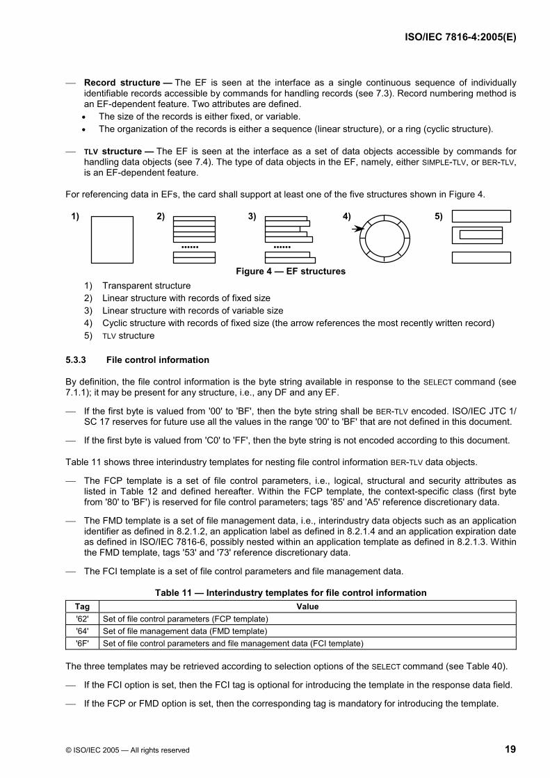
For referencing data in EFs, the card shall support at least one of the five structures shown in Figure 4.
2) 3) 4) 1)
•••••• ••••••
5)
Figure 4 — EF structures
1) Transparent structure 2) Linear structure with records of fixed size 3) Linear structure with records of variable size 4) Cyclic structure with records of fixed size (the arrow references the most recently written record) 5) TLV structure
5.3.3 File control information
By definition, the file control information is the byte string available in response to the SELECT command (see 7.1.1); it may be present for any structure, i.e., any DF and any EF.
If the first byte is valued from '00' to 'BF', then the byte string shall be BER-TLV encoded. ISO/IEC JTC 1/ SC 17 reserves for future use all the values in the range '00' to 'BF' that are not defined in this document.
If the first byte is valued from 'C0' to 'FF', then the byte string is not encoded according to this document.
Table 11 shows three interindustry templates for nesting file control information BER-TLV data objects.
The FCP template is a set of file control parameters, i.e., logical, structural and security attributes as listed in Table 12 and defined hereafter. Within the FCP template, the context-specific class (first byte from '80' to 'BF') is reserved for file control parameters; tags '85' and 'A5' reference discretionary data.
The FMD template is a set of file management data, i.e., interindustry data objects such as an application identifier as defined in 8.2.1.2, an application label as defined in 8.2.1.4 and an application expiration date as defined in ISO/IEC 7816-6, possibly nested within an application template as defined in 8.2.1.3. Within the FMD template, tags '53' and '73' reference discretionary data.
The FCI template is a set of file control parameters and file management data.
Table 11 — Interindustry templates for file control information Tag Value '62' Set of file control parameters (FCP template) '64' Set of file management data (FMD template) '6F' Set of file control parameters and file management data (FCI template)
The three templates may be retrieved according to selection options of the SELECT command (see Table 40).
If the FCI option is set, then the FCI tag is optional for introducing the template in the response data field.
If the FCP or FMD option is set, then the corresponding tag is mandatory for introducing the template.

ISO/IEC 7816-4:2005(E)
20 © ISO/IEC 2005 — All rights reserved
Table 12 lists the file control parameters, all in the context-specific class. When a control parameter is present for a file, the Table says whether it occurs only once (explicit indication), or it may be repeated (no indication).
Table 12 — File control parameter data objects Tag Length Value Applies to '80' Var. Number of data bytes in the file, excluding structural information Any EF, Once '81' 2 Number of data bytes in the file, including structural information if any Any file, Once '82' 1 File descriptor byte (see 5.3.3.3 and Table 14)
2 File descriptor byte and data coding byte (see Table 87) Any file
3 or 4 File descriptor byte, data coding byte and maximum record size on one or two bytes 5 or 6 File descriptor byte, data coding byte, maximum record size on two bytes and
number of records on one or two bytes
Any EF supporting
records '83' 2 File identifier Any file '84' up to 16 DF name Any DF '85' Var. Proprietary information not encoded in BER-TLV Any file '86' Var. Security attribute in proprietary format Any file '87' 2 Identifier of an EF containing an extension of the file control information Any DF, Once '88' 0 or 1 Short EF identifier (see 5.3.3.1) Any EF, Once '8A' 1 Life cycle status byte (LCS byte, see 5.3.3.2 and Table 13) Any file, Once '8B' Var. Security attribute referencing the expanded format (see 5.4.3.3 and Table 25) Any file, Once '8C' Var. Security attribute in compact format (see 5.4.3.1) Any file, Once '8D' 2 Identifier of an EF containing security environment templates (see 6.3.4) Any DF '8E' 1 Channel security attribute (see 5.4.3 and Table 15) Any file, Once 'A0' Var. Security attribute template for data objects (see 5.4.3) Any file, Once 'A1' Var. Security attribute template in proprietary format Any file 'A2' Var. Template consisting of one or more pairs of data objects:
Short EF identifier (tag '88') - File reference (tag '51', L > 2, see 5.3.1.2) Any DF
'A5' Var. Proprietary information encoded in BER-TLV Any file 'AB' Var. Security attribute template in expanded format (see 5.4.3.2) Any file, Once 'AC' Var. Cryptographic mechanism identifier template (see 5.4.2) Any DF In this context, ISO/IEC JTC 1/SC 17 reserves any other data object of the context-specific class (first byte from '80' to 'BF').
Part of the control information of a DF may additionally be present in an EF under the control of an application and referenced by tag '87' in the file control parameters. If present within such an EF, file control information shall be introduced by the appropriate tag, either a FCP tag, or a FCI tag.
5.3.3.1 Short EF identifier
The following rules apply for the use of tag '88' in the control parameters of any EF.
If the card supports selection by short EF identifiers (see 5.3.1.1) and if tag '88' is absent, then in the second byte of the file identifier (tag '83'), bits 5 to 1 encode the short EF identifier.
If tag '88' is present with a length set to zero, then the EF supports no short identifier.
If tag '88' is present with a length set to one and if bits 8 to 4 of the data element are not all equal and if bits 3 to 1 are set to 000, then bits 8 to 4 encode the short EF identifier (a number from one to thirty).
5.3.3.2 Life cycle status byte
The card, files and other objects, each have a life cycle; the life cycle status allows the card and the interface device to identify the different logical security states of the use of the card, files and other objects in the card. To support flexible management of the life cycle as an attribute (see ISO/IEC 7816-9[4]), this clause defines four primary states of the life cycle in the following order.
1) Creation state
2) Initialisation state
ISO/IEC 7816-4:2005(E)
© ISO/IEC 2005 — All rights reserved 21
3) Operational state
4) Termination state
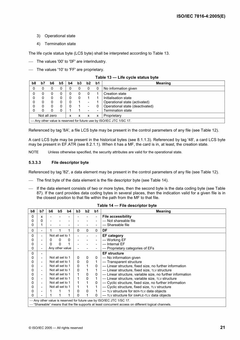
The life cycle status byte (LCS byte) shall be interpreted according to Table 13.
The values '00' to '0F' are interindustry.
The values '10' to 'FF' are proprietary.
Table 13 — Life cycle status byte b8 b7 b6 b5 b4 b3 b2 b1 Meaning 0 0 0 0 0 0 0 0 No information given 0 0 0 0 0 0 0 1 Creation state 0 0 0 0 0 0 1 1 Initialisation state 0 0 0 0 0 1 - 1 Operational state (activated) 0 0 0 0 0 1 - 0 Operational state (deactivated) 0 0 0 0 1 1 - - Termination state
Not all zero x x x x Proprietary Any other value is reserved for future use by ISO/IEC JTC 1/SC 17.
Referenced by tag '8A', a file LCS byte may be present in the control parameters of any file (see Table 12).
A card LCS byte may be present in the historical bytes (see 8.1.1.3). Referenced by tag '48', a card LCS byte may be present in EF.ATR (see 8.2.1.1). When it has a MF, the card is in, at least, the creation state.
NOTE Unless otherwise specified, the security attributes are valid for the operational state.
5.3.3.3 File descriptor byte
Referenced by tag '82', a data element may be present in the control parameters of any file (see Table 12).
The first byte of the data element is the file descriptor byte (see Table 14).
If the data element consists of two or more bytes, then the second byte is the data coding byte (see Table 87). If the card provides data coding bytes in several places, then the indication valid for a given file is in the closest position to that file within the path from the MF to that file.
Table 14 — File descriptor byte b8 b7 b6 b5 b4 b3 b2 b1 Meaning 0 x - - - - - - File accessibility 0 0 - - - - - - — Not shareable file 0 1 - - - - - - — Shareable file 0 - 1 1 1 0 0 0 DF 0 - Not all set to 1 - - - EF category 0 - 0 0 0 - - - — Working EF 0 - 0 0 1 - - - — Internal EF 0 - Any other value - - - — Proprietary categories of EFs 0 - EF structure 0 - Not all set to 1 0 0 0 — No information given 0 - Not all set to 1 0 0 1 — Transparent structure 0 - Not all set to 1 0 1 0 — Linear structure, fixed size, no further information 0 - Not all set to 1 0 1 1 — Linear structure, fixed size, TLV structure 0 - Not all set to 1 1 0 0 — Linear structure, variable size, no further information 0 - Not all set to 1 1 0 1 — Linear structure, variable size, TLV structure 0 - Not all set to 1 1 1 0 — Cyclic structure, fixed size, no further information 0 - Not all set to 1 1 1 1 — Cyclic structure, fixed size, TLV structure 0 - 1 1 1 0 0 1 — TLV structure for BER-TLV data objects 0 - 1 1 1 0 1 0 — TLV structure for SIMPLE-TLV data objects
Any other value is reserved for future use by ISO/IEC JTC 1/SC 17. “Shareable” means that the file supports at least concurrent access on different logical channels.

ISO/IEC 7816-4:2005(E)
22 © ISO/IEC 2005 — All rights reserved
5.4 Security architecture
5.4.1 General
This clause describes security status, security attributes and security mechanisms.
Security status The security status represents the current state possibly achieved after completion of the answer to reset and a possible protocol and parameter selection and / or a single command or a sequence of commands possibly performing authentication procedures. The security status may also result from completion of a security procedure related to the identification of the involved entities, if any, e.g., by proving knowledge of a password (e.g., using a VERIFY command) or knowledge of a key (e.g., using a GET CHALLENGE command followed by an EXTERNAL AUTHENTICATE command, or using a sequence of GENERAL AUTHENTICATE commands), or by secure messaging (e.g., message authentication). Four security statuses are considered. Global security status — In a card using a hierarchy of DFs, it may be modified by completion of an MF-
related authentication procedure (e.g., entity authentication by a password or a key attached to the MF). Application-specific security status — It may be modified by completion of an application-related
authentication procedure (e.g., entity authentication by a password or a key attached to the application); it may be maintained, recovered or lost by application selection; this modification may be relevant only for the application to which the authentication procedure belongs. If logical channels apply, then the application-specific security status may depend on the logical channel.
File-specific security status — It may be modified by completion of a DF-related authentication procedure (e.g., entity authentication by a password or by a key attached to the specific DF); it may be maintained, recovered or lost by file selection; this modification may be relevant only for the application to which the authentication procedure belongs. If logical channels apply, then the file-specific security status may depend on the logical channel.
Command-specific security status — It only exists while processing a command using secure messaging and involving authentication; such a command may leave the other security status unchanged.
Security attributes The security attributes, when they exist, define which actions are allowed, and under which conditions. The security attributes of a file depend on its category (DF or EF) and on optional parame-ters in its file control information and / or in that of its parent file(s). Security attributes may also be associated with commands, data objects and tables & views. In particular, security attributes may specify the security status of the card to be in force before accessing data; restrict access to data to certain functions (e.g., read only) if the card has a particular status; define which security functions shall be performed to obtain a specific security status.
Security mechanisms This clause considers the following security mechanisms. Entity authentication with password — The card compares data received from the outside world with
secret internal data. This mechanism may be used for protecting the rights of the user. Entity authentication with key — The entity to authenticate has to prove the knowledge of the relevant
secret or private key in an authentication procedure (e.g., a GET CHALLENGE command followed by an EXTERNAL AUTHENTICATE command, a sequence of GENERAL AUTHENTICATE commands).
Data authentication — Using internal data, either a secret key or a public key, the card checks redun-dant data received from the outside world. Alternately, using secret internal data, either a secret key or a private key, the card computes a data element (cryptographic checksum or digital signature) and inserts it in the data sent to the outside world. This mechanism may be used for protecting the rights of a provider.
Data encipherment — Using secret internal data, either a secret key or a private key, the card deciphers a cryptogram received in a data field. Alternately, using internal data, either a secret key or a public key, the card computes a cryptogram and inserts it in a data field, possibly together with other data. This mechanism may be used to provide a confidentiality service, e.g., key management and conditional access. In addition to the cryptogram mechanism, data confidentiality can be achieved by data conceal-ment. In this case, the card computes a string of concealing bytes and adds it by exclusive-or to bytes received from or sent to the outside world. This mechanism may be used for protecting privacy and for reducing possibilities of message filtering.
The result of an authentication may be logged in an internal EF according to application requirements.

ISO/IEC 7816-4:2005(E)
© ISO/IEC 2005 — All rights reserved 23
5.4.2 Cryptographic mechanism identifier template
Referenced by tag 'AC', one or more cryptographic mechanism identifier templates may be present in the control parameters of any DF (see Table 12). Each one explicitly indicates the meaning of a cryptographic mechanism reference in the DF and its hierarchy. Such a template shall consist of two or more data objects.
The first data object shall be a cryptographic mechanism reference, tag '80' (see Table 33).
The second data object shall be an object identifier, tag '06', as defined in ISO/IEC 8825-1. The identified object shall be a cryptographic mechanism specified or registered within a standard, e.g., an ISO standard. Examples of cryptographic mechanisms are encryption algorithms (e.g., ISO/IEC 18033[18]), message authentication codes (e.g., ISO/IEC 9797[7]), authentication protocols (e.g., ISO/IEC 9798[8]), digital signatures (e.g., ISO/IEC 9796[6] or 14888[16]), registered cryptographic algorithms (e.g., ISO/IEC 9979[9]), and so on.
If present, one or more subsequent data objects shall either identify a mechanism, tag '06', used by the previous mechanism (i.e., a mode of operation, e.g., ISO/IEC 10116[11], or a hash-function, e.g., ISO/IEC 10118[12]), or indicate parameters (tag dependent on the previous mechanism).
EXAMPLES (see explanations in annex A)
{'AC' - '0B' - {'80'-'01'-'01'} - {'06'-'06'-'28818C710201'}} The template associates the local reference '01' to the first encryption algorithm in ISO/IEC 18033-2[18].
{'AC' - '11' - {'80'-'01'-'02'} - {'06'-'05'-'28CC460502'} - {'06'-'05'-'28CF060303'}} The first object identifier refers to the second authentication mechanism in ISO/IEC 9798-5[8]. The second object identifier refers to the third dedicated hash-function in ISO/IEC 10118-3[12]. Therefore the template associates the local reference '02' to GQ2 using SHA-1.
5.4.3 Security attributes
Referenced by tags '86', '8B', '8C', '8E', 'A0', 'A1', 'AB', security attributes may be present in the control pa-rameters of any file (see Table 12). Any object in the card (e.g., command, file, data object, table & view) may be associated with more than one security attribute and / or with a reference contained in a security attribute.
Referenced by tag 'A0', a security attribute template for data objects may be present in the control parameters of any file. Such a template is the concatenation of a security attribute data object (tags '86', '8B', '8C', '8E', 'A0', 'A1', 'AB') and a tag list data object (tag '5C', see 8.5.1) indicating the relevant data objects in the file.
Referenced by tag '8E', a channel security attribute (at most one) may be present in the control parameters of any file (see Table 12) and in any appropriate security environment (SE, see 6.3.3). It shall be interpreted according to Table 15.
"Not shareable" means that at most one logical channel shall be available. The physical technology of the channel may be limited.
"Secured" means that SM keys (see 6) shall be available (e.g., established by a previous authentication).
"User authenticated" means that the user shall be authenticated (e.g., a successful password verification).
Table 15 — Channel security attribute b8 b7 b6 b5 b4 b3 b2 b1 Meaning 0 0 0 0 0 - - 1 Not shareable 0 0 0 0 0 - 1 - Secured 0 0 0 0 0 1 - - User authenticated
Any other value is reserved for future use by ISO/IEC JTC 1/SC 17. In SCQL environment (see ISO/IEC 7816-7[4], commands for structured card query language), security attributes can be specified in SCQL operations, e.g., CREATE TABLE and CREATE VIEW commands. If security attributes based on this clause are used, then they shall be conveyed in a data object with tags '8B', '8C' or 'AB' in the security attribute parameters of an SCQL operation.
Formats This clause defines two formats for binding objects and security attributes: a compact format based on bitmaps and an expanded format that extends the compact format by TLV list management.

ISO/IEC 7816-4:2005(E)
24 © ISO/IEC 2005 — All rights reserved
5.4.3.1 Compact format
In compact format, an access rule consists of an access mode byte followed by one or more security condition bytes. Access control to an object is managed by binding access rules to the related object. If several access rules are present in the value field of a data object with tag '8C' (see Table 12), they represent an OR condition.
Access mode bytes Each bit 7 to 1 indicates either the absence of security condition byte when set to 0, or the presence of a security condition byte in the same order (bits 7 to 1) when set to 1. When bit 8 is set to 1, bits 7 to 4 may be used for additional commands, e.g., application-specific commands.
Tables 16 to 19 define access mode bytes respectively for DFs, EFs, data objects and tables & views.
Table 16 — Access mode byte for DFs b8 b7 b6 b5 b4 b3 b2 b1 Meaning 0 - - - - - - - Bits 7 to 1 according to this table 1 - - - - - - - Bits 3 to 1 according to this table (bits 7 to 4 proprietary) 0 1 - - - - - - DELETE FILE (self) 0 - 1 - - - - - TERMINATE CARD USAGE (MF), TERMINATE DF 0 - - 1 - - - - ACTIVATE FILE 0 - - - 1 - - - DEACTIVATE FILE - - - - - 1 - - CREATE FILE (DF creation) - - - - - - 1 - CREATE FILE (EF creation) - - - - - - - 1 DELETE FILE (child)
Table 17 — Access mode byte for EFs b8 b7 b6 b5 b4 b3 b2 b1 Meaning 0 - - - - - - - Bits 7 to 1 according to this table 1 - - - - - - - Bits 3 to 1 according to this table (bits 7 to 4 proprietary) 0 1 - - - - - - DELETE FILE 0 - 1 - - - - - TERMINATE EF 0 - - 1 - - - - ACTIVATE FILE 0 - - - 1 - - - DEACTIVATE FILE - - - - - 1 - - WRITE BINARY, WRITE RECORD, APPEND RECORD - - - - - - 1 - UPDATE BINARY, UPDATE RECORD, ERASE BINARY, ERASE RECORD (S) - - - - - - - 1 READ BINARY, READ RECORD (S), SEARCH BINARY, SEARCH RECORD
Table 18 — Access mode byte for data objects b8 b7 b6 b5 b4 b3 b2 b1 Meaning 0 - - - - - - - Bits 7 to 1 according to this table 1 - - - - - - - Bits 3 to 1 according to this table (bits 7 to 4 proprietary) 0 x x x x - - - 000 (any other value is reserved for future use) - - - - - 1 - - MANAGE SECURITY ENVIRONMENT - - - - - - 1 - PUT DATA - - - - - - - 1 GET DATA
Table 19 — Access mode byte for tables & views b8 b7 b6 b5 b4 b3 b2 b1 Meaning 0 - - - - - - - Bits 7 to 1 according to this table 1 - - - - - - - Bits 3 to 1 according to this table (bits 7 to 4 proprietary) 0 1 - - - - - - CREATE USER, DELETE USER 0 - 1 - - - - - GRANT, REVOKE 0 - - 1 - - - - CREATE TABLE, CREATE VIEW, CREATE DICTIONARY 0 - - - 1 - - - DROP TABLE, DROP VIEW - - - - - 1 - - INSERT - - - - - - 1 - UPDATE, DELETE - - - - - - - 1 FETCH
Security condition byte Each security condition byte specifies which security mechanisms are necessary to conform to the access rule. Table 20 shows the security condition byte.

ISO/IEC 7816-4:2005(E)
© ISO/IEC 2005 — All rights reserved 25
Table 20 — Security condition byte b8 b7 b6 b5 b4 b3 b2 b1 Meaning 0 0 0 0 0 0 0 0 No condition 1 1 1 1 1 1 1 1 Never - - - - 0 0 0 0 No reference to a security environment - - - - Not all equal Security environment identifier (SEID byte, see 6.3.4) from one to fourteen- - - - 1 1 1 1 Reserved for future use 0 - - - - - - - At least one condition 1 - - - - - - - All conditions - 1 - - - - - - Secure messaging - - 1 - - - - - External authentication - - - 1 - - - - User authentication (e.g., password)
Bits 8 to 5 indicate the required security conditions. If not all equal, bits 4 to 1 identify a security environment (see 6.3.4, SEID byte from one to fourteen) and the mechanisms defined in the security environment shall be used according to the indications in bits 7 to 5 for command protection and / or external authentication and / or user authentication. If bit 8 is set to 1, then all the conditions set in bits 7 to 5 shall be satisfied. If bit 8 is set to 0, then at least one of the conditions set in bits 7 to 5 shall be satisfied. If bit 7 is set to 1, then the control reference template (see 6.3.1) of the security environment identified in
bits 4 to 1, i.e., a SEID byte from one to fourteen, describes whether secure messaging shall apply to the command data field and / or to the response data field (see usage qualifier byte, Table 35).
5.4.3.2 Expanded format
In expanded format, an access rule consists of an access mode data object followed by one or more security condition data objects. Access control to an object is managed by referencing access rules from the related object. A template with tag 'AB' may be present in the control parameters of any file (see Table 12) for such access rules.
Access mode data objects An access mode data object contains either an access mode byte (see Tables 16 to 19), or a list of command descriptions or a proprietary state machine description; subsequent security condition data objects are relevant for all the indicated commands. Table 21 shows access mode data objects.
Table 21 — Access mode data objects Tag Length Value Meaning '80' 1 Access mode byte See Tables 16 to 19
'81' to '8F' Var. Command header description List of [part of] command headers (see Table 22) '9C' Var. Proprietary state machine description
If the tag is from '81' to '8F', then the access mode data element represents a list of possible combinations of values of the four bytes CLA, INS, P1 and P2 in the command header. Depending on bits 4 to 1 of the tag, the list contains only values as described in Table 22. Several groups may appear in order to define a set of commands, e.g., values of INS P1 P2, INS P1 P2, … for tag '87'.
Table 22 — Tags '81' to '8F' for access mode data objects b8 b7 b6 b5 b4 b3 b2 b1 Meaning 1 0 0 0 x x x x The command description includes 1 0 0 0 1 - - - — (CLA), i.e., the value of CLA 1 0 0 0 - 1 - - — (INS), i.e., the value of INS 1 0 0 0 - - 1 - — (P1), i.e., the value of P1 1 0 0 0 - - - 1 — (P2), i.e., the value of P2
The value of CLA shall encode zero as channel number with the meaning that the description is independent from logical channels. The INS code shall be even with the meaning that the description is independent from data field format indications.
Security condition data objects According to Table 23, the security condition data objects define the security actions required for accessing an object protected through the particular access mode data object. If used as a security condition, a control reference template (see 6.3.1) referenced by tag 'A4' (AT), 'B4' (CCT), 'B6' (DST) or 'B8' (CT) shall contain a usage qualifier data object (see Table 35) indicating the security action.

ISO/IEC 7816-4:2005(E)
26 © ISO/IEC 2005 — All rights reserved
Table 23 — Security condition data objects Tag Length Value Meaning '90' 0 - Always
'97' 0 - Never
'9E' 1 Security condition byte See Table 20
'A4' Var. Control reference template External or user authentication depending on the usage qualifier
'B4', 'B6', 'B8' Var. Control reference template SM in command and / or response depending on the usage qualifier
'A0' Var. Security condition data objects At least one security condition shall be fulfilled (OR template)
'A7' Var. Security condition data objects Inversion of the security conditions (NOT template)
'AF' Var. Security condition data objects Every security condition shall be fulfilled (AND template)
Several security condition data objects may be attached to the same operation.
If security condition data objects are nested in an OR template (tag 'A0'), then at least one security condition shall be fulfilled before acting.
If security condition data objects are not nested in an OR template (tag 'A0') or if they are nested in an AND template (tag 'AF'), then every security condition shall be fulfilled before acting.
If security condition data objects are nested in a NOT template (tag 'A7'), then the security conditions are true until they are not fulfilled.
5.4.3.3 Access rule references
Access rules in expanded format may be stored in an EF supporting a linear structure with records of variable size. Such an EF is named EF.ARR. One or more access rules may be stored in each record referenced by a record number. Such a record number is named ARR byte. Table 24 illustrates the layout of an EF.ARR.
Table 24 — EF.ARR layout Record number (ARR byte) Record content (one or more access rules)
1 Access mode data object, one or more security condition data objects, access mode data object, …
2 Access mode data object, one or more security condition data objects, …
Referenced by tag '8B', security attribute data objects referencing expanded format (see Table 25) may be present in the control parameters of any file (see Table 12).
If the length is one, then the value field is an ARR byte that references a record in an implicitly known EF.ARR.
If the length is three, then the value field is a file identifier followed by an ARR byte; the file identifier references EF.ARR and the ARR byte is the record number in EF.ARR.
If the length is even and at least four, then the value field is a file identifier followed by one or more pairs of bytes. Each pair consists of a SEID byte followed by an ARR byte; the SEID byte identifies the security environment where the access rules referenced by the ARR byte apply.
Table 25 — Security attribute data objects referencing expanded format Tag Length Value '8B' 1 ARR byte (one byte)
3 File identifier (two bytes) - ARR byte (one byte) Even, > 3 File identifier (two bytes) - SEID byte (one byte) - ARR byte (one byte) - [SEID byte - ARR byte] - …
The ARR byte of the current SE indicates the access rules valid for the current access to the application DF. NOTE If no SE is set in a former MANAGE SECURITY ENVIRONMENT command, then the default SE is the current SE.
5.4.4 Security support data elements
This clause specifies a collection of security support data elements with rules governing the way their values are handled. The security support data elements extend and refine the control reference data objects. The card may provide them as generic support to security mechanisms performed by an application. Applications

ISO/IEC 7816-4:2005(E)
© ISO/IEC 2005 — All rights reserved 27
may reference them for secure messaging and for security operations (see ISO/IEC 7816-8[4]). This clause specifies neither some characteristics of the security support data elements, e.g., their lengths, nor the algorithms that alter their value.
Principles The card shall maintain and use the value of security support data elements as follows. Update is done with new values either computed by the card, or provided by the outside world, in
accordance with the specific rule for a specific type of security support data element. Update is performed before any output is produced for the command causing an update. The update is
independent of the completion status of the command. If the value is to be used by the application in an operation that causes an update, the update is performed before the value is used.
Access to application-specific security support data elements is restricted to functions performed by the specific application.
NOTE The actual security achieved in a command-response pair ultimately depends on the algorithms and protocols specified by the application; the card only provides support with these data elements and associated usage rules.
Data elements The card may support command-response pair security with data elements called progres-sion values. Increased at specific events throughout the life of the card, these values are different each time the card is activated. Two progression values are specified: a card session counter and a session identifier. The card session counter is incremented once during card activation. The session identifier is computed from the card session counter and from data provided by the outside
world.
Two types of progression values are specified. Internal progression values, if so specified for an application, register the number of times specific events
are performed. The data element shall be incremented after the event; the card may provide a reset function for these counters which if so specified for an application sets its value to zero. Internal progression values cannot be controlled by the outside world and are suitable for use as secured in-card approximate representations of real time. Their values can be used in cryptographic computations.
External progression values, if so specified for an application, shall only be updated by a data value from the outside world. The new value shall be numerically larger than the current value stored in the card.
References The card may provide access to the value of security support data elements as follows. An EF may be present in the MF, e.g., for a card session counter, or in an application DF, e.g., for
application-specific progression values. Auxiliary data objects (tags '88', '92', '93', see Table 33) may be present in a control reference template.
These tags can be used if the SE supports unambiguous use of these data elements. Within the interindustry template referenced by tag '7A', the context-specific class (first byte from '80' to
'BF') is reserved for security support data objects as listed in Table 26.
Table 26 — Security support data objects Tag Value '7A' Set of security support data objects with the following tags
'80' Card session counter '81' Card session identifier '82' to '8E' File selection counter '93' Digital signature counter '9F2X' Internal progression value ('X' is a specific index, e.g., an index referencing a counter of file selections) '9F3Y' External progression value ('Y' is a specific index, e.g., an index referencing an external time stamp) In this context, ISO/IEC JTC 1/SC 17 reserves any other data object of the context-specific class (first byte from '80' to 'BF').

ISO/IEC 7816-4:2005(E)
28 © ISO/IEC 2005 — All rights reserved
6 Secure messaging
Secure messaging (SM) protects all or part of a command-response pair, or a concatenation of consecutive data fields (command chaining, see 5.1.1.1; use of SW1 set to '61'), by ensuring two basic security functions: data confidentiality and data authentication. Secure messaging is achieved by applying one or more security mechanisms. Possibly explicitly identified by a cryptographic mechanism identifier template (see 5.4.2) in the control parameters of any DF (see 5.3.3), each security mechanism involves a cryptographic algorithm, a mode of operation, a key, an argument (input data) and often, initial data.
The transmission and reception of data fields may be interleaved with the processing of security mechanisms. This specification does not preclude the determination by sequential analysis of which mechanisms and which security items shall be used for processing the remaining part of the data field.
Two or more security mechanisms may use the same cryptographic algorithm with different modes of operation. The hereafter specified padding rules do not preclude such a feature.
6.1 SM fields and SM data objects
By definition, any command or response data field in SM format, as also the SM template (tag '7D'), is an SM field. Each SM field shall be encoded in BER-TLV (see 5.2.2) where the context-specific class (first byte from '80' to 'BF') is reserved for SM data objects. In command-response pairs, the SM format may be selected either implicitly, i.e., known before issuing the command, or explicitly, i.e., indicated by CLA (see 5.1.1).
NOTE Command chaining and / or the use of SW1 set to '61' induces sequences of commands where data fields (and consequently, data objects) may be split in smaller consecutive data fields. In such a case, when using SM format, the concatenation of all the consecutive data fields in the same direction in the same sequence is an SM field.
Table 27 shows the SM data objects specified in this document, all in the context-specific class. Some SM data objects (SM tags '82', '83', 'B0', 'B1') are recursive, i.e., the plain value field is an SM field.
Table 27 — SM data objects Tag Value
'80', '81' Plain value not encoded in BER-TLV '82', '83' Cryptogram (plain value encoded in BER-TLV and including SM data objects, i.e., an SM field) '84', '85' Cryptogram (plain value encoded in BER-TLV, but not including SM data objects) '86', '87' Padding-content indicator byte followed by cryptogram (plain value not encoded in BER-TLV)
'89' Command header (CLA INS P1 P2, four bytes) '8E' Cryptographic checksum (at least four bytes)
'90', '91' Hash-code '92', '93' Certificate (data not encoded in BER-TLV) '94', '95' Security environment identifier (SEID byte) '96', '97' One or two bytes encoding Ne in the unsecured command-response pair (possibly empty)
'99' Processing status (SW1-SW2, two bytes; possibly empty) '9A', '9B' Input data element for the computation of a digital signature (the value field is signed) '9C', '9D' Public key
'9E' Digital signature 'A0', 'A1' Input template for the computation of a hash-code (the template is hashed)
'A2' Input template for the verification of a cryptographic checksum (the template is included) 'A4', 'A5' Control reference template for authentication (AT) 'A6', 'A7' Control reference template for key agreement (KAT)
'A8' Input template for the verification of a digital signature (the template is signed) 'AA', 'AB' Control reference template for hash-code (HT) 'AC', 'AD' Input template for the computation of a digital signature (the concatenated value fields are signed) 'AE', 'AF' Input template for the verification of a certificate (the concatenated value fields are certified) 'B0', 'B1' Plain value encoded in BER-TLV and including SM data objects, i.e., an SM field 'B2', 'B3' Plain value encoded in BER-TLV, but not including SM data objects 'B4', 'B5' Control reference template for cryptographic checksum (CCT) 'B6', 'B7' Control reference template for digital signature (DST) 'B8', 'B9' Control reference template for confidentiality (CT) 'BA', 'BB' Response descriptor template 'BC', 'BD' Input template for the computation of a digital signature (the template is signed)
'BE' Input template for the verification of a certificate (the template is certified) In this context, ISO/IEC JTC 1/SC 17 reserves any other data object of the context-specific class (first byte from '80' to 'BF').

ISO/IEC 7816-4:2005(E)
© ISO/IEC 2005 — All rights reserved 29
In each SM field, bit 1 of the last byte of the tag field (tag parity) of each SM data object (context-specific class) indicates whether the SM data object shall be included (bit 1 set to 1, odd tag number) or not (bit 1 set to 0, even tag number) in the computation of a data element for authentication (cryptographic checksum, see 6.2.3.1, or digital signature, see 6.2.3.2). If present, the data objects of the other classes (e.g., interindustry data objects) shall be included in the computation. If such a computation occurs, the data element shall be the value field of a SM data object for authentication (SM tags '8E', '9E') at the end of the SM field.
There are two categories of SM data objects.
Each basic SM data object (see 6.2) conveys a plain value, or an input or result of a security mechanism.
Each auxiliary SM data object (see 6.3) conveys a control reference template, or a security environment identifier, or a response descriptor template.
NOTE Basic SM data objects are also used to control security operations (see ISO/IEC 7816-8[4]). Auxiliary SM data objects are also used to manage security environment (see 7.5.11). The global approach to security by secure messaging shares several security-related issues with the security operations, i.e., the atomic approach to security. Annex B illustrates the synergy between the two approaches.
6.2 Basic SM data objects
6.2.1 SM data objects for encapsulating plain values
Encapsulation is mandatory for SM fields and for data not encoded in BER-TLV. It is optional for BER-TLV, not including SM, data objects. Table 28 shows SM data objects for encapsulating plain values.
Table 28 — SM data objects for encapsulating plain values Tag Value
'B0', 'B1' Plain value encoded in BER-TLV and including SM data objects (i.e., an SM field) 'B2', 'B3' Plain value encoded in BER-TLV, but not including SM data objects '80', '81' Plain value not encoded in BER-TLV
'89' Command header (CLA INS P1 P2, four bytes) '96', '97' One or two bytes encoding Ne in the unsecured command-response pair (possibly empty)
'99' Processing status (SW1-SW2, two bytes; possibly empty)
6.2.2 SM data objects for confidentiality
Table 29 shows SM data objects for confidentiality.
Table 29 — SM data objects for confidentiality Tag Value
'82', '83' Cryptogram (plain value encoded in BER-TLV and including SM data objects, i.e., an SM field) '84', '85' Cryptogram (plain value encoded in BER-TLV, but not including SM data objects) '86', '87' Padding-content indicator byte (see Table 30) followed by cryptogram (plain value not encoded in BER-TLV)
A security mechanism for confidentiality consists of an appropriate cryptographic algorithm in an appropriate mode of operation. In the absence of explicit indication and when no mechanism is implicitly selected for confidentiality, a default mechanism shall apply.
For computing a cryptogram to be preceded by a padding indication, the default mechanism is a block cipher in “electronic code book” mode, which may involve padding. Padding for confidentiality may have an influence on transmission: the cryptogram (one or more blocks) may be longer than the plain value.
For computing a cryptogram not to be preceded by a padding indication, the default mechanism is a stream cipher. In this case, the cryptogram is the exclusive-or of the string of data bytes to conceal with a concealing string of the same length. Concealment thus requires no padding and the string of data bytes is recovered by the same operation.
Padding and / or content shall be indicated when the plain value is not encoded in BER-TLV. If padding applies but is not indicated, the rules specified in 6.2.3.1 apply. Table 30 shows the padding-content indicator byte.

ISO/IEC 7816-4:2005(E)
30 © ISO/IEC 2005 — All rights reserved
Table 30 — Padding-content indicator byte Value Meaning
'00' No further indication '01' Padding as specified in 6.2.3.1 '02' No padding '1X' One to four secret keys for enciphering information, not keys ('X' is a bitmap with any value from '0' to 'F')
'11' indicates the first key (e.g., an “even” control word in a pay TV system) '12' indicates the second key (e.g., an “odd” control word in a pay TV system) '13' indicates the first key followed by the second key (e.g., a pair of control words in a pay TV system)
'2X' Secret key for enciphering keys, not information ('X' is a reference with any value from '0' to 'F') (e.g., in a pay TV system, either an operational key for enciphering control words, or a management key for enciphering operational keys)
'3X' Private key of an asymmetric key pair ('X' is a reference with any value from '0' to 'F') '4X' Password ('X' is a reference with any value from '0' to 'F')
'80' to '8E' Proprietary Any other value is reserved for future use by ISO/IEC JTC 1/SC 17.
6.2.3 SM data objects for authentication
Table 31 shows SM data objects for authentication.
Table 31 — SM data objects for authentication Tag Value '8E' Cryptographic checksum (at least four bytes)
'90', '91' Hash-code '92', '93' Certificate (data not encoded in BER-TLV) '9C', '9D' Public key
'9E' Digital signature Input data objects (see also ISO/IEC 7816-8[4])
'9A', '9B' Input data element for the computation of a digital signature (the value field is signed) 'A0', 'A1' Input template for the computation of a hash-code (the template is hashed)
'A2' Input template for the verification of a cryptographic checksum (the template is included) 'A8' Input template for the verification of a digital signature (the template is signed)
'AC', 'AD' Input template for the computation of a digital signature (the concatenated value fields are signed) 'AE', 'AF' Input template for the verification of a certificate (the concatenated value fields are certified) 'BC', 'BD' Input template for the computation of a digital signature (the template is signed)
'BE' Input template for the verification of a certificate (the template is certified) 6.2.3.1 Cryptographic checksum data element
The computation of a cryptographic checksum involves an initial check block, a secret key and either a block cipher algorithm (see ISO/IEC 18033[18]), or a hash-function (see ISO/IEC 10118[12]).
The computation method may be part of the system specifications. Alternately, a cryptographic mechanism identifier template, see 5.4.2, may identify a standard (e.g., ISO/IEC 9797-1[7]) fixing a computation method.
Unless otherwise specified, the following computation method shall be used. Under the control of the key, the algorithm basically converts a current input block of k bytes (typically 8, 16 or 20) into a current output block of the same size. The computation is performed in the following consecutive stages.
Initial stage — The initial stage shall set either one of the following blocks as the initial check block: the null block, i.e., k bytes set to '00', the chaining block, i.e., a result from former computations, namely for a command, the final check block
of the previous command and for a response, the final check block of the previous response, the initial value block provided e.g., by the outside world, the auxiliary block resulting from converting auxiliary data under the control of the key. If the auxiliary data
is less than k bytes, then bits set to 0 head it up to the block size.

ISO/IEC 7816-4:2005(E)
© ISO/IEC 2005 — All rights reserved 31
Sequential stage(s) — The command header (CLA INS P1 P2) may be encapsulated for protection (SM tag '89'). However, if bits 8 to 6 of CLA are set to 000 and bits 4 and 3 to 11 (see 5.1.1), then the first data block consists of the command header (CLA INS P1 P2) followed by one byte set to '80' and k–5 bytes set to '00'.
The cryptographic checksum shall include any secure messaging data object having an odd tag number and any data object with the first byte not from '80' to 'BF'. Those data objects shall be included data block by data block in the current check block. The splitting into data blocks shall be performed as follows. The blocking shall be continuous at the border between adjacent data objects to include. The padding shall apply at the end of each data object to include followed either by a data object not to
include, or by no further data object. The padding consists of one mandatory byte set to '80' followed, if needed, by 0 to k–1 bytes set to '00', until the respective data block is filled up to k bytes. Padding for authentication has no influence on transmission as the padding bytes shall not be transmitted.
In this mechanism, the mode of operation is “cipher block chaining” (see ISO/IEC 10116[11]). The first input is the exclusive-or of the initial check block with the first data block. The first output results from the first input. The current input is the exclusive-or of the previous output with the current data block. The current output results from the current input.
Final stage — The final check block is the last output. The final stage extracts a cryptographic checksum (first m bytes, at least four) from the final check block.
6.2.3.2 Digital signature data element
The digital signature schemes rely on asymmetric cryptographic techniques (see ISO/IEC 9796[6], 14888[16]). The computation implies a hash-function (see ISO/IEC 10118[12]). The data input consists of the value field of a digital signature input data object, or of the concatenation of the value fields of data objects forming a digital signature input template. It may be determined by the mechanism specified in 6.2.3.1.
6.3 Auxiliary SM data objects
Table 32 shows auxiliary SM data objects. Table 32 — Auxiliary SM data objects
Tag Value '94', '95' Security environment identifier (SEID byte) 'A4', 'A5' Control reference template valid for authentication (AT) 'A6', 'A7' Control reference template valid for key agreement (KAT) 'AA', 'AB' Control reference template valid for hash-code (HT) 'B4', 'B5' Control reference template valid for cryptographic checksum (CCT) 'B6', 'B7' Control reference template valid for digital signature (DST) 'B8', 'B9' Control reference template valid for confidentiality (CT) 'BA', 'BB' Response descriptor template
6.3.1 Control reference templates
Six control reference templates are defined, valid for authentication (AT), key agreement (KAT), hash-code (HT), cryptographic checksum (CCT), digital signature (DST) and confidentiality (CT) using either symmetric or asymmetric cryptographic techniques (CT-sym and CT-asym).
Each security mechanism involves a cryptographic algorithm in a mode of operation and uses a key and, possibly, initial data. Such items are selected either implicitly, i.e., known before issuing the command, or explicitly, i.e., by control reference data objects nested in control reference templates. Within the control reference templates, the context-specific class (first byte from '80' to 'BF') is reserved for control reference data objects.
In a SM field, the last possible position of a control reference template is just before the first data object to which the referred mechanism applies. For example, the last possible position of a template valid for cryptographic checksum (CCT) is just before the first data object to include in the computation.
Each control reference remains valid until a new control reference is provided for the same mechanism. For example, a command may provide control references for the next command.

ISO/IEC 7816-4:2005(E)
32 © ISO/IEC 2005 — All rights reserved
6.3.2 Control reference data objects in control reference templates
Each control reference template (CRT) is a set of control reference data objects: a cryptographic mechanism reference, a file and key reference, an initial data reference, a usage qualifier and, only in a control reference template for confidentiality, a cryptogram content reference.
The cryptographic mechanism reference denotes a cryptographic algorithm in a mode of operation. The control parameters of any DF (see tag 'AC' in Table 12) may contain cryptographic mechanism identifier templates (see 5.4.2). Each one indicates the meaning of a cryptographic mechanism reference.
The file reference (same encoding as in 5.3.1.2) denotes the file where the key reference is valid. If no file reference is present, then the key reference is valid in the current DF, possibly an application DF. The key reference unambiguously identifies the key to use.
The initial data reference, when applied to cryptographic checksums, indicates the initial check block. If no initial data reference is present and no initial check block implicitly selected, then the null block applies. Moreover, before transmitting the first data object for confidentiality using a stream cipher, a template for confidentiality shall provide auxiliary data for initializing the computation of the string of concealing bytes.
Table 33 lists control reference data objects and indicates to which control reference template they are relevant. All the control reference data objects are in the context-specific class.
Table 33 — Control reference data objects in control reference templates Tag Value AT KAT HT CCT DST CT-asym CT-sym '80' Cryptographic mechanism reference x x x x x x x
File and key references '81' — File reference (same encoding as 5.3.1.2) x x x x x x x '82' — DF name (see 5.3.1.1) x x x x x x x '83' — Reference of a secret key (for direct use) x x x x x
— Reference of a public key x x x x x — Qualifier of reference data x
'84' — Reference for computing a session key x x x x — Reference of a private key x x x x
'A3' Key usage template (see text below) x x x x x x x Initial data reference: Initial check block
'85' — L=0, null block x x x '86' — L=0, chaining block x x x '87' — L=0, previous initial value block plus one
L=k, initial value block
x x x
x
Initial data reference: Auxiliary data elements (see also 5.4.3) '88' — L=0, previous exchanged challenge plus one
L>0, no further indication x x x x
'89' to '8D'
— L=0, index of a proprietary data element L>0, value of a proprietary data element
x x
x
'90' — L=0, hash-code provided by the card x x '91' — L=0, random number provided by the card
L>0, random number x x x
x x x
'92' — L=0, time stamp provided by the card L>0, time stamp
x x x
x x
'93' — L=0, previous digital signature counter plus one L>0, digital signature counter
x x x
x x
x x
'94' Challenge or data element for deriving a key x x x
'95' Usage qualifier byte (see text below) x x x x x x '8E' Cryptogram content reference (see text below) x x
In this context, ISO/IEC JTC 1/SC 17 reserves any other data object of the context-specific class (first byte from '80' to 'BF'). A CRT may contain interindustry data objects, e.g., certificate holder authorization (tag '5F4C', see 6.3.4) in AT, header list or extended header list (tags '5D' and '4D', see 8.5.1) in HT or DST.

ISO/IEC 7816-4:2005(E)
© ISO/IEC 2005 — All rights reserved 33
In any control reference template, a key usage template (tag 'A3') may associate a file and key reference with a key usage counter and / or a key retry counter (see Table 34).
Table 34 — Key usage data objects Tag Value 'A3' Set of key usage data objects with the following tags
'80' to '84' File and key references as specified in Table 33 '90' Key usage counter '91' Key retry counter In this context, ISO/IEC JTC 1/SC 17 reserves any other data object of the context-specific class (first byte from '80' to 'BF').
In any control reference template for authentication (AT), for key agreement (KAT), for cryptographic checksum (CCT), for confidentiality (CT) or for digital signature (DST), a usage qualifier byte (tag '95') may specify the usage of the template either as a security condition (see 5.4.3.2 and Table 23), or in compliance with the MANAGE SECURITY ENVIRONMENT command (see 7.5.11). Table 35 shows the usage qualifier byte.
Table 35 — Usage qualifier byte b8 b7 b6 b5 b4 b3 b2 b1 Meaning 1 - - - - - - - Verification (DST, CCT), Encipherment (CT), External authentication (AT),
Key agreement (KAT) - 1 - - - - - - Computation (DST, CCT), Decipherment (CT), Internal authentication (AT),
Key agreement (KAT) - - 1 - - - - - Secure messaging in response data fields (CCT, CT, DST) - - - 1 - - - - Secure messaging in command data fields (CCT, CT, DST) - - - - 1 - - - User authentication, password based (AT) - - - - - 1 - - User authentication, biometry based (AT) - - - - - - x x xxxx xx00 (any other value is reserved for future use)
In any control reference template for confidentiality (CT), a cryptogram content reference (tag '8E') may specify the content of the cryptogram. The first byte of the value field is mandatory; its name is the cryptogram descriptor byte. Table 36 shows the cryptogram descriptor byte.
Table 36 — Cryptogram descriptor byte Value Meaning
'00' No further indication '1X' One to four secret keys for enciphering information, not keys ('X' is a bitmap with any value from '0' to 'F')
'11' indicates the first key (e.g., an “even” control word in a pay TV system) '12' indicates the second key (e.g., an “odd” control word in a pay TV system) '13' indicates the first key followed by the second key (e.g., a pair of control words in a pay TV system)
'2X' Secret key for enciphering keys, not information ('X' is a reference with any value from '0' to 'F') (e.g., in a pay TV system, either an operational key for enciphering control words, or a management key for enciphering operational keys)
'3X' Private key of an asymmetric key pair ('X' is a reference with any value from '0' to 'F') '4X' Password ('X' is a reference with any value from '0' to 'F')
'80' to 'FF' Proprietary Any other value is reserved for future use by ISO/IEC JTC 1/SC 17.
6.3.3 Security environments
This clause specifies security environments (SE) for referencing cryptographic algorithms, modes of operation, protocols, procedures, keys and any additional data needed for secure messaging and for security operations (see ISO/IEC 7816-8[4]). A SE consists of data elements stored in the card or resulting from some computation, to be processed by the specified algorithms. A SE may contain a mechanism to initialise non-persistent data to be used in the environment, e.g., a session key. A SE may provide directions for handling computation results, e.g., storage in the card. An interindustry SE template (tag '7B') describes a SE.
SE identifier A SE identifier (SEID byte) may reference any security environment, e.g., for secure messag-ing and for storing and restoring by a MANAGE SECURITY ENVIRONMENT command (see 7.5.11). Unless otherwise specified by the application, the value '00' denotes an empty environment where no
secure messaging and no authentication are defined.

ISO/IEC 7816-4:2005(E)
34 © ISO/IEC 2005 — All rights reserved
The value 'FF' denotes that no operation can be performed in this environment. Unless otherwise specified by the application, the value '01' is reserved for the default SE, always
available. This clause does not specify the content of the default SE; it may be empty. The value 'EF' is reserved for future use.
Components Control reference templates (CRT) may describe various components of a SE. Any relative control reference (files, keys or data) specified with a mechanism in the environment definition shall be resolved with respect to the DF selected before using the mechanism. Absolute control references (e.g., absolute path) need not be resolved. Within an SE, components may have two aspects: one being valid for SM in command data fields and the other for SM in response data fields.
At any time during card operation, a current SE shall be active, either by default or as a result of commands performed by the card. The current SE contains one or more components among the following components. Some components belong to the default SE associated with the current DF. Some components are transmitted in commands using secure messaging. Some components are transmitted in MANAGE SECURITY ENVIRONMENT commands. Some components are invoked by a SEID byte in a MANAGE SECURITY ENVIRONMENT command.
The current SE is valid until there is a warm reset or a deactivation of the contacts (see ISO/IEC 7816-3), a change of context (e.g., by selecting a different application DF) or a MANAGE SECURITY ENVIRONMENT command setting or replacing the current SE.
In SM, control reference data objects transmitted in a CRT shall take precedence over any corresponding control reference data object present in the current SE.
Certificate holder authorization Authentication procedures may use card-verifiable certificates, i.e., tem-plates that can be interpreted and verified by the card by a VERIFY CERTIFICATE operation using a public key (see ISO/IEC 7816-8[4]). In such a certificate, a certificate holder authorization (e.g., a role identifier) may be conveyed in an interindustry data element referenced by tag '5F4C'. If such a data element is used in the security conditions to fulfil for accessing data or functions, then the data object (tag '5F4C') shall be present in the control reference template for authentication (AT) describing the authentication procedure. NOTE In the first edition of ISO/IEC 7816-9[4], tag '5F4B' references a certificate holder authorization (data element of five or more bytes). In amendment 1 to the first edition of ISO/IEC 7816-6, tag '5F4B' references an integrated circuit manufacturer identifier (one-byte data element). Consequently, tag '5F4B' is deprecated in ISO/IEC 7816.
Access control The card may store security environments used for access control within EFs (see tag '8D' in Table 12) containing interindustry SE templates (tag '7B'). Within the interindustry SE template (tag '7B'), the context-specific class (first byte from '80' to 'BF') is reserved for security environment data objects. As listed in Table 37, for every included SE, the security environment template contains a SEID byte data object (tag '80'), an optional LCS byte data object (tag '8A'), one or more optional cryptographic mechanism identifier template (tag 'AC') and one or more CRTs (tags 'A4', 'A6', 'AA', 'B4', 'B6', 'B8', as SM tags).
Table 37 — Security environment data objects Tag Value '7B' Set of security environment data objects with the following tags
'80' SEID byte, mandatory '8A' LCS byte (see 5.3.3.2 and Table 13), optional 'AC' Cryptographic mechanism identifier template (see 5.4.2), optional 'A4', 'A6', 'AA', 'B4', B6', 'B8' CRTs (see 6.3.1) In this context, ISO/IEC JTC 1/SC 17 reserves any other data object of the context-specific class (first byte from '80' to 'BF').
If present in the SE template, the LCS byte data object indicates for which life cycle state the SE is valid. If the SE is used for access control, e.g., to a file, then the LCS byte of the file and the LCS byte of the SE have to match. If no LCS byte data object is present, then the SE is valid for the activated operational state.
In the SE template, if a CRT carries several data objects with the same tag (e.g., data objects specifying a key reference), then at least one of the data objects has to be fulfilled (OR condition).
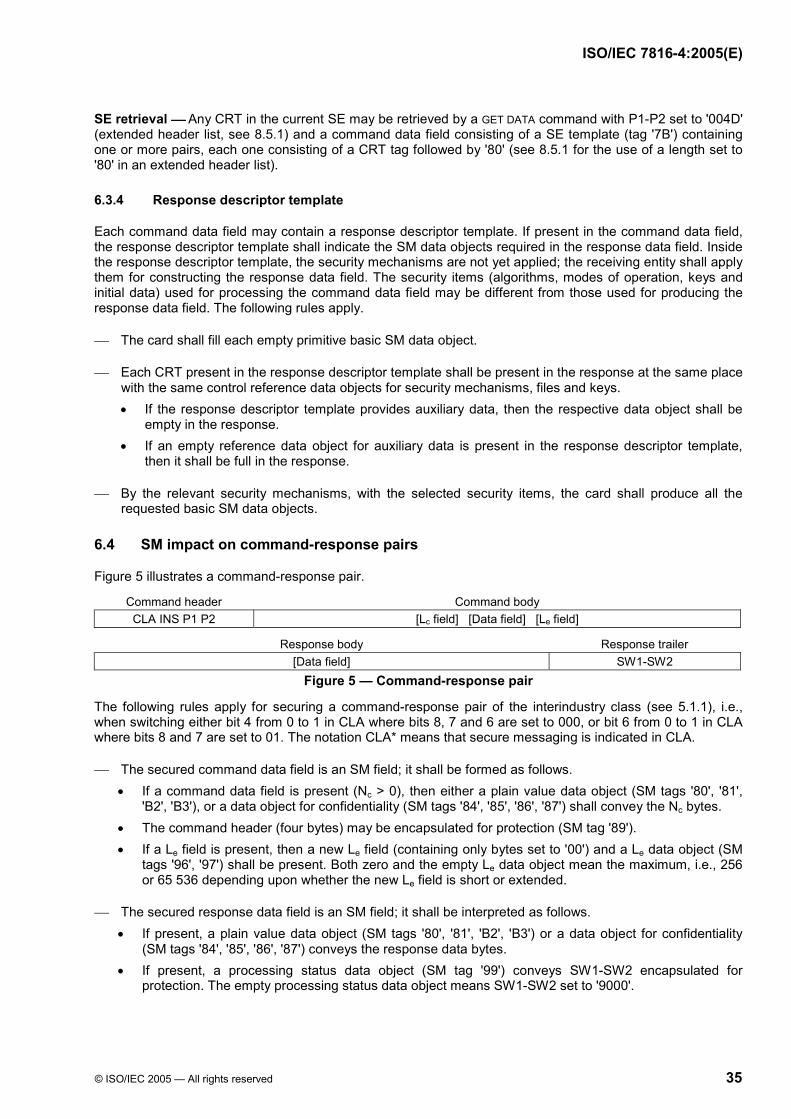
ISO/IEC 7816-4:2005(E)
© ISO/IEC 2005 — All rights reserved 35
SE retrieval Any CRT in the current SE may be retrieved by a GET DATA command with P1-P2 set to '004D' (extended header list, see 8.5.1) and a command data field consisting of a SE template (tag '7B') containing one or more pairs, each one consisting of a CRT tag followed by '80' (see 8.5.1 for the use of a length set to '80' in an extended header list).
6.3.4 Response descriptor template
Each command data field may contain a response descriptor template. If present in the command data field, the response descriptor template shall indicate the SM data objects required in the response data field. Inside the response descriptor template, the security mechanisms are not yet applied; the receiving entity shall apply them for constructing the response data field. The security items (algorithms, modes of operation, keys and initial data) used for processing the command data field may be different from those used for producing the response data field. The following rules apply.
The card shall fill each empty primitive basic SM data object.
Each CRT present in the response descriptor template shall be present in the response at the same place with the same control reference data objects for security mechanisms, files and keys. • If the response descriptor template provides auxiliary data, then the respective data object shall be
empty in the response. • If an empty reference data object for auxiliary data is present in the response descriptor template,
then it shall be full in the response.
By the relevant security mechanisms, with the selected security items, the card shall produce all the requested basic SM data objects.
6.4 SM impact on command-response pairs
Figure 5 illustrates a command-response pair.
Command header Command body CLA INS P1 P2 [Lc field] [Data field] [Le field]
Response body Response trailer [Data field] SW1-SW2
Figure 5 — Command-response pair
The following rules apply for securing a command-response pair of the interindustry class (see 5.1.1), i.e., when switching either bit 4 from 0 to 1 in CLA where bits 8, 7 and 6 are set to 000, or bit 6 from 0 to 1 in CLA where bits 8 and 7 are set to 01. The notation CLA* means that secure messaging is indicated in CLA.
The secured command data field is an SM field; it shall be formed as follows. • If a command data field is present (Nc > 0), then either a plain value data object (SM tags '80', '81',
'B2', 'B3'), or a data object for confidentiality (SM tags '84', '85', '86', '87') shall convey the Nc bytes. • The command header (four bytes) may be encapsulated for protection (SM tag '89'). • If a Le field is present, then a new Le field (containing only bytes set to '00') and a Le data object (SM
tags '96', '97') shall be present. Both zero and the empty Le data object mean the maximum, i.e., 256 or 65 536 depending upon whether the new Le field is short or extended.
The secured response data field is an SM field; it shall be interpreted as follows. • If present, a plain value data object (SM tags '80', '81', 'B2', 'B3') or a data object for confidentiality
(SM tags '84', '85', '86', '87') conveys the response data bytes. • If present, a processing status data object (SM tag '99') conveys SW1-SW2 encapsulated for
protection. The empty processing status data object means SW1-SW2 set to '9000'.

ISO/IEC 7816-4:2005(E)
36 © ISO/IEC 2005 — All rights reserved
Figure 6 shows the corresponding secured command-response pair.
Command header Command body CLA* INS P1 P2 [New Lc field] - {[Secured data field] = [T-Nc-Data bytes] - [T-'01' or '02'-Le]} - [New Le field]
Response body Response trailer [Secured data field] = [T-Nr-Data bytes] - [T-'02'-SW1-SW2] SW1-SW2
Figure 6 — Secured command-response pair
When bit 1 of INS is set to 1 (odd INS code, see 5.1.2), the unsecured data fields are encoded in BER-TLV and SM tags 'B2', 'B3', '84' and '85' shall be used for their encapsulation. Otherwise, as the format of the data fields to protect is not always apparent, SM tags '80', '81', '86' and '87' are recommended.
The secured data fields are SM fields; they may contain further or other SM data objects, e.g., a cryptographic checksum (SM tag '8E') or a digital signature (SM tag '9E') at the end.
The new Lc field encodes the number of bytes in the secured command data field.
The new Le field shall be absent when no data field is expected in the secured response data field; otherwise, it shall contain only bytes set to '00'.
The response trailer indicates the status of the receiving entity after processing the secured command. The following specific error conditions may occur. • If SW1-SW2 is set to '6987', then expected secure messaging data objects are missing. • If SW1-SW2 is set to '6988', then secure messaging data objects are incorrect.
Annex B provides illustrative examples of secure messaging.
7 Commands for interchange
This clause specifies commands for interchange, presented hereafter in six groups.
1) Selection
2) Data unit handling
3) Record handling
4) Data object handling
5) Basic security handling
6) Transmission handling
It shall not be mandatory for all cards complying with this document to support all those commands or all the options of a supported command. When interchange is required, a set of application-independent card services and related commands and options shall be used as specified in 8.
7.1 Selection
After the answer to reset, the MF or an application DF is implicitly selected through the basic logical channel (see 5.1.1.2), unless otherwise specified in the historical bytes (see 8.1.1) or in the initial data string (see 8.1.2).
7.1.1 SELECT command
When completed, the command opens the logical channel (see 5.1.1.2) numbered in CLA (see 5.1.1), if not yet opened, and sets a current structure within that logical channel. Subsequent commands may implicitly refer to the current structure through that logical channel.

ISO/IEC 7816-4:2005(E)
© ISO/IEC 2005 — All rights reserved 37
The selected DF (the MF or an application DF) becomes current in the logical channel. The previously selected DF, if any, is no longer referred to through that logical channel and becomes the former current DF. After such a selection, an implicit current EF may be referred to through that logical channel.
The selection of an EF sets a pair of current files: the EF and its parent DF.
Unless otherwise specified, the following rules apply to each open logical channel within a hierarchy of DFs. If the current EF is changed, or when there is no current EF, then the security status, if any, specific to the
former current EF is lost. If the current DF is a descendant of, or identical to the former current DF, then the security status specific
to the former current DF is maintained. If the current DF is neither a descendant of, nor identical to the former current DF, then the security status
specific to the former current DF is lost. The security status common to all common ancestors of the previous and new current DF is maintained.
Table 38 — SELECT command-response pair CLA As defined in 5.1.1 INS 'A4' P1 See Table 39 P2 See Table 40
Lc field Absent for encoding Nc = 0, present for encoding Nc > 0 Data field Absent or file identifier or path or DF name (according to P1)
Le field Absent for encoding Ne = 0, present for encoding Ne > 0
Data field Absent or file control information (according to P2) SW1-SW2 See Tables 5 and 6 when relevant, e.g., '6283', '6284', '6A80', '6A81', '6A82', '6A86', '6A87'
If P1 is set to '00', then the card knows whether the file to select is the MF, a DF or an EF, either because of a specific encoding of the file identifier, or because of the command processing context. If P2 is set to '00' and the command data field provides a file identifier, then that file identifier shall be
unique in the following three environments: the immediate children of the current DF, the parent DF and the immediate children of the parent DF.
If P2 is set to '00' and the command data field absent or set to '3F00', then the MF shall be selected.
If P1 is set to '04', then the command data field is a DF name, which may be an application identifier (see 8.2.1.2), possibly right truncated. If supported, successive such commands with the same data field shall select DFs whose names match with the data field, i.e., start with the command data field. If the card accepts the SELECT command without data field, then all or a subset of the DFs can be successively selected.
If the Le field contains only bytes set to '00', then all the bytes corresponding to the selection option should be returned within the limit of 256 for a short Le field, or 65 536 for an extended Le field. If the Le field is absent, i.e., for returning no file control information, then the response data field shall also be absent.
Table 39 — P1 b8 b7 b6 b5 b4 b3 b2 b1 Meaning Command data field 0 0 0 0 0 0 x x Selection by file identifier 0 0 0 0 0 0 0 0 Select MF, DF or EF File identifier or absent 0 0 0 0 0 0 0 1 Select child DF DF identifier 0 0 0 0 0 0 1 0 Select EF under the current DF EF identifier 0 0 0 0 0 0 1 1 Select parent DF of the current DF Absent 0 0 0 0 0 1 x x Selection by DF name 0 0 0 0 0 1 0 0 Select by DF name e.g., [truncated] application identifier 0 0 0 0 1 0 x x Selection by path 0 0 0 0 1 0 0 0 Select from the MF Path without the MF identifier 0 0 0 0 1 0 0 1 Select from the current DF Path without the current DF identifier
Any other value is reserved for future use by ISO/IEC JTC 1/SC 17. When present in the historical bytes (see 8.1.1) or in EF.ATR (see 8.2.1.1), the first software function table (see Table 86) indicates selection methods supported by the card.

ISO/IEC 7816-4:2005(E)
38 © ISO/IEC 2005 — All rights reserved
Table 40 — P2 b8 b7 b6 b5 b4 b3 b2 b1 Meaning 0 0 0 0 - - x x File occurrence 0 0 0 0 - - 0 0 — First or only occurrence 0 0 0 0 - - 0 1 — Last occurrence 0 0 0 0 - - 1 0 — Next occurrence 0 0 0 0 - - 1 1 — Previous occurrence 0 0 0 0 x x - - File control information (see 5.3.3 and Table 11) 0 0 0 0 0 0 - - — Return FCI template, optional use of FCI tag and length 0 0 0 0 0 1 - - — Return FCP template, mandatory use of FCP tag and length 0 0 0 0 1 0 - - — Return FMD template, mandatory use of FMD tag and length 0 0 0 0 1 1 - - — No response data if Le field absent, or proprietary if Le field present
Any other value is reserved for future use by ISO/IEC JTC 1/SC 17.
7.1.2 MANAGE CHANNEL command
When completed, the command opens or closes a logical channel (see 5.1.1.2) other than the basic one, i.e., a channel numbered from one to nineteen (the greater numbers are reserved for future use).
The open function opens a new logical channel other than the basic one. Options are provided for the card to assign a channel number, or for a channel number to be supplied to the card.
If bit 8 of P1 is set to 0 (i.e., P1 set to '00' because the other seven bits are reserved for future use), then MANAGE CHANNEL shall open a channel numbered from one to nineteen as follows. • If P2 is set to '00', then the Le field shall be set to '01' and the response data field shall consists of a
single byte for encoding a non-zero channel number assigned by the card from '01' to '13'. • If P2 is set from '01' to '13', then it encodes an externally assigned non-zero channel number and the
Le field shall be absent.
After an open function performed from the basic logical channel (CLA encoding zero as channel number), the MF or a default application DF shall be implicitly selected as the current DF on the new channel.
After an open function performed from a non-basic logical channel (CLA encoding a non-zero channel number), the current DF on the channel numbered in CLA shall become current on the new channel.
The close function explicitly closes a logical channel other than the basic one. The Le field shall be absent. After closing, the logical channel shall be available for re-use.
If bit 8 of P1 is set to 1 (i.e., P1 set to '80' because the other seven bits are reserved for future use), then MANAGE CHANNEL shall close a channel numbered from 1 to nineteen as follows. • If P2 is set to '00', then the channel numbered in CLA (a non-zero channel number) shall be closed. • If P2 is set from '01' to '13', then the channel numbered in P2 shall be closed.
Warning The close function may be aborted if CLA indicates neither the basic channel nor the channel numbered in P2.
Table 41 — MANAGE CHANNEL command-response pair CLA As defined in 5.1.1 INS '70'
P1-P2 '0000' for opening a logical channel to be numbered in the response data field '0001' to '0013' for opening the logical channel numbered in P2 '8000' for closing the logical channel numbered in CLA (other than the basic channel) '8001' to '8013' for closing the logical channel numbered in P2 (any other value of P1-P2 is reserved for future use)
Lc field Absent for encoding Nc = 0 Data field Absent
Le field Absent for encoding Ne = 0, present for encoding Ne = 1
Data field Absent (P1-P2 not set to '0000'), or '01' to '13' (P1-P2 set to '0000') SW1-SW2 See Tables 5 and 6 when relevant, e.g., '6200', '6881', '6A81'

ISO/IEC 7816-4:2005(E)
© ISO/IEC 2005 — All rights reserved 39
7.2 Data unit handling
7.2.1 Data units
Within each EF supporting data units, an offset shall reference each data unit. From zero for the first data unit of the EF, the offset is incremented by one for each subsequent data unit. The offset data element is binary encoded on the minimum number of bytes. Reference to a data unit not contained in the EF is an error.
The card can provide a data coding byte (see Table 87) in the historical bytes (see 8.1.1), in EF.ATR (see 8.2.1.1) and in the control information of any file (see tag '82' in Table 12). The data coding byte fixes a data unit size. If the card provides data coding bytes in several places, then the data coding byte valid for a given EF is
in the closest position to that EF within the path from the MF to that EF. In the absence of indication within the path, the data unit size is one byte (default value) for that EF.
7.2.2 General
Any command of this group shall be aborted if applied to an EF not supporting data units. It can be performed on an EF only if the security status satisfies the security attributes defined for the function, namely, read, write, update, erase or search.
Each command of this group may use either a short EF identifier or a file identifier. If there is a current EF at the time of issuing the command, then the process may be completed on that EF by just setting all the corresponding bits to 0. If the process is completed, then the identified EF becomes current.
INS P1 P2 All the commands of this group shall use bit 1 of INS and bit 8 of P1 as follows. If bit 1 of INS is set to 0 and bit 8 of P1 to 1, then bits 7 and 6 of P1 are set to 00 (RFU), bits 5 to 1 of P1
encode a short EF identifier and P2 (eight bits) encodes an offset from zero to 255. If bit 1 of INS is set to 0 and bit 8 of P1 to 0, then P1-P2 (fifteen bits) encodes an offset from zero to
32 767. If bit 1 of INS is set to 1, then P1-P2 shall identify an EF. If the first eleven bits of P1-P2 are set to 0 and if
bits 5 to 1 of P2 are not all equal and if the card and / or the EF supports selection by short EF identifier, then bits 5 to 1 of P2 encode a short EF identifier (a number from one to thirty). Otherwise, P1-P2 is a file identifier. P1-P2 set to '0000' identifies the current EF. At least one offset data object with tag '54' shall be present in the command data field. When present in a command or response data field, data shall be encapsulated in a discretionary data object with tag '53' or '73'.
In this group of commands, SW1-SW2 set to '63CX' indicates a successful change of memory state, but after an internal retry routine; 'X' > '0' encodes the number of retries; 'X' = '0' means that no counter is provided.
7.2.3 READ BINARY command
The response data field gives [part of] the content of an EF supporting data units.
If the Le field contains only bytes set to '00', then all the bytes until the end of the file should be read within the limit of 256 for a short Le field, or 65 536 for an extended Le field.
Table 42 — READ BINARY command-response pair CLA As defined in 5.1.1 INS 'B0' or 'B1'
P1-P2 See 7.2.2 Lc field Absent for encoding Nc = 0, present for encoding Nc > 0
Data field Absent (INS = 'B0'), or offset data object (INS = 'B1') Le field Present for encoding Ne > 0
Data field Data read (INS = 'B0'), or discretionary data object for encapsulating data read (INS = 'B1') SW1-SW2 See Tables 5 and 6 when relevant, e.g., '6281', '6282', '6700', '6981', '6982', '6986', '6A81', '6A82', '6B00', '6CXX'

ISO/IEC 7816-4:2005(E)
40 © ISO/IEC 2005 — All rights reserved
7.2.4 WRITE BINARY command
The command initiates one of the following operations into an EF according to the file attributes:
the write-once of the bits given in the command data field (the command shall be aborted if the string of data units is not in the logical erased state);
the logical-OR of the bits already present in the card with the bits given in the command data field (the logical erased state of the bits of the file is zero);
the logical-AND of the bits already present in the card with the bits given in the command data field (the logical erased state of the bits of the file is one).
By default, i.e., when the data coding byte (see Table 87) is absent in the historical bytes (see 8.1.1), in EF.ATR (see 8.2.1.1) and in the control parameters (see tag '82' in Table 12) of every file within the path from the MF to a given EF, the logical-OR shall apply for that EF.
Table 43 — WRITE BINARY command-response pair CLA As defined in 5.1.1 INS 'D0' or 'D1'
P1-P2 See 7.2.2 Lc field Present for encoding Nc > 0
Data field String of data units to be written (INS = 'D0'), or offset data object and discretionary data object for encapsulating the string of data units to be written (INS = 'D1')
Le field Absent for encoding Ne = 0 Data field Absent SW1-SW2 See Tables 5 and 6 when relevant, e.g., '63CX' (see 7.2.2), '6581', '6700', '6981', '6982', '6B00' (offset outside the EF)
7.2.5 UPDATE BINARY command
The command initiates the update of bits already present in an EF with the bits given in the command data field. When the process is completed, each bit of each specified data unit will have the value specified in the command data field.
Table 44 — UPDATE BINARY command-response pair CLA As defined in 5.1.1 INS 'D6' or 'D7'
P1-P2 See 7.2.2 Lc field Present for encoding Nc > 0
Data field String of data units to be updated (INS = 'D6'), or offset data object and discretionary data object for encapsulating the string of updating data units (INS = 'D7')
Le field Absent for encoding Ne = 0 Data field Absent SW1-SW2 See Tables 5 and 6 when relevant, e.g., '63CX' (see 7.2.2), '6581', '6700', '6981', '6982', '6B00' (offset outside the EF)
7.2.6 SEARCH BINARY command
The command initiates a search within an EF supporting data units. The response data field gives the offset of a data unit: the byte string at the returned offset within the EF shall have the same value as the search string in the command data field. The response data field is absent either because the Le field is absent, or because no match is found. If the search string is absent, then the response data field gives the offset of the first data unit in a logically erased state.

ISO/IEC 7816-4:2005(E)
© ISO/IEC 2005 — All rights reserved 41
Table 45 — SEARCH BINARY command-response pair CLA As defined in 5.1.1 INS 'A0' or 'A1'
P1-P2 See 7.2.2 Lc field Absent for encoding Nc = 0, present for encoding Nc > 0
Data field Absent or search string (INS = 'A0'), or offset data object and discretionary data object for encapsulating the search string (INS = 'A1')
Le field Absent for encoding Ne = 0, present for encoding Ne > 0
Data field Absent or offset of the first data unit matching the command data field (INS = 'A0'), or offset data object indicating the first data unit matching the search string (INS = 'A1')
SW1-SW2 See Tables 5 and 6 when relevant, e.g., '6282', '6982' 7.2.7 ERASE BINARY command
The command sets [part of] the content of an EF to its logical erased state, sequentially, starting from a given offset. If INS = '0E', then, if present, the command data field encodes the offset of the first data unit not to be
erased. This offset shall be higher than the one encoded in P1-P2. If the data field is absent, then the command erases up to the end of the file.
If INS = '0F', then, if present, the command data field shall consist of zero, one or two offset data objects. If there is no offset, then the command erases all the data units in the file. If there is one offset, it indicates the first data unit to be erased; then the command erases up to the end of the file. Two offsets define a sequence of data units: the second offset indicates the first data unit not to be erased; it shall be higher than the first offset.
Table 46 — ERASE BINARY command-response pair CLA As defined in 5.1.1 INS '0E' or '0F'
P1-P2 See 7.2.2 Lc field Absent for encoding Nc = 0, present for encoding Nc > 0
Data field Absent or offset of the first data unit not to be erased (INS = '0E'), or Absent or one or two offset data objects (INS = '0F')
Le field Absent for encoding Ne = 0
Data field Absent SW1-SW2 See Tables 5 and 6 when relevant, e.g., '63CX' (see 7.2.2), '6581', '6700', '6981', '6982', '6B00' (offset outside the EF)
7.3 Record handling
7.3.1 Records
Within each EF supporting records, a record number and / or a record identifier shall reference each record. Reference to a record not contained in the EF is an error.
Referencing by record number — Each record number is unique and sequential. Within each EF supporting a linear structure, the record numbers shall be sequentially assigned when
writing or appending, i.e., in the order of creation; the first record (number one) is the first created record. Within each EF supporting a cyclic structure, the record numbers shall be sequentially assigned in the
opposite order, i.e., the first record (number one) is the most recently created record.
The following additional rule is defined for linear structures and for cyclic structures. Zero shall refer to the current record, i.e., that record referenced by the record pointer.

ISO/IEC 7816-4:2005(E)
42 © ISO/IEC 2005 — All rights reserved
Referencing by record identifier — Each record identifier is provided by an application. Several records may have the same record identifier, in which case data contained in the records may be used for discriminating between them. If a record is a SIMPLE-TLV data object in a data field, then the record identifier is the first byte of the data object, i.e., the SIMPLE-TLV tag.
Referencing by record identifier shall induce the management of a record pointer. A reset of the card, a SELECT and any command using a valid short EF identifier for accessing an EF can affect the record pointer. Referencing by record number shall not affect the record pointer.
Each time a reference is made with a record identifier, the logical position of the target record shall be indicated: the first or last occurrence, the next or previous occurrence relative to the record pointer. Within each EF supporting a linear structure, the logical positions shall be sequentially assigned when
writing or appending, i.e., in the order of creation. The first created record is in the first logical position. Within each EF supporting a cyclic structure, the logical positions shall be sequentially assigned in the
opposite order, i.e., the most recently created record is in the first logical position.
The following additional rules are defined for linear structures and for cyclic structures. The first occurrence shall be the record with the specified identifier and in the first logical position; the last
occurrence shall be the record with the specified identifier and in the last logical position. If there is a current record, then the next occurrence shall be the closest record with the specified
identifier but in a greater logical position than the current record; the previous occurrence shall be the closest record with the specified identifier but in a smaller logical position than the current record.
If there is no current record, then the next occurrence shall be equivalent to the first occurrence; the previous occurrence shall be equivalent to the last occurrence.
Zero shall refer to the first, last, next or previous record in the numbering sequence, independently from the record identifier.
7.3.2 General
Any command of this group shall be aborted if applied to an EF not supporting records. It can be performed on an EF only if the security status satisfies the security attributes defined for the function, namely, read, write, append, update, search or erase.
Two commands of this group (read, update) may use an odd INS code (data fields encoded in BER-TLV) for initiating an action on a part of a given record (partial read, partial update). Then an offset shall reference each byte inside a record: from zero for the first byte of the record, the offset is incremented by one for each subsequent byte of the record. Reference to a byte not contained in the record is an error. As needed, the offset data element is binary encoded and referenced by tag '54'. When present in a command or response data field, data shall be encapsulated in a discretionary data object with tag '53' or '73'.
Each command of this group may use a short EF identifier. If the process is completed, then the identified EF becomes current and the record pointer is reset. If there is a current EF at the time of issuing the command, then the process may be completed without indicating the EF (by just setting the corresponding five bits to 0).
P1 Each record number or identifier is a number from one to 254, encoded by a value of P1 from '01' to 'FE'. Zero (encoded '00') is reserved for special purposes. 255 (encoded 'FF') is reserved for future use.
P2 Bits 8 to 4 are a short EF identifier according to Table 47. Bits 3 to 1 depend upon the command.
Table 47 — Short EF identifier in P2 b8 b7 b6 b5 b4 b3 b2 b1 Meaning 0 0 0 0 0 - - - Current EF
Not all equal - - - Short EF identifier (a number from one to thirty) 1 1 1 1 1 - - - Reserved for future use
In this group of commands, SW1-SW2 set to '63CX' indicates a successful change of memory state, but after an internal retry routine; 'X' > '0' encodes the number of retries; 'X' = '0' means that no counter is provided.

ISO/IEC 7816-4:2005(E)
© ISO/IEC 2005 — All rights reserved 43
7.3.3 READ RECORD (S) command
The response data field gives the [partial] contents of the specified record(s) [or the beginning part of one record] within an EF.
If INS = 'B2' and if the records are SIMPLE-TLV data objects (see 5.2.1), then Table 50 illustrates the response data field. The comparison of Nr with the TLV structure indicates whether the unique record (read one record) or the last record (read all records) is incomplete, complete or padded.
NOTE If the records are not data objects, then the read-all-records function results in receiving records without delimitation.
If INS = 'B3', then the command partially reads the record referenced by P1. The command data field shall contain an offset data object (tag '54) indicating the first byte to be read in the record. The response data field shall contain a discretionary data object (tag '53') encapsulating the data read.
Table 48 — READ RECORD (S) command-response pair CLA As defined in 5.1.1 INS 'B2' or 'B3' P1 Record number or record identifier ('00' references the current record) P2 See Table 49
Lc field Absent for encoding Nc = 0, present for encoding Nc > 0 Data field Absent (INS = 'B2'), or offset data object (INS = 'B3')
Le field Present for encoding Ne > 0
Data field Data read (INS = 'B2'), or discretionary data object for encapsulating the data read (INS = 'B3') SW1-SW2 See Tables 5 and 6 when relevant, e.g., '6281, '6282', '6700', '6981', '6982', '6A81, '6A82', '6A83', '6CXX'
Table 49 — P2 b8 b7 b6 b5 b4 b3 b2 b1 Meaning x x x x x - - - Short EF identifier according to Table 47 - - - - - 0 x x Record identifier in P1 - - - - - 0 0 0 — Read first occurrence - - - - - 0 0 1 — Read last occurrence - - - - - 0 1 0 — Read next occurrence - - - - - 0 1 1 — Read previous occurrence - - - - - 1 x x Record number in P1 - - - - - 1 0 0 — Read record P1 - - - - - 1 0 1 — Read all records from P1 up to the last - - - - - 1 1 0 — Read all records from the last up to P1 1 1 1 Reserved for future use
If the Le field contains only bytes set to '00', then the command should read completely either the single requested record, or the requested sequence of records, depending on bits 3, 2 and 1 of P2 and within the limit of 256 for a short Le field, or 65 536 for an extended Le field.
Table 50 — Response data fields with INS = 'B2' Case a — Partial read of one record (the Le field does not contain only bytes set to '00')
Tn (one byte) Ln (one or three bytes) First bytes of Vn <------------------------------------------------------------------------- Nr bytes --------------------------------------------------------------------->
Case b — Complete read of one record (the Le field contains only bytes set to '00') Tn (one byte) Ln (one or three bytes) All the bytes of Vn
Case c — Partial read of a sequence of records (the Le field does not contain only bytes set to '00') Tn - Ln - Vn … Tn+m - Ln+m - Vn+m (First bytes of the record)
<-------------------------------------------------------------------- Nr bytes -------------------------------------------------------------------------->
Case d — Read several records up to the file end (the Le field contains only bytes set to '00') Tn - Ln - Vn … Tn+m - Ln+m - Vn+m

ISO/IEC 7816-4:2005(E)
44 © ISO/IEC 2005 — All rights reserved
7.3.4 WRITE RECORD command
The command initiates one of the following operations within an EF:
the write-once of a record given in the command data field (the command shall be aborted if the record is not in the logical erased state);
the logical-OR of the data bytes of a record already present in the card with the data bytes of the record given in the command data field;
the logical-AND of the data bytes of a record already present in the card with the data bytes of the record given in the command data field.
By default, i.e., when the data coding byte (see Table 87) is absent in the historical bytes (see 8.1.1), in EF.ATR (see 8.2.1.1) and in the control parameters (see tag '82' in Table 12) of every file within the path from the MF to a given EF, the logical-OR shall apply for that EF.
When using current record addressing, the command shall set the record pointer on the successfully written record.
If applied to an EF supporting a cyclic structure with records of fixed size, the “previous” option (bits 3, 2 and 1 of P2 set to 011) behaves as APPEND RECORD.
If the records are SIMPLE-TLV data objects (see 5.2.1), then Table 53 illustrates the command data field.
Table 51 — WRITE RECORD command-response pair CLA As defined in 5.1.1 INS 'D2' P1 Record number ('00' references the current record) P2 See Table 52
Lc field Present for encoding Nc > 0 Data field Record to be written
Le field Absent for encoding Ne = 0
Data field Absent SW1-SW2 See Tables 5 and 6 when relevant, e.g., '63CX' (see 7.3.2), '6581', '6700', '6981', '6982', '6986', '6A81', '6A82', '6A83,
'6A84', '6A85'
Table 52 — P2 b8 b7 b6 b5 b4 b3 b2 b1 Meaning x x x x x - - - Short EF identifier according to Table 47 - - - - - 0 x x P1 set to '00' - - - - - 0 0 0 — First record - - - - - 0 0 1 — Last record - - - - - 0 1 0 — Next record - - - - - 0 1 1 — Previous record - - - - - 1 0 0 Record number in P1
Any other value is reserved for future use by ISO/IEC JTC 1/SC 17.
Table 53 — Command data field (one complete record) Tn (one byte) Ln (one or three bytes) All the bytes of Vn
7.3.5 UPDATE RECORD command
The command initiates the update of a specific record with the bits given in the command data field. When using current record addressing, the command shall set the record pointer on the updated record.
If applied to an EF supporting a linear or cyclic structure with records of fixed size, then the command shall be aborted if the record size is different from the size of the existing record.

ISO/IEC 7816-4:2005(E)
© ISO/IEC 2005 — All rights reserved 45
If applied to an EF supporting a linear structure with records of variable size, then the command may be carried out when the record size is different from the size of the existing record.
If applied to an EF supporting a cyclic structure with records of fixed size, the “previous” option (bits 3, 2 and 1 of P2 set to 011) behaves as APPEND RECORD.
Table 54 — UPDATE RECORD command-response pair CLA As defined in 5.1.1 INS 'DC' or 'DD' P1 Record number ('00' references the current record) P2 See Table 52 (INS = 'DC') or 55 (INS = 'DD')
Lc field Present for encoding Nc > 0 Data field Updating data (INS = 'DC'), or offset data object and discretionary data object for encapsulating the
updating data (INS = 'DD') Le field Absent for encoding Ne = 0
Data field Absent SW1-SW2 See Tables 5 and 6 when relevant, e.g., '63CX' (see 7.3.2), '6581', '6700', '6981', '6982', '6986', '6A81', '6A82', '6A83,
'6A84', '6A85'
If INS = 'DC' and if the records are SIMPLE-TLV data objects (see 5.2.1), then Table 53 illustrates the command data field.
If INS = 'DD', then the command partially updates the record referenced by P1. The command data field shall contain an offset data object (tag '54') for indicating the first byte to be updated in the record and a discretionary data object (tag '53' or '73') for encapsulating the updating data.
Table 55 — P2 with INS = 'DD' b8 b7 b6 b5 b4 b3 b2 b1 Meaning x x x x x - - - Short EF identifier according to Table 47 - - - - - 1 x x Record number in P1 - - - - - 1 0 0 — Replace - - - - - 1 0 1 — Logical AND - - - - - 1 1 0 — Logical OR - - - - - 1 1 1 — Logical XOR
Any other value is reserved for future use by ISO/IEC JTC 1/SC 17. 7.3.6 APPEND RECORD command
The command initiates either the writing of a new record at the end of an EF supporting a linear structure, or the writing of record number one in an EF supporting a cyclic structure. When using current record addressing, the command shall set the record pointer on the successfully appended record.
If the command applies to an EF supporting a linear structure full of records, then the command is aborted because there is not enough memory space in the file.
If the command applies to an EF supporting a cyclic structure full of records, then the record with the highest record number is replaced. This record becomes record number one.
If the records are SIMPLE-TLV data objects (see 5.2.1), then Table 53 illustrates the command data field.

ISO/IEC 7816-4:2005(E)
46 © ISO/IEC 2005 — All rights reserved
Table 56 — APPEND RECORD command-response pair CLA As defined in 5.1.1 INS 'E2' P1 '00' (any other value is invalid) P2 See Table 47 with bits 3 to 1 set to 000 (any other value is reserved for future use)
Lc field Present for encoding Nc > 0 Data field Record to be appended
Le field Absent for encoding Ne = 0
Data field Absent SW1-SW2 See Tables 5 and 6 when relevant, e.g., '63CX' (see 7.3.2), '6581', '6700', '6981', '6982', '6986', '6A81', '6A82', '6A83,
'6A84', '6A85'
7.3.7 SEARCH RECORD command
The command initiates a simple or enhanced or proprietary search on records stored within an EF. The search can be limited to records with a given identifier or to records with a number greater or smaller than a given number. It can be performed in increasing or in decreasing order of record numbers. The search starts either from the first byte of the records (simple search), or from a given offset within the records (enhanced search), or from the first occurrence of a given byte within the records (enhanced search). The response data field gives the numbers of the records matching the search criteria within an EF supporting records. The command shall set the record pointer on the first record matching the search criteria.
In an EF supporting records of variable size with linear structure, the search shall not take into account the records shorter than the search string. In an EF supporting records of fixed size with linear or cyclic structure, if the search string is longer than the records, then the card shall abort the command.
Table 57 — SEARCH RECORD command-response pair CLA As defined in 5.1.1 INS 'A2' P1 Record number or record identifier ('00' references the current record) P2 See Table 58
Lc field Present for encoding Nc > 0 Data field Search string (bits 3 and 2 of P2 not set to 11, simple search), or
Search indication (2 bytes) followed by search string (bits 3, 2 and 1 of P2 set to 110, enhanced search), orProprietary (bits 3, 2 and 1 of P2 set to 111, proprietary search)
Le field Absent for encoding Ne = 0, present for encoding Ne > 0
Data field Absent or record numbers SW1-SW2 See Tables 5 and 6 when relevant, e.g., '6282', '6982', '6CXX' The response data field is absent either because the Le field is absent, or because no match is found. The response data field does not give record identifiers because they may not be unique.
Table 58 — P2 b8 b7 b6 b5 b4 b3 b2 b1 Meaning x x x x x - - - Short EF identifier according to Table 47 - - - - - 0 x x Simple search with record identifier in P1 - - - - - 0 0 0 — Forward from first occurrence - - - - - 0 0 1 — Backward from last occurrence - - - - - 0 1 0 — Forward from next occurrence - - - - - 0 1 1 — Backward from previous occurrence - - - - - 1 0 x Simple search with record number in P1 - - - - - 1 0 0 — Forward from P1 - - - - - 1 0 1 — Backward from P1 - - - - - 1 1 0 Enhanced search (see Table 59) - - - - - 1 1 1 Proprietary search
In an enhanced search (bits 3, 2 and 1 of P2 set to 110), the command data field consists of a search indica-tion on two bytes followed by a search string. Table 59 specifies the first search indication byte. According to

ISO/IEC 7816-4:2005(E)
© ISO/IEC 2005 — All rights reserved 47
the first byte of the search indication, the second byte is either an offset or a value, i.e., the search in the records shall start either from this offset (absolute position) or after the first occurrence of this value.
Table 59 — First byte of the search indication b8 b7 b6 b5 b4 b3 b2 b1 Meaning 0 0 0 0 0 - - - The subsequent byte is an offset (start from that position) 0 0 0 0 1 - - - The subsequent byte is a value (start after the first occurrence) - - - - - 0 x x Record identifier in P1 - - - - - 0 0 0 — Forward from first occurrence - - - - - 0 0 1 — Backward from last occurrence - - - - - 0 1 0 — Forward from next occurrence - - - - - 0 1 1 — Backward from previous occurrence - - - - - 1 x x Record number in P1 - - - - - 1 0 0 — Forward from P1 - - - - - 1 0 1 — Backward from P1 - - - - - 1 1 0 — Forward from next record - - - - - 1 1 1 — Backward from previous record
Any other value is reserved for future use by ISO/IEC JTC 1/SC 17.
7.3.8 ERASE RECORD (S) command
The command sets one or more records of an EF to the logical erased state, either the record referenced by P1, or the sequence of records from P1, sequentially, up to the end of the file. Erased records shall not be deleted, and may still be accessible by WRITE RECORD and UPDATE RECORD commands.
Table 60 — ERASE RECORD (S) command-response pair CLA As defined in 5.1.1 INS '0C' P1 Record number P2 See Table 61
Lc field Absent for encoding Nc = 0 Data field Absent
Le field Absent for encoding Ne = 0
Data field Absent SW1-SW2 See Tables 5 and 6 when relevant, e.g., '63CX' (see 7.3.2), '6581', '6700', '6981', '6982', '6986', '6A81', '6A82', '6A83,
'6A84', '6A85'
Table 61 — P2 b8 b7 b6 b5 b4 b3 b2 b1 Meaning x x x x x - - - Short EF identifier according to Table 47 - - - - - 1 x x Record number in P1 - - - - - 1 0 0 — Erase record P1 - - - - - 1 0 1 — Erase all records from P1 up to the last
Any other value is reserved for future use by ISO/IEC JTC 1/SC 17. 7.4 Data object handling
7.4.1 General
Any command of this group shall be aborted if applied to a structure (DF or EF) not supporting data objects. It can be performed only if the security status satisfies the security conditions defined by the application within the context for the function.
INS P1 P2 All the commands of this group may use an odd INS code (see 5.1.2). Bit 1 of INS shall be used together with P1-P2 according to Table 62.

ISO/IEC 7816-4:2005(E)
48 © ISO/IEC 2005 — All rights reserved
Table 62 — P1-P2 Condition Value of P1-P2 Meaning
Even INS code '0000' Used for dumping a file (see 8.4), or for card-originated byte strings (see 8.6) '0040' to '00FF' BER-TLV tag (one byte) in P2 '0100' to '01FF' Proprietary '0200' to '02FF' SIMPLE-TLV tag in P2 '4000' to 'FFFF' BER-TLV tag (two bytes) in P1-P2
Odd INS code Any value File identifier or short EF identifier (see text below) Any other value is reserved for future use by ISO/IEC JTC 1/SC 17.
If bit 1 of INS is set to 0 and P1 to '00', then P2 from '40' to 'FE' shall be a BER-TLV tag on a single byte. If the BER-TLV tag is valid and indicates a constructed encoding, then the command sets the corresponding template as current context. The value '00FF' is used either for obtaining all the common BER-TLV data objects readable in the context, or for indicating that the command data field is encoded in BER-TLV.
If bit 1 of INS is set to 0 and P1 to '01', then P2 from '00' to 'FF' shall be an identifier for card internal tests and for proprietary services meaningful within a given application context.
If bit 1 of INS is set to 0 and P1 to '02', then P2 from '01' to 'FE' shall be a SIMPLE-TLV tag. The value '0200' is reserved for future use. The value '02FF' is used either for obtaining all the common SIMPLE-TLV data objects readable in the context or for indicating that the command data field is encoded in SIMPLE-TLV.
If bit 1 of INS is set to 0 and if P1-P2 lies from '4000' to 'FFFF', then they shall be a BER-TLV tag on two bytes. If the BER-TLV tag is valid and indicates a constructed encoding, then the command sets the corresponding template as current context. The values that are not valid BER-TLV tags on two bytes (see 5.2.2.1) are reserved for future use, e.g., '4000' and 'FFFF'.
If bit 1 of INS is set to 1, then P1-P2 shall identify a file. If the first eleven bits of P1-P2 are set to 0 and if bits 5 to 1 of P2 are not all equal and if the card and / or the file supports selection by short EF identifier, then bits 5 to 1 of P2 encode a short EF identifier (a number from one to thirty). Otherwise, P1-P2 is a file identifier. P1-P2 set to '3FFF' identifies the current DF. P1-P2 set to '0000' identifies the current EF, unless the command data field provides a file reference data object (tag '51', see 5.3.1.2) for identifying a file. If the process is completed, then the identified file becomes current.
Data fields The commands of this group shall use the data fields as follows.
If bit 1 of INS is set to 0, if a data object is requested or provided within the current context (e.g., application-specific environment or current DF), then the data field or the concatenation of the data fields shall contain the value field of the data object, i.e., either the referred data element in the case of a SIMPLE-TLV data object or a primitive BER-TLV data object, or the referred template in the case of a constructed BER-TLV data object.
With both INS codes, if a set of data objects is provided or if the content of an EF is requested, then the appropriate data field shall contain the data object(s).
7.4.2 GET DATA command
The command retrieves either the content of an EF supporting data objects, or one data object, possibly constructed, within the current context (e.g., application-specific environment or current DF).
NOTE If the information is too long for a single response data field, then the card shall return the beginning of the information followed by SW1-SW2 set to '61XX'. Then a subsequent GET RESPONSE provides 'XX' bytes of information. The process may be repeated until the card sends SW1-SW2 set to '9000'.
If INS = 'CB', then the command data field shall contain either a tag list data object, or a header list data object, or an extended header list data object (tags '5C', '5D', '4D', see 8.5.1). In the tag list case, the response data field shall be the concatenation of the data objects referenced in
the tag list, in the same order (one or more data objects may be absent). An empty tag list requires all the available data objects.

ISO/IEC 7816-4:2005(E)
© ISO/IEC 2005 — All rights reserved 49
In the header list case, the response data field shall be the concatenation of the truncated data objects referenced in the header list, in the same order (one or more data objects may be absent).
In the extended header list case, the response data field shall be the concatenation of the data objects derived from the extended header list according to 8.5.1.
When there are several occurrences of a tag, this clause does not define which data object is returned because that depends on the definition or the nature or the content of the data object.
If the physical interface does not allow the card to answer to reset, e.g., a universal serial bus or an access by radio frequency, then the GET DATA command may retrieve specific information in the card according to P1-P2. Either one of the following specific information may be retrieved in the card.
With INS = 'CA', • Tag '5F51' the Answer-to-Reset is a string of up to 32 bytes according to ISO/IEC 7816-3. • Tag '5F52' the historical bytes are a string of up to 15 bytes according to 8.1.1.
With INS = 'CB' and an empty tag list, i.e., '5C00', in the command data field, • File identifier '2F00' the content of EF.DIR is a set of BER-TLV data objects according to 8.2.1.1. • File identifier '2F01' the content of EF.ATR is a set of BER-TLV data objects according to 8.2.1.1.
NOTE 1 (Background Information) According to the physical interface specified in ISO/IEC 7816-3, the card answers to any cold or warm reset operation through the contacts. The answer to reset is a sequence of asynchronous characters. The initial character TS indicates conventions for decoding bytes in characters and offers an alternate measurement of the elementary time unit. Despite it may be decoded according to the indicated conventions, TS is a synchronization pattern, not a byte. According to ISO/IEC 7816-3, the Answer-to-Reset is the string of up to 32 bytes conveyed by the answer to reset, namely a mandatory format byte T0 followed by optional interface bytes, optional historical bytes (up to 15 historical bytes encoded according to 8.1.1) and a conditional check byte TCK. When TCK is present, the exclusive-oring of all the bytes T0 to TCK inclusive is null.
NOTE 2 For ATR information, if the Le field encodes a number less than the exact length, then rather than returning the beginning of the information followed by SW1-SW2 set to '61XX', the card should preferably abort the command by returning only SW1-SW2 set to '6CYY' for indicating the exact number of available data bytes. However, '6C00' indicates 256 bytes or more. If it is more than 256, then SW1-SW2 set to '61XX' indicates that 'XX' bytes are still available.
If the Le field contains only bytes set to '00', then all the required information should be returned within the limit of 256 for a short Le field, or 65 536 for an extended Le field.
Table 63 — GET DATA command-response pair CLA As defined in 5.1.1 INS 'CA' or 'CB'
P1-P2 See Table 62 Lc field Absent for encoding Nc = 0, present for encoding Nc > 0
Data field Absent (INS = 'CA'), or tag list data object or (extended) header list data object (INS = 'CB') Le field Present for encoding Ne > 0
Data field Data bytes according to P1-P2 (INS = 'CA'), or concatenation of BER-TLV data objects (INS = 'CB') SW1-SW2 See Tables 5 and 6 when relevant, e.g., '61XX', '6202' to '6280', '6281', '6700', '6981', '6982', '6985', '6A81', '6A88'
(data objects not found, i.e., referenced data not found), '6CXX'
7.4.3 PUT DATA command
The command initiates the management of either the content of an EF supporting data objects, or one data object, possibly constructed, within the current context (e.g., application-specific environment or current DF). For example, it allows sending a command-to-perform (tag '52') or a cardholder certificate (tag '7F21'), possibly too long for a single command. If the data object is too long for a single command, then command chaining shall apply (see 5.1.1.1); the value field of the data object is the concatenation of the command data fields.

ISO/IEC 7816-4:2005(E)
50 © ISO/IEC 2005 — All rights reserved
The definition or the nature or the content of the data objects shall induce the exact management functions, e.g., writing once and / or updating and / or appending.
SW1-SW2 set to '63CX' indicates a successful change of memory state, but after an internal retry routine; 'X' > '0' encodes the number of retries; 'X' = '0' means that no counter is provided.
Table 64 — PUT DATA command-response pair CLA As defined in 5.1.1 INS 'DA' or 'DB'
P1-P2 See Table 62 Lc field Present for encoding Nc > 0
Data field Data bytes according to P1-P2 (INS = 'DA'), or concatenation of BER-TLV data objects (INS = 'DB') Le field Absent for encoding Ne = 0
Data field Absent SW1-SW2 See Tables 5 and 6 when relevant, e.g., '63CX', '6581', '6700', '6981', '6982', '6985', '6A80', '6A81', '6A84', '6A85'
7.5 Basic security handling
7.5.1 General
The commands of this group reserve P1-P2 for referencing an algorithm and some related reference data (e.g., a key). If there is a current key and a current algorithm, then the command may implicitly use them.
P1 Unless otherwise specified, P1 references the algorithm to use: either a cryptographic algorithm, or a biometric algorithm (see ISO/IEC 7816-11[4]). P1 set to '00' means that no information is given, i.e., either the reference is known before issuing the command, or the command data field provides it.
P2 Unless otherwise specified, P2 qualifies reference data according to Table 65. P2 set to '00' means that no information is given, i.e., either the qualifier is known before issuing the command, or the command data field provides it. The qualifier may be for example a password number or a key number or a short EF identifier.
Table 65 — P2 b8 b7 b6 b5 b4 b3 b2 b1 Meaning 0 0 0 0 0 0 0 0 No information given 0 - - - - - - - Global reference data (e.g., MF specific password or key) 1 - - - - - - - Specific reference data (e.g., DF specific password or key) - x x - - - - - 00 (any other value is reserved for future use) - - - x x x x x Qualifier, i.e., number of the reference data or number of the secret
NOTE A MANAGE SECURITY ENVIRONMENT command may set an algorithm reference and / or a reference data qualifier.
In this group of commands, SW1-SW2 set to '6300' or '63CX' indicates that the verification failed, 'X' > '0' encodes the number of further allowed retries. SW1-SW2 set to '6A88' means “reference data not found”.
7.5.2 INTERNAL AUTHENTICATE command
The command initiates the computation of authentication data by the card using the challenge data sent by the interface device and a relevant secret (e.g., a key) stored in the card.
If the relevant secret is attached to the MF, then the command may be used to authenticate the card as a whole.
If the relevant secret is attached to another DF, then the command may be used to authenticate that DF.
Any successful authentication may be subject to completion of prior commands (e.g., VERIFY, SELECT) or selections (e.g., the relevant secret).

ISO/IEC 7816-4:2005(E)
© ISO/IEC 2005 — All rights reserved 51
The card may record the number of times the command is issued, in order to limit the number of further uses of the relevant secret or the algorithm.
NOTE The response data field may include data useful for further security functions (e.g., random number).
Table 66 — INTERNAL AUTHENTICATE command-response pair CLA As defined in 5.1.1 INS '88'
P1-P2 See 7.5.1 and Table 65 Lc field Present for encoding Nc > 0
Data field Authentication-related data (e.g., challenge) Le field Present for encoding Ne > 0
Data field Authentication-related data (e.g., response to a challenge) SW1-SW2 See Tables 5 and 6 when relevant, e.g., '6300' (see 7.5.1), '63CX' (see 7.5.1), '6581', '6700', '6982', '6983', '6984',
'6A81', '6A82', '6A86', '6A88' (see 7.5.1)
7.5.3 GET CHALLENGE command
The command requires the issuing of a challenge (e.g., a random number for a cryptographic authentication or a sentence to prompt for a biometric authentication using voiceprints) for use in a security-related procedure (e.g., EXTERNAL AUTHENTICATE command).
The challenge is valid at least for the next command; this clause specifies no further condition.
Table 67 — GET CHALLENGE command-response pair CLA As defined in 5.1.1 INS '84' P1 See 7.5.1 P2 '00' (any other value is reserved for future use)
Lc field Absent for encoding Nc = 0 Data field Absent
Le field Present for encoding Ne > 0
Data field Challenge SW1-SW2 See Tables 5 and 6 when relevant, e.g., '6300' (see 7.5.1), '63CX' (see 7.5.1), '6581', '6700', '6982', '6983', '6984',
'6A81', '6A82', '6A86', '6A88' (see 7.5.1) 7.5.4 EXTERNAL AUTHENTICATE command
The command conditionally updates the security status using the result (yes or no) of the computation by the card based on a challenge previously issued by the card (e.g., by a GET CHALLENGE command), a key possibly secret stored in the card and authentication data transmitted by the interface device.
Any successful authentication requires the use of the last challenge obtained from the card. The card may record unsuccessful authentications (e.g., to limit the number of further uses of the reference data).
The absence of command data field may be used either to retrieve the number 'X' of further allowed retries (SW1-SW2 set to '63CX'), or to check whether the verification is required or not (SW1-SW2 set to '9000').

ISO/IEC 7816-4:2005(E)
52 © ISO/IEC 2005 — All rights reserved
Table 68 — EXTERNAL AUTHENTICATE command-response pair CLA As defined in 5.1.1 INS '82'
P1-P2 See 7.5.1 and Table 65 Lc field Absent for encoding Nc = 0, present for encoding Nc > 0
Data field Absent or authentication-related data (e.g., response to a challenge) Le field Absent for encoding Ne = 0
Data field Absent SW1-SW2 See Tables 5 and 6 when relevant, e.g., '6300' (see 7.5.1), '63CX' (see 7.5.1), '6581', '6700', '6982', '6983', '6984',
'6A81', '6A82', '6A86', '6A88' (see 7.5.1)
MUTUAL AUTHENTICATE function — The MUTUAL AUTHENTICATE function uses the same functionalities as EXTERNAL and INTERNAL AUTHENTICATE commands. It is based upon a previous GET CHALLENGE command and a key, possibly secret, stored in the card. The card and the interface device share authentication-related data, including two challenges: one issued by the card, another one issued by the interface device. NOTE The command may be used for implementing authentication as specified in parts 2 and 3 of ISO/IEC 9798[8].
The operation can be performed only if the security status satisfies the security attributes for this operation.
Table 69 — Command-response pair for MUTUAL AUTHENTICATE function CLA As defined in 5.1.1 INS '82'
P1-P2 See 7.5.1 and Table 65 Lc field Present for encoding Nc > 0
Data field Authentication-related data Le field Present for encoding Ne > 0
Data field Authentication-related data SW1-SW2 See Tables 5 and 6 when relevant, e.g., '6300' (see 7.5.1), '63CX' (see 7.5.1), '6581', '6700', '6982', '6983', '6984',
'6A81', '6A82', '6A86', '6A88' (see 7.5.1)
7.5.5 GENERAL AUTHENTICATE command
The command refines the EXTERNAL, INTERNAL and MUTUAL AUTHENTICATE functions; namely, either an entity in the outside world authenticates an entity in the card (INTERNAL AUTHENTICATE function), or an entity in the card authenticates an entity in the outside world (EXTERNAL AUTHENTICATE function), or both (MUTUAL AUTHENTICATE function). While appropriate for authentication mechanisms involving challenge-response pairs, the EXTERNAL and INTERNAL AUTHENTICATE commands preclude authentication mechanisms involving witness-challenge-response triples (see ISO/IEC 9798-5[8]). The exchange of triples requires two or more GENERAL AUTHENTICATE command-response pairs: such command-response pairs may be chained (see 5.1.1.1).
The function (either INTERNAL, or EXTERNAL, or MUTUAL AUTHENTICATE) can be performed only if the security status satisfies the security attributes for this operation. Any successful authentication may be subject to completion of prior commands (e.g., VERIFY, SELECT) or selections (e.g., the relevant secret). The result (yes or no) of a control performed by the card may conditionally update the security status. The card may record the number of times the function is issued, in order to limit the number of further uses of the relevant secret or the algorithm. The card may record unsuccessful authentications (e.g., to limit the number of further uses of the reference data).

ISO/IEC 7816-4:2005(E)
© ISO/IEC 2005 — All rights reserved 53
Table 70 — GENERAL AUTHENTICATE command-response pair CLA As defined in 5.1.1 INS '86' or '87'
P1-P2 See 7.5.1 and Table 65 Lc field Present for encoding Nc > 0
Data field Authentication-related data Le field Absent for encoding Ne = 0, present for encoding Ne > 0
Data field Absent (either due to the absence of Le field, e.g., the last command of an EXTERNAL AUTHENTICATE
function, or if the process is aborted), or authentication-related data SW1-SW2 See Tables 5 and 6 when relevant, e.g., '6300' (see 7.5.1), '63CX' (see 7.5.1), '6581', '6700', '6982', '6983', '6984',
'6A81', '6A82', '6A86', '6A88' (see 7.5.1)
When present, each data field shall contain an interindustry template referenced by tag '7C'. In the dynamic authentication template, the context-specific class (first byte from '80' to 'BF') is reserved for dynamic authentication data objects as listed in Table 71.
Table 71 — Dynamic authentication data objects Tag Value '7C' Set of dynamic authentication data objects with the following tags
'80' Witness (e.g., one or more positive numbers less than the public modulus in use) '81' Challenge (e.g., one or more numbers, possibly zero, less than the public exponent in use) '82' Response (e.g., one or more positive numbers less than the public modulus in use) '83' Committed challenge (e.g., the hash-code of a large random number including one or more challenges) '84' Authentication code (e.g., the hash-code of one or more data fields and a witness data object) '85' Exponential (e.g., a positive number for establishing a session key by a key agreement technique) 'A0' Identification data template In this context, ISO/IEC JTC 1/SC 17 reserves any other data object of the context-specific class (first byte from '80' to 'BF').
The following rules apply within the interindustry template for dynamic authentication. If a data object is empty in a template, then it shall be complete in the template in the next data field. In the first command data field, the template indicates the dynamic authentication function as follows.
• A witness request, e.g., an empty witness, denotes an INTERNAL AUTHENTICATE function. • A challenge request, e.g., an empty challenge, denotes an EXTERNAL AUTHENTICATE function. • The absence of empty data object denotes a MUTUAL AUTHENTICATE function. Then unless the card
aborts the process, the template in the response data field shall contain the same data objects as the template in the command data field. The MUTUAL AUTHENTICATE function allows two entities to agree on a session key using a pair of “exponential” data elements referenced by tag '85' (see key agreement techniques in ISO/IEC 11770-3[14]).
The dynamic authentication may protect data fields exchanged during a session. Both entities maintain a current hash-code, updated by including one command or response data field at a time. The data object with tag '84' conveys an authentication code resulting from updating the current code by including a witness data object with tag '80'. The verifier successively reconstructs a witness and an authentication code: if the reconstructed witness is not zero and if the two codes are identical, then the authentication is successful.
Annex C illustrates GENERAL AUTHENTICATE command-response pairs for implementing INTERNAL, EXTERNAL and MUTUAL AUTHENTICATE functions, with extensions to data field authentication and key agreement.
7.5.6 VERIFY command
The command initiates the comparison in the card of stored reference data with verification data sent from the interface device (e.g., password) or from a sensor on the card (e.g., fingerprint). The security status may be modified as a result of a comparison. The card may record unsuccessful comparisons (e.g., to limit the number of further uses of the reference data).
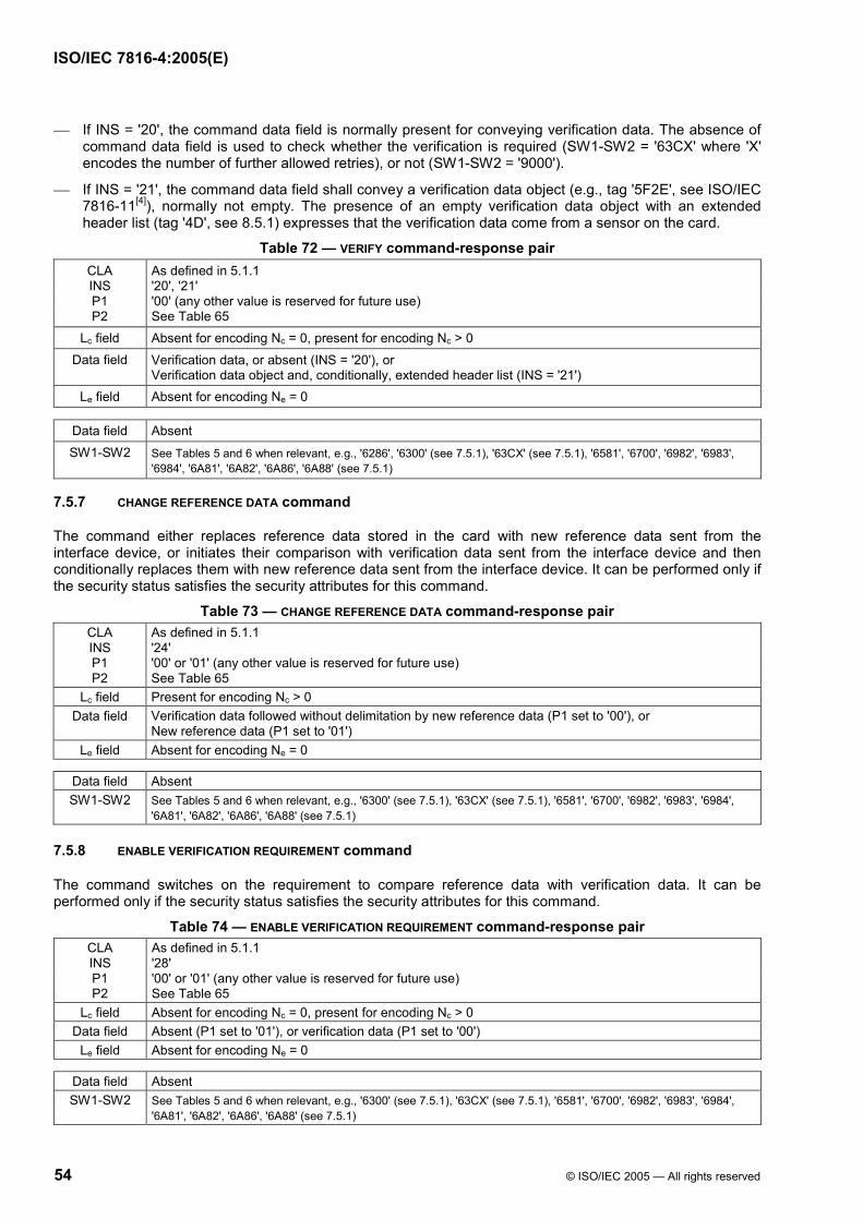
ISO/IEC 7816-4:2005(E)
54 © ISO/IEC 2005 — All rights reserved
If INS = '20', the command data field is normally present for conveying verification data. The absence of command data field is used to check whether the verification is required (SW1-SW2 = '63CX' where 'X' encodes the number of further allowed retries), or not (SW1-SW2 = '9000').
If INS = '21', the command data field shall convey a verification data object (e.g., tag '5F2E', see ISO/IEC 7816-11[4]), normally not empty. The presence of an empty verification data object with an extended header list (tag '4D', see 8.5.1) expresses that the verification data come from a sensor on the card.
Table 72 — VERIFY command-response pair CLA As defined in 5.1.1 INS '20', '21' P1 '00' (any other value is reserved for future use) P2 See Table 65
Lc field Absent for encoding Nc = 0, present for encoding Nc > 0 Data field Verification data, or absent (INS = '20'), or
Verification data object and, conditionally, extended header list (INS = '21') Le field Absent for encoding Ne = 0
Data field Absent SW1-SW2 See Tables 5 and 6 when relevant, e.g., '6286', '6300' (see 7.5.1), '63CX' (see 7.5.1), '6581', '6700', '6982', '6983',
'6984', '6A81', '6A82', '6A86', '6A88' (see 7.5.1)
7.5.7 CHANGE REFERENCE DATA command
The command either replaces reference data stored in the card with new reference data sent from the interface device, or initiates their comparison with verification data sent from the interface device and then conditionally replaces them with new reference data sent from the interface device. It can be performed only if the security status satisfies the security attributes for this command.
Table 73 — CHANGE REFERENCE DATA command-response pair CLA As defined in 5.1.1 INS '24' P1 '00' or '01' (any other value is reserved for future use) P2 See Table 65
Lc field Present for encoding Nc > 0 Data field Verification data followed without delimitation by new reference data (P1 set to '00'), or
New reference data (P1 set to '01') Le field Absent for encoding Ne = 0
Data field Absent SW1-SW2 See Tables 5 and 6 when relevant, e.g., '6300' (see 7.5.1), '63CX' (see 7.5.1), '6581', '6700', '6982', '6983', '6984',
'6A81', '6A82', '6A86', '6A88' (see 7.5.1)
7.5.8 ENABLE VERIFICATION REQUIREMENT command
The command switches on the requirement to compare reference data with verification data. It can be performed only if the security status satisfies the security attributes for this command.
Table 74 — ENABLE VERIFICATION REQUIREMENT command-response pair CLA As defined in 5.1.1 INS '28' P1 '00' or '01' (any other value is reserved for future use) P2 See Table 65
Lc field Absent for encoding Nc = 0, present for encoding Nc > 0 Data field Absent (P1 set to '01'), or verification data (P1 set to '00')
Le field Absent for encoding Ne = 0
Data field Absent SW1-SW2 See Tables 5 and 6 when relevant, e.g., '6300' (see 7.5.1), '63CX' (see 7.5.1), '6581', '6700', '6982', '6983', '6984',
'6A81', '6A82', '6A86', '6A88' (see 7.5.1)

ISO/IEC 7816-4:2005(E)
© ISO/IEC 2005 — All rights reserved 55
7.5.9 DISABLE VERIFICATION REQUIREMENT command
The command switches off the requirement to compare reference data with verification data, and possibly switches on the requirement to compare other reference data with verification data. It can be performed only if the security status satisfies the security attributes for this command.
Table 75 — DISABLE VERIFICATION REQUIREMENT command-response pair CLA As defined in 5.1.1 INS '26' P1 '00', '01' or 100xxxxx where xxxxx is a reference data number (any other value is reserved for future use)P2 See Table 65
Lc field Absent for encoding Nc = 0, present for encoding Nc > 0 Data field Absent (P1 set to '01'), or verification data (P1 set to '00' or 100x xxxx)
Le field Absent for encoding Ne = 0
Data field Absent SW1-SW2 See Tables 5 and 6 when relevant, e.g., '6300' (see 7.5.1), '63CX' (see 7.5.1), '6581', '6700', '6982', '6983', '6984',
'6A81', '6A82', '6A86', '6A88' (see 7.5.1) 7.5.10 RESET RETRY COUNTER command
The command either resets the reference data retry counter to its initial value, or changes reference data on completion of a reset of the reference data retry counter to its initial value. It can be performed only if the security status satisfies the security attributes for this command.
Table 76 — RESET RETRY COUNTER command-response pair CLA As defined in 5.1.1 INS '2C' P1 '00', '01', '02' or '03' (any other value is reserved for future use) P2 See Table 65
Lc field Absent for encoding Nc = 0, present for encoding Nc > 0 Data field Absent (P1 set to '03'), or
Resetting code followed without delimitation by new reference data (P1 set to '00'), or Resetting code (P1 set to '01'), or New reference data (P1 set to '02')
Le field Absent for encoding Ne = 0
Data field Absent SW1-SW2 See Tables 5 and 6 when relevant, e.g., '6300' (see 7.5.1), '63CX' (see 7.5.1), '6581', '6700', '6982', '6983', '6984',
'6A81', '6A82', '6A86', '6A88' (see 7.5.1)
7.5.11 MANAGE SECURITY ENVIRONMENT command
The command prepares secure messaging (see 6) and security commands (e.g., EXTERNAL, INTERNAL and GENERAL AUTHENTICATE, see also PERFORM SECURITY OPERATION in ISO/IEC 7816-8[4]). The command supports the following functions: SET, i.e., setting or replacing one component of the current SE; STORE, i.e., saving the current SE under the SEID byte in P2; RESTORE, i.e., replacing the current SE by a SE stored in the card and identified by the SEID byte in P2; ERASE, i.e., erasing a SE stored in the card and identified by the SEID byte in P2.

ISO/IEC 7816-4:2005(E)
56 © ISO/IEC 2005 — All rights reserved
Table 77 — MANAGE SECURITY ENVIRONMENT command-response pair CLA As defined in 5.1.1 INS '22' P1 See Table 78 P2 See Table 79
Lc field Absent for encoding Nc = 0, present for encoding Nc > 0 Data field Absent (STORE, RESTORE and ERASE), or concatenation of control reference data objects (SET)
Le field Absent for encoding Ne = 0
Data field Absent SW1-SW2 See Tables 5 and 6 when relevant, e.g., '6600', '6987', '6988, '6A88' (see 7.5.1)
Table 78 — P1 b8 b7 b6 b5 b4 b3 b2 b1 Meaning - - - 1 - - - - Secure messaging in command data field - - 1 - - - - - Secure messaging in response data field - 1 - - - - - - Computation, decipherment, internal authentication and key agreement 1 - - - - - - - Verification, encipherment, external authentication and key agreement - - - - 0 0 0 1 SET 1 1 1 1 0 0 1 0 STORE 1 1 1 1 0 0 1 1 RESTORE 1 1 1 1 0 1 0 0 ERASE
Any other value is reserved for future use by ISO/IEC JTC 1/SC 17.
Table 79 — P2 Value Meaning 'XX' SEID byte in the cases of STORE, RESTORE and ERASE (set to '00' in the case of GET SE)
Tag of the control reference template present in the command data field in the cases of SET, or GET CRT 'A4' — Control reference template for authentication (AT) 'A6' — Control reference template for key agreement (KAT) 'AA' — Control reference template for hash-code (HT) 'B4' — Control reference template for cryptographic checksum (CCT) 'B6' — Control reference template for digital signature (DST) 'B8' — Control reference template for confidentiality (CT)
Any other value is reserved for future use by ISO/IEC JTC 1/SC 17.
KEY DERIVATION function — The usage of a master key concept may require the derivation of a key in the card containing the master key. Table 80 shows the usage of the MANAGE SECURITY ENVIRONMENT command for deriving a key. It is assumed that the master key and the algorithm are implicitly selected in the card (otherwise, the MANAGE SECURITY ENVIRONMENT command can additionally select a key and an algorithm).
NOTE Depending on the algorithm reference, the data for deriving a key from a master key may be part of the input data of the subsequent command (e.g., EXTERNAL AUTHENTICATE). In this case the usage of the MANAGE SECURITY ENVIRONMENT command for deriving the key is not necessary.
Table 80 — Command-response pair for KEY DERIVATION function CLA As defined in 5.1.1 INS '22' P1 'X1' (SET, see Table 78) P2 CRT tag (e.g., 'A4' if an EXTERNAL AUTHENTICATE follows, or 'B4' if a VERIFY CRYPTOGRAPHIC CHECKSUM follows)
Lc field Present for encoding Nc > 0 Data field {'94' - L - Data for deriving a key (mandatory)}; SM data objects may be present
Le field Absent for encoding Ne = 0 Data field Absent SW1-SW2 See Tables 5 and 6 when relevant, e.g., '6600', '6987', '6988, '6A88' (reference data not found)

ISO/IEC 7816-4:2005(E)
© ISO/IEC 2005 — All rights reserved 57
7.6 Transmission handling
7.6.1 GET RESPONSE command
The command transmits [part of] response APDUs that otherwise could not be transmitted by the available transmission protocol. See examples in ISO/IEC 7816-3.
If the Le field contains only bytes set to '00', then all the available bytes should be returned within the limit of 256 for a short Le field, or 65 536 for an extended Le field.
Table 81 — GET RESPONSE command-response pair CLA As defined in 5.1.1 INS 'C0'
P1-P2 '0000' (any other value is reserved for future use) Lc field Absent for encoding Nc = 0
Data field Absent Le field Present for encoding Ne > 0
Data field Absent in any error case, or [Part of] a response APDU according to Ne SW1-SW2 See Tables 5 and 6 when relevant, e.g., '61XX' ('XX' encodes the number of extra bytes still available by a
subsequent GET RESPONSE), '6281', '6700', '6A81', '6A82', '6A86', '6CXX'
7.6.2 ENVELOPE command
The command transmits [part of] either a command APDU or a BER-TLV data object that otherwise could not be transmitted by the available transmission protocol. See examples in ISO/IEC 7816-3.
NOTE Annex B shows the usage of the ENVELOPE command for secure messaging.
Table 82 — ENVELOPE command-response pair CLA As defined in 5.1.1 INS 'C2', 'C3'
P1-P2 '0000' (any other value is reserved for future use) Lc field Present for encoding Nc > 0
Data field [Part of] a command APDU (INS = 'C2'), or [part of] a BER-TLV data object (INS = 'C3') Le field Absent for encoding Ne = 0, present for encoding Ne > 0
Data field [Part of] a response APDU (INS = 'C2'), or absent SW1-SW2 See Tables 5 and 6 when relevant, e.g., '6700'
8 Application-independent card services
This clause specifies application-independent card services, referred to as “card services”.
1) Card identification
2) Application identification and selection
3) Selection by path
4) Data retrieval
5) Data element retrieval
6) Card-originated byte strings

ISO/IEC 7816-4:2005(E)
58 © ISO/IEC 2005 — All rights reserved
The purpose of card services is to provide interchange mechanisms between a card and an interface device knowing nothing about each other except that they both comply with this document. Card services result from any combination of historical bytes (see 8.1.1), the contents of EF.DIR and EF.ATR (see 8.2.1.1) and sequences of commands. Unless otherwise specified, every command APDU uses CLA set to '00', i.e., no command chaining, no secure messaging and the basic logical channel.
There is no need for an application to comply with this clause once it has been identified and selected in the card. An application may use other mechanisms compatible with this document for achieving similar functions. Therefore such solutions may not guarantee interchange.
8.1 Card identification
This service allows the interface device to identify the card and to deal with it. The historical bytes (see 8.1.1) provide a generic support to card identification. The card provides information to the outside world on its logical content directly, e.g., through the card service data byte (see 8.1.1.2.3), and / or indirectly, e.g., through the initial access data (see 8.1.1.2.4) indicating an access to a file implicitly selected immediately after the answer to reset and a possible protocol and parameters selection. Consequently, the data available at this point, i.e., the initial data string (see 8.1.2), may not be subsequently retrievable.
8.1.1 Historical bytes
8.1.1.1 Purpose and general structure
The historical bytes indicate operating characteristics of the card. When a card answers to reset, the Answer-to-Reset may contain historical bytes (see ISO/IEC 7816-3). When the physical interface does not allow a card to answer to reset, e.g., a universal serial bus or an
access by radio frequency, a GET DATA command (see 7.4.2) may retrieve historical bytes (tag '5F52').
The first historical byte is the “category indicator byte”. If the category indicator byte is set to '00', '10' or '8X', then Table 83 summarizes the format of the historical bytes. Any other value indicates a proprietary format.
Table 83 — Category indicator byte Value Meaning
'00' A status indicator shall be present as the last three historical bytes (see 8.1.1.3) '10' See 8.1.1.4 '80' A status indicator may be present in a COMPACT-TLV data object (one, two or three bytes, see 8.1.1.3)
'81' to '8F' Reserved for future use Any other value indicates a proprietary format.
If the first historical byte is set to '00', then the remaining historical bytes consist of optional consecutive COMPACT-TLV data objects followed by a mandatory status indicator (the last three bytes, not in TLV).
If the first historical byte is set to '80', then the remaining historical bytes consist of optional consecutive COMPACT-TLV data objects; the last data object may carry a status indicator of one, two or three bytes.
Any interindustry BER-TLV data object consisting of a tag field set to '4X', a length field set to '0Y' and a value field of Y bytes can be converted into a COMPACT-TLV data object consisting of a byte set to 'XY' called “compact header” and a value field of Y bytes.
Any interindustry data element defined hereafter may be present in EF.ATR (see 8.2.1.1). If present in EF.ATR, it shall appear in a BER-TLV data object, i.e., a tag field set to '4X', a length field set to '0Y' and a value field of Y bytes.
8.1.1.2 Optional data elements
8.1.1.2.1 Country or issuer indicator
Referenced by a compact header set to either '1Y' or '2Y', this interindustry data element is a country or issuer indicator (see also tags '41' and '42' in Table 9). Table 84 shows the country or issuer indicator.
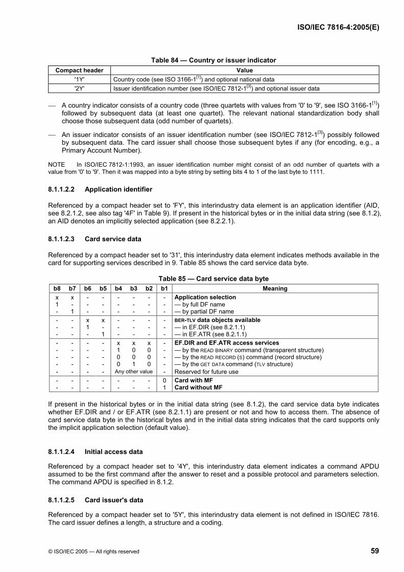
ISO/IEC 7816-4:2005(E)
© ISO/IEC 2005 — All rights reserved 59
Table 84 — Country or issuer indicator Compact header Value
'1Y' Country code (see ISO 3166-1[1]) and optional national data '2Y' Issuer identification number (see ISO/IEC 7812-1[3]) and optional issuer data
A country indicator consists of a country code (three quartets with values from '0' to '9', see ISO 3166-1[1])
followed by subsequent data (at least one quartet). The relevant national standardization body shall choose those subsequent data (odd number of quartets).
An issuer indicator consists of an issuer identification number (see ISO/IEC 7812-1[3]) possibly followed by subsequent data. The card issuer shall choose those subsequent bytes if any (for encoding, e.g., a Primary Account Number).
NOTE In ISO/IEC 7812-1:1993, an issuer identification number might consist of an odd number of quartets with a value from '0' to '9'. Then it was mapped into a byte string by setting bits 4 to 1 of the last byte to 1111.
8.1.1.2.2 Application identifier
Referenced by a compact header set to 'FY', this interindustry data element is an application identifier (AID, see 8.2.1.2, see also tag '4F' in Table 9). If present in the historical bytes or in the initial data string (see 8.1.2), an AID denotes an implicitly selected application (see 8.2.2.1).
8.1.1.2.3 Card service data
Referenced by a compact header set to '31', this interindustry data element indicates methods available in the card for supporting services described in 9. Table 85 shows the card service data byte.
Table 85 — Card service data byte b8 b7 b6 b5 b4 b3 b2 b1 Meaning x x - - - - - - Application selection 1 - - - - - - - — by full DF name - 1 - - - - - - — by partial DF name - - x x - - - - BER-TLV data objects available - - 1 - - - - - — in EF.DIR (see 8.2.1.1) - - - 1 - - - - — in EF.ATR (see 8.2.1.1) - - - - x x x - EF.DIR and EF.ATR access services - - - - 1 0 0 - — by the READ BINARY command (transparent structure) - - - - 0 0 0 - — by the READ RECORD (S) command (record structure) - - - - 0 1 0 - — by the GET DATA command (TLV structure) - - - - Any other value - Reserved for future use - - - - - - - 0 Card with MF - - - - - - - 1 Card without MF
If present in the historical bytes or in the initial data string (see 8.1.2), the card service data byte indicates whether EF.DIR and / or EF.ATR (see 8.2.1.1) are present or not and how to access them. The absence of card service data byte in the historical bytes and in the initial data string indicates that the card supports only the implicit application selection (default value).
8.1.1.2.4 Initial access data
Referenced by a compact header set to '4Y', this interindustry data element indicates a command APDU assumed to be the first command after the answer to reset and a possible protocol and parameters selection. The command APDU is specified in 8.1.2.
8.1.1.2.5 Card issuer's data
Referenced by a compact header set to '5Y', this interindustry data element is not defined in ISO/IEC 7816. The card issuer defines a length, a structure and a coding.

ISO/IEC 7816-4:2005(E)
60 © ISO/IEC 2005 — All rights reserved
8.1.1.2.6 Pre-issuing data
Referenced by a compact header set to '6Y', this interindustry data element is not defined in ISO/IEC 7816. The card manufacturer defines a length, a structure and a coding for a card manufacturer, an integrated circuit name, an integrated circuit manufacturer, a ROM mask version, an operating system version, etc. This interindustry data element may contain an integrated circuit manufacturer identifier (see ISO/IEC 7816-6).
8.1.1.2.7 Card capabilities
Referenced by a compact header set to '71', '72' or '73', this interindustry data element consists of up to three software function tables: either the first table, or the first two tables, or the three tables. The first software function table indicates selection methods supported by the card. The second software function table is the “data coding byte”. The data coding byte may also be present
as the second byte in the file control parameter referenced by tag '82' (see Table 12). The third software function table indicates the ability to chain commands, to handle extended Lc and Le
fields and to manage logical channels.
Table 86 — First software function table (selection methods) b8 b7 b6 b5 b4 b3 b2 b1 Meaning x x x x x - - - DF selection (see 5.3.1) 1 - - - - - - - — by full DF name - 1 - - - - - - — by partial DF name - - 1 - - - - - — by path - - - 1 - - - - — by file identifier - - - - 1 - - - Implicit DF selection - - - - - 1 - - Short EF identifier supported - - - - - - 1 - Record number supported - - - - - - - 1 Record identifier supported
Table 87 — Second software function table (data coding byte) b8 b7 b6 b5 b4 b3 b2 b1 Meaning 1 - - - - - - - EFs of TLV structure supported - x x - - - - - Behaviour of write functions - 0 0 - - - - - — One-time write - 0 1 - - - - - — Proprietary - 1 0 - - - - - — Write OR - 1 1 - - - - - — Write AND - - - - x x x x Data unit size in quartets (from one to 32 768 quartets, i.e., 16 384 bytes)
(power of 2, e.g., 0001 = 2 quartets = one byte, default value) - - - x - - - - Value 'FF' for the first byte of BER-TLV tag fields (see 5.2.2.1) - - - 0 - - - - — Invalid (used for padding, default value) - - - 1 - - - - — Valid (long private tags, constructed encoding)
Table 88 — Third software function table (command chaining, length fields and logical channels) b8 b7 b6 b5 b4 b3 b2 b1 Meaning 1 - - - - - - - Command chaining (see 5.1.1.1) - 1 - - - - - - Extended Lc and Le fields (see 5.1) - - - x x - - - Logical channel number assignment (see 7.1.2) - - - 1 - - - — by the card - - - 1 - - - — by the interface device - - - 0 0 - - - No logical channel - - - - - y z t Maximum number of logical channels (see 5.1.1 and 5.1.1.2)
— y, z and t not all set to 1 means 4y+2z+t+1, i.e., from one to seven — y = z = t = 1 means eight or more
- - x - - - - - RFU
8.1.1.3 Status indicator
If the category indicator byte is set to '00', then the last three historical bytes shall be a status indicator, namely a card life cycle status byte denoted LCS followed by two processing status bytes denoted SW1-SW2.

ISO/IEC 7816-4:2005(E)
© ISO/IEC 2005 — All rights reserved 61
If the category indicator byte is set to '80', then an interindustry data element referenced by a compact header set to '81', '82' or '83' may be present as a status indicator on one, two or three bytes (any other length is reserved for ISO/IEC JTC 1/SC 17) at the end of the historical bytes. If the length is one, then the data element is a card life cycle status byte denoted LCS. If the length is two, then the data element is two processing status bytes denoted SW1-SW2. If the length is three, then the data element is LCS followed by SW1-SW2.
LCS shall be interpreted according to 5.3.3.2 and Table 13; the value '00' indicates that the status is not reported. SW1-SW2 shall be interpreted according to 5.1.3 and Tables 5 and 6; the value '0000' indicates that the status is not reported.
8.1.1.4 DIR data reference
If the category indicator byte is set to '10', then the subsequent byte is the DIR data reference. The coding and meaning of this byte are outside the scope of this document.
8.1.2 Initial data string recovery
Referenced by a compact header set to '4Y' in the historical bytes (see 8.1.1.2.4) or by tag '44' in EF.ATR (see 8.2.1.1), the interindustry data element called “initial access data” indicates a command APDU. If the length is one, then the command APDU is a READ BINARY command (see 7.2.3) as follows: CLA INS
P1 P2 set to '00B0 0000' and a Le field set to the first and only byte of initial access data. If the length is two, then the first byte of initial access data indicates the structure (bit 8) and the short
identifier (bits 5 to 1) of the EF to read, according to Table 89. • If bit 8 of the first byte is set to 1, then the command APDU is a READ BINARY command (see 7.2.3) as
follows: CLA INS set to '00B0', P1 set to the first byte of initial access data, P2 set to '00' and a Le field set to the second byte of initial access data.
• If bit 8 of the first byte is set to 0, then the command APDU is a READ RECORD (S) command (see 7.3.3) as follows: CLA INS P1 set to '00B201', P2 consisting of bits 8 to 4 set to bits 5 to 1 of the first byte of initial access data (a short EF identifier) and bits 3 to 1 set to 110, and a Le field set to the second byte of initial access data.
Table 89 — First byte of initial access data when the length is two b8 b7 b6 b5 b4 b3 b2 b1 Meaning x - - - - - - - EF structure 0 - - - - - - - Record structure 1 - - - - - - - Transparent structure - - - x x x x x Short EF identifier - x x - - - - - x00x xxxx (any other value is reserved for future use)
If the length is five or more, then the command APDU consists of the Y bytes of initial access data.
The command APDU shall be submitted to the card. If the process is completed, then the response data field is a string of interindustry data objects every application might be interested in, called the “initial data string”.
8.2 Application identification and selection
This service allows the interface device to know what application is active in the card, if any, as well as how to identify and select any application supported by the card.

ISO/IEC 7816-4:2005(E)
62 © ISO/IEC 2005 — All rights reserved
8.2.1 Application identification
8.2.1.1 EF.DIR and EF.ATR
Two specific EFs provide a generic support to application identification and selection, namely EF.DIR and EF.ATR. They contain a set of BER-TLV data objects. In these EFs, erased or modified BER-TLV data objects may induce padding before, between and after data objects (see 5.2.2.1).
EF.DIR — This EF indicates a list of applications supported by the card. It contains a set of application templates and / or application identifier data objects, in any order. It determines which commands shall be performed in order to select the indicated applications.
EF.DIR shall have the MF as parent file: the path '3F002F00' references EF.DIR. At MF level, the short EF identifier 30, i.e., 11110 in binary, references EF.DIR if present.
EF.ATR — This EF indicates operating characteristics of the card. It contains a set of interindustry data objects which cannot be nested in EF.DIR, either because not relevant to application selection, or because there is no EF.DIR.
EF.ATR shall have the MF as parent file: the path '3F002F01' references EF.ATR.
8.2.1.2 Application identifier
Referenced by a compact header set to 'FY' in the historical bytes (see 8.1.1), or by tag '4F' in the initial data string (see 8.1.2), in EF.ATR, in EF.DIR and in the management data of any DF (see 5.3.3), this interindustry data element identifies an application.
An application identifier (AID) consists of up to sixteen bytes. Bits 8 to 5 of the first byte indicate a category according to Table 90.
Table 90 — Categories of application identifiers Value Category Meaning
'0' to '9' - Reserved for backward compatibility with ISO/IEC 7812-1[3] (see annex D) 'A' International International registration of application providers according to ISO/IEC 7816-5[4]
'B', 'C' - Reserved for future use by ISO/IEC JTC 1/SC 17 'D' National National (ISO 3166-1[1]) registration of application providers according to ISO/IEC 7816-5[4] 'E' Standard Identification of a standard by an object identifier according to ISO/IEC 8825-1 'F' Proprietary No registration of application providers
Figure 7 shows an international AID. It consists of a registered application provider identifier (international RID) on five bytes and optionally, a proprietary application identifier extension (PIX) on up to eleven bytes.
The international RID shall uniquely identify an application provider (see ISO/IEC 7816-5[4]). • Bits 8 to 5 of the first byte shall be set to 1010, i.e., the first quartet shall be set to 'A'. • Each one of the subsequent nine quartets shall be set from '0' to '9'.
The extension has a free encoding. It allows the application provider to identify its different applications.
Registered application provider identifier (International RID, five bytes, first byte set to 'AX')
Proprietary application identifier extension (PIX, up to eleven bytes)
Figure 7 — International AID
Figure 8 shows a national AID. It consists of a registered application provider identifier (national RID) on five bytes and optionally, a proprietary application identifier extension (PIX) on up to eleven bytes.
The national RID shall uniquely identify an application provider (see ISO/IEC 7816-5[4]). • Bits 8 to 5 of the first byte shall be set to 1101, i.e., the first quartet shall be set to 'D'.

ISO/IEC 7816-4:2005(E)
© ISO/IEC 2005 — All rights reserved 63
• The subsequent three quartets (from '0' to '9') shall form a country code (see ISO 3166-1[1]). • The recommended value of each one of the last six quartets is from '0' to '9'.
The extension has a free encoding. It allows the application provider to identify its different applications.
Registered application provider identifier (National RID, five bytes, first byte set to 'DX')
Proprietary application identifier extension (PIX, up to eleven bytes)
Figure 8 — National AID
Figure 9 shows a standard AID. It consists of up to sixteen bytes. The first byte shall be set to 1110 1000, i.e., to 'E8'. The values 'E0' to 'E7' and 'E9' to 'EF' are reserved for future use by ISO/IECJTC 1/SC 17. An object identifier (see ISO/IEC 8825-1) shall follow for identifying a standard specifying an application (see examples in annex A, e.g., ISO/IEC 7816-12[4], personal verification through biometric methods, ISO/IEC 7816-15[4], cryptographic information application). An application identifier extension (specified according to the identified standard) may follow for identifying different implementations.
'E8' Object identifier (see annex A) Application-specific application identifier extension
Figure 9 — Standard AID
Figure 10 shows a proprietary AID. It consists of up to sixteen bytes. Bits 8 to 5 of the first byte shall be set to 1111, i.e., to 'F'. In the proprietary category, as application providers are not registered, different application providers may use the same AID.
Proprietary application identifier (Proprietary AID, up to sixteen bytes, first byte set to 'FX')
Figure 10 — Proprietary AID
8.2.1.3 Application template
Referenced by tag '61', this interindustry template may be present in EF.ATR (see 8.2.1.1), in EF.DIR (see 8.2.1.1) and in the management data of any DF (see 5.3.3).
Such a template shall contain one and only one application identifier. If several application identifiers are valid names for the same DF, then each one should be present in a different application template.
Such a template may optionally contain other interindustry data objects relating to the application as listed in Table 91 and defined hereafter.
Table 91 — Interindustry data objects for application identification and selection Tag Value '4F' Application identifier '50' Application label '51' File reference '52' Command APDU
'53', '73' Discretionary data, discretionary template '5F50' Uniform resource locator (see IETF RFC 1738[19] and IETF RFC 2396[20])
'61' Set of application-related data objects 8.2.1.4 Other interindustry data elements
The following interindustry data elements provide a generic support to application identification and selection.
Application label — Referenced by tag '50', this interindustry data element is not defined in ISO/IEC 7816. The application provider defines it for use at the man-machine interface, e.g., a trademark to display.
File reference — Referenced by tag '51', this interindustry data element is defined in 5.3.1.2.
ISO/IEC 7816-4:2005(E)
64 © ISO/IEC 2005 — All rights reserved
Discretionary data (or template) — Referenced by tag '53' (or '73'), this interindustry data element (or template) consists of relevant data elements (or nests data objects) defined by the application provider.
Uniform resource locator — Referenced by tag '5F50', this interindustry data element is a uniform resource locator (URL) as defined in IETF RFC 1738[19] and IETF RFC 2396[20]. It points to part of the software required in the interface device to communicate with the application in the card.
8.2.2 Application selection
The card shall support at least one of the following application selection methods.
1) Implicit application selection
2) Application selection using an application identifier (AID, see 8.2.1.2) as DF name
3) Application selection using EF.DIR or EF.ATR
8.2.2.1 Implicit application selection
If an application is implicitly selected, then an application identifier should be present in the historical bytes (see 8.1.1) or in the initial data string (see 8.1.2). Such a presence denotes an implicitly selected application. If an application is implicitly selected with no application identifier in the historical bytes and in the initial data string, then an application identifier shall be present in EF.ATR (see 8.2.1.1). NOTE The implicit application selection is not recommended for multi-application cards.
8.2.2.2 Application selection using AID as DF name
In a multi-application environment, the card shall respond positively to a SELECT command specifying any application identifier (AID, see 8.2.1.2) as DF name. The interface device may thus explicitly select an application without previously checking the presence of the application in the card.
The card shall support a SELECT command with CLA INS P1 P2 set to '00A4 0400' for the first selection with a given and preferably complete application identifier in the command data field (see Table 39). Depending on whether the application is present or not, the card shall either complete or abort the command. In the case of a selection with a truncated DF name, the full DF name will be made available in the response data field as the file control parameter referenced by tag '84' (see Table 12). If the card supports selection with a truncated DF name, then the first selection is implementation-dependent, e.g., the first occurrence in a static list or the last activated application in a previous session. For the next selections, if any, the card shall support a SELECT command with CLA INS P1 P2 set to '00A4 0402' with the same command data field.
8.2.2.3 Application selection using EF.DIR or EF.ATR
For a multi-application interface device, the use of EF.DIR or EF.ATR may be more efficient than the previous method.
If an application identifier data object is not part of an application template and not accompanied by a file reference or command-to-perform data object, then the selection shall use AID as DF name.
If an application identifier data object is part of an application template together with a file reference data object (see 5.3.1.2), the value field of which consists of two or more bytes, then the selection by path shall be performed according to 8.3.
If an application identifier data object is part of an application template together with one or more command-to-perform data objects, then the application selection is done by the indicated command(s). If several, they shall be performed in the order presented in the template.
8.3 Selection by path
This service allows selection of EFs and un-named DFs by using a path, i.e., a file reference data element (see 5.3.1.2) consisting of three or more bytes.

ISO/IEC 7816-4:2005(E)
© ISO/IEC 2005 — All rights reserved 65
When the length is even, the path is either absolute or relative depending on whether the first two bytes are set to '3F00' or not. The last two bytes identify either a DF or an EF. • For a path to a DF, the selection should be done by one or more SELECT commands, with CLA INS P1
P2 Lc set to '00A4 0100 02'. • For a path to an EF, if the length is four or more, the selection should be done by one or more SELECT
commands, with CLA INS P1 P2 Lc set to '00A4 0100 02'. The last and possibly only selection uses the last two bytes of the path (an EF identifier) with CLA INS P1 P2 Lc set to '00A4 0200 02'.
When the length is odd, the path is qualified. It consists of either an absolute path without '3F00', or a relative path without the identifier of the current DF, followed by a byte to use as P1 in one or more SELECT commands. The value of P1 fixes the selection method. • If the value of P1 is '08' or '09', then the card shall support a SELECT command where the qualified
path specifies P1, Lc and the data field and where P2 is set to '00'. • In the other cases, the card shall support one or more SELECT commands with P1 set to the last byte
of the qualified path and P2 Lc set to '0002'. Every file along the path shall be selected sequentially.
8.4 Data retrieval
This service allows the interface device to read data stored in DFs and in EFs.
Once a DF has been selected, the contents relevant to interchange shall be the response data field to a GET DATA command (see 7.4.2) consisting of CLA INS set to '00CA' followed by P1-P2 set to '00FF' for BER-TLV data objects or to '02FF' for SIMPLE-TLV data objects, followed by a Le field containing only bytes set to '00'.
Once an EF has been selected, the contents relevant to interchange shall be the response data field to a READ command according to the file descriptor byte (see Table 14), if present in the control parameters.
The READ BINARY command (see 7.2.3) consists of CLA INS P1 P2 set to '00B0 0000' followed by a Le field containing only bytes set to '00'.
The READ RECORD (S) command (see 7.3.3) consists of CLA INS P1 P2 set to '00B2 0005' followed by a Le field containing only bytes set to '00'.
The GET DATA command (see 7.4.2) consists of CLA INS P1 P2 set to '00CA0000', followed by a Le field containing only bytes set to '00'.
In the absence of file descriptor byte in the control parameters of an EF, the command APDU is as follows.
If the first software function table (see Table 86) is present in the historical bytes or in EF.ATR and if it indicates the support of records, then the command APDU is a READ RECORD (S) as above.
Otherwise, i.e., when the table is absent in the historical bytes and in EF.ATR or if the table does not indicate the support of records, the command APDU is a READ BINARY as above.
8.5 Data element retrieval
This service allows the interface device to retrieve interindustry data elements used for interchange.
Before selecting an application, interindustry data objects should be retrieved directly or indirectly from the historical bytes (see 8.1.1), the initial data string (see 8.1.2), EF.ATR and EF.DIR (see 8.2.1.1), in that order, when present. These interindustry data objects shall be interpreted according to tag allocation schemes specified in 5.2.4.
Once an application is selected, interindustry data objects should be retrieved directly or indirectly from the management data (see 5.3.3) of the application DF and from specific EFs within the current DF. • Interindustry data objects may be present in the management data of any file (see 5.3.3).

ISO/IEC 7816-4:2005(E)
66 © ISO/IEC 2005 — All rights reserved
• Interindustry data elements may be retrieved in files referenced in a wrapper (see 8.5.1). Selection of an un-named DF or an EF known by its path is defined in 8.3. Reading data in a selected EF or DF is defined in 8.4.
• Interindustry data objects may be retrieved by GET DATA commands (see 7.4.2).
8.5.1 Indirect references to data elements
Element lists, tag lists, header lists, extended header lists and wrappers are interindustry data elements for indirectly referencing data elements in byte strings, e.g., contents of EFs supporting data units, data fields resulting from completing commands APDU (see 8.4), byte strings to sign (see ISO/IEC 7816-8[4]). Such a data element instructs the card how to interpret a command data field or to construct a response data field.
Element list — Referenced by tag '5F41', this interindustry data element denotes that the information to retrieve is not presented as data objects, but under application control. It shall be used only within the wrapper template. Its structure and the returned information are outside the scope of ISO/IEC 7816.
Tag list — Referenced by tag '5C', this interindustry data element is a concatenation of tag fields without delimitation. The byte string consists of the data objects, in the same order as the tag list.
Header list — Referenced by tag '5D', this interindustry data element is a concatenation of pairs of tag fields and length fields without delimitation. The byte string consists of the value fields, in the same order as the header list.
Extended header list — Referenced by tag '4D', this interindustry data element is a concatenation of pairs of tag fields and length fields without delimitation. The byte string is built as follows.
If a tag indicates a primitive encoding, then the pair of tag field and length field is replaced by data referenced by the tag. A zero length means that the complete data object / element is included in the byte string. A non-zero length means the maximum number of data bytes to be retrieved and consequently may require truncation.
A tag indicating a constructed encoding followed by a non-zero length, except '80', introduces a subsequent value field that is an extended header list. A tag indicating a constructed encoding followed by a zero length is ignored. A tag indicating a constructed encoding followed by '80' means that the complete constructed data object / complete template is included in the byte string.
The card shall ignore the elements of the extended header list that do not match the target structure.
The byte string consists of either
the value fields of the primitive data objects, possibly truncated according to the indicated lengths (Case 1), or
the primitive data objects, possibly truncated according to the indicated lengths, and nested in the respective template, the length of which complies with the BER-TLV rules (Case 2).
If present, the length '80' shall be replaced by the actual length. The complete constructed data object / complete template is included in the byte string.
The encoding of the byte string, namely, data objects or data elements, is indicated by an appropriate INS code or by an appropriate parameter of the command, e.g., either an appropriate encoding of the data field (either constructed for those containing data objects or primitive for those containing data elements), or tags 'AC' or 'BC' (see Table 31) used in the PERFORM SECURITY OPERATION command (see ISO/IEC 7816-8[4]).
EXAMPLES The following extended header list references the subsequent three primitive data objects.
Primitive T1 '00' Constructed tag T L = 4 Primitive T2 '00' Primitive T3 L = 5
Primitive T1 L1 Value1 Primitive T2 L2 Value2 Primitive T3 L3 (≥5) Value3

ISO/IEC 7816-4:2005(E)
© ISO/IEC 2005 — All rights reserved 67
Case 1: The byte string is a concatenation of data elements.
Value1 Value2 The first five bytes of value3
Case 2: The byte string is a concatenation of data objects.
T1 L1 Value1 T L = L2 + 9 T2 L2 Value2 T3 L = 5 The first five bytes of value3
Wrapper — Referenced by tag '63', this interindustry template shall consist of two data objects.
The first data object is either an element list (tag '5F41'), or a tag list (tag '5C'), or a header list (tag '5D'), or an extended header list (tag '4D').
The second data object is a reference to an EF (tag '51', see 5.3.1.2) and / or one or more commands-to-perform (tag '52'). If several, the commands APDU shall be processed in the presented order.
A data object referenced e.g., in a tag list, or a data element referenced e.g., in a header list, either shall be contained in the referenced file, or shall be (part of) the response data field to the last command APDU. Only one indirect reference shall be given in a wrapper. There may be more than one wrapper.
EXAMPLE The following wrapper template consists of a tag list and one command-to-perform.
{'63'-L-{'5C'-L-(Tag1-Tag2-Tag3)}-{'52'-L-Command APDU}}
8.6 Card-originated byte strings
This service allows the card to originate byte strings.
For clarity, this clause speaks of a query as [part of] a card-originated byte string and of a reply as [part of] a response sent by an entity in the outside world; for example, a complete set of queries may form a command APDU and a complete set of replies a response APDU, thus allowing communication service from card to interface device and also, from card to card, possibly through a network.
This clause specifies the following three features.
How the card shall use SW1-SW2 as a trigger indicating that the card wants to issue a byte string, for which the card possibly expects a response.
How the interface device shall use the GET DATA command (see 7.4.2) for retrieving a query from the card and the PUT DATA command (see 7.4.3) for transmitting a reply, if any, to the card.
How the byte strings shall be formatted.
8.6.1 Triggering by the card
SW1-SW2 set to '62XX' with the value of 'XX' from '02' to '80' means that the card has a query of 'XX' bytes that the interface device should retrieve and for which the card possibly expects a response.
SW1-SW2 set to '64XX' with the value of 'XX' from '02' to '80' means that the card aborted the command; a possible completion of the command is conditioned by the recovery of a query of 'XX' bytes, for which the card possibly expects a response.
If present in the historical bytes with a value such as above, SW1-SW2 shall be interpreted as above.
If a PUT DATA command (see 7.4.3) for transmitting a reply is aborted with SW1-SW2 set to '64XX', then
with '64XX' from '6402' to '6480', the card wants to send at least one more query of 'XX' bytes;
with '64XX' set to '6401', the card is expecting an immediate response.

ISO/IEC 7816-4:2005(E)
68 © ISO/IEC 2005 — All rights reserved
8.6.2 Queries and replies
For retrieving a query of 'XX' bytes available in the card, the interface device shall send a GET DATA command with P1-P2 set to '0000' and a Le field set to 'XX'. SW1-SW2 set to '62XX' with the value of 'XX' from '02' to '80' means that the interface device should
retrieve a further query of 'XX' bytes and concatenate it to the already retrieved query before processing the card-originated byte string in the outside world.
SW1-SW2 set to '9000' means that the card-originated byte string is complete; it may be processed in the outside world.
For transmitting a reply to the card, the interface device shall send a PUT DATA command with P1-P2 set to '0000'. If the response is too long for a single command, then several PUT DATA commands shall be chained (see 5.1.1.1). Each PUT DATA command transmits a reply and the concatenation of the replies is the response.
8.6.3 Formats
The value of the first byte of the card-originated byte string indicates a format as follows. If the first byte is set to 'FF', then the subsequent bytes shall encode an initial protocol identifier according
to ISO/IEC TR 9577[5]; the byte strings shall comply with the indicated protocol. Otherwise (i.e., when the first byte is not set to 'FF'), the card-originated byte string and the response
together shall form a command-response pair.
All conditions are relevant to the transmission protocol indicated by the card, except for the proper use of GET DATA command, PUT DATA command and status bytes SW1-SW2. This clause makes no assumption on the need for a response and on the entity responsible for the contents of the possible response.

ISO/IEC 7816-4:2005(E)
© ISO/IEC 2005 — All rights reserved 69
Annex A (informative)
Examples of object identifiers and tag allocation schemes
A.1 Object identifiers
For ISO standards, the first byte is '28', i.e., 40 in decimal (see ISO/IEC 8825-1). One or more series of bytes follow; bit 8 is set to 0 in the last byte of a series and to 1 in the previous bytes, if there is more than one byte. The concatenation of bits 7 to 1 of the bytes of a series encodes a number. Each number shall be encoded on the fewest possible bytes, that is, the value '80' is invalid for the first byte of a series. The first number is the number of the standard; the second number, if present, is the part in a multi-part standard.
As a first example, {iso(1) standard(0) ic-cards(7816)} references ISO/IEC 7816. 7816 is equal to '1E88', i.e., 0001 1110 1000 1000, i.e., two blocks of seven bits: 0111101 0001000. After insertion of the appropriate value of bit 8 in each byte, the encoding of the first series is therefore
1011 1101 0000 1000, equal to 'BD08'.
The data element '28 BD08' may be used in AIDs of standard category (see 8.2.1.2). AID = 'E8 28 BD08 0B XX … XX' (ISO/IEC 7816-11 specifies the application identifier extension 'XX … XX'). AID = 'E8 28 BD08 0F XX … XX' (ISO/IEC 7816-15 specifies the application identifier extension 'XX … XX').
As a second example, {iso(1) standard(0) e-auth(9798) part(5)} references ISO 9798-5[8]. The first series is obtained as follows. 9798 is equal to '2646', i.e., 0010 0110 0100 0110, i.e., two blocks of seven bits: 1001100 1000110. After insertion of the appropriate value of bit 8 in each byte, the encoding of the first series is therefore
11001100 01000110, equal to 'CC46'.
The data element '28 CC46 05 02' references the second mechanism in ISO/IEC 9798-5[8], i.e., GQ2. Such an identifier may be conveyed in a data object (tag '06', universal class, see ISO/IEC 8825-1).
DO = {'06 05 28 CC 46 05 02'}
As a third example, {iso(1) standard(0) mess(9992) part(2)} references ISO 9992-2[10]. The first series is obtained as follows. 9992 is equal to '2708', i.e., 0010 0111 0000 1000, i.e., two blocks of seven bits: 1001110 0001000. After insertion of the appropriate value of bit 8 in each byte, the encoding of the first series is therefore
1100 1110 0000 1000, equal to 'CE08'.
The data element is '28 CE08 02' (the second series is '02'). It may be conveyed in a data object. DO = {'06 04 28 CE 08 02'}
A.2 Tag allocation schemes
Example of default tag allocation scheme
DO1 = {'59 02 95 02'} DO2 = {'5F 24 03 97 03 31'}
DO1 (tag '59', card expiration date) encodes February 1995 as card expiration date (see ISO/IEC 7816-6).
DO2 (tag '5F24', application expiration date) encodes March 31st 1997 as application expiration date.

ISO/IEC 7816-4:2005(E)
70 © ISO/IEC 2005 — All rights reserved
Example of compatible tag allocation scheme
DO1 = {'78 06' {'06 04 28 CE 08 02'}} DO2 = {'5F 24 03 97 03 31'} DO3 = {'70 04' {'80 02 XX XX'}} DO4 = {'67 0A' {'5F 29 03 XX XX XX'} {'81 02 XX XX'}}
DO1 (tag '78', compatible tag allocation authority) indicates a compatible tag allocation scheme defined in ISO 9992-2[10] referenced by its object identifier. If DO1 appears either in the initial data string (see 8.1.2), or in EF.ATR (see 8.2.1.1), then the tag allocation authority is valid for the entire card. If DO1 appears in the management data of a DF (see 5.3.3), then the tag allocation authority is valid within that DF.
DO2 (tag '5F24', application expiration date) encodes March 31st 1997 as application expiration date.
DO3 (tag '70', interindustry template according to the included tag allocation authority) contains a data object, tag '80', defined in ISO 9992-2[10]; the meaning of tag '70' is also defined in ISO 9992-2[10].
DO4 (tag '67', authentication data template) contains the interchange profile data object, tag '5F29', and a data object, tag '81', defined in ISO 9992-2[10]; the meaning of tag '67' is defined in ISO/IEC 7816-6[4].
Another example of compatible tag allocation scheme
DO2 = {'5F 24 03 97 03 31'} DO3 = {'70 0C' {'06 04 28 CE 08 02'} {'80 04 XX XX XX XX'}} DO4 = {'67 06' {'5F 29 03 XX XX XX'}}
DO2 (tag '5F24', application expiration date) encodes March 31st 1997 as application expiration date.
DO3 (tag '70', interindustry template defined according to the included object identifier) contains a data object, tag '06', which specifies that the subsequent data object, tag '80', is defined in ISO 9992-2[10]. The meaning of tag '70' is also defined in ISO 9992-2[10].
DO4 (tag '67', interindustry authentication data template) contains the interchange profile data object, tag '5F29'. Note that it cannot contain data objects defined in ISO 9992-2[10], because of the choice not to transmit the interindustry data object with tag '78'.
Example of coexistent tag allocation scheme
DO1 = {'79 05' {'06 03 28 XX XX'}} DO2 = {'7E 06' {'5F 24 03 97 03 31'}} DO3 = {'70 06' {'XX XX XX XX XX XX'}}
DO1 (tag '79', coexistent tag allocation authority) indicates a coexistent tag allocation scheme defined in a standard referenced by an object identifier starting with '28', therefore an ISO standard. Mandatory in such a scheme, DO1 shall appear either in the initial data string (see 8.1.2) or in EF.ATR (see 8.2.1.1) if the tag allocation authority is valid for the
entire card, or in the management data of a DF (see 5.3.3) if the tag allocation authority is valid within that DF.
DO2 (tag '7E') is an interindustry template for nesting interindustry data objects. Note that the interindustry data object “application expiration date”, tag '5F24', is present, encoding March 31st 1997 as application expiration date.
DO3 (tag '70', interindustry template to be interpreted according to the tag allocation authority indicated in template '79') can only be interpreted according to the standard indicated in the object identifier.

ISO/IEC 7816-4:2005(E)
© ISO/IEC 2005 — All rights reserved 71
Annex B (informative)
Examples of secure messaging
B.1 Cryptographic checksum
This clause shows the use of secure messaging (see 6) and cryptographic checksums (see 6.2.3.1) for each of the four cases of command-response pairs defined in ISO/IEC 7816-3.
In the examples, the notation CLA* means the use of secure messaging in the data fields: in CLA (see 5.1.1), either bits 8, 7 and 6 set to 000 and bit 4 set to 1, or bits 8, 7 and 6 set to 011.
In the examples, the notation CLA** means that bits 8, 7 and 6 of CLA are set to 000 and bits 4 and 3 to 11, i.e., that the command header shall be included in the computation of a data element for authentication.
Alternately the header may be encapsulated in a data object with tag '89', i.e., a SM data object to be included in the computation of a data element for authentication.
In the examples, the notation T* means that bit 1 of the last byte of the tag field is set to 1 (an odd tag number), i.e., that the SM data object shall be included in the computation of a data element for authentication.
Case 1 — No command data, no response data
The unsecured command-response pair is as follows.
Command header Command body
CLA INS P1 P2 Absent
Response body Response trailer
Absent SW1-SW2
Case 1.a — Status not protected
The secured command APDU is as follows.
Command header Command body
CLA* INS P1 P2 {New Lc field} - {New data field (= T - L - Cryptographic checksum)}
If the length of the cryptographic checksum is four bytes, then the new Lc field is set to '06'.
New data field = One data object = {T - L - Cryptographic checksum}
Data covered by the cryptographic checksum (bit 3 of CLA* set to 1) = One block = {CLA** INS P1 P2 Padding}
The secured response APDU is as follows.
Response body Response trailer
Absent SW1-SW2

ISO/IEC 7816-4:2005(E)
72 © ISO/IEC 2005 — All rights reserved
Case 1.b — Status protected
The secured command APDU is as follows.
Command header Command body
CLA* INS P1 P2 {New Lc field} - {New data field (= T - L - Cryptographic checksum)} - {New Le field (= '00')}
New data field = One data object = {T - L- Cryptographic checksum}
Data covered by the cryptographic checksum (bit 3 of CLA* set to 1) = One block = {CLA** INS P1 P2 Padding}
The secured response APDU is as follows.
Response body Response trailer
New data field (={T* - L - SW1-SW2} - {T - L - Cryptographic checksum}) SW1-SW2
New data field = Two data objects = {T* - L - SW1-SW2} - {T - L - Cryptographic checksum}
Data covered by the cryptographic checksum = One block = {T* - L - SW1-SW2 - Padding}
Case 2 — No command data, response data
The unsecured command-response pair is as follows.
Command header Command body
CLA INS P1 P2 Le field
Response body Response trailer
Data field SW1-SW2
The secured command APDU is as follows.
Command header Command body
CLA* INS P1 P2 New Lc field - New data field - {New Le field (one or two bytes set to '00')}
New data field = Two data objects = {T* - L - Le} - {T - L - Cryptographic checksum}
Data covered by the cryptographic checksum = One block = {T* - L - Le - Padding} if bit 3 of CLA* set to 0 Two blocks = {CLA** INS P1 P2 Padding} - {T* - L - Le - Padding} if bit 3 of CLA* set to 1
The secured response APDU is as follows.
Response body Response trailer
New data field (={T* - L - Plain value} - {T* - L - SW1-SW2} - {T - L - Cryptographic checksum})
SW1-SW2
New data field = Three data objects = {T* - L - Plain value} - {T* - L - SW1-SW2} - {T - L - Cryptographic checksum}
Data covered by the cryptographic checksum = One or more blocks = {T* - L - Plain value - T* - L - SW1-SW2 - Padding}

ISO/IEC 7816-4:2005(E)
© ISO/IEC 2005 — All rights reserved 73
Case 3 — Command data, no response data
The unsecured command-response pair is as follows.
Command header Command body
CLA INS P1 P2 Lc field - Data field
Response body Response trailer
Absent SW1-SW2
Case 3.a — Status not protected
The secured command APDU is as follows.
Command header Command body
CLA* INS P1 P2 New Lc field - New data field
New data field = Two data objects = {T* - L - Plain value} - {T - L -Cryptographic checksum}
Data covered by the cryptographic checksum = One or more blocks = {T* - L - Plain value - Padding} if bit 3 of CLA* set to 0 Two or more blocks = {CLA** INS P1 P2 Padding} - {T* - L - Plain value - Padding} if bit 3 of CLA*
set to 1
The secured response APDU is as follows.
Response body Response trailer
Absent SW1-SW2
Case 3.b — Status protected
The secured command APDU is as follows.
Command header Command body
CLA* INS P1 P2 New Lc field - New data field - New Le field (= '00')
New data field = Two data objects = {T* - L - Plain value} - {T - L - Cryptographic checksum}
Data covered by the cryptographic checksum = One or more blocks = {T* - L - Plain value - Padding} if bit 3 of CLA* set to 0 Two or more blocks = {CLA** INS P1 P2 Padding} - {T* - L - Plain value - Padding} if bit 3 of CLA*
set to 1
The secured response APDU is as follows.
Response body Response trailer
New data field (= {T* - L - SW1-SW2} - {T - L - Cryptographic checksum}) SW1-SW2
New data field = Two data objects = {T* - L - SW1-SW2} - {T - L - Cryptographic checksum}
Data covered by the cryptographic checksum = One block = {T* - L - SW1-SW2 - Padding}

ISO/IEC 7816-4:2005(E)
74 © ISO/IEC 2005 — All rights reserved
Case 4 — Command data, response data
The unsecured command-response pair is as follows.
Command header Command body
CLA INS P1 P2 Lc field - Data field - Le field
Response body Response trailer
Data field SW1-SW2
The secured command APDU is as follows.
Command header Command body
CLA* INS P1 P2 New Lc field - New data field - New Le field (one or two bytes set to '00')
New data field = Three data objects = {T* - L - Plain value} - {T* - L - Le} - {T - L - Cryptographic checksum}
Data covered by the cryptographic checksum = One or more blocks = {T* - L - Plain value - T* - L - Le - Padding} if bit 3 of CLA* set to 0 Two or more blocks = {CLA** INS P1 P2 Padding} - {T* - L - Plain value - T* - L - Le - Padding} if bit
3 of CLA* set to 1
The secured response APDU is as follows.
Response body Response trailer
New data field (={T* - L - Plain value} - {T* - L - SW1-SW2} - {T - L - Cryptographic checksum})
SW1-SW2
New data field = Three data objects = {T* - L - Plain value} - {T* - L - SW1-SW2} - {T - L - Cryptographic checksum}
Data covered by the cryptographic checksum = One or more blocks = {T* - L - Plain value - T* - L - SW1-SW2 - Padding}
B.2 Cryptograms
The use of cryptograms with and without padding (see 6.2.2) is shown in command and response data fields. Instead of the plain value data objects in the previous examples, data objects for confidentiality shall be used as follows.
Case a — Plain value not encoded in BER-TLV
Data field = {T - L - Padding-content indicator byte - Cryptogram}
Plain value conveyed by the cryptogram = One or more blocks = Plain value not encoded in BER-TLV, possibly padded according to the indicator byte
Case b — Plain value encoded in BER-TLV
Data field = {T - L - Cryptogram}
Plain value conveyed by the cryptogram = String of concealed bytes = BER-TLV data objects (padding depending on the algorithm and its mode of operation)

ISO/IEC 7816-4:2005(E)
© ISO/IEC 2005 — All rights reserved 75
B.3 Control references
The use of control references (see 6.3.1 and 6.3.2) is shown.
Command data field = {T - L - Control reference template}, where control reference template = {T - L - File reference} - {T - L - Key reference}
B.4 Response descriptor
The use of response descriptor (see 6.3.3) is shown.
Command data field = {T - L - Response descriptor} where response descriptor = {T (Plain value) - '00' - T (Cryptographic checksum) - '00'}
Response data field = {T - L - Plain value} - {T - L - Cryptographic checksum}
B.5 ENVELOPE command
The use of the ENVELOPE command (see 7.6.2) is shown.
Command data field = {T - L - Padding-content indicator byte - Cryptogram}
Plain value conveyed by the cryptogram = Command APDU (starting by CLA* INS P1 P2), padding according to the indicator byte
Response data field = {T - L - Padding-content indicator byte - Cryptogram}
Plain value conveyed by the cryptogram = Response APDU, padding according to the indicator byte
B.6 Synergy between secure messaging and security operations
For the purposes of this clause, the following symbols and abbreviated terms apply.
CC cryptographic checksum
CG cryptogram
CLA** CLA with SM indication (bits 8, 7 and 6 set to 000 and bits 4 and 3 set to 11)
DS digital signature
MSE manage security environment
PCI padding-content indicator byte
PSO perform security operation
SMC security module card
USC user smart card
The example explains how to use a security module card (SMC) that performs security operations for producing a secured command APDU to send to a user card (USC) and for processing the corresponding secured response APDU received thereon from the USC, i.e., for producing and processing data fields in SM format. The example illustrates the synergy between the two approaches: the atomic approach by security operations (see ISO/IEC 7816-8[4]) and the global approach by secure messaging (see 6).

ISO/IEC 7816-4:2005(E)
76 © ISO/IEC 2005 — All rights reserved
The example assumes that the USC and the SMC have completed a mutual authentication procedure, based e.g., on card verifiable certificates. The authentication procedure includes a key transport or key agreement mechanism so that after this procedure, two symmetric keys are available in the USC and in the SMC:
a symmetric session key for computing cryptographic checksums and
a symmetric session key for computing cryptograms.
The authentication procedure initialises one or more counters in the USC and the SMC. The example does not show the maintenance and the use of such counters by the USC and the SMC.
All the command-response pairs for the SMC are PSO commands, not using secure messaging, but using SM data objects (and the SM keys set by MSE commands).
All the command-response pairs for the USC use secure messaging and the command headers are included in the computation of cryptographic checksums, i.e., CLA is switched to CLA**.
Figure B.1 shows the general principles for producing a secured command APDU.
Figure B.1 — Producing a secured command APDU
Figure B.2 shows the general principles for processing a secured response APDU.
Figure B.2 — Processing a secured response APDU
Secured command APDU (sent to the USC)
CLA-INS-P1-P2
CLA switched to CLA**
Lc field Data field Le field
PSO ENCIPHER Command data
Unsecured command APDU
SMC Interface
CG(Command data) '9000'
PSO COMPUTE CC CLA**-INS-P1-P2 - Padding -'87'-L-PCI='01'- CG(Command data) -'97'-'01'- Le - Padding
CC '9000'
New Le field
'87'-L-PCI='01'-CG(Response data)-'99'-'02'-'9000'-'8E'-'04'-CC '9000'
Secured response APDU (received from the USC)
SMC Interface
PSO VERIFY CC '80'-L-{'87'-L-PCI='01'-CG(Response data)}-'99'-'02'-'9000'-'8E'-'04'-CC
'9000'
CLA**-INS-P1-P2 New Lc field '87'-L-PCI='01'-CG(Data)-'97'-'01'- Le -'8E'-'04'-CC
PSO DECIPHER CG(Response data)
Response data '9000'

ISO/IEC 7816-4:2005(E)
© ISO/IEC 2005 — All rights reserved 77
The following scenario explains the computation of a digital signature (DS) whereby the usage of the private signature key requires the successful presentation of a password. The scenario proceeds in three steps.
Step 1 — Password verification
1.1 Command to SMC: MSE SET <CT, {'83'-'01'-'81'}> --- The reference of the session key for computing cryptographic checksums is '81' in the example. SMC response: OK
1.2 Command to SMC: MSE SET <CCT, {'83'-'01'-'82'}> ---The reference of the session key for computing cryptograms is '82' in the example. SMC response: OK
1.3 Command to SMC: PSO ENCIPHER <Password> SMC response: <CG(Password)>
1.4 Command to SMC: PSO COMPUTE CC <CLA**-INS-P1-P2 - Padding - {'87'-L-PCI-CG(Password)} - {'97'-'01'-Le} - Padding> SMC response: <CC>
--- Now the interface device constructs the secured VERIFY command APDU.
1.5 Command to USC: VERIFY <{'87'-L-PCI='01'-CG(Password)} - {'97'-'01'-Le} - {'8E'-'04'-CC}> USC response: <{'99'-'02'-SW1-SW2} - {'8E'-'04'-CC}>
1.6 Command to SMC: PSO VERIFY CC <{'80'-'04'-('99'-'02'-SW1-SW2)} - {'8E'-'04'-CC}> SMC response: OK
Step 2 — Hash code computation
2.1 Command to SMC: PSO COMPUTE CC <CLA**-INS-P1-P2 - Padding - {'81'-L-({'90'-L-Intermediate Hash} - {'80'-L-Last block})} - {'97'-'01'-Le} - Padding> SMC response: <CC>
2.2 Command to USC: PSO HASH <{'81'-L1 (=4+L2+L3)-({'90'-L2- Intermediate Hash} - {'80'-L3-Last block})} - {'8E'-'04'-CC}> --- The USC stores the hash code as an internal result for computing the digital signature later on. USC response: <{'99'-'02'-SW1-SW2} - {'8E'-'04'-CC}>
2.3 Command to SMC: PSO VERIFY CC <{'80'-'04'-({'99'-'02'-SW1-SW2})} - {'8E'-'04'-CC}> SMC response: OK
Step 3 — Digital signature computation
3.1 Command to SMC: PSO COMPUTE CC <CLA**-INS-P1-P2 - Padding - {'97'-'01'-'00'}> SMC response: <CC>
3.2 Command to USC: PSO COMPUTE DS <{'97'-'01'-'00'} - {'8E'-'04'-CC}> USC response: <'81'-L-DS - '8E'-'04'-CC>
3.3 Command to SMC: PSO VERIFY CC <{'80'-L1 (=2+L2)-('81'-L2-DS)} - {'8E'-'04'-CC}> SMC response: OK

ISO/IEC 7816-4:2005(E)
78 © ISO/IEC 2005 — All rights reserved
Annex C (informative)
Examples of AUTHENTICATE functions by GENERAL AUTHENTICATE commands
C.1 Introduction
Two or more GENERAL AUTHENTICATE command-response pairs implement an AUTHENTICATE function. If chaining is used, then CLA is set to 0xx1 xxxx in the first command of the chain up to the penultimate
one and to 0xx0 xxxx in the last one: the other six bits shall remain constant within the chain (see 5.1.1.1). INS P1 P2 is set to either '86 00 00', or '87 00 00'. The value of the Lc field depends upon the data objects in the command data field. Depending upon
whether a response data field is expected or not, the Le field is either set to '00', or absent.
This annex illustrates data fields of GENERAL AUTHENTICATE commands implementing mechanisms such as specified in ISO/IEC 9798-5[8], i.e., mechanisms using zero-knowledge techniques. A verifier knows a public problem and a claimant knows a secret solution to the public problem. As a result of the zero-knowledge protocol, the verifier is convinced that the claimant knows a solution to
the public problem. Moreover, the solution remains secret.
NOTE ISO/IEC 9798-5[8] specifies two GQ techniques. Being given a public RSA key where the exponent v is prime such as 257 = 28+1, 65537 = 216+1 or 236+213+1, the GQ1 technique allows verifying an RSA signature without taking knowledge of its value, or alternately, proving knowledge of an RSA signature without revealing its value. As specified by the RSA signature standard in use (e.g., see ISO/IEC 14888-2[16]), a format mechanism converts the claimant's identification data (a template) into a public number G. The corresponding private number Q is the RSA signature of the identification data. The claimant and the verifier know the public RSA key. The GQ1 protocol proves that the claimant knows the RSA signature of his identification data. Being given a public modulus n, product of two prime factors, the GQ2 technique allows verifying the factors without taking knowledge of them, or alternately, proving knowledge of the factors without revealing them. The mechanism involves a security parameter k > 0 and the first m prime numbers, named the m basic numbers, such that k×m is from 8 to 36. Each public number is the square of a basic number: G = g2. The corresponding private number Q is a modular 2k+1-th root of G. If there is at least one basic number g such that the Jacobi symbol of g with respect to n is –1 and if n is congruent to 1 mod 4, then the GQ2 protocol proves that n is composite and that the claimant knows the factors.
The protocol typically exchanges three numbers, namely a witness, a challenge and a response. The claimant works in two steps: as a first step, the claimant privately selects a fresh random number and
converts it into a witness according to a “witness formula”; as a second step, having received a challenge, the claimant gets the response to the challenge from the fresh random number and the private number, according to a “response formula”, and then erases the fresh random number.
The verifier reconstructs a witness from the challenge and the response, according to a “verification formula”.
By definition, a triple consists of three numbers, namely, a witness, a challenge and a response, verifying the verification formula. Any entity may randomly produce triples in “public mode”, from any challenge and response. A judge or an observer cannot distinguish random triples produced in public mode, i.e., by an entity not knowing the secret, and random triples produced in “private mode”, i.e., by an entity knowing the secret.
This annex illustrates three AUTHENTICATE functions. INTERNAL AUTHENTICATE function — A verifier in the outside world authenticates a claimant in the card. EXTERNAL AUTHENTICATE function — A verifier in the card authenticates a claimant in the outside world. MUTUAL AUTHENTICATE function — Both entities authenticate each other.

ISO/IEC 7816-4:2005(E)
© ISO/IEC 2005 — All rights reserved 79
C.2 INTERNAL AUTHENTICATE function
If the first data field conveys a witness request, namely, either an empty witness ('80 00'), or an empty authentication code ('84 00'), then the function is INTERNAL AUTHENTICATE.
Basic protocol (two command-response pairs) Witness from the card
Command data field {'7C'-'02'-{'80'-'00'}} Response data field {'7C'-L1 (=2+L2)-{'80'-L2-Witness}}
Challenge from the outside world and response from the card Command data field {'7C'-L1 (=4+L2)-{'81'-L2-Challenge}-{'82'-'00'}} Response data field {'7C'-L1 (=2+L2)-{'82'-L2-Response}}
Committed challenge (two command-response pairs) Witness from the card
Command data field {'7C'-L1 (=4+L2)-{'83'-L2-Committed Challenge}-{'80'-'00'}} Response data field {'7C'-L1 (=2+L2)-{'80'-L2-Witness}}
NOTE The committed challenge ensures that the challenge and the witness are independently selected.
Challenge from the outside world and response from the card Command data field {'7C'-L1 (=4+L2)-{'81'-L2-Challenge}-{'82'-'00'}} Response data field {'7C'-L1 (=2+L2)-{'82'-L2-Response} if the challenge is correct
Absent if the challenge is incorrect
Extension to data field authentication (two command-response pairs) The card has hashed previously exchanged data fields: the result is a current hash-code. The card includes its witness data object for getting an authentication code and transmits it with tag '84'.
Witness from the card Command data field {'7C'-'04'-{'84'-'00'}} Response data field {'7C'-L1 (=2+L2)-{'84'-L2-Authentication code}}
Challenge from the outside world and response from the card Command data field {'7C'-L1 (=4+L2)-{'81'-L2-Challenge}-{'82'-'00'}} Response data field {'7C'-L1 (=2+L2)-{'82'-L2-Response}}
C.3 EXTERNAL AUTHENTICATE function
If the first data field conveys a challenge request, namely, either an empty challenge ('81 00'), or an empty committed challenge ('83 00'), then the function is EXTERNAL AUTHENTICATE.
Basic protocol (two command-response pairs) Witness from the outside world and challenge from the card
Command data field {'7C'-L1 (=4+L2)-{'80'-L2-Witness}-{'81'-'00'}} Response data field {'7C'-L1 (=2+L2)-{'81'-L2-Challenge}}

ISO/IEC 7816-4:2005(E)
80 © ISO/IEC 2005 — All rights reserved
Response from the outside world and verification by the card Command data field {'7C'-L1 (=2+L2)-{'82'-L2-Response}} Response data field Absent
Committed challenge (three command-response pairs) Committed challenge from the card
Command data field {'7C'-'02'-{'83'-'00'}} Response data field {'7C'-L1 (=4+L2)-{'83'-L2-Committed challenge}-{'80'-'00'}}
Witness from the outside world and challenge from the card Command data field {'7C'-L1 (=4+L2)-{'80'-L2-Witness}-{'81'-'00'}} Response data field {'7C'-L1 (=2+L2)-{'81'-L2-Challenge}}
Response from the outside world and verification by the card Command data field {'7C'-L1 (=2+L2)-{'82'-L2-Response}} Response data field Absent
Extension to data field authentication (two command-response pairs)
A claimant has hashed previously exchanged data fields: the result is a current hash-code. It includes its witness data object for getting an authentication code and transmits it with tag '84'.
Witness from the outside world and challenge from the card Command data field {'7C'-L1 (=4+L2)-{'84'-L2-Authentication code}-{'81'-'00'}} Response data field {'7C'-L1 (=2+L2)-{'81'-L2-Challenge}}
Response from the outside world and verification by the card Command data field {'7C'-L1 (=2+L2)-{'82'-L2-Response}} Response data field Absent
C.4 MUTUAL AUTHENTICATE function
If the first data field conveys no empty data object, then the function is MUTUAL AUTHENTICATE; the outside world requests the same data objects in the response data field as in the command data field.
Basic protocol (three command-response pairs) Witness
Command data field {'7C'-L1 (=2+L2)-{'81'-L2-Witness}} Response data field {'7C'-L1 (=2+L2)-{'81'-L2-Witness}}
Challenge Command data field {'7C'-L1 (=2+L2)-{'81'-L2-Challenge}} Response data field {'7C'-L1 (=2+L2)-{'81'-L2-Challenge}}
Response Command data field {'7C'-L1 (=2+L2)-{'82'-L2-Response}} Response data field {'7C'-L1 (=2+L2)-{'82'-L2-Response}} if the response is correct
Absent if the response is incorrect

ISO/IEC 7816-4:2005(E)
© ISO/IEC 2005 — All rights reserved 81
Committed challenge (four command-response pairs) Committed challenge
Command data field {'7C'-L1 (=2+L2)-{'83'-L2-Committed challenge}} Response data field {'7C'-L1 (=2+L2)-{'83'-L2-Committed challenge}}
Witness Command data field {'7C'-L1 (=2+L2)-{'80'-L2-Witness}} Response data field {'7C'-L1 (=2+L2)-{'80'-L2-Witness}}
Challenge Command data field {'7C'-L1 (=2+L2)-{'81'-L2-Challenge}} Response data field {'7C'-L1 (=2+L2)-{'81'-L2-Challenge}} if the challenge is correct
Absent if the challenge is incorrect
Response Command data field {'7C'-L1 (=2+L2)-{'82'-L2-Response}} Response data field {'7C'-L1 (=2+L2)-{'82'-L2-Response}} if the response is correct
Absent if the response is incorrect
Extension to key agreement (four command-response pairs)
A pair of exponential data elements allows the agreement of a session key (see ISO/IEC 11770-3[14]).
The first command-response pair exchanges dynamic authentication templates nesting an “exponential” data element. In the example, as no message has been previously exchanged during the session, the initial hash-code is a null block. Then the command data field, i.e., the first dynamic authentication template, is included for getting a current hash-code; then the response data field, i.e., the second dynamic authentication template is included for updating the current hash-code; the current hash-code should be the same for both entities. Finally a witness data object (not zero and not transmitted, different for each entity) is included for getting an authentication code (different for each entity).
The second command-response pair exchanges dynamic authentication templates nesting authentication codes with tag '84'.
Exponential Command data field {'7C'-L1 (=2+L2)-{'85'-L2-Exponential}} Response data field {'7C'-L1 (=2+L2)-{'85'-L2-Exponential}}
Witness Command data field {'7C'-L1 (=2+L2)-{'84'-L2-Authentication code}} Response data field {'7C'-L1 (=2+L2)-{'84'-L2-Authentication code}}
Challenge Command data field {'7C'-L1 (=2+L2)-{'81'-L2-Challenge}} Response data field {'7C'-L1 (=2+L2)-{'81'-L2-Challenge}}
Response Command data field {'7C'-L1 (=2+L2)-{'82'-L2-Response}} Response data field {'7C'-L1 (=2+L2)-{'82'-L2-Response}} if the response is correct
Absent if the response is incorrect

ISO/IEC 7816-4:2005(E)
82 © ISO/IEC 2005 — All rights reserved
Annex D (informative)
Application identifiers using issuer identification numbers
D.1 Background information
In ISO/IEC 7816-5:1994, it was possible to use issuer identification numbers in application identifiers. This annex indicates the format of such AIDs.
D.2 Format
In any AID where bits 8 to 5 of the first byte are set from '0' to '9', the first and possibly only field shall be an issuer identification number according to ISO/IEC 7812-1[3].
NOTE In ISO/IEC 7812-1:1993, an issuer identification number might consist of an odd number of quartets valued from '0' to '9'. Then it was mapped into a byte string by setting bits 4 to 1 of the last byte to 1111.
If a proprietary application identifier extension is present, then a byte set to 'FF' shall separate the two fields.
Figure D.1 shows an AID using an issuer identification number: it consists of up to sixteen bytes.
Issuer identification number according to ISO/IEC 7812-1[3] (two or more bytes)
'FF' Proprietary application identifier extension (PIX)
Figure D.1 — AID using an issuer identification number

ISO/IEC 7816-4:2005(E)
© ISO/IEC 2005 — All rights reserved 83
Bibliography
[1] ISO 3166-1:1997, Codes for the representation of names of countries and their subdivisions — Part 1: Country codes
[2] ISO/IEC 7810:2003, Identification cards — Physical characteristics
[3] ISO/IEC 7812-1:2000, Identification cards — Identification of issuers — Part 1: Numbering system
[4] ISO/IEC 7816 (all parts), Identification cards — Integrated circuit cards
[5] ISO/IEC TR 9577:1999, Information technology — Protocol identification in the network layer
[6] ISO/IEC 9796 (all parts), Information technology — Security techniques — Digital signature schemes giving message recovery
[7] ISO/IEC 9797 (all parts), Information technology — Security techniques — Message Authentication Codes (MACs)
[8] ISO/IEC 9798 (all parts), Information technology — Security techniques — Entity authentication
[9] ISO/IEC 9979:1999, Information technology — Security techniques — Procedures for the registration of cryptographic algorithms
[10] ISO 9992-2:1998, Financial transaction cards — Messages between the integrated circuit card and the card accepting device — Part 2: Functions, messages (commands and responses), data elements and structures
[11] ISO/IEC 10116:1997, Information technology — Security techniques — Modes of operation for an n-bit block cipher
[12] ISO/IEC 10118 (all parts), Information technology — Security techniques — Hash-functions
[13] ISO/IEC 10536 (all parts), Identification cards — Contactless integrated circuit(s) cards — Close-coupled cards
[14] ISO/IEC 11770 (all parts), Information technology — Security techniques — Key management
[15] ISO/IEC 14443 (all parts), Identification cards — Contactless integrated circuit(s) cards — Proximity cards
[16] ISO/IEC 14888 (all parts), Information technology — Security techniques — Digital signatures with appendix
[17] ISO/IEC 15693 (all parts), Identification cards — Contactless integrated circuit(s) cards — Vicinity cards
[18] ISO/IEC 18033 (all parts), Information technology — Security techniques — Encryption algorithms
[19] IETF RFC 1738:1994, Uniform resource locators (URL)
[20] IETF RFC 2396:1998, Uniform resource locators (URL): General syntax

ISO/IEC 7816-4:2005(E)
ICS 35.240.15 Price based on 83 pages
© ISO/IEC 2005 – All rights reserved