identification of defects on highly reflective coated ring...
TRANSCRIPT

Int. J. Automation and Control, Vol. 5, No. 1, 2011 79
Copyright © 2011 Inderscience Enterprises Ltd.
Identification of defects on highly reflective coated ring components using dark field illumination and image segmentation using simple thresholding technique
M. Singaperumal* Precision Engineering and Instrumentation Laboratory, Department of Mechanical Engineering, MSB 312, Indian Institute of Technology Madras, Chennai 600 036, Tamilnadu, India E-mail: [email protected] *Corresponding author
B. Ramamoorthy Manufacturing Engineering Section, Department of Mechanical Engineering, MES 102, Indian Institute of Technology Madras, Chennai 600 036, Tamilnadu, India E-mail: [email protected]
Sonakar Prashant Sureshrao and Riby Abraham Boby Manufacturing Engineering Section, Indian Institute of Technology Madras, Chennai 600 036, Tamilnadu, India E-mail: [email protected] E-mail: [email protected]
Abstract: This paper deals with inspection of highly reflective chrome coated rings used in textile machinery using machine vision. These rings are mass produced in very large numbers in a textile machinery manufacturing company and the inspection was carried out manually using optical methods. Introduction of automated vision inspection had not helped the industry fully to achieve 100% quality inspection. Moreover, the whole procedure had to be made quicker in view of the number of components manufactured which is of the order of hundreds of thousands and to be inspected 100% thereafter. Also in order to improve inspection speed and to ensure 100% quality inspection, it was absolutely essential to improve the complete inspection process. Also a proper sorting algorithm was to be considered to classify defective and non-defective components. The effect of curvature, reflective nature of material and the real-time inspection make the imaging and defect detection and classification difficult. The use of dark field illumination has been tried out in this work to quicken the process of defect detection and also to improve the accuracy of detection. The images of the defects captured using a CCD camera

80 M. Singaperumal et al.
of the inner and outer surfaces of the coated ring components have been analysed. The images were subjected to a simple thresholding technique to segment out defects, thus avoiding the use of complex image processing algorithms. It was observed that the classification of defects using dark field illumination was very effective for this particular case and the results as well as analysis of the same are presented in this paper.
Keywords: machine vision; dark field; bright field; axial illumination; image processing; defect detection; threshold; automation.
Reference to this paper should be made as follows: Singaperumal, M., Ramamoorthy, B., Sureshrao, S.P. and Boby, R.A. (2011) ‘Identification of defects on highly reflective coated ring components using dark field illumination and image segmentation using simple thresholding technique’, Int. J. Automation and Control, Vol. 5, No. 1, pp.79–96.
Biographical notes: M. Singaperumal is a Professor in the Department of Mechanical Engineering at the Indian Institute of Technology Madras and graduated from Bangalore University in the year 1966 and received his Masters degree from Indian Institute of Technology Madras in 1969. He received a PhD in 1986 for his work in the field of Micro hydarulics. After three years of experience in defence R&D, he joined IIT Madras in 1972. His fields of interest are fluid power controls, system simulation, precision engineering, mechatronics and MEMS. He is engaged in teaching, project guidance, research and development and industrial consultancy in these fields. He has published several research papers in national and international journals and conferences. He was awarded German Academic Exchange Fellowship for research work at Technical Universities in Germany. He was also awarded scholarships for paper presentation and session chairing in International Conferences in Japan. He is the Founder Secretary of the Fluid Power Society of India, Madras. He represents India on the Technical Committee on Mechatronics on the International Federation of Theory of Machines and Mechanisms (IFToMM). He is also a Life-Member of The Association for Machines and Mechanisms (AMM) India and Institution of Engineers (India).
B. Ramamoorthy is working as a Professor in the Manufacturing Engineering Section, IIT Madras. He achieved his Bachelor of Engineering in Mechanical Engineering from PSG College of Technology, Coimbatore in the year 1977. He completed his Master of Engineering in Production Engineering from the same institute in the year 1980. Later, he achieved his PhD in Manufacturing Technology from IIT Madras in the year 1987. His area of specialisation is computer-aided inspection, manufacturing processes, surface coatings and metrology. He is actively involved in teaching, project guidance, industrial consultancy and research in these areas. He has published over 170 research papers in international, national journals and conference proceedings in the related areas. He was a Visiting Scientist at Ruhr University, Bochum, Germany in 1989–1990 and also a Visited Friedrich-Alexander – University ofErlangen – Nürnberg in Germany with German Academic Exchange Fellowship for research work. He has been recipient of three best paper awards in a national journal and in international conferences. He is a Fellow of Institution of Mechanical Engineers, India and a Fellow of Metrology Society, India.

Defects on highly reflective coated ring components 81
Sonakar Prashant Sureshrao completed his Bachelor of Engineering in Mechanical Engineering from Bangalore Institute of Technology in 2007. Later, he did his Master of Technology in Manufacturing and Precision Engineering at Indian Institute of Technology Madras in the year 2009. He had been university third rank holder in BE. He was the recipient of best thesis award in manufacturing engineering section IIT Madras. Also, he was awarded the Silver medal for highest CGPA in MTech Manufacturing Engineering Section. Currently, he is working in Pacific Mindware Engineering Private Limited, Pune, India.
Riby Abraham Boby achieved his Bachelor of Engineering from National Institute of Technology Surathkal, India. Later, he worked as Productivity Improvement Engineer in Sandvik Coromant AB. Currently, he is pursuing his Master of Science by Research from Indian Institute of Technology Madras, India. His research area is machine vision for automatic inspection. Currently, he is working on automatic defect detection on chrome coated surfaces for ring components used in textile industry. He is also involved in consultancy work with Indian Army.
1 Introduction
Manual inspection of components, particularly, when it comes to mass inspection is expensive, inaccurate, strenuous and time consuming. Due to fatigue, in the long run it would be an occupational health hazard to the quality control inspectors. Therefore, it is mandatory that the manual inspection has to be replaced by automatic inspection to reduce labour fatigue, and save money and valuable man hours wherever possible. In addition this helps in quality improvement, cost reduction, improved inspection volume and shorter cycle time. Generally, the application of vision inspection is dictated by the application and it should be always aimed to make it simple. Complex image processing algorithms are used in many automatic inspection systems that could create a burden on the machine memory and delay the detection process. By careful selection of the light source, illumination intensity and its positioning, the effectiveness of inspection can be ensured. It is more cost-effective and better engineering practice, to capture a good image at source, rather than to pour resources into cleaning it up or simplifying it later. Rosati et al. (2009) has attempted real-time defect detection on curved reflective surfaces using a set of mirrors. They used bright field illumination approach, where the CCD was in the path of specularly reflected light rays. But the high intensity reflections saturate the CCD sensor resulting in loss of information. Khalili and Webb (2007) used multiple wavelength illumination technique for defect detection on hemispherical surfaces. They used image processing to get the final image, free from specular reflection and shadows. Dark field illumination has been applied in microscopy for transparent, planar and for specially prepared surfaces. This has the advantage of highlighting the features with good contrast and reduce image processing steps for certain applications (Connolly, 2002; David, 2008; Martin, 2007; Miyoshia, 2001; Noda and Kamimura, 2008; Piper, 2008; Povolo et al., 1997). In this work, dark field illumination technique has been tried out for real-time inspection of highly reflective curved surfaces and found to be more effective.

82 M. Singaperumal et al.
1.1 Ring inspection using image processing technique for bright field illumination
A typical photograph of a ring component and its cross-section details is shown in Figure 1 which are used in textile machinery. They are subjected to extreme wear due to sliding contact. Because of this reason, these components are to be manufactured with high quality. And due to their critical role, they are to be subjected to inspection of various possible defects as explained below. The rings are manufactured in a CNC machine and then the chrome coating is done. Hard chromium coating is highly reflective. The thickness of coating varies from 5 to 10 m. The outside diameter is around 45 mm and the inside diameter 38 mm (Figure 1(c)). Later the rings are subjected to inspection process normally using conventional optical measuring equipments such as profile projector, tool makers microscope, etc. to identify the coating defects. The types of possible defects (Figure 2) on the component surface are given below:
1 Pitting: small pits in the coating leading to corrosion.
2 Damage: dents of different shapes and sizes.
3 Deep line: marks similar to feed mark which continue around the whole ring.
4 Built up: bright elevated deposits, 10% of total observed defects which is more common. The component has to be reprocessed before use to salvage the workpiece.
5 Peel off: small patches or spots showing small discontinuity which are normally visible only on careful manual inspection, which are likely to be present both on inner and outer surfaces.
6 Rough finish: elevated features occurring as clusters which is similar to peel off, usually found at the inner and outer edges.
7 Blisters: small porous surface on the coating usually larger in spread as compared to other defects.
Figure 1 The ring component used in textile machining: (a) ring; (b) cross section of the ring showing defect prone area and (c) cross-section details of the ring with dimensions
(a) (b) (c)

Defects on highly reflective coated ring components 83
Figure 2 Images obtained using a machine vision system representing the various defects on ring components: (a) pitting; (b) damages and deep lines; (c) built up; (d) peel off; (e) blister and (f) rough finish (see online version for colours)
Currently, the inspection is carried out manually using 10 magnification microscopes. Since the volume of production is very high, of the order of a few hundreds of thousands of components, it presents a high challenge and considerable amount of strain on the quality control department. After switching over to an automated vision inspection, it was observed that the accuracy of defect detection was just 60% (see Appendix for accuracy of algorithm). The industry wanted to completely automate the system, making it faster and fool proof in addition to avoiding human involvement.
1.1.1 Image processing-based approach
The outer and inner diameter images of rings have been captured using a CCD camera and a machine vision system. There are streaks of bright areas rising as a result of specular reflection, and they usually appear as false defects after image processing operations. This necessitates a more complex image processing algorithm. The image captured using bright field illumination is shown in Figure 3(a). Such images are processed using an algorithm based on image convolution. The algorithm developed took less processing time and had high accuracy of detection than the automated vision inspection system discussed before. The algorithm is described below.
The defects are assumed to have smaller-sized objects (e.g. damage) and also relatively larger-sized objects (blister, peel off, etc.). Hence, the original image (Figure 3(a), as captured by CCD) was convolved with a 3 3 kernel given below.
2 2 22 9 2
2 2 2

84 M. Singaperumal et al.
Figure 3 Original image of a ring component and the subsequent images processed by image convolution method: (a) original image of blister; (b) value plane extracted from ‘a’; (c) image ‘b’ convolved with custom kernel and subjected to brightness adjustment (altered by brightness adjustment to make details visible to reader); (d) after logical operation if ‘c’ is less than ‘b’; (e) inverse of ‘b’ subjected to morphological open operation; (f) average of ‘b’ and ‘e’ (g) thresholding of ‘f’ and (h) after adding ‘d’ and ‘g’ (see online version for colours)
(a) (b) (c) (d)
(e) (f) (g) (h)
Then the brightness was reduced by 18% and the images were compared with the original image. The smaller defective regions were detected better as they were highlighted by convolution operation and were not affected by brightness adjustment. For getting larger-sized defects, the original greyscale image was inverted and morphological open operation was carried out. The average of resulting and the original image indicated defects identified when thresholding operation was carried out. Adding both the smaller and larger-sized defect images gave a clear complete picture of any defect that was present in the components as shown in Figure 3(h).The algorithm took 0.155 sec for a single image and detects 83% defects, hence observed to be suitable for use in real-time application.
1.2 Motivation
The industry required high-speed defect detection without any compromise on accuracy. But, to image all the surfaces of the ring, four cameras are to be used along with an indexing mechanism for positioning the component at specific angular intervals. This increases the number of images captured and thus proportionately increases the total time for inspection. The major challenges are the highly reflective nature of chrome coated surfaces (Khalili and Webb, 2007; Rosati et al., 2009), the curved nature of the surface to be inspected (Aluze et al., 2002; Lee et al., 2000; Rosati et al., 2009) and also the inaccessibility of some inner surfaces for imaging. The curvature of the surface might give bands of illumination which might interfere with the image details and often gives an impression of false defects. Though, many standard software modules are available to inspect defects on flat surfaces and on non-reflective surfaces; none of them are useful for inspecting internal, curved and highly reflective surfaces. Also, image processing

Defects on highly reflective coated ring components 85
performed on bright field images was computationally intensive and hence it was found to be more time-consuming for real-time inspection of rings. Even if higher magnification lenses are used, the area in focus for ring surface will be very less and thus making it mandatory to take more number of images to inspect the whole surface. Such use of higher magnification lenses may not necessary give a good contrast image sans streaks of reflection. Added to it, more number of cameras will also have to be used for inspecting the inner surface, owing to the combination of curvatures of the inner ring surface. So successful imaging of the ring surfaces with good contrast images for inspection was near impossible task and it was the obvious reason behind the failure of inspection system currently being used in the industry. This diverted attention from conventional approach of using image processing or higher magnification lenses to a more untapped area of varying illumination which had been applied in the field of microscopy with immense success. Different illumination techniques which can be applied are:
Axial illumination: the direction of the illumination rays and the axis of the camera coincide. As a result, the light falls normally to the surface to be inspected. This can be achieved using a beam splitter set-up which can be used to send light from a point source and also to receive the light reflected from the surface directing it to the CCD sensor.
Bright field illumination: the light rays from the source of illumination falls on a planar object to be inspected at an angle lesser than 45 with respect to surface normal and the cameras optical axis is coinciding with the surface normal. In this case, maximum amount of light is reflected from the surface to be inspected unto the CCD sensor. Axial illumination is also a special case of bright field illumination. If the angle of incidence is more than 45 , the illumination is said to be dark field, where the defects are highlighted as white specks in dark background but with less overall information about surface texture.
Dark field illumination: the image will be predominantly dark if there are no abnormalities in the imaged surface and hence the name. The presence of abnormalities will figure as bright regions in dark background. This is achieved by sending the light at grazing angle to the surface to be inspected. Commonly, this is used in microscopy of transparent objects and in the inspection of highly reflective surfaces.
Dark field illumination was then tried out as an alternative solution to this problem and it significantly reduced the time required for segmenting out the defective areas. The images captured using dark field illumination were free from specular reflections and had good contrast and required less processing steps for segmentation of defects. Monochrome CCD cameras were used for imaging in all the cases. Many of the defects which were hitherto undetected by visual inspection owing to their smaller size and appearance can be detected easily due to the high contrast image that can be acquired while using dark field illumination.

86 M. Singaperumal et al.
2 Experimental set-up
2.1 Dark field illumination
In the case of normal machine, vision applications axial surface illumination systems are used. But if the surface is reflective and curved, this illumination would result in streaks of lighting, which suppress the surface details and gets detected as boundaries when standard image processing algorithms are used. Whereas, in dark field illumination the light rays strike the component at an angle (Figure 4). The most common applications of dark field illumination are found in optical microscopy and the technique is widely recognised for creating contrast in low-contrast situations (Aluze et al., 2002; Biss et al., 2006; Miyoshia, 2001; Piper, 2008). It is possible to prevent on-axis light from the main source of illumination flooding the focal plane. The presence of some foreign particles will reflect the light back into the optical axis (Figure 4(a)) (David, 2008). The non-defective surface sends rays out of CCD sensor (Figure 4(b)).
2.2 Imaging set-up
Pulnix TMC-6 CCD camera coupled with a Matrox Carona 2 image grabber card was used. The images are of size 768 576 pixels. A 4 objective was used to detect smaller-sized defects. In the images shown one pixel size represents 5.7 m 5.7 m ring surface area, which indicates that even very small defects of size 10 m can be easily detected. The axial illumination is done using a beam splitter setup attached to the end of CCD sensor area. Whereas, the schematic and lab set-up for dark field imaging are shown in Figure 5(a) and (c), respectively. Figure 5(b) shows position of camera to image all the defect prone surfaces of ring to be inspected. In this paper, a single camera was kept at these positions to image the ring surface.
Figure 4 Principle of illumination using dark field illumination: (a) defective sample and (b) non-defective sample
(a) (b)

Defects on highly reflective coated ring components 87
Figure 5 Setup for inspection of ring outer diameter using dark field illumination: (a) schematic; (b) camera positions for imaging different surfaces of ring and (c) laboratory set-up (see online version for colours)
(a)
(b) (c)

88 M. Singaperumal et al.
2.3 Image thresholding for dark field images
Just as bright field illuminated images are processed by image convolution algorithm, a new algorithm has been developed to successfully detect defects and then segment them out while inspecting rings using dark field illumination. Figure 6(a) shows the image of a non-defective component under dark field illumination. Figure 6(b) shows the histogram and Figure 6(c) shows the first derivative plot of the histogram. The first derivative is given by
( ( ))( ) ( ) ( 1)
h gh g h g h g
g (1)
where h(g) is the histogram value corresponding to grey scale value g and h (g) is the first derivative of h(g).
It can be observed that, 255
lim ( ) 0g
h g . On the contrary, Figure 7(c) shows ( )h g for a
defective sample shown in Figure 7(a). Histogram in Figure 7(b) does not show major spike in the number of pixels but there is noticeable spike in the plot of ( )h g at g 255 unlike in the case of non-defective sample mentioned before. This observation has been used to fix a threshold value of 230 for all the dark field images, such that all those details which are corresponding to the defects are segmented out. The dark field illuminated images after applying this threshold is shown in Figure 8. After thresholding, the number of particles or the number of white (g = 255) pixels can be counted. Here the number of particles (any interconnected group of white pixels) can be counted as a single particle. After testing threshold g = 255 for a large sample of images it has been found that for a threshold value of 230, detection of a single particle deems the component to be defective. Lower the threshold value, more particles will be detected but at the same time non-defective areas may also get detected as defective areas. This is illustrated in Figure 8.
Figure 6 (a) Image of non-defective surface of ring under dark field illumination; (b) histogram of ‘a’ and (c) plot of first derivative of h(g) in ‘b’ where h (g) 0 as g 0 (see online version for colours)
(a) (b) (c)
Defects on highly reflective coated ring components 89
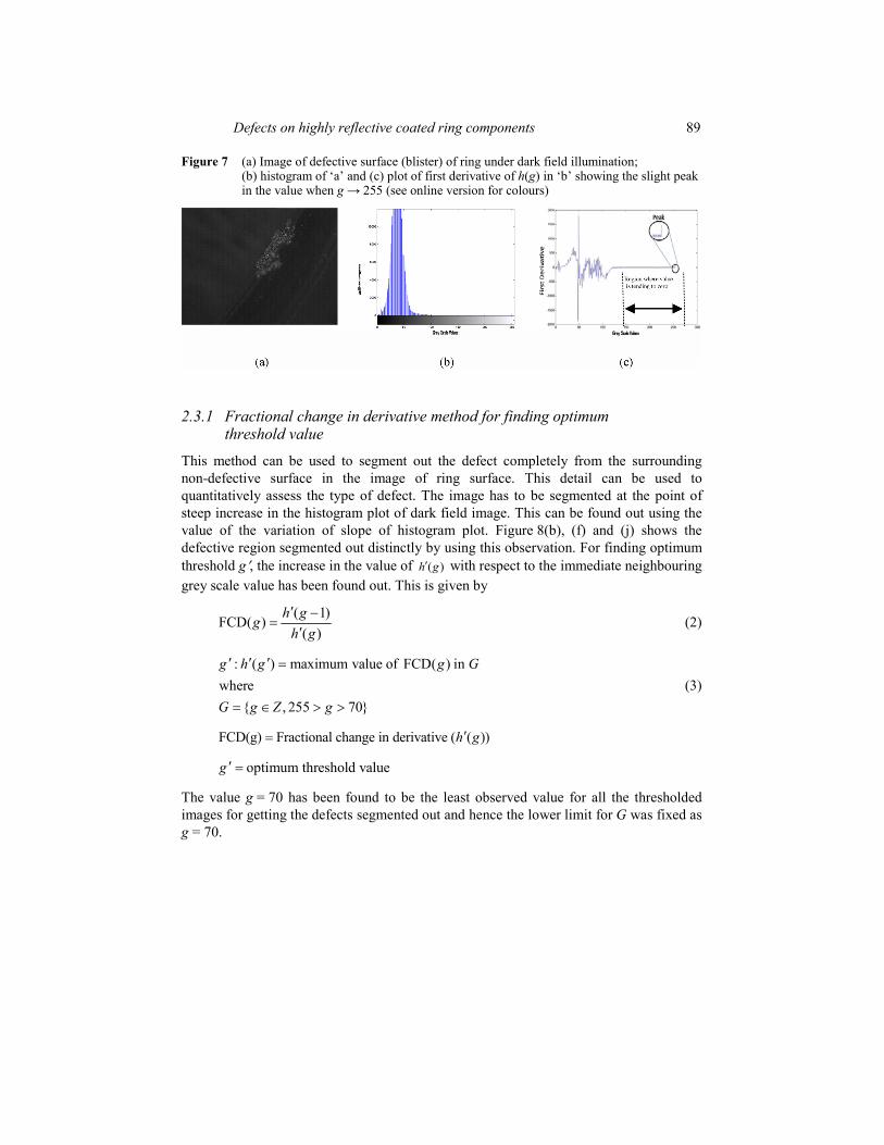
Figure 7 (a) Image of defective surface (blister) of ring under dark field illumination; (b) histogram of ‘a’ and (c) plot of first derivative of h(g) in ‘b’ showing the slight peak in the value when g 255 (see online version for colours)
2.3.1 Fractional change in derivative method for finding optimum threshold value
This method can be used to segment out the defect completely from the surrounding non-defective surface in the image of ring surface. This detail can be used to quantitatively assess the type of defect. The image has to be segmented at the point of steep increase in the histogram plot of dark field image. This can be found out using the value of the variation of slope of histogram plot. Figure 8(b), (f) and (j) shows the defective region segmented out distinctly by using this observation. For finding optimum threshold g , the increase in the value of ( )h g with respect to the immediate neighbouring grey scale value has been found out. This is given by
( 1)FCD( )
( )h g
gh g
(2)
: ( ) maximum value of FCD( ) inwhere
{ , 255 70}
g h g g G
G g Z g (3)
FCD(g) Fractional change in derivative ( ( ))h g
optimum threshold valueg
The value g = 70 has been found to be the least observed value for all the thresholded images for getting the defects segmented out and hence the lower limit for G was fixed as g = 70.
90 M. Singaperumal et al.
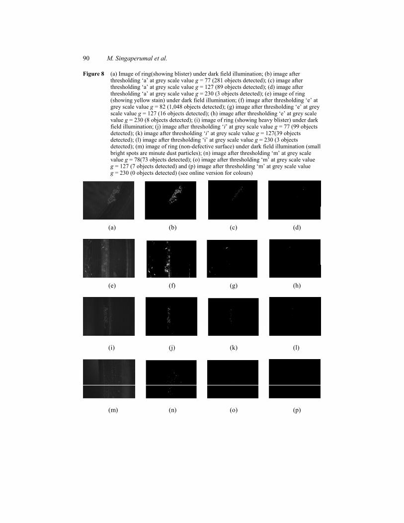
Figure 8 (a) Image of ring(showing blister) under dark field illumination; (b) image after thresholding ‘a’ at grey scale value g = 77 (281 objects detected); (c) image after thresholding ‘a’ at grey scale value g = 127 (89 objects detected); (d) image after thresholding ‘a’ at grey scale value g = 230 (3 objects detected); (e) image of ring (showing yellow stain) under dark field illumination; (f) image after thresholding ‘e’ at grey scale value g = 82 (1,048 objects detected); (g) image after thresholding ‘e’ at grey scale value g = 127 (16 objects detected); (h) image after thresholding ‘e’ at grey scale value g = 230 (8 objects detected); (i) image of ring (showing heavy blister) under dark field illumination; (j) image after thresholding ‘i’ at grey scale value g = 77 (99 objects detected); (k) image after thresholding ‘i’ at grey scale value g = 127(39 objects detected); (l) image after thresholding ‘i’ at grey scale value g = 230 (3 objects detected); (m) image of ring (non-defective surface) under dark field illumination (small bright spots are minute dust particles); (n) image after thresholding ‘m’ at grey scale value g = 78(73 objects detected); (o) image after thresholding ‘m’ at grey scale value g = 127 (7 objects detected) and (p) image after thresholding ‘m’ at grey scale value g = 230 (0 objects detected) (see online version for colours)
(a) (b) (c) (d)
(e) (f) (g) (h)
(i) (j) (k) (l)
(m) (n) (o) (p)

Defects on highly reflective coated ring components 91
In Figure 8 (c), (g) and (k), the threshold value was set as half of the maximum value of 255. Both the threshold values obtained by maximum (fractional change in derivative (FCD)) FCD(g) and g = 127 as it is in this case fails for non-defective images. Hence, a very high threshold value of 230 was fixed such that none of the non-defective areas are segmented out as defects and such images are shown in Figure 8(d), (h) and (l). The image of non-defective sample in Figure 8(m) has been subjected to thresholding based on all the three values and the respective resultant images are shown in Figure 8(n), (o) and (p). It can be found that only Figure 8(p) with threshold value = 230 as discussed before, gives a resultant image with no objects being detected. Based on these observations, it can be concluded that.
1 Threshold value of 230 can be used to identify the presence of defects on the imaged surface.
2 After ascertaining the presence of defects, the maximum FCD(g) method can be used to segment out the defects for further processing. This may be used only on images of defective regions after the identification of defect by using single threshold value of 230, since the non-defective images will give erroneous results when directly operated upon by the algorithm.
3 The images non-defective surfaces will not show any distinct area representing defects while threshold value of 230 is used.
3 Results and discussions
The defect, in particular, ‘blisters’ imaged using bright field illumination is shown in Figure 9(a). The presence of streaks along with the defects makes the histogram multi-modal (Figure 9(d)). Thus, the defect detection may not be easy as it was discussed earlier. There are four major peaks and many more minor peaks each indicating a particular important feature in the image. This shows that features other than this defect are being focused upon. And when observed under axial illumination, this defect appears as presented in Figure 9(b). The streaks are still present, but the histogram (Figure 9(e)) reveals that the defect detection would be simpler than in the previous case. Three major peaks are present and show that the number of features focused upon is lesser than that in the case of bright field illumination. But still, the specular reflection is present and may get detected as a false defect. Further, the same defect observed under dark field illumination (Figure 9(c)) resulted in uni-modal intensity distribution (Figure 9(f)). This clearly shows that the features of the defect alone are focused and the rest are neglected. Hence, the defect segmentation is now a simple thresholding operation (i.e. simplified image processing). The setup used for such a dark field imaging on OD of a ring is shown in Figure 5. With a suitable orientation of camera and illumination, it is possible to image ID or any other curved surface of the ring under dark field imaging conditions. Dark field illumination is found useful, for inspecting inner and outer fillets of the ring, which was nearly impossible when bright field or axial illumination systems were used.
Another kind of coating defect (peel off) imaged using axial illumination is shown in Figure 10(a). The histogram (Figure 10(c)) again follows the same trend as before. The dark field illuminated image of the same defect (Figure 10(b)) gives uni-modal histogram (Figure 10(d)). In short, the dark field illumination gives an image which is uni-modal

92 M. Singaperumal et al.
and thus easy to threshold to detect the defects. The histograms for all the defects in different areas of the ring follow the same pattern. All the images clearly highlight the defective areas leaving out the details of areas that are non-defective. The thresholding as discussed in Section 2.3 helps in quick defect detection. The performance of defect detection algorithms on a Core2Duo 2.8 GHz computer with 2GB RAM, for different imaging conditions is shown in Table 1. The information was deducted from a sample size of 180 images for bright field illumination approach and 210 images for dark field approach.
The algorithm to identify the presence of defect involves a single step thresholding operation by using a value of 230. This single step may be used to ascertain whether the imaged ring is defective or not and is sufficient for simple defect detection. If the defects are to be segmented out distinctly, the FCD approach can be used. This information may be used to find out the actual spread and intensity of defects.
However, applying dark field illumination to specific areas of ring without mutual interference of the light from multiple illumination systems will be difficult. Since the CCD is away from the specular lobe of reflection from the reflective surface in case of dark field illumination, the intensity of light reflected from the defects are always very less and in some cases might cause the defects to be undetected (Figure 11). But still in the image, the defects are in very high contrast from the other non-defective surfaces and thus the defects are easily detected in most cases. Finer details regarding the regular textured surface are lost, since it appears as dark pixels in image and as a result, it cannot be used directly to quantify many of the surface texture features. There is also possibility of pixels getting saturated due to the powerful illumination that is being used which might be dangerous to CCD sensors.
Figure 9 Image of blister in different illumination systems; (a) bright field; (b) axial illumination; (c) dark field illumination; (d) histogram of ‘a’; (e) histogram of ‘b’ and (f) histogram of ‘c’ (see online version for colours)
(a) (b) (c)
(d) (e) (f)

Defects on highly reflective coated ring components 93
In the past, contrast enhancement using different illumination conditions were attempted by earlier researchers on other engineering applications (Bamforth et al., 2007; Piper, 2008). Therefore, there is further scope, here in this case as well, for trying dark field illumination with such contrast enhancement for inspection of defects in these ring components.
Figure 10 Image of peel off in different illumination systems; (a) bright field illumination; (b) axial illumination; (c) dark field illumination; (d) histogram of ‘a’; (e) histogram of ‘b’ and (f) histogram of ‘c’ (see online version for colours)
(a) (b) (c)
(d) (e) (f)
Table 1 Comparison of defect detection algorithms for different illumination setups
S. No. Illumination type and
algorithm used Accuracy of inspection
algorithm Processing/inspection time
per image in seconds
1 Bright field with image convolution method at back end
83% 0.155
2 Dark field with single step thresholding at back end
96% 0.032

94 M. Singaperumal et al.
Figure 11 The schematic diagram of reflective surface and specular lobe of reflection (see online version for colours)
4 Conclusions
In this work, the textile ring components manufactured and supplied by M/s Lakshmi Machine Works Ltd., Coimbatore, India, textile machinery manufacturers were examined for coating defects and the analysis was carried out using different illumination techniques. Particularly, the advantages of using dark field illumination have been highlighted in this case study. Based on the results and analysis the following conclusions are drawn.
It was clearly observed that the dark field illumination was advantageous in the sense that the image processing became simpler because of the improved quality of images obtained. Therefore, the entire process of defect detection became faster. When using the dark field illumination, the effect of bands of reflective regions was absent. These bands were occurring due to specular reflections in axial and bright field illumination. The presence of defect on a dark field illuminated image can be identified using a single thresholding operation rather than using complex image processing algorithms as discussed in Section 1.1. The entire process of identification of defects by using simple thresholding operation was faster by approximately 4 times, when compared with standard image processing algorithm based on image convolution approach on bright field images. There is scope for further improvement if the image processing set-up is coupled with higher magnification lenses, even very small defects can be easily detected.
This study clearly indicates that the automatic inspection of ring components using machine vision could be successfully implemented and the entire process of inspection could also be made much faster and reliable.

Defects on highly reflective coated ring components 95
References Aluze, D., Merienne, F., Dumont, C. and Gorria, P. (2002) ‘Vision system for defect imaging,
detection, and characterization on a specular surface of a 3D object’, Image and Vision Computing, Vol. 20, No. 8, pp.569–580.
Bamforth, P.E., Jackson, M.R. and Williams, K. (2007) ‘Transmissive dark-field illumination method for high-accuracy automatic lace scalloping’, Int. J. Advanced Manufacturing,Vol. 32, Nos. 5–6, pp.599–607.
Biss, D.P., Youngworth, K.S. and Brown, T.G. (2006) ‘Dark field imaging with cylindrical-vector beams’, Applied Optics, Vol. 45, No. 3, pp.470–479.
Connolly, C. (2002) ‘Lighting for industrial inspection’, Sensor Review, Vol. 22, No. 2, pp.106–112.
David, M. (2008) Dark Field Illumination. Available at: http://encyclopedia.jrank.org/ articles/pages/1126/Darkfield-Illumination.html, Accessed on 25 October 2009.
Khalili, K. and Webb, P. (2007) ‘The development and application of a multiple wavelength illumination technique for the vision-based process monitoring of aero-structure riveting’, Machine Vision and Applications, Vol. 18, No. 2, pp.73–83.
Lee, M.R., de Silva, C.W., Croft, E.A. and Wu, Q.M.J. (2000) ‘Machine vision system for curved surface inspection’, Machine vision and Applications, Vol. 12, No. 4, pp.177–188.
Martin, D. (2007). A Practical Guide to Machine Vision Lighting. Available at: http://advancedillumination.com/uploads/downloads/A%20Practical%20Guide%20to%20 Machine%20Vision%20Lighting.pdf. Accessed on 1 February 2009.
Miyoshia, T., Takahashia, S., Takayaa, Y. and Shimadab, S. (2001) ‘High sensitivity optical detection of oriented microdefects on silicon wafer surfaces using annular illumination’, CIRP Annals – Manufacturing Technology, Vol. 50, No. 1, pp.389–392.
Noda, N. and Kamimura, S. (2008) ‘A new microscope optics for laser dark-field illumination applied to high precision two dimensional measurement of specimen displacement’, Review of Scientific Instruments, Vol. 79, No. 023704, pp.1–7.
Piper, J. (2008) ‘Luminance contrast, a new illumination technique in light microscopy: optical basics, practical evaluations, further developments’, Optik: International Journal for Light and Electron Optics, doi:10.1016/j.ijleo.2008.03.032.
Povolo, F., Canzian, A. and Favret, E (1997) ‘Unidirectional laser oblique illumination (ULOI): a comparison with partial dark field illumination (PDFI) in the optical microscopy of metals’, Applied Optics, Vol. 29, No. 2, pp.67–73.
Rosati, G., Boschetti, G., Biondi, A. and Rossi, A. (2009) ‘Real-time defect detection on highly reflective curved surfaces’, Optics and Lasers in Engineering, Vol. 47, Nos. 3–4, pp.379–384.

96 M. Singaperumal et al.
Appendix
Accuracy of algorithm
A given number of ‘known quality sample images’ (both defective and non-defective) are processed using images from each of the illumination set ups. The similar defects are imaged using both the set ups and then tested by using the corresponding algorithms, that is, single step thresholding for dark field and image convolution method for bright field images. Then the result is analysed for accuracy by finding out the number of correct identification for the samples. Algorithm accuracy is based on the number of defective/non-defective samples that have been correctly classified/identified by the system. The definition is given below.
Number of defective sample images classified as defective by algorithmNumber of non-defective sample imageAccuracy
Total number of sample images