identification of halo orbits for energy efficient
TRANSCRIPT

IDENTIFICATION OF HALO ORBITSFOR ENERGY EFFICIENT FORMATION FLYING
Oliver JUNGE�, Jens LEVENHAGEN
�, Albert SEIFRIED
�and Michael DELLNITZ
��Departmentof ComputerScience
ElectricalEngineeringandMathematicsUniversityof Paderborn
33095PaderbornGermany
�AstriumGmbH
88039FriedrichshafenGermany
ABSTRACT – This contribution is concernedwith the numerical simulationof spacecraft formationdynamicson Halo orbits around the Sun-Earth librationpoints.Thecircular restrictedthree-bodyproblem(CRTBP)in rotatingcoordinatesservesastheanalyticalframework. Theprimarygoal is to identifyregionsin phasespacein which theuncontrolled dynamicsinducesonlyverysmallperturbationsonsatellite formationsandthusallow for an energy-optimalformationkeepingstrat-egy. This obviouslyleadsto lower cost and massbudgets and longer operationtimes.Theresultsobtainedhere indicatethat it is possibleto performan accurateformation keepingaroundthelibration pointspurely basedon low thrustmanoeu-vres.Thiswill beof particular importancewith regard to upcominglow thrustmis-sionssuch asDARWIN.
1 INTRODUCTION
Halo orbits1 have beenidentifiedasconvenientlocationsfor positioning singlespacecraftandhavealreadybeenemployedfor a varietyof missions (e.g.NASA’s GENESISDiscovery Mission).Basedon theexperiencewith thesesinglespacecraft,alsoupcoming formationmissionslike DARWIN areforeseento operatein thevicinity of a Halo orbit aroundoneof theSun-Earthlibration points. Thislocationyields the greatadvantageof very small gravitational disturbanceforcesand is thereforevery well suitedfor missionswith extremelyhighperformancerequirements.Simultaneouslylongerformationoperationtimesaswell aslowercostandmassbudgetsareguaranteed.
Concerningthesemissions the following important questionarises:cana Halo orbit be foundwherea formationwith several hundredmetersor even kilometersof distancebetweenthe partic-ipating spacecraftcould be maintained exclusively by low-thrust maneouvres– i.e. the maximumrequiredaccelerationis in theorderof or below ���������� �� ? In thatcasethepropellantconsumptiondueto formationcontrolcouldbeneglectedin comparisonto thatdueto orbit control.In this articlewe presentanapproachwhich leadsto theidentificationof Halo orbitsaroundthe � � libration pointwith thisdesiredproperty.
2 MODELLING FORMATION FLIGHT
Consideringonly gravitational forces,the mathematical modelfor the motion of several spacecraftis givenby an � -bodyproblem, i.e. by a setof coupledsecondordernonlinearordinarydifferentialequations: �������� ���� � ��"!�$# &% � %(' ���) � %(' ��� )+*�, - � � ,�.�.�.$, � . (2.1)
1 ThenameHalo orbit is dueto thefactthatit appearsasa haloaroundtheSunwhenviewedfrom behindtheEarth.
Here � %�/10 * is theposition of the 2 -th bodyunderconsideration,3% is its massand � is thegrav-itational constant.For spacecraftdynamicsthis systemcanbe significantlysimplified by usingthefollowingfacts:(1) themassesof thespacecraftareseveralordersof magnitudesmallerthanthoseoftheplanetsandtheSun,(2) thegravitational forcesbetweenthespacecraftarenegligible comparedwith theothers,(3) up to adistanceof approximately� . �4� AU from theEarththegravitationalforcesof the Sunandthe Earthareat leasttwo ordersof magnitudelarger thanthoseof the otherplanetsandthe Moon [Sei02].By neglectingthe correspondingforce termsin (2.1) oneendsup with a 5 -bodyproblemmodelling theflight of eachof thespacecraftseparately. Furthersimplification of thismodel is achieved by restrictingthe motion of the Sunandthe Earth to circleswhich leadsto thewell-known circular restrictedthreebodyproblem(CRTBP)2. Its equationsof motion in a rotatingcoordinateframearegivenby [Wie98]
��6�87:9;=<1�><@?�A$BC�><ED 'F�HG <E? � BI�J<1D G�;K� ' 7:9�J<1;L<MBN?�AO<E? � G ; (2.2)�P=�QBR?�AS<@? � G P ,where BC� , ; , P G denotedimensionlesscoordinateswith
?�AT� ' DBBC�><ED 'F�HG � <1; � <EP � GVUW , ? � � ' �X' DBBI�J<ED G � <E; � <@P � GHUW (2.3)
and DY� A � B AO< � G � 5 . �[Z �[Z 7 5�5�\�][Z[Z�Z^�H_[`Xa�������b is thenormalizedmassof theEarth.
3 GENERATION OF HALO ORBITS
3.1 Computation of Halo orbits
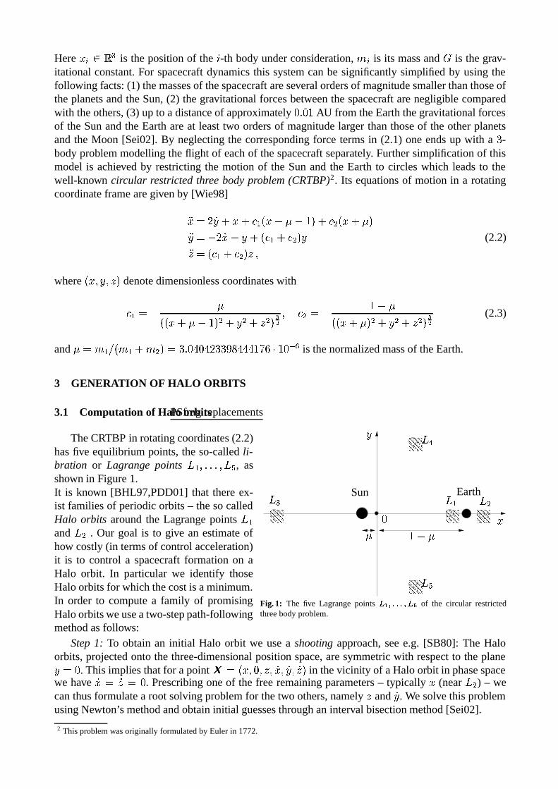
TheCRTBP in rotatingcoordinates(2.2)hasfive equilibriumpoints,the so-calledli-bration or Lagrange points � A ,�.�.�.$, �Tc , asshown in Figure1.It is known [BHL97,PDD01] that thereex-ist familiesof periodicorbits– thesocalledHalo orbits aroundthe Lagrangepoints � Aand � � . Our goal is to give an estimateofhow costly(in termsof controlacceleration)it is to control a spacecraftformationon aHalo orbit. In particular we identify thoseHaloorbitsfor whichthecostis aminimum.In order to computea family of promisingHaloorbitsweuseatwo-steppath-following
deddedfeffef geggeghehheh
ieiieijejjej
kekkeklellel
memmemnennen
PSfragreplacements
� A � �� *
�po
�Tc
EarthSun
�
;
�X' DD �
Fig. 1: The five Lagrangepoints q �srutststvr q�w of the circular restrictedthreebodyproblem.
methodasfollows:Step1: To obtainan initial Halo orbit we usea shooting approach,seee.g. [SB80]: The Halo
orbits,projectedonto the three-dimensionalposition space,aresymmetricwith respectto theplane;J� � . This impliesthatfor apoint x �yBC� , � , P , 9� , 9; , 9P G in thevicinity of aHaloorbit in phasespacewe have 9�z� 9P�� � . Prescribingoneof the free remainingparameters– typically � (near � � ) – wecanthusformulatea root solvingproblemfor thetwo others,namely P and 9; . We solve this problemusingNewton’smethodandobtaininitial guessesthroughaninterval bisectionmethod[Sei02].
2 Thisproblemwasoriginally formulatedby Eulerin 1772.

Step 2: Once a Halo orbit is found for aprescribed � we get a nearby orbit of thefamily by a standardpredictor-correctorap-proach: we slightly vary � in x and usethis point asa new initial guessfor Newton’smethod.Figure2 shows a family of Halo or-bits around � � which was computedby themethoddescribed.The line joining the Haloorbitsmarksthepoints BC� , � , P G whichparam-eterisethe family. In the following sectionswe will usethe � -coordinateof thesepointsin orderto referto aspecificorbit of this fam-ily. We further refer to [TW96] for a similarapproachto thecomputationof Haloorbits.
0.999 1.0016 1.0042 1.0068 1.0094 1.012
−0.01
0
0.01
−12
−10
−8
−6
−4
−2
0
2
4
x 10−3
L2
x (AU)
E
y (AU)
z (A
U)
Fig. 2: Family of Halo orbits in the vicinity of the Lagrangepoint q W(projectionontopositionspace).
3.2 Stability Analysis for Halo orbits
In order to get a first impression of the dynamicsin the vicinity of the Halo orbits we com-putetheir Floquetmultipliers.By definition,theFloquetmultipliers of a periodicsolution determineits stability [Hal80]. They areobtainedvia in-tegratingthevariationalequationover a wholeperiodof the correspondingperiodicsolution.InspectingFigure 3 we note that there existsomeorbitsneartheEarthfor which the mag-nitudeof all Floquetmultipliers is equalto � .Indeed,a long-time integration of theseorbitsindicatesthat they arestable.We observe thatthelargestFloquet-multiplier increasesin mag-nitudeasonemoves alongthe family of Haloorbits away from the Earth. Since this mul-tiplier determineshow quickly trajectoriesdi-vergefrom eachother, onecouldbetemptedtoarguethatin orderto achievea low energy con-trol of a formationa Halo orbit nearthe Earthshouldbeselected(seealso[BHL97]).
1 1.002 1.004 1.006 1.008 1.0110
−4
10−3
10−2
10−1
100
101
10
103
104
x (AU)
Flo
quet
mul
tiplie
rs
largestsmallest
PSfragreplacements
� �
Fig. 3: Magnitudeof the Floquetmultipliers of the family of Haloorbitsin Figure2.
However, we intend to use continuouslyappliedlow thrust control on the spacecraft,thus in our caseit is more interestingto ob-tain statementsaboutthe local dynamicson amuchshortertimescale.To thisend,wecom-putefinite timeLyapunov multipliers (FTLM)in an analogousway asthe Floquetmultipli-ersbefore:but hereweonly integratethevari-ational equationfor times {}| � ~*u�u� (whichcorrespondsto a flight time of approximately��Z hours).See[Lor65] for the relatednotionof finite timeLyapunov exponents.We repeatthis computation alongeachHaloorbit andfor the whole family that wascom-puted in the previous section.The result isshown in Figure4. Wenotethatthemaximum
log
(fin
ite ti
me
Lyap
unov
mul
tiplie
r −
1)
10
−1.5
−1
−0.5
0
1 1.001 1.002 1.003 1.004 1.005 1.006 1.007 1.008
0.5
1
1.5
2.5
3
3.5
4
4.5
5
5.5
x (AU)
time
(mon
ths)
PSfragreplacements
Fig. 4: Magnitude of the largest finite time Lyapunov multiplier(FTLM) along eachHalo orbit of the family in Figure 2. The blackline markstheperiodof theHalo orbits.
of thelargestFTLM over oneHalo orbit decreaseswhenwe move alongtheHalo orbit family awayfrom Earth.Sincethe largestFTLM determineshow mucha given formationof spacecraftis perturbedunderthe uncontrolleddynamicswithin the time spanunderconsideration,one hasto draw the reverseconclusionasfrom theresultsshown in Figure3: oneshouldnot placetheformationin thevicinityof anearEarthHaloorbit. A moredetailedexplanationis givenin thenext section.
4 DEFORMATION UNDER UNCONTROLLED DYNAMICS
Weanalyseto whatextentagiven formationis deformedwhenevolving uncontrollednearan � � Haloorbit. Hencewe considera particularformation,propagateeachof thespacecraftusingtheCRTBP(2.2),anddeterminethetime-dependentdeviationsof thespacecrafts’positionsfrom thedesiredones.Moreover we determinehow muchtheattitudeof theformation(given by thenormaldirectionon aplanedefinedby thepositionsof thespacecraft)changeswith time.This is alsoof particularinterestin thecontext of missionslikeDARWIN.
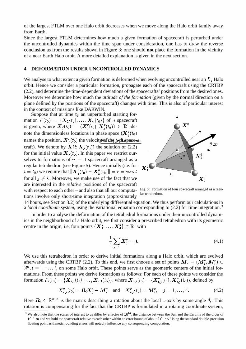
Supposethat at time | � an unperturbedstartingfor-mation � B | � G � � x A�B | � G ,�.�.�.$, x � B | � G+� of � spacecraftis given, where x ��B | � G � B x��� B | � G , xE�� B | � GG�/�0�b de-notethedimensionlesslocationsin phasespace( x��� B | � Gnamestheposition, x � � B | � G thevelocityof the - -th space-craft). We denoteby x B |+��x ��B | � G�G the solution of (2.2)for theinitial value x �VB | � G . In this paperwe restrictour-selves to formationsof � � Z spacecraftarrangedasaregulartetrahedron(seeFigure5). Henceinitially (i.e. for| � | � ) we requirethat
) x��� B | � Gp'1x��� B | � G ) ��?��Q?�� �S �|for all -z���� . Moreover, we make useof thefact thatweare interestedin the relative positionsof the spacecraftwith respectto eachother– andalsothatall ourcomputa-tions involve only short-time integration (approximately
PSfragreplacements
x � A
x ��
x �*x��o
� A � *� �%?
Fig. 5: Formationof four spacecraftarrangedasaregu-lar tetrahedron.
14hours,seeSection3.2)of theunderlyingdifferentialequation.Wethusperformourcalculationsina local coordinatesystem, usingthevariationalequationcorrespondingto (2.2) for time integration.3
In orderto analysethedeformationof thetetrahedralformationsundertheiruncontrolleddynam-ics in theneighborhoodof a Halo orbit, we first considera prescribedtetrahedronwith its geometriccentrein theorigin, i.e. four points � x � A ,�.�.�.�, x �o ���80 * with
�Zo� ����A x �� � � . (4.1)
We usethis tetrahedronin order to derive initial formations alonga Halo orbit, which areevolvedafterwardsusingtheCRTBP (2.2).To this end,we first choosea setof points � % ��B � �% , � � % G�/0 b , 2 � � ,�.�.�.�,�¡ , on someHalo orbit. Thesepointsserve asthe geometriccentersof the initial for-mations. Fromthesepointswederive formationsasfollows:For eachof thesepointsweconsidertheformation �¢% B | � G �£� xF%¥¤ A$B | � G ,�.�.�.�, x�%¥¤ o B | � G+� , where x�%"¤ ��B | � G �¦B x �%¥¤ � B | � G , x � %¥¤ � B | � G�G , definedby
xM�%"¤ � B | � G ��§ %Ix��� < �¨�% and xE� %¥¤ � B | � G � �©�% , - � � ,�.�.�.�, Z . (4.2)
Here § %ª/�0 *�«[* is the matrix describinga rotationaboutthe local P -axis by someangle ¬ % . Thisrotationis compensating for the fact that theCRTBP is formulatedin a rotatingcoordinatesystem,3 We alsonotethatthescalesof interestto usdiffer by a factorof u® � U : thedistancebetweentheSunandtheEarthis of theorderofu® �I�4¯ andwehold thespacecraft relativeto eachotherwithin anerrorboundof about ® t ®+ ¯ . Usingthestandarddouble-precision
floatingpoint arithmeticroundingerrorswill notablyinfluenceany corresponding computation.

but – in view of missions like DARWIN – we want the formation to maintainan inertially fixedorientation.Soin (4.2)we first rotatethetetrahedron� x � A ,�.�.�.$, x �o � , suchthatwe obtainthecorrectattitudeandthenmove it ontotheHaloorbit suchthatits geometriccenteris � �% afterwards.
Thesumof differencesbetweenactualanddesirededgelengths
° % B |�G �£� � A� ���A ��� � ��±�A²²²²²) x �%¥¤ � B |�G³'1x �%¥¤ � B |�G )) x��%¥¤ � B | � G³'1x��%¥¤ � B | � G ) 'F�
²²²²² (4.3)
is a measurefor the deformationof the formation �T% B |�G . Herewe abbreviatednotationby writingx �%¥¤ � B |�G for thepositionspacecoordinatesof thesolution x B |+��x�%"¤ ��B | � GG . In ordertoattributeaspecificdirectionto a formation �³% B |�G ��� x�%¥¤ A�B |�G ,�.�.�.�, x�%¥¤ o B |�G+� , we choosethreespacecraftxF%"¤ A�B |�G , xF%"¤ � B |�Gand x�%¥¤ * B |�G from �´% B |�G anddefinetheattitudeof �¢% B |�G by theaccompanying planeunit normalvector
µ % B |�G � B x �%¥¤ � B |�G³'1x �%¥¤ A B |�GG:¶ B x �%"¤ * B |�G³'1x �%¥¤ A B |�GG) B x��%¥¤ � B |�G³'1x��%¥¤ A B |�GG:¶ B x��%"¤ * B |�G³'1x��%¥¤ A B |�GG )·. (4.4)
Basedon thisapproachonecandefinethetilt angleof theformationat time | as
¸ % B |�G �M¹�º»�»$¼�½HB µ % B | � G³a µ % B |�GG . (4.5)
Example: In the following computa-tions we usean edgelengthof Z 5�5T be-tweenthe four spacecraft.We usea setof¡ � 5���� points on the Halo orbit that weobtainedby integrating alongtheorbit forperiods{}| � ~*u�u� . (Here 7V¾ correspondstooneyear;theHalo orbitshave periodsbe-tween4 and6 months.) For this {}| andforevery 2 � � ,�.�.�.$,�¡ thedeformation
° % B | � <{ª|�G andthetilt angle % B | � < {}|�G arecom-puted.Figure6 shows theresultfor anini-tial tetrahedronwith arandomlychosenat-titude on the Halo orbit throughthe pointx �¿B � . ����À�_ , � , � . �[�[Z�Z , � , � . ���H_[\ , � G witha period of approximately ��_�_ days.Wenote that thoughwe have chosenthe atti-
0 1 2 3 4 5 60
0.02
0.04
0.06
0.08
0.1
0.12
tilt a
ngle
(de
g)0 1 2 3 4 5 6
0
0.2
0.4
0.6
0.8
1
1.2
1.4x 10
−3
time (months)
defo
rmat
ion
(/)
ÁD
Fig. 6: Deformation/tiltangleof a spacecraftformationalongan q W Haloorbit.
tudeof the initial tetrahedronat random,theresultis representative in thesensethatdifferentinitialtetrahedraleadto comparableresults.
Thiscomputationis performedfor theentirefamily of Haloorbitsof Section3 where,in addition,we averagethe resultfor eachHalo orbit over ����� initial tetrahedrawith randomlychosenattitude.The resultsareshown in Figure7. The abscissaparameterisesthe family of orbitsandthe ordinaterepresentstime, i.e. parameterisesthesetof points � % . Theshadingindicatesthedeformation(leftsubplot) andthe tilt angleof the formation(right subplot) in a logarithmic scale,respectively. Notethatthesetwo figurescloselyresembleFigure4.
In Figure8 thetwoquantitiesaredisplayedin adifferentway. Thistimetheirminimum,maximumandmeanvaluesover eachof the Halo orbits of the family are shown, respectively. Observe thatthemeandeformationexhibits a local minimum at approximately �E� � . ����` À (seeFigure8 (left)).However, for practicalpurposesthe existenceof this minimum is of minor importance.Ratherweobservethatthemeanandthemaximum deformationandtilt angleof a formationunderuncontrolleddynamicsalonga Halo orbit essentiallydecreaseswhenwe move alongthe family of Halo orbitsaway from theEarth.Thuswe draw theconclusionthatHalo orbits furtheraway from theEarthare

log 10
(def
orm
atio
n)
−3.5
−3
−2.5
−2
−1.5
1 1.001 1.002 1.003 1.004 1.005 1.006 1.007 1.0080
1
2
3
4
5
6
x (AU)
time
(mon
ths)
log 10
(tilt
ang
le)
(deg
)
−1.5
−1
−0.5
0
0.5
1 1.001 1.002 1.003 1.004 1.005 1.006 1.007 1.0080
1
2
3
4
5
6
x (AU)
time
(mon
ths)
Fig. 7. Deformation(left) andtilt angle(right) of a spacecraftformationalongthe q W Halo orbit family from Figure2. Theblacklinesmarktheperiodof theHalo orbits.
1 1.001 1.002 1.003 1.004 1.005 1.006 1.007 1.008
10−3
10−2
x (AU)
defo
rmat
ion
(/)
mean(D)max(D)min(D)
1 1.001 1.002 1.003 1.004 1.005 1.006 1.007 1.008
10−1
100
x (AU)
tilt a
ngle
(de
g)mean(Â )max(Â )min(Â )
Fig. 8. Minimum, maximumandmeandeformation(left) andtilt angle(right) of aspacecraft formationalongthe q W Haloorbit familyfrom Figure2.
bettersuitedfor anenergy efficient formationflight (which obviouslyconfirmsour interpretationofSection3.2).In thenext sectionwewill seethatthisconclusionis furthersupportedwhenacontrolledflight of spacecraftis considered.
5 LOW THRUST CONTROL STRATEGY
This sectioncomplements the resultsof the previous sectionswith the analysisof a certaincontrolstrategy for stabilizing thespacecraftformationon an � � Halo orbit. Our approachis asfollows: Weaddcontrolaccelerationtermsà �yBRÄ(Å , ÄÇÆ , Ä·È G to equation(2.2),yielding thesystem��6�87:9;=<1�><@?�A$BC�><ED '8�HG <E? � BI�J<1D G <EÄÇÅ�;�� ' 7:9�J<1;L<MBN?�AO<E? � G ;L<1Ä·Æ (5.1)�P=�QBR?�Ae<@? � G PÉ<EÄ·È .The solutionof (5.1) will thusdependon the control function à � à B |�G , i.e. startingin x B | � G andapplyingthe control function à onearrivesat x B |+�Êà , x B | � GG . We cannow formulateour controlproblemasfollows: givensomeactualformation �ÌË �Í� x A�B |�G , .�.�. , x � B |�G+� at eachtime instance|

andaprescribedreferenceformation �OË ±ÇÎ Ë ��� x A�B | < {}|�G , .�.�. , x � B | < {}|�G�� at | < {ª| , find controlfunctionsà �Ï� à �[B |�G , suchthat
x B {}|+�Êà � , x ��B |�G�G � x �[B | < {ª|�G for - � � ,�.�.�.�, � . (5.2)
Motivatedby physical considerations(i.e. the designof the spacecraftthrusters)we make the as-sumption, thatthecontrolfunctionsà �VB |�G arepiecewiseconstant.If werestrictourselvesto two “timesteps”perperiod {ª| (i.e. à ��B |�G is constanton ÐÑ| , | < {}|�� 7VÒ andconstantbut eventuallydifferentonÐÑ| < {ª|�� 7 , | < {}| Ò ), equation(5.2)yieldsasystemof six equationsandsix unkowns.If wechoose{}|sufficiently smallandif theactualformationis “sufficiently close”to thereferenceformation,wecansolve thissystemusingNewton’smethod.
0 1 2 3 4 5 60
0.5
1
1.5
2x 10
−10
time in months
cont
rol i
n m
/s2
1234mean
log 10
(con
trol
) (m
/s2 )
−10
−9.5
−9
−8.5
−8
1 1.001 1.002 1.003 1.004 1.005 1.006 1.007 1.0080
1
2
3
4
5
6
x (AU)
time
(mon
ths)
Fig. 9. Left: Magnitudeof the control acceleration(for eachspacecraftseparatelyand their mean)along someHalo orbit. Right:Magnitudeof controlaccelerationalongtheHalo orbit family of Figure2.
Figure9 (left) shows the magnitude of the requiredcontrol accelerationin dependenceof timealong a certainHalo orbit (the one we usedin Section4). Note the qualitative similarity to Fig-ure 6. We repeatthe samecomputation forthe whole family of Halo orbits andaveragetheresultsover50randomlychosenreferenceformations.The result is shown in Figure 9(right). As expectedit bearsa strongresem-blancewith Figures4 and7.In Figure 10 we plot the minimum, maxi-mumandthemeancontrolaccelerationalongthe Halo orbit family. Again, these valuesshow thesamedependenceasthedeformationwhichhasbeencomputedin theprevioussec-tion (Figure8). But moreimportantis thefactthat Halo orbits can be identified with a re-quired maximumcontrol acceleration below���������� �� which makes it possibleto keepthevehiclesin a stableformationonly by low
1 1.001 1.002 1.003 1.004 1.005 1.006 1.007 1.008
10−10
10−9
10−8
cont
rol (
m/s
2)
mean(control)max(control)min(control)
Fig. 10: Minimum, maximumandmean(over oneperiod)control ac-celerationalongthatfamily.
thrustactuation.

6 DISCUSSION
Basedon theCRTBP givenin a rotatingcoordinateframe,we presentanapproachto identify Haloorbitsaround� � whicharesuitablelocationsfor anenergy efficient formationflight. Within thatcon-text theevaluationof finite timeLyapunov multipliers indicatesthatpromisingHaloorbitsarelocatedat somedistancefrom theEarth.A detailedanalysisof thedynamicalbehaviour of uncontrolled aswell ascontrolledformationsverifiesthis importantresult.
In all the computations we useformationsof four spacecraftarrangedas a tetrahedronin thevicinity of Halo orbitsaround� � . Energy efficiency is derivedfrom two local deformationmeasuresanda simple but straightforward control strategy is employed. The resultsobtainedcontradicttheconclusionswhichonemightdraw from ordinaryFloquetmultipliersanalysis.
As a very importantresultit is shown thata lifetime formationcontrolonly basedon low thrustactuationis possible.Regardingfuturemissiondesign,thiswill allow to neglectpropellantconsump-tion dueto formationcontrolcomparedto thatdueto orbit control.However, thepropellantneededfor thereconfigurationof a formationis not takeninto accountandwill bea topicof our futurework.
References
[BHL97] B.T. Barden,K.C. Howell, and M.W. Lo. Application of dynamicalsystemstheory totrajectorydesignfor a libration point mission. J. of the Astronautical Sciences, 45(2):161–178,1997.
[Hal80] J.K.Hale. Ordinarydifferential equations. Wiley-Interscience,1980.[Lor65] E.N. Lorenz. A study of the predictability of a 28-variableatmosphericmodel. Tellus,
17:321–333,1965.[PDD01] R.C.Paffenroth,E.J.Doedel,andD.J.Dichmann.Continuation of periodicorbitsaround
LagrangepointsandAUTO2000. In Proc. AAS/AIAAAstrodynamicsSpecialistConference,2001.AAS paper01-303.
[SB80] J.StoerandR. Bulirsch. Introductionto numericalanalysis. Springer,1980.[Sei02] A. Seifried. NumerischeUntersuchungenzum Formationsflugvon Raumfahrzeugen.
Diplomathesis,Universitat Paderborn,2002.To bepublished.[TW96] R. ThurmanandP.A. Worfolk. Thegeometryof haloorbits in thecircular restrictedthree
bodyproblem.TechnicalReportGCG95,GeometryCenter, University of Minnesota,1996.[Wie98] B. Wie. SpaceVehicleDynamicsandControl. AIAA EducationSeries.AIAA, 1998.