idsusermanual eng v1.0 - · pdf fileids user manual v1.0 page 2 of 46 march 21, 2012...
TRANSCRIPT
UUse
Re
er M
elease: M
Ma
March 2
anu
21, 2012
ual

Trademark Acknowledgements
Ford is a registered trademark of Ford Motor Company.
Copyright Information IDS User Manual Copyright © 2012 Ford Motor Company.
The information, specifications and illustrations in this manual are based on the latest information available at the time of printing. Ford Motor Company reserves the right to make changes at any time without notice.

CONTENTS
Introduction ................................................................................................................................................................... 1 Application Overview ................................................................................................................................................ 1 Diagnostic Link Connector (DLC) Cable ...................................................................................................................... 1 PC USB Interface Cables ............................................................................................................................................ 1 Vehicle Interface Devices........................................................................................................................................... 1 Downloading and Installing IDS Software on a PC..................................................................................................... 2 IDS Software License ................................................................................................................................................. 2 Updating IDS and VCM II Software ............................................................................................................................ 4
Case I: VCM II Software Version is older than that required by IDS ..................................................................... 4 Case II: VCM II Software Version is Newer than that Required by IDS ................................................................. 4 How to Factory Reset Your VCM II ....................................................................................................................... 6
System Navigation ......................................................................................................................................................... 7 System Set Up and Information ..................................................................................................................................... 8 User Preferences ....................................................................................................................................................... 8 System Information ................................................................................................................................................... 8 System Utilities .......................................................................................................................................................... 8
Vehicle ID and Session Management .......................................................................................................................... 11 Start New Session .................................................................................................................................................... 11 Manual Vehicle Entry ............................................................................................................................................... 12 Vehicle Specification ................................................................................................................................................ 14 Log Viewer ............................................................................................................................................................... 14 Close Session ........................................................................................................................................................... 15 Restoring a Vehicle Session ..................................................................................................................................... 16
Toolbox ........................................................................................................................................................................ 18 Device Selection .......................................................................................................................................................... 32 Establishing a Connection to a Wired VCM ............................................................................................................. 33 Establishing a Connection to a Wireless VCM II ...................................................................................................... 34
Acronyms ..................................................................................................................................................................... 36 Symbols (Functional Groups) ....................................................................................................................................... 40 Glossary of Symbols (Alphabetical) ............................................................................................................................. 42

IDS User Manual
V1.0 Page 1 of 46 March 21, 2012
INTRODUCTION
APPLICATION OVERVIEW
Integrated Diagnostic System (IDS) uses Ford proprietary software to run on a Windows based PC (Laptop, Mini Laptop, Desktop, Netbooks, etc.) with the Vehicle Communication Module (VCM), and the Vehicle Measurement Module (VMM).
NOTE: Throughout this manual the term "VCM" refers to both the VCM and VCM II unless specific reference is made to a particular interface device. For additional information, see the VCM or VCM II Hardware Manual.
A comprehensive, in‐depth tutorial, IDS training course is available on‐line (see web links below). The IDS training course covers IDS installation, setup, updates, as well as basic tool functions using the VCM and VMM in diagnosing vehicles and much more.
• Ford Dealers (IDS Training Course) http://www.fordtechservice.dealerconnection.com/vdirs/protech/global/default.asp
• All Others (IDS Training Course) http://www.motorcraftservice.com/vdirs/training/cdatabase/training_mc_cdatabase.asp?CourseID=30G11W1&mode=course
DIAGNOSTIC LINK CONNECTOR (DLC) CABLE
The VCM 16‐pin DLC cable is used to connect the VCM to the vehicle DLC.
PC USB INTERFACE CABLES
The VCM and VMM connect to the PC using the custom Ethernet‐USB Adapter Cable (H406/H416). The VCM II connects to the PC using a commercially available USB 2.0 cable.
VEHICLE INTERFACE DEVICES
The vehicle interface devices that are used with this application are:
• Vehicle Communication Module (VCM) – This device provides all link based functionality including: Datalogger, Selftest, Service Functions, Module Configuration and Programming, etc.
• Vehicle Measurement Module (VMM) – This device provides the following functionality: Oscilloscope, Digital Multi‐Meter, Ignition System Test, Fuel System Test, and SGM.
NOTE: The software application will detect the interface device that is connected to the PC. Indicator icons will appear at the bottom right‐hand corner of the IDS screen when the VCM and/or VMM are connected.

IDS User Manual
V1.0 Page 2 of 46 March 21, 2012
DOWNLOADING AND INSTALLING IDS SOFTWARE ON A PC
NOTE: Installing and configuring IDS requires Windows Administrative privileges
To run your computer with Windows Administrative privileges go to Windows Start, then select Help and Support and type "Change a user's group or account type" in the Search box.
• Ford Dealers http://www.fordtechservice.dealerconnection.com/vdirs/wds/diagnosticsites/vcmdvd/idssoftware.asp and download the latest IDS software
• All Others http://www.motorcraftservice.com/vdirs/wds/diagnosticsites/vcmdvd/mcs/idssoftware.asp and download the latest IDS software‐
See http://www.fordtechservice.dealerconnection.com/vdirs/wds/idsmanual/IDS_Webdownload.PDF for additional help with IDS Software Download & Installation.
See http://www.fordtechservice.dealerconnection.com/vdirs/wds/idsmanual/IDSInstructions_US_ENG.pdf for additional help with IDS Calibration & Software Update Process.
IDS SOFTWARE LICENSE
IDS Software License is subscription based.
Main points about the IDS Software Licensing subscription:
• The license subscription is for a fixed time period. When it expires, it will disable use of vehicle communications functionality within IDS.
• The license is activated on a computer using IDS and is independent from the VCM [i.e., any VCM may be used]
• Each computer requires a license to use IDS for vehicle communication • A license can only be used on one computer at a time • A unique license Activation Code is provided with each software subscription. The license activation code
is entered in IDS to activate the software shown in Figure 1. • A license may be activated using an online or offline process. • A license can be returned online and then activated on a different computer online or offline. This allows
the license to be transferred from one computer to another. • An active license automatically validates when connected to the Internet. The validation is effective for 30
days whether online or offline.
The IDS Software License activation process consists of two steps as outlined in the IDS popup screen in Figure 1.

IDS User Manual
V1.0 Page 3 of 46 March 21, 2012
FIGURE 1: ACTIVATE LICENSE POP‐UP WINDOW
Obtain an activation code and click the Activate Production License button, then enter the activation code in the popup screen as shown in Figure 2.
FIGURE 2: PRODUCTION LICENSE ACTIVATION POP‐UP WINDOW

IDS User Manual
V1.0 Page 4 of 46 March 21, 2012
Additional information about IDS Software Licensing is available through the following web links:
• Ford Dealers http://www.fordtechservice.dealerconnection.com/vdirs/wds/diagnosticsites/isl/usen/facts.asp
• All Others http://www.motorcraftservice.com/vdirs/wds/diagnosticsites/isl/mcs/default.asp
UPDATING IDS AND VCM II SOFTWARE
Before IDS can use a VCM II, the IDS software version and VCM II software version must be compatible. If they are not compatible, one of the following two cases will apply.
CASE I: VCM II SOFTWARE VERSION IS OLDER THAN THAT REQUIRED BY IDS
IDS will notify you if the VCM II software version is out of date. In this case, IDS will prompt you to update the VCM II software with the pop‐up window shown in Figure 3. The pop‐up window may contain additional information if there are applications, such as the Customer Flight Recorder, installed on the VCM II.
FIGURE 3: VCM II SOFTWARE UPDATE POP‐UP WINDOW
• Select the Tick button and follow the on‐screen instructions to update the VCM II software. • If the Cancel button is selected, the VCM II will not be usable by the installed version of IDS.
NOTE: It is not necessary to connect the VCM II to the vehicle DLC to perform a VCM II update.
CASE II: VCM II SOFTWARE VERSION IS NEWER THAN THAT REQUIRED BY IDS

IDS User Manual
V1.0 Page 5 of 46 March 21, 2012
IDS will notify with the pop‐up window shown in Figure 4 if the VCM II software version is newer than that required by IDS.
FIGURE 4: VCM II ‐ IDS SOFTWARE MISMATCH POP‐UP WINDOW
• Select the Tick button and follow the on‐screen instructions to update the IDS software (Recommended). • Select the Cancel button and follow on‐screen instructions to roll‐back VCM II software.
If the Cancel button was selected, the pop‐up window shown in Figure 5 will prompt you to proceed with the roll‐back.
FIGURE 5: VCM II ROLL‐BACK POP‐UP WINDOW
• Select the Tick button and follow the on‐screen instructions to roll‐back the VCM II software. • If the Cancel button is selected, the VCM II will not be usable by the installed version of IDS.
Part of the rollback process involves a manual reset of the VCM II. IDS will notify you when to perform the reset. This requires pressing the VCM II recovery mode switch shown in Figure 6. To access the recovery mode switch, remove the rubber boot at the end of the VCM II where the USB cable is connected.
NOTE: Do not press the VCM II recovery mode switch until IDS directs you to do so.

IDS User Manual
V1.0 Page 6 of 46 March 21, 2012
FIGURE 6: END VIEW OF VCM II SHOWING THE RECOVERY MODE SWITCH
HOW TO FACTORY RESET YOUR VCM II
A factory reset may fix your VCM II if it becomes inoperable (e.g., VCM II will not boot‐up properly, VCM II LED's not functioning properly, etc.).
Instructions:
1. Shut down the IDS application if it is running. 2. Disconnect the VCM II DLC cable from the vehicle. 3. Disconnect the VCM II USB cable from the VCM II and PC. 4. Remove the rubber boot on the VCM II that is opposite the DLC connector to expose the
Recovery Mode Switch (the plastic tab shown in Figure 6). 5. Start the IDS application. 6. Press and hold the plastic tab. Do not release the tab until Step 9. 7. Connect the VCM II to the PC using the USB cable. 8. Wait for the VCM II's Power LED to remain on and for the unit to beep. 9. Release the plastic tab ‐ the VCM II will be in Recovery Mode. 10. The IDS pop‐up window shown in Figure 3 will appear notifying the user that a new version of
VCM II software is available. Select the Tick button to update the VCM II software. 11. Follow the IDS on‐screen instructions to complete the software installation.

IDS User Manual
V1.0 Page 7 of 46 March 21, 2012
SYSTEM NAVIGATION
When the IDS application is first started, up to four top tabs will be available in the upper left corner of the screen. Three tabs will always appear, while the fourth is optional and will only appear if the vehicle being tested supports Guided Diagnostics. These tabs are:
System Page
Vehicle Identification
Toolbox
Guided Diagnostic
At the upper right corner of the screen a Device Selection tab is available to configure and manage connections to the VCM.
Device Selection (appears after the IDS application has used a VCM II at least once)
Use a mouse, touch pad, or touch screen to navigate through the IDS tool.
Hotspots are throughout this application. They are acronyms that are highlighted in blue text. A single left mouse click on a hotspot will provide a definition at the bottom of the screen.
V1.0
SYSTEM
Thth
USER PR
Ththse
Initially thbeen defiside of the
SYSTEM
Inth
time and
SYSTEM
ThSy
• Se• V• V
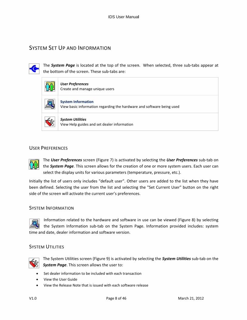
M SET UP A
he System Pahe bottom of
User PCreat
SysteView
SystemView
EFERENCES
he User Prefehe System Pagelect the disp
he list of userned. Selectine screen will
INFORMATIO
nformation rehe System Indate, dealer i
UTILITIES
he System Utystem Page. T
et dealer informiew the User Giew the Releas
AND INFOR
age is locatedthe screen. T
Preferences e and manage
m Informationbasic informat
m Utilities Help guides an
erences screege. This screelay units for v
rs only includng the user fractivate the c
ON
elated to the nformation suinformation a
ilities screen This screen al
mation to be inGuide se Note that is
IDS
Page 8
MATION
d at the top oThese sub‐tab
unique users
n tion regarding
nd set dealer in
en (Figure 7) ien allows for various param
des "default urom the list acurrent user’s
hardware anub‐tab on thand software
(Figure 9) is allows the use
ncluded with e
issued with ea
User Manual
8 of 46
of the screenbs are:
the hardware
nformation
s activated bthe creation
meters (tempe
user". Other and selecting s preferences
nd software ie System Paversion.
activated by sr to:
each transactio
ach software re
l
n. When sele
and software b
by selecting thof one or moerature, pres
users are addthe "Set Curs.
n use can beage. Informat
selecting the
on
elease
Mar
ected, three s
being used
he User Prefeore system ussure, etc.).
ded to the lisrrent User" b
e viewed (Figution provided
System Utilit
ch 21, 2012
sub‐tabs appe
erences sub‐tsers. Each use
st when theybutton on the
ure 8) by seled includes: sy
ties sub‐tab o
ear at
tab on er can
y have e right
ecting ystem
on the

IDS User Manual
V1.0 Page 9 of 46 March 21, 2012
• Access other utilities
FIGURE 7: USER PREFERENCES SCREEN
FIGURE 8: INFORMATION SCREEN

IDS User Manual
V1.0 Page 10 of 46 March 21, 2012
FIGURE 9: SYSTEM UTILITIES SCREEN

IDS User Manual
V1.0 Page 11 of 46 March 21, 2012
VEHICLE ID AND SESSION MANAGEMENT
To activate applicable diagnostic tools, identify the vehicle by selecting the Vehicle Identification tab at the top of the screen.
START NEW SESSION
To automatically identify the vehicle, select the appropriate Data Link Connection sub‐menu under the “Start New Session” menu and click the Tick button (Figure 10).
FIGURE 10: START NEW SESSION MENU

IDS User Manual
V1.0 Page 12 of 46 March 21, 2012
MANUAL VEHICLE ENTRY
Manual Vehicle Entry is also available if the vehicle cannot be identified through the automatic Vehicle identification process. To manually identify the vehicle, select the “Manual Vehicle Entry” sub‐menu under the “Start New Session” menu and follow the on screen instructions (Figure 11) and pick a vehicle model from the options shown in Figure 12. The vehicle’s Powertrain Control Module (PCM) must then be identified as shown in Figure 13 using any one of the following identifiers:
• Part Number • Calibration Number • Tear tag Number
Once the PCM is identified, the Toolbox will be populated with applicable diagnostic tools and service functions.
FIGURE 11: MANUAL VEHICLE ENTRY SCREEN

IDS User Manual
V1.0 Page 13 of 46 March 21, 2012
FIGURE 12: MANUAL VEHICLE LIST
FIGURE 13: VEHICLE IDENTIFICATION SCREEN

IDS User Manual
V1.0 Page 14 of 46 March 21, 2012
VEHICLE SPECIFICATION
To view the vehicle’s attributes and specifications, select the Vehicle Specification sub‐tab on the Vehicle Identification tab (Figure 14).
FIGURE 14: VEHICLE SPECIFICATION
LOG VIEWER
Select the Log Viewer sub‐tab to view logged session information. Session information includes vehicle information, tool use, test data and test results as shown in Figure 15.
The following actions are provided for viewing logged information:
Menu Context Menu: Print Screen, Print Items, Print Filtered Items
Select Item Types Select the types of information to view in the Log Viewer.

IDS User Manual
V1.0 Page 15 of 46 March 21, 2012
FIGURE 15: LOG VIEWER SUB‐TAB
CLOSE SESSION
To end a diagnostic session, select the Close Session sub‐tab on the Vehicle Identification tab. Three options are available as shown in (Figure 16):
• “Hold (saves recordings)” – Saves the current session for future use. Up to twenty sessions can be placed on hold indefinitely.
• “Complete (deletes recordings)” – Saves a minimal amount of the vehicle information • “Delete (deletes session)” – Deletes the session completely from the PC. Deleted sessions cannot be
restored.

IDS User Manual
V1.0 Page 16 of 46 March 21, 2012
FIGURE 16: CLOSE SESSION SUB‐TAB
RESTORING A VEHICLE SESSION
To restore a vehicle session marked as “Hold” or “Complete”, select the Vehicle Identification tab, select the Previous Sessions Menu Item and then select a session from the available list (Figure 17 and Figure 18). Sessions listed under "Held Sessions" will include saved data recordings. Sessions listed under "Completed Sessions" will include vehicle information, but not recordings (Figure 18).
The following actions are provided for managing saved sessions:
Menu Context Menu: Print Screen, Select a Printer and Print
Select Multiple Sessions Selects multiple sessions
Delete Deletes the selected session(s)
Archive Session Saves the selected session to permanent storage

V1.0
RestoResto
UploaCopie
Sort SSorts
Back Step b
RecovRecov
Tick Re‐ac
ore Session ore a saved veh
ad Session es a saved sessi
Session List the sessions b
back to previou
ver ver a previousl
tivated a selec
IDS
Page 1
hicle session
ion to an exter
y VIN, Vehicle
us screen or m
y deleted sess
cted session
FIGURE 17: ACCE
User Manual
17 of 46
rnal storage loc
Model, Repair
menu
ion
ESSING PREVIOUS
l
cation
r Order numbe
S SESSIONS
Mar
er and/or date.
ch 21, 2012
.

IDS User Manual
V1.0 Page 18 of 46 March 21, 2012
FIGURE 18: SELECTING A PREVIOUS SESSION
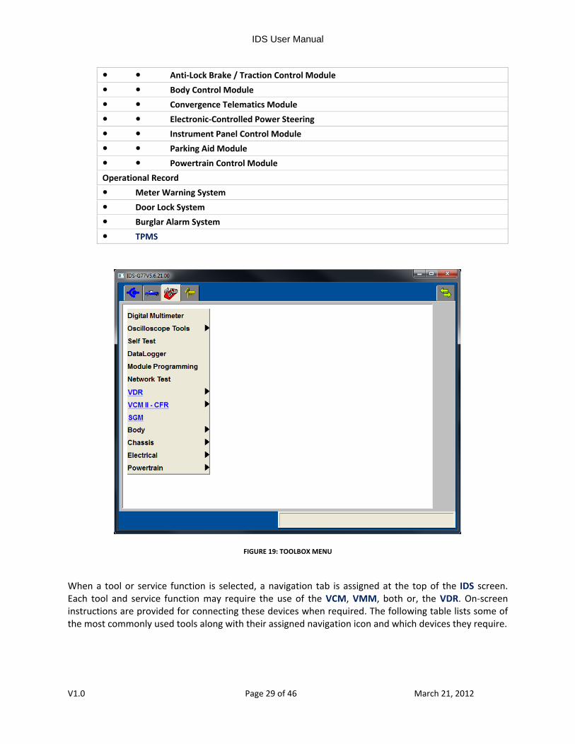
TOOLBOX
The Toolbox tab provides access to a number of diagnostic tools and service functions as shown in Figure 19. Tools displayed under this tab will only be shown if they are applicable to the identified Vehicle. For specific tool information please refer to technical Training web courses
(see the training resources listed in the Application Overview section, found on page 1. The following is a comprehensive list of sub‐menus, diagnostic tools and service functions as organized in the Toolbox menu as of IDS version R77 (this list continues to grow and evolve to support new vehicle technologies):
Digital Multi‐Meter Oscilloscope Tools Oscilloscope Oscilloscope with Hookups COP Stress Test Alternator Ripple Test
Variable Cam Timing (6 Cylinder) Intake Only (IPS#2 or VCT)

IDS User Manual
V1.0 Page 19 of 46 March 21, 2012
(VRS) (CMP) Sensors (2 wire)
Hall Effect CMP Sensors (3 wire) Variable Cam Timing (8 Cylinder) Dual Equal DEPS PCM Driver Test Escape PCM Driver Test for TSB 09‐02‐06 PCM Ignition Coil Driver Test PCM Injector Driver Test Diesel Cam Timing
Driver on Coil Ignition TestSelf‐Test Vehicle Statement Of Health DataLogger Module Programming Network Test Module Serial Number Module Identification VDR
Setup Upload/Playback
VCM II ‐ CFR Setup Upload/Playback
SGM Body Security
Interior Scan Test Keyless PATS Functions Factory Keyless Entry Code Keyfob Training Remote Keyless Entry Keyless Entry Keypad Code Reset Remote Start Learn Keys
TBM SIM RAV_ID Reset TBM Password Reset security ID ABS Configuration Reset Expansion ID Immobilizer PATS

IDS User Manual
V1.0 Page 20 of 46 March 21, 2012
Restraints
Delete Crash Recorder Power Seat Calibration Passenger System Reset Passenger Zero Seat Weight Test Passenger Seat Weight Sensor ReZero Passenger Airbag Deactivation Switch Airbag Resistance Check Beltminder Enable/Disable
EATC Operation Check Service Functions TBM Transit Mode CCMii Sensor Alignment PROXI Alignment CEI Lock Configuration Driver’s Door Module Driver Window Motor Test Passenger’s Door Module
Passenger Window Motor Test Rear Gate/Trunk Module Clear Self‐learning Data Camera Alignment Track Key Configuration Front Wiper Alignment TPMS Functions Sensor Learn Routine
Workshop test Body Control Module Service Functions BMS Reset RVC Configuration GEM Replacement of GEM Remote Keyless Entry Maintenance Information Power Seats
Driver’s Seat Module VSM Service Functions Burglar Service Functions Special Ignition ON Reset maintenance lamp Maintenance revision status

IDS User Manual
V1.0 Page 21 of 46 March 21, 2012
RCM Calibration
BCM/GEM Programmable Parameters Special Ignition ON Convergence Telematics Module PROXI Alignment EATC Motor’s end of travel learning. DEPS
PROXI Alignment Calibrate Steering Angle Sensor SWS Calibration
Chassis Braking ABS Service Bleed ABS Depressurizing/Brake Bleed ABS TPMS reset.
TPMS reset after ABS module replacement PBM Assembly Check Inclination Sensor Calibration Maintenance mode Static Apply Clear stored clutch engagement point Module Configuration
Component Checks Datalogger ABS reset and configuration. EPB calibration. Calibrate the emergency release. Calibrate the EPB function test. Calibrate a new EPB module. Calibrate the longitudinal acceleration sensor. BleedMASTER
ESP sensor calibration Configure All Three Sensors Together. Configure the lateral acceleration sensor. Configure the longitudinal acceleration sensor. Configure the pressure sensor. Configure Both the Yaw Rate Sensor and the Lateral Acceleration Sensors.

IDS User Manual
V1.0 Page 22 of 46 March 21, 2012
Configure the yaw rate sensor.
Variant and VIN Data Learning Procedure Pressure Sensor Calibration Configure the steering angle sensor. Reset Pressure Sensor Offset Calibrate Longitudinal Acceleration Sensor Enable/Disable hill launch assist . Calibrate Longitudinal Acceleration Sensor Inhibit longitudinal accelerometer monitoring
Module Initialization G Sensor Calibration IVD Initialization Sequence Read the ECU serial number. Read the sensor cluster serial number. Service Routine Steering angle sensor calibration Calibrate Steering Angle Sensor Auxiliary vehicle ID reset
Learn the vehicle variant and VIN data. Wheel speed sensor test Left Front Wheel Speed Sensor Test Right Rear Wheel Speed Sensor Test Left Rear Wheel Speed Sensor Test Right Front Wheel Speed Sensor Test Zero Speed Test ABS
PROXI Alignment Calibrate Longitudinal Acceleration Sensor Valve Calibration Suspension Ride Height Calibration Pneumatic Test Accurate Trim Test Wiggle Test Component Checks
EPS Neutral Position Setting Calibrate Steering Angle Sensor PDC Reset ABS/DSC Sensor Initialization

IDS User Manual
V1.0 Page 23 of 46 March 21, 2012
TPMS DTC Reset
Readout/Programming of Chassis Parameters Steering EPS Calibrate Steering Angle Sensor Configure the steering column assembly. Configure the intermediate shaft. Pull Drift Compensation Straight Ahead Adaption Angle Reset
Steering Rack Limiter Configuration PDC Enable/Disable EPS Steering Angle Calibration Replacement ABS Steering Wheel Position Sensor Calibration 4WD/ AWD Coupling Calibration Data Writing
Electrical Parking Aid Switch Test
Charging System Test Courtesy Lamp Relay Delayed Accessory Relay Radar Sensor Calibration Audio ACM AM Antenna Reception Sensitivity Test audio configuration
Infotainment Display Test Microphone Test Monotones Test Rear Tones Test ACM Security Bypass Test Audio Speaker Walk around Test Tones Test Touchscreen Exterior Lighting
Component Checks Headlamp Alignment AFS HID headlamps Headlamp Auto Leveling Sensor Re‐zero Procedure

IDS User Manual
V1.0 Page 24 of 46 March 21, 2012
Headlight Zero‐set
Auto Leveling Sensor Service Functions Car Mode Disable GDM VIN Show GEM configuration Module Configuration IMRCM PAD Switch
EPB Navigation Parameter reset/configuration IMRCM EPB BCMii Clear crash data memory. Parking Aid Trailer Module
FCDIM Keycode Reset WMM Calibration Rmode Rebalance Reactivation Washer / Wiper Component Checks Windshield Wiper Test
Rear Window Wiper Test CAN Bus Fault Test Instrument Cluster Gauge Test Button Test Illumination Test Multifunction Output Test Input and Data Test Cluster Function Test
Tachometer PROXI Alignment Message Center Default Language Odometer Programming Passenger Airbag Enable/Disable Supplemental Heater

IDS User Manual
V1.0 Page 25 of 46 March 21, 2012
FFH
FFH Unlock Utility FFH SelfTest and Prefill Utility FFH Start Heater Utility Prime the fuel system. FFPH FFPH Conditions For Start‐up FFPH Heater Operation FFPH Further Information
EAH EAH Further Information FFH Operation Check FFH Fuel Priming Rain Sensor Reset IC Service Functions LPSDM and RPSDM Service Function ICCM Aiming Adjustment BSM Radar Test
RVM Aiming Cruise Control CCM#1 Calibration RKE Touch Sensor Status Monitor PAM PROXI Alignment RCM
PROXI Alignment SOD‐L Module Reset SOD‐R Module Reset FSC Aiming
Powertrain Air Management EGR System Test
Turbocharger Test TURBO_FLUSH Turbo Boost Test VVT Test Fuel EVAP Test

IDS User Manual
V1.0 Page 26 of 46 March 21, 2012
Fuel Economy Test
Fuel System Test Low Pressure Test High Pressure Test Ignition Tools Ignition Test COP Stress Test Spark Duration PIDs Driver on Coil Ignition Test
Misfire Test Power Balance Relative Compression Engine Checks Transmission OBD Test Modes OBD Drive Cycle Mode 1 Powertrain Data Mode 6 On‐Board Test Results
Mode 8 – On‐Board device control Mode 9 – Vehicle Information Reset KAM PCM TCM ASM Service Functions Rear Driveshaft Balance ATC#1 Barcode Entry
Front Driveshaft Balance Automatic 4 wheel drive A/F (Fuel Ratio) Injector ID code A/C Test Engine Start Frequency MAF Correction DPD Replacement of the PCM
Clear Learning Value FFH Lockout Mode Reset DPF ETB/EGR Initialization Data Reset

IDS User Manual
V1.0 Page 27 of 46 March 21, 2012
Driveshaft Balance
PCM Calibration ID Number Misfire Check Electronic Throttle Control Readout/Correction of PCM Parameters Service Functions TCM PCM Reset the Powertrain Control Module Learned Values
DPF Manual Regeneration DPF Reset Clear EGR Adaptive Tables Clear Fuel Injector & HP Pump Adaptive Tables Reset / Clear Specified Function Misfire Monitor Neutral Profile Correction SCR System SCR System Emptying SCR System Refill Activation
SCR Parameter Reset SCR Visual Leak Check SCR Dosing Measurement Test Diesel Particulate Regeneration System DPF Parameter Reset DPF Filter Reset DPF Regeneration Suspension DPF Manual Regeneration
GPCM Calibration Synchronization Oxidation Catalyst Reset IQA WIF Reset Relearn Vehicle Data Cooling System Degas PCM Service Functions Reset Supply Pump Learned Values Resetting adaptive values
Transmission Neutral Position Learning Clearing of Learning Value Transmission Learning CVT Slope Sensor Calibration CVT Learning Value Setting

IDS User Manual
V1.0 Page 28 of 46 March 21, 2012
TCM Adaptive Learning
Clutch System Test Speed Sensor Test Transmission Solenoid Body IDN Clear Transmission Adaptive Tables Reset Transmission Tables Stop Use of Transmission Adaptive Halt Transmission Adaptive Learning Resume Transmission Adaptive Learning
TR Sensor Test Live Data Display TCM TCM Basic Setting Stall Line Pressure Test Transmission Speed Sensor Test Transmission Hydraulic Line Pressure Test Transmission Fluid Level Test Automatic Transmission PRNDL Display Test BSI Solenoid Test
Automatic Transmission Park Switch Test Transmission Characterization / Solenoid IDN Collect Diagnostic Information i‐stop Data Reset SCR System Urea Hose Leak Test Aborted urea injector test.
Aborted urea pump test. Cam Timing Learning Writing Presumptive Frequency of Starter Motor Activations
Mazda Vehicle Check‐up Blank Module Programming Install new module Anti‐Lock Brake / Traction Control Module Body Control Module Convergence Telematics Module
Electronic Air Temperature Controller Electronic‐Controlled Power Steering Instrument Panel Control Module Parking Aid Module Powertrain Control Module Reprogram module
IDS User Manual
V1.0 Page 29 of 46 March 21, 2012
Anti‐Lock Brake / Traction Control Module
Body Control Module Convergence Telematics Module Electronic‐Controlled Power Steering Instrument Panel Control Module Parking Aid Module Powertrain Control Module
Operational Record Meter Warning System
Door Lock System Burglar Alarm System TPMS
FIGURE 19: TOOLBOX MENU
When a tool or service function is selected, a navigation tab is assigned at the top of the IDS screen. Each tool and service function may require the use of the VCM, VMM, both or, the VDR. On‐screen instructions are provided for connecting these devices when required. The following table lists some of the most commonly used tools along with their assigned navigation icon and which devices they require.

IDS User Manual
V1.0 Page 30 of 46 March 21, 2012
Alternator Ripple Test Uses the oscilloscope tool to analyze alternator ripple. A useful tool for diagnosing problems with the charging system.
DataLogger Monitors selectable Electronic Control Unit (ECU) parameters (PIDs) through the vehicle communication network.
Digital Multi‐Meter Provides various multi‐meter functions, such as measurements of AC voltage, Vehicle Battery voltage, DC voltage, Resistance, Frequency, Period, Duty Cycle, and Pressure (Requires the VMM).
Fuel Economy Test Analyzes and tests the fuel economy of the vehicle.
Fuel System Test Tests the fuel system including the operation of injectors and pumps.
Ignition Test Analyzes the condition of the secondary ignition system by monitoring spark activity using capacitive pickups.
Oscilloscope A four channel oscilloscope for analyzing electrical signals.
Mode 6 On‐Board Test ResultsAccess the results of OBDII monitors.
Module Programming Reprograms and configures ECUs.
Network Test Analyzes and performs tests of the vehicle’s communications network by searching for all available ECUs.
PATS Functions Performs various tests and service functions related to the Passive Anti‐Theft System.
Power Balance Analyzes and displays the relative power contributed by each cylinder.

IDS User Manual
V1.0 Page 31 of 46 March 21, 2012
Relative Compression Analyzes and displays the relative compression achieved by each cylinder.
Reset KAM Clears learned values that an ECU has stored for adaptive systems.
Self‐Test Performs on‐board vehicle diagnostic routines and retrieves and clears Diagnostic Trouble Codes (). (i.e. All CMDTC’s, KOEO, KOER, etc).
SGM Generates and simulates ECU input signals to override sensors and verify ECU input signal acquisition.
VCM II CFR Setup Configures the CFR to monitor selected parameters and record the data during customer triggered events.
VCM II CFR Upload/PlaybackUploads customer recorded event data from a configured CFR to IDS for viewing and analyses.
VDR Setup Configures the VDR to monitor selected parameters and record the data during customer triggered events.
VDR Upload/Playback Uploads customer recorded event data from a configured VDR to IDS for viewing and analyses.

IDS User Manual
V1.0 Page 32 of 46 March 21, 2012
DEVICE SELECTION
The Device Selection tab (Figure 20) is available after the IDS application has used a VCM II at least once. The Device Selection tab will show a list of available VCM devices. The top two rows
in the device list will always be present and represent wired versions of the VCM and the VCM II. Wireless VCM II devices will be shown in the list below the top two rows if the VCM II wireless adapter is inserted into the IDS laptop.
FIGURE 20: DEVICE SELECTION TAB

IDS User Manual
V1.0 Page 33 of 46 March 21, 2012
ESTABLISHING A CONNECTION TO A WIRED VCM
To establish a connection to a wired VCM, simply attach the VCM to your IDS PC using a USB cable.
Once a connection has been made to the VCM, the status of the device will display the word “Connected”, as shown in Figure 21.
NOTE: It may take 10 to 20 seconds for a wired connection to be established between your IDS PC and a VCM device.
FIGURE 21: WIRED VEHICLE COMMUNICATIONS MODULE CONNECTION

V1.0
ESTABLIS
To establi
1. In2. St
Nus
3. Se4. Se
Nto
5. Clti
6. Se
Once a co“Connecte
NOTE: It m
SHING A CON
ish a connect
nsert a D‐Linktart IDS.
NOTE: It may tsed for the fir
elect the IDS elect a wirele
WARNING may disru
OTE: If you seo update your s
lick the “Wireme. elect the blue t
onnection hased”, as shown i
may take 30 sec
NNECTION TO
ion to a wirel
k wireless ada
take some timrst time.
Device Selectess VCM II wh
G: Verify the pt other VC
lect a VCM II wsoftware.
less Default” c
tick.
been made n Figure 23.
conds to one m
IDS
Page 3
O A WIRELES
less VCM II, fo
apter into you
me for IDS to
tion tab hose status is
VCM II seriaM II's and ri
whose softwar
check box to
to the wirele
minute for a co
User Manual
34 of 46
SS VCM II
ollow the ste
ur IDS laptop.
o configure th
“Detected”, a
al number bisk personal
re does not m
have IDS auto
ess VCM II, th
nnection to be
l
ps below.
he D‐Link ada
as shown in F
belongs to yo injury.
atch IDS you w
omatically con
he status of t
e established to
Mar
pter when th
Figure 22.
our device.
will be prompt
nect to the se
the device wi
o a wireless VC
ch 21, 2012
he adapter is
Failure to do
ted with instru
elected VCM I
ill display the
CM II.
being
o so
uctions
I each
word

IDS User Manual
V1.0 Page 35 of 46 March 21, 2012
FIGURE 22: WIRELESS VEHICLE COMMUNICATIONS MODULE SELECTION
FIGURE 23: A WIRELESSLY‐CONNECTED VEHICLE COMMUNICATIONS MODULE

IDS User Manual
V1.0 Page 36 of 46 March 21, 2012
ACRONYMS ABS Anti‐Lock Brake / Traction Control Module
A/C Air conditioning
ACM Audio Control Module
AFS Adaptive Front Lighting System
ASM Auto Shift Manual
ATC#1 Active Torque Coupling
AWD All‐Wheel Drive
BCM Battery Control Module
BCMii Body Control Module
BMS Battery Monitoring System
BSI Brake Shift Interlock
BSM Blind Spot Monitoring
CAN Controller Area Network
CCM#1 Cruise Control Module
CCMii Cruise Control Module
CEI Configurable Engine Immobilizer
CFR Customer Flight Recorder
CMP Camshaft Position Sensor
COP Coil On Plug
CTM Convergence Telematics Module
DEPS Dual Equal Phase Shifting
DLC Data Link Connector
DPD Diesel Particulate Defuser
IDS User Manual
V1.0 Page 37 of 46 March 21, 2012
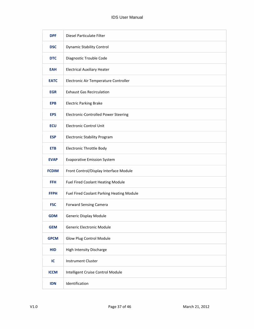
DPF Diesel Particulate Filter
DSC Dynamic Stability Control
DTC Diagnostic Trouble Code
EAH Electrical Auxiliary Heater
EATC Electronic Air Temperature Controller
EGR Exhaust Gas Recirculation
EPB Electric Parking Brake
EPS Electronic‐Controlled Power Steering
ECU Electronic Control Unit
ESP Electronic Stability Program
ETB Electronic Throttle Body
EVAP Evaporative Emission System
FCDIM Front Control/Display Interface Module
FFH Fuel Fired Coolant Heating Module
FFPH Fuel Fired Coolant Parking Heating Module
FSC Forward Sensing Camera
GDM Generic Display Module
GEM Generic Electronic Module
GPCM Glow Plug Control Module
HID High Intensity Discharge
IC Instrument Cluster
ICCM Intelligent Cruise Control Module
IDN Identification

IDS User Manual
V1.0 Page 38 of 46 March 21, 2012
IPC Instrument Panel Control Module
IPS Input Shaft Speed
IPS#2 Intake Phase Shifting
IQA Injector Quantity Adjustment
IDS Integrated Diagnostic System
IMRCM Intake Manifold Runner Control Monitor
ISM Interior Scanning Module
IVD Interactive Vehicle Dynamics
KAM Keep Alive Memory
LPSDM Left Power Sliding Door Module
MAF Mass Air Flow
OBD On‐Board Diagnostics
PAD Passenger Airbag Deactivation Warning
PAM Parking Aid Module
PATS Passive Anti‐Theft System
PBM Park Brake Control Module
PC Personal Computer
PCM Powertrain Control Module
PDC Pull Drift Compensation
PRNDL Selector lever position (PRND321)
RCM Restraint Control Module
RKE Remote Keyless Entry
RPSDM Right Power Sliding Door Module

IDS User Manual
V1.0 Page 39 of 46 March 21, 2012
RVC Rear Video Camera
RVM Rear Vehicle Monitoring
SCR Selective Catalytic Reduction
SGM Signal Generator Monitor
SOD‐L Side Obstacle Detection Control Module – Left
SOD‐R Side Obstacle Detection Control Module – Right
SWS Seat Weight Sensor
TBM Tracking and Blocking Module
TCM Transmission Control Module
TPMS Tire Pressure Monitoring System
TR Transmission range
TSB Technical Service Bulletin
USB Universal Serial Bus
VCM Vehicle Communication Module
VCT Variable Camshaft Timing
VDR Vehicle Data Recorder
VIN Vehicle Identification Number
VMM Vehicle Measurement Module
VSM Vehicle Security Module
VVT Variable Vane Turbo
WIF Water In Fuel
WMM Wiper Motor Module
4WD Four Wheel Drive

V1.0
SYMBO
Navigatio
Status Ico
System Pa
Vehicle Id
User Prefe
Log Viewe
LS (FUNCT
n Tabs
ons
age Sub‐tabs
dentification S
erences Butto
er Buttons
TIONAL GRO
Sub‐tabs
ons
IDS
Page 4
OUPS)
User Manual
40 of 46
l
Mar
ch 21, 2012

V1.0
Previous S
Tool Sub‐t
Paramete
Live Displ
Playback
Sessions Butt
tabs (Actual T
er Selection B
ay Buttons (A
Display Butto
ons
Tabs shown a
uttons (Actua
Actual Button
ons (Actual Bu
IDS
Page 4
are tool‐depe
al Buttons sho
s shown are t
uttons shown
User Manual
41 of 46
ndant)
own are tool‐
tool‐dependa
are tool‐dep
l
‐dependant)
ant)
pendant)
Mar
ch 21, 2012

IDS User Manual
V1.0 Page 42 of 46 March 21, 2012
GLOSSARY OF SYMBOLS (ALPHABETICAL)
Add User buttonAdd a new user
Archive Session buttonSaves a session to permanent storage
Back buttonStep back to previous screen or menu
Cancel buttonCancel or close a statement or screen
Change User Preferences buttonChange user preferences
Clear buttonClears selected electronic control module parameters, display settings, captured data etc...
Close Session sub‐tabClose vehicle session
Data Capture buttonStarts capturing data, which can be saved and viewed in Playback Display.
DataLogger tabA diagnostic application that allows the user to select and monitor parameters (PIDs) through the vehicle communication network from the DLC.
Delete sub‐tabDeletes the selected session(s)
Delete User buttonDeletes a user
Device Selection tabSelect a Vehicle Communications Module

IDS User Manual
V1.0 Page 43 of 46 March 21, 2012
Diagnostic Test tabRepresents a general diagnostic tool or service function.
Digital Multi‐meter tabProvides various multi‐meter functions, such as measurements of AC voltage, Vehicle Battery voltage, DC voltage, Resistance, Frequency, Period, Duty Cycle, and Pressure (Requires the VMM).
Expand Signal View buttonExpands the display size of a selected electronic control module parameter.
Fuel Economy Test tabAnalyzes and tests the fuel economy of the vehicle.
Fuel System Test tabTests the fuel system including the operation of injectors and pumps.
Guided Diagnostic tabLists recommended diagnostic tools
Information buttonDisplay information related to the current screen
Live Display sub‐tabDisplay live data for selected electronic control module input and output parameters.
Load Parameters and Settings buttonLoad saved selection of electronic control module parameters and display settings.
Lock status iconThe operation being performed cannot be interrupted
Log Viewer sub‐tabView logged session information
Menu buttonContext sensitive pop‐up menu for general printing, navigating, logging data, configuring etc.
Module Programming tabReprograms and configures ECUs.
Move buttonMoves the display order of selected electronic control module input and output parameters.

V1.0
NetwoAnalyzavailab
OSC DDisabl
OSC EEnable
OscilloProvidsignals
ParamSelect
PlaybaView o
Plot FoDisplaParamgraphssizes.
RecordConfig
RecovRecov
ReducReduc
RestorRestor
Save PSave s
SelectSelect
ork Test zes and perfoble ECUs.
Disable e output state
nable e output state
oscope des a four‐chans, to assist in d
meter Selectionelectronic con
ack Display or replay a save
ormat Limits ays a pop‐up w
meters can be s. It also allo
ding Time gure the captur
ver er a previously
ce Signal View ces the display
re Session re a saved veh
Parameters anselected electro
t Item Types the types of in
IDS
Page 4
orms tests of
control. Contr
control. Contr
nnel oscilloscoiagnosis or ana
n ntrol module in
ed data record
and Rangeindow for chandisplayed as tws the config
re buffer durat
y deleted sessio
size of a select
icle session
d Settingsonic control m
nformation to v
User Manual
44 of 46
the vehicle’s
rollable param
ollable parame
ope tool that calysis (Require
nput and outpu
ding.
nging the graptext or plotteduration of trig
tion, pre‐trigge
on
ted electronic
odule paramet
view in the Log
l
communicatio
meters are deno
eters are deno
an be utilized es the VMM).
ut parameters
phical display pd over time inggers, limits, d
er time and po
control modul
ters and displa
g Viewer.
Mar
ons network b
oted by "#" nex
oted by "#" nex
by the users t
for monitoring
properties of a n linear graphsdisplay ranges
ost‐trigger time
le parameter.
ay settings.
ch 21, 2012
by searching
buxt to their nam
buxt to their nam
to monitor ele
subg and testing.
sub
buselected params, histograms and capture
bue.
bu
bu
bu
bu
bu
tabfor all
uttonme.
uttone.
tabectrical
b‐tab
b‐tab
uttonmeter. or bar buffer
utton
utton
utton
utton
utton
utton

V1.0
SelectSelect
Self TeProvidCodes
Set CuSet the
SGM Signal
Sort SSorts t
SystemDispla
SystemSet up
SystemSelect
SystemSet up
Tick Accep
ToolboLists a
TraininThe cu
UploaCopies
User PAdd an
t Multiple Sesss multiple sess
est des a list of m for the vehicle
urrent User e current user
Generator Mo
ession List the sessions by
m Informationy system infor
m Page p the system an
m Select a vehicle syste
m Utilities p the system an
pt a statement
ox vailable diagno
ng Mode urrent mode of
d Session s a saved sessio
Preferences nd remove use
IDS
Page 4
sionssions
odule Self Tese, (i.e. All CMD
onitor (Require
y VIN, Vehicle M
mation.
nd view inform
em or module
nd display user
or screen
ostic tools
f operation is “
on to an extern
ers and set pre
User Manual
45 of 46
st routines avaDTC’s, KOEO, KO
es the Vehicle M
Model, Repair
mation related t
for testing.
r information
“Training Mode
nal storage loc
ferences
l
ailable to retrOER, etc).
Measurement
Order number
to the system.
e”
cation
Mar
ieve and clear
Module).
r and/or date.
ch 21, 2012
bu
r Diagnostic T
bu
bu
sub
sub
sub
bu
status
bu
sub
utton
tabrouble
utton
tab
utton
b‐tab
tab
b‐tab
b‐tab
utton
tab
icon
utton
b‐tab

IDS User Manual
V1.0 Page 46 of 46 March 21, 2012
VCM status iconVehicle Communications Module is Connected
VCM II status iconVehicle Communications Module II is Connected
VCM II CFR Setup tabConfigures the VCM II CFR to monitor selected parameters and record the data during customer triggered events..
VCM II CFR Upload/Playback tabUploads customer recorded event data from a configured CFR to IDS for viewing and analyses.
VDR Vehicle Data Recorder
VDR Setup tabConfigures the VDR to monitor selected parameters and record the data during customer triggered events.
VDR Upload/Playback tab Uploads customer recorded event data from a configured VDR to IDS for viewing and analyses.
Vehicle Specification sub‐tabList vehicle attributes and specifications.
Vehicle Identification tabIdentify a vehicle
VMM status iconVehicle Measurement Module