iecex ex test report cover - emerson electric · iecex test report section 1 to be completed by...
TRANSCRIPT

.Page 1 of 34
ExTR Reference Number.............. : GB/BAS/ExTR10.0134/00
ExTR Free Reference Number...... : 09/0519
Complied by + signature (ExTL).... : R. Powney .................................................
Reviewed by + signature (ExTL) ... : M. Powney .................................................
Approved by + signature (ExCB)... : R. Sinclair .................................................
Date of issue................................. : 7 June 2010
Ex Certification Body (ExCB)......... : Baseefa
Address ........................................ : Rockhead Business Park, Staden Lane, Buxton, Derbyshire, UK, SK17 9RZ
Ex Testing Laboratory (ExTL)........ : Baseefa
Address ........................................ : Rockhead Business Park, Staden Lane, Buxton, Derbyshire, UK, SK17 9RZ
Applicant’s name .......................... : Emerson Process Management - Rosemount Analytical
Address ........................................ : 2400 Barranca Parkway, Irvine, California 92606, USA
Standards ..................................... : IEC 60079-0:2007 Edition 5, IEC 60079-11:2006 Edition 5
Test procedure.............................. : IECEx Scheme
Test Report Form No. ................... : ExTR Cover_1
TRF Originator.............................. :
Master TRF................................... : Dated 2006-08
Instructions for Intended Use of Cover Sheet: This document is to be compiled and reviewed by the ExTL, with the ExCB giving the final approval, or compiled by the ExCB without the involvement of the ExTL. It is to serve as the sole cover for an ExTR package, which may be comprised of a single ExTR document or multiple ExTR documents. This ExTR Cover is to be completed and attached to the completed ExTR package.
Copyright © 2006 International Electrotechnical Commission Scheme for Certification to Standards Relating to Equipment for use in Explosive Atmospheres (IECEx), Geneva, Switzerland. All rights reserved.
This publication may be reproduced in whole or in part for non-commercial purposes as long as the IECEx is acknowledged as copyright owner and source of the material. IECEx takes no responsibility for and will not assume liability for damages resulting from the reader's interpretation of the reproduced material due to its placement and context.
Test item description..................... :
Trademark .................................... :
Model/type reference .................... : Xmt
Manufacturer ................................ : Emerson Process Management - Rosemount Analytical
Address ........................................ : 2400 Barranca Parkway, Irvine, California 92606, USA
Code (e.g. Ex II T ) ............ : Ex ia IIC T4 Ga
IECEx Ex TEST REPORT COVER

.Page 2 of 34
Rating........................................... : Various

Page 3 of 34
Copy of Marking Plate
XMT-T-FF label used as an example.
Particulars: test item vs. test requirements
Classification of installation and use..................................... : portable / stationary / hand-held
Ingress protection ................................................................ : IP20 min
Rated ambient temperature range (°C) ................................. : -20°C to +50°C
General remarks: General product information: The Xmt is designed to convert an electrical signal from a remote sensor, or integral toroidal sensor (Xmt-T only) into a 4-20mA HART compatible signal. The apparatus consists of a printed circuit board, terminal facilities and a liquid crystal display and keypad, all housed in a plastic enclosure. The apparatus may be designated Xmt-A, Xmt-P, Xmt-C and Xmt-T. The Xmt-A and Xmt-P differ only in software. The suffixes -HT, -FF & -FI designate the following protocol compatibilities: HT HART FF Fieldbus FI FISCO Manufacturer’s Documents Document No. Sheets Document Title Issue Date 33633-00 1 & 2 Enclosure, Front Pipe Mount J 09-27-05 33634-00/01 1 & 2 Enclosure, Rear Pipe Mount L 09-10-04 33635-00 1 of 1 Cover, Panel Mount Enclosure H 03-28-08 33636-00 1 & 2 Enclosure, Panel Mount M 03-25-08 33670-01 1 – 4 Overlay, XMT D 01-10-07 33788-00 1 of 1 PCB, SoluComp XMT-A/P E 08-23-05 33831-02 1 of 1 Cover, PCB SoluComp XMT-T E 08-24-06 33831-00 1 of 1 Cover, PCB SoluComp XMT-A G 08-24-06 33870-00 1 of 1 PCB SoluComp XMT-C-HT B 08-23-05 33884-00 1 of 1 PCB, SoluComp XMT-T-HT B 08-23-06 33943-00 1 of 1 PCB, SoluComp, XMT-A/P-FF-FI A 06-02-05 33944-00 1 of 1 PCB, SoluComp XMT-C-FF-FI A 06-02-05 33945-00 1 of 1 PCB, SoluComp XMT-T-FF-FI B 03-14-06 33948-00 1 of 1 PCB, SoluComp XMT-A/P-HT, CPU C 12-09-05 33949-00 1 of 1 PCB, SoluComp XMT-C-HT B 12-09-05 33950-00 1 of 1 PCB, SoluComp XMT-T-HT A 12-09-05 70025-00 1 of 1 PCB, Fieldbus Square Card C 07-13-07 1700430 1 – 5 Certified Product Schematic, PCB, SoluComp XMT-
A/P-HT A 01-05-04
1700456 1 – 3 Certified Product Toroidal Snsr Mod 245 B 09-22-04

Page 4 of 34
Document No. Sheets Document Title Issue Date 1700459 1 of 1 Certified Product DWG Toroidal Sensor Model
225/226/228 B 04-10-03
1700460 1 of 1 Certified Product DWG Toroidal Sensor Model 222 B 02-02-04 1700461 1 – 3 Certified Product DWG Toroidal Sensor Model 242 D 04-10-03 1700465 1 of 1 Certified Product Assembly, PCB, SoluComp XMT-
A/P-HT A 01-22-04
1700496 1 of 1 Certified Product Schematic, PCB, SoluComp XMT-C-HT
A 01-05-04
1700513 1 of 1 Certified Product MOD XMT-A-HT-10 Xmtr IS (BAS) A 01-22-04 1700514 1 of 1 Certified Product MOD XMT-A-FF-10 Xmtr IS (BAS) A 10-06-04 1700515 1 of 1 Certified Product MOD XMT-A-HT-11 Xmtr IS (BAS) B 01-22-04 1700516 1 of 1 Certified Product MOD XMT-A-FF-11 Xmtr IS (BAS) B 10-06-04 1700517 1 of 1 Certified Product MOD XMT-P-HT-10 Xmtr IS (BAS) A 01-22-04 1700518 1 of 1 Certified Product MOD XMT-P-FF-10 Xmtr IS (BAS) A 10-06-04 1700519 1 of 1 Certified Product MOD XMT-P-HT-11 Xmtr IS (BAS) B 01-22-04 1700520 1 of 1 Certified Product MOD XMT-P-FF-11 Xmtr IS (BAS) B 10-06-04 1700522 1 of 1 Certified Product MOD XMT-C-FF-10 Xmtr IS (BAS) A 10-06-04 1700523 1 of 1 Certified Product MOD XMT-C-HT-11 Xmtr IS (BAS) B 01-22-04 1700524 1 of 1 Certified Product MOD XMT-C-FF-11 Xmtr IS (BAS) B 10-06-04 1700525 1 of 1 Certified Product MOD XMT-T-HT-10 Xmtr IS (BAS) A 01-22-04 1700526 1 of 1 Certified Product MOD XMT-T-FF-10 Xmtr IS (BAS) A 10-06-04 1700527 1 of 1 Certified Product MOD XMT-T-HT-11 Xmtr IS (BAS) B 01-22-04 1700528 1 of 1 Certified Product MOD XMT-T-FF-11 Xmtr IS (BAS) B 10-06-04 1700529 1 of 1 Certified Product Assembly, PCB, SoluComp XMT-C-
HT A 01-20-04
1700530 1 – 5 Certified Product Schematic, PCB, SoluComp XMT-T-HT
A 01-05-04
1700531 1 of 1 Certified Product Assembly, PCB, SoluComp XMT-T-HT
A 01-20-04
1700573 1 of 1 Certified Product MOD XMT-A-FI-10 Xmtr IS (BAS) A 10-06-04 1700574 1 of 1 Certified Product MOD XMT-A-FI-11 Xmtr IS (BAS) B 10-06-04 1700575 1 of 1 Certified Product MOD XMT-P-FI-10 Xmtr IS (BAS) A 10-06-04 1700576 1 of 1 Certified Product MOD XMT-P-FI-11 Xmtr IS (BAS) B 10-06-04 1700577 1 of 1 Certified Product MOD XMT-C-FI-10 Xmtr IS (BAS) A 10-06-04 1700578 1 of 1 Certified Product MOD XMT-C-FI-11 Xmtr IS (BAS) B 10-06-04 1700579 1 of 1 Certified Product MOD XMT-T-FI-10 Xmtr IS (BAS) A 10-06-04 1700580 1 of 1 Certified Product MOD XMT-T-FI-11 Xmtr IS (BAS) B 10-06-04 1700590 1 of 1 Certified Product Assembly, PCB, SoluComp XMT-
A/P-FF B 09-13-07
1700591 1 of 1 Certified Product Assembly, PCB, SoluComp XMT-A/P-FI
B 09-13-07
1700592 1 – 5 Certified Product Schematic, PCB, SoluComp XMT-A/P-FF-FI
A 10-06-04
1700593 1 of 1 Certified Product Assembly, PCB, SoluComp XMT-C-FF
A 11-01-05
1700594 1 of 1 Certified Product Assembly, PCb, SoluComp XMT-C-FI
A 11-01-05
1700595 1 – 5 Certified Product Schematic, PCB, SoluComp XMT-C-FF-FI
A 10-06-04
1700596 1 of 1 Certified Product Assembly, PCB, SoluComp XMT-T-FF
B 03-01-06
1700597 1 of 1 Certified Product Assembly, PCB, SoluComp XMT-T-FI
B 03-01-06
1700598 1 – 5 Certified Product Schematic, PCB, SoluComp XMT-T-FF-FI
B 11-06-06
9241577-00 1 of 1 Label, IS Baseefa XMT-A-HT C 02-19-10 9241578-00 1 of 1 Label, IS Baseefa XMT-A-FF C 02-19-10 9241579-00 1 of 1 Label, IS Baseefa XMT-P-HT C 02-19-10 9241580-00 1 of 1 Label, IS Baseefa XMT-P-FF C 02-19-10 9241581-00 1 of 1 Label, IS Baseefa XMT-C-HT C 02-19-10 9241582-00 1 of 1 Label, IS Baseefa XMT-C-FF C 02-19-10
Page 5 of 34
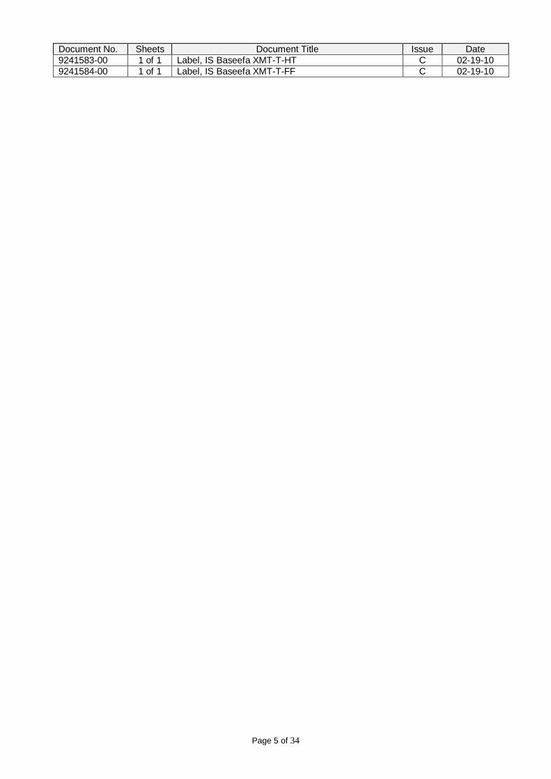
Document No. Sheets Document Title Issue Date 9241583-00 1 of 1 Label, IS Baseefa XMT-T-HT C 02-19-10 9241584-00 1 of 1 Label, IS Baseefa XMT-T-FF C 02-19-10

IECEx TEST REPORT Section 1
To be completed by ExCB
Page 6 of 34
ExTR Reference Number.............. : GB/BAS/ExTR10.0134/00
ExTR Free Reference Number...... : 09/0519
Complied by + signature (ExTL).... : R. Powney .................................................
Reviewed by + signature (ExTL) ... : M. Powney .................................................
Date of issue ................................ : 7 June 2010
Ex Testing Laboratory (ExTL) ....... : Baseefa
Address........................................ : Rockhead Business Park, Staden Lane, Buxton, SK17 9RZ, UK
Applicant’s name .......................... : Emerson Process Management - Rosemount Analytical
Address........................................ : 2400 Barranca Parkway, Irvine, California 92606, USA
Standard....................................... : IEC 60079-0:2007 Edition 5
Test procedure ............................. : IECEx Scheme
Test Report Form No. ................... : ExTR60079-0:2007-Baseefa
TRF Originator.............................. :
Master TRF .................................. : dated 2008-03
Instructions for Intended Use of Ex Test Report: This ExTR blank document is to be compiled and reviewed by the ExTL. The ExTR package in which this ExTR is incorporated (comprised of a single ExTR document or multiple ExTR documents) is to be accompanied by a single ExTR Cover Sheet, which is to be approved by the ExCB. ExTR Addendum(s) and/or ExTR Report of National Differences may also supplement this ExTR.
Copyright © 2006 International Electrotechnical Commission Scheme for Certification to Standards Relating to Equipment for use in Explosive Atmospheres (IECEx), Geneva, Switzerland. All rights reserved.
This publication may be reproduced in whole or in part for non-commercial purposes as long as the IECEx is acknowledged as copyright owner and source of the material. IECEx takes no responsibility for and will not assume liability for damages resulting from the reader's interpretation of the reproduced material due to its placement and context.
Possible test case verdicts:
- test case does not apply to the test object .................………: N / A
- test object does meet the requirement .......................………: Pass
General remarks: The tests results presented in this report relate only to the object tested. This report shall not be reproduced except in full without the written approval of the testing laboratory. "(see Attachment #)" refers to additional information appended to the report. "(see appended table)" refers to a table appended to the report. Throughout this report a point is used as the decimal separator.
IECEx TEST REPORT IEC 60079
Electrical equipment for explosive gas atmospheres Part 0: General requirements

IECEx TEST REPORT Section 1
To be completed by ExCB
Page 7 of 34
ExTR: GB/BAS/ExTR10.0134/00 IEC 60079-0:2007 Edition 5 Clause Requirement – Test Result – Remark Verdict
1 SCOPE The Xmt is within the scope of IEC 60079-0:2007 and IEC 60079-11:2006. Pass
2 NORMATIVE REFERENCES
3 TERMS AND DEFINITIONS
4 EQUIPMENT GROUPING
4.1 Group I Not applicable. N/A
4.2 Group II The Xmt is intended for use in a Group IIC atmosphere. Pass
4.3 Group III Not in scope. N/A
4.4 Equipment for a particular explosive atmosphere See clause 4.2. N/A
5 TEMPERATURES
5.1 Environmental influences
5.1.1 Ambient temperatures
The Xmt has a Temperature Classification of T4 and an ambient temperature range of -20°C to +50°C. This is clearly marked on the certification label.
Pass
5.1.2 External source of heating or cooling See clause 5.1.1 Pass
5.2 Service temperature Not applicable. N/A
5.3 Maximum surface temperature
5.3.1 Determination of maximum surface temperature
The maximum surface temperature does not exceed the limit for T4 in a +50°C ambient. Pass
5.3.2 Limitation of maximum surface temperature
5.3.2.1 Group I electrical equipment Not applicable. N/A
5.3.2.2 Group II electrical equipment The maximum surface temperatures do not exceed the maximum permitted limits. Pass
5.3.2.3 Group III electrical equipment
5.3.2.3.1 Maximum surface temperature determined without a dust layer Not in scope. N/A
5.3.2.3.2 Maximum surface temperature with respect to dust layers Not in scope. N/A
IECEx TEST REPORT Section 1
To be completed by ExCB
Page 8 of 34
ExTR: GB/BAS/ExTR10.0134/00 IEC 60079-0:2007 Edition 5 Clause Requirement – Test Result – Remark Verdict
5.3.3 Small component temperature for Group I or Group II electrical equipment
See clause 5.3.2.2. Pass
6 REQUIREMENTS FOR ALL ELECTRICAL EQUIPMENT
6.1 General The Xmt complies with the requirements of IEC 60079-0:2007 and IEC 60079-11:2006. Pass
6.2 Mechanical strength of equipment Excluded by IEC 60079-11:2006. N/A
6.3 Opening times Excluded by IEC 60079-11:2006. N/A
6.4 Circulating current Excluded by IEC 60079-11:2006. N/A
6.5 Gasket retention Excluded by IEC 60079-11:2006. N/A
6.6 Electromagnetic and ultrasonic energy radiating equipment
6.6.1 Radio frequency sources Not applicable. N/A
6.6.2 Lasers or other continuous wave sources Not applicable. N/A
6.6.3 Ultrasonic sources Not applicable. N/A
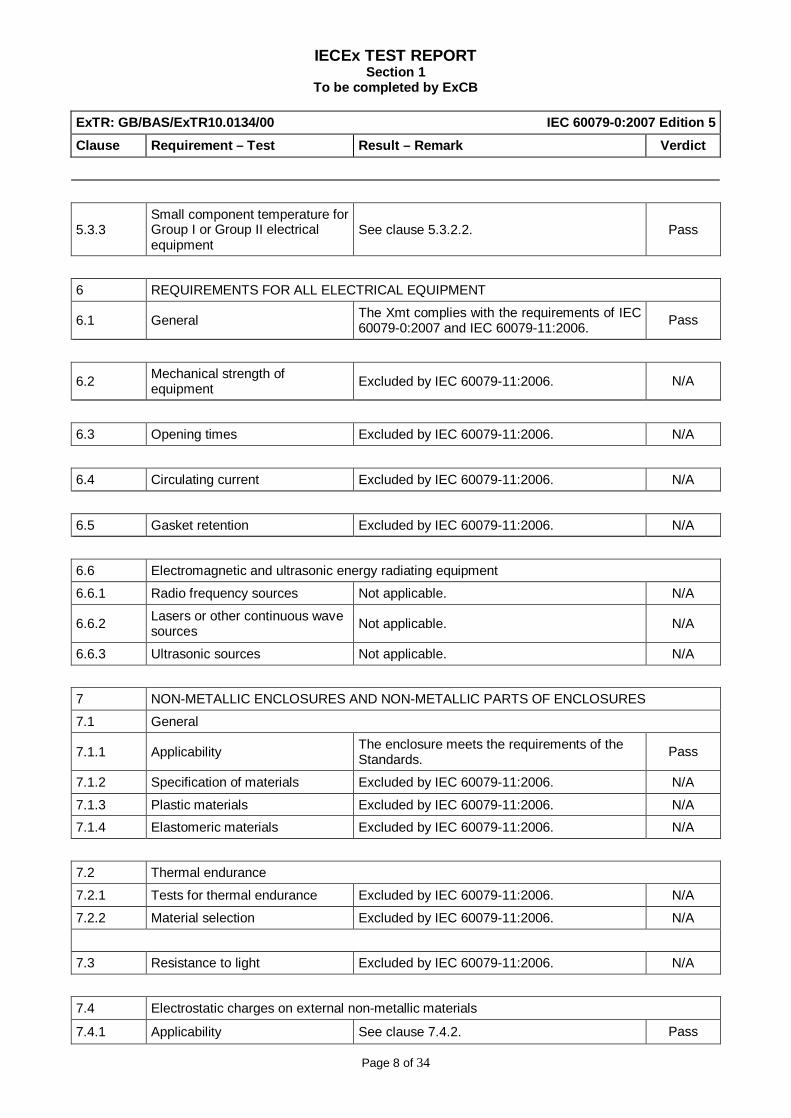
7 NON-METALLIC ENCLOSURES AND NON-METALLIC PARTS OF ENCLOSURES
7.1 General
7.1.1 Applicability The enclosure meets the requirements of the Standards. Pass
7.1.2 Specification of materials Excluded by IEC 60079-11:2006. N/A
7.1.3 Plastic materials Excluded by IEC 60079-11:2006. N/A
7.1.4 Elastomeric materials Excluded by IEC 60079-11:2006. N/A
7.2 Thermal endurance
7.2.1 Tests for thermal endurance Excluded by IEC 60079-11:2006. N/A
7.2.2 Material selection Excluded by IEC 60079-11:2006. N/A
7.3 Resistance to light Excluded by IEC 60079-11:2006. N/A
7.4 Electrostatic charges on external non-metallic materials
7.4.1 Applicability See clause 7.4.2. Pass

IECEx TEST REPORT Section 1
To be completed by ExCB
Page 9 of 34
ExTR: GB/BAS/ExTR10.0134/00 IEC 60079-0:2007 Edition 5 Clause Requirement – Test Result – Remark Verdict
7.4.2 Avoidance of a build-up of electrostatic charge on Group I or Group II electrical equipment
The enclosure is fabricated from Lexan and is assessed to have a surface resistance in excess of 1GΩ. The front panel (liquid crystal display window and keypad) has a ground plane ≤0.2mm from the front and back – the transparent section, provided for the display, is of laminate construction with the central plane being conductive and is electrically connected to the rest of the internal ground plane.
Pass
7.4.3 Avoidance of a build-up of electrostatic charge on equipment for Group III
Not in scope. N/A
7.5 Threaded holes Excluded by IEC 60079-11:2006. N/A
8 METALLIC ENCLOSURES AND METALLIC PARTS OF ENCLOSURES
8.1 Material Composition
8.1.1 Group I Not applicable. N/A
8.1.2 Group II Not applicable. See clause 7.4.2. N/A
8.1.3 Group III Not in scope. N/A
8.2 Threaded Holes Excluded by IEC 60079-11:2006. N/A
9 FASTENERS
9.1 General Excluded by IEC 60079-11:2006. N/A
9.2 Special fasteners Excluded by IEC 60079-11:2006. N/A
9.3 Holes for special fasteners Excluded by IEC 60079-11:2006. N/A
9.3.1 Thread engagement Excluded by IEC 60079-11:2006. N/A
9.3.2 Tolerance and clearance Excluded by IEC 60079-11:2006. N/A
9.3.3 Hexagon socket set screw Excluded by IEC 60079-11:2006. N/A
10 Interlocking devices Excluded by IEC 60079-11:2006. N/A
11 Bushings Excluded by IEC 60079-11:2006. N/A
12 Materials used for cementing Excluded by IEC 60079-11:2006. N/A
13 EX COMPONENTS

IECEx TEST REPORT Section 1
To be completed by ExCB
Page 10 of 34
ExTR: GB/BAS/ExTR10.0134/00 IEC 60079-0:2007 Edition 5 Clause Requirement – Test Result – Remark Verdict
13.1 General
The Fieldbus Communications Board (-FF / -FI versions only) is component certified under BAS01ATEX1385U and meets the requirements of Annex B.
Pass
13.2 Mounting The Fieldbus Communications Board (-FF / -FI versions only) is securely mounted on the PCB within the enclosure.
Pass
13.3 Internal mounting Not applicable. See clause 13.1. N/A
13.4 External mounting Not applicable. See clause 13.2. N/A
14 CONNECTION FACILITIES AND TERMINAL COMPARTMENTS
14.1 General Excluded by IEC 60079-11:2006. N/A
14.2 Termination compartment Excluded by IEC 60079-11:2006. N/A
14.3 Type of protection Excluded by IEC 60079-11:2006. N/A
14.4 Creepage and clearance Excluded by IEC 60079-11:2006. N/A
15 CONNECTION FACILITIES FOR EARTHING OR BONDING CONDUCTORS
15.1 Equipment requiring earthing Excluded by IEC 60079-11:2006. N/A
15.1.1 Internal Excluded by IEC 60079-11:2006. N/A
15.1.2 External Excluded by IEC 60079-11:2006. N/A
15.2 Equipment not requiring earthing Excluded by IEC 60079-11:2006. N/A
15.3 Size of conductor connection Excluded by IEC 60079-11:2006. N/A
15.4 Protection against corrosion Excluded by IEC 60079-11:2006. N/A
15.5 Secureness of electrical connection Excluded by IEC 60079-11:2006. N/A
16 ENTRIES INTO ENCLOSURES
16.1 General Excluded by IEC 60079-11:2006. N/A
16.2 Identification of entries Excluded by IEC 60079-11:2006. N/A
IECEx TEST REPORT Section 1
To be completed by ExCB
Page 11 of 34
ExTR: GB/BAS/ExTR10.0134/00 IEC 60079-0:2007 Edition 5 Clause Requirement – Test Result – Remark Verdict
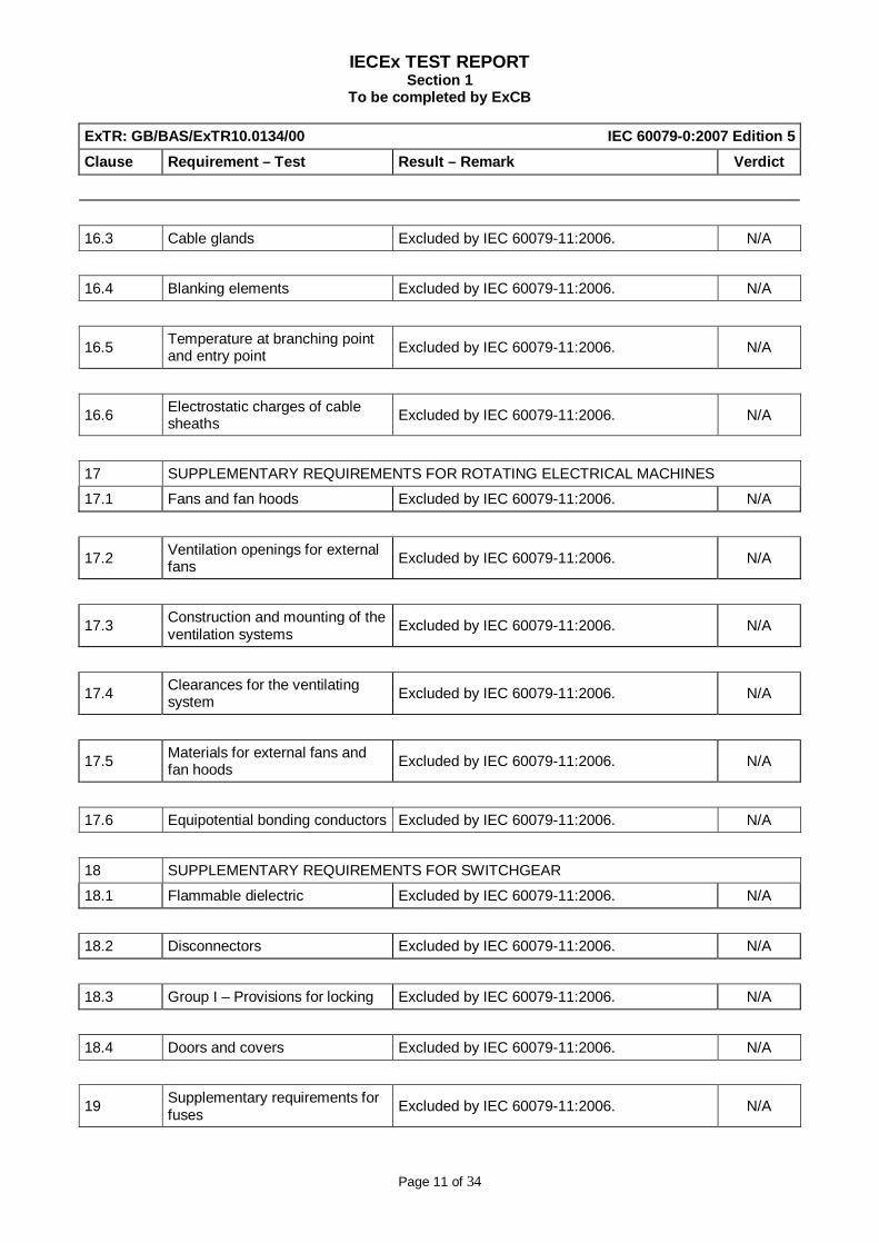
16.3 Cable glands Excluded by IEC 60079-11:2006. N/A
16.4 Blanking elements Excluded by IEC 60079-11:2006. N/A
16.5 Temperature at branching point and entry point Excluded by IEC 60079-11:2006. N/A
16.6 Electrostatic charges of cable sheaths Excluded by IEC 60079-11:2006. N/A
17 SUPPLEMENTARY REQUIREMENTS FOR ROTATING ELECTRICAL MACHINES
17.1 Fans and fan hoods Excluded by IEC 60079-11:2006. N/A
17.2 Ventilation openings for external fans Excluded by IEC 60079-11:2006. N/A
17.3 Construction and mounting of the ventilation systems Excluded by IEC 60079-11:2006. N/A
17.4 Clearances for the ventilating system Excluded by IEC 60079-11:2006. N/A
17.5 Materials for external fans and fan hoods Excluded by IEC 60079-11:2006. N/A
17.6 Equipotential bonding conductors Excluded by IEC 60079-11:2006. N/A
18 SUPPLEMENTARY REQUIREMENTS FOR SWITCHGEAR
18.1 Flammable dielectric Excluded by IEC 60079-11:2006. N/A
18.2 Disconnectors Excluded by IEC 60079-11:2006. N/A
18.3 Group I – Provisions for locking Excluded by IEC 60079-11:2006. N/A
18.4 Doors and covers Excluded by IEC 60079-11:2006. N/A
19 Supplementary requirements for fuses Excluded by IEC 60079-11:2006. N/A
IECEx TEST REPORT Section 1
To be completed by ExCB
Page 12 of 34
ExTR: GB/BAS/ExTR10.0134/00 IEC 60079-0:2007 Edition 5 Clause Requirement – Test Result – Remark Verdict
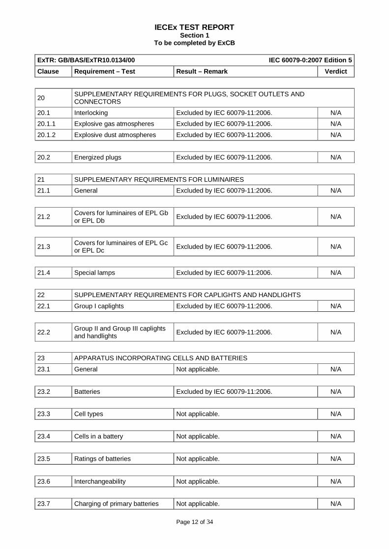
20 SUPPLEMENTARY REQUIREMENTS FOR PLUGS, SOCKET OUTLETS AND CONNECTORS
20.1 Interlocking Excluded by IEC 60079-11:2006. N/A
20.1.1 Explosive gas atmospheres Excluded by IEC 60079-11:2006. N/A
20.1.2 Explosive dust atmospheres Excluded by IEC 60079-11:2006. N/A
20.2 Energized plugs Excluded by IEC 60079-11:2006. N/A
21 SUPPLEMENTARY REQUIREMENTS FOR LUMINAIRES
21.1 General Excluded by IEC 60079-11:2006. N/A
21.2 Covers for luminaires of EPL Gb or EPL Db Excluded by IEC 60079-11:2006. N/A
21.3 Covers for luminaires of EPL Gc or EPL Dc Excluded by IEC 60079-11:2006. N/A
21.4 Special lamps Excluded by IEC 60079-11:2006. N/A
22 SUPPLEMENTARY REQUIREMENTS FOR CAPLIGHTS AND HANDLIGHTS
22.1 Group I caplights Excluded by IEC 60079-11:2006. N/A
22.2 Group II and Group III caplights and handlights Excluded by IEC 60079-11:2006. N/A
23 APPARATUS INCORPORATING CELLS AND BATTERIES
23.1 General Not applicable. N/A
23.2 Batteries Excluded by IEC 60079-11:2006. N/A
23.3 Cell types Not applicable. N/A
23.4 Cells in a battery Not applicable. N/A
23.5 Ratings of batteries Not applicable. N/A
23.6 Interchangeability Not applicable. N/A
23.7 Charging of primary batteries Not applicable. N/A

IECEx TEST REPORT Section 1
To be completed by ExCB
Page 13 of 34
ExTR: GB/BAS/ExTR10.0134/00 IEC 60079-0:2007 Edition 5 Clause Requirement – Test Result – Remark Verdict
23.8 Leakage Not applicable. N/A
23.9 Connections Not applicable. N/A
23.10 Orientation Not applicable. N/A
23.11 Replacement of cells or batteries Not applicable. N/A
23.12 Replaceable battery pack Not applicable. N/A
24 Documentation See list of manufacturer’s documents. Pass
25 Compliance of prototype or sample with documents Not applicable. N/A
26 TYPE TESTS
26.1 General Testing was deemed not necessary. N/A
26.2 Test configuration Not applicable. N/A
26.3 Tests in explosive test mixtures Not applicable. N/A
26.4 Tests of Enclosures
26.4.1 Order of tests
26.4.1.1 Metallic enclosures, metallic parts of enclosures and glass of parts of enclosures
Excluded by IEC 60079-11:2006. N/A
26.4.1.2 Non-metallic enclosures or non-metallic parts of enclosures Excluded by IEC 60079-11:2006. N/A
26.4.1.2.1 Group I electrical apparatus Excluded by IEC 60079-11:2006. N/A
26.4.1.2.2 Group II and Group III electrical apparatus Excluded by IEC 60079-11:2006. N/A
26.4.2 Resistance to impact Excluded by IEC 60079-11:2006. N/A
26.4.3 Drop test Not applicable. N/A
26.4.4 Acceptance criteria Excluded by IEC 60079-11:2006. N/A
26.4.5 Degree of protection (IP) by enclosures
26.4.5.1 Test procedure Excluded by IEC 60079-11:2006. N/A
26.4.5.2 Acceptance criteria Excluded by IEC 60079-11:2006. N/A
26.5 Thermal tests

IECEx TEST REPORT Section 1
To be completed by ExCB
Page 14 of 34
ExTR: GB/BAS/ExTR10.0134/00 IEC 60079-0:2007 Edition 5 Clause Requirement – Test Result – Remark Verdict
26.5.1 Temperature measurement
26.5.1.1 General Not applicable. N/A
26.5.1.2 Service temperature Not applicable. N/A
26.5.1.3 Maximum surface temperature Not applicable. N/A
26.5.2 Thermal shock test Excluded by IEC 60079-11:2006. N/A
26.5.3 Small component ignition test (Group I and Group II)
26.5.3.1 General Not applicable. N/A
26.5.3.2 Procedure Not applicable. N/A
26.5.3.3 Acceptance criteria Not applicable. N/A
26.6 Torque test for bushings Excluded by IEC 60079-11:2006. N/A
26.6.1 Test procedure Excluded by IEC 60079-11:2006. N/A
26.6.2 Acceptance criteria Excluded by IEC 60079-11:2006. N/A
26.7 Non-metallic enclosures or non-metallic parts of enclosures
26.7.1 General Excluded by IEC 60079-11:2006. N/A
26.7.2 Test temperatures Excluded by IEC 60079-11:2006. N/A
26.8 Thermal endurance to heat Excluded by IEC 60079-11:2006. N/A
26.9 Thermal endurance to cold Excluded by IEC 60079-11:2006. N/A
26.10 Resistance to light
26.10.1 Test procedure Excluded by IEC 60079-11:2006. N/A
26.10.2 Acceptance criteria Excluded by IEC 60079-11:2006. N/A
26.11 Resistance to chemical agents for Group I electrical equipment Excluded by IEC 60079-11:2006. N/A
26.12 Earth Continuity Excluded by IEC 60079-11:2006. N/A
26.13 Surface resistance test of parts of enclosures of non-metallic materials
Not applicable. N/A
26.14 Charging test
26.14.1 Introduction Not applicable. N/A
26.14.2 Principle of the test Not applicable. N/A
26.14.3 Samples and test apparatus Not applicable. N/A
IECEx TEST REPORT Section 1
To be completed by ExCB
Page 15 of 34
ExTR: GB/BAS/ExTR10.0134/00 IEC 60079-0:2007 Edition 5 Clause Requirement – Test Result – Remark Verdict
26.14.4 Ambient conditions Not applicable. N/A
26.14.5 Conditioning Not applicable. N/A
26.14.6 Determination of the most efficient charging method Not applicable. N/A
26.14.6.1 Method A: Rubbing with a pure polyamide cloth (figure 6) Not applicable. N/A
26.14.6.2 Method B: Rubbing with a cotton cloth (figure 6) Not applicable. N/A
26.14.6.3 Method C: Charging by influence with a d.c. high-voltage power supply (figure 8)
Not applicable. N/A
26.14.7 Assessment of discharge Not applicable. N/A
26.15 Measurement of capacitance Not applicable. N/A
26.15.1 Test procedure Not applicable. N/A
26.15.2 Acceptance criteria Not applicable. N/A
27 Routine tests Not applicable. N/A
28 MANUFACTURER'S RESPONSIBILITY
28.1 Conformity with the documentation Not applicable. N/A
28.2 Certificate Manufacturer’s responsibility. N/A
28.3 Responsibility for marking Manufacturer’s responsibility. N/A
29 MARKING
29.1 Location The certification label is legible and located on the exterior of the enclosure. Pass
29.2 General The marking meets the requirements of IEC 60079-0:2007 and IEC 60079-11:2006. Pass
29.3 Ex marking for explosive gas atmospheres See clause 29.2. Pass
29.4 Ex marking for explosive dust atmospheres Not applicable. See clause 4.2 and 4.3. N/A
29.5 Combined types of protection Not applicable. N/A
IECEx TEST REPORT Section 1
To be completed by ExCB
Page 16 of 34
ExTR: GB/BAS/ExTR10.0134/00 IEC 60079-0:2007 Edition 5 Clause Requirement – Test Result – Remark Verdict
29.6 Multiple types of protection Not applicable. N/A
29.7 Ga using two independent Gb types of protection Not applicable. N/A
29.8 Ex components Not applicable. N/A
29.9 Small equipment and small Ex components Not applicable. N/A
29.10 Extremely small equipment and small Ex components Not applicable. N/A
29.11 Warning markings The Xmt carries a warning that the plastic enclosure, excluding the front panel, must only be cleaned with a damp cloth.
Pass
29.12 Alternate marking of equipment protection levels
29.12.1 Alternate marking of type of protection for explosive gas atmospheres
Not applicable. N/A
29.12.2 Alternate marking of type of protection for explosive dust atmospheres
Not applicable. N/A
29.13 Cells and batteries Not applicable. N/A
29.14 Examples of marking Not applicable. N/A
30 INSTRUCTIONS
30.1 General A copy of the instructions, which meets the requirements of IEC 60079-0:2007, is kept on file.
Pass
30.2 Cells and batteries Not applicable. N/A
Annex A SUPPLEMENTARY REQUIREMENTS FOR CABLE GLANDS
A.1 General Excluded by IEC 60079-11:2006. N/A
A.2 Constructional requirements
A.2.1 Cable sealing Excluded by IEC 60079-11:2006. N/A

IECEx TEST REPORT Section 1
To be completed by ExCB
Page 17 of 34
ExTR: GB/BAS/ExTR10.0134/00 IEC 60079-0:2007 Edition 5 Clause Requirement – Test Result – Remark Verdict
A.2.2 Filling compounds Excluded by IEC 60079-11:2006. N/A
A.2.3 Clamping
A.2.3.1 General Excluded by IEC 60079-11:2006. N/A
A.2.3.2 Group II or III cable glands Excluded by IEC 60079-11:2006. N/A
A.2.4 Lead-in of cable
A.2.4.1 Sharp edges Excluded by IEC 60079-11:2006. N/A
A.2.4.2 Point of entry Excluded by IEC 60079-11:2006. N/A
A.2.5 Released by a tool Excluded by IEC 60079-11:2006. N/A
A.2.6 Fixing Excluded by IEC 60079-11:2006. N/A
A.2.7 Degree of protection Excluded by IEC 60079-11:2006. N/A
A.3 Type Tests
A.3.1 Tests of clamping of non-armoured and braided cables Excluded by IEC 60079-11:2006. N/A
A.3.1.1 Cable glands with clamping by the sealing ring Excluded by IEC 60079-11:2006. N/A
A.3.1.2 Cable glands with clamping by the filling compound Excluded by IEC 60079-11:2006. N/A
A.3.1.3 Cable glands with clamping by means of a clamping device Excluded by IEC 60079-11:2006. N/A
A.3.1.4 Tensile test Excluded by IEC 60079-11:2006. N/A
A.3.1.5 Mechanical strength Excluded by IEC 60079-11:2006. N/A
A.3.2 Tests of clamping of armoured cables
A.3.2.1 Tests of clamping where the armourings are clamped by a device within the gland
Excluded by IEC 60079-11:2006. N/A
A.3.2.1.1 Tensile test Excluded by IEC 60079-11:2006. N/A
A.3.2.1.2 Mechanical strength Excluded by IEC 60079-11:2006. N/A
A.3.2.2 Tests of clamping where the armourings are not clamped by a device within the gland
Excluded by IEC 60079-11:2006. N/A
A.3.3 Type test for resistance to impact
A.3.4 Test for degree of protection (IP) of cable entries Excluded by IEC 60079-11:2006. N/A
A.4 Marking

IECEx TEST REPORT Section 1
To be completed by ExCB
Page 18 of 34
ExTR: GB/BAS/ExTR10.0134/00 IEC 60079-0:2007 Edition 5 Clause Requirement – Test Result – Remark Verdict
A.4.1 Marking of cable glands Excluded by IEC 60079-11:2006. N/A
A.4.2 Marking of cable sealing rings Excluded by IEC 60079-11:2006. N/A
Annex B Requirements for Ex components The Fieldbus Communications Board (-FF / -FI versions only) meets the requirements of Annex B.
Pass
Annex C Example of Rig for resistance to impact test Not applicable. N/A
Annex D Introduction of an alternative risk assessment method Not applicable. N/A
Annex E Motors supplied by converters Not applicable. N/A
IECEx TEST REPORT Section 2
To be completed by ExCB
Page 19 of 34
ExTR Reference Number.............. : GB/BAS/ExTR10.0134/00
ExTR Free Reference Number...... : 09/0519
Complied by + signature (ExTL).... : R. Powney .................................................
Reviewed by + signature (ExTL) ... : M Powney .................................................
Date of issue ................................ : 7 June 2010
Ex Testing Laboratory (ExTL) ....... : Baseefa
Address........................................ : Rockhead Business Park, Staden Lane, Buxton, SK17 9RZ, UK
Applicant’s name .......................... : Emerson Process Management - Rosemount Analytical
Address........................................ : 2400 Barranca Parkway, Irvine, California 92606, USA
Standard....................................... : IEC 60079-11:2006, Fifth edition
Test procedure ............................. : IECEx Scheme
Test Report Form No. ................... : ExTR60079-11_Version1A
TRF Originator.............................. :
Master TRF .................................. : dated 2006-09
Instructions for Intended Use of Ex Test Report: This ExTR blank document is to be compiled and reviewed by the ExTL. The ExTR package in which this ExTR is incorporated (comprised of a single ExTR document or multiple ExTR documents) is to be accompanied by a single ExTR Cover Sheet, which is to be approved by the ExCB. ExTR Addendum(s) and/or ExTR Report of National Differences may also supplement this ExTR. Copyright © 2006 International Electrotechnical Commission Scheme for Certification to Standards Relating to Equipment for use in Explosive Atmospheres (IECEx), Geneva, Switzerland. All rights reserved.
This publication may be reproduced in whole or in part for non-commercial purposes as long as the IECEx is acknowledged as copyright owner and source of the material. IECEx takes no responsibility for and will not assume liability for damages resulting from the reader's interpretation of the reproduced material due to its placement and context.
Possible test case verdicts:
- test case does not apply to the test object ................. :N / A
- test object does meet the requirement ....................... :Pass
General remarks: The tests results presented in this report relate only to the object tested. This report shall not be reproduced except in full without the written approval of the testing laboratory. "(see Attachment #)" refers to additional information appended to the report. "(see appended table)" refers to a table appended to the report. Throughout this report a point is used as the decimal separator.
IECEx TEST REPORT IEC 60079
Explosive atmospheres – Part 11: Equipment protection by intrinsic safety "i"

IECEx TEST REPORT Section 3
To be completed by ExCB
Page 20 of 34
ExTR: GB/BAS/ExTR10.0134/00 IEC 60079-11:2006 5 Edition Clause Requirement – Test Result – Remark Verdict
1 SCOPE
2 NORMATIVE REFERENCES
3 DEFINITIONS
4 GROUPING AND CLASSIFICATION
5 LEVELS OF PROTECTION AND IGNITION COMPLIANCE
5.1 General The Xmt, coded Ex ia, meets the requirements of the applicable clauses of IEC 60079-11:2006.
Pass
5.2, 5.3, 5.4
Level of protection Refer to Appendix A.1 for details. Pass
5.5 Spark ignition compliance Refer to Appendix A.2 for details. Pass
5.6 Thermal ignition compliance
5.6.1 General Refer to Appendix A.3 for details. Pass
5.6.2 Temperature for small components
Refer to Appendix A.3.1 for details. Pass
5.6.3 Wiring within apparatus Refer to Appendix A.3.2 for details. Pass
5.6.4 Tracks on printed circuit boards Refer to Appendix A.3.3 for details. Pass
5.7 Simple apparatus Not applicable. N/A
6 APPARATUS CONSTRUCTION
6.1 Enclosures See clause 6.1.1. Pass
6.1.1 Apparatus complying with Table 5 The enclosure provides the electronics within with a degree of protection of at least IP20.
Pass
6.1.2 Apparatus complying with Annex F Not applicable. N/A
6.2 Facilities for connection of external circuits

IECEx TEST REPORT Section 3
To be completed by ExCB
Page 21 of 34
ExTR: GB/BAS/ExTR10.0134/00 IEC 60079-11:2006 5 Edition Clause Requirement – Test Result – Remark Verdict
6.2.1 Terminals A three-way terminal block is provided to allow connection to the loop and a suitable earth (which also grounds the front panel). Connections to the sensors are made via a twelve-way terminal block which is in excess of 90mm from the loop terminals.
Pass
6.2.2 Plugs and sockets Not applicable. N/A
6.2.3 Determination of maximum external inductance to resistance ratio (Lo/Ro) for resistance limited power source
See Appendix A.1. for details. Pass
6.2.4 Permanently connected cable Not applicable. N/A
6.3 Separation distances
6.3.1 Separation of conductive parts
6.3.1.1 Distances according to Table 5 All creepage, clearance and separation distances, where required, are in excess of the requirements of Table 5 of IEC 60079-11:2006. Additionally, the PCB is conformally coated with Humiseal or CTG TC-3285 both of which have a CTI in excess of the 100 required by IEC 60079-11:2006 for a peak voltage of 30V.
Pass
6.3.1.2 Distances according to Annex F Not applicable. N/A
6.3.2 Voltage between conductive parts Not applicable. N/A
6.3.3 Clearance See clause 6.3.1.1. Pass
6.3.4 Separation distances through casting compound
Not applicable. N/A
6.3.5 Separation distances through solid insulation
Not applicable. N/A
6.3.6 Composite separations Not applicable. N/A
6.3.7 Creepage distance See clause 6.3.1.1. Pass
6.3.8 Distance under coating See clause 6.3.1.1. Pass
6.3.9 Requirements for assembled printed circuit boards
See clause 6.3.1.1. Pass
6.3.10 Separation by earth screens Not applicable. N/A
6.3.11 Internal wiring Not applicable. N/A
6.3.12 Dielectric strength requirement It is assessed that the apparatus will withstand the 500Vrms test as described by clause 10.3 of IEC 60079-11:2006 due to the enclosure being plastic and therefore an insulator.
Pass
6.3.13 Relays Not applicable. N/A
6.4 Protection Against Polarity Reversal
A single diode provides protection against polarity reversal. Additionally, the loop terminals are clearly marked.
Pass

IECEx TEST REPORT Section 3
To be completed by ExCB
Page 22 of 34
ExTR: GB/BAS/ExTR10.0134/00 IEC 60079-11:2006 5 Edition Clause Requirement – Test Result – Remark Verdict
6.5 Earth conductors, connections and terminals
The earth terminal in the loop connection terminal block is considered suitable for purpose.
Pass
6.6 Encapsulation Not applicable. N/A
7 COMPONENTS ON WHICH INTRINSIC SAFETY DEPENDS
7.1 Rating of components Refer to Appendix A.4 for details.
7.2 Connectors for internal connections, plug-in cards and components
The internal connections are all factory made and are considered impossible to interchange with other connections. The Fieldbus Communications Board is mechanically secured to the main PCB by screws.
Pass
7.3 Fuses Not applicable. N/A
7.4 Primary and secondary cells and batteries
7.4.1 General The Xmt does not contain any cells or batteries N/A 7.4.2 Electrolyte leakage and ventilation Not applicable. See clause 7.4.1. N/A
7.4.3 Cell voltages Not applicable. See clause 7.4.1. N/A
7.4.4 Internal resistance of cell or battery
Not applicable. See clause 7.4.1. N/A
7.4.5 Batteries in apparatus protected by other means of protection
Not applicable. See clause 7.4.1. N/A
7.4.6 Batteries used and replaced in explosive gas atmospheres
Not applicable. See clause 7.4.1. N/A
7.4.7 Batteries used but not replaced in explosive gas atmospheres
Not applicable. See clause 7.4.1. N/A
7.4.8 External contacts for charging batteries
Not applicable. See clause 7.4.1. N/A
7.4.9 Battery construction Not applicable. See clause 7.4.1. N/A
7.5 Semiconductors 7.5.1 Transient effects Not applicable. The Xmt is supplied from an
intrinsically safe supply. N/A
7.5.2 Shunt voltage limiters Zener diodes are used throughout the circuitry to limit maximum voltages and are adequately rated.
Pass
7.5.3 Series current limiters Not applicable. N/A
IECEx TEST REPORT Section 3
To be completed by ExCB
Page 23 of 34
ExTR: GB/BAS/ExTR10.0134/00 IEC 60079-11:2006 5 Edition Clause Requirement – Test Result – Remark Verdict
7.6 Failure of components, connections and separations
Refer to Appendix A.4. Pass
7.7 Piezo-electric devices Not applicable. N/A
7.8 Electrochemical cells for the detection of gases
Not applicable. N/A
8 INFALLIBLE COMPONENTS, INFALLIBLE ASSEMBLIES OF COMPONENTS AND INFALLIBLE CONNECTIONS ON WHICH INTRINSIC SAFETY DEPENDS
8.1 Mains transformers
8.1.1 Protective measures Not applicable. N/A
8.1.2 Transformer construction Not applicable. N/A
8.1.3 Transformer type tests Not applicable. N/A
8.1.4 Routine test of mains transformers Not applicable. N/A
8.2 Transformers other than mains transformers
The transformer meets the requirements of the 500V isolation test between primary and secondary windings. Additionally, the manufacturer specifies the following routine tests: - 1500Vac, primary – secondary (+ screen) - 1500Vac, primary (+ screen) – secondary
Pass
8.3 Infallible windings Not applicable. N/A
8.3.1 Damping windings Not applicable. N/A
8.3.2 Inductors made by insulated conductors
Not applicable. N/A
8.4 Current-limiting resistors Current limiting resistors are of metal film or wire-wound construction.
Pass
8.5 Blocking capacitors Not applicable. N/A
8.6 Shunt safety assemblies
8.6.1 General Pairs of zener diodes (which may be 4.3V, 4.7V, 6.2V or 12V nominal) are mounted on 2mm tracking to create infallible shunt voltage limitation assemblies.
Pass
8.6.2 Safety shunts See clause 8.6.1. Pass
8.6.3 Shunt voltage limiters See clause 8.6.1. Pass
IECEx TEST REPORT Section 3
To be completed by ExCB
Page 24 of 34
ExTR: GB/BAS/ExTR10.0134/00 IEC 60079-11:2006 5 Edition Clause Requirement – Test Result – Remark Verdict
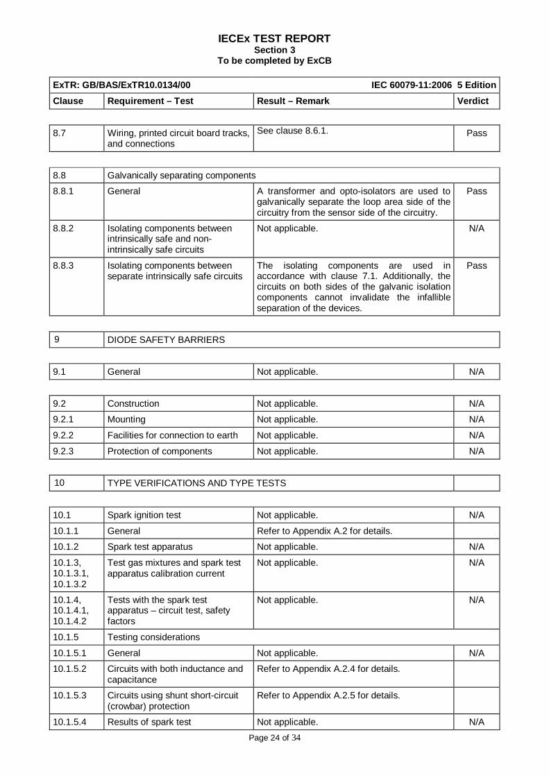
8.7 Wiring, printed circuit board tracks, and connections
See clause 8.6.1. Pass
8.8 Galvanically separating components
8.8.1 General A transformer and opto-isolators are used to galvanically separate the loop area side of the circuitry from the sensor side of the circuitry.
Pass
8.8.2 Isolating components between intrinsically safe and non-intrinsically safe circuits
Not applicable. N/A
8.8.3 Isolating components between separate intrinsically safe circuits
The isolating components are used in accordance with clause 7.1. Additionally, the circuits on both sides of the galvanic isolation components cannot invalidate the infallible separation of the devices.
Pass
9 DIODE SAFETY BARRIERS
9.1 General Not applicable. N/A
9.2 Construction Not applicable. N/A
9.2.1 Mounting Not applicable. N/A
9.2.2 Facilities for connection to earth Not applicable. N/A
9.2.3 Protection of components Not applicable. N/A
10 TYPE VERIFICATIONS AND TYPE TESTS
10.1 Spark ignition test Not applicable. N/A
10.1.1 General Refer to Appendix A.2 for details.
10.1.2 Spark test apparatus Not applicable. N/A
10.1.3, 10.1.3.1, 10.1.3.2
Test gas mixtures and spark test apparatus calibration current
Not applicable. N/A
10.1.4, 10.1.4.1, 10.1.4.2
Tests with the spark test apparatus – circuit test, safety factors
Not applicable. N/A
10.1.5 Testing considerations
10.1.5.1 General Not applicable. N/A
10.1.5.2 Circuits with both inductance and capacitance
Refer to Appendix A.2.4 for details.
10.1.5.3 Circuits using shunt short-circuit (crowbar) protection
Refer to Appendix A.2.5 for details.
10.1.5.4 Results of spark test Not applicable. N/A

IECEx TEST REPORT Section 3
To be completed by ExCB
Page 25 of 34
ExTR: GB/BAS/ExTR10.0134/00 IEC 60079-11:2006 5 Edition Clause Requirement – Test Result – Remark Verdict
10.2 Temperature tests Not applicable. N/A
10.3 Dielectric strength tests See clause 6.3.12. N/A
10.4 Determination of parameters of loosely specified components
Not applicable. N/A
10.5 Tests for cells and batteries
10.5.1 General Not applicable. N/A
10.5.2 Electrolyte leakage test for cells and batteries
Not applicable. N/A
10.5.3 Spark ignition and surface temperature of cells and batteries
Not applicable. N/A
10.5.4 Battery container pressure tests Not applicable. N/A
10.6 Mechanical tests
10.6.1 Casting compound Not applicable. N/A
10.6.2 Sealing of components before encapsulation
Not applicable. N/A
10.6.3 Partitions Not applicable. N/A
10.7 Tests for apparatus containing piezoelectric devices
Not applicable. N/A
10.8 Type tests for diode safety barriers and safety shunts
Not applicable. N/A
10.9 Cable pull test Not applicable. N/A
10.10 Transformer tests Not applicable. N/A
11 ROUTINE VERIFICATIONS AND TESTS
11.1 Routine tests for diode safety barriers
Not applicable. N/A
11.1.1 Completed barriers Not applicable. N/A
11.1.2 Diodes for 2-diode “ia” barriers Not applicable. N/A
11.2 Routine tests for infallible transformers
Not applicable. N/A
12 MARKING
IECEx TEST REPORT Section 3
To be completed by ExCB
Page 26 of 34
ExTR: GB/BAS/ExTR10.0134/00 IEC 60079-11:2006 5 Edition Clause Requirement – Test Result – Remark Verdict
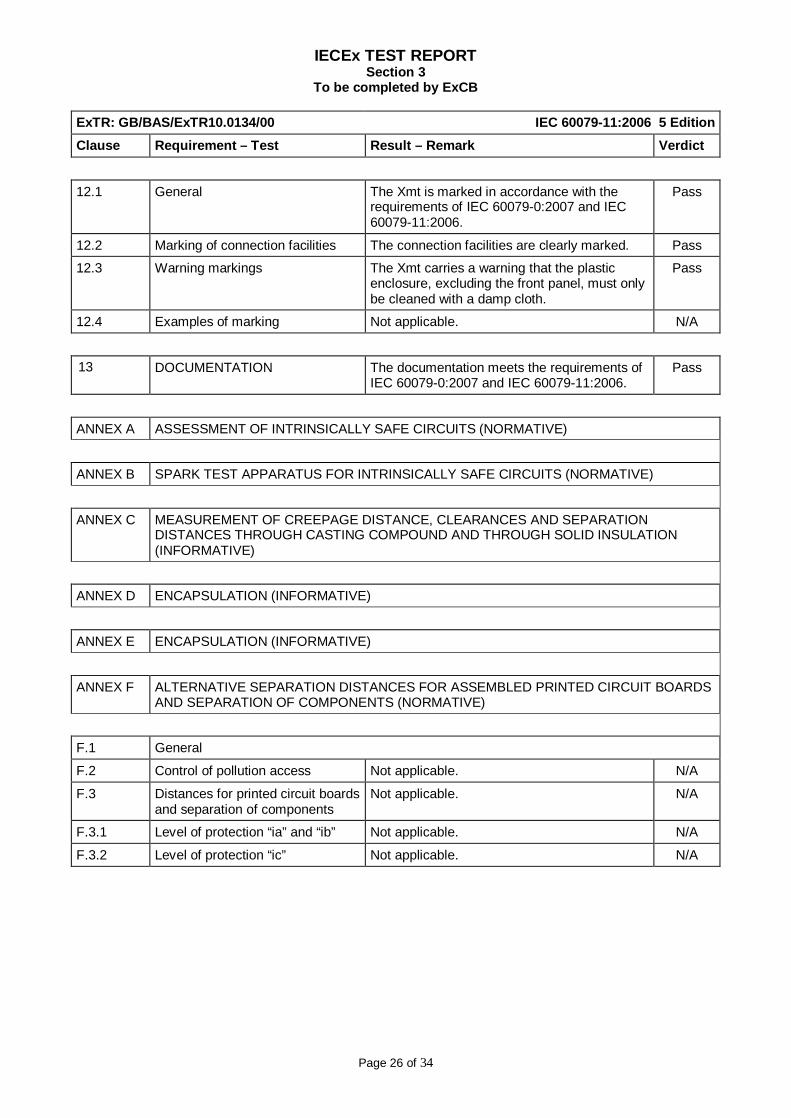
12.1 General The Xmt is marked in accordance with the requirements of IEC 60079-0:2007 and IEC 60079-11:2006.
Pass
12.2 Marking of connection facilities The connection facilities are clearly marked. Pass
12.3 Warning markings The Xmt carries a warning that the plastic enclosure, excluding the front panel, must only be cleaned with a damp cloth.
Pass
12.4 Examples of marking Not applicable. N/A
13 DOCUMENTATION The documentation meets the requirements of IEC 60079-0:2007 and IEC 60079-11:2006.
Pass
ANNEX A ASSESSMENT OF INTRINSICALLY SAFE CIRCUITS (NORMATIVE)
ANNEX B SPARK TEST APPARATUS FOR INTRINSICALLY SAFE CIRCUITS (NORMATIVE)
ANNEX C MEASUREMENT OF CREEPAGE DISTANCE, CLEARANCES AND SEPARATION DISTANCES THROUGH CASTING COMPOUND AND THROUGH SOLID INSULATION (INFORMATIVE)
ANNEX D ENCAPSULATION (INFORMATIVE)
ANNEX E ENCAPSULATION (INFORMATIVE)
ANNEX F ALTERNATIVE SEPARATION DISTANCES FOR ASSEMBLED PRINTED CIRCUIT BOARDS AND SEPARATION OF COMPONENTS (NORMATIVE)
F.1 General
F.2 Control of pollution access Not applicable. N/A
F.3 Distances for printed circuit boards and separation of components
Not applicable. N/A
F.3.1 Level of protection “ia” and “ib” Not applicable. N/A
F.3.2 Level of protection “ic” Not applicable. N/A
IECEx TEST REPORT Section 3
To be completed by ExCB
Page 27 of 34
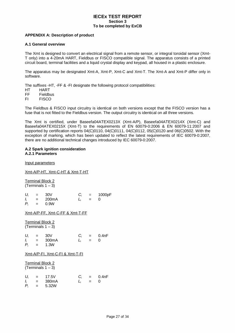
APPENDIX A: Description of product A.1 General overview The Xmt is designed to convert an electrical signal from a remote sensor, or integral toroidal sensor (Xmt-T only) into a 4-20mA HART, Fieldbus or FISCO compatible signal. The apparatus consists of a printed circuit board, terminal facilities and a liquid crystal display and keypad, all housed in a plastic enclosure. The apparatus may be designated Xmt-A, Xmt-P, Xmt-C and Xmt-T. The Xmt-A and Xmt-P differ only in software. The suffixes -HT, -FF & -FI designate the following protocol compatibilities: HT HART FF Fieldbus FI FISCO The Fieldbus & FISCO input circuitry is identical on both versions except that the FISCO version has a fuse that is not fitted to the Fieldbus version. The output circuitry is identical on all three versions. The Xmt is certified, under Baseefa04ATEX0213X (Xmt-A/P), Baseefa04ATEX0214X (Xmt-C) and Baseefa04ATEX0215X (Xmt-T) to the requirements of EN 60079-0:2006 & EN 60079-11:2007 and supported by certification reports 04(C)0110, 04(C)0111, 04(C)0112, 05(C)0120 and 06(C)0502. With the exception of marking, which has been updated to reflect the latest requirements of IEC 60079-0:2007, there are no additional technical changes introduced by IEC 60079-0:2007. A.2 Spark ignition consideration A.2.1 Parameters Input parameters Xmt-A/P-HT, Xmt-C-HT & Xmt-T-HT Terminal Block 2 (Terminals 1 – 3) Ui = 30V Ci = 1000pF Ii = 200mA Li = 0 Pi = 0.9W Xmt-A/P-FF, Xmt-C-FF & Xmt-T-FF Terminal Block 2 (Terminals 1 – 3) Ui = 30V Ci = 0.4nF Ii = 300mA Li = 0 Pi = 1.3W Xmt-A/P-FI, Xmt-C-FI & Xmt-T-FI Terminal Block 2 (Terminals 1 – 3) Ui = 17.5V Ci = 0.4nF Ii = 380mA Li = 0 Pi = 5.32W
IECEx TEST REPORT Section 3
To be completed by ExCB
Page 28 of 34
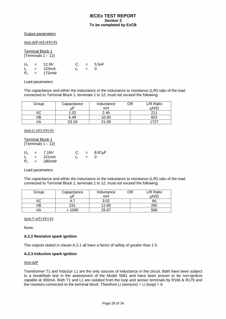
Output parameters Xmt-A/P-HT/-FF/-FI Terminal Block 1 (Terminals 1 – 12) Uo = 12.9V Ci = 5.5nF Io = 123mA Li = 0 Po = 172mW Load parameters The capacitance and either the inductance or the inductance to resistance (L/R) ratio of the load connected to Terminal Block 1, terminals 1 to 12, must not exceed the following:
Group Capacitance Inductance OR L/R Ratio µF mH µH/Ω
IIC 1.02 2.46 211 IIB 6.49 10.60 822 IIA 23.19 21.09 1727
Xmt-C-HT/-FF/-FI Terminal Block 1 (Terminals 1 – 12) Uo = 7.16V Ci = 8.81µF Io = 221mA Li = 0 Po = 280mW Load parameters The capacitance and either the inductance or the inductance to resistance (L/R) ratio of the load connected to Terminal Block 1, terminals 1 to 12, must not exceed the following:
Group Capacitance Inductance OR L/R Ratio µF mH µH/Ω
IIC 4.7 3.02 66 IIB 231 12.80 282 IIA > 1000 25.67 566
Xmt-T-HT/-FF/-FI None. A.2.2 Resistive spark ignition The outputs stated in clause A.2.1 all have a factor of safety of greater than 1.5. A.2.3 Inductive spark ignition Xmt-A/P Transformer T1 and Inductor L1 are the only sources of inductance in the circuit. Both have been subject to a breakflash test in the assessment of the Model 5081 and have been proven to be non-ignition capable at 300mA. Both T1 and L1 are isolated from the loop and sensor terminals by R166 & R179 and the resistors connected to the terminal block. Therefore Li (sensors) = Li (loop) = 0.

IECEx TEST REPORT Section 3
To be completed by ExCB
Page 29 of 34
Xmt-C Transformer T1 and Inductor L1 are the only sources of inductance in the circuit. Both have been subject to a breakflash test in the assessment of the Model 5081 and have been proven to be non-ignition capable at 300mA. Both T1 and L1 are isolated from the loop and sensor terminals by R166 & R179 and the resistors connected to the terminal block. Therefore Li (sensors) = Li (loop) = 0. Xmt-T Transformers T1, T2, the toroidal sensors and Inductor L1 are the only sources of inductance in the circuit. All have been subject to ignition testing as part of the assessment of the Model 5081T-HT/FF and proven to be non-ignition capable. The toroidal drive transformer, T2, is the same as that used in the Model 5081T and is subject to the same tests as T1 (and as detailed on drawing 9080140). T2 is a different designed to T1 and has the following inductance values (measured at 20ºC): Terminals 1 – 3: 280mH max. Terminals 4 – 5: 40µH max. Terminals 5 – 6: 6mH max. Both T1 and L1 are isolated from the loop terminals by R166 & R179 and T2 is isolated from the loop terminals by T1, therefore Li (loop) = 0. Rosemount Test Report LR1901-01 of 28 July 2004 details the breakflash testing conducted on the toroidal sensors to demonstrate a factor of safety of at least 1.5. No ignition was observed and therefore no further considerations are required. A.2.4 Capacitive spark ignition Xmt-A/P Resistors R166 and R179 effectively isolate all circuit capacitance on the primary side of the galvanic isolation from the loop/input terminals; transient suppressor D30 has a capacitance of 1000pF and is connected directly across the loop terminals. Therefore Ci = 1nF. The Ci for the sensor terminals is determined from the parallel combination of all the capacitors which are connected to the sensor terminals. Therefore Ci = 5.5nF. A breakflash test was completed on a capacitance model as detailed in Rosemount Test Report LR1796-01 and no ignition was observed. Xmt-C Resistors R166 and R179 effectively isolate all circuit capacitance on the primary side of the galvanic isolation from the loop/input terminals; transient suppressor D30 has a capacitance of 1000pF and is connected directly across the loop terminals. Therefore Ci = 1nF. The Ci for the sensor terminals is determined from the parallel combination of all the capacitors which are connected to the sensor terminals. Therefore Ci = 8.81µF. At a voltage of 7.16V, this capacitance has a factor of safety of greater than 1.6. A breakflash test was completed on a capacitance model as detailed in Rosemount Test Report LR1828-01 and no ignition was observed. Xmt-T Resistors R166 and R179 effectively isolate all circuit capacitance on the primary side of the galvanic isolation from the loop/input terminals; transient suppressor D30 has a capacitance of 1000pF and is connected directly across the loop terminals. Therefore Ci = 1nF.

IECEx TEST REPORT Section 3
To be completed by ExCB
Page 30 of 34
A breakflash test was completed on a capacitance model as detailed in Rosemount Test Report LR1828-01 and no ignition was observed. A.2.5 Combination of inductive and capacitive spark ignition See clause A.2.3. A.2.6 Shunt short-circuit (crowbar) spark ignition Not applicable. A.2.7 Other spark ignition considerations Not applicable. A.3 Thermal ignition consideration Xmt-A, Xmt-P, Xmt-C, Xmt-T HART (-HT) versions From Table 2b of IEC 60079-11:2006, it can be seen that given a maximum input power of 0.9W, a Temperature Classification of T4 in a -20ºC to +50ºC ambient can be awarded without further consideration for components with a surface area of not less than 20mm². The smallest ribbon cable has a cross sectional area of 0.048mm2, which permits approximately 5A for a Temperature Classification of T4 in a 40ºC ambient (from Table 3 of IEC 60079-11:2006). Therefore it is considered, that all ribbon cables are appropriate for a Temperature Classification of T4 in a 50ºC ambient as the maximum input current is limited to 200mA which is very much less than the 5A permitted, even introducing an additional 10ºC margin. The minimum track width on the board is 0.15mm which, from Table 4 of IEC 60079-11:2006, permits a maximum current of 1.2A for a Temperature Classification of T4 in a 40ºC; it is considered that, even with an additional 10ºC margin, the board wiring is appropriate for a current of 200mA in an ambient temperature of 50ºC. The SOT-23 packaged components have a thermal resistance of 220ºC/W so even when dissipating 0.9W in a 50ºC, the surface temperature will not exceed 248ºC. The Standard permits a maximum surface temperature for components less than 20mm2 of 275ºC, so adding a further 10ºC (to account for the difference in ambient temperatures) to the 248ºC obtained is still less than the permitted 275ºC. Xmt-A, Xmt-P, Xmt-C, Xmt-T Fieldbus/FISCO (-FF/-FI) versions Fieldbus (-FF) versions The supply is limited to 30V and the 199Ω combination of the two input resistors, the two resistors on the Fieldbus Communications Board and the barrier resistance (derived from R = V²/4P = 30²/(4×1.3) = 173Ω) limit the maximum input power to 1.13W (P=V2/4R where V=30V and R=199Ω). FISCO (-FI) versions The Fieldbus Communication Board, covered by BAS01ATEX1385U, is connected to connector block P1 and limits the maximum available power and voltage to 1.2W and 7.61V respectively. The input and output parameters of this board are as follows: Connector J1* pins 15 & 20 Ui = 17.5V Ci = 0 Ii = 380mA Li = 0 Pi = 1.5W
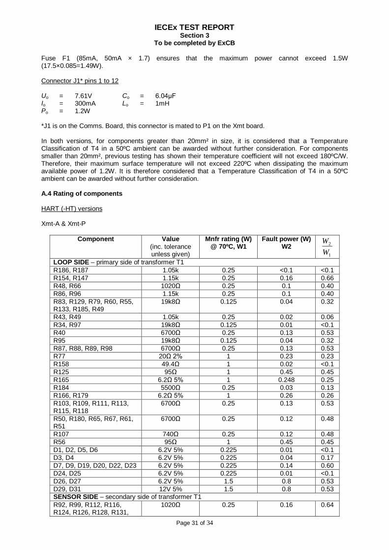
IECEx TEST REPORT Section 3
To be completed by ExCB
Page 31 of 34
Fuse F1 (85mA, 50mA × 1.7) ensures that the maximum power cannot exceed 1.5W (17.5×0.085=1.49W). Connector J1* pins 1 to 12 Uo = 7.61V Co = 6.04µF Io = 300mA Lo = 1mH Po = 1.2W *J1 is on the Comms. Board, this connector is mated to P1 on the Xmt board. In both versions, for components greater than 20mm² in size, it is considered that a Temperature Classification of T4 in a 50ºC ambient can be awarded without further consideration. For components smaller than 20mm², previous testing has shown their temperature coefficient will not exceed 180ºC/W. Therefore, their maximum surface temperature will not exceed 220ºC when dissipating the maximum available power of 1.2W. It is therefore considered that a Temperature Classification of T4 in a 50ºC ambient can be awarded without further consideration. A.4 Rating of components HART (-HT) versions Xmt-A & Xmt-P
Component Value (inc. tolerance unless given)
Mnfr rating (W) @ 70ºC, W1
Fault power (W) W2
1
2
WW
LOOP SIDE – primary side of transformer T1 R186, R187 1.05k 0.25 <0.1 <0.1 R154, R147 1.15k 0.25 0.16 0.66 R48, R66 1020Ω 0.25 0.1 0.40 R86, R96 1.15k 0.25 0.1 0.40 R83, R129, R79, R60, R55, R133, R185, R49
19k8Ω 0.125 0.04 0.32
R43, R49 1.05k 0.25 0.02 0.06 R34, R97 19k8Ω 0.125 0.01 <0.1 R40 6700Ω 0.25 0.13 0.53 R95 19k8Ω 0.125 0.04 0.32 R87, R88, R89, R98 6700Ω 0.25 0.13 0.53 R77 20Ω 2% 1 0.23 0.23 R158 49.4Ω 1 0.02 <0.1 R125 95Ω 1 0.45 0.45 R165 6.2Ω 5% 1 0.248 0.25 R184 5500Ω 0.25 0.03 0.13 R166, R179 6.2Ω 5% 1 0.26 0.26 R103, R109, R111, R113, R115, R118
6700Ω 0.25 0.13 0.53
R50, R180, R65, R67, R61, R51
6700Ω 0.25 0.12 0.48
R107 740Ω 0.25 0.12 0.48 R56 95Ω 1 0.45 0.45 D1, D2, D5, D6 6.2V 5% 0.225 0.01 <0.1 D3, D4 6.2V 5% 0.225 0.04 0.17 D7, D9, D19, D20, D22, D23 6.2V 5% 0.225 0.14 0.60 D24, D25 6.2V 5% 0.225 0.01 <0.1 D26, D27 6.2V 5% 1.5 0.8 0.53 D29, D31 12V 5% 1.5 0.8 0.53 SENSOR SIDE – secondary side of transformer T1 R92, R99, R112, R116, R124, R126, R128, R131,
1020Ω 0.25 0.16 0.64

IECEx TEST REPORT Section 3
To be completed by ExCB
Page 32 of 34
R137, R151, R156 R94, R145, R155, R192, R195, R197
1150Ω 0.25 0.15 0.60
R150, R153 19.8Ω 0.25 0.15 0.60 R85, R104, R105, R139, R152, R160
19800Ω 0.125 0.01 <0.1
R15, R16, R19, R27, R31, R32, R46, R47, R53, R54, R58, R64, R91, R130, R134, R159, R177, R178
6800Ω 0.25 0.02 <0.1
R188, R189 20Ω 1% 1 0.39 0.39 R191 200Ω 1% 1 0.16 0.16 D12 – D17 SMBJ5917
4.7V 5% 1.5 0.80 0.53
D32, D33 6.2V 5% 0.225 0.02 <0.1 Xmt-C
Component Value (inc. tolerance unless
given)
Mnfr rating (W) @ 70ºC, W1
Fault power (W) W2
1
2
WW
LOOP SIDE – primary side of transformer T1 R186, R187 1.05k 0.25 <0.1 <0.1 R154, R147 1.15k 0.25 0.16 0.66 R66 1020Ω 0.25 0.1 0.40 R48 19k8Ω 0.125 0.01 0.09 R86, R96 1.15k 0.25 0.1 0.40 R83, R129, R79, R60, R55, R133, R185
19k8Ω 0.125 0.04 0.32
R43 6700Ω 0.25 0.033 0.13 R49 1.05k 0.25 0.016 0.06 R34, R97 19k8Ω 0.125 0.01 <0.1 R40 6700Ω 0.25 0.13 0.53 R95 19k8Ω 0.125 0.04 0.32 R87, R88, R89, R98 6700Ω 0.25 0.13 0.53 R77 20Ω 2% 1 0.23 0.23 R158 49.4Ω 1 0.02 <0.1 R125 95Ω 1 0.45 0.45 R165 6.2Ω 5% 1 0.248 0.25 R184 5500Ω 0.25 0.03 0.13 R166, R179 6.2Ω 5% 1 0.26 0.26 R103, R109, R111, R113, R115, R118
6700Ω 0.25 0.13 0.53
R50, R180, R65, R67, R61, R51
6700Ω 0.25 0.12 0.48
R107 740Ω 0.25 0.12 0.48 R56 95Ω 1 0.45 0.45 D1, D2, D5, D6 6.2V 5% 0.225 0.01 <0.1 D3, D4 6.2V 5% 0.225 0.04 0.17 D7, D9, D19, D20, D22, D23
6.2V 5% 0.225 0.14 0.60
D24, D25 6.2V 5% 0.225 0.01 <0.1 D26, D27 6.2V 5% 1.5 0.8 0.53 D29, D31 12V 5% 1.5 0.8 0.53 SENSOR SIDE – secondary side of transformer T1 R134, R139, R152,R159
6700Ω 0.25 0.01 <0.1
R71 19k8Ω 0.125 0.01 <0.1 D12, D18 SMBJ5917 1.5 0.8 0.53

IECEx TEST REPORT Section 3
To be completed by ExCB
Page 33 of 34
R130 20Ω 1% 1 R90 >680Ω 0.25 0.06 0.24 D16, D32 If ≥ 200mA
Vrb ≥10V If ≤ 0.98mA Vrb ≤ 6.59V
≤0.10 ≤0.66
R53 6700Ω 0.25 0.01 <0.1 D13, D15 SMBJ5920 1.5 0.8 0.53 R112, R114 20Ω 1% 1 0.52 0.52 R123, R124, R131,R132
6700Ω 0.25 0.01 <0.1
R108 >246Ω 0.25 0.15 0.60 R93 >494Ω 0.25 0.08 0.32 R153, R156 1.15kΩ 0.25 0.04 0.16 R99 19k8Ω 0.125 0.01 <0.1 R145, R155 1.15kΩ 0.25 0.03 0.14 R74 6700Ω 0.25 0.01 <0.1
Xmt-T
Component Value (inc. tolerance unless given)
Mnfr rating (W) @ 70ºC, W1
Fault power (W) W2
1
2
WW
LOOP SIDE – primary side of transformer T1 R186, R187 1.05k 0.25 <0.1 <0.1 R154, R147 1.15k 0.25 0.16 0.66 R48, R66 1020Ω 0.25 0.1 0.40 R86, R96 1.15k 0.25 0.1 0.40 R83, R129, R79, R60, R55, R133, R185, R40, R43, R49
19k8Ω 0.125 0.04 0.32
R34, R97, R87, R88, R89, R98, R95
19k8Ω 0.125 0.01 <0.1
R77 20Ω 2% 1 0.23 0.23 R158 49.4Ω 1 0.02 <0.1 R125 95Ω 1 0.45 0.45 R165 6.2Ω 5% 1 0.248 0.25 R184 5500Ω 0.25 0.03 0.13 R166, R179 6.2Ω 5% 1 0.26 0.26 R103, R109, R111, R113, R115, R118
6700Ω 0.25 0.13 0.53
R50, R180, R65, R67, R61, R51
6700Ω 0.25 0.12 0.48
R107 740Ω 0.25 0.12 0.48 R56 95Ω 1 0.45 0.45 D1, D2, D5, D6 6.2V 5% 0.225 0.01 <0.1 D3, D4 6.2V 5% 0.225 0.04 0.17 D7, D9, D19, D20, D22, D23 6.2V 5% 0.225 0.14 0.60 D24, D25 6.2V 5% 0.225 0.01 <0.1 D26, D27 6.2V 5% 1.5 0.8 0.53 D29, D31 12V 5% 1.5 0.8 0.53 SENSOR SIDE – secondary side of transformer T1 R124 100Ω 1% 1 0.12 0.12 R156, R157 1150Ω 0.25 0.09 0.36 R72, R74 1150Ω 0.25 0.15 0.60 R8, R12 198Ω 0.25 0.09 0.34 R139 198Ω 1 0.09 <0.1 R126, R134, R140, R71, R120
19k8Ω 0.125 0.01 <0.1
R131 200Ω 1% 1 0.54 0.54 R112 49.9Ω 1% 1 0.21 0.21 R14, R121, R114, R82 6700Ω 0.25 0.02 <0.1
IECEx TEST REPORT Section 3
To be completed by ExCB
Page 34 of 34
Component Value (inc. tolerance unless given)
Mnfr rating (W) @ 70ºC, W1
Fault power (W) W2
1
2
WW
R5, R7 990Ω 0.25 0.11 0.44 R13 99Ω 0.25 0.07 0.27 D18, D35 0.225 <0.1 <0.1 D12 - D17, D33, D34 1.5 0.8 0.53 D36-D38 4.7V±5% 0.225 0.09 0.41
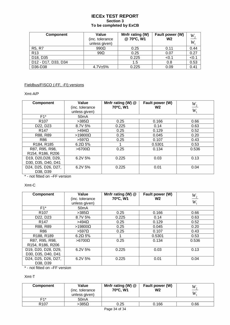
Fieldbus/FISCO (-FF, -FI) versions Xmt-A/P
Component Value (inc. tolerance unless given)
Mnfr rating (W) @ 70ºC, W1
Fault power (W) W2
1
2
WW
F1* 50mA R107 >385Ω 0.25 0.166 0.66
D22, D23 8.7V 5% 0.225 0.14 0.63 R147 >494Ω 0.25 0.129 0.52
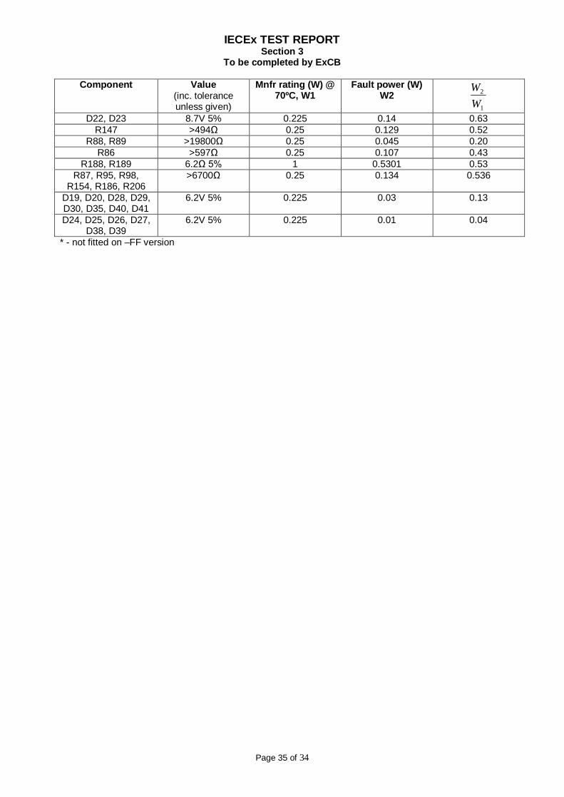
R88, R89 >19800Ω 0.25 0.045 0.20 R86 >597Ω 0.25 0.107 0.43
R184, R185 6.2Ω 5% 1 0.5301 0.53 R87, R95, R98,
R154, R186, R206 >6700Ω 0.25 0.134 0.536
D19, D20,D28, D29, D30, D35, D40, D41
6.2V 5% 0.225 0.03 0.13
D24, D25, D26, D27, D38, D39
6.2V 5% 0.225 0.01 0.04
* - not fitted on –FF version Xmt-C
Component Value (inc. tolerance unless given)
Mnfr rating (W) @ 70ºC, W1
Fault power (W) W2
1
2
WW
F1* 50mA R107 >385Ω 0.25 0.166 0.66
D22, D23 8.7V 5% 0.225 0.14 0.63 R147 >494Ω 0.25 0.129 0.52
R88, R89 >19800Ω 0.25 0.045 0.20 R86 >597Ω 0.25 0.107 0.43
R188, R189 6.2Ω 5% 1 0.5301 0.53 R87, R95, R98,
R154, R186, R206 >6700Ω 0.25 0.134 0.536
D19, D20, D28, D29, D30, D35, D40, D41
6.2V 5% 0.225 0.03 0.13
D24, D25, D26, D27, D38, D39
6.2V 5% 0.225 0.01 0.04
* - not fitted on –FF version Xmt-T
Component Value (inc. tolerance unless given)
Mnfr rating (W) @ 70ºC, W1
Fault power (W) W2
1
2
WW
F1* 50mA R107 >385Ω 0.25 0.166 0.66
IECEx TEST REPORT Section 3
To be completed by ExCB
Page 35 of 34
Component Value (inc. tolerance unless given)
Mnfr rating (W) @ 70ºC, W1
Fault power (W) W2
1
2
WW
D22, D23 8.7V 5% 0.225 0.14 0.63 R147 >494Ω 0.25 0.129 0.52
R88, R89 >19800Ω 0.25 0.045 0.20 R86 >597Ω 0.25 0.107 0.43
R188, R189 6.2Ω 5% 1 0.5301 0.53 R87, R95, R98,
R154, R186, R206 >6700Ω 0.25 0.134 0.536
D19, D20, D28, D29, D30, D35, D40, D41
6.2V 5% 0.225 0.03 0.13
D24, D25, D26, D27, D38, D39
6.2V 5% 0.225 0.01 0.04
* - not fitted on –FF version