ieee 1588v2 ptp support - cisco · ieee 1588v2 ptp support...
TRANSCRIPT

IEEE 1588v2 PTP Support
IEEE 1588v2 Precision Time Protocol (PTP) is a packet-based two-way message exchange protocol forsynchronizing clocks between nodes in a network, thereby enabling an accurate time distribution over anetwork.This document explains how to configure IEEE 1588v2 PTP on the Cisco ASR 1002-X Routers.
• Restrictions for IEEE 1588v2 PTP, page 1
• Information About IEEE 1588v2 PTP , page 1
• Configuring IEEE 1588v2 PTP, page 10
• Additional References, page 22
• Feature Information for IEEE 1588v2 PTP Support, page 22
Restrictions for IEEE 1588v2 PTPThese are the restrictions for configuring IEEE 1588v2 PTP:
• Supports IPv4 unicast mode, but not multicast mode.
• Does not support Dot1q, Q-in-Q, and port-channel interfaces.
• PTP master supports only a maximum of 32 PTP slaves.
• PTP boundary clock is supported only in unicast negotiation mode.
• IPv6 andMultiprotocol Label Switching (MPLS) encapsulation are not supported for PTP packet transferover Cisco ASR 1002-X Routers.
• The time-of-day recovered from a 1588v2 session does not synchronize with the system clock.
• GPS interfaces can be used only for clock recovery. You cannot transmit the system clock on the GPSinterface.
Information About IEEE 1588v2 PTPIEEE 1588v2 PTP is a packet-based two-way message exchange protocol for synchronizing a local clockwith a primary reference clock or a grand master clock in hierarchical master-slave architecture. This
Cisco ASR 1000 Series Aggregation Services Routers Software Configuration Guide 1

synchronization is achieved through packets that are transmitted and received in a session between a masterclock and a slave clock. IEEE 1588v2 PTP supports system-wide synchronization accuracy in thesub-microsecond range with little use of network and local clock-computing resources.
The following sections describe the terminologies used for better understanding of the IEEE 1588v2 PTP.
PTP ClocksPTP employs a hierarchy of clock types to ensure that precise timing and synchronization is maintainedbetween the source and the numerous PTP clients that are distributed throughout the network. A logicalgrouping of PTP clocks that synchronize with each other using the PTP protocol, but are not necessarilysynchronized to the PTP clocks in another domain, is called a PTP domain.
The three PTP clock types are Ordinary clock, Boundary clock, and Transparent clock.
• Ordinary clock—This clock type has a single PTP port in a domain, and maintains the timescale usedin the domain. It may serve as a source of time, that is, be a master, or may synchronize to another clockby being a slave. It provides time to an application or to an end device.
• Boundary clock—This clock type has multiple PTP ports in a domain, and maintains the timescaleused in the domain. It may serve as a source of time, that is, be a master, or may synchronize to anotherclock by being a slave. A boundary clock that is a slave has a single slave port, and transfers timing fromthat port to the master ports.
• Transparent clock—This clock type is a device that measures the time taken for a PTP event messageto pass through the device, and provides this information to the clocks receiving this PTP event message.
{start cross reference}Table 13-1{end cross reference} shows the 1588v2 PTP support matrix on a CiscoASR1000 platform.
Table 1: 1588v2 PTP Support Matrix on a Cisco ASR1000 platform
Hybrid ClockTransparent ClockBoundary ClockOrdinary ClockPlatform/PTP Clockmode
NoNoYesYesASR1002X
Components of a PTP-enabled NetworkThe three key components of a PTP-enabled data network are grand master, PTP client, and PTP-enabledrouter acting as a Boundary clock.
• Grand Master—An IEEE1588v2 PTP network needs a grand master to provide a precise time source.The most economical way of obtaining the precise time source for the grand master is through a GlobalPositioning System (GPS) because it provides +/- 100 nanosecond (ns) accuracy. First, the PTP grandmaster’s built-in GPS receiver converts the GPS timing information to PTP time information, which istypically Coordinated Universal Time (UTC), and then delivers the UTC time to all the PTP clients.
• PTP client—A PTP client has to be installed on servers, network-monitoring and performance-analysisdevices, or other devices that want to use the precise timing information provided by PTP, and it’s mostly
Cisco ASR 1000 Series Aggregation Services Routers Software Configuration Guide2
IEEE 1588v2 PTP SupportPTP Clocks

an ordinary clock. The two kinds of PTP clients are pure software PTP clients and hardware-assistantPTP clients.
• PTP boundary clock—Any router that is between a PTPmaster and PTP slave can act as a PTP boundaryclock router. It has two interfaces, one facing the PTP master and another facing the PTP slave. Theboundary clock router acts as a slave on the interface facing the PTP master router , and acts as amasteron the interface facing the PTP slave router . The PTP boundary clock router is deployed to minimizetiming delay in cases where the distance between PTP master router and the PTP slave router is more.
Intermediary nodes between PTP master and slave should be a PTP-enabled or transparent clock node.Note
The following figure shows the functions of a PTP Enabled device.
Figure 1: 372860.eps Functions of a PTP-Enabled Device
Cisco ASR 1000 Series Aggregation Services Routers Software Configuration Guide 3
IEEE 1588v2 PTP SupportComponents of a PTP-enabled Network

Clock-Synchronization ProcessClock synchronization is achieved through a series of messages exchanged between the master clock and theslave clock as shown in the figure.
Figure 2: Clock-Synchronization Process
After the master-slave clock hierarchy is established, the clock synchronization process starts. The messageexchange occurs in this sequence:
1 The master clock sends a Sync message. The time at which the Sync message leaves the master istime-stamped as t{start subscript}1{end subscript}.
2 The slave clock receives the Sync message and is time-stamped as t{start subscript}2{end subscript}.3 The slave sends the Delay_Req message, which is time-stamped as t{start subscript}3{end subscript}
when it leaves the slave, and as t{start subscript}4{end subscript} when the master receives it.4 The master responds with a Delay_Resp message that contains the time stamp t{start subscript}4{end
subscript}.
The clock offset is the difference between the master clock and the slave clock, and is calculated as follows:
Offset = t{start subscript}2{end subscript} - t{start subscript}1{end subscript} - meanPathDelay
IEEE1588 assumes that the path delay between the master clock and the slave clock is symmetrical, and hence,the mean path delay is calculated as follows:
meanPathDelay = ((t{start subscript}2{end subscript} - t{start subscript}1{end subscript}) + (t{startsubscript}4{end subscript} - t{start subscript}3{end subscript}))/2
Cisco ASR 1000 Series Aggregation Services Routers Software Configuration Guide4
IEEE 1588v2 PTP SupportClock-Synchronization Process

PTP MessagesAll PTP communication is performed through message exchange. The two sets of messages defined byIEEE1588v2 are General messages and Event messages.
• Generalmessages—Thesemessages do not require accurate time stamps, and are classified as Announce,Follow_Up, Delay_Resp, Pdelay_Resp_Follow_Up, Management, and Signaling.
• Eventmessages—Thesemessages require accurate time stamping, and are classified as Sync, Delay_Req,Pdelay_Req, and Pdelay_Resp.
PTP Clocking ModesThe following are the PTP clocking modes supported on a Cisco ASR 1002-X Router:
• Unicast Mode—In unicast mode, the master sends the Sync or Delay_Resp messages to the slave onthe unicast IP address of the slave, and the slave in turn sends the Delay_Req message to the master onthe unicast IP address of the master.
• Unicast Negotiation Mode—In unicast negotiation mode, the master does not know of any slave untilthe slave sends a negotiation message to the master. The unicast negotiation mode is good for scalabilitypurpose because one master can have multiple slaves.
PTP AccuracyAccuracy is an important aspect of PTP implementation on an Ethernet port. For a packet network, PacketDelay Variation (PDV) is one of the key factors that impacts the accuracy of a PTP clock. The Cisco ASR1002-X Router can handle the PDV of the network with its advanced hardware and software capabilities, suchas hardware stamping and special high-priority queue for PTP packets. It can provide around 300 ns accuracyin a scalable deployment scenario.
The two methods used on the same topology to cross-check and verify the results are:
• One-pulse-per-second (1PPS) to verify the PTP slave.
• Maximum Time Interval Error (MTIE) and Time Deviation (TDEV) to verify the PDV.
Cisco ASR 1000 Series Aggregation Services Routers Software Configuration Guide 5
IEEE 1588v2 PTP SupportPTP Messages

The verification topology includes a grand master with a GPS receiver, a Cisco ASR 1002-X Router, PTPhardware slave clocks with 1PPS output, and a test equipment for the measurement.
Figure 3: 1PPS Accuracy Measurement
Cisco ASR 1000 Series Aggregation Services Routers Software Configuration Guide6
IEEE 1588v2 PTP SupportPTP Accuracy

The following figure shows the PPS accuracy, with time of day measured using the test equipment as per thetopology shown in the following figure. The average PPS accuracy value found is 250 ns.
Figure 4: Graph Showing PPS Accuracy
Cisco ASR 1000 Series Aggregation Services Routers Software Configuration Guide 7
IEEE 1588v2 PTP SupportPTP Accuracy
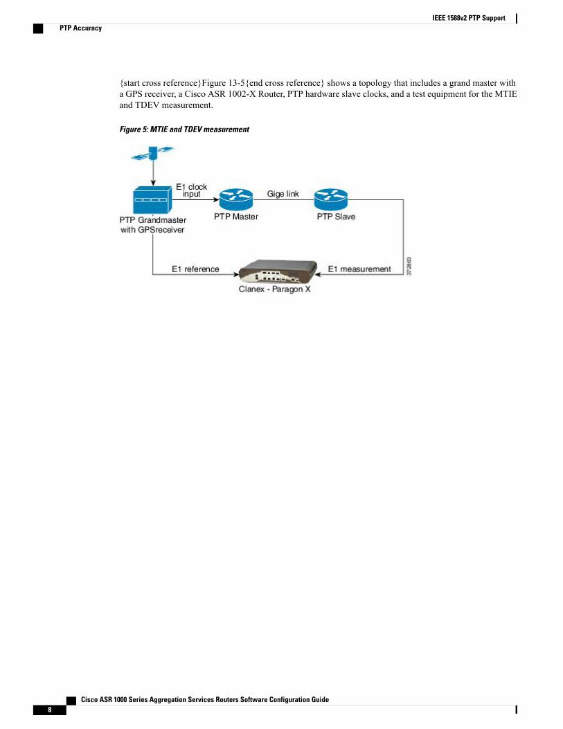
{start cross reference}Figure 13-5{end cross reference} shows a topology that includes a grand master witha GPS receiver, a Cisco ASR 1002-X Router, PTP hardware slave clocks, and a test equipment for the MTIEand TDEV measurement.
Figure 5: MTIE and TDEV measurement
Cisco ASR 1000 Series Aggregation Services Routers Software Configuration Guide8
IEEE 1588v2 PTP SupportPTP Accuracy

{start cross reference}Figure 13-6{end cross reference} shows a graphwith theMTIE and TDEVmeasurementsto verify the PDV.
Figure 6: Graph to show MTIE and TDEV Measurement
IEEE 1588v2 PTP SupportIEEE 1588v2 PTP supports these features on a Cisco ASR1002-X Router:
• Two-step Ordinary clock and Boundary clock.
• Hardware-assistant PTP implementation to provide sub-300 ns accuracy.
• PTP operation on all physical onboard Gigabit Ethernet interfaces.
Cisco ASR 1000 Series Aggregation Services Routers Software Configuration Guide 9
IEEE 1588v2 PTP SupportIEEE 1588v2 PTP Support

• Supports built-in Gigabit Ethernet links in two-step clock mode.
Configuring IEEE 1588v2 PTPYou can configure IEEE 1588v2 PTP features on the Cisco ASR 1002-X Router by performing the followingprocedures:
Configuring Input or Output Network ClockingWe recommend that you configure a stable input clock source from a GPS device before configuring PTPmaster. The GPS device acts as a PTP grand master, and the BITS or 10-MHz port of a Cisco ASR 1002-XRouter can be used to input or output the network clock. Perform these tasks to configure network clockingon a Cisco ASR 1002-X Router:
Configuring an Ordinary ClockYou can configure a Cisco ASR 1002-X Router in Ordinary clock mode as either master or slave.
Figure 7: Ordinary Clock Scenario with a GPS Device as Grand Master
Perform these tasks to configure an ordinary clock as either master or slave:
Configuring an Ordinary Clock as PTP MasterThis section describes how to configure an ordinary clock as PTP master.
SUMMARY STEPS
1. configure terminal2. ptp clock ordinary domain domain_number3. clock-port namemaster4. transport ipv4 unicast interface {GigabitEthernet | Loopback} interface-number [negotiation]5. clock destination ip-address6. sync interval interval7. end
Cisco ASR 1000 Series Aggregation Services Routers Software Configuration Guide10
IEEE 1588v2 PTP SupportConfiguring IEEE 1588v2 PTP

DETAILED STEPS
PurposeCommand or Action
Enters global configuration mode.configure terminal
Example:
Router# configure terminal
Step 1
Creates a PTP clock and specifies the clock mode.ptp clock ordinary domain domain_number
Example:
Router(config)# ptp clock ordinary domain 0
Step 2
Specifies the clocking mode of a PTP port and enters the clockport configuration mode.
clock-port namemaster
Example:
Router(config-ptp-clk)# clock-port MASTERmaster
Step 3
Specifies the IP version, transmission mode, and interface thata PTP clock port uses to exchange timing packets.
transport ipv4 unicast interface {GigabitEthernet| Loopback} interface-number [negotiation]
Step 4
Example:
Router(config-ptp-port)# transport ipv4 unicastinterface Loopback11 negotiation
The negotiation keyword specifies the unicast negotiationmodewhere the slave andmaster clock exchange negotiationmessagesbefore establishing a relationship.
Only Loopback interface type issupported.
Note
Specifies the IP address of a PTP clock destination.clock destination ip-addressStep 5
Example:
Router(config-ptp-port)# clock destination20.20.20.20
If the clock port is set to master mode with unicast negotiation,you need not use this command because the device usesnegotiation to determine the IP address of PTP slave devices.
(Optional) Specifies the interval used to send PTPsynchronization messages.
sync interval interval
Example:
Router(config-ptp-port)# sync interval -4
Step 6
The default value is -5.
Exits global configuration mode.end
Example:
Step 7
Example:
Router(config-ptp-port)# end
Cisco ASR 1000 Series Aggregation Services Routers Software Configuration Guide 11
IEEE 1588v2 PTP SupportConfiguring an Ordinary Clock

Examples
The following example shows how to configure an ordinary clock as PTP master:
Router# configure terminalRouter(config)# ptp clock ordinary domain 0Router(config-ptp-clk)# clock-port MASTER masterRouter(config-ptp-port)# transport ipv4 unicast interfaceLoopback11negotiationRouter(config-ptp-port)# clock destination20.20.20.20Router(config-ptp-port)# Sync interval
-4Router(config-ptp-port)# end
Configuring an Ordinary Clock as PTP SlaveThis section describes how to configure Ordinary Clock as PTP slave.
SUMMARY STEPS
1. configure terminal2. ptp clock ordinary domain domain_number3. clock-port name slave4. transport ipv4 unicast interface {GigabitEthernet | Loopback} interface-number [negotiation]5. clock source ip-address6. end
DETAILED STEPS
PurposeCommand or Action
Enters global configuration mode.configure terminal
Example:
Router# configure terminal
Step 1
Creates a PTP clock and specifies the clock mode.ptp clock ordinary domain domain_number
Example:
Router(config)# ptp clock ordinary domain 0
Step 2
Specifies the clocking mode of a PTP port and enters the clockport configuration mode.
clock-port name slave
Example:
Router(config-ptp-clk)# clock-port SLAVE slave
Step 3
Cisco ASR 1000 Series Aggregation Services Routers Software Configuration Guide12
IEEE 1588v2 PTP SupportConfiguring an Ordinary Clock

PurposeCommand or Action
Specifies the IP version, transmission mode, and interface thata PTP clock port uses to exchange timing packets.
transport ipv4 unicast interface {GigabitEthernet| Loopback} interface-number [negotiation]
Step 4
Example:
Router(config-ptp-port)# transport ipv4 unicastinterface Loopback22 negotiation
The negotiation keyword specifies the unicast negotiationmode where the slave and master clock exchanges negotiationmessages before establishing a relationship.
Only Loopback interface type issupported.
Note
Specifies the source IP address of a PTP master clock.clock source ip-addressStep 5
Example:
Router(config-ptp-port)# clock source10.10.10.10
You can specify only 1 master clock IP address.Priority-based clock source selection is not supported.
Note
Exits global configuration mode.end
Example:
Router(config-ptp-port)# end
Step 6
Examples
The following example shows how to configure an ordinary clock as PTP slave:
Router# configure terminalRouter(config)# ptp clock ordinary domain 0Router(config-ptp-clk)# clock-port SLAVE masterRouter(config-ptp-port)# transport ipv4 unicast interfaceLoopback22negotiationRouter(config-ptp-port)# clock source10.10.10.10Router(config-ptp-port)# end
Configuring a Boundary ClockYou can configure the PTP master and PTP slave in a boundary clock topology as shown in the figure in thesameway that you configure amaster and slave in ordinary clockmode. This section describes how to configurea Cisco ASR 1002-X Router in boundary clock mode.
Cisco ASR 1000 Series Aggregation Services Routers Software Configuration Guide 13
IEEE 1588v2 PTP SupportConfiguring a Boundary Clock

Currently, boundary clock supports only unicast negotiation mode.Note
Figure 8: PTP Boundary Clock Scenario
SUMMARY STEPS
1. configure terminal2. ptp clock boundary domain domain_number3. clock-port name slave4. transport ipv4 unicast interface {GigabitEthernet | Loopback} interface-number [negotiation]5. clock source ip-address6. exit7. clock-port name master8. transport ipv4 unicast interface {GigabitEthernet | Loopback} interface-number [negotiation]9. end
DETAILED STEPS
PurposeCommand or Action
Enters the global configuration mode.configure terminal
Example:
Router# configure terminal
Step 1
Creates a PTP clock and specifies the clock mode.ptp clock boundary domain domain_number
Example:
Router(config)# ptp clock boundary domain 0
Step 2
Specifies the clocking mode of a PTP port and enters the clockport configuration mode.
clock-port name slave
Example:
Router(config-ptp-clk)# clock-port SLAVE slave
Step 3
Specifies the IP version, transmission mode, and interface thata PTP clock port uses to exchange timing packets.
transport ipv4 unicast interface {GigabitEthernet| Loopback} interface-number [negotiation]
Step 4
Cisco ASR 1000 Series Aggregation Services Routers Software Configuration Guide14
IEEE 1588v2 PTP SupportConfiguring a Boundary Clock

PurposeCommand or Action
Example:
Router(config-ptp-port)# transport ipv4 unicastinterface Loopback11 negotiation
The negotiation keyword specifies the unicast negotiationmodewhere the slave andmaster clock exchange negotiationmessagesbefore establishing a relationship.
Only Loopback interface type issupported.
Note
Specifies the source IP address of a PTP master clock.clock source ip-addressStep 5
Example:
Router(config-ptp-port)# clock source10.10.10.10
You can specify only one master clock IP address.Priority-based clock source selection is not supported.
Note
Exits clock port configuration mode.exit
Example:
Router(config-ptp-port)# exit
Step 6
Specifies the clocking mode of a PTP port and enters clock portconfiguration mode.
clock-port name master
Example:
Router(config-ptp-clk)# clock-port MASTERmaster
Step 7
Specifies the IP version, transmission mode, and interface thata PTP clock port uses to exchange timing packets.
transport ipv4 unicast interface {GigabitEthernet| Loopback} interface-number [negotiation]
Step 8
Example:
Router(config-ptp-port)# transport ipv4 unicastinterface Loopback10 negotiation
The negotiation keyword specifies the unicast negotiationmodewhere the slave andmaster clock exchange negotiationmessagesbefore establishing a relationship.
Only Loopback interface type issupported.
Note
Exits global configuration mode.end
Example:
Step 9
Example:
Router(config-ptp-port)# end
ExamplesThe following example shows how to configure a boundary clock:
Router# configure terminalRouter(config)# ptp clock ordinary domain 0Router(config-ptp-clk)# clock-port SLAVE slaveRouter(config-ptp-port)# transport ipv4 unicast interface
Cisco ASR 1000 Series Aggregation Services Routers Software Configuration Guide 15
IEEE 1588v2 PTP SupportConfiguring a Boundary Clock

Loopback11negotiationRouter(config-ptp-port)# clock source10.10.10.10Router(config-ptp-port)# exitRouter(config-ptp-clk)# clock-port MASTER masterRouter(config-ptp-port)# transport ipv4 unicast interfaceLoopback10negotiationRouter(config-ptp-port)# end
Configuring Time of DayA Cisco ASR 1002-X Router can exchange time of day and 1PPS input with an external device, such as aGPS receiver, using the time of day and 1PPS input and output interfaces on the router.
Perform these tasks to configure Time of Day (ToD) messages on the Cisco ASR 1002-X Router:
Configuring Input Time-of-Day MessagesThis section describes how to configure input time-of-day messages.
You can configure time-of-day input only in a PTP master clock port.Note
SUMMARY STEPS
1. configure terminal2. ptp clock ordinary domain domain_number3. tod {R0 | R1} {cisco | ntp}4. input [1pps] { R0 | R1 }5. clock-port name master6. transport ipv4 unicast interface {GigabitEthernet | Loopback} interface-number [negotiation]7. clock destination ip-address8. end
DETAILED STEPS
PurposeCommand or Action
Enters global configuration mode.configure terminal
Example:
Router# configure terminal
Step 1
Cisco ASR 1000 Series Aggregation Services Routers Software Configuration Guide16
IEEE 1588v2 PTP SupportConfiguring Time of Day

PurposeCommand or Action
Creates a PTP clock and specifies the clock mode.ptp clock ordinary domain domain_number
Example:
Router(config)# ptp clock ordinary domain0
Step 2
Configures the time-of-day message format used by the 1PPS orBITS interface.
tod {R0 | R1} {cisco | ntp}
Example:
Step 3
Currently, only R0 1PPS port is supported; R1 is not valid.Also, only ntp mode is supported, not cisco mode.
Note
Example:
Router(config-ptp-clk)# tod R0 ntp
Enables PTP input clocking using a 1.544-Mhz, 2.048-Mhz, or10-Mhz timing interface, or phase using the 1PPS or RS-422interface.
input [1pps] { R0 | R1 }
Example:
Router(config-ptp-clk)# input 1pps R0
Step 4
Currently, only R0 1PPS port is supported; R1 is not valid.Note
Specifies the clockingmode of a PTP port and enters the clock portconfiguration mode.
clock-port name master
Example:
Router(config-ptp-clk)# clock-port MASTERmaster
Step 5
Specifies the IP version, transmission mode, and interface that aPTP clock port uses to exchange timing packets.
transport ipv4 unicast interface{GigabitEthernet | Loopback} interface-number[negotiation]
Step 6
The negotiation keyword specifies the unicast negotiation modewhere the slave and master clock exchange negotiation messagesbefore establishing a relationship.Example:
Router(config-ptp-port)# transport ipv4unicast interface Loopback11 negotiation
Only Loopback interface type issupported.
Note
Specifies the IP address of a PTP clock destination.clock destination ip-addressStep 7
Example:
Router(config-ptp-port)# clock destination20.20.20.20
If the clock port is set to master mode with unicast negotiation, youneed not use this command because the device uses negotiation todetermine the IP address of PTP slave devices.
Exits global configuration mode.end
Example:
Router(config-ptp-port)# end
Step 8
Cisco ASR 1000 Series Aggregation Services Routers Software Configuration Guide 17
IEEE 1588v2 PTP SupportConfiguring Time of Day

What to Do Next
Examples
The following example shows how to configure input time-of-day messages:
Router# configure terminalRouter(config)# ptp clock ordinary domain 0Router(config-ptp-clk)# tod R0 ntpRouter(config-ptp-clk)# input1pps R0Router(config-ptp-clk)# clock-port MASTER masterRouter(config-ptp-port)# transport ipv4 unicast interfaceLoopback11negotiationRouter(config-ptp-port)# clock destination20.20.20.20
Router(config-ptp-port)# end
Configuring Output Time-of-Day MessagesThis section describes how to configure output time-of-day messages.
You can configure ToD output only on PTP slave clock ports.Note
SUMMARY STEPS
1. configure terminal2. ptp clock ordinary domain domain_number3. tod {R0 | R1} {cisco | ntp}4. output [1pps] { R0 | R1 }5. clock-port name slave6. transport ipv4 unicast interface {GigabitEthernet | Loopback} interface-number [negotiation]7. clock source ip-address8. end
DETAILED STEPS
PurposeCommand or Action
Enters global configuration mode.configure terminal
Example:
Router# configure terminal
Step 1
Cisco ASR 1000 Series Aggregation Services Routers Software Configuration Guide18
IEEE 1588v2 PTP SupportConfiguring Time of Day

PurposeCommand or Action
Creates a PTP clock and specifies the clock mode.ptp clock ordinary domain domain_number
Example:
Router(config)# ptp clock ordinary domain 0
Step 2
Configures the time-of-day message format used by the 1PPS orBITS interface.
tod {R0 | R1} {cisco | ntp}
Example:
Step 3
Currently, only R0 1PPS port is supported; R1 is notvalid. Also, only ntp mode is supported, not cisco mode.
Note
Example:
Router(config-ptp-clk)# tod R0 ntp
Enables output of time-of-day messages using a 1PPS interface.output [1pps] { R0 | R1 }Step 4
Example:
Router(config-ptp-clk)# output R0 ntp
Currently, only R0 1PPS port is supported; R1 is notvalid.
Note
Specifies the clocking mode of a PTP port and enters the clockport configuration mode.
clock-port name slave
Example:
Router(config-ptp-clk)# clock-port SLAVEslave
Step 5
Specifies the IP version, transmission mode, and interface that aPTP clock port uses to exchange timing packets.
transport ipv4 unicast interface {GigabitEthernet| Loopback} interface-number [negotiation]
Step 6
Example:
Router(config-ptp-port)# transport ipv4unicast interface Loopback11 negotiation
The negotiation keyword specifies the unicast negotiation modewhere the slave and master clock exchange negotiation messagesbefore establishing a relationship.
Only Loopback interface type issupported.
Note
Specifies the source IP address of a PTP master clock.clock source ip-addressStep 7
Example:
Router(config-ptp-port)# clock source10.10.10.10
You can specify only 1 master clock IP address.Priority-based clock source selection is not supported.
Note
Exits global configuration mode.end
Example:
Step 8
Example:
Router(config-ptp-port)# end
Cisco ASR 1000 Series Aggregation Services Routers Software Configuration Guide 19
IEEE 1588v2 PTP SupportConfiguring Time of Day

What to Do Next
Examples
The following example shows how to configure output time-of-day messages:
Router# configure terminalRouter(config)# ptp clock ordinary domain 0Router(config-ptp-clk)# tod R0 ntpRouter(config-ptp-clk)# output1pps R0Router(config-ptp-clk)# clock-port MASTER masterRouter(config-ptp-port)# transport ipv4 unicast interfaceLoopback11negotiationRouter(config-ptp-port)# clock source10.10.10.10Router(config-ptp-port)# end
Configuration Examples for IEEE 1588v2 PTP on a Cisco ASR1002-X RouterThis example shows how to configure IEEE 1588v2 PTP on a Cisco ASR1002-X Router:
Unicast Negotiation Mode
Master Clockptp clock ordinary domain 1tod R0 ntpinput 1pps R0clock-port MASTER mastertransport ipv4 unicast interface loopback 0 negotiationSlave clockptp clock ordinary domain 1tod R0 ntpoutput 1pps R0clock-port SLAVE slavetransport ipv4 unicast interface loopback 0 negotiationclock source 10.1.1.1Boundary clock
ptp clock boundary domain 1clock-port SLAVE slavetransport ipv4 unicast interface loopback 0 negotiationclock source 10.1.1.1clock-port MASTER mastertransport ipv4 unicast interface loopback 1 negotiationUnicast Mode
Master Clockptp clock ordinary domain 1tod R0 ntpinput 1pps R0clock-port MASTER mastertransport ipv4 unicast interface loopback 0clock destination 20.1.1.1Slave clock
ptp clock ordinary domain 1tod R0 ntpoutput 1pps R0clock-port SLAVE slavetransport ipv4 unicast interface loopback 0clock source 10.1.1.1
Cisco ASR 1000 Series Aggregation Services Routers Software Configuration Guide20
IEEE 1588v2 PTP SupportConfiguration Examples for IEEE 1588v2 PTP on a Cisco ASR1002-X Router

Verifying the IEEE 1588v2 PTP ConfigurationUse the following commands to verify the IEEE 1588v2 PTP configuration:
• Use the show ptp clock running domain 0 command to display the output:
Router# show ptp clock running domain 0On the MASTER:
PTP Ordinary Clock [Domain 0]State Ports Pkts sent Pkts rcvd Redundancy ModeFREQ_LOCKED 1 31522149 10401171 Hot standby
PORT SUMMARYPTP Master
Name Tx Mode Role Transport State Sessions Port AddrMASTER unicast master Lo1 Master 1 -
SESSION INFORMATIONMASTER [Lo1] [Sessions 1]Peer addr Pkts in Pkts out In Errs Out Errs11.11.11.11 10401171 31522149 0 0On the SLAVE:
PTP Ordinary Clock [Domain 0]State Ports Pkts sent Pkts rcvd Redundancy ModePHASE_ALIGNED 1 4532802 13357682 Track one
PORT SUMMARYPTP Master
Name Tx Mode Role Transport State Sessions Port AddrSLAVE unicast slave Lo20 Slave 1 10.10.10.10
SESSION INFORMATIONSLAVE [Lo20] [Sessions 1]Peer addr Pkts in Pkts out In Errs Out Errs10.10.10.10 13357682 4532802 0 0
• Use the show platform software ptp tod command to check the time-of-day information:
PTPd ToD information:Time: 06/24/14 02:06:29
• Use the show platform ptp tod all command to check the time-of- day state:
Router# show platform ptp tod allOn the MASTER--------------------------------ToD/1PPS Info for : R0--------------------------------RJ45 JACK TYPE : RS422ToD CONFIGURED : YESToD FORMAT : NTPv4ToD DELAY : 01PPS MODE : INPUT1PPS STATE : UPToD STATE : UP--------------------------------On the SLAVE:--------------------------------ToD/1PPS Info for : R0--------------------------------RJ45 JACK TYPE : RS422ToD CONFIGURED : YESToD FORMAT : NTPv4ToD DELAY : 01PPS MODE : OUTPUTOFFSET : 0PULSE WIDTH : 0--------------------------------
Cisco ASR 1000 Series Aggregation Services Routers Software Configuration Guide 21
IEEE 1588v2 PTP SupportVerifying the IEEE 1588v2 PTP Configuration

Additional ReferencesRelated Documents
Document TitleRelated Topic
Cisco IOS Master Commands List, All ReleasesCisco IOS commands
MIBs
MIBs LinkMIB
To locate and downloadMIBs for selected platforms,Cisco IOS releases, and feature sets, use Cisco MIBLocator found at this URL:
{start hypertext}http://www.cisco.com/go/mibs{endhypertext}
None
Technical Assistance
LinkDescription
{starthypertext}http://www.cisco.com/cisco/web/support/index.html{endhypertext}
The Cisco Support and Documentation websiteprovides online resources to download documentation,software, and tools. Use these resources to install andconfigure the software and to troubleshoot and resolvetechnical issues with Cisco products and technologies.Access to most tools on the Cisco Support andDocumentation website requires a Cisco.com user IDand password.
Feature Information for IEEE 1588v2 PTP Support{start cross reference}Table 13-2{end cross reference} lists the features in this module and provides links tospecific configuration information.
Use Cisco Feature Navigator to find information about platform support and software image support. CiscoFeature Navigator enables you to determine which software images support a specific software release, featureset, or platform. To access Cisco Feature Navigator, go to {start hypertext}http://www.cisco.com/go/cfn{endhypertext}. An account on Cisco.com is not required.
Cisco ASR 1000 Series Aggregation Services Routers Software Configuration Guide22
IEEE 1588v2 PTP SupportAdditional References

{start cross reference}Table 13-2{end cross reference} lists only the software release that introducedsupport for a given feature in a given software release train. Unless noted otherwise, subsequent releasesof that software release train also support that feature.
Note
Table 2: Feature Information for Network Synchronization Support
Feature InformationReleasesFeature Name
In Cisco IOS XE Release 3.13S,this feature was introduced on theCisco ASR 1002-X Routers.
Cisco IOS XE 3.13SIEEE 1588v2 PTP Support
Cisco ASR 1000 Series Aggregation Services Routers Software Configuration Guide 23
IEEE 1588v2 PTP SupportFeature Information for IEEE 1588v2 PTP Support

Cisco ASR 1000 Series Aggregation Services Routers Software Configuration Guide24
IEEE 1588v2 PTP SupportFeature Information for IEEE 1588v2 PTP Support