ieee - 383 (103)
TRANSCRIPT

2595532 0077555 8 5 1
IEEE383
ADOPTION NOTICE
IEEE383, "Type Test of Class 1E Electric Cables, Field Splices, and Connections for Nuclear Power Generating Stations, IEEE Standard For," was adopted on October 3, 1994 for use by the Department of Defense (DoD). Proposed changes by DoD activities must be submitted to the DoD Adopting Activity: Commander, Naval Sea Systems Command, SEA 03R42, 2531 Jefferson Davis Highway, Arlington, VA 22242-5160. DoD activities may obtain copies of this standard from the Standardization Document Order Desk, 700 Robbins Avenue, Building 4D, Philadelphia, FA 19111-5094. The private sector and other Government agencies may purchase copies from the Institute of Electrical and Electronics Engineers IEEE Service Center, 445 Hoes Lane, P.O. Box 1331, Piscataway, NJ 08855-1331.
Custodians: Army - CR Navy - SH Air Force - 85
Adopting Activity Navy - SH
FSC 6145
DISTRIBUTION STATEMENT A. Approved for public release; distribution is unlimited.
COPYRIGHT Institute of Electrical and Electronics Engineers, Inc.Licensed by Information Handling ServicesCOPYRIGHT Institute of Electrical and Electronics Engineers, Inc.Licensed by Information Handling Services

COPYRIGHT Institute of Electrical and Electronics Engineers, Inc.Licensed by Information Handling ServicesCOPYRIGHT Institute of Electrical and Electronics Engineers, Inc.Licensed by Information Handling Services

383-74 i 4805702 0008626 5 I
IEEE Std 383-1974
IEEE Standard for Type Test of Class IE Electric Cables, Field Splices, and Connections for
Nuclear Power Generating Stations
Sponsor
Nuclear Power Engineering Committee of the IEEE Power Engineering Society
0 Copyright 1974 by
The Institute of Electrical and Electronics Engineers, Inc.
No part of this publication may be reproduced in any form, in an electronic retrieval syste.m or otherwise,
without the prior written permission of the publisher. COPYRIGHT Institute of Electrical and Electronics Engineers, Inc.Licensed by Information Handling ServicesCOPYRIGHT Institute of Electrical and Electronics Engineers, Inc.Licensed by Information Handling Services

Approved February 28,1974
IEEE Standards Board
Joseph L. Koepfinger, Chairman Sava I. Shen-, Secretary Jacques J. Archambault Saul Aronow Robert D. Briskman Dale R. Cochran Warren H. Cook Louis Costrell Charles W. Flint Jay Forster
Irwin N. Howell, Jr. . William S. Morgan Irving Kolodny Harvey C. Nathanson William R. Kruesi J. David M. Phelps Benjamin J. Leon Saul W. Rosenthal Anthony C. Lordi Gustave Shapiro Donald T. Michael Ralph M. Showers Voss A. Moore Robert A. Soderman
William T. Wintringham
e COPYRIGHT Institute of Electrical and Electronics Engineers, Inc.Licensed by Information Handling ServicesCOPYRIGHT Institute of Electrical and Electronics Engineers, Inc.Licensed by Information Handling Services
Foreword (This foreword is not a part of IEEE Std 383-1974, IEEE Standard for Type Test of Class IE Electric Cables, Field Splices, and Connections for Nuclear Power Generating Stations.)
The Institute of Electrical and Electronics Engineers has generated this document to provide guidance for developing a program to type test cables, field splices, and connections and obtain specific type test data. It supplements IEEE Std 323-1974 Standard for Qualifying Class IE Equipment for Nuclear Power Generating Stations, which describes basic requirements for equip- ment qualification.
Each applicant to the Atomic Energy Commission for a license to operate a nuclear power gen- erating station has the responsibility to assure himself and others that this standard, if used in whole or part, is pertinent to his application and that the integrated performance of his station is adequate.
It is the integrated performance of the structures, fluid systems, the electrical systems, the in- strumentation systems of the station, and, in particular, the plant protection system, that limits the consequences of accidents. Seismic effects on installed cable systems are not within the scope of this document.
Section 2 of this guide is an example of type tests. It is the purpose of this guide to deal with cable and connections; however, at the time of issue, detailed examples of tests for connections were not available.
The performance criteria for Class IE service have been expanding in scope during the prepara- tion of this document, and the state of the technology has been continually advancing.
This standard will be revised from time to time to incorporate the latest information available. Topics presently under consideration for future inclusion are: (1) aging correlation procedure, (2) connections, and (3) the corrosive effects from burning cables.
Comments on this document supported by data will be reviewed for later issues. This standard was prepared by working group 12-32 of the Insulated Conductors’ Committee of
the IEEE Power Engineering Society. Members of this group were:
Alfred Garshick, Chairman
Russ Budrow George S . Buettner Carmen M. Chiappetta John Conley John T. Corbett Edward Donegan Irvine N. Dwyer
John Ferencik Harry Hilberg Alan S. Hintze Frank E. La Fetra T. H. Ling Reinhold Luther E. E. McIlveen Cutter D. Palmer
John G. Quin R. E. Sharp Joseph L. Steiner H. K. Stolt J. R. Tuzinski Chuck vonDamm William G. White
At the time it approved this standard, Subcommittee 2 (Qualification) of the Nuclear Power Engineering Committee of the IEEE Power Engineering Society had the following membership:
A. J. Simmons, Chairman L. D. Test, Vice Chairman A. Kaplan, Secretary
J. F. Bates D. J. Meraner D. G. Woodward J. T. Bauer F. W. Chandler L. J. Blasiak
G. T. Dowd, Jr
J. T. Keiper H. E. McConnell W. J. Denkowski
F. Campbell C. E. Corley R. F. Edwards
W. J. Foley W. Dalos C. F. Miller
J. B. Gardner E. P. Donegan A. S. Hintze
T. H. Ling W. D. Loftus W. G. Stiffler
T. R. Beans W. H. Steigelmann B. Gregory
G. W, Hammond S. Carfagno A. Garshick W. A. Szelistowski E. E. McIlveen F. Trunzo
COPYRIGHT Institute of Electrical and Electronics Engineers, Inc.Licensed by Information Handling ServicesCOPYRIGHT Institute of Electrical and Electronics Engineers, Inc.Licensed by Information Handling Services
383-74 4805702- 0008627 O
At the time it approved this standard, The Nuclear Power Engineering Committee had the follow- ing membership :
J. C . RUSS, Chairman T. J. Martin, Vice Chairman L. M. Johnson, Secretary J. T. Boettger, Coordinator
R. E. Allen E. F. Chelotti E. S. Patterson J. F. Bates C. M. Chiappetta D. G. Pitcher R. G. Benham R. J. Cooney W. F. Sailer K. J. Brockwell D. G. Fitzgerald R. A. Saya D. F. Brosman J. M. Gallagher A. J. Simmons O. K. Brown A. Kaplan J. H. Smith S. G. Caslake T. A. Ippolito A. J. Spurgin F. W. Chandler M. I. Olken L. Stanley
C. E. Stine H. K. Stolt D. F. Sullivan W. A. Szelistowski L. D. Test J. L. Voyles E. C. Wenzinger C. J. Wylie
COPYRIGHT Institute of Electrical and Electronics Engineers, Inc.Licensed by Information Handling ServicesCOPYRIGHT Institute of Electrical and Electronics Engineers, Inc.Licensed by Information Handling Services
.
Y
Contents
SECTION PAGE 1 . General Provisions . . . . . . . . . . . . . . . . . . . . . . . . . . . . . . . . . . . . . . . . . . . . . . . . . . . . . . . . . . . . . . . . . . . . . . 7
1.1 Scope . . . . . . . . . . . . . . . . . . . . . . . . . . . . . . . . . . . . . . . . . . . . . . . . . . . . . . . . . . . . . . . . . . . . . . . . . . . . . . . 7 1.2 Definitions . . . . . . . . . . . . . . . . . . . . . . . . . . . . . . . . . . . . . . . . . . . . . . . . . . . . . . . . . . . . . . . . . . . . . . . . . . 7 1.3 Type Tests As Qualification Method . . . . . . . . . . . . . . . . . . . . . . . . . . . . . . . . . . . . . . . . . . . . . . . . . 7 1.4 Documentation. . . . . . . . . . . . . . . . . . . . . . . . . . . . . . . . . . . . . . . . . . . . . . . . . . . . . . . . . . . . . . . . . . . . . . 9 1.5 Modifications . . . . . . . . . . . . . . . . . . . . . . . . . . . . . . . . . . . . . . . . . . . . . . . . . . . . . . . . . . . . . . . . . . . . . . . . 10
2 . Examples of Type Tests . . . . . . . . . . . . . . . . . . . . . . . . . . . . . . . . . . . . . . . . . . . . . . . . . . . . . . . . . . . . . . . . . 10 2.1 Introduction . . . . . . . . . . . . . . . . . . . . . . . . . . . . . . . . . . . . . . . . . . . . . . . . . . . . . . . . . . . . . . . . . . . . . . . . 10
2.3 Testing to Qualify for Normal Operation . . . . . . . . . . . . . . . . . . . . . . . . . . . . . . . . . . . . . . . . . . . . . 10 2.4 Testing for Operation During Design Basis Event . . . . . . . . . . . . . . . . . . . . . . . . . . . . . . . . . . . . 12 2.5 Flame Tests . . . . . . . . . . . . . . . . . . . . . . . . . . . . . . . . . . . . . . . . . . . . . . . . . . . . . . . . . . . . . . . . . . . . . . . . 12
2.2 Type Test Samples . . . . . . . . . . . . . . . . . . . . . . . . . . . . . . . . . . . . . . . . . . . . . . . . . . . . . . . . . . . . . . . . . 10
2.6 Documentation of Type Testing . . . . . . . . . . . . . . . . . . . . . . . . . . . . . . . . . . . . . . . . . . . . . . . . . . . . . 15
3 . References . . . . . . . . . . . . . . . . . . . . . . . . . . . . . . . . . . . . . . . . . . . . . . . . . . . . . . . . . . . . . . . . . . . . . . . . . . . . . 15
Fig 1 Flame Source . . . . . . . . . . . . . . . . . . . . . . . . . . . . . . . . . . . . . . . . . . . . . . . . . . . . . . . . . . . . . . . . . . . . . 13 FIGURES
Fig2 BurlapFoldingSequence . . . . . . . . . . . . . . . . . . . . . . . . . . . . . . . . . . . . . . . . . . . . . . . . . . . . . . . . . . 14
TABLE Table 1 Representative Tables for Type Tests . . . . . . . . . . . . . . . . . . . . . . . . . . . . . . . . . . . . . . . . . . . . 11
COPYRIGHT Institute of Electrical and Electronics Engineers, Inc.Licensed by Information Handling ServicesCOPYRIGHT Institute of Electrical and Electronics Engineers, Inc.Licensed by Information Handling Services
IEEE Standard for Type Test of Class IE Electric Cables, Field Splices, and Connections for
Nuclear Power Generating Stations
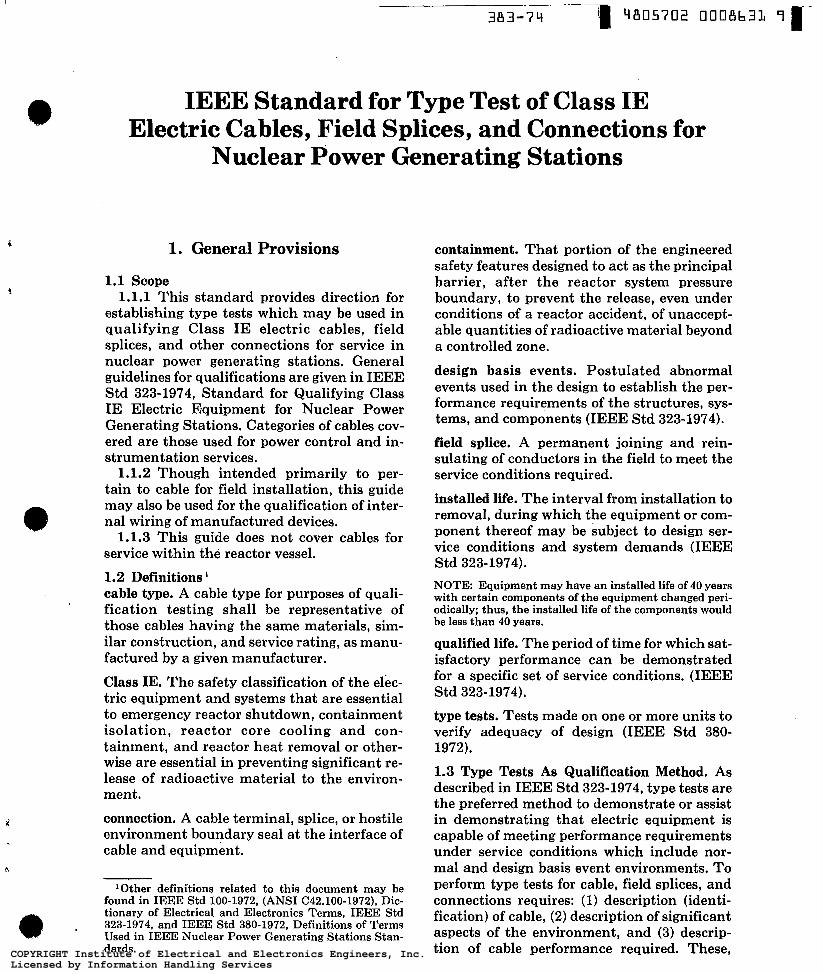
1. General Provisions
1.1 Scope 1.1.1 This standard provides direction for
establishing type tests which may be used in qualifying Class IE electric cables, field splices, and other connections for service in nuclear power generating stations. General guidelines for qualifications are given in IEEE Std 323-1974, Standard for Qualifying Class IE Electric Equipment for Nuclear Power Generating Stations. Categories of cables cov- ered are those used for power control and in- strumentation services.
1.1.2 Though intended primarily to per- tain to cable for field installation, this guide may also be used for the qualification of inter- nal wiring of manufactured devices.
1.1.3 This guide does not cover cables for service within the reactor vessel.
1.2 Definitions cable type. A cable type for purposes of quali- fication testing shall be representative of those cables having the same materials, sim- ilar construction, and service rating, as manu- factured by a given manufacturer.
Class IE. The safety classification of the elec- tric equipment and systems that are essential to emergency reactor shutdown, containment isolation, reactor core cooling and con- tainment, and reactor heat removal or other- wise are essential in preventing significant re- lease of radioactive material to the environ- ment.
e
i connection. A cable terminal, splice, or hostile environment boundary seal at the interface of cable and equipment.
h
'Other definitions related to this document may be found in IEEE Std 100-1972, (ANSI C42.100-1972), Dic- tionary of Electrical and Electronics Terms, IEEE Std 323-1974, and IEEE Std 380-1972, Definitions of Terms Used in IEEE Nuclear Power Generating Stations Stan- dards.
containment. That portion of the engineered safety features designed to act as the principal barrier, after the reactor system pressure boundary, to prevent the release, even under conditions of a reactor accident, of unaccept- able quantities of radioactive material beyond a controlled zone.
design basis events. Postulated abnormal events used in the design to establish the per- formance requirements of the structures, sys- tems, and components (IEEE Std 323-1974).
field splice. A permanent joining and rein- sulating of conductors in the field to meet the service conditions required.
installed life. The interval from installation to removal, during which the equipment or com- ponent thereof may be subject to design ser- vice conditions and system demands (IEEE Std 323-1974). NOTE Equipment may have an installed life of 40 years with certain components of the equipment changed peri- odically; thus, the installed life of the components would be less than 40 years.
qualified life. The period of time for which sat- isfactory performance can be demonstrated for a specific set of service conditions. (IEEE Std 323-1974).
type tests. Tests made on one or more units to verify adequacy of design (IEEE Std 380- 1972).
1.3 Type Tests As Qualification Method. As described in IEEE Std 323-1974, type tests are the preferred method to demonstrate or assist in demonstrating that electric equipment is capable of meeting performance requirements under service conditions which include nor- mal and design basis event environments. To perform type tests for cable, field splices, and connections requires: (1) description (identi- fication) of cable, (2) description of significant aspects of the environment, and (3) descrip- tion of cable performance required. These, COPYRIGHT Institute of Electrical and Electronics Engineers, Inc.
Licensed by Information Handling ServicesCOPYRIGHT Institute of Electrical and Electronics Engineers, Inc.Licensed by Information Handling Services

383-74 4805702 OOOB’b32 O r IEEE Std 383-1974
then, with engineering knowledge and experi- ence in insulating materials and systems form a basis for designing type tests to demonstrate the capabilities. Qualification of one cable may permit extrapolation of results to qualify other cables of the same type, with consid- eration being given to cable dimensions and probable modes of failure.
A sample field splice or connection or both must be type tested with the cable to demon- strate its electrical, mechanical, and chemical compatibility in the environments.
1.3.1 Cable Description. This description or specification should include as a minimum:
1.3.1.1 Conductor - material identi- fication, size, stranding, coating.
1.3.1,2 Insulation - material identi- fication, thickness, method of application.
1.3.1.3 Assembly (multiconductor cables only) - number and arrangement of con- ductors, fillers, binders.
1.3.1.4 Shielding - tapes, extrusions, braids, or others.
1.3.1.5 Covering - jacket or metallic ar- mor or both, material identification, thick- ness, method of application.
1.3.1.6 Characteristics - voltage and temperature rating (normal and emergency). For instrumentation cables - capacitance, attenuation, characteristic impedance, micro- phonics, insulation resistance, as applicable.
1.3.1.7 Identification - manufacturer’s trade name, catalog number.
1.3.2 Field Splice or Connection Description or Both. This description or specification should include as a minimum.:
1.3.2.1 Whether factory or field assem- bled to cable.
1.3.2.2 Conductor connection - type, material identification, and method of assem- bly.
1.3.2.3 Items from Sections 1.3.1.2 through 1.3.1.7.
1.3.3 Description of Significant Environ- mental Conditions. Both normal operating and design basis event conditions, as well as their sequence and duration, are relevant for type testing. Separate requirements for post design basis event conditions may be required in recognition of momentary or accumulative changes in material properties due to aging, radiation, heat, and steam exposure. Environ- mental factors, the limits of which may be sig- nificant to the cable’s operation are as follows:
TYPE TEST OF CLASS IE
age and
1.3.3.1 Atmosphere. Maximum and aver- ambient or normal operation condition e design basis event condition or profile for
the following: (1) Gas composition and velocity (2) Moisture content (3) Temperature (4) Pressure
(1) Normal dose rate and type (2) Total normal installed life dosage (3) Design basis event dose rate. Maximum
(4) Total design basis event dosage (5) Total for the installed life plus design
1.3.3.2 Radiation.
dose rate and approximate profile
basis event 1.3.3.3 Chemicals
(1) Type of chemicals and concentration (2) Spray or immersion rate and time (3) Temperature of exposure
1.3.3.4 Mechanical. Normal operating condition and design basis event condition for the following:
(1) Bending or flexing (2) Vibration (3) Tension (4) Sidewall pressure
1.3.4 Operating Requirements 1.3.3.5 Fire
1.3.4.1 Meeting Service Conditions. The cable, as installed, should be suitable for oper- ation at maximum ambient temperature, radiation, and atmospheric conditions .and normal electrical and physical stresses for its installed life, as specified. Evidence of this suitability may be based on compliance with appropriate published industry standards, past documented operating experience, com- ponent tests, or a combination of these.
The total station may be subdivided into zones with substantially different ambient conditions, and if segregation of cables to cer- tain areas is assured, a cable need only be suit- able for meeting service conditions in those zones in which it is located.
1.3.4.2 Design Basis Event Conditions for Qualifying Cables
1.3.4.2.1 Design Basis Event - Loss- of-Coolant Accident (LOCA) (for cables in containment only). The cable, field splices, and connections should throughout their nor- mal lives be capable of operating through postulated environmental conditions re- COPYRIGHT Institute of Electrical and Electronics Engineers, Inc.
Licensed by Information Handling ServicesCOPYRIGHT Institute of Electrical and Electronics Engineers, Inc.Licensed by Information Handling Services

ELECTRIC CABLES, FIELD SPLICES, AND CONNECTIONS IEEE
Std 383-1974
sulting from a LOCA. Conditions of loading and signal levels shall be assumed to be those most unfavorable for cable operation which may be anticipated under such circumstances.
1.3.4.2.2 Design Basis Event - Fire. The cable should not propagate fire under conditions of installation.
1.3.4.2.3 Other Design Basis Events. These should also be considered in case they represent different types or more severe haz- ards to cable operation. .
1.3.5 Type Test Conditions and Sequences 1.3.5.1 General. Type tests are used pri-
marily to indicate that the cables, field splices, and connections can perform under the conditions of a design basis event. Because the design basis events may occur at any time in the station life, the thermal and radiation aging required in type tests to simulate these conditions may at the same time indicate the ability of cable types to operate under the nor- mal service conditions within the station.
1.3.5.2 Aging. The effect of normal oper- ating conditions with time may either add to or reduce the ability of cable, field splices, and connections to withstand the extreme envi- ronments and loads imposed during and fol- lowing a design basis event. Thus, the type testing for design basis event conditions shall involve both aged and nonaged.samples. Ag- ing pertains to temperature, radiation, and at- mospheric effects applied in sequence or si- multaneously in an accelerated manner.
The basis for establishing time and temper- ature conditions for aging of samples to simu- late their qualified life may be that of Ar- rhenius plotting (IEEE Std 1-1969, General Principles for Temperature Limits in the Rat- ing of Electric Equipment, IEEE Std 98-1972, Guide for the Preparation of Test Procedures for the Thermal Evaluation and Estab- lishment of, Temperature Indices of Solid Electrical Insulating Materials, IEEE Std 99- 1970, Guide for the Preparation of Test Proce- dures for the Thermal Evaluation of Insula- tion Systems for Electric Equipment, and IEEE Std 101-1972, Guide for Statistical Analysis of Thermal Life Test Data) or other method of proven validity and applicability for the materials in question.
1.3.5.3 Test Design Basis Event. Type tests for design basis event conditions should consist of subjecting nonaged and aged cables, field splices, and connections to a sequence of
environmental extremes which simulate the most severe postulated conditions of a design basis event and specified conditions of instal- lation. Type tests shall demonstrate margin by application of multiple transients, in- creased level, or other justifiable means. Satis- factory performance of the cable will be eval- uated by electrical and physical measure- ments appropriate to the type of cable during or following the environmental cycle or both.
The values of pressure, temperature, radi- ation, chemical concentrations, humidity, and time in Section 2 do not represent accept- able limitations for all nuclear power stations. The user of this guide should assure that the values used in the required type tests repre- sent acceptable limits for the service condi- tions in which the cable or connections will be installed.
1.4 Documentation 1.4.1 General. Type test data used to dem-
onstrate the qualification of cables should be organized in an auditable form. The docu- mentation should include:
1.4.1.1 Description or specification of cable.
1.4.1.2 Description or specification of field splice or connection.
1.4.1.3 Identification of the specific envi- ronmental features.
1.4.1.4 Identification of the specific per- formance requirements to be demonstrated.
1.4.1.5 The test program outline. 1.4.1.6 The test results. 1.4.1.7 Approving signature and date.
1.4.2 Test Program Outline. For cable and connections, this outline-shall include:
1.4.2.1 The physical arrangement of the cable and test equipment description.
1.4.2.2 Time program and sequence of all environmental factors.
1.4.2.3 The type and location of all envi- ronmental and cable monitoring sensors for each variable.
1.4.2.4 The voltages or currents pro- grammed in conjunction with Section 1.4.2.1 above.
1.4.2.5 The electrical, thermal, or me- chanical tests to be performed during environ- mental exposure.
1.4.2.6 Testing or examinations sub- sequent to environmental cycle. COPYRIGHT Institute of Electrical and Electronics Engineers, Inc.
Licensed by Information Handling ServicesCOPYRIGHT Institute of Electrical and Electronics Engineers, Inc.Licensed by Information Handling Services

IEEE Std 383-1974
1.4.3 Test Results. Test results should dem- onstrate that:
1.4.3.1 The intended environmental se- quences were achieved.
1.4.3.2 The cable or field splice (or con- nection) or both was capable of performing its intended function.
1.4.4 Test Evaluation. An evaluation of data should be made to demonstrate the ad- equacy of cable performance as outlined in Section 1.4.1.4.
1.5 Modifications. When modification in the materials or design of cables or in the condi- tions of installation or in the postulated envi- ronments are made, prior type tests shall be reviewed to determine the effect on the cable qualification. This evaluation shall indicate whether or not new type tests are required. The analysis of data and evaluation that dem- onstrates the effect of the modification on the equipment performance shall be added .to the qualification documentation.
2. Examples of Type Tests
2.1 Introduction. Type tests described in this document are examples of methods which may be used to qualify electrical cables, field splices and connections for use in nuclear power generating stations. Tests of the 'cable or connection assembly, as applicable, should then supplement the cable tests in order to qualify the connections and other aspects unique to planned usage.
The values of pressure, temperature, radi- ation, chemical concentrations, humidity, and time used do not represent acceptable limits for all nuclear power generating sta- tions. The user of this guide should assure that the values used in the required type tests represent acceptable limits for the service con- ditions in which the cable or connections, or both will be installed.
Results of prior tests that are being used as the bases for the present tests should be refer- enced in the documentation.
2.2 Type Test Samples. The samples tested should contain the conductor, insulation, fill- ers, jacket, binder tape, overall jacket, shield- ing, and field splices which are representative of the cable category being qualified. Table 1
383-74 4805702 0008634 'lr TYPE TEST OF CLASS IE
lists sizes which have been considered repre- sentative of these categories. The sample lengths should be sufficient to permit reliable test readings and evaluation consistent with good testing practice.
2.3 Testing to Qualify for Normal Operation 2.3.1 Temperature and Moisture Resist-
ance. Evidence of qualification for normal op- eration may be demonstrated by providing certified evidence that the cable has been manufactured and tested and passed in accor- dance with the provisions of one or more of the following industry standards or criteria.
ANSI C83.21-1972 Requirements for Solid Dielectric Transmission Lines
ANSI C96.1-1964 (R19691 Temperature Mea- surement Thermocouples
ANSI Cl-1971 National Electrical Code, NFPA 70-1971, Sections on Types RHH, RHW, and XHHW2
IPCEA S-19-81 Rubber-Insulated Cable IPCEA S-66-524 Cross-Linked-Polyethylene-
Insulated Cable IPCEA S-68-516 Interim Standards for Eth-
ylene-Propylene-Rubber-Insulated Wire and Cable. Number 1, Cables Rated 0-35 O00 V. Number 2, Cables Rated 2000 V, Integral Insulation and Jacket.
AEIC 5-71 Specifications for Polyethylene and Cross-Linked-Polyethylene-Insulated, Shielded Power Cables rated 5000- 35 O00 V
AEIC 6-73 Specifications for Ethylene-Propy- lene-Rubber-Insulated Shielded Power Cables Rated 5-46 kV 3; .. 2.'3.2 Long-Term Physical Aging Frq$er-
ties. Aging data should be submitted to estab- lish long-term performance of the insulation. Data may-be evaluated using the Arrhenius technique. A minimum of 3 data points, in- cluding 136 O C and two or more others at least l o o C apart in temperature, should be used.
2.3.3 Thermal and Radiation Exposure. The following test sequence may be used to demonstrate that the cable will be operational after exposure to simulated thermal and radi- ation aging.
"able types RHH, RHW, and XHHW, as specified in the National Electrical Code should meet the re- quirements established by the applicable standards of Underwriters' Laboratories, Inc or other recognized agencies. COPYRIGHT Institute of Electrical and Electronics Engineers, Inc.
Licensed by Information Handling ServicesCOPYRIGHT Institute of Electrical and Electronics Engineers, Inc.Licensed by Information Handling Services
ELECTRIC CABLES, FIELD SPLICES, AND CONNECTIONS
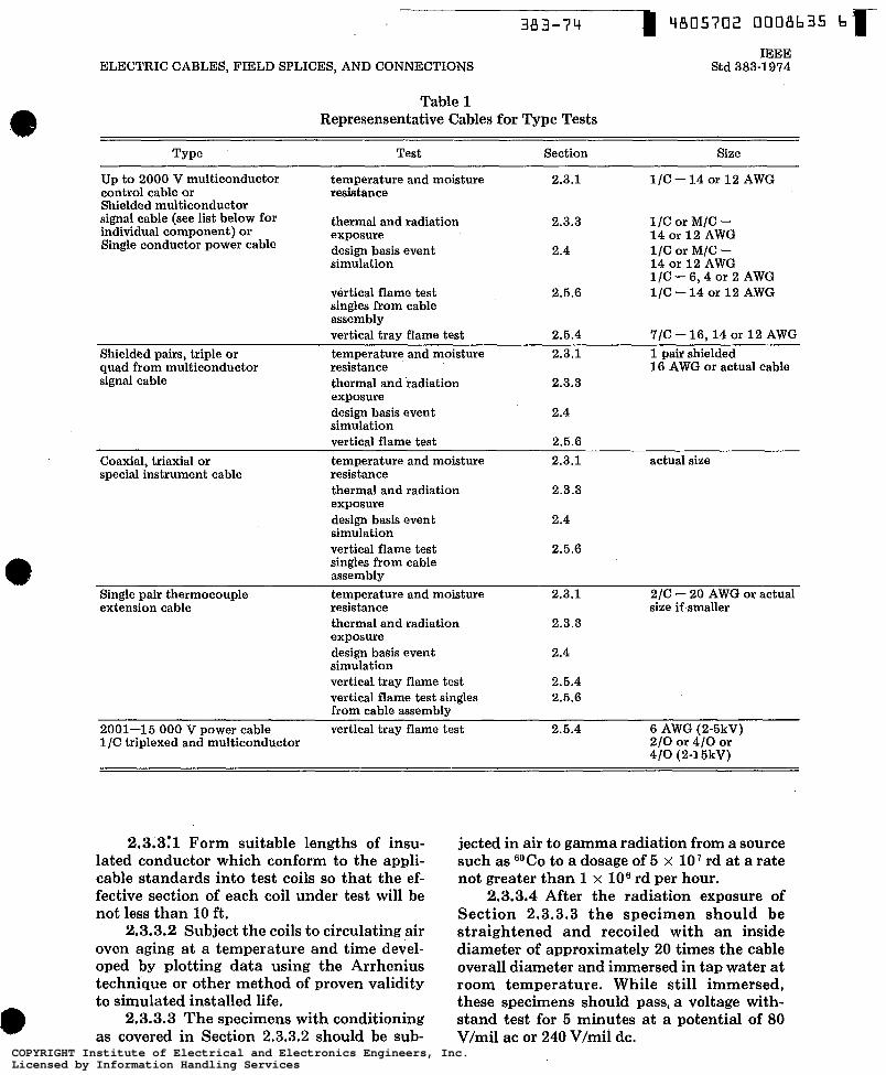
Table 1 Represensentative Cables for Type Tests
IEEE Std 383-1974
Type Test Section Size
Up to 2000 V multiconductor temperature and moisture 2.3.1 1/C -14 or 12 AWG control cable or resistance Shielded multiconductor signal cable (see list below for individual component) or
thermal and radiation 2.3.3 1/C or M/C - Single conductor power cable exposure 14 or 1 2 AWG
design basis event 2.4 1/C or M/C - simulation 14 or 12 AWG
1/C - 6 , 4 OK 2 AWG vertical flame test 2.5.6 1/C - 1 4 OK 1 2 ABG singles from cable assembly vertical tray flame test 2.5.4 7/C - 16,14 or 1 2 AWG
Shielded pairs, triple or temperature and moisture 2.3.1 1 pair shielded quad from multiconductor resistance 1 6 AWG or actual cable signal cable thermal and radiation 2.3.3
exposure design basis event simulation vertical flame test
2.4
2.5.6 Coaxial, triaxial or temperature and moisture 2.3.1 actual size special instrument cable resistance
thermal and radiation 2.3.3 exposure design basis event simulation vertical flame test singles from cable assembly
2.4
2.5.6
Single pair thermocouple temperature and moisture 2.3.1 2/C - 20 AWG or actual extension cable resistance size if smaller
thermal and radiation 2.3.3 exposure design basis event 2.4 simulation vertical tray flame test 2.5.4 vertical flame test singles 2.5.6 from cable assembly
2001-1 5 O00 V power cable vertical tray flame test 2.5.4 6 AWG (2-5kV) 1/C tritdexed and multiconductor 2 / 0 or 410 or
410 (2-15kV)
2.3.3:l Form suitable lengths of insu- lated conductor which conform to the appli- cable standards into test coils so that the ef- fective section of each coil under test will be not less than 10 ft.
2.3.3.2 Subject the coils to circulating air oven aging at a temperature and time devel- oped by plotting data using the Arrhenius technique or other method of proven validity to simulated installed life.
2.3.3.3 The specimens with conditioning as covered in Section 2.3.3.2 should be sub-
jected in air to gamma radiation from a source such as 6oCo to a dosage of 5 x lo7 rd at a rate not greater than 1 x lo6 rd per hour.
2.3.3.4 After the radiation exposure of Section 2.3.3.3 the specimen should be straightened and recoiled with an inside diameter of approximately 20 times the cable overall diameter and immersed in tap water at room temperature. While still immersed, these specimens should pass, a voltage with- stand test for 5 minutes at a potential of 80 V/mil ac or 240 V/mil dc.
COPYRIGHT Institute of Electrical and Electronics Engineers, Inc.Licensed by Information Handling ServicesCOPYRIGHT Institute of Electrical and Electronics Engineers, Inc.Licensed by Information Handling Services
IEEE Std 383-1974
2.4 Testing for Operation During Design Basis Event 2.4.1 General. This section is predicated
upon a loss of coolant accident (LOCA) but not necessarily limited thereto.
Prepare two sets of specimens in accordance with the following.
2.4.1.1 One set to be unaged. 2.4.1.2 The other set to be heat aged
specimens in accordance with Sections 2.3.3.1 and 2.3.3.2.
NOTE: The requirements of Sections 2.3.3.3 and 2.3.3.4 may be omitted if Section 2.4 is followed as a guide since the requirements of Section 2.4 exceed those of Sections 2.3.3.3 and 2.3.3.4.
2.4.2 Radiation Exposure - Total. Ex- posure specimens to the maximum total cum- ulative radiation dosage expected over the in- stalled life (see Section 2.3.3.3) plus one LOCA exposure to radiation for the particular installation involved as covered in IEEE Std 323-1974 Appendix A or B. The rate of ex- posure shall not be greater than 1 x l o6 rd per hour. This restriction is removed when simu- lation of the LOCA profile requires a greater dose rate. 2.4.3 LOCA Simulation. Test irradiated
specimens in a pressure vessel so constructed that the specimens can be operated under rated voltage and load while simultaneously exposed to the pressure, temperature, humid- ity and chemical spray of a LOCA event. Chamber designs should have provisions for monitoring and varyin.g temperature and steam pressure, for recycling chemical spray, and for electrically loading the specimens as specified herein.
2.4.3.1 After conditioned specimens are installed inside the pressure vessel they should be energized at rated voltage and loaded with rated service current while under the average normal operating condition. The energized specimens should be exposed to one cycle of the environmental extremes accord- ing to the schedule postulated for the particu- lar installation, see IEEE Std 323-1974.
2.4.3.2 The cable should function elec- trically throughout its exposure to the envi- ronmental extremes within the specified elec- trical parameters. 2.4.4 Post LOCA Simulation Test. Upon
completion of the LOCA simulation, the spec- imens should be straightened and recoiled
- ~~ " 12
TYPE TEST OF CLASS IE '
around a metal mandrel with a diameter of approximately 40 times the overall cable diameter and immersed in tap water at room temperature. While still immersed, these spec- imens should again pass the same voltage withstand test performed under Section 2.3.3.4. NOTE: The post LOCA simulation test demonstrates an adequate margin of safety by requiring mechanical dura- bility (mandrel bend) following the environmental simu- lation and is more severe than exposure to two cycles of the environment.
2.5 Flame Tests 2.5.1 General. This section describes the
method for type testing of grouped cables via the vertical tray flame test to determine their relative ability to resist fire. 2.5.2 Criteria 2.5.2.1 The fire test should demonstrate
that the cable does not propagate fire even if its outer covering and insulation have been destroyed in the area of flame impingement.
2.5.2.2 The fire test should approximate installed conditions and should provide con- sistent results. 2.5.3 Test Specimens 2.5.3.1 The tests proposed are for power, a
control, and instrumentation cables. 2.5.3.2 Sizes recommended for type tests
may be as listed in Table 1 but not necessarily limited thereto. 2.5.4 Fire Test Facility and Procedure 2.6.4.1 Test should be conducted in a
naturally ventilated room or enclosure free from excessive' drafts and spurious air cur- rents.
2.5.4.2 The vertical tray configuration is recommended as the best arrangement to es- tablish whether or not a cable could propagate a fire. The tray should be a vertical, metal, ladder type, 3 in deep, 12 in wide, and 8 f t long, The tray may be bolted at the bottom to a length of horizontal tray for support.
2.5.4.3 Test sample arrangement - mul- tiple lengths of cable should be arranged in a single layer filling at least the center six inch portion of the tray with a separation of ap- proximately 1/2 the cable diameter between each cable. The test should be conducted 3 times to demonstrate reproducibility using different samples of cable.
2.5.4.4 Flame source, when specified, the procedure detailed below shall be followed:
COPYRIGHT Institute of Electrical and Electronics Engineers, Inc.Licensed by Information Handling ServicesCOPYRIGHT Institute of Electrical and Electronics Engineers, Inc.Licensed by Information Handling Services
383-74 4805702 0008637 0 r ELECTRIC CABLES, FIELD SPLICES, AND CONNECTIONS
IO-in wide, 11 -55 Drilling Ribbon Burner Modified
Optional for Gas Pressure Control
Air-Gas Mixer Natural
Supply Side A Water
Manometer Air Inlet B Compressed air
(oil-free and dry) Air regulator and valve.
NOTE: All pressures measured under dynamic conditions.
A Schematic Drawing
to 8-32 Stud 8-32 Nut Soldered
8-32 Nut Soldered
OD 200 Inch Free Length. 1 Inch Wire Size .O18 Inch
12 Turns Cover Plate Last Turn Formed
to a Point
to 8-32 Stud 8-32 Nut Soldered
8-32 Nut Soldered
OD 200 Inch Free Length. 1 Inch Wire Size .O18 Inch
12 Turns Cover Plate Last Turn Formed
to a Point
B Detail Drawing of Zero Pressure Governor Modification
Fig 1 ,Flame Source
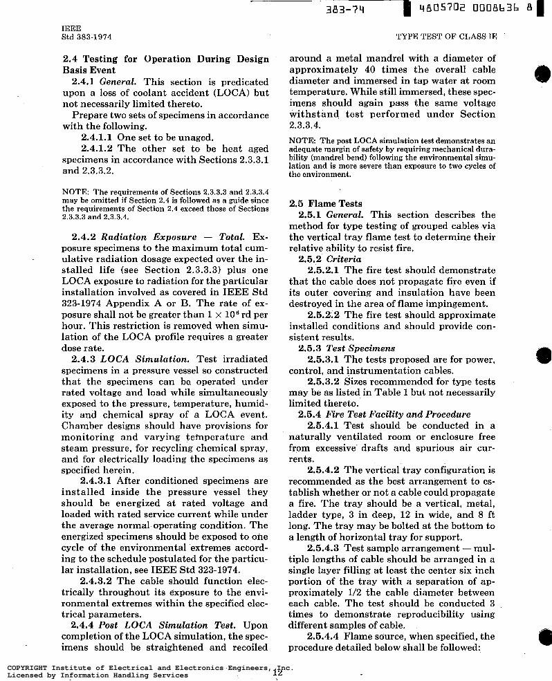
2.5.4.4.1 The ribbon gas burner3 shall be mounted horizontally such that the flame impinges on the specimen midway between the tray rungs, and so that the burner face is 3
SAn American Gas Furnace Co 10 in, 11-55 drilling, rib- bon type, catalog no 1OX 11-56 with an air-gas Venturi mixer, catalog no 14-18 (2 lbf/in2 max gauge pressure) is the only presently available model that has been found satisfactory for purposes of these tests.
13
IEEE Std 383-1974'
in behind and approximately 2 f t above the bottom of the vertical tray. Because of its uni- form heat content natural grade propane is preferred to commercial gas.
2.5.4.4.2 T h e flame temperature should be approximateiy 1500°F when mea- sured by a thermocouple located in the flame close to, but not touching the surface of the test specimens (about l l8 in spacing).
COPYRIGHT Institute of Electrical and Electronics Engineers, Inc.Licensed by Information Handling ServicesCOPYRIGHT Institute of Electrical and Electronics Engineers, Inc.Licensed by Information Handling Services
IEEE Std 383-1974
STEP 1
FOLO CORNERS STEP 3
IN TO CENTER
FOLO CORNERS IN STEP 2
TO CENTER
FOLD IN HALF STEP 4
TYPE TEST OF CLASS IE
STEP I FOLD IN THIRDS; WRAP
EACH AXIS TO RETAIN SHAPE THIN COPPER WIRE AT
NOTE: All dimensions are in inches.
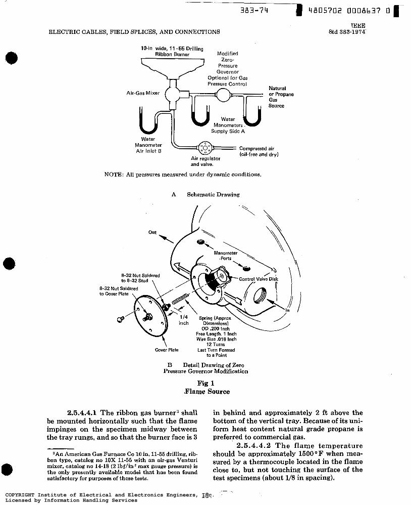
Fig 2 Burlap Folding Sequence
2.5.4.4.3 For the schematic arrange- ment see Fig 1. Under dynamic conditions, if propane gas is used the pressure shall be -2.6*0.3 cm of water at the supply side A to the Venturi mixer. If commercial gas is used the pressure shall be -0.9kO.1 cm of water when measured at the supply side of the Ven- turi mixer. For propane gas, the air pressure should be 4.3*0.5 cm of water. For commer- cial gas it shall be 5.6&0.5 cm of water, mea- sured at the air inlet B to the mixer. In prac- tice the flame length will be approximately 15 in when measured along its path.
2.5.4.4.4 Gas-burner procedure - ig- nite the burner and allow it to burn for 20 minutes. Record temperatures at point of im- pingement throughout the duration of the test, length of time flame continues to burn af- ter gas burner is shut off, jacket char distance, and distance insulation is damaged.
2.6.4.5 Alternative flame source, oil or burlap - when specified, the procedure de- tailed below shall be followed.
2.5.4.6.1 Use a 24 in square piece of 9 oz per square yard burlap, folded as shown in Fig 2 into a bundle 4 in x 4 in x 6 in. Wrap with fine copper wire as shown, to retain the shape of the bundle. Immerse in a container of oil4 for 5 minutes. Remove, hang free in air, allow to drain for approximately 15 minutes. The burlap ignitor is weighed before im- mersion and after draining, and the fuel pick- up should be 1 6 0 4 g. The repeatability of this test is derived from constant fuel pickup in ignitors of constant size and weight. Tem- perature should be monitored at point of max- imum flame impingement upon the test ca- bles.
2.5.4.5.2 After draining, the ignitor should be placed in front of and approximate- ly 2 f t above the bottom of the tray with -the 4 in x 6 in face of the ignitor held in place against thescables by a suitable metal wire or band.
4Such as Mobilect 33.
COPYRIGHT Institute of Electrical and Electronics Engineers, Inc.Licensed by Information Handling ServicesCOPYRIGHT Institute of Electrical and Electronics Engineers, Inc.Licensed by Information Handling Services

383-74
ELECTRIC CABLES, FIELD SPLICES, AND CONNECTIONS
I 4805702 0008637 3 I IEEE
Std 383-1974
2.5.4.5.3 Ignite the oil soaked burlap. The applied flame should be allowed to burn itself out naturally.
2.5.5 Evaluation. Cables which propagate the flame and burn the total height of the tray above the flame source fail the test. Cables which self-extinguish when the flame source is removed or burn out pass the test. Cables which continue to burn after the flame source is shut off or burns out should be allowed to burn in order to determine the extent.
2.6.6 Instrument Cable and Single Con- ductors from Multiconductor Assembly. A specimen of each type of instrument cable or the individually insulated or insulated and jacketed conductors removed from each mul- ticonductor control cable which is type tested should pass a flame resistance test in accor- dance with ASTM D2220-68, Vinyl Chloride Plastic Insulation for Wire and Cable, Section 5 (IPCEA Standard S-19-81, Section 6.19.6), except the weight may be omitted if the speci- men is securely clamped.
. 2.6 Documentation of Type Testing. Follow- ing the procedures outlined in this guide, pro- vide data necessary to document satisfactory compliance. Certification of prior test results will be provided when required.
Section 2.3.1 2.3.2 2.3.3 2.4
2.5.1
2.5.6
IEEE 1 I l
Temperature and Moisture Long-Term Physical Aging Properties Thermal and Radiation Exposure Testing for Operation During Design Basis Event (LOCA) Flame Test on Grouped Cables in Verti- cal Tray Flame Test on Single Conductor
3. References
Std 1-1969, General Principles for Tem-
perature Limits in the Rating of Electric Equipment IEEE Std 98-1972, Guide for the Preparation of Test Procedures for the Thermal Eval- uation, and Establishment of Temperature Indices of Solid Electrical Insulating Materi- als IEEE Std 99-1970, Guide for the Preparation of Test Procedures for the Thermal Eval- uation of Insulation Systems for Electric Equipment
Dictionary of Electrical and Electronics Terms IEEE Std 101-1972, Guide for the Statistical Analysis of Thermal Life Test Data .
IEEE Std 279-1971 (ANSI N42.7-19721, Cri- teria for Protection Systems for Nuclear Pow- er Generating Stations .
IEEE Std 308-1974, IEEE Standard Criteria for Class IE Power Systems for Nuclear Power Generating Stations IEEE Std 317-1971, Electrical Penetration Assemblies in Containment Structures for Nuclear Power Generating Stations IEEE Std 323-1974, Standard for Qualifying Class IE Electric Equipment for Nuclear Power Generating Stations IEEE Std 334-1971, Type Tests of Continuous Duty Class I Motors Installed Inside the Con- tainment of Nuclear Power Generating Sta- tions IEEE Std 336-1972 (ANSI N45.2.4-19721, In- stallation, Inspection, and Testing Require- ments for Instrumentation and Electric Equipment During the Construction of Nu- clear Power Generating Stations IEEE Std 380-1972, Definitions of Terms Used in IEEE Nuclear Power Generating Sta- tions Standards ASTM D2220-68, Vinyl Chloride Plastic Insula- tion for Wire and Cable
IEEE Std 100-1972 (ANSI C42.100-1972),
COPYRIGHT Institute of Electrical and Electronics Engineers, Inc.Licensed by Information Handling ServicesCOPYRIGHT Institute of Electrical and Electronics Engineers, Inc.Licensed by Information Handling Services

IEEE Standards of Particular Interest to Nuclear Engineers and Scientists
IEEE Std Title 278-1967 Guide for Classifying Electrical Insulating Materials Exposed to Neutron
279-1971 Criteria for Protection Systems for Nuclear Power Generating Stations
300-1969 Test Procedure for Semiconductor Radiation Devices (ANSI N42.1-1969) 301-1969 Test Procedure for Amplifiers and Preamplifiers for Semiconductor Radia-
308-1974 Criteria for Class IE Power Systems for Nuclear Power Generating Stations 309-1970 Test Procedure for Geiger-Muller Counters (ANSI N42.3-1969) 317-1972 Electrical Penetration Assemblies in Containment Structures for Nuclear
323-1974 Qualifying Class IE Electric Equipment for Nuclear Power Generating
325-1971 Test Procedure for Germanium Gamma-Ray Detectors (ANSI N42.8-1972) 334-1971 Trial-Use Guide for Type Tests of Continuous Duty Class 1 Motors Installed
Inside the Containment of Nuclear Power Generating Stations (ANSI N41.9)
336-1971 Installation, Inspection, and Testing Requirements for Instrumentation and Electric Equipment During the Construction of Nuclear Power Generating Stations (ANSI N45.2.4-1972)
338-1971 Trial-Use Criteria for the Periodic Testing of Nuclear Power Generating Station Protection Systems (ANSI N41.3)
344-1971 Trial-Use Guide for Seismic Qualification of Class 1 Electric Equipment for Nuclear Power Generating Stations (ANSI N41.7)
352-1972 Trial-Use Guide: General Principles for Reliability Analysis of Nuclear Power Generating Station Protection Systems (ANSI N41.4)
379-1972 Trial-Use Guide for the Application of the Single-Failure Criterion to Nuclear Power Generating Station Protection Systems (ANSI N41.2)
380-1972 Definitions of Terms used in IEEE Standards on Nuclear Power Generating Stations
382-1972 Trial-Use Guide for the Type-Test of Class 1 Electric Valve Operators for Nuclear Power Generating Stations (ANSI N41.6)
383-1974 Standard for Type Test of Class IE Electric Cables, Field Splices, and Con- nections for Nuclear Power Generating Stations
384-1974 Trial-Use Standard Criteria for Separation of Class IE Equipment and Cir- cuits (ANSI N41.14)
387-1972 Trial-Use Criteria for Diesel-Generator Units Applied as Standby Power Supplies for Nuclear Power Generating Stations (ANSI N41.13)
398-1972 Test Procedures for Photomultipliers for Scintillation Counting and Glossary for Scintillation Counting Field (ANSI N42.9-1972)
420-1973 Trial-Use Guide for Class IE Control Switchboards for Nuclear Power Generating Stations (ANSI N41.17)
450-1972 Recommended Practice for Maintenance, Testing, and Replacement of Large Stationary Type Power Plant and Substation Lead Storage Batteries
ANSI N13.4-1971 Specification of Portable X- or Gamma-Radiation Survey Instru-
ANSI N42.4-1971 High Voltage Connectors for Nuclear Instruments ANSI N42.5-1965 Bases for GM Counter Tubes (Reaffirmed 1971) ANSI N42.6-1965 Interrelationship of Quartz-Fiber Electrometer Type Dosimeters
and Gamma Radiation
(ANSI N42.7-1972)
tion Detectors (ANSI N42.2-1969)
Power Generating Stations (ANSI N45.3-1973)
Stations
ments
and Companion Dosimeter Chargers (Reaffirmed 1971)
For a free catalog of IEEE Standards write the
Institute of Electrical and Electronics Engineers, Inc 345 East 47th Street, New York, N. Y. 10017, U.S.A. COPYRIGHT Institute of Electrical and Electronics Engineers, Inc.
Licensed by Information Handling ServicesCOPYRIGHT Institute of Electrical and Electronics Engineers, Inc.Licensed by Information Handling Services