ieee 802.15.4 stack user guide v2 - nxp … · 3.3 start 60 3.3.1 start messages 60 ... ieee...
TRANSCRIPT

IEEE 802.15.4 StackUser Guide
JN-UG-3024
Revision 2.6
22 June 2016

IEEE 802.15.4 StackUser Guide
2 © NXP Laboratories UK 2016 JN-UG-3024 v2.6

IEEE 802.15.4 StackUser Guide
Contents
Preface 11Organisation 11
Conventions 12
Acronyms and Abbreviations 12
Related Documents 13
Support Resources 14
Trademarks 14
Chip Compatibility 14
Part I: Concept and Operational Information
1. Introduction to IEEE 802.15.4 171.1 IEEE 802.15.4 Background and Context 17
1.1.1 Motivation for Standard 17
1.1.2 Application Areas 18
1.2 Radio Frequencies and Data Rates 19
1.3 Achieving Low Power Consumption 20
1.4 Network Topologies 211.4.1 Star Topology 22
1.4.2 Tree Topology 23
1.4.3 Mesh Topology 24
1.5 Device Types 25
1.6 Device Addressing 25
1.7 Network Set-up 26
1.8 Data Transfer 281.8.1 Data Frames and Acknowledgements 28
1.8.2 Data Transfer Types 29
1.9 Software Stack Architecture 301.9.1 Physical (PHY) Layer 31
1.9.2 Media Access Control (MAC) Sub-layer 31
1.10 Channel Management 321.10.1 Channel Assignment 32
1.10.2 Clear Channel Assessment (CCA) 34
1.10.3 Channel Rejection 34
1.11 Device Management 351.11.1 PAN Co-ordinator Selection 35
1.11.2 Device Association and Disassociation 35
1.11.3 Orphan Devices 36
JN-UG-3024 v2.6 © NXP Laboratories UK 2016 3

Contents
1.12 Beacon and Non-beacon Enabled Operation 361.12.1 Beacon Enabled Mode 36
1.12.2 Non-beacon Enabled Mode 37
1.13 Routing 381.13.1 Routing in a Star Topology 38
1.13.2 Routing in a Tree Topology 38
1.13.3 Routing in a Mesh Topology 38
1.14 PAN Information Base (PIB) 39
1.15 MAC Interface Mechanism 391.15.1 Service Primitives 39
1.15.2 Blocking and Non-Blocking Operation 40
1.15.3 Callback Mechanism 41
1.15.4 Implementation of Service Primitives 42
1.16 Security 441.16.1 ACL Mode 44
1.16.2 Secured Mode 44
2. IEEE 802.15.4 Software 472.1 Software Overview 47
2.2 Application Programming Interfaces (APIs) 482.2.1 802.15.4 Stack API 48
2.2.2 Integrated Peripherals API 48
2.2.3 Board API 48
2.2.4 Application Queue API (Optional) 49
2.3 Software Installation 492.3.1 JN516x IEEE 802.15.4 SDK 49
2.3.2 JN517x IEEE 802.15.4 SDK 50
2.4 Interrupts and Callbacks 51
3. Network and Node Operations 533.1 MAC Reset 53
3.1.1 Reset Messages 533.1.1.1 Reset Request 533.1.1.2 Reset Confirm 53
3.1.2 Reset Example 53
3.2 Channel Scan 543.2.1 Scan Types 54
3.2.1.1 Energy Detect Scan 543.2.1.2 Active Scan 543.2.1.3 Passive Scan 553.2.1.4 Orphan Scan 55
3.2.2 Scan Messages 553.2.2.1 Scan Request 553.2.2.2 Scan Confirm 563.2.2.3 Orphan Indication 56
4 © NXP Laboratories UK 2016 JN-UG-3024 v2.6

IEEE 802.15.4 StackUser Guide
3.2.2.4 Orphan Response 563.2.2.5 Comm Status Indication 56
3.2.3 Scan Examples 573.2.3.1 Active Scan Example 573.2.3.2 Energy Detect Scan Example 58
3.3 Start 603.3.1 Start Messages 60
3.3.1.1 Start Request 603.3.1.2 Start Confirm 60
3.3.2 Start Example 60
3.4 Synchronisation 613.4.1 Initialising Synchronisation 61
3.4.2 Conflict Notification 62
3.4.3 Sync Messages 623.4.3.1 Sync Request 623.4.3.2 Sync Loss Indication 62
3.5 Beacons and Polling 623.5.1 Beacon Notify Indication 63
3.5.2 Poll Messages 633.5.2.1 Poll Request 633.5.2.2 Poll Confirm 63
3.5.3 Beacon Examples 63
3.5.4 Polling Example 64
3.6 Association 653.6.1 Associate Messages 65
3.6.1.1 Associate Request 653.6.1.2 Associate Confirm 663.6.1.3 Associate Indication 663.6.1.4 Associate Response 663.6.1.5 Comm Status Indication 66
3.6.2 Association Examples 66
3.7 Disassociate 703.7.1 Disassociate Request 71
3.7.2 Disassociate Confirm 71
3.7.3 Disassociate Indication 71
3.7.4 Disassociation Examples 71
3.8 Data Transmission and Reception 723.8.1 Transmission Power 72
3.8.2 Data Request 73
3.8.3 Data Confirm 73
3.8.4 Data Indication 73
3.8.5 Purge Request 74
3.8.6 Purge Confirm 74
3.8.7 Data Transfer Examples 74
3.8.8 Receive Enable 77
3.8.9 Receive Enable Request 77
3.8.10 Receive Enable Confirm 78
JN-UG-3024 v2.6 © NXP Laboratories UK 2016 5

Contents
3.8.11 Receive Enable Examples 78
3.9 Guaranteed Time Slot (GTS) 793.9.1 GTS Request 79
3.9.2 GTS Confirm 79
3.9.3 GTS Indication 79
3.9.4 GTS Examples 80
3.10 PIB Access 823.10.1 MAC PIB Attributes 82
3.10.2 PHY PIB Attributes 83
3.11 Issuing Service Primitives 833.11.1 Sending Requests 83
3.11.2 Registering Deferred Confirm/Indication Callbacks 84
4. Application Development 854.1 Application Templates 85
4.2 Coding for PAN Co-ordinator 86
4.3 Coding for End Device 88
Part II: Reference Information
5. API Functions 935.1 Network to MAC Layer Functions 93
vAppApiMlmeRequest 94
vAppApiMcpsRequest 95
vAppApiSetSecurityMode 96
vAppApiSetHighPowerMode 97
vAppApiSetComplianceLimits 98
5.2 MAC to Network Layer Functions 100u32AppApiInit 101
vAppApiSaveMacSettings 102
vAppApiRestoreMacSettings 103
5.3 MAC Layer PIB Access Functions 104MAC_vPibSetMaxCsmaBackoffs 105
MAC_vPibSetMinBe 106
MAC_vPibSetPanId 107
MAC_vPibSetPromiscuousMode 108
MAC_vPibSetRxOnWhenIdle 109
MAC_vPibSetShortAddr 110
5.4 PHY Layer PIB Access Functions 111eAppApiPlmeGet 112
eAppApiPlmeSet 113
5.5 Callback Functions 114psMlmeDcfmIndGetBuf 115
6 © NXP Laboratories UK 2016 JN-UG-3024 v2.6

IEEE 802.15.4 StackUser Guide
vMlmeDcfmIndPost 116
psMcpsDcfmIndGetBuf 118
vMcpsDcfmIndPost 119
5.6 Status Returns 121
6. Structures 1236.1 MLME Structures 123
6.1.1 MAC_MlmeReqRsp_s 123
6.1.2 MAC_MlmeReqRspParam_u 124
6.1.3 MAC_MlmeDcfmInd_s 125
6.1.4 MAC_MlmeDcfmIndParam_u 126
6.1.5 MAC_MlmeSyncCfm_s 128
6.1.6 MAC_MlmeSyncCfmParam_u 128
6.1.7 MAC_MlmeReqAssociate_s 130
6.1.8 MAC_MlmeReqDisassociate_s 131
6.1.9 MAC_MlmeReqGet_s 132
6.1.10 MAC_MlmeReqGts_s 132
6.1.11 MAC_MlmeReqReset_s 133
6.1.12 MAC_MlmeReqRxEnable_s 133
6.1.13 MAC_MlmeReqScan_s 133
6.1.14 MAC_MlmeReqSet_s 134
6.1.15 MAC_MlmeReqStart_s 135
6.1.16 MAC_MlmeReqSync_s 136
6.1.17 MAC_MlmeReqPoll_s 136
6.1.18 MAC_MlmeReqVsExtAddr_s 137
6.1.19 MAC_MlmeRspAssociate_s 137
6.1.20 MAC_MlmeRspOrphan_s 137
6.1.21 MAC_MlmeCfmScan_s 138
6.1.22 MAC_MlmeCfmGts_s 139
6.1.23 MAC_MlmeCfmAssociate_s 140
6.1.24 MAC_MlmeCfmDisassociate_s 141
6.1.25 MAC_MlmeCfmPoll_s 142
6.1.26 MAC_MlmeCfmRxEnable_s 143
6.1.27 MAC_MlmeCfmGet_s 143
6.1.28 MAC_MlmeCfmSet_s 144
6.1.29 MAC_MlmeCfmStart_s 144
6.1.30 MAC_MlmeCfmReset_s 145
6.1.31 MAC_MlmeCfmVsRdReg_s 145
6.1.32 MAC_MlmeIndAssociate_s 145
6.1.33 MAC_MlmeIndDisassociate_s 146
6.1.34 MAC_MlmeIndGts_s 147
6.1.35 MAC_MlmeIndBeacon_s 147
6.1.36 MAC_MlmeIndSyncLoss_s 148
6.1.37 MAC_MlmeIndCommStatus_s 149
6.1.38 MAC_MlmeIndOrphan_s 150
JN-UG-3024 v2.6 © NXP Laboratories UK 2016 7

Contents
6.2 MCPS Structures 1516.2.1 MAC_McpsReqRsp_s 151
6.2.2 MAC_McpsReqRspParam_u 151
6.2.3 MAC_McpsSyncCfm_s 152
6.2.4 MAC_McpsSyncCfmParam_u 152
6.2.5 MAC_McpsReqData_s 153
6.2.6 MAC_McpsReqPurge_s 153
6.2.7 MAC_McpsCfmData_s 153
6.2.8 MAC_McpsCfmPurge_s 154
6.2.9 MAC_McpsDcfmInd_s 155
6.2.10 MAC_McpsDcfmIndParam_u 155
6.2.11 MAC_McpsIndData_s 156
6.3 Other Structures 1566.3.1 MAC_ScanList_u 156
6.3.2 MAC_PanDescr_s 157
6.3.3 MAC_Addr_s 158
6.3.4 MAC_Addr_u 159
6.3.5 MAC_ExtAddr_s 159
6.3.6 MAC_TxFrameData_s 159
6.3.7 MAC_RxFrameData_s 160
6.3.8 MAC_DcfmIndHdr_s 161
6.3.9 MAC_KeyDescriptor_s 162
6.3.10 MAC_KeyIdLookupDescriptor_s 163
6.3.11 MAC_KeyDeviceDescriptor_s 163
6.3.12 MAC_KeyUsageDescriptor_s 164
6.3.13 MAC_DeviceDescriptor_s 165
6.3.14 MAC_SecurityLevelDescriptor_s 166
7. Enumerations 1697.1 MAC Enumerations 169
7.1.1 MAC PIB Attribute Enumerations 169
7.1.2 MAC Operation Status Enumerations 170
7.2 PHY Enumerations 1717.2.1 PHY PIB Attribute Enumerations 171
7.2.2 PHY PIB Operation Status Enumerations 171
7.3 MLME Enumerations 1727.3.1 MLME Request and Response Type Enumerations 172
7.3.2 MLME Deferred Confirm and Indication Type Enumerations 172
7.3.3 MLME Synchronous Confirm Status Enumerations 173
7.3.4 MLME Scan Type Enumerations 174
7.4 MCPS Enumerations 1747.4.1 MCPS Request and Response Type Enumerations 174
7.4.2 MCPS Indication Type Enumerations 174
7.4.3 MCPS Synchronous Confirm Status Enumerations 175
8 © NXP Laboratories UK 2016 JN-UG-3024 v2.6

IEEE 802.15.4 StackUser Guide
8. PIB Attributes 1778.1 MAC PIB Attributes 177
8.1.1 MAC PIB Write Access using API Functions 179
8.1.2 MAC PIB Examples 180
8.2 PHY PIB Attributes 180
8.3 MAC PIB Security Attributes (Optional) 182
Part III: Appendices
A. Application Queue API 187A.1 Architecture 187A.2 Purpose 188A.3 Functions 188
u32AppQApiInit 189
psAppQApiReadMlmeInd 190
psAppQApiReadMcpsInd 191
psAppQApiReadHwInd 192
vAppQApiReturnMlmeIndBuffer 193
vAppQApiReturnMcpsIndBuffer 194
vAppQApiReturnHwIndBuffer 195
B. Notes on IEEE 802.15.4-2006 Security 197B.1 Security Features 197B.2 Security Procedures and Examples 199B.3 Performance Considerations 202
B.3.1 Memory Usage 202
B.3.2 Frame Size 202
B.3.3 Conclusion 202
JN-UG-3024 v2.6 © NXP Laboratories UK 2016 9

Contents
10 © NXP Laboratories UK 2016 JN-UG-3024 v2.6
IEEE 802.15.4 StackUser Guide
Preface
This manual provides a single point of reference for information on the IEEE 802.15.4 wireless network protocol stack which can be implemented on the NXP JN516x and JN517x families of wireless microcontrollers. The manual introduces the IEEE 802.15.4 standard (2006) and details the NXP 802.15.4 Stack Application Programming Interface (API) which can be used to design wireless network applications for the JN516x/7x devices.
Organisation
This manual is divided into three parts:
Part I: Concept and Operational Information comprises four chapters:
Chapter 1 introduces the IEEE 802.15.4 wireless network protocol, describing the main concepts and features
Chapter 2 introduces the NXP software for implementing wireless networks using the IEEE 802.15.4 protocol
Chapter 3 describes the main operations that may be performed on IEEE 802.15.4 network nodes, with references to the relevant NXP software resources
Chapter 4 provides guidance on IEEE 802.15.4 application development
Part II: Reference Information comprises four chapters:
Chapter 5 details the functions of the NXP 802.15.4 Stack API, as well as the user-defined callback functions that are required
Chapter 6 details the structures of the NXP 802.15.4 Stack API
Chapter 7 lists the enumerations of the NXP 802.15.4 Stack API
Chapter 8 lists and details the PAN Information Base (PIB) attributes
Part III: Appendices contains an appendix describing the optional Application Queue API, which can be used to handle stack and hardware interrupts, and an appendix providing notes on IEEE 802.15.4-2006 security.
JN-UG-3024 v2.6 © NXP Laboratories UK 2016 11

Preface
Conventions
Files, folders, functions and parameter types are represented in bold type.
Function parameters are represented in italics type.
Code fragments are represented in the Courier New typeface.
Acronyms and Abbreviations
ACL Access Control List
ADC Analogue-to-Digital Converter
AES Advanced Encryption Standard
API Application Programming Interface
ASK Amplitude Shift Keying
BPSK Binary Phase-Shift Keying
CAP Contention Access Period
CCA Clear Channel Assessment
CFP Contention Free Period
CPU Central Processing Unit
CSMA/CA Carrier Sense Multiple Access/Collision Avoidance
CTS Clear-To-Send
DAC Digital-to-Analogue Converter
DIO Digital Input Output
This is a Tip. It indicates useful or practical information.
This is a Note. It highlights important additional information.
This is a Caution. It warns of situations that may result in equipment malfunction or damage.
12 © NXP Laboratories UK 2016 JN-UG-3024 v2.6

IEEE 802.15.4 StackUser Guide
FFD Full Function Device
FIFO First-In, First-Out (queue)
GTS Guaranteed Time-Slot
HVAC Heating, Ventilation and Air-Conditioning
LLC Logical Link Control
LPRF Low-Power Radio Frequency
MAC Media Access Control
MIC Message Integrity Code
O-QPSK Offset Quadrature Phase Shift Keying
PAN Personal Area Network
PHY Physical (layer)
PIB PAN Information Base
PWM Pulse Width Modulation
RF Radio Frequency
RFD Reduced Function Device
RTS Ready-To-Send
SDK Software Developer’s Kit
SPI Serial Peripheral Interface
UART Universal Asynchronous Receiver Transmitter
WPAN Wireless Personal Area Network
Related Documents
JN516x
JN-AN-1174 IEEE 802.15.4 Application Template for JN516x
JN-AN-1180 802.15.4 Home Sensor Demonstration for JN516x
JN-UG-3098 BeyondStudio for NXP Installation and User Guide
JN-UG-3087 JN516x Integrated Peripherals API User Guide
JN517x
JN-AN-1211* IEEE 802.15.4 Application Template for JN517x
JN-UG-3109 JN517x LPCXpresso Installation and User Guide
JN-UG-3118 JN517x Integrated Peripherals API User Guide
* JN-AN-1211 is supplied in the JN517x IEEE 802.15.4 SDK (JN-SW-4263)
JN-UG-3024 v2.6 © NXP Laboratories UK 2016 13

Preface
General
SS95552 IEEE 802.15.4 Standard (2006) [from www.ieee.com]
JN-UG-3099 JN51xx Production Flash Programmer User Guide
JN-RM-2003 LPRF Board API Reference Manual
Support Resources
To access online support resources such as SDKs, Application Notes and User Guides, visit the Wireless Connectivity area of the NXP web site:
www.nxp.com/products/interface-and-connectivity/wireless-connectivity
All NXP resources referred to in this manual can be found at the above address, unless otherwise stated.
Trademarks
All trademarks are the property of their respective owners.
Chip Compatibility
The device software described in this manual can be used on the NXP JN516x and JN517x families of wireless microcontrollers. These chip families are often referred to as JN516x/7x devices in this manual.
14 © NXP Laboratories UK 2016 JN-UG-3024 v2.6

IEEE 802.15.4 StackUser Guide
Part I: Concept and Operational
Information
JN-UG-3024 v2.6 © NXP Laboratories UK 2016 15

16 © NXP Laboratories UK 2016 JN-UG-3024 v2.6

IEEE 802.15.4 StackUser Guide
1. Introduction to IEEE 802.15.4
IEEE 802.15.4 is a wireless network protocol which has become an industry-standard for implementing radio-based Personal Area Networks (PANs). This chapter introduces the essential features of the standard.
1.1 IEEE 802.15.4 Background and Context
This section provides useful background information relating to the rationale behind the IEEE 802.15.4 standard and the main application areas that it benefits.
1.1.1 Motivation for Standard
The 802.15.4 standard was introduced by the IEEE to fill a niche left by the existing wireless network standards, which included:
IEEE 802.15.1: Bluetooth, which is a relatively low-power, low-rate wireless network technology, intended for point-to-point communications
IEEE 802.15.3: High-rate WPAN (Wireless Personal Area Network)
High-rate WPAN was driven by applications requiring high data-rates and/or wide spatial coverage, often involving complex solutions with non-trivial power requirements. However, not all applications have such demanding needs - some network applications involve the infrequent exchange of relatively small amounts of data over restricted areas (for example, a home temperature monitoring and control network). Such applications are diverse in nature and represent considerable market potential. Bluetooth was not designed for multiple-node networks, and therefore the IEEE devised a WPAN standard based on a new set of criteria:
Very low complexity
Ultra low power consumption
Low data-rate
Relatively short radio communication range
Use of unlicensed radio bands
Easy installation
Low cost
The IEEE 802.15.4 standard was born.
A central feature of the standard is the requirement for extremely low power consumption. The motivation for this strict power requirement is to enable the use of battery-powered network devices that are completely free of cabling (no network or power cables), allowing them to be installed easily and cheaply (no costly cable installation needed), possibly in locations where cables would be difficult or impossible to install. However, low power consumption necessitates short ranges.
The NXP implementation of IEEE 802.15.4 is currently based on the 2006 standard.
JN-UG-3024 v2.6 © NXP Laboratories UK 2016 17

Chapter 1Introduction to IEEE 802.15.4
1.1.2 Application Areas
The applications of IEEE 802.15.4-based networks are wide ranging, covering both industrial and domestic use. Essentially, for IEEE 802.15.4 to be used in a networking solution, the required data-rate must be low ( 250 kbps) and the maximum range for communicating devices must be short. In addition, a device with an autonomous power supply (no power cables) must have an extremely low power consumption. If these criteria are met, IEEE 802.15.4 may provide the ideal networking solution, particularly when cost and installation are significant issues.
A number of fields of application of IEEE 802.15.4 are described below.
Home Automation and Security: A wireless PAN provides a low-cost solution for electronic control within the home; e.g. HVAC (heating, ventilation and air-conditioning), lighting, curtains/blinds, doors, locks, home entertainment systems. Another important application within the home is security - both intruder and fire detection.
Consumer products: Wireless PANs can be built into consumer electronics products. The most obvious example is to provide a common remote control for the various components of a home entertainment system (that may be distributed throughout the home). Other examples are computer systems and toys, in which a wireless radio link may be used to replace a point-to-point cable link (such as between a mouse and a PC).
Healthcare: This field employs sensors and diagnostic devices that can be networked by means of a wireless PAN. Applications include monitoring during healthcare programmes such as fitness training, in addition to medical applications.
Vehicle Monitoring: Vehicles usually contain many sensors and diagnostic devices, and provide ideal applications for wireless PANs. A prime example is the use of pressure sensors in tyres, which cannot be connected by cables.
Agriculture: Wireless PANs can help farmers monitor land and environmental conditions in order to optimise their crop yields. Such networks can operate at very low data-rates and latencies, but require wide geographical coverage - the latter issue is addressed by using network topologies that allow the relaying of messages across the network.
18 © NXP Laboratories UK 2016 JN-UG-3024 v2.6
IEEE 802.15.4 StackUser Guide
1.2 Radio Frequencies and Data Rates
IEEE 802.15.4 was designed to operate in unlicensed radio frequency bands (although regulations normally still apply concerning the RF output envelope and possibly the duty cycle of a device operating in these bands). The unlicensed RF bands are not the same in all territories of the world, but IEEE 802.15.4 employs three possible bands, at least one of which should be available in a given territory. The three bands are centred on the following frequencies: 868, 915 and 2400 MHz.
The 868-MHz and 915-MHz bands are available with different modulation schemes - BPSK, O-QPSK and ASK (the standard scheme is BPSK). These schemes give rise to different data-rates.
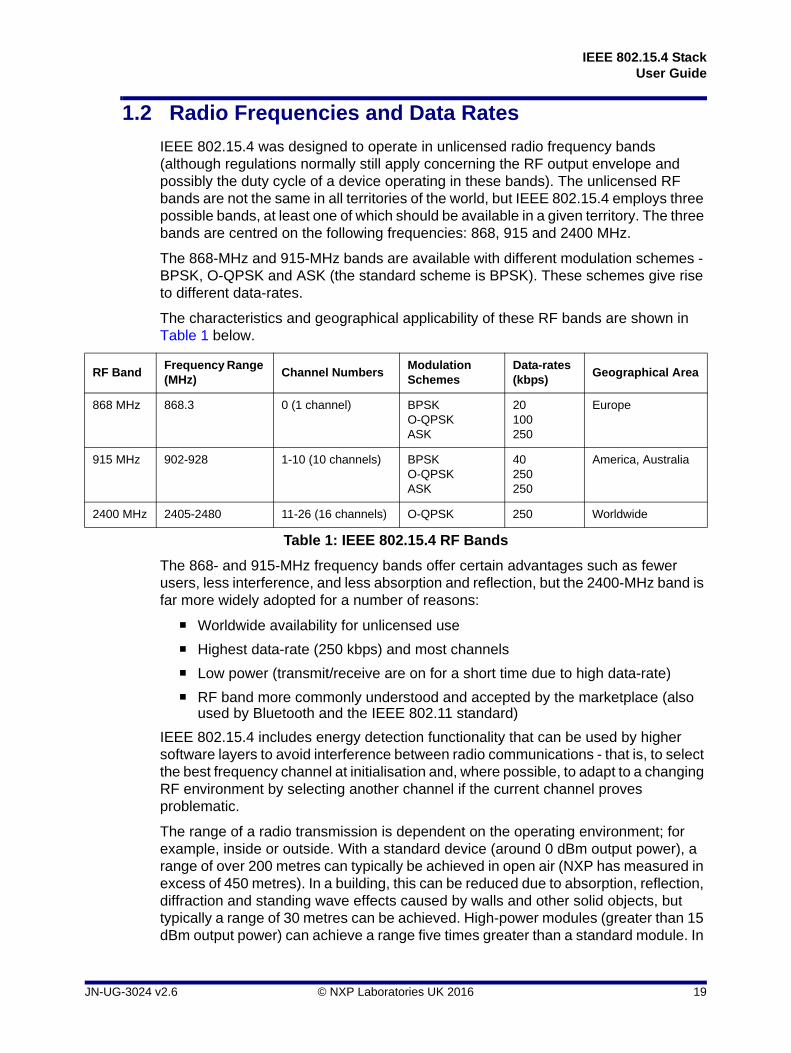
The characteristics and geographical applicability of these RF bands are shown in Table 1 below.
The 868- and 915-MHz frequency bands offer certain advantages such as fewer users, less interference, and less absorption and reflection, but the 2400-MHz band is far more widely adopted for a number of reasons:
Worldwide availability for unlicensed use
Highest data-rate (250 kbps) and most channels
Low power (transmit/receive are on for a short time due to high data-rate)
RF band more commonly understood and accepted by the marketplace (also used by Bluetooth and the IEEE 802.11 standard)
IEEE 802.15.4 includes energy detection functionality that can be used by higher software layers to avoid interference between radio communications - that is, to select the best frequency channel at initialisation and, where possible, to adapt to a changing RF environment by selecting another channel if the current channel proves problematic.
The range of a radio transmission is dependent on the operating environment; for example, inside or outside. With a standard device (around 0 dBm output power), a range of over 200 metres can typically be achieved in open air (NXP has measured in excess of 450 metres). In a building, this can be reduced due to absorption, reflection, diffraction and standing wave effects caused by walls and other solid objects, but typically a range of 30 metres can be achieved. High-power modules (greater than 15 dBm output power) can achieve a range five times greater than a standard module. In
RF BandFrequency Range (MHz)
Channel NumbersModulation Schemes
Data-rates (kbps)
Geographical Area
868 MHz 868.3 0 (1 channel) BPSKO-QPSKASK
20100250
Europe
915 MHz 902-928 1-10 (10 channels) BPSKO-QPSKASK
40250250
America, Australia
2400 MHz 2405-2480 11-26 (16 channels) O-QPSK 250 Worldwide
Table 1: IEEE 802.15.4 RF Bands
JN-UG-3024 v2.6 © NXP Laboratories UK 2016 19

Chapter 1Introduction to IEEE 802.15.4
addition, the range between devices can be extended in an IEEE 802.15.4-based network by employing a topology that uses intermediate nodes as stepping stones when passing data to the destination.
1.3 Achieving Low Power Consumption
An important criterion of the IEEE 802.15.4 standard is the provision for producing autonomous, low-powered devices. Such devices may be battery-powered or solar powered, and require the ability to go to sleep or shut down. There are many wireless applications that require this type of device, from light-switches, active tags and security detectors to solar-powered monitoring.
From a user perspective, battery power has certain advantages:
Easy and low-cost installation of devices: No need to connect to separate power supply
Flexible location of devices: Can be installed in difficult places where there is no power supply, and can even be used as mobile devices
Easily modified network: Devices can easily be added or removed, on a temporary or permanent basis
A typical battery-powered network device presents significant technical challenges for battery usage. Since these devices are generally small, they use low-capacity batteries. Infrequent device maintenance is often another requirement, meaning long periods between battery replacement and the need for long-life batteries. Battery use must therefore be carefully managed to make optimum use of very limited power resources over an extended period of time.
Low duty cycle: Most of the power consumption of a wireless network device corresponds to the times when the device is transmitting. The transmission time as a proportion of the time interval between transmissions is called the duty cycle. Battery use is optimised in IEEE 802.15.4 devices by using extremely low duty cycles, so that the device is transmitting for a very small fraction of the time. This is helped by making the transmission times short and the time interval between transmissions long. In all cases, when not transmitting, the device should revert to a low-power sleep mode to minimise power consumption.
Modulation: The modulation schemes used to transmit data (see Section 1.2) minimise power consumption by using a peak-to-average power ratio of one.
A network device can also potentially use "energy harvesting" to absorb and store energy from its surroundings - for example, the use of a solar cell panel on a device in a well-lit environment.
20 © NXP Laboratories UK 2016 JN-UG-3024 v2.6
IEEE 802.15.4 StackUser Guide
1.4 Network Topologies
A variety of network topologies are possible with IEEE 802.15.4. A network must consist of a minimum of two devices, of which one device must act as the network co-ordinator, referred to as the PAN Co-ordinator.
The possible network topologies are:
Star topology
Tree topology
Mesh topology
These are described below.
Note: In practice, not all devices in a network can be battery-powered, particularly those that need to be switched on all the time (and cannot sleep), such as Co-ordinators. Such devices can often be installed in a mains-powered appliance that is permanently connected to the mains supply (even if not switched on); for example, a ceiling lamp or an electric radiator. This avoids the need to install a dedicated mains power connection for the network device.
Note: The described topologies are not part of the IEEE 802.15.4 standard. In these topologies, message propagation is handled by software above the IEEE 802.15.4 layers, such as ZigBee. The descriptions of topologies (and associated routing) in this manual are therefore included only to illustrate the potential forms of an 802.15.4-based network.
JN-UG-3024 v2.6 © NXP Laboratories UK 2016 21

Chapter 1Introduction to IEEE 802.15.4
1.4.1 Star Topology
The basic type of network topology is the Star topology.
A Star topology consists of a central PAN Co-ordinator surrounded by the other nodes of the network, often referred to as End Devices. Each of these nodes can communicate only with the PAN Co-ordinator. Therefore, to send a message from one node to another, the message must be sent via the Co-ordinator, which relays the message to the destination node. The application program in the Co-ordinator is responsible for relaying messages.
The Star topology is illustrated in Figure 1 below.
A disadvantage of this topology is that there is no alternative route if the RF link fails between the PAN Co-ordinator and the source or target node. In addition, the PAN Co-ordinator can be a bottleneck and cause congestion.
Figure 1: Star Topology
End Device
PAN Co-ordinator
End Device
End Device
End Device
End Device
End Device
22 © NXP Laboratories UK 2016 JN-UG-3024 v2.6

IEEE 802.15.4 StackUser Guide
1.4.2 Tree Topology
The Tree network topology has a structure based on parent-child relationships. Each node (except the PAN Co-ordinator) has a parent. The node (including the PAN Co-ordinator) may also (but not necessarily) have one or more children. Each node can communicate only with its parent and its children (if any). Any node which is a parent acts as a local Co-ordinator for its children.
The network can be visualised as a tree-like structure with the PAN Co-ordinator at the root (at the top). This is illustrated in Figure 2 below.
A special case of the Tree topology is the Cluster Tree topology, in which a given parent-children group is regarded as a cluster, each with its own cluster ID. This is illustrated in Figure 3 below.
Figure 2: Tree Topology
Note: In other wireless network protocols that use 802.15.4 to transport data (such as ZigBee and JenNet), the local Co-ordinators are called Routers.
End Device
PAN Co-ordinator
Co-ordinator
End Device
End Device
End Device
End Device
End Device
End Device
End DeviceEnd Device
Co-ordinator
Co-ordinator
JN-UG-3024 v2.6 © NXP Laboratories UK 2016 23

Chapter 1Introduction to IEEE 802.15.4
1.4.3 Mesh Topology
In the Mesh network topology, the devices can be identical (except one must have the capability to act as the PAN Co-ordinator) and are deployed in an ad hoc arrangement (with no particular network structure). Some (if not all) nodes can communicate directly. Not all nodes may be within range of each other, but a message can be passed from one node to another until it reaches its final destination.
The Mesh topology is illustrated in Figure 4 below.
Alternative routes may be available to some destinations, allowing message delivery to be maintained in the case of an RF link failure.
Figure 3: Cluster Tree Topology
Figure 4: Mesh Topology
Cluster 0
Cluster 1
Cluster 2
Cluster 3
PANCo-ordinator
24 © NXP Laboratories UK 2016 JN-UG-3024 v2.6

IEEE 802.15.4 StackUser Guide
1.5 Device Types
The nodes of an IEEE 802.15.4 based network are of the following general types, which depend on their roles in the network:
PAN Co-ordinator: There must be one and only one PAN Co-ordinator. Its roles include:
Assigning a PAN ID to the network
Finding a suitable radio frequency for network operation
Assigning a short address to itself
Handling requests from other devices to join the network
Relaying messages from one node to another (but not in all topologies)
(Local) Co-ordinator: A Tree network can have one or more local Co-ordinators (as well as a PAN Co-ordinator). Each of these Co-ordinators serves its own children and its roles include:
Handling requests from other devices to join the network
Relaying messages from one node to another
End Device: This is a node which has an input/output function but no co-ordinating functionality. The term "End Device" is not used in the IEEE 802.15.4 standard, but is commonly used in the field.
The above nodes are of two general device types, which depends on the hardware and/or software contained in the device:
Full Function Device (FFD): An FFD is a device that provides the full set of IEEE 802.15.4 MAC services, allowing it to act as a Co-ordinator, if required.
Reduced Function Device (RFD): An RFD is a device that provides a reduced set of IEEE 802.15.4 MAC services, with restricted processing and memory resources, so it cannot act as a Co-ordinator.
Therefore, a Co-ordinator must be an FFD, but other nodes can be FFDs or RFDs.
1.6 Device Addressing
Each device in an IEEE 802.15.4 network can have two types of address:
IEEE (MAC) address: This is a 64-bit address, allocated by the IEEE, which uniquely identifies the device - no two devices in the world can have the same IEEE address. It is also sometimes called the extended address.
Short address: This 16-bit address identifies the node in the network and is local to that network (thus, two nodes on separate networks may have the same short address). The short address may be allocated by a Co-ordinator when a node joins a network.
The use of 16-bit short addresses rather than 64-bit IEEE addresses allows shorter packets and therefore optimises use of network bandwidth. A short address may be requested by the device when it joins the network. If a device does not have a short address, it must be addressed using its IEEE address.
JN-UG-3024 v2.6 © NXP Laboratories UK 2016 25

Chapter 1Introduction to IEEE 802.15.4
1.7 Network Set-up
This section outlines the tasks that an application must go through in order to get an IEEE 802.15.4-based network up and running. The assumed topology is a Star network. Note that the application described here is for a non-beacon enabled network only (see Section 1.12).
The flowchart below provides an overview of the steps in setting up an IEEE 802.15.4-based network.
Figure 5: Network Set-up Process
Initialise the IEEE 802.15.4 stack
Create a PAN Co-ordinator
Set the network's PAN ID
Set the PAN Co-ordinator's short address
Select the radio frequency channel
Start the network
Join other devices to network
Start transferring data
26 © NXP Laboratories UK 2016 JN-UG-3024 v2.6

IEEE 802.15.4 StackUser Guide
The steps indicated in the above flowchart are expanded on below.
Step 1 Initialising the Stack
First of all, the PHY and MAC layers of the IEEE 802.15.4 stack (see Section 1.9) must be initialised on each device which will form part of the network.
Step 2 Creating a PAN Co-ordinator
Every network must have one and only one PAN Co-ordinator, and one of the first tasks in setting up a network is to select and initialise this Co-ordinator. This involves activity only on the device nominated as the PAN Co-ordinator.
Step 3 Selecting the PAN ID and Co-ordinator Short Address
The PAN Co-ordinator must assign a PAN ID to its network. The PAN ID may be pre-determined.
The PAN Co-ordinator device already has a fixed 64-bit IEEE (MAC) address, sometimes called the 'extended' address, but must also assign itself a local 16-bit network address, usually called the 'short' address. Use of the short address makes communications lighter and more efficient. This address is pre-determined - the PAN Co-ordinator is usually assigned the short address 0x0000.
Step 4 Selecting a Radio Frequency
The PAN Co-ordinator must select the radio frequency channel in which the network will operate, within the chosen frequency band. The PAN Co-ordinator can select the channel by performing an Energy Detection Scan in which it scans the frequency channels to find a quiet channel. The Co-ordinator can be programmed to only scan specific channels. The Energy Detection Scan returns an energy level for each channel scanned, which indicates the amount of activity on the channel. The application running on the PAN Co-ordinator must then choose a channel using this information.
Note: The process described here assumes that the device that is to become the PAN Co-ordinator has been pre-determined. The PAN Co-ordinator must be a Full Function Device (FFD).
Note: The PAN Co-ordinator can choose a PAN ID automatically by 'listening' for other networks and selecting a PAN ID that does not conflict with the IDs of any existing networks that it detects. It can perform this scan for other PAN Co-ordinators over multiple radio frequency channels. Alternatively, a radio frequency channel can be chosen first and the PAN ID then selected according to other PAN IDs detected in this channel - in this case, Step 4 must be performed first.
JN-UG-3024 v2.6 © NXP Laboratories UK 2016 27

Chapter 1Introduction to IEEE 802.15.4
Step 5 Starting the Network
The network is started by first completing the configuration of the device which will act as the PAN Co-ordinator and then starting the device in Co-ordinator mode. The PAN Co-ordinator is then open to requests from other devices to join the network.
Step 6 Joining Devices to the Network
Other devices can now request to join the network. A device wishing to join the network must first be initialised and must then find the PAN Co-ordinator.
To find the PAN Co-ordinator, the device performs an Active Channel Scan in which it sends out beacon requests across the relevant frequency channels. When the PAN Co-ordinator detects the beacon request, it responds with a beacon to indicate its presence to the device.
Once the device has detected the PAN Co-ordinator, it sends an association request to the Co-ordinator, which acknowledges the request. The Co-ordinator then determines whether it has the resources to support the new device and either accepts or rejects the device.
If the PAN Co-ordinator accepts the device, it may assign a 16-bit short address to the device.
1.8 Data Transfer
Once an IEEE 802.15.4 network has been formed with a PAN Co-ordinator and at least one other device, data can be exchanged between its nodes.
1.8.1 Data Frames and Acknowledgements
Communications in an IEEE 802.15.4 network are based on a system of data and MAC command frames, and optional acknowledgements. When a node sends a message to another node, the receiving node can return an acknowledge message - this simply confirms that it has received the original message and does not indicate that any action has been taken as a result of the message. Acknowledgements are provided by the MAC sub-layer (see Section 1.9.2).
Note: In the case of a beacon enabled network (in which the PAN Co-ordinator sends out periodic beacons), the device can perform a Passive Channel Scan in which the device 'listens' for beacons from the PAN Co-ordinator in the relevant frequency channels.
28 © NXP Laboratories UK 2016 JN-UG-3024 v2.6

IEEE 802.15.4 StackUser Guide
1.8.2 Data Transfer Types
The scenarios for transferring data between network nodes are outlined below. The described transfers each deal with sending a data frame between two nodes that are connected via a direct radio link - that is, in a single ‘hop’. A data transfer between remote nodes without a direct radio link will require more than one hop.
'Co-ordinator to End Device' Transfer
Two methods of data transfer from a Co-ordinator to an End Device are available. In a Star network, these nodes will be the PAN Co-ordinator and an End Device. In a Tree or Mesh network, the nodes may be a PAN or local Co-ordinator and a child End Device.
Direct Transmission: A Co-ordinator sends a data frame directly to an End Device. Once it has received the data, the End Device sends an acknowledgement to the Co-ordinator. In this case, the End Device must always be capable of receiving data and must therefore be permanently active. This approach is employed in the skeleton code described in this document.
Indirect Transmission (Polling): Alternatively, the Co-ordinator holds data until the data is requested by the relevant End Device. In this case, in order to obtain data from the Co-ordinator, an End Device must first poll the Co-ordinator to determine whether any data is available. To do this, the device sends a data request, which the Co-ordinator acknowledges. The Co-ordinator then determines whether it has any data for the requesting device; if it does, it sends a data packet, which the receiving device may acknowledge. This method is useful when the End Device is a low-power device that must sleep for much of the time in order to conserve power.
The above two data transfer methods are illustrated in Figure 5 below.
Figure 6: 'Co-ordinator to End Device' Data Transfers
Co-ordinatorDevice
Data Request
Acknowledgement
Data Frame
Acknowledgement
Co-ordinatorDevice
Data Frame
Acknowledgement
Direct Transmission Indirect Transmission
JN-UG-3024 v2.6 © NXP Laboratories UK 2016 29

Chapter 1Introduction to IEEE 802.15.4
'End Device to Co-ordinator' Transfer
An End Device always sends a data frame directly to the Co-ordinator. Once it has received the data, the Co-ordinator may send an acknowledgement to the End Device.
‘Co-ordinator to Co-ordinator’ Transfer
In a Tree or Mesh network, a Co-ordinator always sends a data frame directly to another Co-ordinator. Once it has received the data, the target Co-ordinator may send an acknowledgement to the source Co-ordinator.
1.9 Software Stack Architecture
The IEEE 802.15.4 software architecture is organised on two levels, the PHY layer and the MAC sub-layer (with the LLC sub-layer) - these are illustrated and described below.
Note: A data frame can be broadcast to all nodes within range and operating in the same network (i.e. using the same PAN ID) by setting the destination (short) address in the frame to 0xFFFF. Alternatively, a data frame can be broadcast to all nodes within range and operating in any network by setting the destination PAN ID in the frame to 0xFFFF and the destination (short) address to 0xFFFF.
Figure 7: IEEE 802.15.4 Software Stack Architecture
Note: The user application resides above the IEEE 802.15.4 stack layers. However, one or more network (NWK) layers may reside between the application layer and the IEEE 802.15.4 layers. This is the case in protocols such as ZigBee PRO and JenNet-IP.
IEEE 802.15.4 PHY Layer
Data Link Layer
LLC Sub-layer
IEEE 802.15.4 MAC Sub-layer
30 © NXP Laboratories UK 2016 JN-UG-3024 v2.6

IEEE 802.15.4 StackUser Guide
1.9.1 Physical (PHY) Layer
The Physical (PHY) layer is concerned with the interface to the physical transmission medium (radio, in this case), exchanging data bits with this medium as well as with the layer above (the MAC sub-layer).
More specifically, its responsibilities towards the physical radio medium include:
Channel assessment
Bit-level communications (bit modulation, bit de-modulation, packet synchronisation)
The PHY layers also offers the following services to the MAC sub-layer (described in Section 1.9.2):
PHY Data Service: Provides a mechanism for passing data to and from the MAC sub-layer.
PHY Management Services: Provides mechanisms to control radio communication settings and functionality from the MAC sub-layer.
Information used to manage the PHY layer is stored in a database referred to as the PHY PIB (PAN Information Base).
1.9.2 Media Access Control (MAC) Sub-layer
The main responsibilities of the Media Access Control (MAC) sub-layer are as follows:
Providing services for associating/disassociating devices with the network
Providing access control to shared channels
Beacon generation (if applicable)
Guaranteed Timeslot (GTS) management (if applicable)
The MAC sub-layer also offers the following services to the next higher layer:
MAC Data Service (MCPS): Provides a mechanism for passing data to and from the next higher layer.
MAC Management Services (MLME): Provides mechanisms to control settings for communication, radio and networking functionality, from the next higher layer.
Information used to manage the MAC layer is stored in a database referred to as the MAC PIB (PAN Information Base).
Note: The MAC sub-layer together with the (higher) Logical Link Control (LLC) sub-layer are collectively referred to as the Data Link layer. The LLC is common to all IEEE 802 standards but can be ignored in developing IEEE 802.15.4-based applications.
JN-UG-3024 v2.6 © NXP Laboratories UK 2016 31

Chapter 1Introduction to IEEE 802.15.4
1.10 Channel Management
IEEE 802.15.4 offers channel management facilities concerned with allocating channels, ensuring channel availability for transmission and protecting channels from nearby interfering transmissions.
1.10.1 Channel Assignment
As described in Section 1.2, an IEEE 802.15.4-based network can operate in three possible radio frequency bands (depending on geographical area), which are centred on 868 MHz, 915 MHz and 2400 MHz. These bands have 1, 10 and 16 channels respectively. The 27 channels across the frequency bands are numbered 0 to 26 with increasing frequency, as shown in Table 2 below (and continued over-page).
Frequency Band Channel Number Centre Frequency (MHz) Geographical Area
868 MHz 0 868.3 Europe
915 MHz 1 906 America, Australia
2 908
3 910
4 912
5 914
6 916
7 918
8 920
9 922
10 924
Table 2: Channel Numbering in Unlicensed Bands
32 © NXP Laboratories UK 2016 JN-UG-3024 v2.6

IEEE 802.15.4 StackUser Guide
IEEE 802.15.4 can scan the channels in a given frequency band, allowing the higher layers to select the appropriate channel.
When a network is set up, the channel of operation within the relevant frequency band must be chosen. This is done by the PAN Co-ordinator. IEEE 802.15.4 provides an Energy Detection Scan which can be used to select a suitable channel (normally the quietest channel).
When a new device is introduced into a network, it must find the channel being used by the network. The new device is supplied with the PAN ID of the network and performs either of the following scans:
Active Channel Scan in which the device sends beacon requests to be detected by one or more Co-ordinators, which then send out a beacon in response
Passive Channel Scan (beacon enabled networks only) in which the device listens for periodic beacons being transmitted by a Co-ordinator (the PAN Co-ordinator or, if in a Tree network, another Co-ordinator)
When a device has been orphaned from its network (lost communication with its Co-ordinator), in order to rejoin the network it performs an Orphan Channel Scan. This involves sending an orphan notification command over specific channels in the hope that its Co-ordinator will detect the broadcast and respond with a Co-ordinator Realignment command.
The MAC sub-layer performs these scans in response to requests from the next higher layer.
2400 MHz 11 2405 Worldwide
12 2410
13 2415
14 2420
15 2425
16 2430
17 2435
18 2440
19 2445
20 2450
21 2455
22 2460
23 2465
24 2470
25 2475
26 2480
Table 2: Channel Numbering in Unlicensed Bands
JN-UG-3024 v2.6 © NXP Laboratories UK 2016 33

Chapter 1Introduction to IEEE 802.15.4
1.10.2 Clear Channel Assessment (CCA)
When transmitting a packet across a network without using Guaranteed Timeslots (see Section 1.12), the unslotted CSMA/CA (Carrier Sense Multiple Access/Collision Avoidance) mechanism is implemented to minimise the risk of a collision with another packet being transmitted in the same channel at the same time by another node. The transmitting node performs a Clear Channel Assessment (CCA) in which it first listens to the channel to detect whether the channel is already busy. It does not transmit the packet if it detects activity in the channel, but tries again later after a random back-off period. A CCA is requested by the MAC sub-layer and is implemented by the PHY layer.
1.10.3 Channel Rejection
In bands with more than one channel (915 MHz and 2400 MHz), in order to eliminate interference from other networks operating on nearby channels, IEEE 802.15.4 imposes a channel rejection scheme for the adjacent channel(s) and the alternate channel(s) (meaning two channels away). When receiving a signal:
If another signal at the same level (0 dB difference) or weaker is detected in an adjacent channel, the adjacent channel's signal must be rejected.
If another signal at most 30 dB stronger is detected from an alternate channel, the alternate channel's signal must be rejected.
34 © NXP Laboratories UK 2016 JN-UG-3024 v2.6

IEEE 802.15.4 StackUser Guide
1.11 Device Management
This section describes the ways in which an IEEE 802.15.4-based network deals with devices joining and leaving the network.
1.11.1 PAN Co-ordinator Selection
All networks must have one and only one PAN Co-ordinator. This must be an FFD (Full Function Device). The selection of the PAN Co-ordinator is the first step in setting up an IEEE 802.15.4 based network. The PAN Co-ordinator can be selected in a number of ways:
In some networks, there may be only one device that is eligible to become the PAN Co-ordinator; for example, networks with only one FFD or in which a particular device has been designed to be the PAN Co-ordinator (for example; the device that acts as the gateway to the outside world).
In networks with more than one FFD, it may be the case that any of the FFDs can act as the PAN Co-ordinator. In this case, the user may or may not wish to pre-determine which device becomes the PAN Co-ordinator:
The user may determine the FFD that is to become the PAN Co-ordinator through some action, such as pressing a button.
It may not matter which FFD becomes the PAN Co-ordinator and the choice can be left to chance; for example, by having all the FFDs perform an Active Channel Scan and by assigning the PAN Co-ordinator responsibility to the first device that returns a negative result (no other PAN Co-ordinator detected).
Once the PAN Co-ordinator has been established, a PAN ID must be assigned to the network. It is possible to decide and fix the PAN ID in advance. However, care must be taken, as the PAN ID must be different from that of any other network that can be detected in the vicinity. Normally, the PAN ID is assigned by the PAN Co-ordinator, taking into account the PAN IDs of any other PAN Co-ordinators that it can 'hear'.
1.11.2 Device Association and Disassociation
In order to join an IEEE 802.15.4-based network, a device must first find a (PAN or local) Co-ordinator by conducting an Active or Passive Channel Scan (see Section 1.11.2). The device can then send an association request to the Co-ordinator, which acknowledges the request and then determines whether it has sufficient resources to add the device to its network. The Co-ordinator will then accept or reject the association request.
The request to disassociate a device with a network can be made by either the Co-ordinator or the device itself.
JN-UG-3024 v2.6 © NXP Laboratories UK 2016 35

Chapter 1Introduction to IEEE 802.15.4
1.11.3 Orphan Devices
A device becomes an orphan if it loses communication with its Co-ordinator. This may be due to reception problems in the communication channel, or because the Co-ordinator has changed its communication channel, or because one device has moved out of range of the other device.
An orphan device will attempt to rejoin the Co-ordinator by first performing an Orphan Channel Scan (see Section 1.10.1) to find the Co-ordinator - this involves sending out an orphan notification command across the relevant frequency channels. On receiving this message, the Co-ordinator checks whether the device was previously a member of its network - if this was the case, it responds with a co-ordinator realignment command.
1.12 Beacon and Non-beacon Enabled Operation
All IEEE 802.15.4-based networks use beacons from a Co-ordinator when joining devices to the network (see Section 1.10.1). In normal operation, an IEEE 802.15.4-based network can operate with or without regular communication beacons. Beacon enabled and non-beacon enabled operating modes are described below.
1.12.1 Beacon Enabled Mode
In this mode, the Co-ordinator sends out a periodic train of beacon signals containing information that allows network nodes to synchronise their communications. A beacon also contains information on the data pending for the different nodes of the network.
Normally, two successive beacons mark the beginning and end of a superframe. A superframe contains 16 timeslots that can be used by nodes to communicate over the network (there may also be a dead period at the end of the superframe). The total time interval of these timeslots is called the Contention Access Period (CAP), during which nodes can attempt to communicate using slotted CSMA/CA (see Section 1.10.2). This is illustrated in Figure 8 below.
Figure 8: Superframe
Be
aco
n
Be
aco
n
Contention Access Period (CAP)
Time
36 © NXP Laboratories UK 2016 JN-UG-3024 v2.6

IEEE 802.15.4 StackUser Guide
A node can request to have particular timeslots (from the 16 available) assigned to it. These are consecutive timeslots called Guaranteed Timeslots (GTSs) - in fact, one GTS can be multiple timeslots. They are located after the CAP and the total time interval of all GTSs (for all nodes) is called the Contention Free Period (CFP). Communication in the CFP does not require use of CSMA/CA. Use of GTSs reduces the CAP, and the superframe then consists of a CAP followed by a CFP (and possibly a dead period). This is illustrated in Figure 9 below.
The use of GTSs is suitable for applications with certain bandwidth and low latency requirements.
1.12.2 Non-beacon Enabled Mode
In non-beacon enabled mode, beacons are not transmitted on a regular basis by the Co-ordinator (but can still be requested for the purpose of associating a device with the Co-ordinator). Instead, communications are asynchronous - a device communicates with the Co-ordinator only when it needs to, which may be relatively infrequently. This allows power to be conserved.
To determine whether there is data pending for a node, the node must poll the Co-ordinator (in a beacon enabled network, the availability of pending data is indicated in the beacons).
Figure 9: Superframe with GTSs
Note 1: The CAP and CFP need not span the whole time interval between successive beacons. It is possible to have a dead period at the end of the superframe (before the next beacon). This allows network devices to revert to low-power mode for part of the time. In this case, the superframe still contains 16 timeslots.
Note 2: In a beacon enabled network, the need to transmit and receive regular beacons puts certain power demands on the network devices.
Bea
co
n
Bea
co
n
Contention Access Period (CAP)
Time
GT
S1
GT
Sn
Contention Free Period (CFP)
..........
JN-UG-3024 v2.6 © NXP Laboratories UK 2016 37

Chapter 1Introduction to IEEE 802.15.4
Non-beacon enabled mode is useful in situations where only light traffic is expected between the network nodes and the Co-ordinator. In this case, the use of regular beacons may not be needed and will waste valuable power.
1.13 Routing
The method employed for the routing of messages from source to destination nodes is dependent on the network topology (for an introduction to the possible topologies, refer to Section 1.4).
1.13.1 Routing in a Star Topology
In a Star topology, all messages are routed via the central PAN Co-ordinator. Routing is implemented in the PAN Co-ordinator by the application program.
1.13.2 Routing in a Tree Topology
A Tree network has structure which helps in the routing of messages. Messages do not always need to go through the PAN Co-ordinator. A message is first passed from the sending node to its parent.
If the destination node is also a child of this parent, the message is passed directly to the destination.
If the destination node is not a child of this parent, the message is passed up the tree to the next parent. This parent then decides whether the message must be passed down to one of its children or up to its own parent. Message propagation continues in this way.
A message may need to be passed all the way up to the PAN Co-ordinator at the top of the tree before it can be passed down the tree towards its destination.
The network may achieve this routing using routing tables stored in the Co-ordinator nodes (PAN and others) or using special addressing schemes in which allocated addresses are dependent on the position in the tree. However, the routing is implemented by the software layers above the IEEE 802.15.4 stack (such as ZigBee software layers).
1.13.3 Routing in a Mesh Topology
In a Mesh network, at least some network nodes can communicate with each other directly, but there is no logical network structure to aid the routing of messages. However, a number of routing methods are possible. One method is to broadcast the message to all nodes in the network, but this is not a very efficient way of routing messages. Other methods include the use of routing tables stored in the network nodes - these tables may be updated through information exchanges between communicating nodes. Again, the routing is implemented by the software layers above the IEEE 802.15.4 stack (such as ZigBee software layers).
38 © NXP Laboratories UK 2016 JN-UG-3024 v2.6

IEEE 802.15.4 StackUser Guide
1.14 PAN Information Base (PIB)
A PAN Information Base (PIB) exists on each node in an IEEE 802.15.4-based network. The PIB consists of a number of attributes used by the MAC and PHY (Physical) layers. These attributes describe the PAN in which the node exists. They are divided into MAC attributes and PHY attributes. The PIB contents and access to them are detailed in Section 3.10.
1.15 MAC Interface Mechanism
This section considers the interfacing method between the IEEE 802.15.4 MAC layer and the next highest stack layer, referred to as the ‘MAC User’.
1.15.1 Service Primitives
Communications are passed between the MAC User and MAC Layer (in both directions) by means of ‘service primitives’. These are messages which are classified as follows:
Request
Confirm
Indication
Response
The service primitives are fully described in the IEEE 802.15.4 standard. They pass into and out of a layer via a Service Access Point (SAP).
The MAC interface operates as follows:
1. A Request transaction is initiated by the MAC User.
2. The Request may solicit a Confirm from the MAC Layer.
3. An Indication transaction is initiated by the MAC Layer.
4. The Indication may solicit a Response from the MAC User.
Note: In practice, the MAC User may be the application or an intermediate stack layer belonging to a wireless network protocol such as ZigBee PRO.
JN-UG-3024 v2.6 © NXP Laboratories UK 2016 39

Chapter 1Introduction to IEEE 802.15.4
This mechanism is illustrated in Figure 10 below.
1.15.2 Blocking and Non-Blocking Operation
When implementing the interfacing mechanism described in Section 1.15.1, it is important to consider whether a transaction should be blocking (synchronous) or non-blocking (asynchronous).
Blocking Transaction
A blocking or synchronous transaction occurs when the initiator of the transaction explicitly waits for information coming back from the target of the transaction:
In the case of a Request, the MAC User waits for a Confirm before carrying on processing.
In the case of an Indication, the MAC Layer waits for a Response before carrying on processing.
These cases are illustrated in Figure 11 below.
Figure 10: MAC Interface Mechanism
Figure 11: Blocking (Synchronous) Transactions
MAC Layer
MAC User
Co
nfirm
Ind
ication
Respo
nse
Req
uest
Request
Confirm
MAC Userthread of execution
MAC Layerthread of execution
Indication
Response
MAC Userthread of execution
MAC Layerthread of execution
40 © NXP Laboratories UK 2016 JN-UG-3024 v2.6

IEEE 802.15.4 StackUser Guide
Non-Blocking Transaction
A non-blocking transaction occurs when the initiator of the transaction does not explicitly wait for information to come back from the target of the transaction before continuing its own execution:
In the case of a Request, the MAC User sends the Request and then carries on processing - the Confirm comes back some time later (i.e. asynchronously) and is processed accordingly.
In the case of an Indication, the MAC Layer sends the Indication and then carries on processing - the Response comes back asynchronously and is processed accordingly.
These cases are illustrated in Figure 12 below.
1.15.3 Callback Mechanism
A Request is issued by the MAC User by means of a call to one of the API functions described in Chapter 5. The most straightforward way for the MAC Layer to reply (with a Confirm and/or Indication) is via a callback function, introduced below (use of the callback mechanism for dealing with service primitives is described in more detail in Section 1.15.4).
A callback function is registered with the MAC Layer by the application and is available for the MAC Layer to call. When required (for example, as the result of an event), a call to the callback function is made from the MAC Layer's thread of execution. The callback mechanism is illustrated in Figure 13 below.
Figure 12: Non-Blocking (Asynchronous) Transactions
Request
Confirm
MAC Userthread of execution
MAC Layerthread of execution
Indication
Response
MAC Userthread of execution
MAC Layerthread of execution
JN-UG-3024 v2.6 © NXP Laboratories UK 2016 41

Chapter 1Introduction to IEEE 802.15.4
1.15.4 Implementation of Service Primitives
This section describes the handling of service primitives, making use of the callback mechanism introduced in Section 1.15.3. The cases of handling Request-Confirm primitives and Indication-Response primitives are described separately.
Request-Confirm Processing
When a Request is issued by the MAC User (e.g. application), the corresponding Confirm may be issued by the MAC Layer in either of the following ways:
Synchronously, meaning that the Confirm is issued immediately to coincide with the return of the function
Asynchronously, meaning that the function returns immediately but the Confirm is issued later (i.e. is deferred) - when it occurs, the Deferred Confirm can then be handled by a callback function which is invoked in the MAC Layer thread but executed in the MAC User thread.
These two cases are illustrated in Figure 14 below.
Figure 13: Callback Mechanism
Figure 14: Request-Confirm Processing
Callback
(return)
MAC User MAC Layer
Request
SynchronousConfirm
MAC User MAC Layer
Synchronous
Request
DeferredConfirm
MAC User MAC Layer
Asynchronous
(return)
(return)
Callback invoked
42 © NXP Laboratories UK 2016 JN-UG-3024 v2.6

IEEE 802.15.4 StackUser Guide
It is desirable to have a synchronous Confirm to many Requests, such as PIB Get and Set requests (which can be satisfied by a synchronous transaction). Also, if a Request results in an error, this can be returned immediately.
Indication-Response Processing
There is no synchronous Response to an Indication and therefore an Indication must be handled by a callback function. This is not really a problem as:
Most Indications do not solicit a Response as they represent an event
Control of processing is governed by the higher layers and thus the Response may need to be formed in a different thread of execution
The MAC layer is implemented as a finite state machine and is thus implicitly able to handle asynchronous transactions
Indication-Response Handling is illustrated in Figure 15 below.
Figure 15: Indication-Response Processing
Note: The implementation of service primitives using the NXP IEEE 802.15.4 software is described in detail in Section 3.11.
Indication
Response
MAC User MAC Layer
(return)
(return)
Callback invoked
Hardware Event
Control of executionpasses back to MAC UserMAC User processes
Indication and responds
JN-UG-3024 v2.6 © NXP Laboratories UK 2016 43

Chapter 1Introduction to IEEE 802.15.4
1.16 Security
A number of security services are included in the IEEE 802.15.4 standard. The security features differ between the 2003 and 2006 versions of the standard, but the NXP implementation of the standard supports the security features from both versions. These security services are provided by the MAC sub-layer, which offers three security modes:
Unsecured mode
ACL (Access Control List) mode
Secured mode
In Unsecured mode, no security measures are implemented. ACL mode and Secured mode are described below.
1.16.1 ACL Mode
ACL (Access Control List) mode is supported as a standalone feature only in the 2003 version of the IEEE 802.15.4 standard but is a part of Secured mode in both versions. In this mode, a node is able to select the nodes with which it can communicate. This is achieved using an Access Control List (ACL), which is maintained within the node and contains the addresses of nodes with which communication is permitted. The source node of an incoming message is compared against this list and the result is passed to the higher layers, which decide whether to accept or reject the message.
1.16.2 Secured Mode
In Secured mode, a number of security suites are available, each incorporating a different combination of security options. In each case, an AES (Advanced Encryption Standard) algorithm is used. The security suites are listed and detailed in Table 3 (2003) and Table 4 (2006). The security options are taken from the following:
Access Control: This service is as described in Section 1.16.1 for ACL mode, except messages which come for unauthenticated sources are not passed up to the higher layers. This feature is included in all security suites.
Data Confidentiality or Encryption: Data is encrypted at the source and decrypted at the destination using the same key; only devices with the correct key can decrypt the encrypted data. Only beacon payloads, command payloads and data payloads can be encrypted.
Data Authenticity or Integrity: This service adds a Message Integrity Code (MIC) to a message, which allows the detection of any tampering of the message by devices without the correct encryption/decryption key.
Note: ACL mode does not implement encryption/decryption of messages. Therefore, the alleged source node of a message could be falsified.
44 © NXP Laboratories UK 2016 JN-UG-3024 v2.6

IEEE 802.15.4 StackUser Guide
Replay Protection or Sequential Freshness: A frame counter is added to a message, which helps a device determine how recent a received message is; the appended value is compared with a value stored in the device (which is the frame counter value of the last message received). This value only indicates the order of messages and does not contain time/date information. This protects against replay attacks in which old messages are later re-sent to a device. This feature is included in all security suites of the 2006 version of the IEEE 802.15.4 standard.
The security suites from the IEEE 802.15.4-2003 standard are summarised in Table 3.
The security suites from the IEEE 802.15.4-2006 standard are summarised in Table 4 below (terminology from the 2003 version is adopted for consistency with Table 3).
The IEEE 802.15.4-2006 standard uses the AES-CCM* mode of operation. This is an extension of the AES-CCM mode that is used in the IEEE 802.15.4-2003 standard, and provides for both encryption and integrity of the frame. Useful information about security (Secured mode) in IEEE 802.15.4-2006 is provided in Appendix B.
For full details of security, refer to the appropriate IEEE 802.15.4 standard.
Security Suite(2003)
MIC Length
Security Options
Access Control Encryption IntegritySequential Freshness
AES-CTR 0 bits Yes Yes No Optional
AES-CCM-128 128 bits Yes Yes Yes Optional
AES-CCM-64 64 bits Yes Yes Yes Optional
AES-CCM-32 32 bits Yes Yes Yes Optional
AES-CBC-MAC-128 128 bits Yes No Yes No
AES-CBC-MAC-64 64 bits Yes No Yes No
AES-CBC-MAC-32 32 bits Yes No Yes No
Table 3: Security Suites for IEEE 802.15.4-2003
Security Suite(2006)
MIC Length
Security Options
Access Control Encryption IntegritySequential Freshness
MIC-32 32 bits Yes No Yes Yes
MIC-64 64 bits Yes No Yes Yes
MIC-128 128 bits Yes No Yes Yes
ENC 0 bits Yes Yes No Yes
ENC-MIC-32 32 bits Yes Yes Yes Yes
ENC-MIC-64 64 bits Yes Yes Yes Yes
ENC-MIC-128 128 bits Yes Yes Yes Yes
Table 4: Security Suites for IEEE 802.15.4-2006
JN-UG-3024 v2.6 © NXP Laboratories UK 2016 45

Chapter 1Introduction to IEEE 802.15.4
46 © NXP Laboratories UK 2016 JN-UG-3024 v2.6

IEEE 802.15.4 StackUser Guide
2. IEEE 802.15.4 Software
This chapter introduces the IEEE 802.15.4 software supplied by NXP.
2.1 Software Overview
The basic architecture of the IEEE 802.15.4 software stack was introduced in Section 1.9. The NXP 802.15.4 software includes this stack together with an associated Application Programming Interface (API) which allows the application to interact with the IEEE 802.15.4 stack layers. Other APIs are also available from NXP to simply application development for the JN516x/7x devices. Use of these APIs by the application is illustrated in Figure 16 below.
The main features of this architecture are as follows:
The application uses functions of the 802.15.4 Stack API to interact with the IEEE 802.15.4 stack layers. This interaction is implemented in terms of MCPS/MLME requests and confirmations, indications and responses. The IEEE 802.15.4 stack interacts with the underlying hardware to access hardware registers.
The application interacts with the on-chip hardware peripherals using functions of the JN516x or JN517x Integrated Peripherals API. This API uses the peripheral hardware drivers to access hardware registers.
The application interacts with the (JN516x/7x evaluation kit) board hardware peripherals using functions of the Board API. The Board API uses the JN516x or JN517x Integrated Peripherals API to achieve the interaction with the board hardware.
Figure 16: IEEE 802.15.4 Software Architecture
Hardware
IEEE 802.15.4 Stack Layers
802.15.4Stack API
Peripheral Hardware Drivers
Integrated Peripherals API
Board API
Interrupt Handler
Application Queue API
Application
Interrupts
JN-UG-3024 v2.6 © NXP Laboratories UK 2016 47

Chapter 2IEEE 802.15.4 Software
The hardware generates interrupts which are routed to the appropriate software block (IEEE 802.15.4 stack or peripheral hardware drivers) by an interrupt handler.
Optionally, the Application Queue API can be used to lighten the application's involvement in dealing with interrupts.
The above APIs are described further in Section 2.2. Installation of the NXP software is described in Section 2.3.
2.2 Application Programming Interfaces (APIs)
This section outlines the APIs used by an IEEE 802.15.4 application that were introduced and illustrated in Section 2.1.
2.2.1 802.15.4 Stack API
The NXP 802.15.4 Stack API allows the application to interact with the IEEE 802.15.4 stack by facilitating control of the IEEE 802.15.4 MAC hardware on the JN516x/7x microcontroller.
This API is fully described in this manual - the functions are detailed in Chapter 2.
2.2.2 Integrated Peripherals API
The Integrated Peripherals API allows the application to create, control and respond to events in the peripheral blocks of the JN516x or JN517x microcontroller (e.g. UARTs, timers and GPIOs).
Different API libraries are supplied for JN516x and JN517x. These API libraries are described in the JN516x Integrated Peripherals API User Guide (JN-UG-3087) and JN517x Integrated Peripherals API User Guide (JN-UG-3118), respectively
2.2.3 Board API
The LPRF (Low-Power Radio Frequency) Board API allows the application to control the peripherals on boards from a JN516x or JN517x evaluation kit. These peripherals may include LCD panels, LEDs and buttons, as well as temperature, humidity and light sensors. The API allows the easy manipulation of hardware registers.
This API is described in the LPRF Board API Reference Manual (JN-RM-2003).
48 © NXP Laboratories UK 2016 JN-UG-3024 v2.6

IEEE 802.15.4 StackUser Guide
2.2.4 Application Queue API (Optional)
Use of the NXP Application Queue API is optional. This API handles all interrupts by providing a queue-based interface, saving the application from dealing with interrupts directly. When an interrupt is generated, an entry is placed in one of three queues (corresponding to MLME, MCPS and hardware events). The application can then poll the queues for events and deal with them when convenient.
The Application Queue API allows callbacks to be defined by the application, similar to the normal 802.15.4 Stack API, but an application can be designed such that they are not necessary.
This API is described in Appendix A.
2.3 Software Installation
The NXP IEEE 802.15.4 software and related APIs are supplied in Software Developer’s Kits (SDK). Separate IEEE 802.15.4 SDKs are provided for JN516x and JN517x, as described below.
2.3.1 JN516x IEEE 802.15.4 SDK
The JN516x IEEE 802.15.4 SDK has the part number JN-SW-4163. This SDK is designed for use with the ‘BeyondStudio for NXP’ Integrated Development Environment (IDE), which has the part number JN-SW-4141. These components are described below.
JN-SW-4163 includes the following software items:
IEEE 802.15.4 stack software
802.15.4 Stack API
JN516x Integrated Peripherals API
Board API
Application Queue API
JN-SW-4141 includes the following application development tools:
BeyondStudio for NXP
JN516x compiler tools
You must install JN-SW-4141 before installing JN-SW-4163. For full installation instructions, refer to the BeyondStudio for NXP Installation and User Guide (JN-UG-3098).
Note: Both SDKs are available free-of-charge via the NXP web site (see “Support Resources” on page 14 for the relevant web address).
JN-UG-3024 v2.6 © NXP Laboratories UK 2016 49
Chapter 2IEEE 802.15.4 Software
2.3.2 JN517x IEEE 802.15.4 SDK
The JN517x IEEE 802.15.4 SDK has the part number JN-SW-4263. This SDK is designed for use with NXP’s LPCXpresso Integrated Development Environment (IDE). These components are described below.
JN-SW-4263 includes the following software items:
IEEE 802.15.4 stack software
802.15.4 Stack API
JN517x Integrated Peripherals API
Board API
Application Queue API
IEEE 802.15.4 Application Template for JN517x (JN-AN-1211)
JN517x plug-in archive for LPCXpresso
A registered edition of LPCXpresso must be obtained from the LPCXpresso web site (www.lpcware.com/lpcxpresso) and the plug-ins supplied in the JN-SW-4263 SDK must be installed in order to provide the necessary functionality for JN517x application development. The required version of LPCXpresso is indicated in the Release Notes for the JN517x IEEE 802.15.4 SDK (JN-SW-4263).
You must install LPCXpresso before installing JN-SW-4263 and the included plug-ins. To start the installation process, refer to the JN517x LPCXpresso Installation and User Guide (JN-UG-3109).
50 © NXP Laboratories UK 2016 JN-UG-3024 v2.6

IEEE 802.15.4 StackUser Guide
2.4 Interrupts and Callbacks
Any call into the IEEE 802.15.4 stack through an API entry point is performed in the application task context.
Many of the possible 802.15.4 requests cause the stack to initiate activities that will continue after the call has returned, such as a request to transmit a frame. In such cases, the stack will acquire processor time by responding to interrupts from the hardware. To avoid the need for a multi-tasking operating system, the stack will then work for as long as necessary in the interrupt context.
When information has to be sent to the application, either because of a previous request or due to an indication from the stack or hardware, the appropriate callback function is used. It must be remembered that the callback is still in the interrupt context and that any activity performed by the application within the callback must be kept as short as possible.
All interrupts are generated by hardware. An interrupt handler in software decides whether to pass each interrupt to the 802.15.4 stack or to the peripheral hardware drivers. These either process the interrupt themselves or pass it up to the application via one of the registered callbacks.
Note: This section is not applicable if you are using the Application Queue API to handle interrupts (see Section 2.2.4).
JN-UG-3024 v2.6 © NXP Laboratories UK 2016 51

Chapter 2IEEE 802.15.4 Software
52 © NXP Laboratories UK 2016 JN-UG-3024 v2.6

IEEE 802.15.4 StackUser Guide
3. Network and Node Operations
This chapter describes the main operations that are performed in an IEEE 802.15.4-based network and refers to the NXP 802.15.4 Stack API resources that are used to perform these operations.
3.1 MAC Reset
The MAC and PHY layers on a node can both be reset by the network layer (i.e. return all variables to their default values and disable the transmitter of the PHY) to get them into a known state before issuing further MAC requests. The PIB (see Section 3.10) may be reset to its default values by the request or it may retain its current data.
3.1.1 Reset Messages
3.1.1.1 Reset Request
A Reset request is sent using the vAppApiMlmeRequest() function. The request structure MAC_MlmeReqReset_s is detailed in Section 6.1.11.
3.1.1.2 Reset Confirm
A Reset confirm is generated synchronously and contains the result of the Reset request. The confirm structure MAC_MlmeCfmReset_s is detailed in Section 6.1.30.
3.1.2 Reset Example
The following is an example of using the Reset request.
/* Structures used to hold data for MLME request and response */
MAC_MlmeReqRsp_s sMlmeReqRsp;
MAC_MlmeSyncCfm_s sMlmeSyncCfm;
/* Request Reset */
sMlmeReqRsp.u8Type = MAC_MLME_REQ_RESET;
sMlmeReqRsp.u8ParamLength = sizeof(MAC_MlmeReqReset_s);
sMlmeReqRsp.uParam.sReqReset.u8SetDefaultPib = TRUE; /* Reset PIB */
Note: The API functions referenced in this chapter are detailed in Chapter 5. For further guidance on IEEE 802.15.4 application development, refer to Chapter 4.
JN-UG-3024 v2.6 © NXP Laboratories UK 2016 53

Chapter 3Network and Node Operations
vAppApiMlmeRequest(&sMlmeReqRsp, &sMlmeSyncCfm);
/* Handle synchronous confirm */
if (sMlmeSyncCfm.u8Status != MAC_MLME_CFM_OK)
{
/* Error during MLME-Reset */
}
3.2 Channel Scan
The Scan feature allows the potential channels for a PAN to be assessed.
Any scan request will cause other activities that use the transceiver to shut down for the duration of the scan period. This means that beacon transmission is suspended when a Co-ordinator begins scanning, and will resume at the end of the scan period. The Application or Network (NWK) layer above the MAC is responsible for initiating a scan at the appropriate time in order not to cause problems with other activities. The Application/NWK layer is also responsible for ensuring that scans are requested over channels supported by the PHY, and that only those scan types that the device supports are requested.
All scans require the Application/NWK layer to supply a set of channels to be scanned and a duration over which the measurement on a channel will be performed. The total scan time will be the time spent measuring all the requested channels for the scan duration, up to a limit of MAC_MAX_SCAN_CHANNELS (16) channels.
3.2.1 Scan Types
3.2.1.1 Energy Detect Scan
The Energy Detect Scan is only supported on FFDs, and not on RFDs. When this scan is requested, the MAC will measure the energy on each of the channels requested or until it has measured MAC_MAX_SCAN_CHANNELS channels. This type of scan is used during PAN initialisation when the Co-ordinator is trying to find the clearest channel on which to begin setting up a PAN.
3.2.1.2 Active Scan
In an Active Scan, the MAC tunes to each requested channel in turn and sends a beacon request. All Co-ordinators on that channel should respond by sending a beacon, even if not generating beacons in normal operation. For each unique beacon received, the MAC stores the PAN details in a PAN descriptor which is returned in the MLME-Scan.confirm primitive for the scan request. A total of MAC_MAX_SCAN_PAN_DESCRS (8) entries may be carried in the Scan confirm primitive. Scanning terminates either when all channels specified have each been scanned for the duration requested or after MAC_MAX_SCAN_PAN_DESCRS
54 © NXP Laboratories UK 2016 JN-UG-3024 v2.6

IEEE 802.15.4 StackUser Guide
unique beacons have been found (irrespective of whether all the requested channels have been scanned).
3.2.1.3 Passive Scan
In a Passive Scan, the MAC tunes to each requested channel in turn and listens for a beacon transmission for a period specified in the MLME-Scan.request. For each unique beacon received, the MAC stores the PAN details in a PAN descriptor which is returned in the MLME-Scan.confirm primitive corresponding to the MLME-Scan.request. A total of MAC_MAX_SCAN_PAN_DESCRS (8) entries may be carried in the MLME-Scan.confirm message. Scanning terminates either when all channels specified have each been scanned for the duration requested or after MAC_MAX_SCAN_PAN_DESCRS unique beacons have been found (irrespective of whether all the requested channels have been scanned).
3.2.1.4 Orphan Scan
An Orphan Scan can be performed by a device which has lost synchronisation with its Co-ordinator. The device requests an Orphan Scan using the MLME-Scan.request primitive with the scan type set to ‘orphan’. For each channel specified, the device tunes to the channel and then sends an orphan notification message. It then waits on the channel in receive mode until it receives a Co-ordinator re-alignment command or until MAC_RESPONSE_WAIT_TIME superframe periods have passed.
If a Co-ordinator re-alignment command is seen, the scan will be terminated and the MLME-Scan.confirm status will be MAC_ENUM_SUCCESS. The contents of the re-alignment command are used to update the PIB (macCoordShortAddress, macPANId, macShortAddress).
If all the requested channels are scanned and no Co-ordinator re-alignment command is seen, the MLME-Scan.confirm status will be MAC_ENUM_NO_BEACON.
3.2.2 Scan Messages
3.2.2.1 Scan Request
A scan is requested using the MLME-Scan.request primitive. The request is sent using the vAppApiMlmeRequest() function. The request structure MAC_MlmeReqScan_s is detailed in Section 6.1.13.
The request includes the scan type, the channels to be scanned and the scan duration (per channel). The possible scan types are described in Section 3.2.1.
JN-UG-3024 v2.6 © NXP Laboratories UK 2016 55
Chapter 3Network and Node Operations
3.2.2.2 Scan Confirm
The results from a MLME-Scan.request primitive are conveyed back asynchronously in the MLME-Scan.confirm primitive using the callback routines registered at system start-up in the call to u32AppApiInit(). They may also be sent synchronously to the Application/NWK layer as part of the vAppApiMlmeRequest() used to send the Scan request. The confirm structure MAC_MlmeCfmScan_s is detailed in Section 6.1.21.
3.2.2.3 Orphan Indication
An Orphan indication is generated by the MAC of a Co-ordinator to its Application/NWK layer to indicate that it has received an orphan notification message transmitted by an orphan node. The indication message is sent to the Application/NWK layer using the callback routines registered at system start-up in the call to u32AppApiInit(). The indication structure MAC_MlmeIndOrphan_s is detailed in Section 6.1.38.
3.2.2.4 Orphan Response
An Orphan response is generated by the Application/NWK layer in response to receiving an Orphan indication. The response is sent using the function vAppApiMlmeRequest(). The response structure MAC_MlmeRspOrphan_s is detailed in Section 6.1.20.
On receiving this response, if the orphan was previously associated with the Co-ordinator, the MAC will send a Co-ordinator re-alignment command to the orphan. The result of sending this command will be to generate an MLME-COMM-STATUS.indication from the MAC to the Application/NWK layer. Refer to Section 3.2.2.5 for the usage of this primitive.
3.2.2.5 Comm Status Indication
A Comm Status indication is generated by the MAC to the Application/NWK layer of a Co-ordinator to provide the result of a communication with another node triggered by a previous primitive (MLME-Orphan.response and MLME-Associate.response). The indication message is sent to the Application/NWK layer using the callback routines registered at system start-up in the call to u32AppApiInit(). The indication structure MAC_MlmeIndCommStatus_s is detailed in Section 6.1.37.
56 © NXP Laboratories UK 2016 JN-UG-3024 v2.6

IEEE 802.15.4 StackUser Guide
3.2.3 Scan Examples
3.2.3.1 Active Scan Example
The following is an example of performing an Active Scan (see the next example for details of handling the deferred confirm that is generated by this request).
#define CHANNEL_BITMAP 0x7800
/* Structures used to hold data for MLME request and response */
MAC_MlmeReqRsp_s sMlmeReqRsp;
MAC_MlmeSyncCfm_s sMlmeSyncCfm;
/* Request active channel scan */
sMlmeReqRsp.u8Type = MAC_MLME_REQ_SCAN;
sMlmeReqRsp.u8ParamLength = sizeof(MAC_MlmeReqScan_s);
sMlmeReqRsp.uParam.sReqScan.u8ScanType = MAC_MLME_SCAN_TYPE_ACTIVE;
sMlmeReqRsp.uParam.sReqScan.u32ScanChannels = CHANNEL_BITMAP;
sMlmeReqRsp.uParam.sReqScan.u8ScanDuration = 6;
vAppApiMlmeRequest(&sMlmeReqRsp, &sMlmeSyncCfm);
/* Handle synchronous confirm */
if (sMlmeSyncCfm.u8Status != MAC_MLME_CFM_DEFERRED)
{
/* Unexpected result: scan request should result in a deferred
confirmation (i.e. we will receive it later) */
}
The following is an example of handling a deferred active scan confirmation (assumes data is passed as a pointer to a deferred confirm indicator data type (i.e. MAC_MlmeDcfmInd_s *psMlmeInd.)
#define DEMO_PAN_ID 0x0e1c
#define DEMO_COORD_ADDR 0x0e00
MAC_PanDescr_s *psPanDesc;
int i;
if (psMlmeInd->u8Type == MAC_MLME_DCFM_SCAN)
{
if ((psMlmeInd->uParam.sDcfmScan.u8Status == MAC_ENUM_SUCCESS)
&& (psMlmeInd->uParam.sDcfmScan.u8ScanType ==
MAC_MLME_SCAN_TYPE_ACTIVE))
JN-UG-3024 v2.6 © NXP Laboratories UK 2016 57

Chapter 3Network and Node Operations
{
/* Determine which, if any, network contains demo coordinator.
Algorithm for determining which network to connect to is
beyond the scope of 802.15.4, and we use a simple approach
of matching the required PAN ID and short address, both of
which we already know */
i = 0;
while (i < psMlmeInd->uParam.sDcfmScan.u8ResultListSize)
{
psPanDesc = &psMlmeInd->uParam.sDcfmScan.uList.asPanDescr[i];
if ((psPanDesc->sCoord.u16PanId == DEMO_PAN_ID)
&& (psPanDesc->sCoord.u8AddrMode == 2)
&& (psPanDesc->sCoord.uAddr.u16Short == DEMO_COORD_ADDR))
{
/* Matched so start to synchronise and associate */
}
}
}
}
3.2.3.2 Energy Detect Scan Example
The following is an example of requesting an Energy Detect Scan.
/* Structures used to hold data for MLME request and response */
MAC_MlmeReqRsp_s sMlmeReqRsp;
MAC_MlmeSyncCfm_s sMlmeSyncCfm;
/* Request active channel scan */
sMlmeReqRsp.u8Type = MAC_MLME_REQ_SCAN;
sMlmeReqRsp.u8ParamLength = sizeof(MAC_MlmeReqScan_s);
sMlmeReqRsp.uParam.sReqScan.u8ScanType =
MAC_MLME_SCAN_TYPE_ENERGY_DETECT;
sMlmeReqRsp.uParam.sReqScan.u32ScanChannels = ALL_CHANNELS_BITMAP;
sMlmeReqRsp.uParam.sReqScan.u8ScanDuration = 6;
vAppApiMlmeRequest(&sMlmeReqRsp, &sMlmeSyncCfm);
58 © NXP Laboratories UK 2016 JN-UG-3024 v2.6
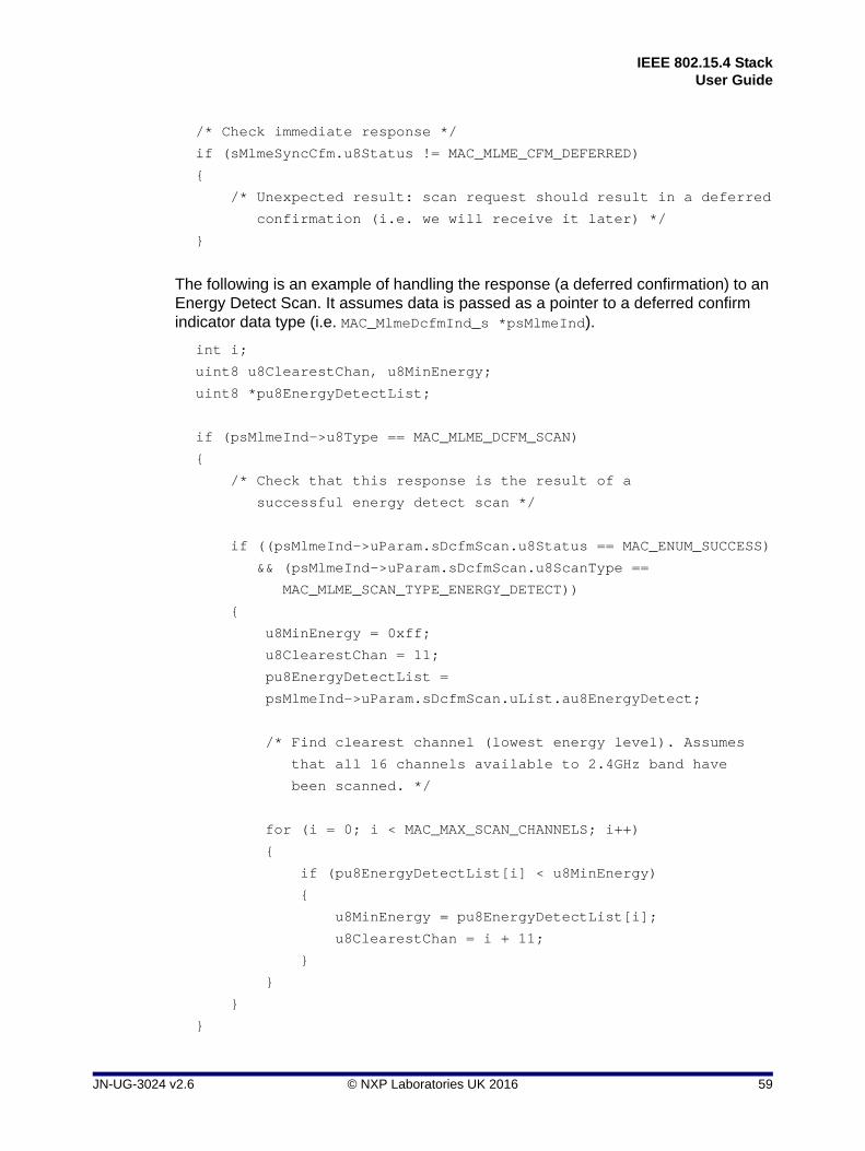
IEEE 802.15.4 StackUser Guide
/* Check immediate response */
if (sMlmeSyncCfm.u8Status != MAC_MLME_CFM_DEFERRED)
{
/* Unexpected result: scan request should result in a deferred
confirmation (i.e. we will receive it later) */
}
The following is an example of handling the response (a deferred confirmation) to an Energy Detect Scan. It assumes data is passed as a pointer to a deferred confirm indicator data type (i.e. MAC_MlmeDcfmInd_s *psMlmeInd).
int i;
uint8 u8ClearestChan, u8MinEnergy;
uint8 *pu8EnergyDetectList;
if (psMlmeInd->u8Type == MAC_MLME_DCFM_SCAN)
{
/* Check that this response is the result of a
successful energy detect scan */
if ((psMlmeInd->uParam.sDcfmScan.u8Status == MAC_ENUM_SUCCESS)
&& (psMlmeInd->uParam.sDcfmScan.u8ScanType ==
MAC_MLME_SCAN_TYPE_ENERGY_DETECT))
{
u8MinEnergy = 0xff;
u8ClearestChan = 11;
pu8EnergyDetectList =
psMlmeInd->uParam.sDcfmScan.uList.au8EnergyDetect;
/* Find clearest channel (lowest energy level). Assumes
that all 16 channels available to 2.4GHz band have
been scanned. */
for (i = 0; i < MAC_MAX_SCAN_CHANNELS; i++)
{
if (pu8EnergyDetectList[i] < u8MinEnergy)
{
u8MinEnergy = pu8EnergyDetectList[i];
u8ClearestChan = i + 11;
}
}
}
}
JN-UG-3024 v2.6 © NXP Laboratories UK 2016 59

Chapter 3Network and Node Operations
3.3 Start
The Start feature is used by an FFD to begin acting as the Co-ordinator of a new PAN or to begin transmitting beacons when associated with a PAN. A PAN should only be started after an Active Scan has been performed in order to find which PAN IDs are currently in use. A PAN is started using the MLME-START.request primitive.
3.3.1 Start Messages
3.3.1.1 Start Request
Beacon generation is requested using the MLME-Start.request primitive. The request is sent using the vAppApiMlmeRequest() function. The request structure MAC_MlmeReqStart_s is detailed in Section 6.1.15.
3.3.1.2 Start Confirm
A MLME-Start.confirm primitive is generated by the MAC to inform the Application/NWK layer of the results of an MLME-Start.request. The confirm message is sent to the Application/NWK layer using the callback routines registered at system start-up in the call to u32AppApiInit(). It may also be sent synchronously to the Application/NWK layer as part of the vAppApiMlmeRequest() call used to send the Start request. The confirm structure MAC_MlmeCfmStart_s is detailed in Section 6.1.29.
3.3.2 Start Example
The following is an example of a typical Start request.
#define DEMO_PAN_ID 0x1234
/* Structures used to hold data for MLME request and response */
MAC_MlmeReqRsp_s sMlmeReqRsp;
MAC_MlmeSyncCfm_s sMlmeSyncCfm;
/* Start beacons */
sMlmeReqRsp.u8Type = MAC_MLME_REQ_START;
sMlmeReqRsp.u8ParamLength = sizeof(MAC_MlmeReqStart_s);
sMlmeReqRsp.uParam.sReqStart.u16PanId = DEMO_PAN_ID;
sMlmeReqRsp.uParam.sReqStart.u8Channel = 11;
/* Eight beacons per second */
sMlmeReqRsp.uParam.sReqStart.u8BeaconOrder = 3;
/* Only receive during first half of superframe: save energy */
sMlmeReqRsp.uParam.sReqStart.u8SuperframeOrder = 2;
60 © NXP Laboratories UK 2016 JN-UG-3024 v2.6

IEEE 802.15.4 StackUser Guide
sMlmeReqRsp.uParam.sReqStart.u8PanCoordinator = TRUE;
sMlmeReqRsp.uParam.sReqStart.u8BatteryLifeExt = FALSE;
sMlmeReqRsp.uParam.sReqStart.u8Realignment = FALSE;
sMlmeReqRsp.uParam.sReqStart.u8SecurityEnable = FALSE;
vAppApiMlmeRequest(&sMlmeReqRsp, &sMlmeSyncCfm);
/* Handle synchronous confirm */
if (sMlmeSyncCfm.u8Status != MAC_MLME_CFM_OK)
{
/* Error during MLME-Start */
}
3.4 Synchronisation
The MAC supports the Synchronisation feature as defined in Sections 7.1.14 and 7.5.4 of the IEEE 802.15.4 Standard (2003).
The purpose of the synchronisation feature is to allow devices to synchronise to beacon transmissions from their Co-ordinators in order to be able to receive pending data held on the Co-ordinator. Where a PAN does not perform beacon transmission, data synchronisation is performed by the device polling its Co-ordinator. A device can only acquire synchronisation to a beacon in the PAN in which it is associated - on receiving a beacon, it can either track the beacon (switching on its receiver at some point before the beacon is due to be transmitted) or receive a single beacon and then not attempt to receive any others.
3.4.1 Initialising Synchronisation
Synchronisation is initiated using the MLME_SYNC.request primitive, which starts a search for a beacon (see Section 3.4.3.1). During the beacon search, the device listens for a beacon for a time 2n +1 ‘base superframes’ (‘base superframe’ duration is 960 symbols), where n is the beacon order contained in the PIB. The search is repeated MAC_MAX_LOST_BEACONS (4) times and if a beacon is not found at the end of this search then the Sync Loss indication is issued (see Section 3.4.3.2).
If a previously synchronised device, which is tracking a beacon, misses MAC_MAX_LOST_BEACONS (4) consecutive beacons, synchronisation has been lost and a Sync Loss indication is issued.
JN-UG-3024 v2.6 © NXP Laboratories UK 2016 61

Chapter 3Network and Node Operations
3.4.2 Conflict Notification
Synchronisation is also lost if a PAN ID conflict is detected due to one of the following situations:
A Co-ordinator receives a beacon with the PAN Co-ordinator indicator set and the same PAN ID that it is using
A Co-ordinator receives a PAN ID conflict notification from a device
A device receives a beacon with the PAN Co-ordinator indicator set and the PAN ID that it expects but from a different Co-ordinator
In the last case, the device transmits a PAN ID conflict notification message to its PAN Co-ordinator.
The Sync Loss indication will be issued (see Section 3.4.3.2).
3.4.3 Sync Messages
3.4.3.1 Sync Request
The MLME-SYNC.request primitive is used to instruct the MAC to attempt to acquire a beacon. The request is sent to the MAC using the vAppApiMlmeRequest() function. The request structure MAC_MlmeReqSync_s is detailed in Section 6.1.16.
3.4.3.2 Sync Loss Indication
The Sync Loss indication is used to inform the Application/NWK layer that there has been a loss of synchronisation with the beacon, either by a previously synchronised device tracking the beacon or because a beacon could not be found during a beacon search initiated by an MLME-SYNC.request. The indication message is sent to the Application/NWK layer using the callback routines registered at system start-up in the call to u32AppApiInit(). The indication structure MAC_MlmeIndSyncLoss_s is detailed in Section 6.1.36.
3.5 Beacons and Polling
If a valid beacon is received by a device (i.e. comes from the correct Co-ordinator address and has the correct PAN ID), a Beacon Notify indication is generated by the MAC to the Application/NWK layer (see Section 3.5.1). Depending on the setting of MAC_PIB_ATTR_AUTO_REQUEST in the PIB, the MAC may start to extract pending data from the Co-ordinator.
If a beacon is received that uses security and an error occurs when it is being processed, the MAC generates an MLME-COMM-STATUS.indication to the Application/NWK layer (see Section 3.2.2.5) with a status of MAC_ENUM_FAILED_SECURITY_CHECK. The indication structure MAC_MlmeIndCommStatus_s is detailed in Section 6.1.37.
62 © NXP Laboratories UK 2016 JN-UG-3024 v2.6

IEEE 802.15.4 StackUser Guide
For non-beaconing PANs, a device can extract pending data from its Co-ordinator by issuing an MLME-POLL.request (see Section 3.5.2.1) and the presence of data will be returned in the corresponding MLME-POLL.confirm (see Section 3.5.2.2), together with the actual data in an MCPS-DATA.indication primitive (see Section 3.8.4).
3.5.1 Beacon Notify Indication
A Beacon Notify indication is generated by the MAC to inform the Application/NWK layer that a beacon transmission has been received. The indication message is sent to the Application/NWK layer using the callback routines registered at system start-up in the call to u32AppApiInit(). The indication structure MAC_MlmeIndBeacon_s is detailed in Section 6.1.35.
3.5.2 Poll Messages
3.5.2.1 Poll Request
The MLME-POLL.request primitive is used to instruct the MAC to attempt to retrieve pending data for the device from a Co-ordinator in a non-beaconing PAN. The request is sent to the MAC using the vAppApiMlmeRequest() function. The request structure MAC_MlmeReqPoll_s is detailed in Section 6.1.17.
3.5.2.2 Poll Confirm
A Poll Confirm is generated by the MAC to inform the Application/NWK layer of the state of a Poll request. The confirm message is sent to the Application/NWK layer using the callback routines registered at system start-up in the call to u32AppApiInit(). It may also be sent synchronously to the Application/NWK layer as part of the vAppApiMlmeRequest() call used to send the Poll request. The confirm structure MAC_MlmeCfmPoll_s is detailed in Section 6.1.25.
If the Poll confirm has status MAC_ENUM_SUCCESS to show that data is available, the data will be indicated to the Application/NWK layer using a MCPS-DATA.indication primitive (see Section 3.8.4).
3.5.3 Beacon Examples
The following is an example of a beacon synchronisation request.
/* Structures used to hold data for MLME request and response */
MAC_MlmeReqRsp_s sMlmeReqRsp;
MAC_MlmeSyncCfm_s sMlmeSyncCfm;
/* Create sync request on channel 11 */
sMlmeReqRsp.u8Type = MAC_MLME_REQ_SYNC;
sMlmeReqRsp.u8ParamLength = sizeof(MAC_MlmeReqSync_s);
JN-UG-3024 v2.6 © NXP Laboratories UK 2016 63

Chapter 3Network and Node Operations
sMlmeReqRsp.uParam.sReqSync.u8Channel = 11;
sMlmeReqRsp.uParam.sReqSync.u8TrackBeacon = TRUE;
/* Post sync request. There is no deferred confirm for this, we just
get a SYNC-LOSS later if it didn't work */ vAppApiMlmeRequest(&sMlmeReqRsp, &sMlmeSyncCfm);
The following is an example of handling a Beacon Notify event (stores the beacon payload). The example assumes that data is passed as a pointer to a deferred confirm indicator data type, i.e. MAC_MlmeDcfmInd_s *psMlmeInd.
uint8 au8Payload[MAC_MAX_BEACON_PAYLOAD_LEN];
int i;
if (psMlmeInd->u8Type == MAC_MLME_IND_BEACON_NOTIFY)
{
for (i = 0; i < psMlmeInd->uParam.sIndBeacon.u8SDUlength; i++))
{
/* Store beacon payload */
au8Payload[i] = psMlmeInd->uParam.sIndBeacon.u8SDU[i];
}
}
3.5.4 Polling Example
The following is an example of using a Poll request to check if the Co-ordinator has any data pending for the device. It is assumed that u16CoordShortAddr has been previously initialised.
#define DEMO_PAN_ID 0x1234
/* Structures used to hold data for MLME request and response */
MAC_MlmeReqRsp_s sMlmeReqRsp;
MAC_MlmeSyncCfm_s sMlmeSyncCfm;
/* Create a poll request */
sMlmeReqRsp.u8Type = MAC_MLME_REQ_POLL;
sMlmeReqRsp.u8ParamLength = sizeof(MAC_MlmeReqPoll_s);
sMlmeReqRsp.uParam.sReqPoll.u8SecurityEnable = FALSE;
sMlmeReqRsp.uParam.sReqPoll.sCoord.u8AddrMode = 2; /* Short address */
sMlmeReqRsp.uParam.sReqPoll.sCoord.u16PanId = DEMO_PAN_ID;
sMlmeReqRsp.uParam.sReqPoll.sCoord.uAddr.u16Short = u16CoordShortAddr;
/* Post poll request, response will be a deferred MLME-Poll.confirm.
64 © NXP Laboratories UK 2016 JN-UG-3024 v2.6

IEEE 802.15.4 StackUser Guide
Will also receive a MCPS-Data.indication event if the coordinator has
sent data. */
vAppApiMlmeRequest(&sMlmeReqRsp, &sMlmeSyncCfm);
3.6 Association
The Association feature allows a device to join a PAN.
Before a device can associate with a PAN, it must first find a PAN. It should perform a MLME-Reset.request (see Section 3.1.1.1) before performing either an Active or Passive Scan using MLME-Scan.request (see Section 3.2.2.1), which will generate a list of the PANs that have been found. The Application/NWK layer can then choose with which PAN it wishes to associate. At this point, an MLME-Associate.request primitive (see Section 3.6.1.1) is issued by the Application/NWK layer, which results in an Association Request command being sent from the device to the Co-ordinator. This command is acknowledged by the Co-ordinator. After a period of time has elapsed, the device MAC sends a Data Request command (see Section 3.8.2) to the Co-ordinator to extract the result of the association. The Co-ordinator acknowledges this command and this is followed by an Association Response command from the Co-ordinator which carries the status of the association attempt. On receiving the association response, the MAC generates an MLME-ASSOCIATE.confirm primitive giving the result of the association request (see Section 3.6.1.2).
At the Co-ordinator, reception of the Association Request command results in the MLME raising an MLME-ASSOCIATE.indication to the Application/NWK layer (see Section 3.6.1.3), which must process the indication and generate an MLME-ASSOCIATE.response primitive to the MAC (see Section 3.6.1.4). On receiving a data request from the device, the above Associate Response command is sent to the device performing the association. The device will acknowledge reception of this command and the status of the MLME-ASSOCIATE.response will be reported to the Co-ordinator by the MLME generating a MLME-COMM-STATUS.indication (see Section 3.6.1.5).
3.6.1 Associate Messages
3.6.1.1 Associate Request
The MLME-ASSOCIATE.request primitive is used by the Application/NWK layer of an unassociated device to instruct the MAC to attempt to request an association with a Co-ordinator. The Associate Request is sent to the MAC using the function MAC_vHandleMlmeReqRsp(). The request structure MAC_MlmeReqAssociate_s is detailed in Section 6.1.7.
JN-UG-3024 v2.6 © NXP Laboratories UK 2016 65

Chapter 3Network and Node Operations
3.6.1.2 Associate Confirm
An Associate Confirm is generated by the MAC to inform the Application/NWK layer of the state of an Association Request. The confirm message is sent to the Application/NWK layer using the callback routines registered at system start-up in the call to MAC_vRegisterMlmeDcfmIndCallbacks(). It may also be sent synchronously to the Application/NWK layer as part of the MAC_vHandleMcpsReqRsp() call to send the Associate Request. The confirm structure MAC_MlmeCfmAssociate_s is detailed in Section 6.1.23.
3.6.1.3 Associate Indication
An Associate Indication is generated by the MAC to inform the Application/NWK layer that an Association Request command has been received. The indication message is sent to the Application/NWK layer using the callback routines registered at system start-up in the call to u32AppApiInit(). The indication structure MAC_MlmeIndAssociate_s is detailed in Section 6.1.32.
3.6.1.4 Associate Response
An Associate Response is generated by the Application/NWK layer in response to receiving an Associate Indication. The response is sent using the function vAppApiMlmeRequest(). The response structure MAC_MlmeRspAssociate_s is detailed in Section 6.1.19.
3.6.1.5 Comm Status Indication
A Comm Status Indication is issued by the MAC to the Application/NWK to report on the status of the Associate Response primitive. The indication structure MAC_MlmeIndCommStatus_s is detailed in Section 6.1.37.
3.6.2 Association Examples
The following is an example of a typical Associate request.
#define DEMO_PAN_ID 0x1234
#define DEMO_COORD_ADDR 0x0e00
/* Structures used to hold data for MLME request and response */
MAC_MlmeReqRsp_s sMlmeReqRsp;
MAC_MlmeSyncCfm_s sMlmeSyncCfm;
/* Create associate request. We know short address and PAN ID of
coordinator as this is preset and we have checked that received
beacon matched this */
sMlmeReqRsp.u8Type = MAC_MLME_REQ_ASSOCIATE;
66 © NXP Laboratories UK 2016 JN-UG-3024 v2.6

IEEE 802.15.4 StackUser Guide
sMlmeReqRsp.u8ParamLength = sizeof(MAC_MlmeReqAssociate_s);
sMlmeReqRsp.uParam.sReqAssociate.u8LogicalChan = 11;
/* We want short address, other features off */
sMlmeReqRsp.uParam.sReqAssociate.u8Capability = 0x80;
sMlmeReqRsp.uParam.sReqAssociate.u8SecurityEnable = FALSE;
sMlmeReqRsp.uParam.sReqAssociate.sCoord.u8AddrMode = 2;
sMlmeReqRsp.uParam.sReqAssociate.sCoord.u16PanId = DEMO_PAN_ID;
sMlmeReqRsp.uParam.sReqAssociate.sCoord.uAddr.u16Short= DEMO_COORD_ADDR;
/* Put in associate request and check immediate confirm. Should be
deferred, in which case response is handled by event handler */
vAppApiMlmeRequest(&sMlmeReqRsp, &sMlmeSyncCfm);
/* Handle synchronous confirm */
if (sMlmeSyncCfm.u8Status != MAC_MLME_CFM_DEFERRED)
{
/* Unexpected result, expecting a deferred confirm */
}
The following is an example of a device handling an Associate Confirm event (it stores the short address assigned to it by the Co-ordinator in the variable u16ShortAddr). It assumes that data is passed as a pointer to a deferred confirm indicator data type,i.e. MAC_MlmeDcfmInd_s *psMlmeInd.
if (psMlmeInd->u8Type == MAC_MLME_DCFM_ASSOCIATE)
{
if (psMlmeInd->uParam.sDcfmAssociate.u8Status == MAC_ENUM_SUCCESS)
{
/* Store short address */
u16ShortAddr = psMlmeInd->
uParam.sDcfmAssociate.u16AssocShortAddr;
}
}
JN-UG-3024 v2.6 © NXP Laboratories UK 2016 67

Chapter 3Network and Node Operations
The following is an example of a Co-ordinator handling an Associate Indication message and the generation of the appropriate response. It assumes that data is passed as a pointer to a deferred confirm indicator data type, i.e. MAC_MlmeDcfmInd_s *psMlmeInd.
/* Structures used to hold data for MLME request and response */
MAC_MlmeReqRsp_s sMlmeReqRsp;
MAC_MlmeSyncCfm_s sMlmeSyncCfm;
tsDemoData sDemoData;
uint16 u16ShortAddress;
uint32 u32AddrLo;
uint32 u32AddrHi;
uint8 u8Node;
uint8 u8AssocStatus;
if (psMlmeInd->u8Type == MAC_MLME_IND_ASSOCIATE)
{
/* Default short address */
u16ShortAddress = 0xffff;
/* Check node extended address matches and device wants short
address */
u32AddrLo = psMlmeInd->
uParam.sIndAssociate.sDeviceAddr.u32L);
u32AddrHi = psMlmeInd->
uParam.sIndAssociate.sDeviceAddr.u32H);
if ((u32AddrHi == DEMO_EXT_ADDR_HI)
&& (u32AddrLo >= DEMO_ENDPOINT_EXT_ADDR_LO_BASE)
&& (u32AddrLo < (DEMO_ENDPOINT_EXT_ADDR_LO_BASE
+ DEMO_ENDPOINTS))
&& (psMlmeInd->uParam.sIndAssociate.u8Capability & 0x80))
{
/* Check if already associated (idiot proofing) */
u8Node = 0;
while (u8Node < sDemoData.sNode.u8AssociatedNodes)
{
if ((u32AddrHi ==
sDemoData.sNode.asAssocNodes[u8Node].u32ExtAddrHi)
&& (u32AddrLo ==
68 © NXP Laboratories UK 2016 JN-UG-3024 v2.6
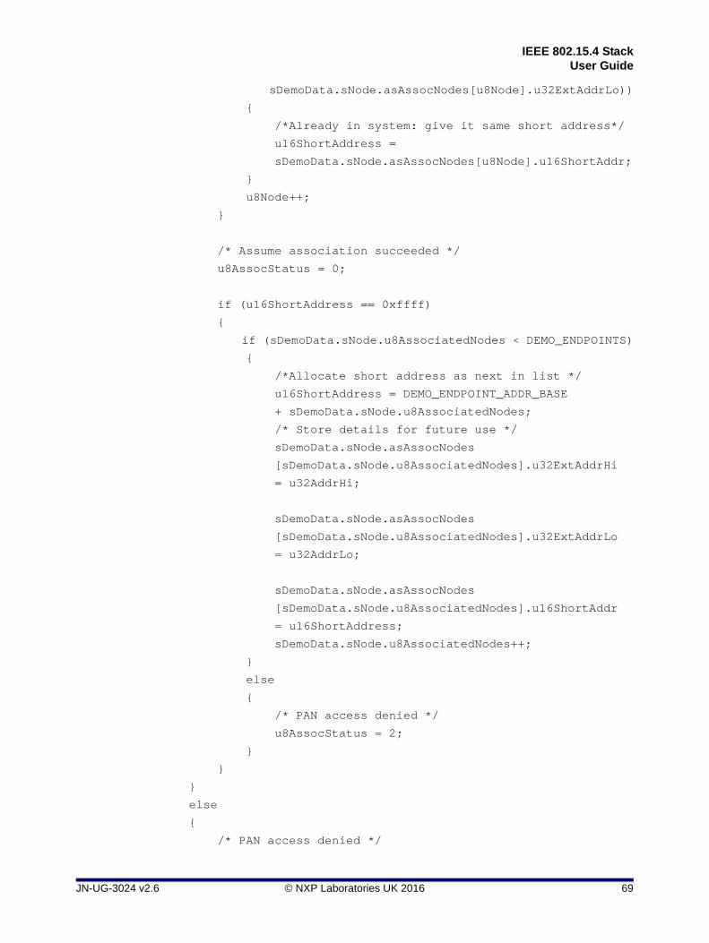
IEEE 802.15.4 StackUser Guide
sDemoData.sNode.asAssocNodes[u8Node].u32ExtAddrLo))
{
/*Already in system: give it same short address*/
u16ShortAddress =
sDemoData.sNode.asAssocNodes[u8Node].u16ShortAddr;
}
u8Node++;
}
/* Assume association succeeded */
u8AssocStatus = 0;
if (u16ShortAddress == 0xffff)
{
if (sDemoData.sNode.u8AssociatedNodes < DEMO_ENDPOINTS)
{
/*Allocate short address as next in list */
u16ShortAddress = DEMO_ENDPOINT_ADDR_BASE
+ sDemoData.sNode.u8AssociatedNodes;
/* Store details for future use */
sDemoData.sNode.asAssocNodes
[sDemoData.sNode.u8AssociatedNodes].u32ExtAddrHi
= u32AddrHi;
sDemoData.sNode.asAssocNodes
[sDemoData.sNode.u8AssociatedNodes].u32ExtAddrLo
= u32AddrLo;
sDemoData.sNode.asAssocNodes
[sDemoData.sNode.u8AssociatedNodes].u16ShortAddr
= u16ShortAddress;
sDemoData.sNode.u8AssociatedNodes++;
}
else
{
/* PAN access denied */
u8AssocStatus = 2;
}
}
}
else
{
/* PAN access denied */
JN-UG-3024 v2.6 © NXP Laboratories UK 2016 69

Chapter 3Network and Node Operations
u8AssocStatus = 2;
}
/* Create association response */
sMlmeReqRsp.u8Type = MAC_MLME_RSP_ASSOCIATE;
sMlmeReqRsp.u8ParamLength = sizeof(MAC_MlmeRspAssociate_s);
memcpy(sMlmeReqRsp.uParam.sRspAssociate.sDeviceAddr,
psMlmeInd->uParam.sIndAssociate.sDeviceAddr,
MAC_EXT_ADDR_LEN);
sMlmeReqRsp.uParam.sRspAssociate.u16AssocShortAddr =
u16ShortAddress;
sMlmeReqRsp.uParam.sRspAssociate.u8Status = u8AssocStatus;
sMlmeReqRsp.uParam.sRspAssociate.u8SecurityEnable = FALSE;
/* Send association response */
vAppApiMlmeRequest(&sMlmeReqRsp, &sMlmeSyncCfm);
/* There is no confirmation for an association response,
hence no need to check */
3.7 Disassociate
The Disassociate feature allows a device which was previously associated with a PAN to terminate its membership of the PAN. To disassociate from a PAN, the device will issue an MLME-DISASSOCIATE.request primitive. This can also be used by a PAN Co-ordinator to cause an associated device to leave the PAN.
The Application/NWK layer issues a Disassociate Request. When this is issued by a device, a Disassociate Notification command is sent to the PAN Co-ordinator. If the request was issued by a Co-ordinator, the notification command is stored for later transmission and the beacon contents are updated to show that there is a message pending for the device to be disassociated.
When a Disassociate Notification message has been transmitted, an acknowledgement is sent in return. On receiving the acknowledgement, the MAC generates an MLME-DISASSOCIATE.confirm to the Application/NWK layer.
If the Disassociate Request was sent by a device, on receiving the Disassociate Notification command the MAC on the Co-ordinator will generate an MLME-DISASSOCIATE.indication to indicate to the Co-ordinator Application/Network layer that a device is leaving the PAN.
70 © NXP Laboratories UK 2016 JN-UG-3024 v2.6

IEEE 802.15.4 StackUser Guide
3.7.1 Disassociate Request
The MLME-DISASSOCIATE.request primitive is used by the Application/NWK layer of an associated device to tell the MAC to disassociate from the Co-ordinator of a PAN. It is also used by the Application/NWK layer of a Co-ordinator to remove an associated device from the PAN. The request is sent to the MAC using the routine vAppApiMlmeRequest(). The request structure MAC_MlmeReqDisassociate_s is detailed in Section 6.1.8.
3.7.2 Disassociate Confirm
A Disassociate Confirm is generated by the MAC to inform the Application/NWK layer of the state of a Disassociate Request. The confirm message is sent to the Application/NWK layer using the callback routines registered at system start-up in the call to u32AppApiInit(). It may also be sent synchronously to the Application/NWK layer as part of the vAppApiMlmeRequest() used to send the Disassociate Request. The Disassociate Confirm structure MAC_MlmeCfmDisassociate_s is detailed in Section 6.1.24.
3.7.3 Disassociate Indication
A Disassociate Indication is generated by the MAC to inform the Application/NWK layer that a Disassociate Notification command has been received. The indication message is sent to the Application/NWK layer using the callback routines registered at system start-up in the call to u32AppApiInit(). The Disassociate Indication structure MAC_MlmeIndDisassociate_s is detailed in Section 6.1.33.
3.7.4 Disassociation Examples
The following is an example of a request to disassociate a device from a PAN
/* Structures used to hold data for MLME request and response */
MAC_MlmeReqRsp_s sMlmeReqRsp;
MAC_MlmeSyncCfm_s sMlmeSyncCfm;
/* Post disassociate request for device to leave PAN */
sMlmeReqRsp.u8Type = MAC_MLME_REQ_DISASSOCIATE;
sMlmeReqRsp.u8ParamLength = sizeof(MAC_MlmeReqDisassociate_s);
sMlmeReqRsp.uParam.sReqDisassociate.sAddr.u8AddrMode = 2; /* Short */
sMlmeReqRsp.uParam.sReqDisassociate.sAddr.uAddr.u16Short =
u16CoordShortAddr;
sMlmeReqRsp.uParam.sReqDisassociate.u8Reason = 2; /* Device leave PAN */
sMlmeReqRsp.uParam.sReqDisassociate.u8SecurityEnable = FALSE;
JN-UG-3024 v2.6 © NXP Laboratories UK 2016 71

Chapter 3Network and Node Operations
vAppApiMlmeRequest(&sMlmeReqRsp, &sMlmeSyncCfm);
/* Handle synchronous confirm */
if (sMlmeSyncCfm.u8Status != MAC_MLME_CFM_DEFERRED)
{
/* Unexpected result, expecting a deferred confirm */
3.8 Data Transmission and Reception
The MAC provides a data service for the transmission and reception of data. Data is transmitted using the MCPS-DATA.request; the status of the transmission is reported by the MCPS-DATA.confirm. Reception of data is indicated to the Application/NWK layer by the MAC raising a MCPS-DATA.indication.
3.8.1 Transmission Power
The radio transmission power of a JN516x/7x device can be varied - for example, a JN5168 standard-power module has a transmission power range of -32 to 0 dBm. To set the transmission power, you can use the function eAppApiPlmeSet() to set the relevant PHY PIB attribute (specified by PHY_PIB_ATTR_TX_POWER). The required function call is:
eAppApiPlmeSet(PHY_PIB_ATTR_TX_POWER, x);
where x is a 6-bit two’s complement power level, yielding a range of -32 to +31. In practice, this value is mapped to an actual transmission level:
For JN5168, JN5164 and JN5161, it is mapped to one of four levels, as indicated in Table 5 below (note that the ‘standard-power’ figures refer to the power levels of the JN516x device itself while the ‘high-power’ figures include the external amplification on the module).
For JN5169 and JN517x, it is mapped to the nearest of 26 levels in the range -32 to +10 dBm.
Therefore, some positive input values will be truncated (to +10 dBm for the JN5169/7x devices and to 0 dBm for the other JN516x devices).
Lower 6 Bits of Parameter x
As Two’s Complement Values
Mapped Power Level (dBm)
Standard-Power Modules High-Power Modules
JN516x JN516x M05 JN516x M06
32 to 39 -32 to -25 -32 -26 -11
40 to 51 -24 to -13 -20 -15 +1
52 to 63 -12 to -1 -9 -3 +13
0 to 31 0 to 31 0 +9.5 +22
Table 5: Power Level Mappings for JN516x Modules (except JN5169)
72 © NXP Laboratories UK 2016 JN-UG-3024 v2.6

IEEE 802.15.4 StackUser Guide
The parameter x can be set as the desired power level (in dBm) cast to a uint32 - for example, to achieve a -9 dBm power setting on a JN5168 standard-power module, the required function call would be:
eAppApiPlmeSet(PHY_PIB_ATTR_TX_POWER, (uint32)(-9));
Notes:
When using a JN516x/7x high-power module, before calling eAppApiPlmeSet() it is necessary to call vAppApiSetHighPowerMode() in order to specify the module type and to enable high-power mode. For further details, refer to the description on page 97.
When using a JN5169 or JN517x module, the function vAppApiSetComplianceLimits() can be called to set the maximum power output to be within the limits for the relevant region of the world. For further details, refer to the description on page 98.
The function vAppApiSetComplianceLimits() can also be used on JN5169/7x modules to set the CCA threshold value which is used to determine whether a channel is busy.
3.8.2 Data Request
The MCPS-DATA.request primitive is used by the Application/NWK layer to transmit a frame of data to a destination device. The request is sent to the MAC using the vAppApiMcpsRequest() routine. The request structure MAC_McpsReqData_s is detailed in Section 6.2.5.
3.8.3 Data Confirm
An MCPS-DATA.confirm primitive is generated by the MAC to inform the Application/NWK layer of the state of an MCPS-DATA.request. The confirm message is sent to the Application/NWK layer using the callback routines registered at system start-up in the call to u32AppApiInit(). It may also be sent synchronously to the Application/NWK layer as part of the vAppApiMcpsRequest() call used to send the Data Request. The Data Confirm structure MAC_McpsCfmData_s is detailed in Section 6.2.7.
3.8.4 Data Indication
An MCPS-DATA.indication is generated by the MAC to inform the Application/NWK layer of the reception of a data packet. The indication message is sent to the Application/NWK layer using the callback routines registered at system start-up in the call to vAppApiMcpsRequest(). The Data Indication structure MAC_McpsIndData_s is detailed in Section 6.2.11.
JN-UG-3024 v2.6 © NXP Laboratories UK 2016 73

Chapter 3Network and Node Operations
3.8.5 Purge Request
The MCPS-PURGE.request primitive is used by the Application/NWK layer to remove a data frame from a transaction queue where it is held prior to transmission. The request is sent to the MAC using the vAppApiMcpsRequest() function. The request structure MAC_McpsReqPurge_s is detailed in Section 6.2.6.
3.8.6 Purge Confirm
An MCPS-PURGE.confirm primitive is generated by the MAC to inform the Application/NWK layer of the result of an MCPS-PURGE.request primitive. The confirm message is sent to the Application/NWK layer using the callback routines registered at system start-up in the call to u32AppApiInit(). It may also be sent synchronously to the Application/NWK layer as part of the vAppApiMcpsRequest() function used to send the Purge Request. The Purge Confirm structure MAC_McpsCfmPurge_s is detailed in Section 6.2.8.
3.8.7 Data Transfer Examples
The following is an example of a device transmitting data to a Co-ordinator using a Data Request. The variable u8CurrentTxHandle is set at a higher layer and is just used as a data frame tag. The variable u16ShortAddr contains the short address of the device that is transmitting the data.
#define DEMO_PAN_ID 0x0e1c
#define DEMO_COORD_ADDR 0x0e00
/* Structures used to hold data for MLME request and response */
MAC_McpsReqRsp_s sMcpsReqRsp;
MAC_McpsSyncCfm_s sMcpsSyncCfm;
uint8 *pu8Payload;
/* Create frame transmission request */
sMcpsReqRsp.u8Type = MAC_MCPS_REQ_DATA;
sMcpsReqRsp.u8ParamLength = sizeof(MAC_McpsReqData_s);
/* Set handle so we can match confirmation to request */
sMcpsReqRsp.uParam.sReqData.u8Handle = u8CurrentTxHandle;
/* Use short address for source */
sMcpsReqRsp.uParam.sReqData.sFrame.sAddr.sSrc.u8AddrMode = 2;
sMcpsReqRsp.uParam.sReqData.sFrame.sAddr.sSrc.u16PanId = DEMO_PAN_ID;
sMcpsReqRsp.uParam.sReqData.sFrame.sAddr.sSrc.uAddr.u16Short =
74 © NXP Laboratories UK 2016 JN-UG-3024 v2.6

IEEE 802.15.4 StackUser Guide
u16ShortAddr;
/* Use short address for destination */
sMcpsReqRsp.uParam.sReqData.sFrame.sAddr.sDst.u8AddrMode = 2;
sMcpsReqRsp.uParam.sReqData.sFrame.sAddr.sDst.u16PanId = DEMO_PAN_ID;
sMcpsReqRsp.uParam.sReqData.sFrame.sAddr.sDst.uAddr.u16Short =
DEMO_COORD_ADDR;
/* Frame requires ack but not security, indirect transmit or GTS */
sMcpsReqRsp.uParam.sReqData.sFrame.u8TxOptions = MAC_TX_OPTION_ACK;
/* Set payload, only use first 8 bytes */
sMcpsReqRsp.uParam.sReqData.sFrame.u8SduLength = 8;
pu8Payload = sMcpsReqRsp.uParam.sReqData.sFrame.au8Sdu;
pu8Payload[0] = 0x00;
pu8Payload[1] = 0x01;
pu8Payload[2] = 0x02;
pu8Payload[3] = 0x03;
pu8Payload[4] = 0x04;
pu8Payload[5] = 0x05;
pu8Payload[6] = 0x06;
pu8Payload[6] = 0x07;
/* Request transmit */
vAppApiMcpsRequest(&sMcpsReqRsp, &sMcpsSyncCfm);
A Data Confirm can be sent to the application via callbacks.
PRIVATE void vProcessIncomingMcps(MAC_McpsDcfmInd_s *psMcpsInd)
{
/* Process MCPS indication by checking if it is a confirmation of
our outgoing frame */
if ((psMcpsInd->u8Type == MAC_MCPS_DCFM_DATA)
&& (sDemoData.sSystem.eState == E_STATE_TX_DATA))
{
if (psMcpsInd->uParam.sDcfmData.u8Handle ==
sDemoData.sTransceiver.u8CurrentTxHandle)
{
/* Increment handle for next time. Increment failures */
sDemoData.sTransceiver.u8CurrentTxHandle++;
JN-UG-3024 v2.6 © NXP Laboratories UK 2016 75

Chapter 3Network and Node Operations
/* Start to read sensors. This takes a while but rather
* than wait for an interrupt we just poll and, once
* finished, move back to the running state to wait for
* the next beacon. Not a power saving solution! */
sDemoData.sSystem.eState = E_STATE_READ_SENSORS;
vProcessRead();
sDemoData.sSystem.eState = E_STATE_RUNNING;
}
}
}
The following is an example of handling the Data Indication event that is generated by the MAC layer of a Co-ordinator when data is received. The variable u16DeviceAddr contains the short address of the device from which we want to receive data. This example assumes that data is passed as a pointer to a deferred confirm indicator data type, i.e. MAC_McpsDcfmInd_s *psMcpsInd.
MAC_RxFrameData_s *psFrame;
MAC_Addr_s *psAddr;
uint16 u16NodeAddr;
au8DeviceData[8];
if (psMcpsInd->u8Type == MAC_MCPS_IND_DATA)
{
psFrame = &psMcpsInd->uParam.sIndData.sFrame;
psAddr = &psFrame->sAddrPair.sSrc;
/* Using short addressing mode */
if (psAddr->u8AddrMode == 2)
{
/* Get address of device that is sending the data */
u16NodeAddr = psAddr->uAddr.u16Short;
/* If this is the device we want */
if (u16NodeAddr == u16DeviceAddr)
{
/* Store the received data, only interested in 8 bytes */
for(i = 0; i < 8; i++)
{
au8DeviceData[i] = psFrame->au8Sdu[i];
}
}
}
}
76 © NXP Laboratories UK 2016 JN-UG-3024 v2.6

IEEE 802.15.4 StackUser Guide
The following is an example of a request to purge a data frame from the transaction queue. The variable u8PurgeItemHandle defines which item is to be purged and is set by a higher layer.
/* Structures used to hold data for MLME request and response */
MAC_McpsReqRsp_s sMcpsReqRsp;
MAC_McpsSyncCfm_s sMcpsSyncCfm;
/* Send request to remove a data frame from transaction queue */
sMcpsReqRsp.u8Type = MAC_MCPS_REQ_PURGE;
sMlmeReqRsp.u8ParamLength = sizeof(MAC_McpsReqPurge_s);
sMlmeReqRsp.uParam.sReqPurge.u8Handle = u8PurgeItemHandle;
/* Request transmit */
vAppApiMcpsRequest(&sMcpsReqRsp, &sMcpsSyncCfm);
The following is an example of handling a Purge Confirm event. This example assumes data is passed as a pointer to a deferred confirm indicator data type, i.e. MAC_McpsDcfmInd_s *psMcpsInd.
if (psMcpsInd->u8Type == MAC_MCPS_DCFM_PURGE)
{
if (psMcpsInd->uParam.sCfmPurge.u8Status != MAC_ENUM_SUCCESS)
{
/* Purge request failed */
}
}
3.8.8 Receive Enable
The Receive Enable feature allows a device to control when its receiver will be enabled or disabled, and for how long. On beacon-enabled PANs, the timings are relative to superframe boundaries; on non-beacon-enabled PANs, the receiver is enabled immediately.
3.8.9 Receive Enable Request
The MLME-RX-ENABLE.request primitive is used by the Application/NWK layer to request that the receiver is enabled at a particular time and for a particular duration. The request is sent to the MAC using the vAppApiMlmeRequest() routine. The request structure MAC_MlmeReqRxEnable_s is detailed in Section 6.1.12.
A new Receive Enable Request must be generated for each attempt to enable the receiver.
JN-UG-3024 v2.6 © NXP Laboratories UK 2016 77

Chapter 3Network and Node Operations
3.8.10 Receive Enable Confirm
An MLME-RX-ENABLE.confirm primitive is generated by the MAC to inform the Application/NWK layer of the result of an MLME-RX-ENABLE.request primitive. The confirm message is sent to the Application/NWK layer using the callback routines registered at system start-up in the call to u32AppApiInit(). It may also be sent synchronously to the Application/NWK layer as part of the vAppApiMlmeRequest() function used to send the Receive Enable Request. The Receive Enable Confirm structure MAC_MlmeCfmRxEnable_s is detailed in Section 6.1.26.
3.8.11 Receive Enable Examples
The following is an example of an Receiver Enable Request.
#define RX_ON_TIME0x00
#define RX_ON_DURATION0x200000
/* Structures used to hold data for MLME request and response */
MAC_MlmeReqRsp_s sMlmeReqRsp;
MAC_MlmeSyncCfm_s sMlmeSyncCfm;
/* Post receiver enable request */
sMlmeReqRsp.u8Type = MAC_MLME_REQ_RX_ENABLE;
sMlmeReqRsp.u8ParamLength = sizeof(MAC_MlmeReqRxEnable_s);
sMlmeReqRsp.uParam.sReqRxEnable.u8DeferPermit = TRUE;
sMlmeReqRsp.uParam.sReqRxEnable.u32RxOnTime = RX_ON_TIME;
sMlmeReqRsp.uParam.sReqRxEnable.u32RxOnDuration = RX_ON_DURATION);
vAppApiMlmeRequest(&sMlmeReqRsp, &sMlmeSyncCfm);
/* Handle response */
if (sMlmeSyncCfm.u8Status != MAC_ENUM_SUCCESS)
{
/* Receiver not enabled */
}
78 © NXP Laboratories UK 2016 JN-UG-3024 v2.6

IEEE 802.15.4 StackUser Guide
3.9 Guaranteed Time Slot (GTS)
Guaranteed Time Slots (GTSs) allow portions of a superframe to be assigned to a device for its exclusive use, to allow communications between the device and the PAN Co-ordinator. Up to 7 GTSs can be allocated, provided that there is enough room in the superframe; a slot may be a multiple superframe slots in length. The PAN Co-ordinator is responsible for allocating and deallocating GTSs. Requests for allocation of GTSs are made by devices. GTSs may be deallocated by the PAN Co-ordinator or by the device which owns the slots. A GTS has a defined direction (transmit or receive relative to the device) and a device may request a transmit GTS and a receive GTS. A device must be tracking beacons in order to be allowed to use GTSs.
The result of an allocation or deallocation of a GTS is transmitted in the beacon; in the case of the allocation, information such as the start slot, slot length and the device short address are transmitted as part of the GTS descriptor. The contents of the beacon are examined to allow the GTS Confirm primitive to report the status of the allocation or deallocation attempt.
3.9.1 GTS Request
The MLME-GTS.request primitive is used by the Application/NWK layer to request that the receiver is enabled at a particular time and for a particular duration. The request is sent to the MAC using the vAppApiMlmeRequest() function. The request structure MAC_MlmeReqGts_s is detailed in Section 6.1.10.
3.9.2 GTS Confirm
An MLME-GTS.confirm primitive is generated by the MAC to inform the Application/NWK layer of the result of an MLME-GTS.request primitive. The confirm message is sent to the Application/NWK layer using the callback routines registered at system start-up in the call to u32AppApiInit(). It may also be sent synchronously to the Application/NWK layer as part of the vAppApiMlmeRequest() function used to send the GTS Request. The GTS Confirm structure MAC_MlmeCfmGts_s is detailed in Section 6.1.22.
3.9.3 GTS Indication
A GTS Indication is generated by the MAC to inform the Application/NWK layer that a GTS Request command to allocate or deallocate a GTS has been received, or on a PAN Co-ordinator where the GTS deallocation is generated by the Co-ordinator itself. The indication message is sent to the Application/NWK layer using the callback routines registered at system start-up in the call to u32AppApiInit(). The GTS Indication structure MAC_MlmeIndGts_s is detailed in Section 6.1.34.
JN-UG-3024 v2.6 © NXP Laboratories UK 2016 79

Chapter 3Network and Node Operations
3.9.4 GTS Examples
The following is an example of a device making a GTS request to the PAN Co-ordinator:
/* Structures used to hold data for MLME request and response */
MAC_MlmeReqRsp_s sMlmeReqRsp;
MAC_MlmeSyncCfm_s sMlmeSyncCfm;
uint8 u8Characteristics = 0;
/* Make GTS request for 4 slots, in tx direction */
sMlmeReqRsp.u8Type = MAC_MLME_REQ_GTS;
sMlmeReqRsp.u8ParamLength = sizeof(MAC_MlmeReqGts_s);
sMlmeReqRsp.uParam.MAC_MlmeReqGts_s.u8SecurityEnable = TRUE;
/* characterstics defined in mac_sap.h */
u8Characteristics |= 4 << MAC_GTS_LENGTH_BIT;
u8Characteristics |= MAC_GTS_DIRECTION_TX << MAC_GTS_DIRECTION_BIT;
u8Characteristics |= MAC_GTS_TYPE_ALLOC << MAC_GTS_TYPE_BIT;
sMlmeReqRsp.uParam.MAC_MlmeReqGts_s.u8Characteristics =
u8Characteristics;
/* Put in associate request and check immediate confirm. Should
be deferred, in which case response is handled by event handler */
vAppApiMlmeRequest(&sMlmeReqRsp, &sMlmeSyncCfm);
/* Handle synchronous confirm */
if (sMlmeSyncCfm.u8Status != MAC_MLME_CFM_DEFERRED)
{
/* Unexpected result - handle error*/
}
The following is an example of handling a deferred GTS confirm (generated by the MAC layer in response to the above request). Assumes data is passed as a pointer to a deferred confirm indicator data type i.e. MAC_MlmeDcfmInd_s *psMlmeInd.
if (psMlmeInd->u8Type == MAC_MLME_DCFM_GTS)
{
if (psMlmeInd->uParam.MAC_MlmeCfmGts_s.u8Status == MAC_ENUM_SUCCESS)
{
/* GTS allocated successfully, store characteristics */
u8Characteristics = psMlmeInd->
uParam.MAC_MlmeCfmGts_s.u8Characteristics;
80 © NXP Laboratories UK 2016 JN-UG-3024 v2.6

IEEE 802.15.4 StackUser Guide
u8GtsLength = (u8Characteristics & MAC_GTS_LENGTH_MASK);
u8GtsDirection = (u8Characteristics & MAC_GTS_DIRECTION_MASK) >>
MAC_GTS_DIRECTION_BIT;
u8GtsType = (u8Characteristics & MAC_GTS_TYPE_MASK) >>
MAC_GTS_TYPE_BIT;
}
}
The following example shows a Co-ordinator handling a GTS Indication event (generated by the MAC layer following the reception of a GTS Request command from a device). This example assumes that data is passed as a pointer to a deferred confirm indicator data type, i.e. MAC_MlmeDcfmInd_s *psMlmeInd.
if (psMlmeInd->u8Type == MAC_MLME_IND_GTS)
{
/* determine whether allocation or de-allocation has occurred */
u8Characteristics = psMlmeInd->
uParam.MAC_MlmeIndGts_s.u8Characteristics;
u8GtsType = (u8Characteristics & MAC_GTS_TYPE_MASK) >>
MAC_GTS_TYPE_BIT;
if (u8GtsType == MAC_GTS_TYPE_DEALLOC)
{
/* handle de-allocation of GTS */
}
else
{
/* handle allocation of GTS */
}
}
JN-UG-3024 v2.6 © NXP Laboratories UK 2016 81

Chapter 3Network and Node Operations
3.10 PIB Access
The PAN Information Base (PIB) consists of a number of parameters or attributes used by the MAC and PHY layers. They describe the Personal Area Network in which the node exists. The detailed use of these parameters is described in the IEEE 802.15.4 Standard and will not be dealt with further here. The MAC and PHY PIB attributes are listed and described in Chapter 8. The mechanisms that a network layer can use to read (set) and write (get) these attributes are described below:
Section 3.10.1 describes access to the MAC PIB attributes
Section 3.10.2 describes access to the PHY PIB attributes
3.10.1 MAC PIB Attributes
The MAC PIB attributes are contained in the structure MAC_Pib_s, defined in the header file mac_pib.h. These attributes are listed and described in Section 8.1. The mechanism for reading (Get) and writing (Set) these attributes depends on the particular attribute. Write accesses to attributes that affect hardware registers must be performed using API functions while all other attribute accesses can be performed directly in the structure.
Setting MAC Attributes via API Functions
Functions are provided in the 802.15.4 Stack API to set MAC PIB attributes that are related to settings in hardware registers. These attributes and their associated ‘Set’ functions are listed in Section 8.1 and the functions are fully detailed in Section 5.3.
Directly Accessing MAC Attributes
All other MAC PIB attributes (other than those that affect hardware registers) can be written directly and all MAC PIB attributes can be read directly.
In order to access the MAC PIB attributes directly, a handle to the PIB is required. The application can obtain a handle to the PIB with the following code:
/* At start of file */
#include "AppApi.h"
#include "mac_pib.h"
PRIVATE void *pvMac;
PRIVATE MAC_Pib_s *psPib;
/* Within application initialization function */
pvMac = pvAppApiGetMacHandle();
psPib = MAC_psPibGetHandle(pvMac);
82 © NXP Laboratories UK 2016 JN-UG-3024 v2.6

IEEE 802.15.4 StackUser Guide
Once the handle is obtained, MAC PIB attributes can be read directly - for example:
bMyAssociationPermit = psPib->bAssociationPermit;
Most of the MAC PIB attributes (other than those that affect hardware registers) can also be written using the PIB handle - for example:
psPib->bAssociationPermit = bMyAssociationPermit;
The following is an example of writing the beacon order attribute in the PIB:
psPib->u8BeaconOrder = 5;
The following is an example of reading the Co-ordinator short address from the PIB:
uint16 u16CoordShortAddr;
u16CoordShortAddr = psPib->u16CoordShortAddr;
The following is an example of writing to one of the variables within an access control list entry:
psPib->asAclEntryDescriptorSet[1].u8AclSecuritySuite = 0x01;
3.10.2 PHY PIB Attributes
The PHY PIB attributes are represented in the 802.15.4 Stack API by enumerations, which are detailed in Section 8.2. Enumerations are also provided for the possible attribute values and are also detailed in Section 8.2. The attributes can be accessed using these enumerations via two API functions, fully described in Section 5.4:
eAppApiPlmeGet() can be used to read (get) a PHY PIB attribute
eAppApiPlmeSet() can be used to write (set) a PHY PIB attribute
3.11 Issuing Service Primitives
The methods for coding the use of service primitives, as introduced in Section 1.15, are outlined in the sub-sections below.
3.11.1 Sending Requests
This section describes how an application sends a Request to the MAC Layer.
Requests can be sent via two possible MAC interfaces:
MLME (MAC Sublayer Management Entity)
MCPS (MAC Common Part Sub-layer)
Both of the above provide an interface to the IEEE 802.15.4 PHY layer. MCPS provides access to the MAC data service.
JN-UG-3024 v2.6 © NXP Laboratories UK 2016 83

Chapter 3Network and Node Operations
A ‘Send’ function is available in the API for each of these two MAC interfaces:
vAppApiMlmeRequest() is used to submit a Request to the MLME interface
vAppApiMcpsRequest() is used to submit a Request to the MCPS interface
These functions are fully described in Section 5.1.
In using these functions, it is necessary to fill in a structure representing the Request to the MAC Layer. Following the function call, the application may receive either a synchronous Confirm, for which space must be allocated, or expect a deferred (asynchronous) Confirm at some later time (the application may elect to perform other tasks while waiting for a deferred Confirm or, if there is nothing to do, go to sleep in order to save power).
Deferred Confirms and Indications are handled by callback functions which are registered by the application as described in Section 3.11.2.
3.11.2 Registering Deferred Confirm/Indication Callbacks
Callback functions must be provided by the application that allow Deferred Confirms and Indications to be passed from the MAC Layer to the MAC User (e.g. application).
These user-defined callback functions must be registered by the application when the API is initialised using the function u32AppApiInit() - callback functions must be provided for each of the MLME and MCPS interfaces:
The parameters prMlmeGetBuffer and prMcpsGetBuffer must point to callback functions that allocate a buffer in which the MAC Layer can store an MLME/MCPS Deferred Confirm or Indication before it is passed to the MAC User.
The parameters prMlmeCallback and prMcpsCallback must point to callback functions that send the buffer containing an MLME/MCPS Deferred Confirm or Indication to the MAC User.
For more information on these parameters and callback functions, refer to the description of u32AppApiInit() in Section 5.2.
This two-phase callback system gives control of buffer allocation to the application. This allows the application to easily implement a basic queuing system for Deferred Confirms and Indications, which are always handled asynchronously.
84 © NXP Laboratories UK 2016 JN-UG-3024 v2.6

IEEE 802.15.4 StackUser Guide
4. Application Development
This chapter provides guidance on IEEE 802.15.4 application coding by detailing the typical set-up and operation of the following node types:
PAN Co-ordinator - see Section 4.2
End Device - see Section 4.3
The described application code is available in application templates (see Section 4.1).
4.1 Application Templates
The application code described in this chapter is provided in the following NXP Application Notes:
IEEE 802.15.4 Application Template for JN516x (JN-AN-1174), which can be downloaded directly from the Wireless Connectivity area of the NXP web site
IEEE 802.15.4 Application Template for JN517x (JN-AN-1211), which is supplied in the JN517x IEEE 802.15.4 SDK (JN-SW-4263), available via the Wireless Connectivity area of the NXP web site
The application templates are fully described in the Application Note documentation and are intended as starting points for your own application development.
The template code is designed such that:
The network topology is a Star network
Short addressing is used
Pre-determined values are used for the PAN ID and short addresses (for the PAN Co-ordinator and End Device(s))
The network is non-beacon enabled (meaning that the PAN Co-ordinator will not transmit regular beacons)
Data transfers are implemented with acknowledgements
There is provision on each device for receiving but not transmitting data (if required, the ability to transmit data must be added during customisation)
No security is implemented
Note: The application for each node type is described in terms of user-defined functions that are defined using the supplied API functions, detailed in Chapter 5.
Note: When developing IEEE 802.15.4 applications, it may also be useful to refer to the example code in the Application Note 802.15.4 Home Sensor Demonstration for JN516x (JN-AN-1180).
JN-UG-3024 v2.6 © NXP Laboratories UK 2016 85

Chapter 4Application Development
4.2 Coding for PAN Co-ordinator
The entry point from the boot loader into the Co-ordinator application is the function AppColdStart() - this is the equivalent of the main() function in other C programs. This function performs the following tasks (also illustrated in Figure 17):
1. AppColdStart() calls the function vInitSystem(), which itself performs the following tasks:
Initialises the IEEE 802.15.4 stack on the device
Sets the PAN ID and short address of the PAN Co-ordinator - in this application, these are pre-determined and are defined in the file config.h
Switches on the radio receiver
Enables the device to accept association requests from other devices
2. AppColdStart() calls the function vStartEnergyScan() which starts an Energy Detection Scan to assess the level of activity in the possible radio frequency channels - the channels to be scanned are defined in the file config.h along with the scan duration. Initiation of the scan is handled as an MLME request to the IEEE 802.15.4 MAC sub-layer.
3. AppColdStart() waits for an MLME response using the function vProcessEventQueues() - this function checks each of the three event queues and processes items found. The function uses the function vProcessIncomingMlme() to handle the MLME response. This function calls vHandleEnergyScanResponse() which processes the results of the Energy Detection Scan - the function searches the results to find the quietest channel and sets this as the adopted channel for the network. The last function then calls vStartCoordinator() which sets the required parameters and then submits an MLME request to start the network (note that no response is expected for this request).
4. AppColdStart() loops the function vProcessEventQueues() to wait for an association request from another device, which arrives as an MLME request (note that the beacon request from the device is handled by the IEEE 802.15.4 stack and is not seen by the application). When the association request arrives, the function vHandleNodeAssociation() is called to process the request. This function creates and submits an association response via MLME.
5. AppColdStart() loops the function vProcessEventQueues() to wait for messages from the associated device arriving via the MCPS and hardware queues.
When data arrives in the MCPS queue, vProcessEventQueues() first uses the function vProcessIncomingMcps() to accept the incoming data frame. Note that vProcessIncomingMcps() uses vHandleMcpsDataInd(), which calls vProcessReceivedDataPacket() in which you must define the processing to be done on the data.
When an event arrives in the hardware queue, vProcessEventQueues() calls the function vProcessIncomingHwEvent() to accept the incoming event. You must define the processing to be performed in this function.
86 © NXP Laboratories UK 2016 JN-UG-3024 v2.6
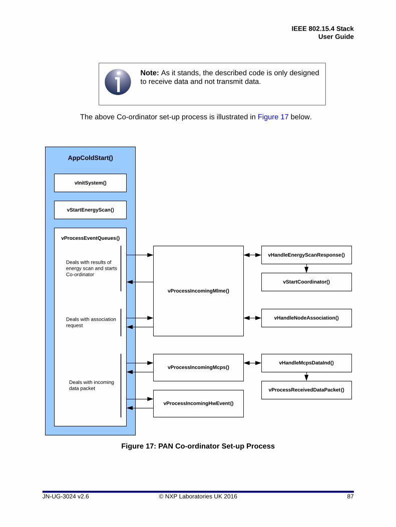
IEEE 802.15.4 StackUser Guide
The above Co-ordinator set-up process is illustrated in Figure 17 below.
Note: As it stands, the described code is only designed to receive data and not transmit data.
Figure 17: PAN Co-ordinator Set-up Process
AppColdStart()
vInitSystem()
vStartEnergyScan()
vProcessEventQueues()
vProcessIncomingMlme()
vHandleEnergyScanResponse()
vStartCoordinator()
vHandleNodeAssociation()
vProcessIncomingMcps()
vProcessIncomingHwEvent()
Deals with results of energy scan and starts Co-ordinator
Deals with association request
Deals with incoming data packet
vHandleMcpsDataInd()
vProcessReceivedDataPacket()
JN-UG-3024 v2.6 © NXP Laboratories UK 2016 87

Chapter 4Application Development
4.3 Coding for End Device
For the End Device, the function AppColdStart() performs the following tasks (also illustrated in Figure 18):
1. AppColdStart() calls the function vInitSystem(), which initialises the IEEE 802.15.4 stack on the device.
2. AppColdStart() calls the function vStartActiveScan() which starts an Active Channel Scan in which the device sends beacon requests to be detected by the PAN Co-ordinator, which then sends out a beacon in response - the channels to be scanned are defined in the file config.h along with the scan duration. Initiation of the scan is handled as an MLME request to the IEEE 802.15.4 MAC sub-layer.
3. AppColdStart() waits for an MLME response using the function vProcessEventQueues() which checks each of the three event queues and processes the items it finds. The function uses the vProcessIncomingMlme() function to handle the MLME response. This function calls the function vHandleActiveScanResponse() which processes the results of the Active Channel Scan:
If a PAN Co-ordinator is found, the function stores the Co-ordinator details (PAN ID, short address, logical channel) and calls vStartAssociate() to submit an association request to the Co-ordinator - this is handled as an MLME request.
If a PAN Co-ordinator is not found (possibly because the Co-ordinator has not yet been initialised), the function recalls vStartActiveScan() in order to restart the scan (in which case this process continues as described from Step 2).
4. AppColdStart() loops the function vProcessEventQueues() to wait for an association response from the Co-ordinator. When the response is received, vProcessIncomingMlme() is called, which (provided that the device is in the associating state) calls the function vHandleAssociateResponse() to process the response. The last functions checks the association response:
If the PAN Co-ordinator has accepted the association, the function puts the device into the 'associated' state.
If the PAN Co-ordinator has rejected the association, the function recalls vStartActiveScan() to start a search for another PAN Co-ordinator (in which case this process continues as described from Step 2).
5. AppColdStart() loops the function vProcessEventQueues() to wait for messages from the PAN Co-ordinator arriving via the MCPS and hardware queues.
When data arrives in the MCPS queue, vProcessEventQueues() first uses the function vProcessIncomingMcps() to accept the incoming data frame. Note that vProcessIncomingMcps() uses vHandleMcpsDataInd(), which calls vProcessReceivedDataPacket() in which you must define the processing to be done on the data.
When an event arrives in the hardware queue, vProcessEventQueues() calls the function vProcessIncomingHwEvent() to accept the incoming event. You must define the processing to be performed in this function.
88 © NXP Laboratories UK 2016 JN-UG-3024 v2.6

IEEE 802.15.4 StackUser Guide
The above End Device set-up process is illustrated in Figure 18 below.
Note: As it stands, the described code is only designed to receive data and not transmit data.
Figure 18: End Device Set-up Process
AppColdStart()
vInitSystem()
vStartActiveScan()
vProcessEventQueues()
vProcessIncomingMlme()
vHandleActiveScanResponse()
vStartAssociate()
vHandleAssociateResponse()
vProcessIncomingMcps()
vProcessIncomingHwEvent()
Deals with results of channel scan and starts association process
Deals with association response
Deals with incoming data packet
vHandleMcpsDataInd()
vProcessReceivedDataPacket()
This diagram shows the program flow assuming that all requests result in successful responses
JN-UG-3024 v2.6 © NXP Laboratories UK 2016 89

Chapter 4Application Development
90 © NXP Laboratories UK 2016 JN-UG-3024 v2.6

IEEE 802.15.4 StackUser Guide
Part II: Reference Information
JN-UG-3024 v2.6 © NXP Laboratories UK 2016 91

92 © NXP Laboratories UK 2016 JN-UG-3024 v2.6

IEEE 802.15.4 StackUser Guide
5. API Functions
This chapter details the C functions of the Application Programming Interface (API) provided in the NXP IEEE 802.15.4 software. The functions are described in the following categories:
Network to MAC Layer functions - see Section 5.1
MAC to Network Layer functions - see Section 5.2
MAC Layer PIB Access functions - see Section 5.3
PHY Layer PIB Access functions - see Section 5.4
The user-defined MLME/MCPS callback functions that must be registered by the Application or NWK layer are detailed in Section 5.5.
The return codes used by some of the API functions are listed and described in Section 5.6.
5.1 Network to MAC Layer Functions
The NWK to MLME and NWK to MCPS interfaces are implemented as functions called from the NWK layer to routines provided by the MAC. The general procedure to use these functions is to fill in a structure representing a request to the MAC and either receive a synchronous confirm, for which space must be allocated, or to expect a deferred (asynchronous) confirm at some time later. The application may elect to perform other tasks while waiting for a deferred confirm or, if there is nothing for it to do, go to sleep to save power.
This section describes the functions used to send the above requests. Functions to select the type of security required and to enable high-power mode (for JN516x/7x high-power modules) are also described.
The functions are listed below, along with their page references:
Function Page
vAppApiMlmeRequest 94
vAppApiMcpsRequest 95
vAppApiSetSecurityMode 96
vAppApiSetHighPowerMode 97
vAppApiSetComplianceLimits 98
JN-UG-3024 v2.6 © NXP Laboratories UK 2016 93
Chapter 5API Functions
vAppApiMlmeRequest
Description
This function is used to pass an MLME request from the NWK layer or Application to the MAC. The request is specified in a MAC_MlmeReqRsp_s structure (detailed in Section 6.1.1). A pointer to a MAC_MlmeSyncCfm_s structure (see Section 6.1.5) must also be provided in which a synchronous confirm will be received. If the confirm is deferred, this will be indicated in the status returned in this structure.
Parameters
*psMlmeReqRsp Pointer to a structure holding the request to the MLME interface (see Section 6.1.1)
*psMlmeSyncCfm Pointer to a structure used to hold the result of a synchronous confirm to a request over the MLME interface (see Section 6.1.5)
Returns
None
void vAppApiMlmeRequest(MAC_MlmeReqRsp_s *psMlmeReqRsp,MAC_MlmeSyncCfm_s *psMlmeSyncCfm);
94 © NXP Laboratories UK 2016 JN-UG-3024 v2.6
IEEE 802.15.4 StackUser Guide
vAppApiMcpsRequest
Description
This function is used to pass an MCPS request from the NWK layer or Application to the MAC. The request is specified in a MAC_McpsReqRsp_s structure (detailed in Section 6.2.1). A pointer to a MAC_McpsSyncCfm_s structure (see Section 6.2.3) must also be provided in which a synchronous confirm will be received. If the confirm is deferred, this will be indicated in the status returned in this structure.
Parameters
*psMcpsReqRsp Pointer to a structure holding the request to the MCPS interface (see Section 6.2.1)
*psMcpsSyncCfm Pointer to a structure used to hold the result of a synchronous confirm to a request over the MCPS interface (see Section 6.2.3)
Returns
None
void vAppApiMcpsRequest(MAC_McpsReqRsp_s *psMcpsReqRsp, MAC_McpsSyncCfm_s *psMcpsSyncCfm);
JN-UG-3024 v2.6 © NXP Laboratories UK 2016 95

Chapter 5API Functions
vAppApiSetSecurityMode
Description
This function is used to select the type of IEEE 802.15.4 MAC-level security to be used - IEEE 802.15.4-2003 or IEEE 802.15.4-2006 security.
If no security is to be implemented, there is no need to call this function.
IEEE 802.15.4 security is introduced in Section 1.16. Useful information on IEEE 802.15.4-2006 security is provided in Appendix B. To implement 802.15.4-2006 security, you should refer to the Application Note 802.15.4 Home Sensor Demonstration for JN516x (JN-AN-1180).
Parameters
eSecurityMode Required security type, one of:
MAC_SECURITY_2003_SOFTWARE (2003 version)MAC_SECURITY_2006 (2006 version)
Returns
None
void vAppApiSetSecurityMode(MAC_SecutityMode_e eSecurityMode);
96 © NXP Laboratories UK 2016 JN-UG-3024 v2.6
IEEE 802.15.4 StackUser Guide
vAppApiSetHighPowerMode
Description
This function is used on a JN516x/7x high-power module to specify the module type (standard-power, M05 high-power or M06 high-power) and enable high-power mode.
For JN5168, the M05 and M06 module types are designed for different world regions:
JN5168-001-M05: This type of module is optimised for use in Europe and Asia. Its power output is within the limit of +10 dBm EIRP dictated by the European Telecommunications Standards Institute (ETSI).
JN5168-001-M06: This type of module is intended for use in North America only.
For the JN5169 and JN517x high-power modules (M06 only), the application must use the function vAppApiSetComplianceLimits() to set the power output levels within the limits imposed in the relevant region of the world. The above function can also be used to set the CCA (Clear Channel Assessment) threshold level.
For JN516x, selecting high-power mode through this function enables the Rx and Tx DIO pins for a high-power module, and also sets the appropriate CCA threshold level for the specified module type. The Rx/Tx DIO pins control the power amplifiers of the RF Rx/Tx paths through a high-power module but can also be used to monitor the receive/transmit behaviour of the JN516x device. Enabling high-power mode for a JN516x standard-power module will not lead to a power increase but will set the CCA threshold to the correct level for this module type and will allow the Rx/Tx DIOs to toggle, which is useful for debug purposes.
For JN517x, this function has no effect on the Rx and Tx DIO pins. These pins must be configured using the function vAHI_RfPinOutputEnable() from the JN517x Integrated Peripherals API and described in the JN517x Integrated Peripherals API User Guide (JN-UG-3118). The above function collectively configures the pins, but they can be configured individually using the vAHI_SetDIOpinMultiplexValue() function, also from the JN517x Integrated Peripherals API.
If required, this function should be called before setting the transmission power using eAppApiPlmeSet() - refer to Section 3.8.1 for more information.
Parameters
u8ModuleID Module type, one of:
APP_API_MODULE_STD (standard-power module)APP_API_MODULE_HPM05 (M05 high-power module)APP_API_MODULE_HPM06 (M06 high-power module)
bMode High-power mode select (always set to TRUE for high-power module):
TRUE - enable high-power modeFALSE - disable high-power mode
Returns
None
void vAppApiSetHighPowerMode(uint8 u8ModuleID, bool_t bMode);
JN-UG-3024 v2.6 © NXP Laboratories UK 2016 97
Chapter 5API Functions
vAppApiSetComplianceLimits
Description
This function can be used on a JN5169 or JN517x device to adapt the MAC layer for high-power modules as well as to satisfy the FCC rules for standard-power JN517x modules.
The function can be used to ensure that the transmit power of a module is within ETSI or FCC limits:
A maximum transmit power for channels 11 to 25 can be configured.
A maximum transmit power for channel 26 can be configured separately, since this channel is close to the top edge of the reserved frequency range and the transmit power on this channel may need to be more strictly limited than on the other channels.
In addition, the CCA (Clear Channel Assessment) threshold value can be configured, which is used to determine whether a channel is busy. This value must be adjusted on high-power modules with a Low-Noise Amplifier (LNA) on the receive path, since the LNA affects the signal strength and therefore the acceptable threshold. For standard-power modules and high-power modules without an LNA on the receive path, the current threshold value should not be changed (specified by a zero setting).
The recommended settings for the JN5169/79 high-power modules are as follows:
If required, this function should be called before the stack and MAC are initialised, in which case the configured limits are applied as soon as the MAC is started. Otherwise, a channel change or transmit power level adjustment is required before the limits take effect - on high-power modules, this can also be achieved by calling vAppApiSetHighPowerMode() after calling this function.
Also, if required, this function should be called before setting the actual transmission power using eAppApiPlmeSet() - refer to Section 3.8.1 for more information.
void vAppApiSetComplianceLimits(int8 i8TxMaxPower, int8 i8TxMaxPowerCh26, uint8 u8CcaThreshold);
Note: On the JN5169 and JN517x devices, flexible high-power module settings have been adopted to allow custom designs to be supported. This requires certain parameter values to be specified directly using this function. On the other JN516x devices, this function is not required because only specific module designs are supported and the required parameter settings are already incorporated in the code.
Module i8TxMaxPower i8TxMaxPowerCh26 u8CcaThreshold
JN5169-001-M06 0 -10 96
JN5179-001-M06 1 -9 90
98 © NXP Laboratories UK 2016 JN-UG-3024 v2.6

IEEE 802.15.4 StackUser Guide
Parameters
i8TxMaxPower Maximum permissible transmit power for channels 11 to 25, in units of dBm. The value 127 indicates that there will be no limit (this is also effectively the case for any value greater than the output level of the module).
i8TxMaxPowerCh26 Maximum permissible transmit power for channel 26, in units of dBm. The value 127 indicates that there will be no limit (this is also effectively the case for any value greater than the output level of the module).
u8CcaThreshold CCA threshold value to be used to determine whether a channel is busy. The value 0 indicates that no change to the current threshold value is required.
Returns
None
JN-UG-3024 v2.6 © NXP Laboratories UK 2016 99

Chapter 5API Functions
5.2 MAC to Network Layer Functions
Communication from the MAC up to the application or network layer is through callback routines implemented by the upper layer and registered with the MAC at system initialisation. In this way, the upper layer can implement the method of dealing with indications and confirmations that suits it best.
This section describes a function used to register the above callback routines, and functions used to save and restore MAC settings.
The functions are listed below, along with their page references:
Function Page
u32AppApiInit 101
vAppApiSaveMacSettings 102
vAppApiRestoreMacSettings 103
100 © NXP Laboratories UK 2016 JN-UG-3024 v2.6

IEEE 802.15.4 StackUser Guide
u32AppApiInit
Description
This function registers four user-defined callback functions provided by the Application/NWK layer, which are used by the MAC and the Integrated Peripherals API to communicate with the Application/NWK layer. Two of the functions are used in MLME communications and two are used in MCPS communications.
The callback functions are as follows:
psMlmeDcfmIndGetBuf(): Called by the MAC to provide a buffer in which to place the result of a deferred MLME callback or indication to send to the Application/NWK layer
vMlmeDcfmIndPost(): Called by the MAC to post (send) the buffer provided by the registered psMlmeDcfmIndGetBuf() function to the Application/NWK layer
psMcpsDcfmIndGetBuf(): Called by the MAC to provide a buffer in which to place the result of a deferred MCPS callback or indication to send to the Application/NWK layer
vMcpsDcfmIndPost(): Called by the MAC to post (send) the buffer provided by the registered psMcpsDcfmIndGetBuf() function to the Application/NWK layer
The above functions are fully detailed in Section 5.5.
Parameters
prMlmeGetBuffer Pointer to psMlmeDcfmIndGetBuf() callback function
prMlmeCallback Pointer to vMlmeDcfmIndPost() callback function
pvMlmeParam Untyped pointer which is passed when calling the registered MLME callback functions
prMcpsGetBuffe Pointer to psMcpsDcfmIndGetBuf() callback function
prMcpsCallback Pointer to vMcpsDcfmIndPost() callback function
pvMcpsParam Untyped pointer which is passed when calling the registered MCPS callback functions
Returns
0 if initialisation failed, otherwise a 32-bit version number (most significant 16 bits are main revision, least significant 16 bits are minor revision)
uint32 u32AppApiInit(PR_GET_BUFFER prMlmeGetBuffer, PR_POST_CALLBACK prMlmeCallback, void *pvMlmeParam, PR_GET_BUFFER prMcpsGetBuffer, PR_POST_CALLBACK prMcpsCallback, void *pvMcpsParam);
JN-UG-3024 v2.6 © NXP Laboratories UK 2016 101

Chapter 5API Functions
vAppApiSaveMacSettings
Description
This function is used to instruct the MAC to save settings in RAM before entering sleep mode with memory held.
Parameters
None
Returns
None
void vAppApiSaveMacSettings(void);
102 © NXP Laboratories UK 2016 JN-UG-3024 v2.6

IEEE 802.15.4 StackUser Guide
vAppApiRestoreMacSettings
Description
This function is used when the device wakes from sleep to restore the MAC to the state that it was in before the device entered sleep mode.
Currently, this feature is only suitable for use in networks that do not use regular beacons, as it does not include a facility to resynchronise.
Parameters
None
Returns
None
void vAppApiRestoreMacSettings(void);
JN-UG-3024 v2.6 © NXP Laboratories UK 2016 103

Chapter 5API Functions
5.3 MAC Layer PIB Access Functions
Certain MAC PIB attributes can only be written to using the functions described in this section. These are attributes that affect hardware register settings and they must not be written to directly (see Section 3.10.1). The attributes are as follows (names are as used in the IEEE 802.15.4 Standard):
macMaxCSMABackoffs
macMinBE
macPANId
macPromiscuousMode
macRxOnWhenIdle
macShortAddress
Each of the above attributes has its own ‘Set’ function for writing its value.
The functions are listed below, along with their page references:
Function Page
MAC_vPibSetMaxCsmaBackoffs 105
MAC_vPibSetMinBe 106
MAC_vPibSetPanId 107
MAC_vPibSetPromiscuousMode 108
MAC_vPibSetRxOnWhenIdle 109
MAC_vPibSetShortAddr 110
104 © NXP Laboratories UK 2016 JN-UG-3024 v2.6

IEEE 802.15.4 StackUser Guide
MAC_vPibSetMaxCsmaBackoffs
Description
This function can be used to set the value of the MAC PIB attribute macMaxCSMABackoffs, which determines the maximum permitted number of CSMA back-offs.
Parameters
*pvMac Pointer to MAC handle
u8MaxCsmaBackoffs Maximum number of CSMA back-offs to set
Returns
None
void MAC_vPibSetMaxCsmaBackoffs(void *pvMac, uint8 u8MaxCsmaBackoffs);
JN-UG-3024 v2.6 © NXP Laboratories UK 2016 105

Chapter 5API Functions
MAC_vPibSetMinBe
Description
This function can be used to set the value of the MAC PIB attribute macMinBE, which determines the minimum permitted value of the CSMA Back-off Exponent (BE).
Parameters
*pvMac Pointer to MAC handle
u8MinBe Minimum BE value to set
Returns
None
void MAC_vPibSetMinBe(void *pvMac, uint8 u8MinBe);
106 © NXP Laboratories UK 2016 JN-UG-3024 v2.6

IEEE 802.15.4 StackUser Guide
MAC_vPibSetPanId
Description
This function can be used to set the value of the MAC PIB attribute macPANId, which holds the 16-bit PAN ID of the network to which the local node belongs.
Parameters
*pvMac Pointer to MAC handle
u16PanId PAN ID to set
Returns
None
void MAC_vPibSetPanId(void *pvMac, uint16 u16PanId);
JN-UG-3024 v2.6 © NXP Laboratories UK 2016 107
Chapter 5API Functions
MAC_vPibSetPromiscuousMode
Description
This function can be used to set the value of the MAC PIB attribute macPromiscuousMode, which enables/disables ‘promiscuous mode’.
Parameters
*pvMac Pointer to MAC handle
bNewState Mode to set:TRUE - promiscuous modeFALSE - non-promiscuous mode
bInReset Indicates whether the function is called following a reset:TRUE - called after reset FALSE - otherwise (default)
Returns
None
void MAC_vPibSetPromiscuousMode(void *pvMac, bool_t bNewState, bool_t bInReset);
108 © NXP Laboratories UK 2016 JN-UG-3024 v2.6

IEEE 802.15.4 StackUser Guide
MAC_vPibSetRxOnWhenIdle
Description
This function can be used to set the value of the MAC PIB attribute macRxOnWhenIdle, which enables/disables the mode ‘receiver on when idle’.
Parameters
*pvMac Pointer to MAC handle
bNewState Mode to set:TRUE - receiver on when idleFALSE - receiver off when idle
bInReset Indicates whether the function is called following a reset:TRUE - called after reset FALSE - otherwise (default)
Returns
None
void MAC_vPibSetRxOnWhenIdle(void *pvMac, bool_t bNewState, bool_t bInReset);
JN-UG-3024 v2.6 © NXP Laboratories UK 2016 109

Chapter 5API Functions
MAC_vPibSetShortAddr
Description
This function can be used to set the value of the MAC PIB attribute macShortAddress, which holds the 16-bit short address of the local node.
Parameters
*pvMac Pointer to MAC handle
u16ShortAddr Short address to set
Returns
None
void MAC_vPibSetShortAddr(void *pvMac, uint16 u16ShortAddr);
110 © NXP Laboratories UK 2016 JN-UG-3024 v2.6

IEEE 802.15.4 StackUser Guide
5.4 PHY Layer PIB Access Functions
The PHY PIB attributes can be accessed using the functions described in this section. The attributes are as follows (names are as used in the IEEE 802.15.4 Standard):
phyCurrentChannel
phyChannelsSupported
phyTransmitPower
phyCCAMode
Each of the above attributes is referenced by an enumeration and its value is set using an enumeration (see Section 8.2).
The functions are listed below, along with their page references:
Function Page
eAppApiPlmeGet 112
eAppApiPlmeSet 113
JN-UG-3024 v2.6 © NXP Laboratories UK 2016 111

Chapter 5API Functions
eAppApiPlmeGet
Description
This function can be used to retrieve the current value of one of the PHY PIB attributes. If the routine returns PHY_ENUM_SUCCESS, the value of the specified PIB PHY attribute retrieved has been copied into the location pointed to by pu32PhyPibValue.
The following example illustrates how to read the current channel:
uint32 u32sChannel;
if (eAppApiPlmeGet (PHY_PIB_ATTR_CURRENT_CHANNEL,&u32sChannel)
== PHY_ENUM_SUCCESS)
{
printf("Channel is %d\n", u32Channel);
}
Parameters
ePhyPibAttribute Enumeration defining which PHY PIB attribute to access (see Section 8.2), one of:
PHY_PIB_ATTR_CURRENT_CHANNELPHY_PIB_ATTR_CHANNELS_SUPPORTEDPHY_PIB_ATTR_TX_POWERPHY_PIB_ATTR_CCA_MODE
*pu32PhyPibValue Pointer to a location used to hold the result of the Get operation
Returns
Enumerated value that indicates success or failure of the operation (see Section 5.6)
PHY_Enum_e eAppApiPlmeGet (PHY_PibAttr_e ePhyPibAttribute, uint32 *pu32PhyPibValue);
112 © NXP Laboratories UK 2016 JN-UG-3024 v2.6

IEEE 802.15.4 StackUser Guide
eAppApiPlmeSet
Description
This function can be used to change the value of one of the PHY PIB attributes. If the routine returns PHY_ENUM_SUCCESS, the value of the specified PHY PIB attribute has been changed to u32PhyPibValue.
The following example illustrates how to set the current channel:
if (eAppApiPlmeSet(PHY_PIB_ATTR_CURRENT_CHANNEL, u8Channel) !=
PHY_ENUM_SUCCESS)
{
// Handle error;
}
This example illustrates how to set the transmit power to 0 dBm:
if (eAppApiPlmeSet(PHY_PIB_ATTR_TX_POWER, 0) != PHY_ENUM_SUCCESS)
{
// Handle error;
}
Parameters
ePhyPibAttribute Enumeration defining which PHY PIB attribute to access (see Section 8.2), one of:
PHY_PIB_ATTR_CURRENT_CHANNELPHY_PIB_ATTR_CHANNELS_SUPPORTEDPHY_PIB_ATTR_TX_POWERPHY_PIB_ATTR_CCA_MODE
u32PhyPibValue The value the PHY PIB attribute will be set to
Returns
Enumerated value that indicates success or failure of the operation (see Section 5.6)
PHY_Enum_e eAppApiPlmeSet(PHY_PibAttr ePhyPibAttribute,uint32 u32PhyPibValue);
Note: Using this function to set the JN516x transmission power level is described in more detail in Section 3.8.1.
JN-UG-3024 v2.6 © NXP Laboratories UK 2016 113

Chapter 5API Functions
5.5 Callback Functions
The initialisation function u32AppApiInit(), described in Section 5.2, registers four user-defined callback functions which are used by the MAC and the Integrated Peripherals API to communicate with the Application or NWK layer. This section details these callback functions.
The functions are listed below, along with their page references:
Function Page
psMlmeDcfmIndGetBuf 115
vMlmeDcfmIndPost 116
psMcpsDcfmIndGetBuf 118
vMcpsDcfmIndPost 119
114 © NXP Laboratories UK 2016 JN-UG-3024 v2.6

IEEE 802.15.4 StackUser Guide
psMlmeDcfmIndGetBuf
Description
This callback function implements MLME buffer management and returns a pointer to a buffer in the form of a MAC_DcfmIndHdr_s structure. This buffer can be used by the MAC to send the results of deferred (asynchronous) confirms as the result of a previous MLME request. The function will also be called by the MAC to provide space to send information to the Application/NWK layer in the form of MLME indications triggered by hardware events.
At its simplest, the buffer could be used to return the address of a variable of the type MAC_MlmeDcfmInd_s known by the Application/NWK layer - for example:
PRIVATE MAC_MlmeDcfmInd_s sMlmeBuffer;
PRIVATE MAC_DcfmIndHdr_s
*psMlmeDcfmIndGetBuf(void *pvParam)
{
/* Return a handle to a MLME buffer */
return (MAC_DcfmIndHdr_s *)&sMlmeBuffer;
}
However, this implementation would be very limited in the number of responses or indications that could be handled at any time. Other suitable implementations within the Application/NWK layer might be a queue, where the next free space is returned, or a pool of buffers which are allocated and freed by the network layer.
In all cases, it is the responsibility of the Application/NWK layer to manage the freeing of buffers carrying deferred confirms and indications. If the network layer cannot provide a buffer, it should return NULL and the confirm/indication will be lost.
The pvParam parameter is a pointer which can be used to specify further information to be carried between the MAC and Application/NWK layer (in either direction) when performing an MLME Get or Post, and contains the pvMlmeParam parameter of u32AppApiInit(). This data can be used for any purpose by the Application/NWK layer and has no meaning to the MAC.
Parameters
pvParam Pointer to information to be passed (in either direction)
Returns
Pointer to MAC_DcfmIndHdr_s buffer (see Section 6.3.8)
MAC_DcfmIndHdr_s *psMlmeDcfmIndGetBuf(void *pvParam);
JN-UG-3024 v2.6 © NXP Laboratories UK 2016 115
Chapter 5API Functions
vMlmeDcfmIndPost
Description
This callback function is used to send the buffer provided by the callback function psMlmeDcfmIndGetBuf() to the Application/NWK layer after the results of the MLME confirm or indication have been filled in.
The function expects to always successfully send the buffer, which is not unreasonable since the Application/NWK layer is responsible for allocating the buffer in the first place. If the implementation is done in such a way that this might not be the case, the Send routine will have no way of signalling that it could not send the buffer up to the Application/NWK layer. It is the responsibility of the Application/NWK layer to provide sufficient buffers to be allocated to avoid losing confirms or indications.
The pvParam parameter is a pointer which can be used to specify further information to be carried between the MAC and Application/NWK layer (in either direction) when performing an MLME Get or Post, and contains the pvMlmeParam parameter of u32AppApiInit(). This data can be used for any purpose by the Application/NWK layer and has no meaning to the MAC.
The psDcfmIndHdr parameter is a pointer to the buffer allocated in the psMlmeDcfmIndGetBuf() call, carrying the information from the confirm/indication from the MAC to the Application/NWK layer.
As an example of what a Post routine might do, consider the following:
PRIVATE void
vMlmeDcfmIndPost(void *pvParam,
MAC_DcfmIndHdr_s *psDcfmIndHdr)
{
/* Place incoming buffer on network layer input queue */
vAddToQueue(psDcfmIndHdr);
/* Signal the network layer that there is at least one
* buffer to process. If using a RTOS, this could be
* a signal to the network layer to begin running to
* process the buffer. In a simple application a
* variable might be polled as here
*/
boNotEmpty = TRUE;
}
In the example, the interface between the MAC and Application/NWK layer is a queue with enough entries to contain all the buffer pointers from a buffer pool managed by the Application/NWK layer for the MLME confirm/indications. The Post routine places the buffer pointer on the queue and then signals to the Application/NWK layer that there is something there to process. This is all happening in the MAC thread of execution, which for a simple system will be in the interrupt context. At
void vMlmeDcfmIndPost(void *pvParam, MAC_DcfmIndHdr_s *psDcfmIndHdr);
116 © NXP Laboratories UK 2016 JN-UG-3024 v2.6

IEEE 802.15.4 StackUser Guide
some stage, the MAC thread will stop running and the Application/NWK layer thread will continue; in this case, it regularly polls the input queue and processes any entries it finds, before returning the buffer back to the buffer pool.
Parameters
pvParam Pointer to information to be passed (in either direction)
psDcfmIndHdr Pointer to the MAC_DcfmIndHdr_s buffer
Returns
None
JN-UG-3024 v2.6 © NXP Laboratories UK 2016 117
Chapter 5API Functions
psMcpsDcfmIndGetBuf
Description
This callback function implements MCPS buffer management and returns a pointer to a buffer in the form of a MAC_DcfmIndHdr_s structure. This buffer can be used by the MAC to send the results of deferred (asynchronous) confirms as the result of a previous MCPS request. The function will also be called by the MAC to provide space to send information to the Application/NWK layer in the form of MCPS indications triggered by hardware events.
At its simplest, the buffer could be used to return the address of a variable of the type MAC_McpsDcfmInd_s known by the Application/NWK layer - for example:
PRIVATE MAC_McpsDcfmInd_s sMcpsBuffer;
PRIVATE MAC_DcfmIndHdr_s
*psMcpsDcfmIndGetBuf(void *pvParam)
{
/* Return a handle to a MCPS buffer */
return (MAC_DcfmIndHdr_s *)&sMcpsBuffer;
}
However, this implementation would be very limited in the number of responses or indications that could be handled at any time. Other suitable implementations within the Application/NWK layer might be a queue, where the next free space is returned, or a pool of buffers which are allocated and freed by the network layer.
In all cases, it is the responsibility of the Application/NWK layer to manage the freeing of buffers carrying deferred confirms and indications. If the network layer cannot provide a buffer, it should return NULL and the confirm/indication will be lost.
The pvParam parameter is a pointer which can be used to specify further information to be carried between the MAC and Application/NWK layer (in either direction) when performing an MCPS Get or Post, and contains the pvMcpsParam parameter of u32AppApiInit(). This data can be used for any purpose by the Application/NWK layer and has no meaning to the MAC.
Parameters
pvParam Pointer to information to be passed (in either direction)
Returns
Pointer to MAC_DcfmIndHdr_s buffer (see Section 6.3.8)
MAC_DcfmIndHdr_s *psMcpsDcfmIndGetBuf(void *pvParam);
118 © NXP Laboratories UK 2016 JN-UG-3024 v2.6

IEEE 802.15.4 StackUser Guide
vMcpsDcfmIndPost
Description
This callback function is used to send the buffer provided by the callback function psMcpsDcfmIndGetBuf() to the Application/NWK layer after the results of the MCPS confirm or indication have been filled in.
The function expects to always successfully send the buffer, which is not unreasonable since the Application/NWK layer is responsible for allocating the buffer in the first place. If the implementation is done in such a way that this might not be the case, the Send routine will have no way of signalling that it could not send the buffer up to the Application/NWK layer. It is the responsibility of the Application/NWK layer to provide sufficient buffers to be allocated to avoid losing confirms or indications.
The pvParam parameter is a pointer which can be used to specify further information to be carried between the MAC and Application/NWK layer (in either direction) when performing an MCPS Get or Post, and contains the pvMcpsParam parameter of u32AppApiInit(). This data can be used for any purpose by the Application/NWK layer and has no meaning to the MAC.
The psDcfmIndHdr parameter is a pointer to the buffer allocated in the psMcpsDcfmIndGetBuf() call, carrying the information from the confirm/indication from the MAC to the Application/NWK layer.
As an example of what a Post routine might do, consider the following:
PRIVATE void
vMcpsDcfmIndPost(void *pvParam,
MAC_DcfmIndHdr_s *psDcfmIndHdr)
{
/* Place incoming buffer on network layer input queue */
vAddToQueue(psDcfmIndHdr);
/* Signal the network layer that there is at least one
* buffer to process. If using a RTOS, this could be
* a signal to the network layer to begin running to
* process the buffer. In a simple application a
* variable might be polled as here
*/
boNotEmpty = TRUE;
}
In the example, the interface between the MAC and Application/NWK layer is a queue with enough entries to contain all the buffer pointers from a buffer pool managed by the Application/NWK layer for the MCPS confirm/indications. The Post routine places the buffer pointer on the queue and then signals to the Application/NWK layer that there is something there to process. This is all happening in the MAC thread of execution, which for a simple system will be in the interrupt context. At
void vMcpsDcfmIndPost(void *pvParam, MAC_DcfmIndHdr_s *psDcfmIndHdr);
JN-UG-3024 v2.6 © NXP Laboratories UK 2016 119

Chapter 5API Functions
some stage, the MAC thread will stop running and the Application/NWK layer thread will continue; in this case, it regularly polls the input queue and processes any entries it finds, before returning the buffer back to the buffer pool.
Parameters
pvParam Pointer to information to be passed (in either direction)
psDcfmIndHdr Pointer to the MAC_DcfmIndHdr_s buffer
Returns
None
120 © NXP Laboratories UK 2016 JN-UG-3024 v2.6
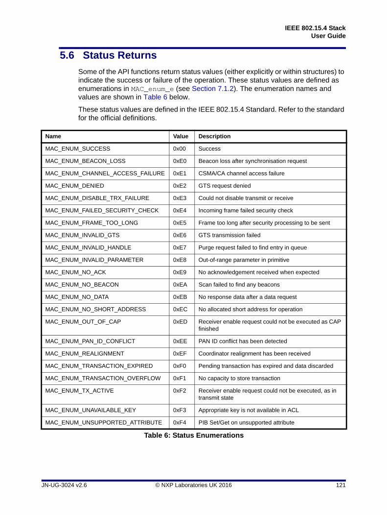
IEEE 802.15.4 StackUser Guide
5.6 Status Returns
Some of the API functions return status values (either explicitly or within structures) to indicate the success or failure of the operation. These status values are defined as enumerations in MAC_enum_e (see Section 7.1.2). The enumeration names and values are shown in Table 6 below.
These status values are defined in the IEEE 802.15.4 Standard. Refer to the standard for the official definitions.
Name Value Description
MAC_ENUM_SUCCESS 0x00 Success
MAC_ENUM_BEACON_LOSS 0xE0 Beacon loss after synchronisation request
MAC_ENUM_CHANNEL_ACCESS_FAILURE 0xE1 CSMA/CA channel access failure
MAC_ENUM_DENIED 0xE2 GTS request denied
MAC_ENUM_DISABLE_TRX_FAILURE 0xE3 Could not disable transmit or receive
MAC_ENUM_FAILED_SECURITY_CHECK 0xE4 Incoming frame failed security check
MAC_ENUM_FRAME_TOO_LONG 0xE5 Frame too long after security processing to be sent
MAC_ENUM_INVALID_GTS 0xE6 GTS transmission failed
MAC_ENUM_INVALID_HANDLE 0xE7 Purge request failed to find entry in queue
MAC_ENUM_INVALID_PARAMETER 0xE8 Out-of-range parameter in primitive
MAC_ENUM_NO_ACK 0xE9 No acknowledgement received when expected
MAC_ENUM_NO_BEACON 0xEA Scan failed to find any beacons
MAC_ENUM_NO_DATA 0xEB No response data after a data request
MAC_ENUM_NO_SHORT_ADDRESS 0xEC No allocated short address for operation
MAC_ENUM_OUT_OF_CAP 0xED Receiver enable request could not be executed as CAP finished
MAC_ENUM_PAN_ID_CONFLICT 0xEE PAN ID conflict has been detected
MAC_ENUM_REALIGNMENT 0xEF Coordinator realignment has been received
MAC_ENUM_TRANSACTION_EXPIRED 0xF0 Pending transaction has expired and data discarded
MAC_ENUM_TRANSACTION_OVERFLOW 0xF1 No capacity to store transaction
MAC_ENUM_TX_ACTIVE 0xF2 Receiver enable request could not be executed, as in transmit state
MAC_ENUM_UNAVAILABLE_KEY 0xF3 Appropriate key is not available in ACL
MAC_ENUM_UNSUPPORTED_ATTRIBUTE 0xF4 PIB Set/Get on unsupported attribute
Table 6: Status Enumerations
JN-UG-3024 v2.6 © NXP Laboratories UK 2016 121

Chapter 5API Functions
122 © NXP Laboratories UK 2016 JN-UG-3024 v2.6

IEEE 802.15.4 StackUser Guide
6. Structures
This chapter describes the structures provided in the header files. The structures are presented in the following categories:
MLME structures - see Section 6.1
MCPS structures - see Section 6.2
Other structures - see Section 6.3
6.1 MLME Structures
6.1.1 MAC_MlmeReqRsp_s
This structure contains an MLME request or response.
typedef struct
{
uint8 u8Type;
uint8 u8ParamLength;
uint16 u16Pad;
MAC_MlmeReqRspParam_u uParam;
} MAC_MlmeReqRsp_s;
where:
u8Type is the request/response type, represented by an enumeration from MAC_MlmeReqRspType_e (see Section 7.3.1).
u8ParamLength is the parameter length, in bits, in the union below.
u16Pad is the number of bits of padding required to make up 32 bits.
uParam is the union of all possible MLME requests/responses (see Section 6.1.2).
JN-UG-3024 v2.6 © NXP Laboratories UK 2016 123

Chapter 6Structures
6.1.2 MAC_MlmeReqRspParam_u
This structure is the union of all possible MLME requests and responses, and is an element of the MAC_MlmeReqRsp_s structure (see Section 6.1.1).
union
{
/* MLME Requests */
MAC_MlmeReqAssociate_s sReqAssociate;
MAC_MlmeReqDisassociate_s sReqDisassociate;
MAC_MlmeReqGet_s sReqGet;
MAC_MlmeReqGts_s sReqGts;
MAC_MlmeReqReset_s sReqReset;
MAC_MlmeReqRxEnable_s sReqRxEnable;
MAC_MlmeReqScan_s sReqScan;
MAC_MlmeReqSet_s sReqSet;
MAC_MlmeReqStart_s sReqStart;
MAC_MlmeReqSync_s sReqSync;
MAC_MlmeReqPoll_s sReqPoll;
/* MLME Responses */
MAC_MlmeRspAssociate_s sRspAssociate;
MAC_MlmeRspOrphan_s sRspOrphan;
/* Vendor Specific Requests */
MAC_MlmeReqVsExtAddr_s sReqVsExtAddr;
} MAC_MlmeReqRspParam_u;
where:
sReqAssociate is a structure that contains an Associate request. For more information on this structure, see Section 6.1.7.
sReqDisassociate is a structure that contains a Disassociate request. For more information on this structure, see Section 6.1.8.
sReqGet is a structure that contains a Get request. For more information on this structure, see Section 6.1.9.
sReqGts is a structure that contains a GTS request. For more information on this structure, see Section 6.1.10.
sReqReset is a structure that contains a Reset request. For more information on this structure, see Section 6.1.11.
sReqRxEnable is a structure that contains a Rx Enable request. For more information on this structure, see Section 6.1.12.
sReqScan is a structure that contains a Scan request. For more information on this structure, see Section 6.1.13.
124 © NXP Laboratories UK 2016 JN-UG-3024 v2.6

IEEE 802.15.4 StackUser Guide
sReqSet is a structure that contains a Set request. For more information on this structure, see Section 6.1.14.
sReqStart is a structure that contains a Start request. For more information on this structure, see Section 6.1.15.
sReqSync is a structure that contains a Sync request. For more information on this structure, see Section 6.1.16.
sReqPoll is a structure that contains a Poll request. For more information on this structure, see Section 6.1.17.
sRspAssociate is a structure that contains an Associate response. For more information on this structure, see Section 6.1.19.
sRspOrphan is a structure that contains an Orphan response. For more information on this structure, see Section 6.1.20.
sReqVsExtAddr is a structure that contains a Vendor-specific Extended Address request. For more information on this structure, see Section 6.1.18.
6.1.3 MAC_MlmeDcfmInd_s
This structure contains an MLME deferred confirm or indication and is passed to the registered deferred confirm/indication callback specified in u32AppApiInit().
typedef struct
{
uint8 u8Type;
uint8 u8ParamLength;
uint16 u16Pad;
MAC_MlmeDcfmIndParam_u uParam;
} MAC_MlmeDcfmInd_s;
where:
u8Type is the deferred confirm/indication type, represented by an enumeration from MAC_MlmeDcfmIndType_e (see Section 7.3.3).
u8ParamLength is the parameter length in the union below.
u16Pad is padding to force alignment.
uParam is the union of all possible MLME deferred confirms/indications (see Section 6.1.4).
JN-UG-3024 v2.6 © NXP Laboratories UK 2016 125

Chapter 6Structures
6.1.4 MAC_MlmeDcfmIndParam_u
This structure is the union of all possible deferred MLME confirms and indications, and is an element of the MAC_MlmeDcfmInd_s structure (see Section 6.1.21).
typedef union
{
MAC_MlmeCfmScan_s sDcfmScan;
MAC_MlmeCfmGts_s sDcfmGts;
MAC_MlmeCfmAssociate_s sDcfmAssociate;
MAC_MlmeCfmDisassociate_s sDcfmDisassociate;
MAC_MlmeCfmPoll_s sDcfmPoll;
MAC_MlmeCfmRxEnable_s sDcfmRxEnable;
MAC_MlmeIndAssociate_s sIndAssociate;
MAC_MlmeIndDisassociate_s sIndDisassociate;
MAC_MlmeIndGts_s sIndGts;
MAC_MlmeIndBeacon_s sIndBeacon;
MAC_MlmeIndSyncLoss_s sIndSyncLoss;
MAC_MlmeIndCommStatus_s sIndCommStatus;
MAC_MlmeIndOrphan_s sIndOrphan;
} MAC_MlmeDcfmIndParam_u;
where:
sDcfmScan is a structure that contains a Scan confirm message, giving the results from an MLME scan request. For more information on this structure, see Section 6.1.21.
sDcfmGts is a structure that contains a GTS confirm message, generated by the MAC to inform the Application/NWK layer of the result of an MLME-GTS.request primitive. For more information on this structure, see Section 6.1.22.
sDcfmAssociate is a structure that contains an Associate confirm message, which is generated by the MAC to inform the Application/NWK layer of the state of an Association request. For more information on this structure, see Section 6.1.23.
sDcfmDisassociate is a structure that contains a Disassociate confirm message, which is generated by the MAC to inform the Application/NWK layer of the state of a Disassociate request. For more information on this structure, see Section 6.1.24.
sDcfmPoll is a structure that contains a Poll confirm message, which is generated by the MAC to inform the Application/NWK layer of the state of a Poll request. For more information on this structure, see Section 6.1.25.
sDcfmRxEnable is a structure that contains the results of a Rx Enable confirm message, which is generated by the MAC to inform the Application/NWK layer of the result of an MLME-RX-ENABLE.request primitive. For more information on this structure, see Section 6.1.26.
sIndAssociate is a structure that contains an Associate indication message, which is generated by the MAC to inform the Application/NWK layer that an
126 © NXP Laboratories UK 2016 JN-UG-3024 v2.6

IEEE 802.15.4 StackUser Guide
Association request command has been received. For more information on this structure, see Section 6.1.32.
sIndDisassociate is a structure that contains a Disassociate indication message, which is generated by the MAC to inform the Application/NWK layer that a Disassociate request command has been received. For more information on this structure, see Section 6.1.33.
sIndGts is a structure that contains the results of a GTS indication message, which is generated by the MAC to inform the Application/NWK layer that a GTS request command to allocate or deallocate a GTS has been received, or on a PAN Co-ordinator where the GTS deallocation is generated by the Co-ordinator itself. For more information on this structure, see Section 6.1.34.
sIndBeacon is a structure that contains a Beacon Notify indication message, which is generated by the MAC to inform the Application/NWK layer that a beacon transmission has been received. For more information on this structure, see Section 6.1.35.
sIndSyncLoss is a structure that contains a Sync Loss indication message, which is used to inform the Application/NWK layer that there has been a loss of synchronisation with the beacon. For more information on this structure, see Section 6.1.36.
sIndCommStatus is a structure that contains a Comm Status indication message, which is generated by the MAC to inform the Application/NWK layer of a Co-ordinator the result of a communication with another node triggered by a previous primitive (MLME-Orphan.response and MLME-Associate.response). For more information on this structure, see Section 6.1.37.
sIndOrphan is a structure that contains an Orphan indication request, which is generated by the MAC of a Co-ordinator to its Application/NWK layer to indicate that it has received an orphan notification message transmitted by an orphan node. For more information on this structure, see Section 6.1.38.
JN-UG-3024 v2.6 © NXP Laboratories UK 2016 127

Chapter 6Structures
6.1.5 MAC_MlmeSyncCfm_s
This structure contains an MLME synchronous confirm.
typedef struct
{
uint8 u8Status;
uint8 u8ParamLength;
uint16 u16Pad;
MAC_MlmeSyncCfmParam_u uParam;
} MAC_MlmeSyncCfm_s;
where:
u8Status is the status of the request which corresponds to the synchronous confirm (for enumerations, see Section 7.3.3).
u8ParamLength is the parameter length in the union below.
u16Pad is padding to force alignment.
uParam is the union of all possible MLME synchronous confirms (see Section 6.1.6).
6.1.6 MAC_MlmeSyncCfmParam_u
This structure is the union of all possible MLME synchronous confirms and is an element of the MAC_MlmeSyncCfm_s structure (see Section 6.1.5).
typedef union
{
MAC_MlmeCfmAssociate_s sCfmAssociate;
MAC_MlmeCfmDisassociate_s sCfmDisassociate;
MAC_MlmeCfmGet_s sCfmGet;
MAC_MlmeCfmGts_s sCfmGts;
MAC_MlmeCfmScan_s sCfmScan;
MAC_MlmeCfmSet_s sCfmSet;
MAC_MlmeCfmStart_s sCfmStart;
MAC_MlmeCfmPoll_s sCfmPoll;
MAC_MlmeCfmReset_s sCfmReset;
MAC_MlmeCfmRxEnable_s sCfmRxEnable;
#ifdef MLME_VS_REG_RW
MAC_MlmeCfmVsRdReg_s sCfmVsRdReg;
#endif /* MLME_VS_REG_RW */
#ifdef TOF_ENABLED
MAC_MlmeCfmTofPoll_s sCfmTofPoll;
MAC_MlmeCfmTofPrime_s sCfmTofPrime;
MAC_MlmeCfmTofDataPoll_s sCfmTofDataPoll;
MAC_MlmeCfmTofData_s sCfmTofData;
128 © NXP Laboratories UK 2016 JN-UG-3024 v2.6

IEEE 802.15.4 StackUser Guide
#endif
} MAC_MlmeSyncCfmParam_u;
where:
sCfmAssociate is a structure that contains an Associate confirm message, which is generated by the MAC to inform the Application/NWK layer of the state of an Association request. For more information on this structure, see Section 6.1.7.
sCfmDisassociate is a structure that contains a Disassociate confirm message, which is generated by the MAC to inform the Application/NWK layer of the state of a Disassociate request. For more information on this structure, see Section 6.1.8.
sCfmGet is a structure that contains a Get confirm message, generated by the MAC to inform the Application/NWK layer of the result of a Get request. For more information on this structure, see Section 6.1.9.
sCfmGts is a structure that contains a GTS confirm message, generated by the MAC to inform the Application/NWK layer of the result of an MLME-GTS.request primitive. For more information on this structure, see Section 6.1.34.
sCfmScan is a structure that contains a Scan confirm message, giving the results from an MLME scan request. For more information on this structure, see Section 6.1.13.
sCfmSet is a structure that contains a Set confirm message, generated by the MAC to inform the Application/NWK layer of the result of a Set request. For more information on this structure, see Section 6.1.28.
sCfmStart is a structure that contains a Start confirm message, generated by the MAC to inform the Application/NWK layer of the result of a Start request. For more information on this structure, see Section 6.1.29.
sCfmPoll is a structure that contains a Poll confirm message, which is generated by the MAC to inform the Application/NWK layer of the state of a Poll request. For more information on this structure, see Section 6.1.17.
sCfmReset is a structure that contains a Reset confirm message, generated by the MAC to inform the Application/NWK layer of the result of a Reset request. For more information on this structure, see Section 6.1.30.
sCfmRxEnable is a structure that contains the results of a Rx Enable confirm message, which is generated by the MAC to inform the Application/NWK layer of the result of an MLME-RX-ENABLE.request primitive. For more information on this structure, see Section 6.1.26.
sCfmVsRdReg is a structure that contains a Vendor-Specific Read Register confirm message which results from a command to read a specific register. For more information on this structure, see Section 6.1.31.
sCfmTofPoll is a structure that contains a Poll confirm for ‘Time of Flight’ (which is not documented here).
sCfmTofPrime is a structure that contains a Prime confirm for ‘Time of Flight’ (which is not documented here).
sCfmTofDataPoll is a structure that contains a Data Poll confirm for ‘Time of Flight’ (which is not documented here).
sCfmTofData is a structure that contains a Data confirm for ‘Time of Flight’ (which is not documented here).
JN-UG-3024 v2.6 © NXP Laboratories UK 2016 129
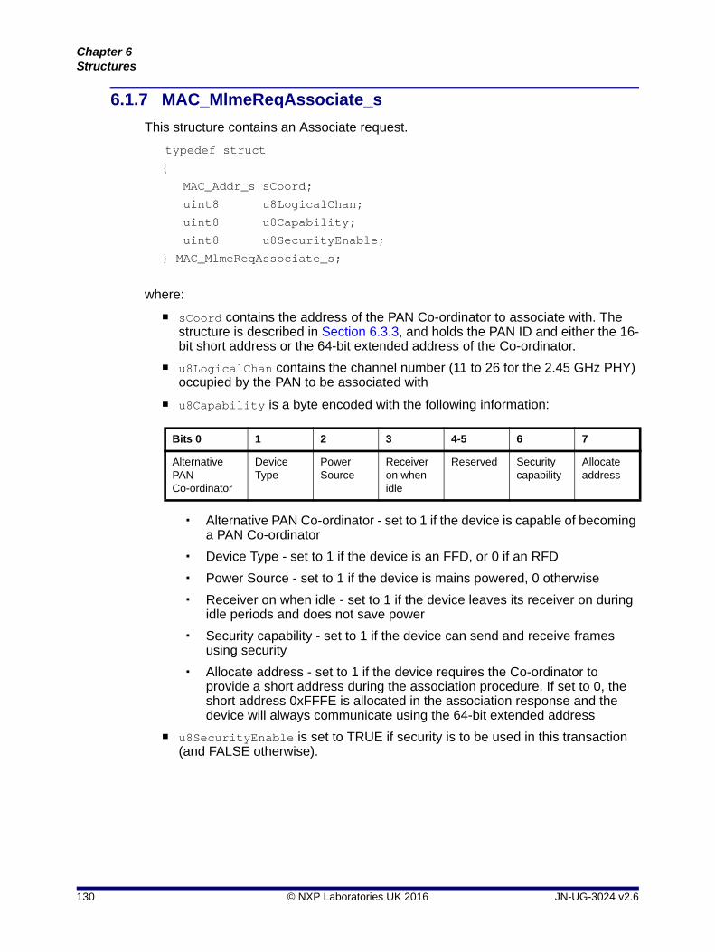
Chapter 6Structures
6.1.7 MAC_MlmeReqAssociate_s
This structure contains an Associate request.
typedef struct {
MAC_Addr_s sCoord;
uint8 u8LogicalChan;
uint8 u8Capability;
uint8 u8SecurityEnable;
} MAC_MlmeReqAssociate_s;
where:
sCoord contains the address of the PAN Co-ordinator to associate with. The structure is described in Section 6.3.3, and holds the PAN ID and either the 16-bit short address or the 64-bit extended address of the Co-ordinator.
u8LogicalChan contains the channel number (11 to 26 for the 2.45 GHz PHY) occupied by the PAN to be associated with
u8Capability is a byte encoded with the following information:
Alternative PAN Co-ordinator - set to 1 if the device is capable of becoming a PAN Co-ordinator
Device Type - set to 1 if the device is an FFD, or 0 if an RFD
Power Source - set to 1 if the device is mains powered, 0 otherwise
Receiver on when idle - set to 1 if the device leaves its receiver on during idle periods and does not save power
Security capability - set to 1 if the device can send and receive frames using security
Allocate address - set to 1 if the device requires the Co-ordinator to provide a short address during the association procedure. If set to 0, the short address 0xFFFE is allocated in the association response and the device will always communicate using the 64-bit extended address
u8SecurityEnable is set to TRUE if security is to be used in this transaction (and FALSE otherwise).
Bits 0 1 2 3 4-5 6 7
Alternative PAN Co-ordinator
Device Type
Power Source
Receiver on when idle
Reserved Security capability
Allocate address
130 © NXP Laboratories UK 2016 JN-UG-3024 v2.6

IEEE 802.15.4 StackUser Guide
6.1.8 MAC_MlmeReqDisassociate_s
This structure contains a Disassociate request.
typedef struct
{
MAC_Addr_s sAddr;
uint8 u8Reason;
uint8 u8SecurityEnable;
} MAC_MlmeReqDisassociate_s;
where:
sAddr contains the address of the recipient of the disassociation request - device or Co-ordinator address (format described in Section 6.3.3)
u8Reason indicates the reason for the Disassociation request - one of:
u8SecurityEnable is set to TRUE if security is to be used in this transaction (and FALSE otherwise).
Disassociation reason Description
0 Reserved
1 Coordinator wishes device to leave the PAN
2 Device wishes to leave the PAN
0x03 - 0x7F Reserved
0x80 - 0xFF Reserved for MAC primitive enumeration values
JN-UG-3024 v2.6 © NXP Laboratories UK 2016 131

Chapter 6Structures
6.1.9 MAC_MlmeReqGet_s
This structure contains a Get request to obtain the value of a MAC PIB attribute.
typedef struct
{
uint8 u8PibAttribute;
uint8 u8PibAttributeIndex;
} MAC_MlmeReqGet_s;
where:
u8PibAttribute is the identifier of the MAC PIB attribute to access, specified using one of the enumerations listed in Section 7.1.1.
u8PibAttributeIndex is the index of the ACL entry to set (not a part of IEEE 802.15.4)
6.1.10 MAC_MlmeReqGts_s
This structure contains a GTS request.
typedef struct
{
uint8 u8Characteristics;
uint8 u8SecurityEnable;
} MAC_MlmeReqGts_s;
where:
u8Characteristics contains the characteristics of the GTS being requested, encoded in a byte as shown below:
* GTS direction is defined relative to the device.
u8SecurityEnable specifies whether security is to be used during the request (TRUE if security to be used, FALSE otherwise).
Bitss 0-3 Bit 4 Bit 5 Bits 6-7
GTS length (in superframe slots)
GTS direction * (0 = Transmit,1 = Receive)
Characteristics type (1 = GTS allocation,0 = GTS deallocation)
Reserved
132 © NXP Laboratories UK 2016 JN-UG-3024 v2.6

IEEE 802.15.4 StackUser Guide
6.1.11 MAC_MlmeReqReset_s
This structure contains a Reset request.
typedef struct
{
uint8 u8SetDefaultPib;
} MAC_MlmeReqReset_s;
where u8SetDefaultPib controls whether the PIB contents are to be reset to their default values (TRUE to reset PIB contents, FALSE otherwise)
6.1.12 MAC_MlmeReqRxEnable_s
This structure contains a Rx Enable request.
struct tagMAC_MlmeReqRxEnable_s
{
uint32 u32RxOnTime;
uint32 u32RxOnDuration;
uint8 u8DeferPermit;
} MAC_MlmeReqRxEnable_s;
where:
u32RxOnTime is a 32-bit quantity specifying the number of symbols after the start of the superframe before the receiver should be enabled
u32RxOnDuration is a 32-bit quantity specifying the number of symbols for which the receiver should remain enabled. If equal to 0, the receiver is disabled.
u8DeferPermit determines whether the ‘enable period’ will be allowed to start in the next full superframe period if the requested ‘on time’ has already passed in the current superframe (TRUE if allowed, FALSE if disallowed).
6.1.13 MAC_MlmeReqScan_s
This structure contains a Scan request.
typedef struct
{
uint32 u32ScanChannels;
uint8 u8ScanType;
uint8 u8ScanDuration;
} MAC_MlmeReqScan_s;
where:
JN-UG-3024 v2.6 © NXP Laboratories UK 2016 133

Chapter 6Structures
u32ScanChannels is a bitmap of the channels that can be scanned - each channel is presented by a bit, which is set to 1 if the channel is to be scanned. Only channels 11-26 are available with the 2.45 GHz PHY, corresponding to bits 11-26. Bits 0-10 and 27-31 are reserved.
u8ScanType indicates the type of scan to be requested, specified using one of the following enumerations:
MAC_MLME_SCAN_TYPE_ENERGY_DETECT
MAC_MLME_SCAN_TYPE_ACTIVE
MAC_MLME_SCAN_TYPE_PASSIVE
MAC_MLME_SCAN_TYPE_ORPHAN
U8ScanDuration is a value in the range 0-14 which determines the time to scan a channel, measured in superframe periods (1 superframe period = 960 symbols). The number of superframe periods in the scan duration is calculated as: 2 x u8ScanDuration + 1.
6.1.14 MAC_MlmeReqSet_s
This structure contains a Set request to set the value of a MAC PIB attribute.
typedef struct
{
uint8 u8PibAttribute;
uint8 u8PibAttributeIndex;
uint16 u16Pad;
MAC_Pib_u uPibAttributeValue;
} MAC_MlmeReqSet_s;
where:
u8PibAttribute is the identifier of the MAC PIB attribute to access, specified using one of the enumerations listed in Section 7.1.1.
u8PibAttributeIndex is the index of the ACL entry to set (not part of IEEE 802.15.4)
u16Pad is the padding for alignment
uPibAttributeValue is the value to be set
134 © NXP Laboratories UK 2016 JN-UG-3024 v2.6

IEEE 802.15.4 StackUser Guide
6.1.15 MAC_MlmeReqStart_s
This structure contains a Start request to start transmitting beacons.
typedef struct
{
uint16 u16PanId;
uint8 u8Channel;
uint8 u8BeaconOrder;
uint8 u8SuperframeOrder;
uint8 u8PanCoordinator;
uint8 u8BatteryLifeExt;
uint8 u8Realignment;
uint8 u8SecurityEnable;
} MAC_MlmeReqStart_s;
where:
u16PanId contains the 16-bit PAN identifier as selected by the Application/NWK layer.
u8Channel specifies the logical channel number (11 to 26 for 2.45 GHz PHY) on which the beacon will be transmitted.
u8BeaconOrder defines how often a beacon will be transmitted. It can take the values 0-15, where 0-14 are used to define the beacon interval, which is calculated as 2**BO multiplied by the base superframe duration (number of symbols in superframe slot x number of slots in superframe = 960 symbols). If the value is 15, beacons are not transmitted and the ‘Superframe Order’ parameter is ignored.
u8SuperframeOrder defines how long the active period of the superframe is including the beacon period. Its value can be from 0 to BeaconOrder, as specified above, or 15. The active period time is specified as 2**SO times the base superframe duration. If the value is 15, the superframe will not be active after the beacon.
u8PanCoordinator is set to TRUE if the FFD is to become the PAN Co-ordinator for a new PAN. Otherwise, if set to FALSE, the FFD will transmit beacons on the existing PAN with which it is associated.
u8BatteryLifeExt can be set to TRUE to allow battery life extension to be used by turning off the receiver of the FFD for a part of the contention period after the beacon is transmitted. If set to FALSE, the receiver remains enabled for the whole of the contention access period after the beacon.
u8Realignment can be set to TRUE to cause a Co-ordinator realignment command to be broadcast prior to changing the superframe settings in order to alert the nodes in the PAN of the change. Set to FALSE otherwise.
u8SecurityEnable is set to TRUE if security is used on beacon frames, or FALSE otherwise.
JN-UG-3024 v2.6 © NXP Laboratories UK 2016 135

Chapter 6Structures
6.1.16 MAC_MlmeReqSync_s
This structure contains a Sync request to instruct the MAC to attempt to acquire a beacon.
typedef struct
{
uint8 u8Channel;
uint8 u8TrackBeacon;
} MAC_MlmeReqSync_s;
where:
u8Channel specifies the logical channel that the MAC will use to try to find beacon transmissions. For the 2.45 GHz PHY, this field can take values in the range 11 to 26.
u8TrackBeacon is set to TRUE if the device is to continue tracking beacon transmissions following reception of the first beacon. Set to FALSE otherwise.
6.1.17 MAC_MlmeReqPoll_s
This structure contains a Poll request to instruct the MAC to attempt to retrieve pending data for the device from a Co-ordinator in a non-beaconing PAN.
struct tagMAC_MlmeReqPoll_s
{
MAC_Addr_s sCoord;
uint8 u8SecurityEnable;
} MAC_MlmeReqPoll_s;
where:
sCoord contains the address of the Co-ordinator to poll for data. The data structure (described in Section 6.3.3) holds the PAN ID and either the 16-bit short address or 64-bit extended address of the Co-ordinator.
u8SecurityEnable can be set to TRUE to enable security processing to be applied to the data request frame which is sent to the Co-ordinator. In this case, the Co-ordinator address is used to look up the security information from the ACL in the PIB. Set to FALSE otherwise.
136 © NXP Laboratories UK 2016 JN-UG-3024 v2.6

IEEE 802.15.4 StackUser Guide
6.1.18 MAC_MlmeReqVsExtAddr_s
This structure contains a Vendor-specific Extended Address request.
typedef struct
{
MAC_ExtAddr_s sExtAddr;
} MAC_MlmeReqVsExtAddr_s;
where sExtAddr is the 64-bit vendor-specific extended address to set (see Section 6.3.5).
6.1.19 MAC_MlmeRspAssociate_s
This structure contains an Associate response.
struct tagMAC_MlmeRspAssociate_s
{
MAC_ExtAddr_s sDeviceAddr;
uint16 u16AssocShortAddr;
uint8 u8Status;
uint8 u8SecurityEnable;
} MAC_MlmeRspAssociate_s;
where:
sDeviceAddr contains the associating device's 64-bit extended address
u16AssocShortAddr contains the 16-bit short address allocated to the associating device by the PAN Co-ordinator. If the association was unsuccessful, the short address will be set to 0xFFFF
6.1.20 MAC_MlmeRspOrphan_s
This structure contains an Orphan response.
typedef struct
{
MAC_ExtAddr_s sOrphanAddr;
uint8 u16OrphanShortAddr;
uint8 u8Associated;
uint8 u8SecurityEnable;
} MAC_MlmeRspOrphan_s;
where:
sOrphanAddr contains the full 64-bit extended address of the orphan node, as carried in the Orphan Indication.
JN-UG-3024 v2.6 © NXP Laboratories UK 2016 137
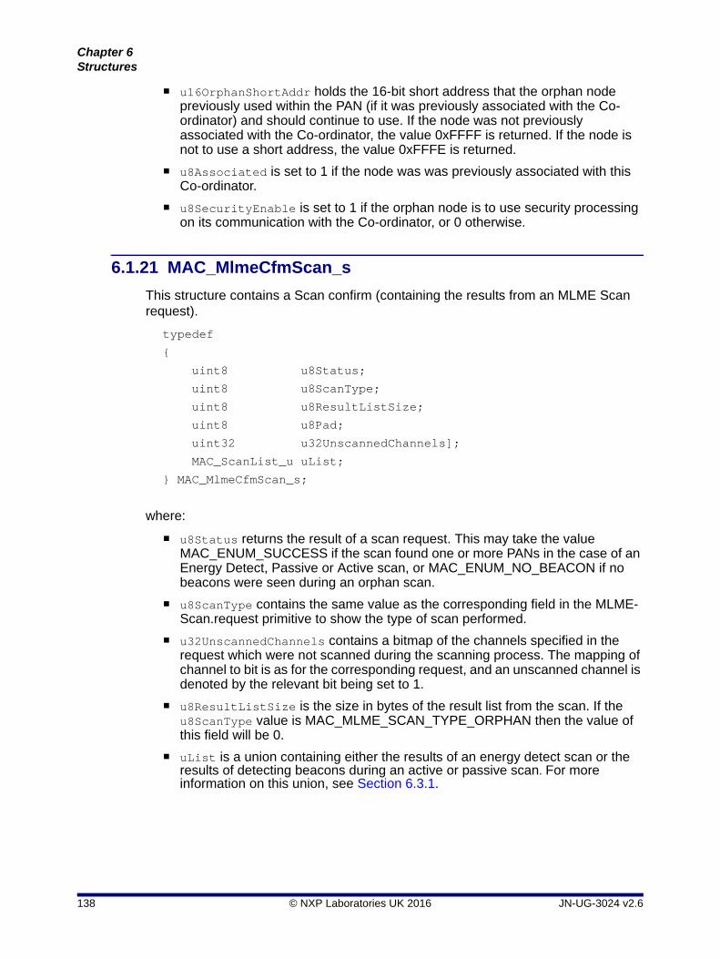
Chapter 6Structures
u16OrphanShortAddr holds the 16-bit short address that the orphan node previously used within the PAN (if it was previously associated with the Co-ordinator) and should continue to use. If the node was not previously associated with the Co-ordinator, the value 0xFFFF is returned. If the node is not to use a short address, the value 0xFFFE is returned.
u8Associated is set to 1 if the node was was previously associated with this Co-ordinator.
u8SecurityEnable is set to 1 if the orphan node is to use security processing on its communication with the Co-ordinator, or 0 otherwise.
6.1.21 MAC_MlmeCfmScan_s
This structure contains a Scan confirm (containing the results from an MLME Scan request).
typedef
{
uint8 u8Status;
uint8 u8ScanType;
uint8 u8ResultListSize;
uint8 u8Pad;
uint32 u32UnscannedChannels];
MAC_ScanList_u uList;
} MAC_MlmeCfmScan_s;
where:
u8Status returns the result of a scan request. This may take the value MAC_ENUM_SUCCESS if the scan found one or more PANs in the case of an Energy Detect, Passive or Active scan, or MAC_ENUM_NO_BEACON if no beacons were seen during an orphan scan.
u8ScanType contains the same value as the corresponding field in the MLME-Scan.request primitive to show the type of scan performed.
u32UnscannedChannels contains a bitmap of the channels specified in the request which were not scanned during the scanning process. The mapping of channel to bit is as for the corresponding request, and an unscanned channel is denoted by the relevant bit being set to 1.
u8ResultListSize is the size in bytes of the result list from the scan. If the u8ScanType value is MAC_MLME_SCAN_TYPE_ORPHAN then the value of this field will be 0.
uList is a union containing either the results of an energy detect scan or the results of detecting beacons during an active or passive scan. For more information on this union, see Section 6.3.1.
138 © NXP Laboratories UK 2016 JN-UG-3024 v2.6

IEEE 802.15.4 StackUser Guide
6.1.22 MAC_MlmeCfmGts_s
This structure contains a GTS confirm message.
typedef struct
{
uint8 u8Status;
uint8 u8Characteristics;
} MAC_MlmeCfmGts_s;
where:
u8Status contains the result of the GTS request as a value from the MAC_enum_e enumerations - the relevant enumerations are detailed in the table below.
u8Characteristics carries the characteristics of the GTS that has been allocated as encoded in Section 6.1.10. If a GTS has been deallocated then the characteristics type field is set to 0.
Status Reason
MAC_ENUM_NO_SHORT_ADDRESS Generated if the requesting device has a short address of 0xFFFE or 0xFFFF
MAC_ENUM_UNAVAILABLE_KEY Couldn't find a security key in the ACL for the transmission (only if security in use)
MAC_ENUM_FAILED_SECURITY_CHECK Failure during security processing of the frame (only if security in use)
MAC_ENUM_CHANNEL_ACCESS_FAILURE Couldn't get access to the radio channel to perform the transmission of the GTS request frame
MAC_ENUM_NO_ACK No acknowledgement from the destination device after sending the GTS request frame
MAC_ENUM_NO_DATA A beacon containing a GTS descriptor corre-sponding to the device short address was not received within the required time, or a MLME-SYNC-LOSS.indication primitive was received with a MAC_ENUM_BEACON_LOSS status
MAC_ENUM_DENIED The GTS allocation request has been denied by the PAN Co-ordinator
MAC_ENUM_INVALID_PARAMETER Invalid parameter value or parameter not sup-ported in the GTS Request primitive
MAC_ENUM_SUCCESS GTS successfully allocated or deallocated
JN-UG-3024 v2.6 © NXP Laboratories UK 2016 139

Chapter 6Structures
6.1.23 MAC_MlmeCfmAssociate_s
This structure contains an Associate confirm.
struct tagMAC_MlmeCfmAssociate_s
{
uint8 u8Status;
uint8 u8Pad;
uint16 u16AssocShortAddr;
} MAC_MlmeCfmAssociate_s;
where:
u8Status holds the status of the operation as a value from the MAC_enum_e enumerations - the relevant enumerations are detailed in the table below.
u16Pad is padding to force alignment.
u16AssocShortAddr contains the short address allocated by the Co-ordinator. If the address is 0xFFFE, the device will use 64-bit extended addressing. If the association attempt failed, it will hold the value 0xFFFF.
Value Reason
MAC_ENUM_UNAVAILABLE_KEY The security settings corresponding to the Co-ordinator address were not found in the PIB ACL
MAC_ENUM_FAILED_SECURITY_CHECK Security processing of the association request command failed for some other reason
MAC_ENUM_CHANNEL_ACCESS_FAILURE The association request command cannot be sent due to the CSMA algorithm failing
MAC_ENUM_NO_ACK No acknowledge frame is received for the association request command after the Co-ordinator has tried to send the acknowledge-ment MAC_MAX_FRAME_RETRIES (3) times
MAC_ENUM_NO_DATA No association response command was received within a timeout period after an acknowledge to the association request com-mand is received
MAC_ENUM_INVALID_PARAMETER A parameter in the Association request is out of range or not supported
0x01 PAN is full
0x02 Access to the PAN denied by the Co-ordinator
MAC_ENUM_SUCCESS The association request was successful
140 © NXP Laboratories UK 2016 JN-UG-3024 v2.6

IEEE 802.15.4 StackUser Guide
6.1.24 MAC_MlmeCfmDisassociate_s
This structure contains a Disassociate confirm message.
typedef struct
{
uint8 u8Status;
} MAC_MlmeCfmDisassociate_s;
where u8Status contains the result of the request as a value from the MAC_enum_e enumerations - the relevant enumerations are detailed in the table below.
Status Reason
MAC_ENUM_UNAVAILABLE_KEY Couldn't find a security key in the ACL for the transmission
MAC_ENUM_FAILED_SECURITY_CHECK Failure during security processing of the frame
MAC_ENUM_TRANSACTION_OVERFLOW No room available to store the disassociation noti-fication command on the Co-ordinator - when Co-ordinator requests disassociation
MAC_ENUM_TRANSACTION_EXPIRED Disassociation notification command was not retrieved by the intended device in the timeout period and has been discarded (Co-ordinator requested disassociation)
MAC_ENUM_CHANNEL_ACCESS_FAILURE Couldn't get access to the radio channel to per-form the transmission of the disassociate notifica-tion command
MAC_ENUM_NO_ACK No acknowledgement from the associating device after sending the disassociate notification com-mand
MAC_ENUM_INVALID_PARAMETER Invalid parameter value or parameter not sup-ported in the Disassociate Request primitive
MAC_ENUM_SUCCESS Disassociate request completed successfully
JN-UG-3024 v2.6 © NXP Laboratories UK 2016 141

Chapter 6Structures
6.1.25 MAC_MlmeCfmPoll_s
This structure contains a Poll confirm message.
typedef struct
{
uint8 u8Status;
} MAC_MlmeCfmPoll_s;
where u8Status contains the result of the request as a value from the MAC_enum_e enumerations - the relevant enumerations are detailed in the table below:
Status Reason
MAC_ENUM_UNAVAILABLE_KEY The security settings corresponding to the Co-ordi-nator address are not found in the PIB ACL
MAC_ENUM_FAILED_SECURITY_CHECK Security processing of the data request command fails for some other reason
MAC_ENUM_CHANNEL_ACCESS_FAILURE The data request command cannot be sent due to the CSMA algorithm failing
MAC_ENUM_NO_ACK No acknowledge frame is received for the data request command after the Co-ordinator has tried to send the acknowledgement MAC_MAX_FRAME_RETRIES (3) times
MAC_ENUM_NO_DATA No data is pending at the Co-ordinator, or a data frame is not received within a timeout period after an acknowledge to the data request command is received, or a data frame with zero length payload is received
MAC_ENUM_INVALID_PARAMETER A parameter in the Poll request is out of range or not supported
MAC_ENUM_SUCCESS A data frame with non-zero payload length is received after the acknowledge of the data request command.
142 © NXP Laboratories UK 2016 JN-UG-3024 v2.6

IEEE 802.15.4 StackUser Guide
6.1.26 MAC_MlmeCfmRxEnable_s
This structure contains a Rx Enable confirm message.
typedef struct
{
uint8 u8Status;
} MAC_MlmeCfmRxEnable_s;
where u8Status contains the result of the request as a value from the MAC_enum_e enumerations - the relevant enumerations are detailed in the table below:
6.1.27 MAC_MlmeCfmGet_s
This structure contains a Get confirm message.
typedef struct
{
uint8 u8Status;
uint8 u8PibAttribute;
uint16 u16Pad;
MAC_Pib_u uPibAttributeValue;
} MAC_MlmeCfmGet_s;
where:
u8Status is the status of the corresponding PIB Get request which corresponds to the synchronous confirm (for enumerations, see Section 7.4.3).
u8PibAttribute is the identifier of the MAC PIB attribute that has been read, specified using one of the enumerations listed in Section 7.1.1.
u16Pad is the padding for alignment
uPibAttributeValue is the value which has been obtained
Status Reason
MAC_ENUM_INVALID_PARAMETER The combination of start time and duration requested will not fit inside the superframe (only relevant for a beacon enabled PAN)
MAC_ENUM_OUT_OF_CAP The start time requested has passed and the receive is not allowed to be deferred to the next superframe period or the requested duration will not fit in the current CAP (only relevant for a beacon enabled PAN)
MAC_ENUM_TX_ACTIVE The receiver cannot be enabled because the transmitter is active
MAC_ENUM_SUCCESS Rx Enable request completed successfully
JN-UG-3024 v2.6 © NXP Laboratories UK 2016 143

Chapter 6Structures
6.1.28 MAC_MlmeCfmSet_s
This structure contains a Set confirm message.
typedef struct
{
uint8 u8Status;
uint8 u8PibAttribute;
} MAC_MlmeCfmSet_s;
where:
u8Status is the status of the corresponding PIB Set request which corresponds to the synchronous confirm (for enumerations, see Section 7.4.3).
u8PibAttribute is the identifier of the MAC PIB attribute that has been set, specified using one of the enumerations listed in Section 7.1.1.
6.1.29 MAC_MlmeCfmStart_s
This structure contains a Start confirm message.
typedef struct
{
uint8 u8Status;
} MAC_MlmeCfmStart_s;
where u8Status is the status of the corresponding Start request. It can take a value from the MAC_enum_e enumerations - the relevant enumerations are detailed in the table below.
Value Reason
MAC_ENUM_NO_SHORT_ADDRESS The PIB value for the short address is set to 0xFFFF
MAC_ENUM_UNAVAILABLE_KEY The u8SecurityEnable field of the request is set o TRUE but the key and security information for the broadcast address cannot be obtained from the ACL in the PIB
MAC_ENUM_FRAME_TOO_LONG The security encoding process on a beacon results in a beacon which is longer than the maximum MAC frame size
MAC_ENUM_FAILED_SECURITY_CHECK For any other reason than the above that security processing fails
MAC_ENUM_INVALID_PARAMETER For any parameter out of range or not supported
MAC_ENUM_SUCCESS Start primitive was successful
144 © NXP Laboratories UK 2016 JN-UG-3024 v2.6

IEEE 802.15.4 StackUser Guide
6.1.30 MAC_MlmeCfmReset_s
This structure contains a Reset confirm message.
typedef struct
{
uint8 u8Status;
} MAC_MlmeCfmReset_s;
where u8Status can take either of the following values:
MAC_ENUM_SUCCESS, indicating that the reset took place
MAC_ENUM_DISABLE_TRX_FAILURE, indicating that the transmitter or receiver of the node could not be switched off
6.1.31 MAC_MlmeCfmVsRdReg_s
This structure contains a Vendor-specific Read Register confirm message.
typedef struct
{
uint32 u32Data;
} MAC_MlmeCfmVsRdReg_s;
where u32Data is the register data obtained.
6.1.32 MAC_MlmeIndAssociate_s
This structure contains an Associate indication.
typedef struct
{
MAC_ExtAddr_s sDeviceAddr;
uint8 u8Capability;
uint8 u8SecurityUse;
uint8 u8AclEntry;
} MAC_MlmeIndAssociate_s;
where:
sDeviceAddr contains the 64-bit extended address of the associating device
u8Capability holds the capabilities of the device as described in the Associate Request
u8SecurityUse is set to TRUE if the request command used security (and FALSE otherwise)
JN-UG-3024 v2.6 © NXP Laboratories UK 2016 145

Chapter 6Structures
u8AclEntry contains the security mode held in the ACL entry of the PIB for the device. If an ACL entry for the device cannot be found then this value is set to 0x08. The security mode values are described in Scan confirm.
6.1.33 MAC_MlmeIndDisassociate_s
This structure contains a Disassociate indication.
typedef struct
{
MAC_ExtAddr_s sDeviceAddr;
uint8 u8Reason;
uint8 u8SecurityUse;
uint8 u8AclEntry;
} MAC_MlmeIndDisassociate_s;
where:
sDeviceAddr contains the 64-bit extended address of the device, which generated the Disassociate Request
u8Reason contains the reason for the disassociation - one of:
u8SecurityUse is TRUE if security is being used during the transmission (and FALSE otherwise)
u8AclEntry contains the security mode held in the ACL entry of the PIB for the device. If an ACL entry for the device cannot be found then this value is set to 0x08. The security mode values are described in Scan confirm.
Disassociation reason Description
0 Reserved
1 Coordinator wishes device to leave the PAN
2 Device wishes to leave the PAN
0x03 - 0x7F Reserved
0x80 - 0xFF Reserved for MAC primitive enumeration values
146 © NXP Laboratories UK 2016 JN-UG-3024 v2.6

IEEE 802.15.4 StackUser Guide
6.1.34 MAC_MlmeIndGts_s
This structure contains a GTS indication.
typedef struct
{
uint16 u16ShortAddr;
uint8 u8Characteristics;
uint8 u8Security;
uint8 u8AclEntry;
} MAC_MlmeIndGts_s;
where:
u16ShortAddr contains the 16-bit short address of the device to which the GTS has been allocated or deallocated, in the range 0 to 0xFFFD.
u8Characteristics carries the characteristics of the GTS that has been allocated as encoded in Section 6.1.10. If a GTS has been deallocated then the characteristics type field is set to 0.
u8Security is set to TRUE if security is used in the transmission of frames between the device and Co-ordinator (and FALSE otherwise).
u8AclEntry holds the value of the security mode from the ACL entry associated with the sender of the GTS request command, i.e. the security mode used in the transmission.
6.1.35 MAC_MlmeIndBeacon_s
This structure contains a Beacon Notify indication.
typedef struct
{
MAC_PanDescr_s sPANdescriptor;
uint8 u8BSN;
uint8 u8PendAddrSpec;
uint8 u8SDUlength;
MAC_Addr_u uAddrList[7];
uint8 u8SDU[MAC_MAX_BEACON_PAYLOAD_LEN];
} MAC_MlmeIndBeacon_s;
where:
sPANdescriptor holds the PAN information that the beacon carries. This structure is described in Section 6.3.2.
u8BSN contains the Beacon Sequence Number, which can take a value in the range 0 to 255.
u8PendAddrSpec consists of a byte which encodes the number of nodes that have messages pending on the Co-ordinator which generated the beacon.
JN-UG-3024 v2.6 © NXP Laboratories UK 2016 147

Chapter 6Structures
There are at most seven nodes which can be shown as having messages stored on the Co-ordinator, although there may be more messages actually stored. The Address Specification may contain a mixture of short and extended addresses, up to the total of 7. It is encoded as follows:
u8SDUlength contains the length in bytes of the beacon payload field, up to a maximum of MAC_MAX_BEACON_PAYLOAD_LEN.
uAddrList contains an array of seven short or extended addresses corresponding to the numbers in u8PendAddrSpec. The addresses are ordered so that all the short addresses are listed first (i.e. starting from index 0) followed by the extended addresses. The union, which holds a short or extended address, is detailed in Section 6.3.4.
u8SDU is an array of MAC_MAX_BEACON_PAYLOAD_LEN bytes which contains the beacon payload. The contents of the beacon payload are specified at the Application/NWK layer.
6.1.36 MAC_MlmeIndSyncLoss_s
This structure contains a Sync Loss indication.
typedef struct
{
uint8 u8Reason;
} MAC_MlmeIndSyncLoss_s;
where u8Reason is the reason for the loss of synchronisation as a value from the MAC_enum_e enumerations - the relevant enumerations are detailed in the table below.
Bits 0..2 3 4..6 7
Number of short addresses pending
Reserved Number of extended addresses pending
Reserved
Value Reason
MAC_ENUM_PAN_ID_CONFLICT Generated when a device detects a PAN ID conflict
MAC_ENUM_REALIGNMENT A Co-ordinator realignment command was received and the device is not performing an Orphan Scan
MAC_ENUM_BEACON_LOST Failed to see MAC_MAX_LOST_BEACONS consecutive beacons either when tracking transmissions or searching for beacons after a Sync request
148 © NXP Laboratories UK 2016 JN-UG-3024 v2.6

IEEE 802.15.4 StackUser Guide
6.1.37 MAC_MlmeIndCommStatus_s
This structure contains a Comm Status indication.
typedef struct
{
MAC_Addr_s sSrcAddr;
MAC_Addr_s sDstAddr;
uint8 u8Status;
} MAC_MlmeIndCommStatus_s;
where:
sSrcAddr is a structure containing the address of the source node of the frame. This structure is detailed in Section 6.3.3.
sDstAddr is a structure containing the address of the destination node of the frame. This structure is detailed in Section 6.3.3.
u8Status is the result of the transaction whose status is being reported, as a value from the MAC_enum_e enumerations. In the case of an Orphan response, the possible results are:
Value Reason
MAC_ENUM_UNAVAILABLE_KEY Could not find a security key in the ACL for the transmission
MAC_ENUM_FAILED_SECURITY_CHECK Failure during security processing of the frame
MAC_ENUM_TRANSACTION_OVERFLOW No room available to store the association response command on the Co-ordinator while waiting for data request from associat-ing device
MAC_ENUM_TRANSACTION_EXPIRED Association response was not retrieved by the associating device in the timeout period and has been discarded
MAC_ENUM_CHANNEL_ACCESS_FAILURE Could not get access to the radio channel to perform the trans-mission
MAC_ENUM_NO_ACK No acknowledgement from the associating device after sending the associate response command
MAC_ENUM_INVALID_PARAMETER Invalid parameter value or parameter not supported in the Asso-ciate Response primitive
MAC_ENUM_SUCCESS Associate response command sent successfully
JN-UG-3024 v2.6 © NXP Laboratories UK 2016 149

Chapter 6Structures
6.1.38 MAC_MlmeIndOrphan_s
This structure contains an Orphan indication.
typedef struct
{
MAC_ExtAddr_s sDeviceAddr;
uint8 u8SecurityUse;
uint8 u8AclEntry;
} MAC_MlmeIndOrphan_s;
where:
sDeviceAddr contains the full 64-bit extended address of the orphaned node.
u8SecurityUse indicates if security was being used when the orphan notification was sent (set to 1 if this is true and 0 if it is false).
u8AclEntry is the security mode (values 0 to 7) being used by the node transmitting the orphan notification, as stored in the Co-ordinator’s ACL for the address. If the orphan node cannot be found in the ACL, the value is set to 8.
150 © NXP Laboratories UK 2016 JN-UG-3024 v2.6

IEEE 802.15.4 StackUser Guide
6.2 MCPS Structures
6.2.1 MAC_McpsReqRsp_s
This structure contains an MCPS request or response.
typedef struct
{
uint8 u8Type;
uint8 u8ParamLength;
uint16 u16Pad;
MAC_McpsReqRspParam_u uParam;
} MAC_McpsReqRsp_s;
where:
u8Type is the request/response type, represented by an enumeration from MAC_McpsReqRspType_e (see Section 7.4.1).
u8ParamLength is the parameter length, in bits, in the union below.
u16Pad is is the number of bits of padding required to make up 32 bits.
uParam is the union of all possible MCPS requests/responses (see Section 6.2.2).
6.2.2 MAC_McpsReqRspParam_u
This structure is the union of all possible MCPS requests and responses, and is an element of the MAC_McpsReqRsp_s structure (see Section 6.2.1).
typedef union
{
MAC_McpsReqData_s sReqData;
MAC_McpsReqPurge_s sReqPurge;
} MAC_McpsReqRspParam_u;
where:
sReqData is a structure that contains a Data request (to send a data frame). For more information on this structure, see Section 6.2.5.
sReqPurge is a structure that contains a Purge request (to remove a Data request from the transaction queue). For more information on this structure, see Section 6.2.6.
JN-UG-3024 v2.6 © NXP Laboratories UK 2016 151

Chapter 6Structures
6.2.3 MAC_McpsSyncCfm_s
This structure contains an MCPS synchronous confirm.
typedef struct
{
uint8 u8Status;
uint8 u8ParamLength;
uint16 u16Pad;
MAC_McpsSyncCfmParam_u uParam;
} MAC_McpsSyncCfm_s;
where:
u8Status is the status of the request which corresponds to the synchronous confirm (for enumerations, see Section 7.4.3).
u8ParamLength is the parameter length in the union below.
u16Pad is padding to force alignment.
uParam is the union of all possible MCPS synchronous confirms (see Section 6.2.4).
6.2.4 MAC_McpsSyncCfmParam_u
This structure is the union of all possible MCPS synchronous confirms, and is an element of the MAC_McpsSyncCfm_s structure (see Section 6.2.3).
typedef union
{
MAC_McpsCfmData_s sCfmData;
MAC_McpsCfmPurge_s sCfmPurge;
} MAC_McpsSyncCfmParam_u;
where:
sReqData is a structure that contains a Data confirm message (in response to a Data request). For more information on this structure, see Section 6.2.7.
sReqPurge is a structure that contains a Purge confirm message (in response to a Purge request). For more information on this structure, see Section 6.2.8.
152 © NXP Laboratories UK 2016 JN-UG-3024 v2.6

IEEE 802.15.4 StackUser Guide
6.2.5 MAC_McpsReqData_s
This structure contains a Data request (for sending data).
struct tagMAC_McpsReqData_s
{
uint8 u8Handle;
MAC_TxFrameData_s sFrame;
} MAC_McpsReqData_s;
where:
u8Handle is a handle which identifies the transmission, allowing more than one transmission to be performed before the corresponding confirm has been seen. It may take the values 0 to 0xFF; the handle is generated by the Application/NWK layer.
sFrame is a structure containing the data frame to be sent (see Section 6.3.6).
6.2.6 MAC_McpsReqPurge_s
This structure contains a Purge request (for removing a Data request from the transation queue).
typedef struct
{
uint8 u8Handle;
} MAC_McpsReqPurge_s;
where:
u8Handle is the handle of the Data request to be removed from the transaction queue.
6.2.7 MAC_McpsCfmData_s
This structure contains a Data confirm (in response to a Data request).
typedef struct
{
uint8 u8Handle;
uint8 u8Status;
} MAC_McpsCfmData_s;
where:
u8Handle contains the handle of the MCPS-DATA.request for which status is being reported.
JN-UG-3024 v2.6 © NXP Laboratories UK 2016 153

Chapter 6Structures
u8Status contains the result of the MCPS-DATA.request and may take any of the following values:
6.2.8 MAC_McpsCfmPurge_s
This structure contains a Purge confirm (in response to a Purge request).
typedef struct
{
uint8 u8Handle;
uint8 u8Status;
} MAC_McpsCfmPurge_s;
where:
u8Handle holds the handle of the transaction specified in the Purge request.
u8Status contains the result of the attempt to remove the data from the transaction queue. It can take a value from the MAC_enum_e enumerations - the relevant enumerations are detailed in the table below:
Status Reason
MAC_ENUM_UNAVAILABLE_KEY Couldn't find a security key in the ACL for the transmission
MAC_ENUM_FAILED_SECURITY_CHECK Failure during security processing of the frame
MAC_ENUM_FRAME_TOO_LONG The size of the frame after security processing is greater than the maximum size that can be transmitted, or the transmission is too long to fit in the CAP or GTS period
MAC_ENUM_INVALID_GTS No Guaranteed Time Slot (GTS) allocated for this destination
MAC_ENUM_TRANSACTION_OVERFLOW No room available to store the data when an indirect transmis-sion is specified in the Tx Options when a Co-ordinator requests the transmission
MAC_ENUM_TRANSACTION_EXPIRED Disassociation notification command was not retrieved by the intended device in the timeout period and has been discarded (Co-ordinator requested disassociation)
MAC_ENUM_CHANNEL_ACCESS_FAILURE Couldn't get access to the radio channel to perform the trans-mission of the data frame
MAC_ENUM_NO_ACK No acknowledgement from the destination device after sending the data frame with the acknowledge option set
MAC_ENUM_INVALID_PARAMETER Invalid parameter value or parameter not supported in the Data Request primitive
MAC_ENUM_SUCCESS Data request completed successfully
Status Reason
MAC_ENUM_INVALID_HANDLE Could not find a transaction with a handle matching that of the purge request
MAC_ENUM_SUCCESS Purge request completed successfully
154 © NXP Laboratories UK 2016 JN-UG-3024 v2.6

IEEE 802.15.4 StackUser Guide
6.2.9 MAC_McpsDcfmInd_s
This structure contains an MCPS Deferred Confirm indication.
typedef struct
{
uint8 u8Type;
uint8 u8ParamLength;
uint16 u16Pad;
MAC_McpsDcfmIndParam_u uParam;
} MAC_McpsDcfmInd_s;
where:
u8Type is the indication type, which will determine the parameter used in the uParam union (enumerations are provided - see Section 7.4.2)
u8ParamLength is the length of the parameter (in bytes) in the uParam union
u16Pad is the number of bytes of padding to force alignment of the indication
uParam is a union of all possible indications (see Section 6.2.10)
6.2.10 MAC_McpsDcfmIndParam_u
This structure is a union containing the possible MCPS Deferred Confirm indications.
typedef union
{
MAC_McpsCfmData_s sDcfmData;
MAC_McpsCfmPurge_s sDcfmPurge;
MAC_McpsIndData_s sIndData;
} MAC_McpsDcfmIndParam_u;
where:
sDcfmData contains a ‘deferred transmit data confirm’ (see Section 6.2.7)
sDcfmPurge contains a ‘deferred purge confirm’ (see Section 6.2.8)
sIndData contains a ‘received data indication’ (see Section 6.2.11)
JN-UG-3024 v2.6 © NXP Laboratories UK 2016 155

Chapter 6Structures
6.2.11 MAC_McpsIndData_s
This structure contains a Data indication (resulting from a received Data request).
typedef struct
{
MAC_RxFrameData_s sFrame;
} MAC_McpsIndData_s;
where sFrame is a structure containing the data frame received (see Section 6.3.7).
6.3 Other Structures
6.3.1 MAC_ScanList_u
The MAC_ScanList_u structure is a union containing either the results of an energy detect scan or the results of detecting beacons during an active or passive scan.
typedef union
{
uint8 au8EnergyDetect[MAC_MAX_SCAN_CHANNELS];
MAC_PanDescr_s asPanDescr[MAC_MAX_SCAN_PAN_DESCRS];
} MAC_ScanList_u;
where:
au8EnergyDetect[] is a byte array containing the results of an energy detect scan
asPanDescr[] is an array of PAN descriptors, each containing information from a beacon detected during an active or passive scan (see Section 6.3.2)
156 © NXP Laboratories UK 2016 JN-UG-3024 v2.6

IEEE 802.15.4 StackUser Guide
6.3.2 MAC_PanDescr_s
The MAC_PanDescr_s contains a PAN descriptor consisting of information about a PAN from which a beacon has been received.
Typedef struct
{
MAC_Addr_s sCoord;
uint8 u8LogicalChan;
uint8 u8GtsPermit;
uint8 u8LinkQuality;
uint8 u8SecurityUse;
uint8 u8AclEntry;
uint8 u8SecurityFailure;
uint16 u16SuperframeSpec;
uint32 u32TimeStamp;
} MAC_PanDescr_s;
where:
sCoord is a structure which holds the MAC address of the Co-ordinator that transmitted the beacon (see Section 6.3.3).
u8LogicalChan holds the channel number on which the beacon was transmitted. For the 2.45GHz PHY, this field may take a value in the range 11 to 26, corresponding to the allowed channel numbers for the radio.
u8GtsPermit is set to 1 if the beacon is from a PAN Co-ordinator which accepts GTS (Guaranteed Time Slot) requests.
u8LinkQuality contains a measure of the quality of the transmission which carried the beacon, as a value in the range 0 to 255 where 0 represents low quality.
u8SecurityUse is set to 1 if the beacon is using security, and 0 otherwise.
u8AclEntry indicates the security mode in use by the sender of the beacon, as retrieved from the ACL entry corresponding to the beacon sender. It may take a value in the range 0 to 7, denoting the security suite in use. If the sender is not found in the ACL then this value is set to 8.
The security modes are defined as follows (also refer to Section 1.16.2):
Value Mode
0 None
1 AES-CTR
2 AES-CCM-128
3 AES-CCM-64
4 AES-CCM-32
JN-UG-3024 v2.6 © NXP Laboratories UK 2016 157

Chapter 6Structures
u8SecurityFailure is set to 1 if there was an error during the security processing of the beacon, and 0 otherwise. Its value is always 0 if u8SecurityUse is 0.
u16SuperframeSpec contains information about the superframe used in the PAN that this beacon describes. It follows the same format as that specified in Section 7.2.2.1.2 of the IEEE Standard 802.15.4-2003.
u32TimeStamp indicates the time at which the beacon was received, measured in symbol periods.
6.3.3 MAC_Addr_s
The MAC_Addr_s structure holds the MAC address of a Co-ordinator that transmitted a beacon.
typedef struct
{
uint8 u8AddrMode;
uint16 u16PanId;
MAC_Addr_u uAddr;
} MAC_Addr_s;
u8AddrMode denotes the type of addressing used to specify the address of the Co-ordinator and may take the following values:
If the value is non-zero then the following fields contain the PAN identifier and either the short or the extended address of the Co-ordinator that sent the beacon.
u16PanId is a the PAN ID.
uAddr is a union which may contain either the 16-bit short address or the 64-bit extended address of the Co-ordinator (see Section 6.3.4), according to value of u8AddrMode.
5 AES-CBC-MAC-128
6 AES-CBC-MAC-64
7 AES-CBC-MAC-32
Addressing mode value Description
0 PAN identifier and address field are not present
1 Reserved
2 Address field contains 16-bit short address
3 Address field contains 64-bit extended address
Value Mode
158 © NXP Laboratories UK 2016 JN-UG-3024 v2.6

IEEE 802.15.4 StackUser Guide
6.3.4 MAC_Addr_u
The MAC_Addr_u structure is a union which contains either a 16-bit short address or a 64-bit extended address.
typedef union
{
uint16 u16Short;
MAC_ExtAddr_s sExt;
} MAC_Addr_u;
where:
u16Short contains a 16-bit short address.
sExt is a structure containing a 64-bit extended address (see Section 6.3.5).
6.3.5 MAC_ExtAddr_s
The MAC_ExtAddr_s structure contains a 64-bit extended address.
typedef struct
{
uint32 u32L;
uint32 u32H;
} MAC_ExtAddr_s;
where:
u32L is the ‘low word’ containing the 32 least significant bits of the address.
u32H is the ‘high word’ containing the 32 most significant bits of the address.
6.3.6 MAC_TxFrameData_s
The MAC_TxFrameData_s structure contains a data frame for transmission.
typedef struct
{
MAC_Addr_s sSrcAddr;
MAC_Addr_s sDstAddr;
uint8 u8TxOptions;
uint8 u8SduLength;
uint8 au8Sdu[MAC_MAX_DATA_PAYLOAD_LEN];
} MAC_TxFrameData_s;
where:
JN-UG-3024 v2.6 © NXP Laboratories UK 2016 159

Chapter 6Structures
sSrcAddr is a structure containing the source address of the frame as either a 16-bit short address or a 64-bit extended address (see Section 6.3.3). The PAN ID for the source is also included.
sDstAddr is a structure containing the destination address of the frame as either a 16-bit short address or a 64-bit extended address (see Section 6.3.3). The PAN ID for the destination is also included.
u8TxOptions contains the options for this transmission, encoded as follows:
The above bits are set to 1 to invoke the option. A GTS Transmission overrides an Indirect Transmission option. The Indirect Transmission option is only valid for a Co-ordinator-generated data request; for a non-Co-ordinator device, the option is ignored. If the Security option is set, the ACL corresponding to the destination address is searched and keys are used to apply security to the data frame to be sent.
u8SduLength contains the length of the payload field of the frame, in bytes.
au8Sdu is an array of bytes making up the frame payload, up to MAC_MAX_DATA_PAYLOAD_LEN (118) in length, depending on the overhead from the frame header.
6.3.7 MAC_RxFrameData_s
The MAC_RxFrameData_s structure contains a received data frame.
struct tagMAC_RxFrameData_s
{
MAC_Addr_s sSrcAddr;
MAC_Addr_s sDstAddr;
uint8 u8LinkQuality;
uint8 u8SecurityUse;
uint8 u8AclEntry;
uint8 u8SduLength;
uint8 au8Sdu[MAC_MAX_DATA_PAYLOAD_LEN];
} MAC_RxFrameData_s;
where:
sSrcAddr is a structure containing the source address of the frame as either a 16-bit short address or a 64-bit extended address (see Section 6.3.3). The PAN ID for the source is also included.
sDstAddr is a structure containing the destination address of the frame as either a 16-bit short address or a 64-bit extended address (see Section 6.3.3). The PAN ID for the destination is also included.
Bits 7-4 Bit 3 Bit 2 Bit 1 Bit 0
0000 Security Enabled transmission
Indirect Transmission
GTS Transmission
Acknowledged Transmission
160 © NXP Laboratories UK 2016 JN-UG-3024 v2.6

IEEE 802.15.4 StackUser Guide
u8LinkQuality contains a value in the range 0 and 0xFF which indicates the quality of the reception of the received frame.
u8SecurityUse indicates whether security was used in transmitting the frame: 1 if security used, 0 otherwise
u8AclEntry indicates the security suite used during the frame transmission, as retrieved from the ACL for the source address held in the PIB. The security modes are defined as follows (also refer to Section 1.16.2):
u8SduLength contains the length of the payload field of the frame, in bytes.
au8Sdu is an array of bytes containing the frame payload.
6.3.8 MAC_DcfmIndHdr_s
The MAC_DcfmIndHdr_s structure contains the header information for a buffer used to hold an MLME or MCPS deferred confirm or indication.
typedef struct
{
uint8 u8Type;
uint8 u8ParamLength;
uint16 u16Pad;
} MAC_DcfmIndHdr_s;
where:
u8Type indicates the deferred confirm or indication type
u8ParamLength is the buffer length, in bytes
u16Pad is the number of bytes of padding to force alignment
Value Mode
0 None
1 AES-CTR
2 AES-CCM-128
3 AES-CCM-64
4 AES-CCM-32
5 AES-CBC-MAC-128
6 AES-CBC-MAC-64
7 AES-CBC-MAC-32
JN-UG-3024 v2.6 © NXP Laboratories UK 2016 161

Chapter 6Structures
6.3.9 MAC_KeyDescriptor_s
The MAC_KeyDescriptor_s structure holds an entry of the Key table used in IEEE 802.15.4-2006 security, containing one key and associated information.
typedef struct tagMAC_KeyDescriptor_s
{
MAC_KeyIdLookupDescriptor_s *psKeyIdLookupDescriptor;
uint8 u8KeyIdLookupEntries;
MAC_KeyDeviceDescriptor_s *psKeyDeviceList;
uint8 u8KeyDeviceListEntries;
MAC_KeyUsageDescriptor_s *psKeyUsageList;
uint8 u8KeyUsageListEntries;
uint32 au32SymmetricKey[4];
}MAC_KeyDescriptor_s;
where:
psKeyIdLookupDescriptor is a pointer to a list of key ID look-up descriptors (used to identify the security key), which are each contained in a MAC_KeyIdLookupDescriptor_s structure, described in Section 6.3.10
u8KeyIdLookupEntries is the number of key ID look-up descriptors in the psKeyIdLookupDescriptor list (above)
psKeyDeviceList is a pointer to a list of key device descriptors indicating the devices with which the local device can communicate using the key, where each device is specified in a MAC_KeyDeviceDescriptor_s structure, described in Section 6.3.11
u8KeyDeviceListEntries is the number of devices in the psKeyDeviceList list (above)
psKeyUsageList is is a pointer to a list of the frame types of incoming frames for which the key is valid, where each frame type is specified in a MAC_KeyUsageDescriptor_s structure, described in Section 6.3.12
u8KeyUsageListEntries is the number of frame types in the psKeyUsageList list (above)
au32SymmetricKey[4] is an array containing the 128-bit security key in four 32-bit elements
162 © NXP Laboratories UK 2016 JN-UG-3024 v2.6

IEEE 802.15.4 StackUser Guide
6.3.10 MAC_KeyIdLookupDescriptor_s
The MAC_KeyIdLookupDescriptor_s structure contains a key ID look-up descriptor, which contains data used to identify a security key.
typedef struct tagMAC_KeyIdLookupDescriptor
{
uint8 au8LookupData[9];
uint8 u8LookupDataSize;
}MAC_KeyIdLookupDescriptor_s;
where:
au8LookupData[9] is an array containing the data bytes used to identify a security key - 5 or 9 bytes can be used, depending on the size setting below
u8LookupDataSize is the number of data bytes used in the above array to identify a security key:
0x00: 5 bytes
0x01: 9 bytes
6.3.11 MAC_KeyDeviceDescriptor_s
The MAC_KeyDeviceDescriptor_s structure contains a key device descriptor, specifying a device with which the local device can communicate securely using a key.
typedef struct tagMAC_KeyDeviceDescriptor
{
uint32 u32DeviceDescriptorHandle;
bool_t bUniqueDevice;
bool_t bBlacklisted;
}MAC_KeyDeviceDescriptor_s;
where:
u32DeviceDescriptorHandle is the 32-bit handle of the device descriptor for the device (see Section 6.3.13)
bUniqueDevice indicates whether the key is uniquely associated with the device - that is, whether the key is a link key or a group key:
TRUE - Link key
FALSE - Group key
bBlacklisted indicates whether the device has been excluded from communicating using the key because it has previously used the key and exhausted the associated frame counter:
TRUE - Excluded
FALSE - Not excluded
JN-UG-3024 v2.6 © NXP Laboratories UK 2016 163

Chapter 6Structures
6.3.12 MAC_KeyUsageDescriptor_s
The MAC_KeyUsageDescriptor_s structure specifies a frame type (of an incoming frame) for which a security key is valid.
typedef struct tagMAC_KeyUsageDescriptor
{
uint8 u8FrameType;
uint8 u8CommandFrameIdentifier;
}MAC_KeyUsageDescriptor_s;
where:
u8FrameType indicates the type of frame:
u8CommandFrameIdentifier identifies the command, in the case of a MAC command frame:
Value Frame Type
0x00 Beacon
0x01 Data
0x02 Acknowledgment
0x03 MAC command
0x04–0xFF Reserved
Value Command
0x00 Not a MAC command
0x01 Association request
0x02 Association response
0x03 Disassociation notification
0x04 Data request
0x05 PAN ID conflict notification
0x06 Orphan notification
0x07 Beacon request
0x08 Co-ordinator realignment
0x09 GTS request
0x0A–0xFF Reserved
164 © NXP Laboratories UK 2016 JN-UG-3024 v2.6

IEEE 802.15.4 StackUser Guide
6.3.13 MAC_DeviceDescriptor_s
The MAC_DeviceDescriptor_s structure contains a device descriptor used in IEEE 802.15.4-2006 security.
typedef struct tagMAC_DeviceDescriptor_s
{
uint16 u16PanId;
uint16 u16Short;
MAC_ExtAddr_s sExt;
uint32 u32FrameCounter;
bool_t bExempt;
}MAC_DeviceDescriptor_s;
where:
u16PanId is the PAN ID of the network to which the device belongs
u16Short is the 16-bit short address of the device
sExt is the 64-bit extended address of the device
u32FrameCounter is the frame counter for frames received from the device
bExempt is a flag indicating whether the device is exempt from the minimum security level settings (see Section 6.3.14):
TRUE - exempt
FALSE - not exempt
JN-UG-3024 v2.6 © NXP Laboratories UK 2016 165

Chapter 6Structures
6.3.14 MAC_SecurityLevelDescriptor_s
The MAC_SecurityLevelDescriptor_s structure contains a security level descriptor used in IEEE 802.15.4-2006 security.
typedef struct tagMAC_SecurityLevelDescriptor_s
{
uint8 u8FrameType;
uint8 u8CommandFrameIdentifier;
uint8 u8MinimumSecurity;
bool_t bOverideSecurityMinimum;
}MAC_SecurityLevelDescriptor_s;
where:
u8FrameType is the type of frame for which minimum security levels are specified:
u8CommandFrameIdentifier identifies the command, in the case of a MAC command frame, for which minimum security levels are specified:
Value Frame Type
0x00 Beacon
0x01 Data
0x02 Acknowledgement
0x03 MAC command
0x04–0xFF Reserved
Value Command
0x00 Not a MAC command
0x01 Association request
0x02 Association response
0x03 Disassociation notification
0x04 Data request
0x05 PAN ID conflict notification
0x06 Orphan notification
0x07 Beacon request
0x08 Co-ordinator realignment
0x09 GTS request
0x0A–0xFF Reserved
166 © NXP Laboratories UK 2016 JN-UG-3024 v2.6

IEEE 802.15.4 StackUser Guide
u8MinimumSecurity indicates the minimum acceptable security level for an incoming frame of the specified frame type and, if applicable, the specified command type (for details of the security suites, refer to Table 4 on page 45):
bOverideSecurityMinimum is a flag indicating whether the source device of a frame (of the specified frame type and, if applicable, the specified command type) can over-ride the minimum security level set in u8MinimumSecurity:
TRUE - Can over-ride
FALSE - Cannot over-ride
Value Security Suite
0x00 MIC-32
0x01 MIC-64
0x02 MIC-128
0x03 ENC
0x04 ENC-MIC-32
0x05 ENC-MIC-64
0x06 ENC-MIC-64
0x07 ENC-MIC-128
0x08-0xFF Reserved
JN-UG-3024 v2.6 © NXP Laboratories UK 2016 167

Chapter 6Structures
168 © NXP Laboratories UK 2016 JN-UG-3024 v2.6

IEEE 802.15.4 StackUser Guide
7. Enumerations
This chapter contains the sets of enumerations provided in the header files. The enumerations are presented in the following categories:
MAC enumerations - see Section 7.1
PHY enumerations - see Section 7.2
MLME enumerations - see Section 7.3
MCPS enumerations - see Section 7.4
7.1 MAC Enumerations
7.1.1 MAC PIB Attribute Enumerations
The MAC PIB attributes are identified using the following enumerations (also see Section 8.1):
{
MAC_PIB_ATTR_ACK_WAIT_DURATION = 0x40,
MAC_PIB_ATTR_ASSOCIATION_PERMIT,
MAC_PIB_ATTR_AUTO_REQUEST,
MAC_PIB_ATTR_BATT_LIFE_EXT,
MAC_PIB_ATTR_BATT_LIFE_EXT_PERIODS,
MAC_PIB_ATTR_BEACON_PAYLOAD,
MAC_PIB_ATTR_BEACON_PAYLOAD_LENGTH,
MAC_PIB_ATTR_BEACON_ORDER,
MAC_PIB_ATTR_BEACON_TX_TIME,
MAC_PIB_ATTR_BSN,
MAC_PIB_ATTR_COORD_EXTENDED_ADDRESS,
MAC_PIB_ATTR_COORD_SHORT_ADDRESS,
MAC_PIB_ATTR_DSN,
MAC_PIB_ATTR_GTS_PERMIT,
MAC_PIB_ATTR_MAX_CSMA_BACKOFFS,
MAC_PIB_ATTR_MIN_BE,
MAC_PIB_ATTR_PAN_ID,
MAC_PIB_ATTR_PROMISCUOUS_MODE,
MAC_PIB_ATTR_RX_ON_WHEN_IDLE,
MAC_PIB_ATTR_SHORT_ADDRESS,
MAC_PIB_ATTR_SUPERFRAME_ORDER,
MAC_PIB_ATTR_TRANSACTION_PERSISTENCE_TIME,
MAC_PIB_ATTR_MAX_FRAME_TOTAL_WAIT_TIME = 0x58,
MAC_PIB_ATTR_MAX_FRAME_RETRIES,
JN-UG-3024 v2.6 © NXP Laboratories UK 2016 169

Chapter 7Enumerations
MAC_PIB_ATTR_RESPONSE_WAIT_TIME,
MAC_PIB_ATTR_SECURITY_ENABLED = 0x5d,
MAC_PIB_ATTR_ACL_ENTRY_DESCRIPTOR_SET = 0x70,
MAC_PIB_ATTR_ACL_ENTRY_DESCRIPTOR_SET_SIZE,
MAC_PIB_ATTR_DEFAULT_SECURITY,
MAC_PIB_ATTR_ACL_DEFAULT_SECURITY_MATERIAL_LENGTH,
MAC_PIB_ATTR_DEFAULT_SECURITY_MATERIAL,
MAC_PIB_ATTR_DEFAULT_SECURITY_SUITE,
MAC_PIB_ATTR_SECURITY_MODE,
MAC_PIB_ATTR_MACFRAMECOUNTER = 0x77,
NUM_MAC_ATTR_PIB
} MAC_PibAttr_e;
7.1.2 MAC Operation Status Enumerations
Enumerations are provided for the status of a MAC operation, as follows (refer to Section 5.6 for descriptions):typedef enum
{
MAC_ENUM_SUCCESS = 0,
MAC_ENUM_COUNTER_ERROR = 0xDB,
MAC_ENUM_IMPROPER_KEY_TYPE,
MAC_ENUM_IMPROPER_SECURITY_LEVEL,
MAC_ENUM_UNSUPPORTED_LEGACY,
MAC_ENUM_UNSUPPORTED_SECURITY,
MAC_ENUM_BEACON_LOSS = 0xE0,
MAC_ENUM_CHANNEL_ACCESS_FAILURE,
MAC_ENUM_DENIED,
MAC_ENUM_DISABLE_TRX_FAILURE,
MAC_ENUM_FAILED_SECURITY_CHECK,
MAC_ENUM_FRAME_TOO_LONG,
MAC_ENUM_INVALID_GTS,
MAC_ENUM_INVALID_HANDLE,
MAC_ENUM_INVALID_PARAMETER,
MAC_ENUM_NO_ACK,
MAC_ENUM_NO_BEACON,
MAC_ENUM_NO_DATA,
MAC_ENUM_NO_SHORT_ADDRESS,
MAC_ENUM_OUT_OF_CAP,
MAC_ENUM_PAN_ID_CONFLICT,
MAC_ENUM_REALIGNMENT,
MAC_ENUM_TRANSACTION_EXPIRED,
MAC_ENUM_TRANSACTION_OVERFLOW,
170 © NXP Laboratories UK 2016 JN-UG-3024 v2.6

IEEE 802.15.4 StackUser Guide
MAC_ENUM_TX_ACTIVE,
MAC_ENUM_UNAVAILABLE_KEY,
MAC_ENUM_UNSUPPORTED_ATTRIBUTE,
MAC_ENUM_SCAN_IN_PROGRESS
} MAC_Enum_e;
7.2 PHY Enumerations
7.2.1 PHY PIB Attribute Enumerations
The PHY PIB attributes are identified using the following enumerations (also see Section 8.2):
typedef enum
{
PHY_PIB_ATTR_CURRENT_CHANNEL = 0,
PHY_PIB_ATTR_CHANNELS_SUPPORTED = 1,
PHY_PIB_ATTR_TX_POWER = 2,
PHY_PIB_ATTR_CCA_MODE = 3
} PHY_PibAttr_e;
7.2.2 PHY PIB Operation Status Enumerations
Enumerations are provided for the status of a PHY PIB operation, as follows (also see Section 8.2):
typedef enum
{
PHY_ENUM_INVALID_PARAMETER = 0x05,
PHY_ENUM_SUCCESS = 0x07,
PHY_ENUM_UNSUPPORTED_ATTRIBUTE = 0x0a
} PHY_Enum_e;
JN-UG-3024 v2.6 © NXP Laboratories UK 2016 171

Chapter 7Enumerations
7.3 MLME Enumerations
7.3.1 MLME Request and Response Type Enumerations
The MLME request and response types are enumerated as follows:
typedef enum{
MAC_MLME_REQ_ASSOCIATE = 0,
MAC_MLME_REQ_DISASSOCIATE,
MAC_MLME_REQ_GET,
MAC_MLME_REQ_GTS,
MAC_MLME_REQ_RESET,
MAC_MLME_REQ_RX_ENABLE,
MAC_MLME_REQ_SCAN,
MAC_MLME_REQ_SET,
MAC_MLME_REQ_START,
MAC_MLME_REQ_SYNC,
MAC_MLME_REQ_POLL,
MAC_MLME_RSP_ASSOCIATE,
MAC_MLME_RSP_ORPHAN,
MAC_MLME_REQ_VS_EXTADDR,
NUM_MAC_MLME_REQ /* (endstop) */
} MAC_MlmeReqRspType_e;
7.3.2 MLME Deferred Confirm and Indication Type Enumerations
The MLME deferred confirm and indication types are enumerated as follows:
typedef enum
{
MAC_MLME_DCFM_SCAN,
MAC_MLME_DCFM_GTS,
MAC_MLME_DCFM_ASSOCIATE,
MAC_MLME_DCFM_DISASSOCIATE,
MAC_MLME_DCFM_POLL,
MAC_MLME_DCFM_RX_ENABLE,
MAC_MLME_IND_ASSOCIATE,
MAC_MLME_IND_DISASSOCIATE,
MAC_MLME_IND_SYNC_LOSS,
MAC_MLME_IND_GTS,
MAC_MLME_IND_BEACON_NOTIFY,
MAC_MLME_IND_COMM_STATUS,
MAC_MLME_IND_ORPHAN,
#ifdef TOF_ENABLED
172 © NXP Laboratories UK 2016 JN-UG-3024 v2.6

IEEE 802.15.4 StackUser Guide
MAC_MLME_DCFM_TOFPOLL,
MAC_MLME_DCFM_TOFPRIME,
MAC_MLME_DCFM_TOFDATAPOLL,
MAC_MLME_DCFM_TOFDATA,
MAC_MLME_IND_TOFPOLL,
MAC_MLME_IND_TOFPRIME,
MAC_MLME_IND_TOFDATAPOLL,
MAC_MLME_IND_TOFDATA,
#endif
#if defined(DEBUG) && defined(EMBEDDED)
MAC_MLME_IND_VS_DEBUG_INFO = 0xF0,
MAC_MLME_IND_VS_DEBUG_WARN,
MAC_MLME_IND_VS_DEBUG_ERROR,
MAC_MLME_IND_VS_DEBUG_FATAL,
#endif /* defined(DEBUG) && defined(EMBEDDED) */
NUM_MAC_MLME_IND,
MAC_MLME_INVALID = 0xFF
} MAC_MlmeDcfmIndType_e;
7.3.3 MLME Synchronous Confirm Status Enumerations
Enumerations are provided for the status of a synchronous confirmation to an MLME request.
This status may indicate:
The request was processed without error
The request was processed with errors
The confirm will be deferred and posted via the Deferred Confirm/Indication callback
It is a dummy confirm to a response
The above outcomes are enumerated as follows:
typedef enum
{
MAC_MLME_CFM_OK,
MAC_MLME_CFM_ERROR,
MAC_MLME_CFM_DEFERRED,
MAC_MLME_CFM_NOT_APPLICABLE,
NUM_MAC_MLME_CFM /* (endstop) */
} MAC_MlmeSyncCfmStatus_e;
JN-UG-3024 v2.6 © NXP Laboratories UK 2016 173

Chapter 7Enumerations
7.3.4 MLME Scan Type Enumerations
The MLME scan types are enumerated as follows:
typedef enum
{
MAC_MLME_SCAN_TYPE_ENERGY_DETECT = 0,
MAC_MLME_SCAN_TYPE_ACTIVE = 1,
MAC_MLME_SCAN_TYPE_PASSIVE = 2,
MAC_MLME_SCAN_TYPE_ORPHAN = 3,
NUM_MAC_MLME_SCAN_TYPE
} MAC_MlmeScanType_e;
7.4 MCPS Enumerations
7.4.1 MCPS Request and Response Type Enumerations
The MCPS request/response types are enumerated as follows:
typedef enum
{
MAC_MCPS_REQ_DATA = 0,
MAC_MCPS_REQ_PURGE,
NUM_MAC_MCPS_REQ /* (endstop) */
} MAC_McpsReqRspType_e;
7.4.2 MCPS Indication Type Enumerations
The MCPS indication types are enumerated as follows:
typedef enum
{
MAC_MCPS_DCFM_DATA,
MAC_MCPS_DCFM_PURGE,
MAC_MCPS_IND_DATA,
NUM_MAC_MCPS_IND
} MAC_McpsDcfmIndType_e;
174 © NXP Laboratories UK 2016 JN-UG-3024 v2.6

IEEE 802.15.4 StackUser Guide
7.4.3 MCPS Synchronous Confirm Status Enumerations
Enumerations are provided for the status of a synchronous confirmation to an MCPS request. This status may indicate:
The request was processed without error
The request was processed with errors
The confirm will be deferred and posted via the Deferred Confirm/Indication callback
The above outcomes are enumerated as follows:
typedef enum
{
MAC_MCPS_CFM_OK,
MAC_MCPS_CFM_ERROR,
MAC_MCPS_CFM_DEFERRED,
NUM_MAC_MCPS_CFM /* (endstop) */
} MAC_McpsSyncCfmStatus_e;
JN-UG-3024 v2.6 © NXP Laboratories UK 2016 175

Chapter 7Enumerations
176 © NXP Laboratories UK 2016 JN-UG-3024 v2.6

IEEE 802.15.4 StackUser Guide
8. PIB Attributes
This chapter lists and describes the PAN Information Base (PIB) attributes.
The MAC PIB attributes are detailed in Section 8.1
The PHY PIB attributes are detailed in Section 8.2
For an introduction to the PIB, refer to Section 1.14 and Section 3.10.
8.1 MAC PIB Attributes
The following table contains the MAC PIB parameter names together with their data types and the range of values. These are the names used in the MAC software, which map to the equivalent names in the IEEE 802.15.4 Standard.
MAC PIB Attribute Type Notes
ckWaitDuration enum Can take the following valuesMAC_PIB_ACK_WAIT_DURATION_HI (default)MAC_PIB_ACK_WAIT_DURATION_LO
bAssociationPermit boolean Default value is FALSE
bAutoRequest boolean Default value is TRUE
bBattLifeExt boolean Default value is FALSE
eBattLifeExtPeriods enum Can take the following valuesMAC_PIB_BATT_LIFE_EXT_PERIODS_HI (default)MAC_PIB_BATT_LIFE_EXT_PERIODS_LO
au8BeaconPayload uint8 Array of uint8 values of size u8BeaconPayloadLength
u8BeaconPayloadLength uint8 Maximum value isMAC_MAX_BEACON_PAYLOAD_LEN
u8BeaconOrder uint8 Range isMAC_PIB_BEACON_ORDER_MIN (0)MAC_PIB_BEACON_ORDER_MAX (15) (default)
u32BeaconTxTime uint32 Default value is 0
u8Bsn uint8 Beacon Sequence Number
sCoordExtAddr MAC_ExtAddr_s 64-bit Extended Address for the PAN Co-ordinator
u16CoordShortAddr uint16 16-bit Short Address for the PAN Co-ordinator
u8Dsn uint8 Data Frame Sequence Number
Table 7: MAC PIB Attributes
JN-UG-3024 v2.6 © NXP Laboratories UK 2016 177

Chapter 8PIB Attributes
bGtsPermit boolean Default value is TRUE
u8MaxCsmaBackoffs_ReadOnly uint8 Range isMAC_PIB_MAX_CSMA_BACKOFFS_MIN (0)MAC_PIB_MAX_CSMA_BACKOFFS_MAX (5)Default is 4 and value cannot be set directly
u8MinBe_ReadOnly uint8 Range is MAC_PIB_MIN_BE_MIN (0)MAC_PIB_MIN_BE_MAX (3)Default is 3 and value cannot be set directly
u16PanId_ReadOnly uint16 16-bit PAN ID
bPromiscuousMode_ReadOnly boolean Default value is FALSE.Value cannot be set directly
bRxOnWhenIdle_ReadOnly boolean Default value is FALSE.Value cannot be set directly
u16ShortAddr_ReadOnly uint16 16-bit Short Address of device.Cannot be set directly
u8SuperframeOrder uint8 Range isMAC_PIB_SUPERFRAME_ORDER_MIN (0)MAC_PIB_SUPERFRAME_ORDER_MAX (15) (default)
u16TransactionPersistenceTime uint16 Default value is 0x01F4
asAclEntryDescriptorSet MAC_PibAclEntry_s Array of structures defined in mac_pib.h
u8AclEntrySetSize uint8 Range isMAC_PIB_ACL_ENTRY_DESCRIPTOR_SET_SIZE_MIN (0) (default)MAC_PIB_ACL_ENTRY_DESCRIPTOR_SET_SIZE_MAX (15)
bDefaultSecurity boolean Default value is FALSE
u8AclDefaultSecurityMaterialLength uint8 Range isMAC_PIB_ACL_DEFAULT_SECURITY_LEN_MIN (0)MAC_PIB_ACL_DEFAULT_SECURITY_LEN_MAX (26)Default value is 21
sDefaultSecurityMaterial MAC_PibSecurityMaterial_s Structure defined in mac_pib.h
u8DefaultSecuritySuite uint8 Range isMAC_PIB_DEFAULT_SECURITY_SUITE_MIN (0) (default)MAC_PIB_DEFAULT_SECURITY_SUITE_MAX (7)
MAC PIB Attribute Type Notes
Table 7: MAC PIB Attributes
178 © NXP Laboratories UK 2016 JN-UG-3024 v2.6

IEEE 802.15.4 StackUser Guide
In order to access the PIB attributes, a handle to the PIB is required. Once the handle has been obtained, all the PIB attributes can be read and most can be written to directly. For further details and example code, refer to Section 3.10.1.
The attributes with suffix ‘ReadOnly’ in Table 7 above can only be read using the PIB handle. Write access to these attributes is provided via special API functions, as indicated in Section 8.1.1.
8.1.1 MAC PIB Write Access using API Functions
The setting of attributes with suffix ‘ReadOnly’ in Table 7 needs to be done using API functions, as these attribute settings also cause changes to hardware registers. The affected attributes (IEEE standard and MAC software names) and their associated functions are:
The above ‘Set’ functions are fully described in Section 5.3.
An example function call to set the 16-bit short address of the local node is:
MAC_vPibSetShortAddr(pvMac, 0x1234);
u8SecurityMode uint8 Range is MAC_SECURITY_MODE_UNSECURED (default)MAC_SECURITY_MODE_ACLMAC_SECURITY_MODE_SECURED
Attribute Function to use when setting attribute
macMaxCSMABackoffs(u8MaxCsmaBackoffs_ReadOnly)
MAC_vPibSetMaxCsmaBackoffs()
macMinBE (u8MinBe_ReadOnly) MAC_vPibSetMinBe()
macPANId (u16PanId_ReadOnly) MAC_vPibSetPanId()
macPromiscuousMode (bPromiscuousMode_ReadOnly)
MAC_vPibSetPromiscuousMode()
macRxOnWhenIdle (bRxOnWhenIdle_ReadOnly)
MAC_vPibSetRxOnWhenIdle()
macShortAddress (u16ShortAddr_ReadOnly)
MAC_vPibSetShortAddr()
Table 8: MAC PIB Attributes with Set Functions
MAC PIB Attribute Type Notes
Table 7: MAC PIB Attributes
JN-UG-3024 v2.6 © NXP Laboratories UK 2016 179

Chapter 8PIB Attributes
8.1.2 MAC PIB Examples
The following is an example of writing the beacon order attribute in the PIB.
psPib->u8BeaconOrder = 5;
The following is an example of reading the Co-ordinator short address from the PIB.
uint16 u16CoordShortAddr;
u16CoordShortAddr = psPib->u16CoordShortAddr;
The following is an example of writing to one of the variables within an access control list entry.
psPib->asAclEntryDescriptorSet[1].u8AclSecuritySuite = 0x01; /*AES-CTR*/
8.2 PHY PIB Attributes
This section lists the PHY PIB parameters and describes how they can be accessed.
The following table contains the PHY PIB attribute names, specified in the IEEE 802.15.4 Standard, together with their code numbers and the enumeration names defined by the software, making up the type PHY_PibAttr_e.
The values of these attributes can be read and written, respectively, using the following API functions (detailed in Section 5.4):
eAppApiPlmeGet()
eAppApiPlmeSet()
Pre-defined values are available for the PHY PIB attributes, as specified in Table 10.
PHY PIB Attribute Value Enumeration
phyCurrentChannel 0x00 PHY_PIB_ATTR_CURRENT_CHANNEL
phyChannelsSupported 0x01 PHY_PIB_ATTR_CHANNELS_SUPPORTED
phyTransmitPower 0x02 PHY_PIB_ATTR_TX_POWER
phyCCAMode 0x03 PHY_PIB_ATTR_CCA_MODE
Table 9: PHY PIB Attributes and Enumerations (PHY_PibAttr_e)
180 © NXP Laboratories UK 2016 JN-UG-3024 v2.6

IEEE 802.15.4 StackUser Guide
Both the Get and Set functions return a PHY_Enum_e enumeration status value to indicate success or failure of the operation. The status values are defined in the IEEE 802.15.4 Standard, and enumerations are listed and described in Table 11 below.
Attribute Enumeration Attribute Value Enumerations
PHY_PIB_ATTR_CURRENT_CHANNEL PHY_PIB_CURRENT_CHANNEL_DEF (default - 11)PHY_PIB_CURRENT_CHANNEL_MIN (minimum - 11)PHY_PIB_CURRENT_CHANNEL_MAX (maximum - 26)
PHY_PIB_ATTR_CHANNELS_SUPPORTED PHY_PIB_CHANNELS_SUPPORTED_DEF (default - 0x07fff800)
PHY_PIB_ATTR_TX_POWER PHY_PIB_TX_POWER_DEF (default - 0x80)PHY_PIB_TX_POWER_MIN (minimum - 0)PHY_PIB_TX_POWER_MAX (maximum - 0xbf)PHY_PIB_TX_POWER_MASK (0x3f){mask to be used with dB settings below}PHY_PIB_TX_POWER_1DB_TOLERANCE (0x00)PHY_PIB_TX_POWER_3DB_TOLERANCE (0x40)PHY_PIB_TX_POWER_6DB_TOLERANCE (0x80)
PHY_PIB_ATTR_CCA_MODE PHY_PIB_CCA_MODE_DEF (default - 1)PHY_PIB_CCA_MODE_MIN (minimum - 1)PHY_PIB_CCA_MODE_MAX (maximum - 3)
Table 10: PHY PIB Attribute Value Enumerations
Status Enumeration Value Description
PHY_ENUM_INVALID_PARAMETER 0x05 A Set/Get request was issued with a parameter in the primitive that is outside the valid range.
PHY_ENUM_SUCCESS 0x07 A Set/Get operation was successful.
PHY_ENUM_UNSUPPORTED_ATTRIBUTE 0x0A A Set/Get request was issued with the identifier of an attribute that is not supported.
Table 11: PHY PIB Operation Status Enumerations (PHY_Enum_e)
JN-UG-3024 v2.6 © NXP Laboratories UK 2016 181

Chapter 8PIB Attributes
8.3 MAC PIB Security Attributes (Optional)
This section details the MAC PIB attributes that must be maintained if IEEE 802.15.4-2006 security is implemented (for securing outgoing frames and unsecuring incoming frames). Security is introduced in Section 1.16 and useful notes on IEEE 802.15.4-2006 security are provided in Appendix B. Refer to the appendix for an introduction to the look-up tables that are held in the attributes described in this section.
The MAC PIB security attributes are listed and described in the table below.
MAC PIB Security Attribute Type Notes
psMacKeyTable MAC_KeyDescriptor_s(see Section 6.3.9)
Key table containing keys and their related information. Each entry contains one key plus three associated sub-tables, as described in Appendix B.1.
u8MacKeyTableEntries uint8 Number of entries in the Key table (psMacKeyTable).
psMacDeviceTable MAC_DeviceDescriptor_s(see Section 6.3.13)
Device table containing the device addresses. Each record contains the PAN ID of the host network plus both the short and extended addresses of the device, the frame counter and a flag to indicate whether the device is exempt from specific security rules.
u8MacDeviceTableEntries uint8 Number of entries in the Device table (psMacDeviceTable).
psMacSecurityLevelTable MAC_SecurityLevelDescriptor_s(see Section 6.3.14)
Minimum Acceptable Security Level table containing the minimum acceptable security level for each frame type. Used for incoming frames only.
u8MacSecuirtyLevelTableEntries uint8 Number of entries in the Minimum Accept-able Security Level table (psMacSecuri-tyLevelTable).
u32MacFrameCounter uint32 Frame counter for all outgoing frames (the frame counters for incoming frames are stored in macDeviceTable).
u8MacAutoRequestSecurityLevel uint8 These attributes are used to specify the security level, key identifier mode, key source and key index parameters for frames that are generated by the stack itself (automatic data requests). For other frames, this information is supplied by the higher layer as part of the API function call.
u8MacAutoRequestKeyIdMode uint8
au8MacAutoRequestKeySource uint8
u8MacAutoRequestKeyIndex uint8
au8MacDefaultKeySource uint8 In Key Identifier Mode 1, the ID value is created from this attribute value. For other key identifier modes, the data is taken from various addresses.
Table 12: MAC PIB Attributes
182 © NXP Laboratories UK 2016 JN-UG-3024 v2.6

IEEE 802.15.4 StackUser Guide
* These attributes are conventional MAC PIB attributes, as described in Section 8.1
sCoordExtAddr * MAC_ExtAddr_s In Key Identifier Mode 0, if there is no des-tination address within the frame then the PAN Co-ordinator addresses contained in these attributes are used instead (no desti-nation address is always assumed to mean "PAN Co-ordinator's address")
u16CoordShortAddr * uint16
MAC PIB Security Attribute Type Notes
Table 12: MAC PIB Attributes
JN-UG-3024 v2.6 © NXP Laboratories UK 2016 183

Chapter 8PIB Attributes
184 © NXP Laboratories UK 2016 JN-UG-3024 v2.6

IEEE 802.15.4 StackUser Guide
Part III: Appendices
JN-UG-3024 v2.6 © NXP Laboratories UK 2016 185

186 © NXP Laboratories UK 2016 JN-UG-3024 v2.6

IEEE 802.15.4 StackUser Guide
A. Application Queue API
This appendix describes the Application Queue API which can be used to handle interrupts in a JN516x/7x microcontroller running an IEEE 802.15.4 application.
A.1 Architecture
The Application Queue API provides a queue-based interface between an application and both the IEEE 802.15.4 stack and the hardware drivers (for the JN516x/7x wireless microcontroller):
The API interacts with the IEEE 802.15.4 stack via the NXP 802.15.4 Stack API (which sits on top of the 802.15.4 stack).
The API interacts with the Peripheral Hardware Drivers via the JN516x or JN517x Integrated Peripherals API (which sits on top of the Peripheral Hardware Drivers).
This architecture is illustrated in Figure 19 below.
Note: Use of the Application Queue API is completely optional. You can design your IEEE 802.15.4 applications to operate with or without this API.
Caution: This API cannot be used with any other stack (such as the ZigBee PRO stack or JenNet-IP stack).
Figure 19: Application Queue API Software Architecture
Hardware
IEEE 802.15.4 Stack Layers
802.15.4Stack API
Peripheral Hardware Drivers
Integrated Peripherals API
Board API
Interrupt Handler
Application Queue API
Application
Interrupts
Hardware Interrupts
MCPS/MLME Interrupts
Queues
JN-UG-3024 v2.6 © NXP Laboratories UK 2016 187
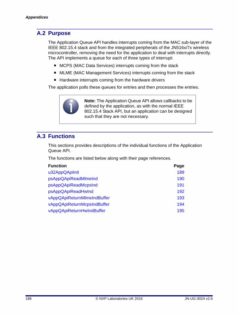
Appendices
A.2 Purpose
The Application Queue API handles interrupts coming from the MAC sub-layer of the IEEE 802.15.4 stack and from the integrated peripherals of the JN516x/7x wireless microcontroller, removing the need for the application to deal with interrupts directly. The API implements a queue for each of three types of interrupt:
MCPS (MAC Data Services) interrupts coming from the stack
MLME (MAC Management Services) interrupts coming from the stack
Hardware interrupts coming from the hardware drivers
The application polls these queues for entries and then processes the entries.
A.3 Functions
This sections provides descriptions of the individual functions of the Application Queue API.
The functions are listed below along with their page references.
Function Page
u32AppQApiInit 189
psAppQApiReadMlmeInd 190
psAppQApiReadMcpsInd 191
psAppQApiReadHwInd 192
vAppQApiReturnMlmeIndBuffer 193
vAppQApiReturnMcpsIndBuffer 194
vAppQApiReturnHwIndBuffer 195
Note: The Application Queue API allows callbacks to be defined by the application, as with the normal IEEE 802.15.4 Stack API, but an application can be designed such that they are not necessary.
188 © NXP Laboratories UK 2016 JN-UG-3024 v2.6

IEEE 802.15.4 StackUser Guide
u32AppQApiInit
Description
This function initialises the Application Queue API, as well as the underlying 802.15.4 Stack API and hence the whole 802.15.4 stack. The function creates queues for storing a number of upward messages (MLME indications and confirmations, MCPS indications and confirmations, Integrated Peripherals API indications) and registers itself with the lower layers so that all such messages go through it. The function registers user-defined callback functions for the three queues:
Callback function for upward MLME indications and confirmations
Callback function for upward MCPS indications and confirmations
Callback function for upward indications from the Integrated Peripherals API
The callback functions are optional and should only be needed if the application must be notified as soon as a message is placed in the queues.
The prototypes for all three callback functions take no parameters and return void.
Parameters
prMlmeCallback Pointer to optional callback function for upward MLME indications and confirmations. If a callback is not required, a value of NULL must be used.
prMcpsCallback Pointer to optional callback function for upward MCPS indications and confirmations. If a callback is not required, a value of NULL must be used.
prHwCallback Pointer to optional callback function for upward indications from the Integrated Peripherals API. If a callback is not required, a value of NULL must be used.
Returns
0 if initialisation failed.
Otherwise, the 32-bit version number of the IEEE 802.15.4 stack (most significant 16 bits are major revision, least significant 16 bits are patch revision/minor revision).
uint32 u32AppQApiInit(PR_QIND_CALLBACK prMlmeCallback, PR_QIND_CALLBACK prMcpsCallback, PR_HWQINT_CALLBACK prHwCallback);
JN-UG-3024 v2.6 © NXP Laboratories UK 2016 189

Appendices
psAppQApiReadMlmeInd
Description
This function enables the application to poll the MLME indication/confirmation queue. If an event is present in the queue, the application can process it. Once processing has finished, the buffer (that contained the event) must be returned to the Application Queue API using the vAppQApiReturnMlmeIndBuffer() function. The result is returned in the structure MAC_MlmeDcfmInd_s (for details of this structure, refer to Section 6.1.3).
Parameters
None
Returns
MAC_MlmeDcfmInd_s
Pointer to a buffer containing an MLME indication or confirmation, or NULL if the queue is empty.
MAC_MlmeDcfmInd_s *psAppQApiReadMlmeInd(void);
190 © NXP Laboratories UK 2016 JN-UG-3024 v2.6
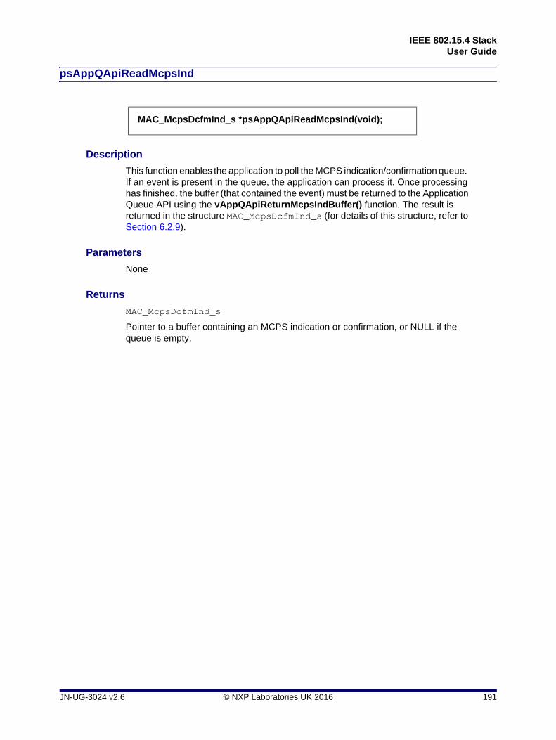
IEEE 802.15.4 StackUser Guide
psAppQApiReadMcpsInd
Description
This function enables the application to poll the MCPS indication/confirmation queue. If an event is present in the queue, the application can process it. Once processing has finished, the buffer (that contained the event) must be returned to the Application Queue API using the vAppQApiReturnMcpsIndBuffer() function. The result is returned in the structure MAC_McpsDcfmInd_s (for details of this structure, refer to Section 6.2.9).
Parameters
None
Returns
MAC_McpsDcfmInd_s
Pointer to a buffer containing an MCPS indication or confirmation, or NULL if the queue is empty.
MAC_McpsDcfmInd_s *psAppQApiReadMcpsInd(void);
JN-UG-3024 v2.6 © NXP Laboratories UK 2016 191

Appendices
psAppQApiReadHwInd
Description
This function enables the application to poll the hardware indication queue. If an event is present in the queue, the application can process it. Once processing has finished, the buffer (that contained the event) must be returned to the Application Queue API using the vAppQApiReturnHwIndBuffer() function. The result is returned in the structure AppQApiHwInd_s, detailed below.
Parameters
None
Returns
AppQApiHwInd_s, which has the following definition:
typedef struct
{
uint32 u32DeviceId;
uint32 u32ItemBitmap;
} AppQApiHwInd_s;
u32DeviceId and u32ItemBitmap are detailed in the JN516x Integrated Peripherals API User Guide (JN-UG-3087) and JN517x Integrated Peripherals API User Guide (JN-UG-3118).
AppQApiHwInd_s * psAppQApiReadHwInd (void);
192 © NXP Laboratories UK 2016 JN-UG-3024 v2.6
IEEE 802.15.4 StackUser Guide
vAppQApiReturnMlmeIndBuffer
Description
This function allows the application to return an MLME buffer previously passed up to the application. Once returned, the buffer can be re-used to store and pass another message.
Parameters
*psBuffer Pointer to MLME buffer to be returned
Returns
None
void vAppQApiReturnMlmeIndBuffer(MAC_MlmeDcfmInd_s *psBuffer);
JN-UG-3024 v2.6 © NXP Laboratories UK 2016 193

Appendices
vAppQApiReturnMcpsIndBuffer
Description
This function allows the application to return an MCPS buffer previously passed up to the application. Once returned, the buffer can be re-used to store and pass another message.
Parameters
*psBuffer Pointer to MCPS buffer to be returned
Returns
None
void vAppQApiReturnMcpsIndBuffer(MAC_McpsDcfmInd_s *psBuffer);
194 © NXP Laboratories UK 2016 JN-UG-3024 v2.6

IEEE 802.15.4 StackUser Guide
vAppQApiReturnHwIndBuffer
Description
This function allows the application to return a hardware event buffer previously passed up to the application from the Integrated Peripherals API. Once returned, the buffer can be re-used to store and pass another message.
Parameters
*psBuffer Pointer to hardware event buffer to be returned.
Returns
None
void vAppQApiReturnHwIndBuffer(AppQApiHwInd_s *psBuffer);
JN-UG-3024 v2.6 © NXP Laboratories UK 2016 195

Appendices
196 © NXP Laboratories UK 2016 JN-UG-3024 v2.6

IEEE 802.15.4 StackUser Guide
B. Notes on IEEE 802.15.4-2006 Security
The IEEE 802.15.4 standard defines the security features that may be incorporated in an IEEE 802.15.4-based network. These features differ between the 2003 and 2006 versions of the standard (as indicated in Section 1.16). The NXP implementation of IEEE 802.15.4 incorporates both versions, but NXP provide example code only for the 2006 version of security - this is available in the Application Note 802.15.4 Home Sensor Demonstration for JN516x (JN-AN-1180). This appendix provides useful information on IEEE 802.15.4-2006 security.
B.1 Security Features
IEEE 802.15.4 security is introduced in Section 1.16. The information provided in this appendix is concerned with ‘Secured mode’ for the IEEE 802.15.4-2006 standard. Security is implemented as a ‘security suite’ which can be selected from a set of seven (as indicated in Table 4 on page 45 for IEEE 802.15.4-2006 security).
All the security suites of the IEEE 802.15.4-2006 standard are based on AES-CCM* algorithms, and implement access control and sequential freshness (replay protection). Optionally, encryption (data confidentiality) and integrity (data authenticity) can be implemented, depending on the chosen security suite.
The above security features require look-up tables to be present on the participating devices, including:
Key table: Contains key descriptors with related key-specific information - each entry includes a key and the following sub-tables:
Key ID Look-up: Contains a list of data values used to identify the security key. Each value is 5 or 9 bytes long and depends on the 'key identifier mode', 'key source' and 'key index' values being used (specified in the MCPS-Data.Request for outgoing frames and in the auxiliary security header for incoming frames) and various address values. The key index value is included within these bytes. Hence, it is possible for the application (for outgoing frames or incoming frame) to influence the choice of key independently of the address and mode. When looking for a key to use with a frame, the MAC searches every record in the Key table and each record in each Key ID Look-up sub-table until it finds a matching ID.
Key device descriptors: Contains a list of key device descriptors, each entry containing a handle to a device descriptor (containing device addresses) and flags for specific security rules. This sub-table links the key to specific device addresses. Having found a matching ID value in the Key ID Look-up sub-table, the MAC searches the list of key device descriptors to find a matching address.
Note: The application coding of IEEE 802.15.4-2006 security is complex and you are advised to use the example code provided in the Application Note 802.15.4 Home Sensor Demonstration for JN516x (JN-AN-1180) as a basis for your own application development.
JN-UG-3024 v2.6 © NXP Laboratories UK 2016 197

Appendices
Key usage descriptors: Contains a list of descriptors that indicate the frame types (and, for command frames, command types) for which the key is valid. Hence, it is possible to restrict the key to specific frame types.
Device table: Contains device descriptors (device-specific addressing information and security-related information) that are combined with information from the Key table to secure outgoing frames and unsecure incoming frames
Minimum Security Level table: Contains information concerning the minimum security level that the device expects to have been applied to a frame by the originator, depending on frame type and the command frame identifier (for a MAC command frame)
The above tables are held in the PAN Information Base (PIB) on a device - refer to Section 8.3 for the relevant PIB attributes and Section 6.3.9 through to Section 6.3.14 for the relevant structures. More detailed descriptions of the tables can be found in the IEEE 802.15.4-2006 standard.
IEEE 802.15.4-2006 security provides the following features (based on the use of the above look-up tables):
Black-listing of device addresses
Minimum acceptable security level for incoming frames - different levels for different frame types and exemption for specific devices are possible
Ability for the application to select more than one key for the same device:
Key Index to allow selection of more than one key using the same look-up method (but not for Key Identifier Mode 0 - see below)
Key Identifier Mode to determine how the address fields of a frame and the au8macDefaultKeySource attribute are used in the look-up procedure - this mode is available in the following variations (0, 1, 2 and 3):
0: Key is determined from the destination (on transmit) or source (on receive) address fields within the frame, or the PAN Co-ordinator address if those fields are not present
1: Key is determined from au8macDefaultKeySource and the Key index
2/3: Key is determined from data passed in from the application (on transmit) or carried unencrypted in the frame (on receive), and from the Key index
Frame counter for outgoing frames and a record of the frame counter for incoming frames from all other devices, eliminating replay attacks
198 © NXP Laboratories UK 2016 JN-UG-3024 v2.6

IEEE 802.15.4 StackUser Guide
B.2 Security Procedures and Examples
The procedures for securing outgoing frames and unsecuring incoming frames are fully detailed in the IEEE 802.15.4-2006 standard, to which you should refer during your application development. You are also advised to use the Application Note 802.15.4 Home Sensor Demonstration for JN516x (JN-AN-1180) as a basis for implementing security in your applications.
Note the following:
You must call the function vAppApiSetSecurityMode() in your application to select the type of security (2003 or 2006) that your application will implement - this function is detailed in Section 5.1.
The look-up tables (introduced in Appendix B.1) are held in the PAN Information Base (PIB) on a device. The PIB attributes that relate to security are listed and described in Section 8.3.
The ways in which the look-up tables relate to each other are illustrated in Table 20 on page 200. The terminology used is the same as that used within the NXP source code. Note that the tables are depicted as a series of entries layered on top of one another.
An example of a security implementation in a network is illustrated in Table 21 on page 201, which shows how a single network key could be shared by 20 nodes and used for all data frames. Key Identifier Mode 1 (see Appendix B.1) is assumed, which means that the Key ID look-up uses the values from au8macDefaultKeySource and hence psKeyIdLookupDescriptor can be the same for all nodes.
JN-UG-3024 v2.6 © NXP Laboratories UK 2016 199

Appendices
Figure 20: Relationships Between Security Tables
MA
C_
Key
Usa
geD
escr
ipto
r_s
uin
t8u
8Fra
me
Typ
e;
uin
t8u
8Co
mm
and
Fra
me
Iden
tifie
r;
MA
C_K
eyU
sage
Des
crip
tor_
s
uin
t8u8
Fra
meT
ype;
uin
t8u8
Com
man
dFra
me
Ide
ntif
ier;
MA
C_
Key
Dev
iceD
escr
ipto
r_s
uin
t32
u32
Dev
ice
De
scrip
torH
and
le;
bool
_t
bU
niq
ueD
evi
ce;
bool
_t
bB
lack
liste
d;
u32
De
vice
De
scrip
torH
and
le in
ind
ex in
to P
IB-
>ps
Ma
cDev
ice
Ta
ble
arr
ay
MA
C_
Key
Dev
iceD
escr
ipto
r_s
uin
t32
u32D
evi
ceD
esc
ripto
rHa
ndle
;b
ool_
tbU
niq
ueD
evic
e;
boo
l_t
bBla
cklis
ted;
u32D
evi
ceD
escr
ipto
rHan
dle
in in
dex
into
PIB
->
psM
acD
evi
ceT
abl
e a
rray
MA
C_K
eyId
Loo
kupD
escr
ipto
r_s
uin
t8
a
u8Lo
oku
pDa
ta[9
];ui
nt8
u8L
ooku
pD
ataS
ize
;
MA
C_K
eyId
Loo
kupD
esc
ripto
r_s
uin
t8
au
8Loo
kupD
ata
[9];
uin
t8
u8
Look
upD
ata
Siz
e;
MA
C_
Dev
ice
De
scrip
tor_
s
uin
t16
u1
6Pan
Id;
uin
t16
u1
6Sho
rt;
MA
C_
Ext
Add
r_s
sExt
;u
int3
2
u32F
ram
eC
ou
nte
r;b
ool_
t
bExe
mpt
;
MA
C_
Dev
ice
Des
crip
tor_
s
uin
t16
u
16P
anI
d;ui
nt1
6
u16
Sh
ort;
MA
C_E
xtA
ddr
_s
sExt
;ui
nt3
2
u32
Fra
meC
oun
ter;
bool
_t
b
Exe
mp
t;
MA
C_S
ecu
rityL
evel
Des
crip
tor_
s
uin
t8u
8Fra
me
Typ
e;
uin
t8u
8Co
mm
and
Fra
meI
de
ntifi
er;
uin
t8u
8Min
imum
Sec
urity
;
boo
l_t
bO
verid
eSec
urit
yMin
imu
m;
MA
C_S
ecu
rityL
evel
Des
crip
tor_
s
uin
t8u
8Fra
meT
ype
;ui
nt8
u8C
omm
andF
ram
eId
entif
ier;
uin
t8u
8Min
imum
Se
curi
ty;
bool
_t
bO
veri
deS
ecu
rity
Min
imum
;
MA
C_
Key
Des
crip
tor_
sM
AC
_K
eyI
dLoo
kupD
esc
ripto
r_s
*psK
eyId
Loo
kup
Des
crip
tor; u
int8
u8
Ke
yIdL
ook
upE
ntri
es;
MA
C_
Ke
yDe
vice
De
scrip
tor_
s
*psK
eyD
evi
ceL
ist;
uin
t8
u8K
eyD
evic
eLi
stE
ntri
es;
MA
C_
Ke
yUsa
geD
escr
ipto
r_s
*p
sKey
Usa
geLi
st;
uin
t8
u8K
eyU
sag
eLis
tEn
trie
s;
uin
t32
au32
Sym
met
ricK
ey[
4];
MA
C_K
eyId
Loo
kup
Des
crip
tor_
s *p
sKe
yId
Look
up
De
scri
pto
r; uin
t8
u8K
eyId
Loo
kup
En
trie
s;M
AC
_Key
De
vice
Des
crip
tor_
s
*psK
eyD
evic
eLi
st;
uin
t8
u8K
eyD
evi
ceL
istE
ntr
ies;
MA
C_K
eyU
sage
Des
crip
tor_
s
*psK
eyU
sag
eLi
st;
uin
t8
u8K
eyU
sage
List
Ent
ries;
uin
t32
au3
2Sym
me
tric
Ke
y[4]
;
MA
C_
Key
Des
crip
tor_
sP
IB->
psM
acK
eyT
ab
le
MA
C_K
eyD
escr
ipto
r_s
*
Nu
mbe
r o
f ar
ray
ele
me
nts
is in
P
IB->
u8M
acK
eyT
ab
leE
ntr
ies
PIB
->ps
Mac
Sec
urit
yLev
elT
able
MA
C_S
ecu
rity
Leve
lDes
crip
tor_
s *
Nu
mbe
r o
f ar
ray
ele
me
nts
is in
P
IB->
u8M
acS
ecu
irtyL
evel
Tab
leE
ntri
es
PIB
->p
sMac
Dev
iceT
able
MA
C_D
evic
eDes
crip
tor_
s *
Nu
mbe
r o
f ar
ray
ele
me
nts
is in
P
IB->
u8M
acD
evic
eT
able
Ent
ries
MA
C_K
eyU
sage
Des
crip
tor_
s
uin
t8u
8F
ram
eT
ype
;u
int8
u8
Co
mm
and
Fra
meI
dent
ifie
r;
MA
C_K
eyD
escr
ipto
r_s
MA
C_
Ke
yId
Look
upD
esc
ripto
r_s
*psK
eyI
dLo
oku
pDe
scrip
tor; u
int8
u8
Ke
yId
Look
up
En
trie
s;M
AC
_K
eyD
evic
eD
escr
ipto
r_s
*p
sKe
yDev
ice
List
;u
int8
u8
Ke
yDev
ice
List
Ent
ries;
MA
C_
Ke
yUsa
geD
esc
ripto
r_s
*p
sKe
yUsa
geL
ist;
uin
t8
u8K
eyU
sag
eLi
stE
ntrie
s;
uin
t32
au
32S
ymm
etr
icK
ey[4
];
MA
C_D
evic
eDe
scrip
tor_
s
uin
t16
u1
6P
anId
;u
int1
6
u16
Sho
rt;
MA
C_
Ext
Ad
dr_s
sE
xt;
uin
t32
u3
2F
ram
eC
ount
er;
boo
l_t
bE
xem
pt;
MA
C_
Sec
urity
Leve
lDes
crip
tor_
s
uin
t8u8
Fra
meT
ype;
uin
t8u8
Com
man
dFra
me
Ide
ntifi
er;
uint
8u8
Min
imu
mS
ecur
ity;
boo
l_t
bOve
ride
Se
curi
tyM
inim
um
;
MA
C_K
eyId
Look
upD
esc
ripto
r_s
uin
t8
a
u8L
ooku
pD
ata
[9];
uin
t8
u
8Lo
oku
pDa
taS
ize;
MA
C_K
eyD
evic
eDes
crip
tor_
su
int3
2u
32D
evic
eD
escr
ipto
rHan
dle
;b
ool_
tb
Uni
que
Dev
ice
;b
ool_
tb
Bla
cklis
ted
;
u32
Dev
ice
Des
crip
torH
an
dle
in in
dex
into
P
IB->
psM
acD
evic
eT
able
arr
ay
200 © NXP Laboratories UK 2016 JN-UG-3024 v2.6

IEEE 802.15.4 StackUser Guide
Figure 21: Security Example
MA
C_K
eyD
evic
eDes
crip
tor_
su
int3
2u
32D
evic
eD
escr
ipto
rHan
dle
;b
ool_
tb
Uni
que
Dev
ice
;b
ool_
tb
Bla
cklis
ted
;
u32D
evi
ceD
escr
ipto
rHan
dle
in in
dex
into
PIB
->
psM
acD
evi
ceT
abl
e a
rray
MA
C_K
eyD
evi
ceD
esc
ripto
r_s
uint
32u
32D
evi
ceD
esc
ripto
rHa
ndle
;bo
ol_
tb
Un
iqu
eDe
vice
;bo
ol_
tb
Bla
cklis
ted;
u32
Dev
ice
De
scri
pto
rHa
ndle
in in
dex
into
PIB
->
psM
acD
evic
eT
able
arr
ay
MA
C_D
evic
eDes
crip
tor_
s
uin
t16
u
16P
anI
d;ui
nt1
6
u16
Sh
ort;
MA
C_E
xtA
ddr
_s
sExt
;ui
nt3
2
u32
Fra
meC
oun
ter;
bool
_t
b
Exe
mpt
;
MA
C_D
evic
eDes
crip
tor_
s
uin
t16
u1
6Pan
Id;
uin
t16
u1
6Sho
rt;
MA
C_
Ext
Ad
dr_s
sE
xt;
uin
t32
u3
2Fra
me
Cou
nter
;b
ool_
t
bExe
mp
t;
PIB
->ps
Mac
Key
Tab
le
MA
C_K
eyD
escr
ipto
r_s
*
Num
ber
of a
rra
y el
em
ent
s is
in
PIB
->u
8M
acK
eyT
able
Ent
ries
PIB
->ps
Mac
Sec
urity
Leve
lTab
le
MA
C_S
ecur
ityLe
velD
escr
ipto
r_s
*
Num
ber
of a
rra
y el
em
ent
s is
in
PIB
->u
8Mac
Sec
uirt
yLe
velT
abl
eE
ntr
ies
PIB
->ps
Mac
De
vice
Tab
le
MA
C_
De
vice
De
scri
pto
r_s
*
Num
ber
of a
rra
y el
em
ent
s is
in
PIB
->u
8Mac
De
vice
Ta
ble
En
trie
s
MA
C_K
eyU
sage
De
scrip
tor_
s
uin
t8u8
Fra
meT
ype;
uin
t8u8
Com
ma
ndF
ram
eId
ent
ifie
r;
MA
C_K
eyD
esc
ript
or_s
MA
C_K
eyId
Loo
kup
Des
crip
tor_
s *p
sKey
IdL
ooku
pD
escr
ipt
or;
uin
t8
u8
Ke
yIdL
ooku
pEnt
ries
;M
AC
_Key
De
vice
De
scrip
tor_
s
*psK
eyD
evi
ceL
ist;
uin
t8
u8
Ke
yDe
vice
Lis
tEn
trie
s;M
AC
_Key
Usa
geD
escr
ipto
r_s
*p
sKey
Usa
geLi
st;
uin
t8
u8
Ke
yUsa
geL
istE
ntr
ies;
uin
t32
au
32S
ymm
etri
cKe
y[4
];
MA
C_D
evic
eDes
crip
tor_
s
uin
t16
u
16P
an
Id;
uin
t16
u
16S
ho
rt;
MA
C_E
xtA
ddr_
s sE
xt;
uin
t32
u
32F
ram
eCo
unte
r;bo
ol_
t
bE
xem
pt;
MA
C_S
ecur
ityLe
velD
escr
ipto
r_s
uin
t8u
8Fra
me
Typ
e;
uin
t8u
8Co
mm
and
Fra
meI
den
tifie
r;ui
nt8
u8M
inim
umS
ecu
rity;
boo
l_t
bO
verid
eSec
urit
yMin
imu
m;
MA
C_K
eyId
Look
upD
escr
ipto
r_s
uin
t8
au
8Loo
kup
Dat
a[9
];u
int8
u8Lo
oku
pDa
taS
ize;
MA
C_K
eyD
evic
eDes
crip
tor_
su
int3
2u3
2De
vice
Des
crip
torH
andl
e;
boo
l_t
bUn
ique
Dev
ice
;b
ool_
tbB
lack
liste
d;
u32D
evi
ceD
esc
ripto
rHa
ndle
in in
dex
into
P
IB->
psM
acD
evi
ceT
abl
e a
rray
x1 x20
x1
x1
x1 x20
JN-UG-3024 v2.6 © NXP Laboratories UK 2016 201

Appendices
B.3 Performance Considerations
B.3.1 Memory Usage
Selection of specific modes minimises the amount of RAM required by the security data. Key Identifier Modes 1, 2 and 3 provide the minimum space for a given size of network, as they allow one key ID look-up descriptor to be used for all devices.
If multiple keys are required, it is possible to share the sub-tables between them.
B.3.2 Frame Size
The auxiliary security header in an IEEE 802.15.4 MAC frame is at least 5 bytes long. In addition, the Key Identifier modes add extra bytes, as follows:
Different security levels also add a checksum of 0 (no MIC), 4, 8 or 16 bytes.
B.3.3 Conclusion
Key Identifier Mode 0 provides the best frame size but Key Identifier Mode 1 uses frames that are only one byte larger while allowing for smaller data tables. Therefore, in general use, Key Identifier Mode 1 provides the best compromise between memory usage and frame size.
Key Identifier Mode Additional Header Data (bytes)
0 0
1 1
2 5
3 9
Table 13: Extra Header Data Bytes for Key Identifier Modes
202 © NXP Laboratories UK 2016 JN-UG-3024 v2.6

IEEE 802.15.4 StackUser Guide
Revision History
Version Date Comments
1.0 19-Sep-2006 Initial release
1.1 06-Oct-2006 Clarification of network topologies in relation to IEEE 802.15.4 standard
2.0 11-Feb-2014 • Updated for JN516x and JN514x families of wireless microcontroller
• Incorporates information from former 802.15.4 Stack API Reference Manual (JN-RM-2002), IEEE 802.15.4 Application Development Reference Manual (JN-RM-2024) and Application Queue API Reference Manual (JN-RM-2025)
2.1 16-June-2014 Updated for new JN516x SDK installers (JN-SW-4163, JN-SW-4141) and removed support for JN514x
2.2 15-Sep-2014 Updated branding
2.3 22-Apr-2015 Updated radio transmission power section and other modifications/corrections made
2.4 24-June-2015 Clarified build instructions for targeting different JN516x chip types
2.5 25-Feb-2016 Updated for the JN517x family of wireless microcontrollers and the JN517x IEEE 802.15.4 SDK (JN-SW-4263)
2.6 22-June-2016 • Migrated JN516x application template information to the Application Note JN-AN-1174
• Added referral to JN517x IEEE 802.15.4 SDK Release Notes for required version of LPCXpresso
JN-UG-3024 v2.6 © NXP Laboratories UK 2016 203

IEEE 802.15.4 StackUser Guide
Important Notice
Limited warranty and liability - Information in this document is believed to be accurate and reliable. However, NXP Semiconductors does not give any representations or warranties, expressed or implied, as to the accuracy or completeness of such information and shall have no liability for the consequences of use of such information. NXP Semiconductors takes no responsibility for the content in this document if provided by an information source outside of NXP Semiconductors.
In no event shall NXP Semiconductors be liable for any indirect, incidental, punitive, special or consequential damages (including - without limitation - lost profits, lost savings, business interruption, costs related to the removal or replacement of any products or rework charges) whether or not such damages are based on tort (including negligence), warranty, breach of contract or any other legal theory.
Notwithstanding any damages that customer might incur for any reason whatsoever, NXP Semiconductors' aggregate and cumulative liability towards customer for the products described herein shall be limited in accordance with the Terms and conditions of commercial sale of NXP Semiconductors.
Right to make changes - NXP Semiconductors reserves the right to make changes to information published in this document, including without limitation specifications and product descriptions, at any time and without notice. This document supersedes and replaces all information supplied prior to the publication hereof.
Suitability for use - NXP Semiconductors products are not designed, authorized or warranted to be suitable for use in life support, life-critical or safety-critical systems or equipment, nor in applications where failure or malfunction of an NXP Semiconductors product can reasonably be expected to result in personal injury, death or severe property or environmental damage. NXP Semiconductors and its suppliers accept no liability for inclusion and/or use of NXP Semiconductors products in such equipment or applications and therefore such inclusion and/or use is at the customer's own risk.
Applications - Applications that are described herein for any of these products are for illustrative purposes only. NXP Semiconductors makes no representation or warranty that such applications will be suitable for the specified use without further testing or modification.
Customers are responsible for the design and operation of their applications and products using NXP Semiconductors products, and NXP Semiconductors accepts no liability for any assistance with applications or customer product design. It is customer's sole responsibility to determine whether the NXP Semiconductors product is suitable and fit for the customer's applications and products planned, as well as for the planned application and use of customer's third party customer(s). Customers should provide appropriate design and operating safeguards to minimize the risks associated with their applications and products.
NXP Semiconductors does not accept any liability related to any default, damage, costs or problem which is based on any weakness or default in the customer's applications or products, or the application or use by customer's third party customer(s). Customer is responsible for doing all necessary testing for the customer's applications and products using NXP Semiconductors products in order to avoid a default of the applications and the products or of the application or use by customer's third party customer(s). NXP does not accept any liability in this respect.
Export control - This document as well as the item(s) described herein may be subject to export control regulations. Export might require a prior authorization from competent authorities.
NXP Semiconductors
For online support resources and contact details of your local NXP office or distributor, refer to:
www.nxp.com
204 © NXP Laboratories UK 2016 JN-UG-3024 v2.6