ieee p802.11s™/d1.07 draft standard for ...nemo/tmp/draft_p802.11s_d1.07.pdf · d1.01 2007-03-09...
TRANSCRIPT

IEEE P802.11s/D1.07, September 2007
123456789
1011121314151617181920212223242526272829303132333435363738394041424344454647484950515253545556575859606162636465
IEEE P802.11s™/D1.07
Draft STANDARD for Information Technology-Telecommunications and information exchange between systems-Local and metropolitan area networks-Specific requirements-
Part 11: Wireless LAN Medium Access Control (MAC) and Physical Layer (PHY) specifications
Amendment <number>: Mesh Networking
EDITORIAL NOTE—the amendment number will be inserted by IEEE-SA editorial staff during preparation for publication.
Prepared by the 802.11 Working Group of the IEEE 802 Committee
Copyright © 2007 by the IEEE.
3 Park AvenueNew York, NY 10016-5997, USAAll rights reserved.
This document is an unapproved draft of a proposed IEEE Standard. As such, this document is subject tochange. USE AT YOUR OWN RISK! Because this is an unapproved draft, this document must not beutilized for any conformance/compliance purposes. Permission is hereby granted for IEEE StandardsCommittee participants to reproduce this document for purposes of IEEE standardization activities only.Prior to submitting this document to another standards development organization for standardizationactivities, permission must first be obtained from the Manager, Standards Intellectual Property, IEEEStandards Activities Department. Other entities seeking permission to reproduce this document, in whole orin part, must obtain permission from the Manager, Standards Intellectual Property, IEEE StandardsActivities Department.
IEEE Standards Activities DepartmentStandards Licensing and Contracts445 Hoes Lane, P.O. Box 1331Piscataway, NJ 08855-1331, USA
Copyright © 2007 IEEE. All rights reserved. iThis is an unapproved IEEE Standards Draft, subject to change.

IEEE P802.11s/D1.07, September 2007
123456789
1011121314151617181920212223242526272829303132333435363738394041424344454647484950515253545556575859606162636465
Abstract: This amendment defines an IEEE 802.11 Wireless LAN (WLAN) Mesh using the IEEE802.11 MAC/PHY layers that supports both individually addressed and group addressed deliveryover self-configuring multi-hop topologies.
Keywords: Wireless LAN, Medium Access Control, Mesh, Multi-hop
ii Copyright © 2007 IEEE. All rights reserved.This is an unapproved IEEE Standards Draft, subject to change.

IEEE P802.11s/D1.07, September 2007
123456789
1011121314151617181920212223242526272829303132333435363738394041424344454647484950515253545556575859606162636465
Introduction
(This introduction is not part of IEEE P802.11s/D1.07, Draft Amendment to Standard forInformation Technology - Telecommunications and Information Exchange Between Systems - LAN/MAN Specific Requirements - Part 11: Wireless Medium Access Control (MAC) and physical layer(PHY) specifications: Amendment: Mesh Networking.)
This amendment specifies enhancements to the following draft standard and draft amendments, in order tosupport mesh networking:
— IEEE P802.11-2007— IEEE P802.11k D7.0— IEEE P802.11n D2.02— IEEE P802.11r D5.0— IEEE P802.11w D2.0— IEEE P802.11y D2.0
The networks described in this amendment make use of layer-2 mesh path selection and forwarding (that is,a mesh network that performs routing at the link layer). Mesh networks have advantageous properties interms of robustness, range extension and density, but also have potential challenges such as power consump-tion and security. This amendment is specifically designed to address these challenges.
Notice to users
Errata
Errata, if any, for this and all other standards can be accessed at the following URL: http://standards.ieee.org/reading/ieee/updates/errata/index.html. Users are encouraged to check this URL forerrata periodically.
Interpretations
Current interpretations can be accessed at the following URL: http://standards.ieee.org/reading/ieee/interp/index.html.
Patents
Attention is called to the possibility that implementation of this standard may require use of subject mattercovered by patent rights. By publication of this standard, no position is taken with respect to the existence orvalidity of any patent rights in connection therewith. The IEEE shall not be responsible for identifyingpatents or patent applications for which a license may be required to implement an IEEE standard or forconducting inquiries into the legal validity or scope of those patents that are brought to its attention. A patentholder or patent applicant has filed a statement of assurance that it will grant licenses under these rightswithout compensation or under reasonable rates and nondiscriminatory, reasonable terms and conditions toapplicants desiring to obtain such licenses. The IEEE makes no representation as to the reasonableness ofrates, terms, and conditions of the license agreements offered by patent holders or patent applicants. Furtherinformation may be obtained from the IEEE Standards Department.
Copyright © 2007 IEEE. All rights reserved. iiiThis is an unapproved IEEE Standards Draft, subject to change.
IEEE P802.11s/D1.07, September 2007
123456789
1011121314151617181920212223242526272829303132333435363738394041424344454647484950515253545556575859606162636465
Participants
At the time this draft amendment to standard was completed, the 802.11 Working Group had the followingmembership:
Stuart J. Kerry, ChairAl Petrick and Harry Worstell, Vice-chair
Tim Godfrey, Secretary
EDITORIAL NOTE—a three column list of voting members of 802.11 on the day the draft was sent for sponsor ballot will be inserted
The following were officers of Task Group s:Donald E. Eastlake 3rd, ChairStephen Rayment, Secretary
W. Steven Conner, Technical Editor
The following members of the balloting committee voted on this Standard. Balloters may have voted forapproval, disapproval, or abstention.
EDITORIAL NOTE—a three-column list of responding sponsor ballot members will be inserted by IEEE staff
iv Copyright © 2007 IEEE. All rights reserved.This is an unapproved IEEE Standards Draft, subject to change.

IEEE P802.11s/D1.07, September 2007
123456789
1011121314151617181920212223242526272829303132333435363738394041424344454647484950515253545556575859606162636465
Editorial Notes
EDITORIAL NOTE—Two forms of editorial markup are used: Notes and Comments. Editorial Notes and Editorial Comments are not part of the amendment and will be removed before it is published, together with any other contents in this subclause. This paragraph is an example of how an Editorial Note is marked. Editorial Comments are marked (Ed:), and contain references to submissions or comment resolutions to track the origin of changes.
EDITORIAL NOTE—Headings with empty content or Headings preceding editing instructions that modify the contents of the referenced subclause are there to provide context to the reader of this document, they have no other significance.
EDITORIAL NOTE—Except when referring to tables and figures that exist in the baseline, figure and table numbers are preceded by “s” and are assigned sequentially. This will be changed prior to sponsor ballot.
EDITORIAL NOTE—The default IEEE-SA style for tables is to “float”. This means that they be repositioned later, usually at the head of the next page, to avoid splitting the table and reduce the amount of blank space. The table can appear to move out of the subclause it is referenced first from, and can even split a paragraph. This is the intended IEEE-SA behavior, please do not report it as a defect in the draft.
EDITORIAL NOTE—Line numbering is only approximate. This is a limitation of the FrameMaker tool. Whitespace between paragraphs is part of the IEEE-SA style, as defined in their templates. The combination of these two facts leads to the appearance of blank lines in the draft between every paragraph. Please do not report this as an editorial defect as it is the unavoidable behavior.
EDITORIAL NOTE—New subclauses are generally introduced by an editorial instruction “insert the following new subclause”. New subclause headings are generally introduced by an editorial instruction “insert the following new subclause heading”. Each new heading or subclause has its own editorial instruction. The instruction intentionally does not include where to insert the subclause because that is determined uniquely by the subclause number.
EDITORIAL NOTE—Pronunciation. It is assumed that while reading the spec aloud, a reader will read “MP” as “emm pea” rather than read it as “mesh point”. This determines the spelling of the indefinite article to be “an” rather than “a”
.
Copyright © 2007 IEEE. All rights reserved. iThis is an unapproved IEEE Standards Draft, subject to change.

IEEE P802.11s/D1.07, September 2007
123456789
1011121314151617181920212223242526272829303132333435363738394041424344454647484950515253545556575859606162636465
Status of this document
Draft Date Changes
D1.01 2007-03-09 Conversion of draft from Word format to FrameMaker format.Implementation of most comment resolutions marked as Accept/Counter in 11-07/23r5 and 11-07/23r6 adopted by motions duringJanuary 2007 meeting. Implemented resolutions are marked with“D1.01” in “Edited in Draft” column of 11-07/23r20.
D1.02 2007-03-27 Implementation of resolutions marked with D1.02 in “Edited inDraft” column of 11-07/23r26.
D1.03 2007-04-06 Updated draft to correspond to latest baseline documents: IEEEP802.11-2007, .11k D7.0, .11r D5.0, .11y D2.0. Editorial fixes toimplementation of changes in 11-07/286r0 and 11-07/440r0. Imple-mentation of resolutions marked with D1.03 in “Edited in Draft” col-umn of 11-07/23r27.
D1.04 2007-06-06 Implementation of draft changes adopted in the May 2007 interimmeeting in Montreal, including resolutions marked with D1.04 in“Edited in Draft” column of 11-07/23r36. Updated draft to corre-spond to latest baseline documents: IEEE .11n D2.02, .11w D2.0.Editorial updates for consistency with .11 WG editors best practices.
D1.05 2007-06-25 Updated draft to reflect editorial revisions in published baseline doc-ument P802.11-2007 (primarily changes to figure and table num-bers). Fixed formatting issues in tables throughout clause 11A.Editorial fixes to implementation of changes in 11-07/618r0 and 11-07/631r1. Cleanup of editorial notes throughout the draft.
D1.06 2007-07-24 Implementation of resolutions marked with D1.06 in “Edited inDraft” column of 11-07/23r41.
D1.07 2007-09-30 Implementation of all changes to the draft adopted by motions at theSeptember meeting in Waikoloa, including resolutions marked withD1.07 in “Edited in Draft” column of 11-07/23r50.
Copyright © 2007 IEEE. All rights reserved. iiThis is an unapproved IEEE Standards Draft, subject to change.

IEEE P802.11s/D1.07, September 2007
123456789
1011121314151617181920212223242526272829303132333435363738394041424344454647484950515253545556575859606162636465
Table of Contents
3. Definitions ................................................................................................................................................. 2
4. Abbreviations and acronyms ..................................................................................................................... 3
5. General description .................................................................................................................................... 4
5.2 Components of the IEEE 802.11 architecture ............................................................................. 45.2.9 Wireless LAN mesh..................................................................................................... 4
5.2.9.1 Introduction to mesh ................................................................................ 45.2.9.2 Mesh network model ............................................................................... 55.2.9.3 Organization of mesh subclauses............................................................. 6
7. Frame formats ............................................................................................................................................ 7
7.1 MAC frame formats..................................................................................................................... 77.1.2 General frame format................................................................................................... 77.1.3 Frame fields ................................................................................................................. 8
7.1.3.1 Frame control field................................................................................... 87.1.3.1.2 Type and subtype fields ..................................................... 87.1.3.1.3 To DS and From DS fields ................................................ 87.1.3.1.6 Power Management field ................................................... 87.1.3.1.8 More Data field.................................................................. 8
7.1.3.5a Mesh Header field.................................................................................... 97.1.3.5a.1 General............................................................................... 97.1.3.5a.2 Mesh Flags field................................................................. 97.1.3.5a.3 Mesh Time to Live field .................................................. 107.1.3.5a.4 Mesh Sequence Number field.......................................... 107.1.3.5a.5 Mesh Address Extension field ......................................... 10
7.1.3.6 Frame Body field ................................................................................... 117.2 Format of individual frame types............................................................................................... 11
7.2.1.4 PS-Poll frame format ............................................................................. 117.2.3 Management frames................................................................................................... 11
7.2.3.1 Beacon frame format ............................................................................. 137.2.3.3 IBSS ATIM frame format...................................................................... 137.2.3.4 Probe Request frame format .................................................................. 137.2.3.5 Probe Response frame format................................................................ 147.2.3.13 Multihop Action Frame format.............................................................. 14
7.3 Management frame body components ....................................................................................... 157.3.1 Fields that are not information elements.................................................................... 15
7.3.1.4 Capability Information field .................................................................. 157.3.1.7 Reason Code field .................................................................................. 167.3.1.8 AID field ................................................................................................ 167.3.1.9 Status Code field.................................................................................... 177.3.1.11 Action field ............................................................................................ 187.3.1.17 QoS Info field ........................................................................................ 187.3.1.34 Message integrity check field ................................................................ 18
Copyright © 2007 IEEE. All rights reserved. iiiThis is an unapproved IEEE Standards Draft, subject to change.

IEEE P802.11s/D1.07, September 2007
123456789
1011121314151617181920212223242526272829303132333435363738394041424344454647484950515253545556575859606162636465
7.3.1.35 Mesh Key Transport Control field......................................................... 197.3.1.36 Mesh Wrapped Key field ....................................................................... 19
7.3.2 Information elements ................................................................................................. 207.3.2.1 SSID element ......................................................................................... 217.3.2.25 RSN information element ..................................................................... 21
7.3.2.25.2 AKM Suites ..................................................................... 227.3.2.25.5 KDF ................................................................................. 22
7.3.2.29 EDCA Parameter Set element................................................................ 237.3.2.54 Mesh Configuration element ................................................................. 23
7.3.2.54.1 Active Path Selection Protocol Identifier ........................ 237.3.2.54.2 Active Path Selection Metric Identifier ........................... 247.3.2.54.3 Congestion Control Mode Identifier................................ 247.3.2.54.4 Channel Precedence......................................................... 257.3.2.54.5 Mesh Capability............................................................... 25
7.3.2.55 Mesh ID element.................................................................................... 267.3.2.56 Link metric report element .................................................................... 267.3.2.57 Congestion Notification element ........................................................... 267.3.2.58 Peer Link Management element ............................................................ 277.3.2.59 Mesh Channel Switch Announcement element ..................................... 287.3.2.60 Mesh Neighbor List element.................................................................. 287.3.2.61 Mesh TIM element................................................................................. 307.3.2.62 Mesh ATIM window parameter element............................................... 317.3.2.63 Beacon Timing element ......................................................................... 317.3.2.64 MDAOP Setup Request element ........................................................... 337.3.2.65 MDAOP Setup Reply element............................................................... 347.3.2.66 MDAOP Advertisements element ......................................................... 357.3.2.67 MDAOP Set Teardown element ............................................................ 367.3.2.68 PANN information element ................................................................... 367.3.2.69 RANN information element................................................................... 377.3.2.70 PREQ information element.................................................................... 377.3.2.71 PREP information element .................................................................... 397.3.2.72 PERR Information element.................................................................... 407.3.2.73 Proxy Update (PU) information element ............................................... 417.3.2.74 Proxy Update Confirmation (PUC) information element...................... 427.3.2.75 Mesh security capability information element [MSCIE]....................... 427.3.2.76 MSA information element [MSAIE] ..................................................... 43
7.4 Action frame format details ....................................................................................................... 467.4.9 Mesh Peer Link Management action frame details ................................................... 46
7.4.9.1 Peer Link Open frame format ................................................................ 467.4.9.2 Peer Link Confirm frame format ........................................................... 477.4.9.3 Peer Link Close frame format................................................................ 48
7.4.10 Mesh Link Metric action frame details...................................................................... 487.4.10.1 Link Metric Request frame format ........................................................ 497.4.10.2 Link Metric Report frame format .......................................................... 49
7.4.11 Mesh Path Selection action frame details .................................................................. 507.4.11.1 Path Request frame format .................................................................... 507.4.11.2 Path Reply frame format........................................................................ 507.4.11.3 Path Error frame format ......................................................................... 517.4.11.4 Root Announcement frame format ........................................................ 51
7.4.12 Mesh Interworking action frame details .................................................................... 527.4.12.1 Portal Announcement frame format ...................................................... 52
7.4.13 Mesh Resource Coordination action frame details .................................................... 537.4.13.1 Congestion Control Request frame format ............................................ 537.4.13.2 MDA Setup Request frame format ........................................................ 54
iv Copyright © 2007 IEEE. All rights reserved.This is an unapproved IEEE Standards Draft, subject to change.
IEEE P802.11s/D1.07, September 2007
123456789
1011121314151617181920212223242526272829303132333435363738394041424344454647484950515253545556575859606162636465
7.4.13.3 MDA Setup Reply frame format ........................................................... 547.4.13.4 MDAOP Advertisement Request frame format..................................... 557.4.13.5 MDAOP Advertisements frame format ................................................. 557.4.13.6 MDAOP Set Teardown frame format.................................................... 557.4.13.7 Beacon Timing Request frame format................................................... 567.4.13.8 Beacon Timing Response frame format ................................................ 567.4.13.9 Mesh Channel Switch Announcement frame format............................. 57
7.4b Multihop Action (4-addr action frames) .................................................................................... 577.4b.1 Mesh Security Architecture action details ................................................................. 57
7.4b.1.1 Mesh Key Holder Handshake frame format .......................................... 587.4b.1.2 PMK-MA Notification frame format..................................................... 597.4b.1.3 PMK-MA Request frame format ........................................................... 607.4b.1.4 PMK-MA Response frame format......................................................... 607.4b.1.5 PMK-MA Delete frame format.............................................................. 617.4b.1.6 Mesh EAP Encapsulation frame format ................................................ 62
8. Security .................................................................................................................................................... 64
8.2 Pre-RSNA security methods ...................................................................................................... 648.4.1.1 Security association definitions ............................................................. 64
8.4.1.1.1A PMK-MKD SA ................................................................ 648.4.1.1.1B PMK-MA SA................................................................... 64
8.5 Keys and key distribution .......................................................................................................... 648.5.2 EAPOL-Key frames................................................................................................... 64
8.5.2.1 EAPOL-Key frame notation .................................................................. 668.5.3 4-Way Handshake...................................................................................................... 66
8.5.3.1 4-Way Handshake Message 1................................................................ 668.5.3.2 4-Way Handshake Message 2................................................................ 678.5.3.3 4-Way Handshake Message 3................................................................ 678.5.3.4 4-Way Handshake Message 4................................................................ 67
8.5.4 Group Key Handshake............................................................................................... 678.5.4.1 Group Key Handshake Message 1......................................................... 678.5.4.2 Group Key Handshake Message 2......................................................... 67
8.8 Key distribution for MSA .......................................................................................................... 678.8.1 Overview.................................................................................................................... 678.8.2 Key hierarchy............................................................................................................. 698.8.3 Key derivation function ............................................................................................. 708.8.4 PMK-MKD ................................................................................................................ 708.8.5 PMK-MA ................................................................................................................... 718.8.6 PTK............................................................................................................................ 728.8.7 MKDK ....................................................................................................................... 738.8.8 MPTK-KD ................................................................................................................. 738.8.9 Mesh key holders ....................................................................................................... 74
8.8.9.1 Key holder requirements........................................................................ 748.8.9.2 Authorization of mesh key holders ........................................................ 758.8.9.3 PMK-MA distribution within an MKD domain .................................... 76
9. MAC sublayer functional description...................................................................................................... 77
9.21 MDA (Optional) ........................................................................................................................ 779.21.1 MDA opportunity (MDAOP) .................................................................................... 779.21.2 MDAOP sets .............................................................................................................. 779.21.3 Neighborhood MDAOP times at an MP.................................................................... 779.21.4 Neighbor MDAOP interfering times for an MP ........................................................ 77
Copyright © 2007 IEEE. All rights reserved. vThis is an unapproved IEEE Standards Draft, subject to change.

IEEE P802.11s/D1.07, September 2007
123456789
1011121314151617181920212223242526272829303132333435363738394041424344454647484950515253545556575859606162636465
9.21.5 MDA access fraction (MAF) ..................................................................................... 779.21.6 MDAOP setup procedure........................................................................................... 789.21.7 MDAOP advertisements ............................................................................................ 789.21.8 MDAOP set teardown................................................................................................ 799.21.9 Access during MDAOP ............................................................................................. 79
9.21.9.1 Access by MDAOP Owners .................................................................. 799.21.9.2 Access by non-owners of MDAOP ....................................................... 80
10. Layer management................................................................................................................................... 81
10.3 MLME SAP interface ................................................................................................................ 8110.3.39 PassivePeerLinkOpen ................................................................................................ 81
10.3.39.1 MLME-PassivePeerLinkOpen.request .................................................. 8110.3.39.1.1 Function ........................................................................... 8110.3.39.1.2 Semantics of the service primitive................................... 8110.3.39.1.3 When generated ............................................................... 8110.3.39.1.4 Effect of receipt ............................................................... 81
10.3.39.2 MLME-PassivePeerLinkOpen.confirm ................................................. 8110.3.39.2.1 Function ........................................................................... 8110.3.39.2.2 Semantics of the service primitive................................... 8210.3.39.2.3 When generated ............................................................... 8210.3.39.2.4 Effect of receipt ............................................................... 82
10.3.40 ActivePeerLinkOpen ................................................................................................. 8210.3.40.1 MLME-ActivePeerLinkOpen.request.................................................... 82
10.3.40.1.1 Function ........................................................................... 8210.3.40.1.2 Semantics of the service primitive................................... 8210.3.40.1.3 When generated ............................................................... 8210.3.40.1.4 Effect of receipt ............................................................... 83
10.3.40.2 MLME-ActivePeerLinkOpen.confirm .................................................. 8310.3.40.2.1 Function ........................................................................... 8310.3.40.2.2 Semantics of the service primitive................................... 8310.3.40.2.3 When generated ............................................................... 8310.3.40.2.4 Effect of receipt ............................................................... 83
10.3.41 SignalPeerLinkStatus................................................................................................. 8310.3.41.1 MLME-SignalPeerLinkStatus.indication .............................................. 84
10.3.41.1.1 Function ........................................................................... 8410.3.41.1.2 Semantics of the service primitive................................... 8410.3.41.1.3 When generated ............................................................... 8410.3.41.1.4 Effect of receipt ............................................................... 85
10.3.42 CancelPeerLink.......................................................................................................... 8510.3.42.1 MLME-CancelPeerLink.request............................................................ 85
10.3.42.1.1 Function ........................................................................... 8510.3.42.1.2 Semantics of the service primitive................................... 8510.3.42.1.3 When generated ............................................................... 8510.3.42.1.4 Effect of receipt ............................................................... 85
10.3.42.2 MLME-CancelPeerLink.confirm........................................................... 8510.3.42.2.1 Function ........................................................................... 8510.3.42.2.2 Semantics of the service primitive................................... 8510.3.42.2.3 When generated ............................................................... 8610.3.42.2.4 Effect of receipt ............................................................... 86
10.3.43 MLME-MeshKeyHolderHandshake.......................................................................... 8610.3.43.1 MLME-MeshKeyHolderHandshake.request ......................................... 86
10.3.43.1.1 Function ........................................................................... 8610.3.43.1.2 Semantics of the service primitive................................... 86
vi Copyright © 2007 IEEE. All rights reserved.This is an unapproved IEEE Standards Draft, subject to change.

IEEE P802.11s/D1.07, September 2007
123456789
1011121314151617181920212223242526272829303132333435363738394041424344454647484950515253545556575859606162636465
10.3.43.1.3 When generated ............................................................... 8710.3.43.1.4 Effect of receipt ............................................................... 87
10.3.43.2 MLME-MeshKeyHolderHandshake.confirm ........................................ 8710.3.43.2.1 Function ........................................................................... 8710.3.43.2.2 Semantics of the service primitive................................... 8710.3.43.2.3 When generated ............................................................... 8710.3.43.2.4 Effect of receipt ............................................................... 87
10.3.43.3 MLME-MeshKeyHolderHandshake.indication..................................... 8710.3.43.3.1 Function ........................................................................... 8710.3.43.3.2 Semantics of the service primitive................................... 8710.3.43.3.3 When generated ............................................................... 8810.3.43.3.4 Effect of receipt ............................................................... 88
10.3.44 MLME-MeshKeyTransport ....................................................................................... 8810.3.44.1 MLME-MeshKeyTransport.request ...................................................... 88
10.3.44.1.1 Function ........................................................................... 8810.3.44.1.2 Semantics of the service primitive................................... 8810.3.44.1.3 When generated ............................................................... 8810.3.44.1.4 Effect of receipt ............................................................... 89
10.3.44.2 MLME-MeshKeyTransport.confirm ..................................................... 8910.3.44.2.1 Function ........................................................................... 8910.3.44.2.2 Semantics of the service primitive................................... 8910.3.44.2.3 When generated ............................................................... 8910.3.44.2.4 Effect of receipt ............................................................... 89
10.3.44.3 MLME-MeshKeyTransport.indication .................................................. 9010.3.44.3.1 Function ........................................................................... 9010.3.44.3.2 Semantics of the service primitive................................... 9010.3.44.3.3 When generated ............................................................... 9010.3.44.3.4 Effect of receipt ............................................................... 90
10.3.45 MLME-MeshEAPTransport ...................................................................................... 9010.3.45.1 MLME-MeshEAPTransport.request...................................................... 90
10.3.45.1.1 Function ........................................................................... 9010.3.45.1.2 Semantics of the service primitive................................... 9110.3.45.1.3 When generated ............................................................... 9110.3.45.1.4 Effect of receipt ............................................................... 91
10.3.45.2 MLME-MeshEAPTransport.confirm .................................................... 9110.3.45.2.1 Function ........................................................................... 9110.3.45.2.2 Semantics of the service primitive................................... 9110.3.45.2.3 When generated ............................................................... 9210.3.45.2.4 Effect of receipt ............................................................... 92
10.3.45.3 MLME-MeshEAPTransport.indication ................................................. 9210.3.45.3.1 Function ........................................................................... 9210.3.45.3.2 Semantics of the service primitive................................... 9210.3.45.3.3 Effect of receipt ............................................................... 92
11. MLME ..................................................................................................................................................... 93
11.3 STA Authentication and Association ........................................................................................ 9311.3.3 Additional Mechanisms for APs with Mesh Functionality ....................................... 93
11.9 DFS procedures.......................................................................................................................... 9311.9.7 Selecting and advertising a new channel ................................................................... 93
11.9.7.2a Selecting and advertising a new channel in a mesh............................... 93
11A.Mesh networking ................................................................................................................................... 94
Copyright © 2007 IEEE. All rights reserved. viiThis is an unapproved IEEE Standards Draft, subject to change.

IEEE P802.11s/D1.07, September 2007
123456789
1011121314151617181920212223242526272829303132333435363738394041424344454647484950515253545556575859606162636465
11A.1 Mesh discovery .......................................................................................................................... 9411A.1.1 General....................................................................................................................... 9411A.1.2 Use of mesh identifier................................................................................................ 9411A.1.3 Profiles for extensibility............................................................................................. 9411A.1.4 Candidate peer MP discovery .................................................................................... 94
11A.2 Mesh peer link management ...................................................................................................... 9511A.2.1 Overview.................................................................................................................... 9511A.2.2 Processing Peer Link Management Frames............................................................... 97
11A.2.2.1 Overview................................................................................................ 9711A.2.2.2 Process Peer Link Close frames............................................................. 9811A.2.2.3 Process Peer Link Open frames ............................................................. 9811A.2.2.4 Process Peer Link Confirm frames ........................................................ 98
11A.2.3 Finite State Machine .................................................................................................. 9911A.2.3.1 States ...................................................................................................... 9911A.2.3.2 Events and Actions ................................................................................ 9911A.2.3.3 State transitions.................................................................................... 10111A.2.3.4 IDLE state ............................................................................................ 10411A.2.3.5 LISTEN state ....................................................................................... 10411A.2.3.6 OPEN_SENT state............................................................................... 10411A.2.3.7 CNF_RCVD state ................................................................................ 10511A.2.3.8 OPEN_RCVD state.............................................................................. 10611A.2.3.9 ESTAB state ....................................................................................... 10711A.2.3.10 HOLDING state ................................................................................... 107
11A.3 Mesh network channel selection.............................................................................................. 10711A.3.1 General..................................................................................................................... 10711A.3.2 Simple channel unification protocol ........................................................................ 10711A.3.3 Channel graph switch protocol ................................................................................ 108
11A.4 Mesh link security.................................................................................................................... 10911A.4.1 MSA services ........................................................................................................... 109
11A.4.1.1 Mesh key holder functions................................................................... 10911A.4.1.2 MSA capability advertisement functions............................................. 11011A.4.1.3 MSA authentication functions ............................................................. 11011A.4.1.4 MSA key holder communication functions ......................................... 111
11A.4.2 MSA establishment procedure................................................................................. 11211A.4.2.1 Overview of MSA authentication mechanism..................................... 11211A.4.2.2 MSA authentication mechanism.......................................................... 113
11A.4.2.2.1 Peer Link Open frame contents ..................................... 11411A.4.2.2.2 Processing Peer Link Open frame ................................. 11411A.4.2.2.3 Peer Link Confirm frame contents................................. 11711A.4.2.2.4 Processing Peer Link Confirm frame............................. 11811A.4.2.2.5 Initial MSA Authentication ........................................... 11911A.4.2.2.6 MSA 4-way Handshake ................................................. 119
11A.4.3 Abbreviated Handshake........................................................................................... 12011A.4.3.1 Overview.............................................................................................. 12011A.4.3.2 Abbreviated Handshake Initiation ....................................................... 12111A.4.3.3 Responding to Abbreviated Handshake Initiation ............................... 12211A.4.3.4 PMK Selection..................................................................................... 12211A.4.3.5 Security Capabilities Selection ............................................................ 123
11A.4.3.5.1 AKM Suite Selection ..................................................... 12311A.4.3.5.2 Instance Pairwise Cipher Suite Selection ...................... 12411A.4.3.5.3 Group Cipher Suite Selection ........................................ 124
11A.4.3.6 Keys and Key Derivation Algorithm ................................................... 12411A.4.3.7 GTK Distribution................................................................................. 12611A.4.3.8 MIC Computation ................................................................................ 126
viii Copyright © 2007 IEEE. All rights reserved.This is an unapproved IEEE Standards Draft, subject to change.

IEEE P802.11s/D1.07, September 2007
123456789
1011121314151617181920212223242526272829303132333435363738394041424344454647484950515253545556575859606162636465
11A.4.3.9 Peer Link Management frames for Abbreviated Handshake............... 12711A.4.3.9.1 General........................................................................... 12711A.4.3.9.2 Constructing Peer Link Close action frames ................. 12711A.4.3.9.3 Processing Peer Link Close action frames..................... 12711A.4.3.9.4 Constructing Peer Link Open action frames.................. 12811A.4.3.9.5 Processing Peer Link Open action frames ..................... 12911A.4.3.9.6 Constructing Peer Link Confirm action frames............. 12911A.4.3.9.7 Processing Peer Link Confirm action frames ................ 130
11A.4.3.10 Finite State Machine ............................................................................ 13111A.4.3.10.1 Overview........................................................................ 13111A.4.3.10.2 New Events and Actions................................................ 13111A.4.3.10.3 State transitions.............................................................. 132
11A.4.4 Mesh Group Key Handshake ................................................................................... 13611A.4.5 Mesh key holder security association ...................................................................... 136
11A.4.5.1 Mesh key distributor discovery............................................................ 13711A.4.5.2 Mesh Key Holder Security Handshake................................................ 137
11A.4.5.2.1 Mesh Key Holder Security Handshake message 1 ........ 13811A.4.5.2.2 Mesh Key Holder Security Handshake message 2 ........ 13911A.4.5.2.3 Mesh Key Holder Security Handshake message 3 ........ 14011A.4.5.2.4 Mesh Key Holder Security Handshake message 4 ........ 141
11A.4.5.3 Key Replay Counters ........................................................................... 14311A.4.6 Mesh Key Transport Protocols ................................................................................ 143
11A.4.6.1 Mesh Key Transport Pull protocol....................................................... 14511A.4.6.2 Mesh Key Push Protocol...................................................................... 14711A.4.6.3 Mesh Key Delete Protocol ................................................................... 148
11A.4.7 Mesh EAP Message Transport Protocol .................................................................. 14911A.4.7.1 EAP Encapsulation Request message.................................................. 15011A.4.7.2 EAP Encapsulation Response message ............................................... 151
11A.5 Mesh path selection and forwarding framework ..................................................................... 15211A.5.1 Overview.................................................................................................................. 15211A.5.2 Extensible path selection framework....................................................................... 15211A.5.3 Path selection metrics and protocols........................................................................ 15311A.5.4 Link metric reporting ............................................................................................... 15311A.5.5 Frame addressing and forwarding in a mesh network ............................................. 153
11A.5.5.1 Overview.............................................................................................. 15311A.5.5.2 Addressing and Forwarding of Unicast Frames ................................. 155
11A.5.5.2.1 At Source MPs ............................................................... 15511A.5.5.2.2 At Intermediate and destination MPs............................. 155
11A.5.5.3 Addressing and Forwarding of Broadcast Frames .............................. 15611A.5.5.3.1 At Source MPs ............................................................... 15611A.5.5.3.2 At Intermediate and destination MPs............................. 157
11A.5.5.4 Multicast Frames.................................................................................. 15711A.5.5.5 Management Frames ........................................................................... 157
11A.5.5.5.1 Forwarding of Multihop Action Frames........................ 15711A.5.5.6 Mesh Points that do not forward.......................................................... 158
11A.6 Interworking............................................................................................................................. 15811A.6.1 Overview of interworking in a mesh ....................................................................... 15811A.6.2 MPP announcement protocol................................................................................... 158
11A.6.2.1 Function ............................................................................................... 15811A.6.2.2 Conditions for generating and sending a PANN ................................. 15811A.6.2.3 PANN processing ................................................................................ 160
11A.6.2.3.1 Acceptance criteria ........................................................ 16011A.6.2.3.2 Effect of receipt ............................................................. 160
11A.6.3 MP behavior............................................................................................................. 160
Copyright © 2007 IEEE. All rights reserved. ixThis is an unapproved IEEE Standards Draft, subject to change.

IEEE P802.11s/D1.07, September 2007
123456789
1011121314151617181920212223242526272829303132333435363738394041424344454647484950515253545556575859606162636465
11A.6.4 MPP data forwarding behavior ................................................................................ 16011A.6.4.1 Egress message handling ..................................................................... 16011A.6.4.2 Ingress message handling .................................................................... 161
11A.6.5 Proxy protocol.......................................................................................................... 16111A.6.5.1 Proxy Update (PU)............................................................................... 161
11A.6.5.1.1 Function ......................................................................... 16111A.6.5.1.2 Conditions for generating and sending a PU ................. 16111A.6.5.1.3 PU processing ................................................................ 161
11A.6.5.2 Proxy Update Confirmation (PUC) ..................................................... 16211A.6.5.2.1 Function ......................................................................... 16211A.6.5.2.2 Conditions for generating and sending a PUC............... 16211A.6.5.2.3 PUC processing.............................................................. 162
11A.7 Airtime link metric computation procedures ........................................................................... 16311A.8 Hybrid Wireless Mesh Protocol (HWMP)............................................................................... 163
11A.8.1 Overview.................................................................................................................. 16311A.8.1.1 General................................................................................................. 16311A.8.1.2 On demand path selection mode.......................................................... 16411A.8.1.3 Proactive tree building mode ............................................................... 165
11A.8.1.3.1 Proactive PREQ mechanism.......................................... 16511A.8.1.3.2 Proactive RANN mechanism......................................... 166
11A.8.2 Parameters for Extensible Path Selection Framework............................................. 16611A.8.3 Definitions ............................................................................................................... 16711A.8.4 General rules for processing HWMP information elements.................................... 168
11A.8.4.1 HWMP propagation............................................................................. 16911A.8.4.2 Destination Sequence Number (DSN)................................................. 16911A.8.4.3 Metric of last link................................................................................. 17011A.8.4.4 Forwarding information....................................................................... 17011A.8.4.5 Creation and update of forwarding information .................................. 17011A.8.4.6 Repeated attempts at path discovery.................................................... 17111A.8.4.7 Rate of sequence number changes ....................................................... 171
11A.8.5 Path Request (PREQ).............................................................................................. 17111A.8.5.1 Function ............................................................................................... 17111A.8.5.2 Conditions for generating and sending a PREQ .................................. 17111A.8.5.3 PREQ processing ................................................................................. 178
11A.8.5.3.1 Acceptance criteria ........................................................ 17811A.8.5.3.2 Effect of receipt ............................................................. 178
11A.8.6 Path Reply (PREP)................................................................................................... 17911A.8.6.1 Function ............................................................................................... 17911A.8.6.2 Conditions for generating and sending a PREP................................... 17911A.8.6.3 PREP processing.................................................................................. 183
11A.8.6.3.1 Acceptance criteria ........................................................ 18311A.8.6.3.2 Effect of receipt ............................................................. 183
11A.8.7 Path Error information element (PERR).................................................................. 18311A.8.7.1 Function ............................................................................................... 18311A.8.7.2 Conditions for generating and sending a PERR .................................. 18411A.8.7.3 PERR Reception .................................................................................. 185
11A.8.7.3.1 Acceptance criteria ........................................................ 18511A.8.7.3.2 Effect of receipt ............................................................. 185
11A.8.8 Root Announcement (RANN) ................................................................................. 18611A.8.8.1 Function ............................................................................................... 18611A.8.8.2 Conditions for generating and sending a RANN ................................. 18611A.8.8.3 RANN Reception................................................................................. 187
11A.8.8.3.1 Acceptance criteria ........................................................ 18711A.8.8.3.2 Effect of receipt ............................................................. 187
x Copyright © 2007 IEEE. All rights reserved.This is an unapproved IEEE Standards Draft, subject to change.
IEEE P802.11s/D1.07, September 2007
123456789
1011121314151617181920212223242526272829303132333435363738394041424344454647484950515253545556575859606162636465
11A.8.9 Considerations for support of STAs without mesh functionality ............................ 18811A.8.10 HWMP parameters .................................................................................................. 188
11A.9 Null path selection protocol ..................................................................................................... 18811A.10 Intra-mesh congestion control ................................................................................................. 188
11A.10.1 Default Congestion Control Protocol ...................................................................... 18811A.11 Mesh beaconing and synchronization...................................................................................... 189
11A.11.1 Synchronization ....................................................................................................... 18911A.11.2 Non-synchronizing MPs .......................................................................................... 189
11A.11.2.1 Synchronizing MPs (Optional) ............................................................ 18911A.11.2.2 Interaction between synchronizing and non-synchronizing MPs ........ 190
11A.11.3 Beaconing ................................................................................................................ 19011A.11.4 Mesh Beacon Collision Avoidance (MBCA) mechanism....................................... 190
11A.12 Power management in a mesh (Optional)................................................................................ 19111A.12.1 Overview.................................................................................................................. 19111A.12.2 MP Power Management modes ............................................................................... 19211A.12.3 Initialization of Power Management within a mesh ................................................ 193
11A.12.3.1 Initialization of Power Management of non-sync MP......................... 19411A.12.3.2 Initialization of Power Management of sync MP ................................ 194
11A.12.4 Receive operation for MPs in Power Save mode .................................................... 19411A.12.4.1 Receiving frames from non-sync MP .................................................. 19511A.12.4.2 Receiving frames from sync MP ......................................................... 19511A.12.4.3 Receive operation using APSD............................................................ 196
11A.12.5 Transmit operation for MPs transmitting to MPs in Power Save mode ................ 19611A.12.5.1 Operation of power save supporting non-sync MP ............................. 19611A.12.5.2 Operation of power save supporting sync MP..................................... 19711A.12.5.3 Operation of APSD supporting MP ..................................................... 197
11A.12.6 Power management with APSD .............................................................................. 19711A.12.6.1 Aperiodic APSD .................................................................................. 19811A.12.6.2 Periodic APSD..................................................................................... 198
Annex A (normative) Protocol Implementation Conformance Statement (PICS) proforma ...................... 199
A.4 PICS proforma - IEEE Std 802.11, 2006 Edition .................................................................... 199A.4.4 MAC protocol ......................................................................................................... 199
A.4.4.1 MAC protocol capabilities................................................................... 199
Annex D (normative) ASN.1 encoding of the MAC and PHY MIB........................................................... 200
Annex T Mesh Annex (Informative) ........................................................................................................... 204
T.1 Overview of Unified Channel Graphs ..................................................................................... 204T.2 Recommended HWMP default values..................................................................................... 206T.3 Interworking support example and flowcharts ........................................................................ 207
T.3.1 General interworking example topologies ............................................................... 207T.3.2 Operational considerations for interworking ........................................................... 207
T.3.2.1 Formation and maintenance of the IEEE 802.1D spanning tree.......... 207T.3.2.2 MP mobility ......................................................................................... 207
T.4 Power Save parameters selection............................................................................................. 208T.5 Design rationale of Abbreviated Handshake protocol ............................................................. 208
T.5.1 Protocol Overview ................................................................................................... 208T.5.1.1 Security Goals...................................................................................... 208T.5.1.2 Cryptographic Primitives ..................................................................... 209T.5.1.3 Shared data structures and Secure peer link states .............................. 209T.5.1.4 Notation ............................................................................................... 210
Copyright © 2007 IEEE. All rights reserved. xiThis is an unapproved IEEE Standards Draft, subject to change.
IEEE P802.11s/D1.07, September 2007
123456789
1011121314151617181920212223242526272829303132333435363738394041424344454647484950515253545556575859606162636465
T.5.1.5 Summary of the protocol ..................................................................... 210T.5.2 Protocol Revision 1: Instance Identifier Agreement................................................ 210T.5.3 Protocol Revision 2: Delivering the Group Key ..................................................... 212
T.5.3.1 Rantionale of wrapping GTK with the other information ................... 213T.5.3.2 Rationale of sending GTK in Open messages ..................................... 213
T.5.4 Protocol Revision 3: Deriving the Session Keys .................................................... 214T.5.5 Protocol Revision 4: Negotiating the Session Ciphersuite ...................................... 215T.5.6 Protocol Revision 5: Negotiating the Instance AKM .............................................. 218T.5.7 .............................................. Protocol Revision 6: Negotiating the Instance PMK220
T.6 Informative references ............................................................................................................. 221
xii Copyright © 2007 IEEE. All rights reserved.This is an unapproved IEEE Standards Draft, subject to change.

IEEE P802.11s/D1.07, September 2007
123456789
1011121314151617181920212223242526272829303132333435363738394041424344454647484950515253545556575859606162636465
List of FiguresFigure s1—Non-mesh IEEE 802.11 deployment model and device classes. .................................................. 4Figure s2—Example mesh containing MPs, Mesh APs, and Mesh Portal...................................................... 5Figure s3—MAC data transport over a Mesh.................................................................................................. 5Figure 7-1—MAC frame format...................................................................................................................... 7Figure s4—Mesh Header field......................................................................................................................... 9Figure s5—Mesh Flags field............................................................................................................................ 9Figure s6—Mesh Address Extension field .................................................................................................... 11Figure 7-18—Management frame format...................................................................................................... 12Figure s7—Message integrity check field ..................................................................................................... 18Figure s8—Mesh Key Transport Control field.............................................................................................. 19Figure s9—Mesh Wrapped Key field ............................................................................................................ 19Figure 7-72—RSN information element format............................................................................................ 21Figure s10—Mesh Configuration element .................................................................................................... 23Figure s11—Active path selection protocol identifier field .......................................................................... 23Figure s12—Active path selection metric identifier field ............................................................................. 24Figure s14—Mesh Capability field................................................................................................................ 25Figure s13—Congestion control mode identifier field .................................................................................. 25Figure s15—Mesh ID element format ........................................................................................................... 26Figure s16—Link Metric Report element...................................................................................................... 26Figure s18—Peer Link Management element ............................................................................................... 27Figure s17—Congestion Notification element format................................................................................... 27Figure s19—Mesh Channel Switch Announcement element ........................................................................ 28Figure s20—Mesh Neighbor List element..................................................................................................... 29Figure s21—MP Control field ....................................................................................................................... 29Figure s22—Mesh TIM element.................................................................................................................... 30Figure s23—Mesh ATIM window parameter element.................................................................................. 31Figure s24—Beacon Timing element ............................................................................................................ 31Figure s26—Synchronized Beacon Timing field .......................................................................................... 32Figure s25—Self Beacon timing.................................................................................................................... 32Figure s27—Non-synchronized Beacon Timing field................................................................................... 33Figure s28—MDAOP Setup Request element .............................................................................................. 33Figure s29—Values for Periodic MDAOP Info field for an example MDAOP set ...................................... 34Figure s30—MDAOP Setup Reply element.................................................................................................. 34Figure s31—MDAOP Setup Reply codes ..................................................................................................... 34Figure s32—MDAOP Advertisements element ............................................................................................ 35Figure s33—The format of the TX-RX times report and Interfering times report fields .............................. 35Figure s34—MDAOP Teardown element ..................................................................................................... 36Figure s35—PANN element ......................................................................................................................... 36Figure s36—RANN element ........................................................................................................................ 37Figure s37—PREQ element........................................................................................................................... 38Figure s38—PREQ Per-Destination Flags field format ................................................................................ 39Figure s39—Path Reply element ................................................................................................................... 40Figure s41—Proxy Update (PU) Element ..................................................................................................... 41Figure s40—Path Error element .................................................................................................................... 41Figure s42—Proxy Update Confirmation (PUC) element............................................................................. 42Figure s43—Mesh security capability information element.......................................................................... 42Figure s45—MSA information element [MSAIE] ........................................................................................ 43Figure s44—Mesh Security Configuration field ........................................................................................... 43Figure s46—Handshake Control field ........................................................................................................... 44Figure s47—Optional parameters field.......................................................................................................... 44Figure s48—Transport type selector format .................................................................................................. 45Figure s50—Key Holder Transport field....................................................................................................... 59
Copyright © 2007 IEEE. All rights reserved. xiiiThis is an unapproved IEEE Standards Draft, subject to change.

IEEE P802.11s/D1.07, September 2007
123456789
1011121314151617181920212223242526272829303132333435363738394041424344454647484950515253545556575859606162636465
Figure s49—Key holder security field........................................................................................................... 59Figure s51—EAP Authentication field.......................................................................................................... 62Figure s52—Mesh GTK Delivery KDE format ............................................................................................ 66Figure s53—Mesh key hierarchy................................................................................................................... 69Figure s54—Key distribution between mesh key holders ............................................................................. 69Figure s55—Finite State Machine of Peer Link Management Protocol...................................................... 103Figure s56—MSA authentication mechanism, including Initial MSA Authentication............................... 113Figure s57—Key Derivation for Abbreviated MSA Authentication........................................................... 125Figure s58—Finite State Machine of Abbreviated Handshake Protocol..................................................... 135Figure s59—Mesh Key Holder Security Handshake................................................................................... 137Figure s60—Mesh Key Pull Protocol .......................................................................................................... 144Figure s61—Mesh Key Push Protocol......................................................................................................... 144Figure s62—Mesh Key Delete Protocol ...................................................................................................... 145Figure s63—Mesh EAP Message Transport Protocol (single exchange).................................................... 150Figure s64—Example Addressing for a Mesh Data frame transmitted and forwarded on a mesh path from an MAP to an MPP. ......................................................................................................................................... 154Figure s65—Illustration of definitions ........................................................................................................ 167Figure s66—Example channel configurations in a mesh. ........................................................................... 204Figure s67—Example unified channel graphs in a mesh. ........................................................................... 205Figure s68—Connecting a Mesh with other LANs via mesh portals. (a) Layer 2 bridging. (b) Layer 3 inter-networking. .................................................................................................................................................. 207
xiv Copyright © 2007 IEEE. All rights reserved.This is an unapproved IEEE Standards Draft, subject to change.

IEEE P802.11s/D1.07, September 2007
123456789
1011121314151617181920212223242526272829303132333435363738394041424344454647484950515253545556575859606162636465
List of TablesTable s1—Organization of mesh subclauses ................................................................................................... 6Table 7-1—Valid type and subtype combinations .......................................................................................... 8Table 7-2—To/From DS combinations in data frames ................................................................................... 8Table s2—Valid values for the Address Extension Mode............................................................................. 10Table 7-8—Beacon frame body..................................................................................................................... 13Table 7-15—Probe Response frame body ..................................................................................................... 14Table s3—Multihop Action frame body........................................................................................................ 14Table 7-14—Probe Request frame body ....................................................................................................... 14Table 7-22—Reason codes ............................................................................................................................ 16Table 7-23—Status codes .............................................................................................................................. 17Table 7-24—Category values ........................................................................................................................ 18Table 7-26—Element IDs .............................................................................................................................. 20Table 7-34—AKM Suite Selectors................................................................................................................ 22Table s4—KDF selectors............................................................................................................................... 22Table s6—Path selection metric identifier values ......................................................................................... 24Table s5—Path selection protocol identifier values ...................................................................................... 24Table s7—Congestion control mode identifier values .................................................................................. 25Table s8—Meaning of Mesh Security Configuration bits............................................................................. 43Table s9—Sub-element IDs........................................................................................................................... 45Table s10—Transport types........................................................................................................................... 45Table s11—Mesh Peer Link Management Action field values ..................................................................... 46Table s12—Peer Link Open frame body ....................................................................................................... 46Table s13—Peer Link Confirm frame body .................................................................................................. 47Table s14—Peer Link Close frame body....................................................................................................... 48Table s15—Mesh Link Metric Action field values ....................................................................................... 49Table s16—Link Metric Request frame body ............................................................................................... 49Table s17—Link Metric Report frame body ................................................................................................. 49Table s18—Mesh Path Selection Action field values ................................................................................... 50Table s19—Path Request frame body ........................................................................................................... 50Table s21—Path Error frame body................................................................................................................ 51Table s22—Root Announcement frame body ............................................................................................... 51Table s20—Path Reply frame body............................................................................................................... 51Table s23—Mesh Interworking Action field values...................................................................................... 52Table s24—Portal Announcement frame body ............................................................................................. 52Table s25—Mesh Resource Coordination Action field values ..................................................................... 53Table s26—Congestion Control Request frame body ................................................................................... 53Table s27—MDA Setup Request frame body ............................................................................................... 54Table s28—MDA Setup Reply frame body .................................................................................................. 54Table s29—MDAOP Advertisement Request frame body............................................................................ 55Table s30—MDAOP Advertisements frame body ........................................................................................ 55Table s32—Beacon Timing Request frame body.......................................................................................... 56Table s33—Beacon Timing Response frame body ....................................................................................... 56Table s31—MDAOP Set Teardown frame body........................................................................................... 56Table s34—Mesh Channel Switch Announcement frame body.................................................................... 57Table s36—Mesh key holder security establishment frame body format ..................................................... 58Table s35—MSA Action field values............................................................................................................ 58Table s38—PMK-MA Request frame body format ...................................................................................... 60Table s37—PMK-MA Notification frame body format ................................................................................ 60Table s40—Key Transport Response values ................................................................................................. 61Table s39—PMK-MA Response frame body format .................................................................................... 61Table s42—Mesh EAP Encapsulation frame body ....................................................................................... 62Table s41—PMK-MA Delete frame body format ......................................................................................... 62
Copyright © 2007 IEEE. All rights reserved. xvThis is an unapproved IEEE Standards Draft, subject to change.

IEEE P802.11s/D1.07, September 2007
123456789
1011121314151617181920212223242526272829303132333435363738394041424344454647484950515253545556575859606162636465
Table s43—Encapsulation Type values......................................................................................................... 63Table 8-4—KDE............................................................................................................................................ 66Table s45—Peer Link Management Finite State Machine .......................................................................... 102Table s46—Key selection procedure ........................................................................................................... 116Table s47—Abbreviated Handshake Finite State Machine ......................................................................... 133Table s48—Valid address field usage for Mesh Data and Multihop Action frames. .................................. 154Table s49—Content of a PANN element in Case A.................................................................................... 159Table s50—Content of a PANN element in Case B.................................................................................... 159Table s52—Content of a PUC element........................................................................................................ 162Table s51—Content of a PU element .......................................................................................................... 162Table s53—Airtime cost constants .............................................................................................................. 163Table s54—Parameters of the Airtime Link Metric for Extensible Path Selection Framework ................. 164Table s55—Parameters of HWMP for Extensible Path Selection Framework ........................................... 166Table s56—Precursor and Next Hop Examples .......................................................................................... 168Table s57—Content of a PREQ element in Case A .................................................................................... 171Table s58—Content of a PREQ element in Case B..................................................................................... 172Table s59—Content of a PREQ element in Case C..................................................................................... 173Table s60—Content of a PREQ element in Case D1 .................................................................................. 174Table s61—Contents of a PREQ element in Case D2................................................................................. 175Table s62—Contents of a PREQ element in Case D3................................................................................. 176Table s63—Contents of a PREQ in Case E ................................................................................................. 177Table s65—Contents of a PREP element in Case B.................................................................................... 180Table s64—Contents of a PREP element in Case A ................................................................................... 180Table s66—Contents of a PREP element in Case C.................................................................................... 181Table s67—Contents of a PREP element in Case D ................................................................................... 182Table s68—Contents of a PERR element in Case A ................................................................................... 184Table s69—Contents of a PERR element in Case B ................................................................................... 185Table s70—Contents of a RANN element in Case A.................................................................................. 186Table s71—Contents of a RANN element in Case B.................................................................................. 187
xvi Copyright © 2007 IEEE. All rights reserved.This is an unapproved IEEE Standards Draft, subject to change.

IEEE P802.11s/D1.07, September 2007
Copyright © 2007 IEEE. All rights reserved. 1This is an unapproved IEEE Standards Draft, subject to change.
123456789
1011121314151617181920212223242526272829303132333435363738394041424344454647484950515253545556575859606162636465
IEEE P802.11s™/D1.07
Draft STANDARD for Information Technology-Telecommunications and information exchange between systems-Local and metropolitan area networks-Specific requirements-
Part 11: Wireless LAN Medium Access Control (MAC) and Physical Layer (PHY) specifications
Amendment <number>: Mesh Networking EDITORIAL NOTE—the amendment number will be inserted by IEEE-SA editorial staff in the publication preparation phase.
The editing instructions are shown in bold italic. Four editing instructions are used: change, delete, insert,and replace. Change is used to make corrections in existing text or tables. The editing instruction specifiesthe location of the change and describes what is being changed by using strikethrough (to remove old mate-rial) and underscore (to add new material). Delete removes existing material. Insert adds new material with-out disturbing the existing material. Insertions may require renumbering. If so, renumbering instructions aregiven in the editing instruction. Replace is used to make changes in figures or equations by removing theexisting figure or equation and replacing it with a new one. Editing instructions, change markings, and thisNOTE will not be carried over into future editions because the changes will be incorporated into the basestandard.

IEEE P802.11s/D1.07, September 2007
123456789
1011121314151617181920212223242526272829303132333435363738394041424344454647484950515253545556575859606162636465
3. Definitions
Insert the following new definitions alphabetically:
3.s1 candidate peer mesh point: a neighbor mesh point (MP) to which a mesh link has not been establishedbut meets eligibility requirements to become a peer MP.
3.s2 channel precedence: a criterion used to enable peer mesh points to coalesce to a common wirelessmedium communication channel.
3.s3 mesh: A network consisting of two or more mesh points communicating via mesh services.
3.s4 mesh access point (MAP): A mesh point that is collocated with one or more access point(s).
3.s5 mesh deterministic access (MDA): a coordination function for the mesh.
3.s6 mesh deterministic access opportunity (MDAOP): MDAOP is a period of time within every meshDTIM interval that is set up between a transmitter and a receiver.
3.s7 mesh delivery traffic indication message (DTIM) interval: The value indicated by the mesh DTIMperiod subfield in the mesh TIM element in Beacon frames or Probe Response frames.
3.s8 mesh link: A link from one MP to another MP that has been established with the peer link managementprotocol.
3.s9 link metric: A criterion used to characterize the performance/quality/eligibility of a mesh link for usein a mesh path.
3.s10 mesh neighborhood: The set of all neighbor MPs relative to a particular MP.
3.s11 mesh path: A concatenated set of mesh links from a source mesh point to a destination mesh point.
3.s12 mesh path selection: The process of selecting a mesh path.
3.s13 mesh point (MP): An IEEE 802.11 entity that contains an IEEE 802.11-conformant medium accesscontrol (MAC) and physical layer (PHY) interface to the wireless medium (WM) that supports mesh ser-vices.
3.s14 mesh portal: A mesh point that is collocated with one or more portal(s).
3.s15 mesh services: The set of services defined in this standard that together with other 802.11 MAC ser-vices provide for the creation and operation of mesh networks using 802.11 PHY services (see 7.3.2.54).
3.s16 neighbor mesh point: An MP that is in direct communication range of another MP. Not all neighborMPs are peer MPs.
3.s17 path metric: An aggregate multi-hop criterion used to characterize the performance/quality/eligibilityof a mesh path.
3.s18 peer mesh point: MP to which a mesh link has been established.
3.s19 unified channel graph (UCG): A set of mesh point PHYs that are connected to each other via a com-mon wireless medium communication channel.
2 Copyright © 2007 IEEE. All rights reserved.This is an unapproved IEEE Standards Draft, subject to change.

IEEE P802.11s/D1.07, September 2007
123456789
1011121314151617181920212223242526272829303132333435363738394041424344454647484950515253545556575859606162636465
4. Abbreviations and acronyms
Insert the following new acronym in alphabetical order:
AODV Ad hoc On-demand Distance Vector
DSN Destination sequence number
EAPAIE EAP Authentication information element
EAPMIE EAP Message information element
MSA Mesh Security Association
MSAIE MSA Handshake information element
HWMP Hybrid Wireless Mesh Protocol
MA Mesh Authenticator
MA-ID Mesh Authenticator Identifier
MAP Mesh Access Point
MDA Mesh Deterministic Access
MDAOP Mesh Deterministic Access Opportunity
MEKIE Mesh encrypted key information element
MKCK-KD Mesh key confirmation key for key distribution
MKD Mesh Key Distributor
MKD-ID Mesh Key Distributor Identifier
MKDK Mesh key Distribution Key
MKEK-KD Mesh key encryption key for key distribution
MKHSIE Mesh key holder security information element
MKDD-ID MKD domain Identifier
MPTK-KD Mesh pairwise transient key for key distribution
MSCIE Mesh security capability information element
MP Mesh Point
MPP Mesh Point collocated with a mesh Portal
PMK-MA Mesh Authenticator PMK
PMK-MKD Mesh Key Distributor PMK
PERR Path Error
PREP Path Reply
PREQ Path Request
TTL Time to Live
UCG Unified Channel Graph
Copyright © 2007 IEEE. All rights reserved. 3This is an unapproved IEEE Standards Draft, subject to change.

IEEE P802.11s/D1.07, September 2007
123456789
1011121314151617181920212223242526272829303132333435363738394041424344454647484950515253545556575859606162636465
5. General description
5.2 Components of the IEEE 802.11 architecture
EDITORIAL NOTE—5.2.9 is the first unused subclause -- TGk used 5.2.7 and TGn used 5.2.8
Insert the following new clause after 5.2.8, renumbering figures as appropriate.
5.2.9 Wireless LAN mesh
5.2.9.1 Introduction to mesh
In wireless local area network (WLAN) deployments without mesh services, end stations (STAs) must asso-ciate with an AP in order to gain access to the network. These STAs are dependent on the AP with whichthey are associated to communicate. An example of the non-mesh WLAN deployment model and deviceclasses are illustrated in Figure s1.
Figure s1—Non-mesh IEEE 802.11 deployment model and device classes.
Many WLAN implementations can benefit from support for more flexible interoperable wireless connectiv-ity. Functionally, the DS of an AP can be replaced with interoperable wireless links or multi-hop pathsbetween multiple APs. End-user devices can benefit from the ability to establish interoperable peer-to-peerwireless links with neighboring end-user devices and APs in a mesh network.
An example Mesh is illustrated in Figure s2. Mesh points (MPs) are entities that support mesh services, i.e.they participate in interoperable formation and operation of the mesh network. An MP may be collocatedwith one or more other entities (e.g., AP, portal, etc.). The implementation of collocated entities is beyondthe scope of this standard. The configuration of an MP that is collocated with an Access Point is referred toas a Mesh Access Point (MAP). Such a configuration allows a single entity to logically provide both meshfunctionalities and AP functionalities simultaneously. STAs associate with APs to gain access to the net-
STASTA
STASTA
External network
Station
Access Point
STA
AP
AP
AP
STASTA
STASTA
External network
Station
Access Point
STA
APAP
APAP
APAP
4 Copyright © 2007 IEEE. All rights reserved.This is an unapproved IEEE Standards Draft, subject to change.

IEEE P802.11s/D1.07, September 2007
123456789
1011121314151617181920212223242526272829303132333435363738394041424344454647484950515253545556575859606162636465
work. Only MPs participate in mesh functionalities such as path selection and forwarding, etc. Mesh portals(MPPs) interface the network to other IEEE 802 LAN segments. Figure s2 illustrates this.
Figure s2—Example mesh containing MPs, Mesh APs, and Mesh Portal.
5.2.9.2 Mesh network model
A Mesh network is an IEEE 802 LAN comprised of IEEE 802.11 links and control elements to forwardframes among the network members. Effectively, this means that a Mesh network appears functionallyequivalent to a broadcast Ethernet from the perspective of other networks and higher layer protocols. Thus,it normally appears as if all MPs in a Mesh are directly connected at the link layer. This functionality istransparent to higher layer protocols (see in Figure s3).
Figure s3—MAC data transport over a Mesh
STASTA
STASTA
External network
Non-mesh Stations
Mesh Portal
MPMPMP
Portal Mesh Point
AP
MP
AP
MPMesh AP
Mesh Links
MAC SAP
MSDU Source MSDU
MPDU
MSDU source may be endpoint application, higher-layer protocol (802.1D, IP, etc.), e.g. at Mesh Portal, etc.
MSDU Destination
MPMP
MPMP
MP
MAC SAP
MSDU Source MSDU
MPDU
MSDU source may be endpoint application, higher-layer protocol (802.1D, IP, etc.), e.g. at Mesh Portal, etc.
MSDU Destination
MPMPMPMP
MPMPMPMP
MPMP
Copyright © 2007 IEEE. All rights reserved. 5This is an unapproved IEEE Standards Draft, subject to change.

IEEE P802.11s/D1.07, September 2007
123456789
1011121314151617181920212223242526272829303132333435363738394041424344454647484950515253545556575859606162636465
5.2.9.3 Organization of mesh subclauses
Mesh functionalities are described in the subclauses shown in Table s1:
Table s1—Organization of mesh subclauses
Functional Area Clause
Frame Formats 7
Mesh Security 8.8, 11A.4
Mesh Deterministic Access (MDA) 9.21
Mesh Discovery and Peer Link Management 11A.1
Mesh Peer Link Management 11A.2
Mesh Channel Selection 11A.3
Mesh Path Selection, Forwarding, and Interworking 11A.5, 11A.6, 11A.7, 11A.8, 11A.9
Intra-Mesh Congestion Control 11A.10
Mesh Beaconing and Synchronization 11A.11
Power Management in a Mesh 11A.12
6 Copyright © 2007 IEEE. All rights reserved.This is an unapproved IEEE Standards Draft, subject to change.
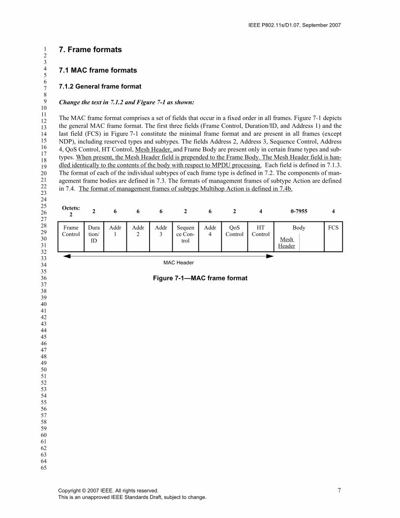
IEEE P802.11s/D1.07, September 2007
123456789
1011121314151617181920212223242526272829303132333435363738394041424344454647484950515253545556575859606162636465
7. Frame formats
7.1 MAC frame formats
7.1.2 General frame format
Change the text in 7.1.2 and Figure 7-1 as shown:
The MAC frame format comprises a set of fields that occur in a fixed order in all frames. Figure 7-1 depictsthe general MAC frame format. The first three fields (Frame Control, Duration/ID, and Address 1) and thelast field (FCS) in Figure 7-1 constitute the minimal frame format and are present in all frames (exceptNDP), including reserved types and subtypes. The fields Address 2, Address 3, Sequence Control, Address4, QoS Control, HT Control, Mesh Header, and Frame Body are present only in certain frame types and sub-types. When present, the Mesh Header field is prepended to the Frame Body. The Mesh Header field is han-dled identically to the contents of the body with respect to MPDU processing. Each field is defined in 7.1.3.The format of each of the individual subtypes of each frame type is defined in 7.2. The components of man-agement frame bodies are defined in 7.3. The formats of management frames of subtype Action are definedin 7.4. The format of management frames of subtype Multihop Action is defined in 7.4b.
Octets: 2 2 6 6 6 2 6 2 4 0-7955 4
Frame Control
Duration/ ID
Addr 1
Addr 2
Addr 3
Sequence Con-
trol
Addr 4
QoS Control
HT Control
Body FCS
Mesh Header
MAC Header
Figure 7-1—MAC frame format
Copyright © 2007 IEEE. All rights reserved. 7This is an unapproved IEEE Standards Draft, subject to change.

IEEE P802.11s/D1.07, September 2007
123456789
1011121314151617181920212223242526272829303132333435363738394041424344454647484950515253545556575859606162636465
7.1.3 Frame fields
7.1.3.1 Frame control field
7.1.3.1.2 Type and subtype fields
Change the contents of Table 7-1 as shown:
EDITORIAL NOTE—This subtype value needs to be allocated before sponsor ballot by ANA.
7.1.3.1.3 To DS and From DS fields
Change the contents of Table 7-2 as shown:
7.1.3.1.6 Power Management field
Change the contents of 7.1.3.1.6 as shown:
The Power Management field is 1 bit in length and is used to indicate the power management mode of aSTA. The value of this field remains constant in each frame from a particular STA within a frame exchangesequence defined in 9.12. In the case of STA in a BSS, tThe value indicates the mode in which the stationwill be after the successful completion of the frame exchange sequence. In the case of MP in a Mesh, thevalue indicates the mode in which the MP will be after the successful completion of the frame exchangesequence with all of its peer MPs.
A value of 1 indicates that the STA or MP will be in PS mode. A value of 0 indicates that the STA or MPwill be in active mode. This field is always set to 0 in frames transmitted by an AP.
7.1.3.1.8 More Data field
Insert the following text to the end of 7.1.3.1.8
Table 7-1—Valid type and subtype combinations
Type valueb3 b2 Type description Subtype value
b7 b6 b5 b4 Subtype description
00 Management <ANA 1> 1111 Multihop Action Reserved
Table 7-2—To/From DS combinations in data frames
To DS and From DS values Meaning
To DS = 1 From DS = 1
A data frame using the four-address MAC header format, including but not limited to mesh data frames. This standard does not define procedures for using this combination of field values.
8 Copyright © 2007 IEEE. All rights reserved.This is an unapproved IEEE Standards Draft, subject to change.

IEEE P802.11s/D1.07, September 2007
123456789
1011121314151617181920212223242526272829303132333435363738394041424344454647484950515253545556575859606162636465
Special considerations exist within a mesh. The ‘more data’ bit is set to 1 by MPs for individually addressedMSDU/MMPDUs sent to a neighboring MP when there are more frames to be transmitted to that MP in thetransmitter’s current beacon interval. The ‘more data’ bit is set to 1 by MPs for group addressed MSDUs/MMPDUs when there are more group addressed frames to be transmitted in the transmitter’s current beaconinterval.
Insert the following new clause after 7.1.3.5:
7.1.3.5a Mesh Header field
7.1.3.5a.1 General
The mesh header field is a 5to 23 octet field that includes:— an 8-bit Mesh Flags field to control mesh header processing — a time to live field for use in multi-hop forwarding to aid in limiting the effect of transitory path
selection loops— a mesh sequence number to suppress duplicates in broadcast/multicast forwarding and for other ser-
vices— and in some cases a 6, 12, or 18-octet mesh address extension field containing extended addresses
enabling up to a total of 6 addresses in mesh frames
The Mesh Header field, shown in Figure s4, is present in Data frames if and only if they are transmittedbetween peer MPs with an established peer link. Data frames including the Mesh Header field are referred toas Mesh Data frames. The Mesh Header is also included in Management frames of subtype MultihopAction.
7.1.3.5a.2 Mesh Flags field
The Mesh Flags field, shown in Figure s5, is 8 bits in length and the flags therein are used to control mesh-specific header processing, e.g., for mesh address extension.
The Address Extension (AE) Mode field is used to indicate the contents of the Mesh Address Extensionfield. Table s2 defines valid values for the Address Extension Mode and describes the corresponding con-
Octets: 1 1 3 0, 6, 12, or 18
Mesh Flags Mesh Time To Live (TTL)
Mesh Sequence Number
Mesh Address Extension (present in some con-figurations)
Figure s4—Mesh Header field
B0 B1 B2 B7
Address Extension (AE) Mode Reserved
Bits: 2 6
Figure s5—Mesh Flags field
Copyright © 2007 IEEE. All rights reserved. 9This is an unapproved IEEE Standards Draft, subject to change.

IEEE P802.11s/D1.07, September 2007
123456789
1011121314151617181920212223242526272829303132333435363738394041424344454647484950515253545556575859606162636465
tents of the Mesh Address Extension field (see 11A.5.5 for the usage of the optional addresses contained inthe Mesh Address Extension field). If the Address Extension Mode is set to 00, the Mesh Address Extensionfield is not present. For all other values, the Mesh Address Extension field follows the Mesh SequenceNumber field.
The reserved field is set to zero.
7.1.3.5a.3 Mesh Time to Live field
he Mesh Time to Live (TTL) field is an unsigned integer 8 bits in length corresponding to the remainingnumber of hops the frame may be forwarded. It is used to mitigate the impact of transient loops in a meshnetwork by ensuring frames that are caught in a loop are eventually discarded. See 11A.5.5.2 Addressingand Forwarding of Unicast Frames and 11A.5.5.3 Addressing and Forwarding of Broadcast Frames fordetails on how TTL is used in both individually and group addressed frames.
7.1.3.5a.4 Mesh Sequence Number field
The Mesh Sequence Number field is an unsigned integer 24 bits in length and used to detect duplicate recep-tion of messages in a Mesh network. See 11A.5.5.3 for details on how the Mesh Sequence Number is usedto discard duplicate frames.
Note: it is believed that a 24 bit sequence number is sufficient as the rollover would occur after a period of 28 minutesassuming a source transmission rate of 104 packets per second.
7.1.3.5a.5 Mesh Address Extension field
The Mesh Address Extension field, shown in Figure s6, is 6, 12, or 18 octets in length and follows the MeshSequence Number field only when the Address Extension Mode subfield of the Mesh Flags field is set to anon-zero value. The Mesh Address Extension field provides up to three additional address fields for meshaddress extension as defined in Table s2.
Address 4 is used in Management frames of subtype Multihop Action to add a fourth address (which is miss-ing from the MAC header of Management frames). Address 4 is not included in the Mesh Address Exten-sion field of Data frames.
Table s2—Valid values for the Address Extension Mode
Address Extension
Mode value (binary)
Address Extension Mode descriptionMesh Address Extension field length (octets)
Applicable frame types
00 No Mesh Address Extension field 0 Data
01 Mesh Address Extension field contains Addr4
6 Management (Multihop Action)
10 Mesh Address Extension field contains Addr5 and Addr6
12 Data
11 Mesh Address Extension field contains Addr4, Addr5, and Addr6
18 Management (Multihop Action)
10 Copyright © 2007 IEEE. All rights reserved.This is an unapproved IEEE Standards Draft, subject to change.

IEEE P802.11s/D1.07, September 2007
123456789
1011121314151617181920212223242526272829303132333435363738394041424344454647484950515253545556575859606162636465
Address 5 and Address 6 may be used to transport the addresses of source and destination end points in caseswhere either (or both) of the end points are not MPs at the beginning or end of a single mesh path. This isuseful, for example, in the following cases:
— When the end points of IEEE 802 communication are non-mesh, proxied entities which communi-cate over a mesh via proxy MPs.
— When the end points are MPs communicating with each other via a root MP in HWMP proactive treebuilding mode, where two distinct mesh paths are used (the first path being from the source MP tothe root MP and the second path being from the root MP to the destination MP).
Details on the usage of these optional address fields are given in 11A.5.5 as part of the description of frameaddressing and forwarding in a mesh network.
7.1.3.6 Frame Body field
Change the text of Clause 7.1.3.6 as shown:
The Frame Body is a variable length field that contains information specific to individual frame types andsubtypes. The minimum frame body is 0 octets. The maximum length frame body is defined by the maxi-mum length (MSDU + Mesh Header + ICV + IV), where the Mesh Header is defined in 7.1.3.5a and integ-rity check value (ICV) and initialization vector (IV) are the WEP fields defined in 8.2.1.
7.2 Format of individual frame types
7.2.1.4 PS-Poll frame format
Change the second paragraph in 7.2.1.4 as shown:
When the frame is transmitted by a STA in a BSS, tThe BSSID is the address of the STA contained in theAP. When the frame is transmitted by an MP in a mesh, the BSSID field is simply interpreted as RA. TheTA field is the address of the STA transmitting the frame. When the frame is transmitted by a STA in a BSS,tThe AID is the value assigned to the STA transmitting the frame by the AP in the association responseframe that established that STA’s current association. When the frame is transmitted by an MP in a mesh,the AID is the value assigned to the power saving MP (MP which operates in power save mode) transmittingthe frame by the power save supporting MP (MP which supports power save service) in the peer link con-firm frame that established that MP’s current peer link.
7.2.3 Management frames
Change the text of Clause 7.2.3 and Figure Figure 7-18— as shown:
The frame format for a management frame is independent of frame subtype and is defined in Figure Figure7-18—.
A STA uses the contents of the Address 1 (DARA) field to perform the address matching for receive deci-sions. In the case where the Address 1 (DARA) field contains a group address and the frame type is otherthan Beacon, if the STA is a member of a BSS or IBSS the Address 3 (BSSID) field also is validated to
Octets: 6 6 6
Address 4 Address 5 Address 6
Figure s6—Mesh Address Extension field
Copyright © 2007 IEEE. All rights reserved. 11This is an unapproved IEEE Standards Draft, subject to change.

IEEE P802.11s/D1.07, September 2007
123456789
1011121314151617181920212223242526272829303132333435363738394041424344454647484950515253545556575859606162636465
ensure that the broadcast or multicast originated from a STA in the BSS of which the receiving STA is amember. If the frame type is Beacon, other address matching rules apply, as specified in 11.1.2.3. Frames oftype Probe Request with a group address in the Address 1 field are processed as described in 11.1.3.2.1.
The address fields for all management frames do not vary by frame subtype subtypes except MultihopAction are as follows.
The Address 3 (BSSID) field of the management frame is determined as follows:a) If the STA is an AP or is associated with an AP, the BSSID is the address currently in use by the
STA contained in the AP.b) If the STA is a member of an IBSS, the BSSID is the BSSID of the IBSS.c) In management frames of subtype Probe Request, the BSSID is either a specific BSSID, or the wild-
card BSSID as defined in the procedures specified in 11.1.3.d) For single-hop management frames transmitted by MPs, the BSSID field is not used and should be
set to 0.
The Address 1 (RA=DA) field is the destination of the frame.
The Address 2 (TA=SA) field is the address of the STA transmitting the frame.
The address fields for the management frame subtype Multihop Action are as follows.
The Address 1 (RA) field is the receiver of the frame.
The Address 2 (TA) field is the transmitter of the frame.
The Address 3 (DA) field is the destination of the frame.
Octets: 2 2 6 6 6 2 0-2312 4
FrameControl
Duration/ID
Address1 (DA)
Address2 (SA)
Address3 BSSID
SequenceControl
Body FCS
MAC Header
Figure 7-18—Management frame format
12 Copyright © 2007 IEEE. All rights reserved.This is an unapproved IEEE Standards Draft, subject to change.

IEEE P802.11s/D1.07, September 2007
123456789
1011121314151617181920212223242526272829303132333435363738394041424344454647484950515253545556575859606162636465
7.2.3.1 Beacon frame format
Change the contents of the of Table 7-8-Beacon frame body as follows:
Insert the following additional rows (preserving their order) in Table 7-8-Beacon frame body just before the Vendor Specific information element and insert contiguous numbering in the “Order” column:
Change the title of 7.2.3.2 as shown:
7.2.3.3 IBSS ATIM frame format
7.2.3.4 Probe Request frame format
Insert the following additional rows (preserving their order) in before the last row of Table 7-14-Probe Request frame body just before the Vendor Specific information element and insert contiguous numbering in the “Order” column:
Table 7-8—Beacon frame body
Order Information Notes
4 Service Set Identifier (SSID)
When dot11MeshEnabled is true and the interface on which the beacon is being sent is not configured as an Access Point, the SSID information element is set to the wildcard value.
Order Information Notes
Mesh ID The Mesh ID information element may be present within Beacon frames when dot11MeshEnabled is true.
Mesh Configuration
The Mesh Configuration information element may be present within Beacon frames when dot11MeshEnabled is true.
Mesh Neighbor List
The Mesh Neighbor List information element may be present within frames with the DTIM bit set when both dot11MeshEnabled is true and the MP transmits to other MPs in power save mode.
Mesh TIM The Mesh TIM element may be present in Beacon frames generated by the MP when dot11MeshEnabled is true and MP is supporting Transmission to MP in power save mode.
Mesh ATIM Window
The Mesh ATIM window parameter element may be present only when dot11MeshEnabled is true and the MP intends to operate in power save mode.
Beacon Timing The Beacon Timing information element may be present within Beacon frames when dot11MeshEnabled is true.
MDAOP Advertisements
The MDAOP Advertisements information element may be present within Beacon frames when dot11MeshEnabled is true and the MP supports MDA.
MSCIE The MSCIE element may be present when dot11MeshEnabled is true.
Copyright © 2007 IEEE. All rights reserved. 13This is an unapproved IEEE Standards Draft, subject to change.

IEEE P802.11s/D1.07, September 2007
123456789
1011121314151617181920212223242526272829303132333435363738394041424344454647484950515253545556575859606162636465
7.2.3.5 Probe Response frame format
Insert the following additional rows (preserving their order) in before the last row of Table 7-15-Probe Response frame body just before the Vendor Specific information element and insert contiguous numbering in the “Order” column:
Insert the following new clause after 7.2.3.12:
7.2.3.13 Multihop Action Frame format
The frame body of a management frame of subtype Multihop Action contains the information shown inTable s3.
Table 7-14—Probe Request frame body
Order Information Notes
Mesh ID The Mesh ID information element may be present within Probe Request frames when dot11MeshEnabled is true.
Table 7-15—Probe Response frame body
Order Information Notes
Mesh ID The Mesh ID information element may be present within Probe Response frames when dot11MeshEnabled is true.
Mesh Configuration The Mesh Configuration information element may be present within Probe Response frames when dot11MeshEnabled is true.
Mesh Neighbor List The Mesh Neighbor List information element may be present within frames with the DTIM bit set when both dot11MeshEnabled is true and the MP transmits to other MPs in power save mode.
Mesh TIM The Mesh TIM element may be present within Probe Response frames only when both dot11MeshEnabled is true and MP supports Power Save mode.
Mesh ATIM Window The Mesh ATIM window parameter element may be present only when both dot11MeshEnabled is true and the MP intends to operate in power save mode.
Beacon Timing The Beacon Timing information element may be present within Probe Response frames when dot11MeshEnabled is true.
MDAOP Advertisements
The MDAOP Advertisements information element may be present within Beacon frames when dot11MeshEnabled is true and the MP supports MDA.
MSCIE The MSCIE element may be present when dot11MeshEnabled is true.
Table s3—Multihop Action frame body
Order Information
14 Copyright © 2007 IEEE. All rights reserved.This is an unapproved IEEE Standards Draft, subject to change.

IEEE P802.11s/D1.07, September 2007
123456789
1011121314151617181920212223242526272829303132333435363738394041424344454647484950515253545556575859606162636465
7.3 Management frame body components
7.3.1 Fields that are not information elements
7.3.1.4 Capability Information field
Change the fourth paragraph of 7.3.1.4 “Capability Information field” as shown:
APs set the ESS subfield to 1 and the IBSS subfield to 0 within transmitted Beacon or Probe Response man-agement frames. STAs within an IBSS set the ESS subfield to 0 and the IBSS subfield to 1 in transmittedBeacon or Probe Response management frames. MPs set the ESS and IBSS subfields to 0 in transmittedBeacon and Probe Response management frames.
1 Mesh Header
2 Action
Last One or more vendor-specific information ele-ments may appear in this frame. This informa-tion element follows all other information elements.
Table s3—Multihop Action frame body
Copyright © 2007 IEEE. All rights reserved. 15This is an unapproved IEEE Standards Draft, subject to change.

IEEE P802.11s/D1.07, September 2007
123456789
1011121314151617181920212223242526272829303132333435363738394041424344454647484950515253545556575859606162636465
7.3.1.7 Reason Code field
Insert the following rows into Table 7-22 and change the last row (Reserved) as shown.
EDITORIAL NOTE—The Mesh reason codes need to be allocated before sponsor ballot by ANA.
7.3.1.8 AID field
Change the text in Clause 7.3.1.8 as shown:
The In case of BSS operation, the AID field is a value assigned by an AP during association that representsthe 16-bit ID of a STA. In mesh operation, the AID field is a value assigned by an MP during peerlink estab-lishment that represents the 16-bit ID of a neighboring MP. The length of the AID field is 2 octets. The AIDfield is illustrated in Figure 7-26.
Table 7-22—Reason codes
Reason code Meaning
<ANA 2> “MESH-LINK-CANCELLED”. IEEE 802.11 SME cancels the link instance with the reason other than reaching the maximum number of neighbors
<ANA 3> “MESH-MAX-NEIGHBORS”. The Mesh Point has reached the supported maximum number of neighbors
<ANA 4> “MESH-CAPABILITY-POLICY-VIOLATION”. The received information violates the Mesh Configuration policy configured in the Mesh Point profile
<ANA 5> “MESH-CLOSE-RCVD”. The Mesh Point has received a Peer Link Close message requesting to close the peer link.
<ANA 6> “MESH-MAX-RETRIES”. The Mesh Point has re-sent dot11MeshMaxRetries Peer Link Open messages, without receiving a Peer Link Confirm message.
<ANA 7> “MESH-CONFIRM-TIMEOUT”. The confirmTimer for the mesh peer link instance times out.
<ANA 8> “MESH-SECURITY-ROLE-NEGOTIATION-DIFFERS”. The Mesh Point uses a different method for Role Negotiation, preventing MSA authentication from completing.
<ANA 9> “MESH-SECURITY-AUTHENTICATION-IMPOSSIBLE”. No common PMK-MA exists, and Initial MSA Authentication is also impossible, since no connection to the MKD exists.
<ANA 10> “MESH-SECURITY-FAILED-VERIFICATION”. The security-related information received in the peer link management message does not match the expected values.
<ANA 11> “MESH-INVALID-GTK”. The Mesh Point fails to unwrap the GTK or the values in the wrapped contents do not match
<ANA 12> “MESH-MISMATCH-GTK”. The MP that sends the GTK fails to verify that the same value is received by the peer
<ANA 13> “MESH-INCONSISTENT-PARAMETERS”. The Mesh Point receives inconsistent information about the mesh paramters between Peer Link Management frames
4655-65 535 Reserved
16 Copyright © 2007 IEEE. All rights reserved.This is an unapproved IEEE Standards Draft, subject to change.

IEEE P802.11s/D1.07, September 2007
123456789
1011121314151617181920212223242526272829303132333435363738394041424344454647484950515253545556575859606162636465
7.3.1.9 Status Code field
Insert the following rows into Table 7-23 and change the last row (Reserved) as shown.
EDITORIAL NOTE—The Mesh status codes need to be allocated before sponsor ballot by ANA.
Table 7-23—Status codes
Reason code Meaning
<ANA 14> “MESH-LINK-ESTABLISHED”. The mesh peer link has been successfully established
<ANA 15> “MESH-LINK-CLOSED”. The mesh peer link has been closed completely
<ANA 16> No listed Key Holder Transport type is supported.
<ANA 17> The Mesh Key Holder Security Handshake message was malformed.
<ANA 18> “MESH-LINK-MAX-RETRIES”. The MSA Abbreviated Handshake fails because no response after maximal number of retries.
<ANA 19> “MESH-LINK-NO-PMK”. The Abbreviated Handshake fails because no shared PMK
<ANA 20> “MESH-LINK-ALT-PMK”. The Abbreviated Handshake fails because no matching chosen PMK, but there exits an alternative choice.
<ANA 21> “MESH-LINK-NO-AKM”. The Abbreviated Handshake fails because no commonly supported AKM suite for Abbreviated Handshake exists.
<ANA 22> “MESH-LINK-ALT-AKM”. The Abbreviated Handshake fails because no matching chosen AKM, but there exists an alternative choice.
<ANA 23> “MESH-LINK-NO-KDF”. The Abbreviated Handshake fails because no supported KDF. The peer supports a different KDF.
<ANA 24> “MESH-LINK-MAX-RETRIES”. The MSA Abbreviated Handshake fails because no response after maximal number of retries.
<ANA 25> “MESH-LINK-NO-PMK”. The Abbreviated Handshake fails because no shared PMK
<ANA 26> “MESH-LINK-ALT-PMK”. The Abbreviated Handshake fails because no matching chosen PMK, but there exits an alternative choice.
<ANA 27> “MESH-LINK-NO-AKM”. The Abbreviated Handshake fails because no commonly supported AKM suite for Abbreviated Handshake exists.
<ANA 28> “MESH-LINK-ALT-AKM”. The Abbreviated Handshake fails because no matching chosen AKM, but there exists an alternative choice.
<ANA 29> “MESH-LINK-NO-KDF”. The Abbreviated Handshake fails because no supported KDF. The peer supports a different KDF.
5559-65 535 Reserved
Copyright © 2007 IEEE. All rights reserved. 17This is an unapproved IEEE Standards Draft, subject to change.
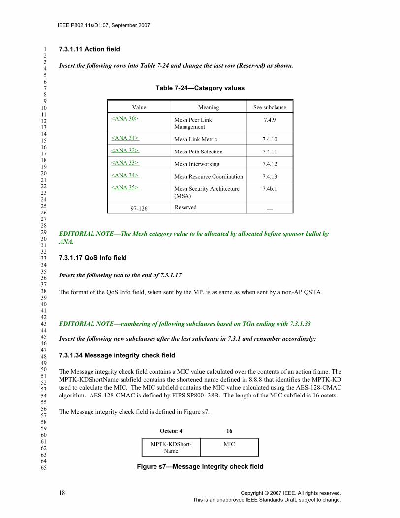
IEEE P802.11s/D1.07, September 2007
123456789
1011121314151617181920212223242526272829303132333435363738394041424344454647484950515253545556575859606162636465
7.3.1.11 Action field
Insert the following rows into Table 7-24 and change the last row (Reserved) as shown.
EDITORIAL NOTE—The Mesh category value to be allocated by allocated before sponsor ballot by ANA.
7.3.1.17 QoS Info field
Insert the following text to the end of 7.3.1.17
The format of the QoS Info field, when sent by the MP, is as same as when sent by a non-AP QSTA.
EDITORIAL NOTE—numbering of following subclauses based on TGn ending with 7.3.1.33
Insert the following new subclauses after the last subclause in 7.3.1 and renumber accordingly:
7.3.1.34 Message integrity check field
The Message integrity check field contains a MIC value calculated over the contents of an action frame. TheMPTK-KDShortName subfield contains the shortened name defined in 8.8.8 that identifies the MPTK-KDused to calculate the MIC. The MIC subfield contains the MIC value calculated using the AES-128-CMACalgorithm. AES-128-CMAC is defined by FIPS SP800- 38B. The length of the MIC subfield is 16 octets.
The Message integrity check field is defined in Figure s7.
Table 7-24—Category values
Value Meaning See subclause
<ANA 30> Mesh Peer Link Management
7.4.9
<ANA 31> Mesh Link Metric 7.4.10
<ANA 32> Mesh Path Selection 7.4.11
<ANA 33> Mesh Interworking 7.4.12
<ANA 34> Mesh Resource Coordination 7.4.13
<ANA 35> Mesh Security Architecture (MSA)
7.4b.1
97-126 Reserved ---
Octets: 4 16
MPTK-KDShort-Name
MIC
Figure s7—Message integrity check field
18 Copyright © 2007 IEEE. All rights reserved.This is an unapproved IEEE Standards Draft, subject to change.
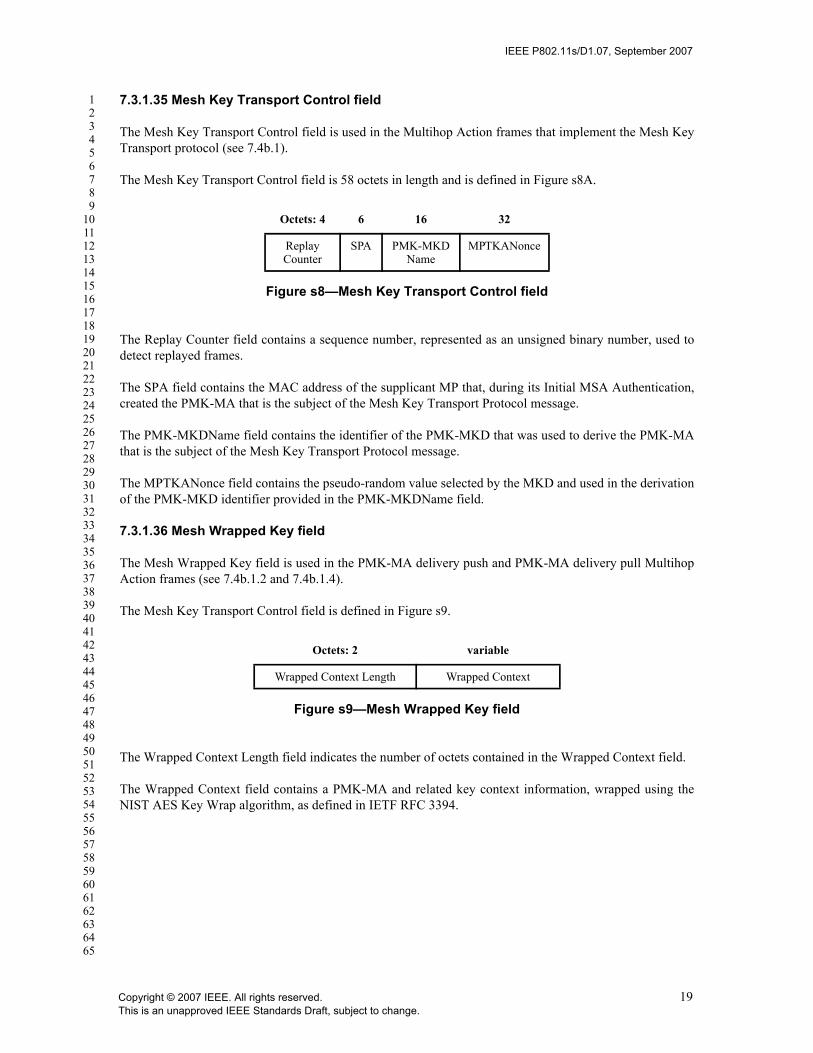
IEEE P802.11s/D1.07, September 2007
123456789
1011121314151617181920212223242526272829303132333435363738394041424344454647484950515253545556575859606162636465
7.3.1.35 Mesh Key Transport Control field
The Mesh Key Transport Control field is used in the Multihop Action frames that implement the Mesh KeyTransport protocol (see 7.4b.1).
The Mesh Key Transport Control field is 58 octets in length and is defined in Figure s8A.
The Replay Counter field contains a sequence number, represented as an unsigned binary number, used todetect replayed frames.
The SPA field contains the MAC address of the supplicant MP that, during its Initial MSA Authentication,created the PMK-MA that is the subject of the Mesh Key Transport Protocol message.
The PMK-MKDName field contains the identifier of the PMK-MKD that was used to derive the PMK-MAthat is the subject of the Mesh Key Transport Protocol message.
The MPTKANonce field contains the pseudo-random value selected by the MKD and used in the derivationof the PMK-MKD identifier provided in the PMK-MKDName field.
7.3.1.36 Mesh Wrapped Key field
The Mesh Wrapped Key field is used in the PMK-MA delivery push and PMK-MA delivery pull MultihopAction frames (see 7.4b.1.2 and 7.4b.1.4).
The Mesh Key Transport Control field is defined in Figure s9.
The Wrapped Context Length field indicates the number of octets contained in the Wrapped Context field.
The Wrapped Context field contains a PMK-MA and related key context information, wrapped using theNIST AES Key Wrap algorithm, as defined in IETF RFC 3394.
Octets: 4 6 16 32
Replay Counter
SPA PMK-MKDName
MPTKANonce
Figure s8—Mesh Key Transport Control field
Octets: 2 variable
Wrapped Context Length Wrapped Context
Figure s9—Mesh Wrapped Key field
Copyright © 2007 IEEE. All rights reserved. 19This is an unapproved IEEE Standards Draft, subject to change.
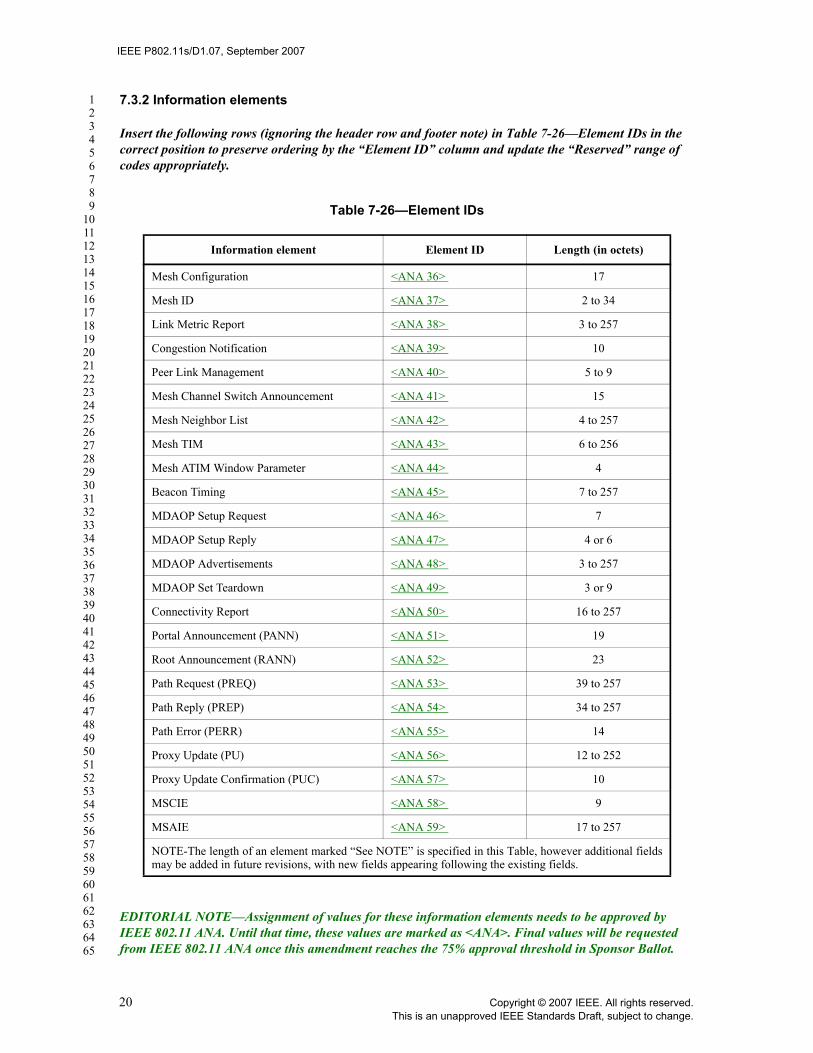
IEEE P802.11s/D1.07, September 2007
123456789
1011121314151617181920212223242526272829303132333435363738394041424344454647484950515253545556575859606162636465
7.3.2 Information elements
Insert the following rows (ignoring the header row and footer note) in Table 7-26—Element IDs in the correct position to preserve ordering by the “Element ID” column and update the “Reserved” range of codes appropriately.
EDITORIAL NOTE—Assignment of values for these information elements needs to be approved by IEEE 802.11 ANA. Until that time, these values are marked as <ANA>. Final values will be requested from IEEE 802.11 ANA once this amendment reaches the 75% approval threshold in Sponsor Ballot.
Table 7-26—Element IDs
Information element Element ID Length (in octets)
Mesh Configuration <ANA 36> 17
Mesh ID <ANA 37> 2 to 34
Link Metric Report <ANA 38> 3 to 257
Congestion Notification <ANA 39> 10
Peer Link Management <ANA 40> 5 to 9
Mesh Channel Switch Announcement <ANA 41> 15
Mesh Neighbor List <ANA 42> 4 to 257
Mesh TIM <ANA 43> 6 to 256
Mesh ATIM Window Parameter <ANA 44> 4
Beacon Timing <ANA 45> 7 to 257
MDAOP Setup Request <ANA 46> 7
MDAOP Setup Reply <ANA 47> 4 or 6
MDAOP Advertisements <ANA 48> 3 to 257
MDAOP Set Teardown <ANA 49> 3 or 9
Connectivity Report <ANA 50> 16 to 257
Portal Announcement (PANN) <ANA 51> 19
Root Announcement (RANN) <ANA 52> 23
Path Request (PREQ) <ANA 53> 39 to 257
Path Reply (PREP) <ANA 54> 34 to 257
Path Error (PERR) <ANA 55> 14
Proxy Update (PU) <ANA 56> 12 to 252
Proxy Update Confirmation (PUC) <ANA 57> 10
MSCIE <ANA 58> 9
MSAIE <ANA 59> 17 to 257
NOTE-The length of an element marked “See NOTE” is specified in this Table, however additional fieldsmay be added in future revisions, with new fields appearing following the existing fields.
20 Copyright © 2007 IEEE. All rights reserved.This is an unapproved IEEE Standards Draft, subject to change.

IEEE P802.11s/D1.07, September 2007
123456789
1011121314151617181920212223242526272829303132333435363738394041424344454647484950515253545556575859606162636465
EDITORIAL NOTE—The length stored in Table 7-26 specifies the length of the Information field, including 1 octet Element ID and 1 octet Length, in addition to the information specific to the element. Thus, the length shown in this table should be 2-octets larger than the length value that is encoded in an information element, which only specifies the length of the information contained in the element. The valid range for the length values in Table 7-26 is 2-257 octets (corresponding to elements with 0-255 octet information length).
7.3.2.1 SSID element
Change the second paragraph of 7.3.2.1 as shown:
The length of the SSID information field is between 0 and 32 octets. A 0 length information field is usedwithin Probe Request management frames to indicate the wildcard SSID. The wildcard SSID is also used inBeacon management frames transmitted by MPs.
7.3.2.25 RSN information element
Insert a column in Figure Figure 7-72— as shown below.
Figure 7-72—RSN information element format
Element ID
Length Version Group Cipher Suite
Pairwise Cipher Suite Count
Pairwise Cipher Suite List
AKM Suite Count
AKM Suite List
RSN Capabilities
PMKID Count
PMKID List
KDF
Octets: 1
1 2 4 2 4-m 2 4-n 2 2 16-s 4
Copyright © 2007 IEEE. All rights reserved. 21This is an unapproved IEEE Standards Draft, subject to change.
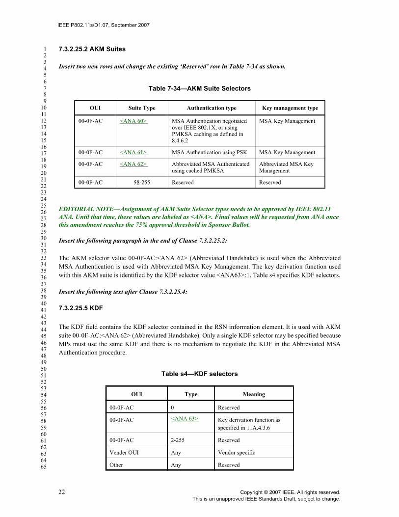
IEEE P802.11s/D1.07, September 2007
123456789
1011121314151617181920212223242526272829303132333435363738394041424344454647484950515253545556575859606162636465
7.3.2.25.2 AKM Suites
Insert two new rows and change the existing ‘Reserved’ row in Table 7-34 as shown.
EDITORIAL NOTE—Assignment of AKM Suite Selector types needs to be approved by IEEE 802.11 ANA. Until that time, these values are labeled as <ANA>. Final values will be requested from ANA once this amendment reaches the 75% approval threshold in Sponsor Ballot.
Insert the following paragraph in the end of Clause 7.3.2.25.2:
The AKM selector value 00-0F-AC:<ANA 62> (Abbreviated Handshake) is used when the AbbreviatedMSA Authentication is used with Abbreviated MSA Key Management. The key derivation function usedwith this AKM suite is identified by the KDF selector value <ANA63>:1. Table s4 specifies KDF selectors.
Insert the following text after Clause 7.3.2.25.4:
7.3.2.25.5 KDF
The KDF field contains the KDF selector contained in the RSN information element. It is used with AKMsuite 00-0F-AC:<ANA 62> (Abbreviated Handshake). Only a single KDF selector may be specified becauseMPs must use the same KDF and there is no mechanism to negotiate the KDF in the Abbreviated MSAAuthentication procedure.
Table 7-34—AKM Suite Selectors
OUI Suite Type Authentication type Key management type
00-0F-AC <ANA 60> MSA Authentication negotiated over IEEE 802.1X, or using PMKSA caching as defined in 8.4.6.2
MSA Key Management
00-0F-AC <ANA 61> MSA Authentication using PSK MSA Key Management
00-0F-AC <ANA 62> Abbreviated MSA Authenticated using cached PMKSA
Abbreviated MSA Key Management
00-0F-AC 58-255 Reserved Reserved
Table s4—KDF selectors
OUI Type Meaning
00-0F-AC 0 Reserved
00-0F-AC <ANA 63> Key derivation function as specified in 11A.4.3.6
00-0F-AC 2-255 Reserved
Vender OUI Any Vendor specific
Other Any Reserved
22 Copyright © 2007 IEEE. All rights reserved.This is an unapproved IEEE Standards Draft, subject to change.

IEEE P802.11s/D1.07, September 2007
123456789
1011121314151617181920212223242526272829303132333435363738394041424344454647484950515253545556575859606162636465
7.3.2.29 EDCA Parameter Set element
Change the last paragraph of 7.3.2.29 as shown:
The default values used by non-AP STAs and MPs for the parameters in the EDCA Parameter Set elementare defined in Table 7-37.
Insert the following new subclauses after 7.3.2.52
EDITORIAL NOTE—numbering of following subclauses based on TGw ending with 7.3.2.53
7.3.2.54 Mesh Configuration element
The “Mesh Configuration” element shown in Figure s10 is used to advertise Mesh services. It is contained inBeacon frames transmitted by MPs, and is also contained in Peer Link Open and Peer Link Confirm frames.
The Element ID is set to the value given in Table 7-26 for this information element. The Length field is setto 15. The version is set to 1.
The remainder of the fields are described in the following subclauses.
7.3.2.54.1 Active Path Selection Protocol Identifier
MPs support one or more path selection protocols and one or more path metrics. However, only one pathselection protocol and one path metric may be active in a particular mesh network at a time. The Active PathSelection Protocol Identifier field indicates the path selection protocol that is currently used to generate pathselection information on an MP, as defined in 11A.5. The format of the Active Path Selection Protocol iden-tifier is shown in Figure s11. Path selection protocol identifier values are listed in Table s5.
Octets:1 1 1 4 4 4 4 2
ID Length Version Active Path SelectionProtocol Identifier
Active Path Selection Metric Iden-tifier
Congestion Control Mode Identi-fier
ChannelPrecedence
Mesh Capability
Figure s10—Mesh Configuration element
Octets: 3 1
OUI Path selection protocol identifier value
Figure s11—Active path selection protocol identifier field
Copyright © 2007 IEEE. All rights reserved. 23This is an unapproved IEEE Standards Draft, subject to change.

IEEE P802.11s/D1.07, September 2007
123456789
1011121314151617181920212223242526272829303132333435363738394041424344454647484950515253545556575859606162636465
A Null protocol indicates the MP has no active layer 2 path selection and forwarding. An MP with Null pro-tocol does not send or respond to path selection protocol messages.
7.3.2.54.2 Active Path Selection Metric Identifier
The Active Path Selection Metric Identifier field indicates the path metric that is currently used by the activepath selection protocol in the mesh network. The format of the Active Path Selection Metric Identifier isshown in Figure s12. Path selection metric identifier values are defined in Table s6.
The null metric is used in conjunction with null path selection protocol setting.
7.3.2.54.3 Congestion Control Mode Identifier
The Congestion Control Mode Identifier field indicates the congestion control protocol that is currently usedas defined in 11A.10. The format of the Congestion Control Mode Identifier is shown in Figure s13.
Congestion control mode identifier values are defined in Table s7.
A Null protocol indicates the MP has no active congestion control protocol.
Table s5—Path selection protocol identifier values
OUI Value Meaning
00-0F-AC 0 Hybrid Wireless Mesh Protocol (default path selection protocol)
00-0F-AC 1-254 Reserved for future use
00-0F-AC 255 Null protocol
Vendor OUI 0-255 Vendor specific
Octets: 3 1
OUI Path selection metric identifier value
Figure s12—Active path selection metric identifier field
Table s6—Path selection metric identifier values
OUI Value Meaning
00-0F-AC 0 Airtime link metric defined in 11A.7 (default path selection metric)
00-0F-AC 1-254 Reserved for future use
00-0F-AC 255 Null metric
Vendor OUI 0-255 Vendor specific
24 Copyright © 2007 IEEE. All rights reserved.This is an unapproved IEEE Standards Draft, subject to change.

IEEE P802.11s/D1.07, September 2007
123456789
1011121314151617181920212223242526272829303132333435363738394041424344454647484950515253545556575859606162636465
7.3.2.54.4 Channel Precedence
The channel precedence field is set to the value of channel precedence of the unified channel graph to whichthe MP PHY belongs. Usage of the channel precedence field is described in 11A.3. A value of 0 identifiesthat the MP PHY is not currently operating with the simple channel unification protocol.
7.3.2.54.5 Mesh Capability
The mesh capability field comprises a set of values indicating whether an MP is a possible candidate for peerlink establishment. The details of the mesh capability field are shown in Figure s14.
The “Accepting Peer Links” field is set to 1 if the MP is able and willing to establish peer links with otherMPs and set to 0 otherwise.
The “Power Save Support Enabled” field is set to 1 if the MP is a power save supporting MP and capable ofmaintaining peer links with MPs in Power Save mode and set to 0 otherwise.
The “Synchronization Enabled” field is set to 1 if the MP supports timing synchronization with peer MPsand is set to 0 otherwise.
The “Synchronization Active” field is set to 1 if the MP is currently a synchronizing MP and set to 0 other-wise.
Octets: 3 1
OUI Congestion control mode identifier value
Figure s13—Congestion control mode identifier field
Table s7—Congestion control mode identifier values
OUI Value Meaning
00-0F-AC 0 Default congestion control protocol
00-0F-AC 1-254 Reserved for future use
00-0F-AC 255 Null protocol
Vendor OUI 0-255 Vendor specific
B0 B1 B2 B3 B4 B5 B6 B7 B15
Accepting Peer Links
Power Save Sup-
port Enabled
Synchroniza-tion Enabled
Synchroniza-tion Active
Synchroniza-tion Support
Required from Peer
MDA Enabled
Forward-ing
Reserved
Bits: 1 1 1 1 1 1 1 9
Figure s14—Mesh Capability field
Copyright © 2007 IEEE. All rights reserved. 25This is an unapproved IEEE Standards Draft, subject to change.
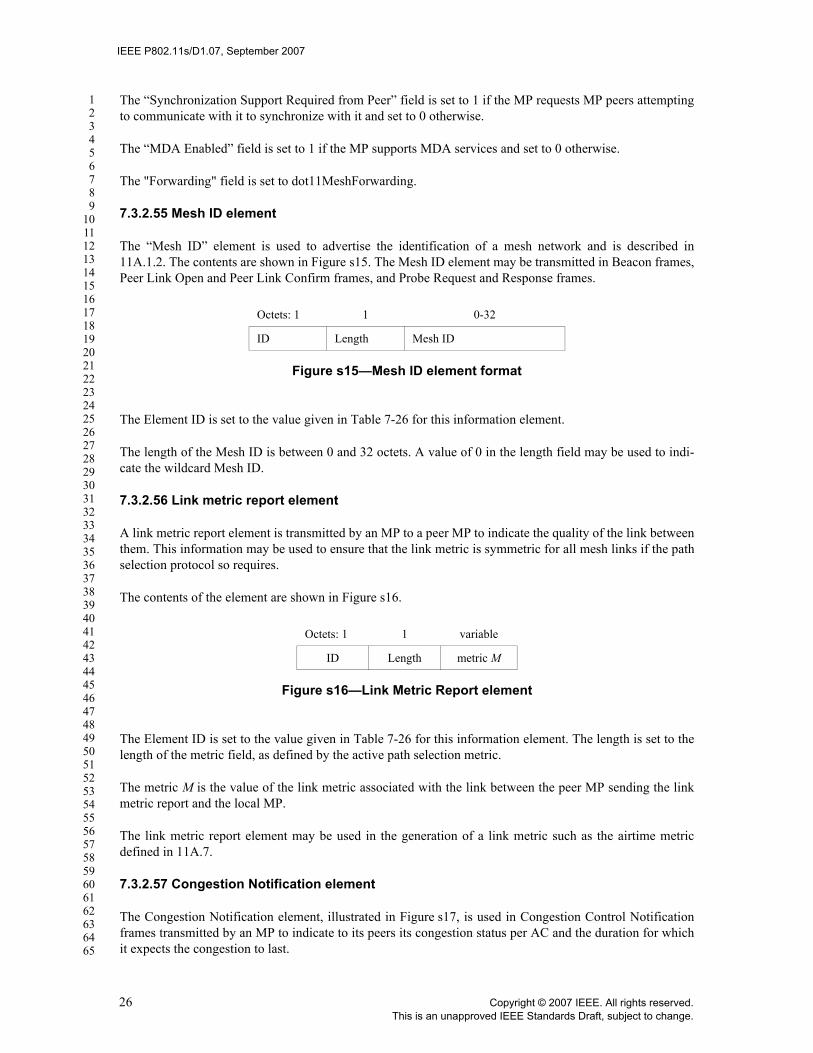
IEEE P802.11s/D1.07, September 2007
123456789
1011121314151617181920212223242526272829303132333435363738394041424344454647484950515253545556575859606162636465
The “Synchronization Support Required from Peer” field is set to 1 if the MP requests MP peers attemptingto communicate with it to synchronize with it and set to 0 otherwise.
The “MDA Enabled” field is set to 1 if the MP supports MDA services and set to 0 otherwise.
The "Forwarding" field is set to dot11MeshForwarding.
7.3.2.55 Mesh ID element
The “Mesh ID” element is used to advertise the identification of a mesh network and is described in11A.1.2. The contents are shown in Figure s15. The Mesh ID element may be transmitted in Beacon frames,Peer Link Open and Peer Link Confirm frames, and Probe Request and Response frames.
The Element ID is set to the value given in Table 7-26 for this information element.
The length of the Mesh ID is between 0 and 32 octets. A value of 0 in the length field may be used to indi-cate the wildcard Mesh ID.
7.3.2.56 Link metric report element
A link metric report element is transmitted by an MP to a peer MP to indicate the quality of the link betweenthem. This information may be used to ensure that the link metric is symmetric for all mesh links if the pathselection protocol so requires.
The contents of the element are shown in Figure s16.
The Element ID is set to the value given in Table 7-26 for this information element. The length is set to thelength of the metric field, as defined by the active path selection metric.
The metric M is the value of the link metric associated with the link between the peer MP sending the linkmetric report and the local MP.
The link metric report element may be used in the generation of a link metric such as the airtime metricdefined in 11A.7.
7.3.2.57 Congestion Notification element
The Congestion Notification element, illustrated in Figure s17, is used in Congestion Control Notificationframes transmitted by an MP to indicate to its peers its congestion status per AC and the duration for whichit expects the congestion to last.
Octets: 1 1 0-32
ID Length Mesh ID
Figure s15—Mesh ID element format
Octets: 1 1 variable
ID Length metric M
Figure s16—Link Metric Report element
26 Copyright © 2007 IEEE. All rights reserved.This is an unapproved IEEE Standards Draft, subject to change.

IEEE P802.11s/D1.07, September 2007
123456789
1011121314151617181920212223242526272829303132333435363738394041424344454647484950515253545556575859606162636465
The Element ID is set to the value given in Table 7-26 for this information element. The length is set to 8.
The element contains four Congestion Notification Expiration Timer fields for the four EDCA access cate-gories to indicate the estimated congestion duration per AC. The congestion notification expiration timervalues are encoded as unsigned integers in units of 0.1 TUs.
7.3.2.58 Peer Link Management element
The Peer Link Management element is transmitted by an MP to manage a peer link with a peer MP. The for-mat of the Peer Link Management element is shown in Figure s18.
The Element ID is set to the value given in Table 7-26 for this information element.
The Subtype field specifies the type of the Peer Link Management element. There are three subtypes: PeerLink Open (0), Peer Link Confirm (1), and Peer Link Close (2). The values 3—28-1 are reserved.
The Peer Link Management element with subtype 0 is referred to as Peer Link Open element. The Peer LinkManagement element with subtype 1 is referred to as Peer Link Confirm element. The Peer Link Manage-ment element with subtype 2 is referred to as Peer Link Close element.
The value of the Length field varies depending on the subtype of the Peer Link Management element. TheLength is 7 for Peer Link Close, 3 for Peer Link Open, and 5 for Peer Link Confirm.
The Local Link ID is the integer generated by the MP to identify the link instance. This field is present forall three types of Peer Link Management elements.
The Peer Link ID is the integer generated by the peer MP to identify the link instance. This field is notpresent for the Peer Link Open subtype, is present for the Peer Link Confirm subtype, and may be presentfor the Peer Link Close subtype.
The Reason Code field enumerates reasons for sending a Peer Link Close. It is present for the Peer LinkClose subtype and is not present for Peer Link Open or Peer Link Confirm subtypes. This field enumeratesthe following reasons:
— MESH-LINK-CANCELLED: IEEE 802.11 SME cancels the link instance.
— MESH-MAX-NEIGHBORS: The limit of maximum of neighbors is reached.
Octets: 1 1 2 2 2 2
ID Length Congestion Notifica-tion Expira-tion Timer (AC_BK)
Congestion Notifica-tion Expira-tion Timer (AC_BE)
Congestion Notifica-tion Expira-tion Timer (AC_VI)
Congestion Notifica-tion Expira-tion Timer (AC_VO)
Figure s17—Congestion Notification element format
Octets: 1 1 1 2 2 2
Element ID Length Subtype Local Link ID Peer Link ID Reason Code
Figure s18—Peer Link Management element
Copyright © 2007 IEEE. All rights reserved. 27This is an unapproved IEEE Standards Draft, subject to change.

IEEE P802.11s/D1.07, September 2007
123456789
1011121314151617181920212223242526272829303132333435363738394041424344454647484950515253545556575859606162636465
— MESH-CONFIGURATION-POLICY-VIOLATION: The received request violates the MP’s MeshConfiguration.
— MESH-CLOSE-RCVD: The MP has received a correct Peer Link Close message (according to crite-ria defined in 11A.2.2).
— MESH-MAX-RETRIES: The limit of dot11MeshMaxRetries is reached.— MESH-CONFIRM-TIMEOUT: The confirmTimer times out.
7.3.2.59 Mesh Channel Switch Announcement element
The Mesh Channel Switch Announcement element is used by an MP in a Mesh to advertise to other MPswhen it is changing to a new channel and the channel number and precedence value of the new channel (See11A.3.3). The format of the Mesh Channel Switch Announcement element is shown in Figure s19.
The Element ID is set to the value given in Table 7-26 for this information element. The length is set to 13octets.
The Channel Switch Mode field indicates restrictions on transmission until a channel switch. An MP sets theChannel Switch Mode field to either 0 or 1 on transmission. A Channel Switch Mode set to 1 means that theMP to which the frame containing the element is addressed is advised to transmit no further frames on thecurrent channel until the scheduled channel switch. A Channel Switch Mode set to 0 does not imposerequirement on the receiving MP. Values from 2 to 255 are reserved.
The New Channel Number field is set to the number of the channel to which the MP is moving.
The New Channel Precedence Indicator field is set to the channel precedence value of the channel to whichthe MP is moving. See 11A.3 for more information on the channel precedence indicator.
The Channel Switch Count field is set to the time in TUs (in the range from 0-255) until the MP sending theMesh Channel Switch Announcement element switches to the new channel.
The Source Address field is set to the address of the MP that originates the frame.
The Mesh Channel Switch Announcement element is included in Mesh Channel Switch Announcementframes.
7.3.2.60 Mesh Neighbor List element
The Mesh Neighbor List element is used by an MP to advertise its peer MPs and their Power ManagementMode. The element contains list of the MAC addresses of current peer MPs and information about theirPower Management Mode. The MP Control field contains the connectivity reporting control information.
Octets: 1 1 1 1 4 1 6
ID Length Channel Switch Mode
New Chan-nel Number
New Chan-nel Prece-
dence Indicator
Channel Switch Count
Source Address
Figure s19—Mesh Channel Switch Announcement element
28 Copyright © 2007 IEEE. All rights reserved.This is an unapproved IEEE Standards Draft, subject to change.

IEEE P802.11s/D1.07, September 2007
123456789
1011121314151617181920212223242526272829303132333435363738394041424344454647484950515253545556575859606162636465
The format of the Mesh Neighbor List element is shown in Figure s20.
The Element ID is set to the value given in Table 7-26 for this information element. The length is set to 1 to255 octets.
The format of the MP control field is shown in Figure s21.
The Connectivity Reporting Interval specifies an integer value of the mesh DTIM Beacon frames betweenthe Connectivity Report transmissions. Connectivity Reporting Interval set to zero indicates that connectiv-ity reporting is not used.
The Power management mode of reporting MP field indicates the beacon broadcaster’s power managementmode. If the Power management mode of reporting MP bit is set to 1, then the beacon broadcaster sends onlyBeacons sent with the Mesh DTIM count field in the Mesh TIM element set to 0. If the Power managementmode of reporting MP bit is set to 0, then the beacon broadcaster is in active mode.
The MAC addresses of the neighbors are set for the MPs that have established links to their peers, which arelisted in the Connectivity Reports received by the BB within dot11BBConnectivityReportTimeoutmesh DTIM intervals.
The neighbor operating in power save mode bitfield indicates the current power save mode of each neighborlist member. Each bit of this field indicates the power management mode of the corresponding neighbor listmember. If a bit is set to 0, then the corresponding neighbor list member is in “active mode” and if a bit is setto 1, the corresponding neighbor list member is in “Power Save mode”. For example, if the Mesh NeighborList element contains 8 MAC addresses and the neighbor operating in power save mode bitfield is‘00110001’, then the MPs with MAC addresses in positions 3, 4, and 8 in the neighbor list are in the powersave mode. The neighbor operating in power save mode bitfield length is zero-padded to an integer numberof octets. The bits are in the same order as the MAC addresses. The length of the neighbor operating inpower save mode field is the following number of octets: least integer greater than or equal to n divided by8.
Octets: 1 1 1 1 6 6 ... 6 ceiling(n/8)
ID Length MP con-trol
Neighbor Count
MAC Address of neigh-
bor 1
MAC Address of neigh-
bor 2
... MAC Address of neigh-
bor n
Neighbor operating in power save mode (bit-
field)
Figure s20—Mesh Neighbor List element
B1 B3 B4 B5 B6 B7
Connectivity Reporting Interval
Reserved Reserved Reserved Power man-agement mode of reporting MP
Bits: 4 1 1 1 1
Figure s21—MP Control field
Copyright © 2007 IEEE. All rights reserved. 29This is an unapproved IEEE Standards Draft, subject to change.

IEEE P802.11s/D1.07, September 2007
123456789
1011121314151617181920212223242526272829303132333435363738394041424344454647484950515253545556575859606162636465
7.3.2.61 Mesh TIM element
The Mesh TIM element contains four fields: Mesh DTIM count, Mesh DTIM period, Bitmap control, andPartial virtual bitmap. The field structure of the Mesh TIM element is the same as the TIM element.
The format of the Mesh TIM element is shown in Figure s22.
The Element ID is set to the value given in Table 7-26 for this information element. The length field indi-cates the length of this information element, which is constrained as described below.
The Mesh DTIM Count field indicates the number of Beacon frames (including the current frame) thatappear before the next Mesh DTIM. A Mesh DTIM count of 0 indicates that the current Mesh TIM is aMesh DTIM. The Mesh DTIM count field is a single octet.
The Mesh DTIM Period field indicates the number of Beacon intervals between successive Mesh DTIMs. Ifall Mesh TIMs are Mesh DTIMs, the Mesh DTIM Period has the value 1. The Mesh DTIM Period value 0 isreserved. The Mesh DTIM period field is a single octet.
The Bitmap Control field is a single octet. Bit 0 of the field contains the Traffic Indicator bit associated withAID 0. This bit is set to 1 in Mesh TIM elements with a value of 0 in the Mesh DTIM Count field when oneor more broadcast or multicast frames are buffered at the MP. The remaining 7 bits of the field form the Bit-map Offset.
The traffic-indication virtual bitmap, maintained by the MP that generates a Mesh TIM, consists of 2008bits, and is organized into 251 octets such that bit number N ( ) in the bitmap corresponds to bitnumber (N mod 8) in octet number N/8 where the low-order bit of each octet is bit number 0, and the highorder bit is bit number 7. Each bit in the traffic-indication virtual bitmap corresponds to traffic buffered for aspecific neighboring MP within the Mesh that the MP is prepared to deliver at the time the beacon frame istransmitted.
Bit number N is 0 if there are no directed frames buffered for the neighboring MP whose AID is N. If anydirected frames for that neighboring MP are buffered and the MP is prepared to deliver them, bit number Nin the traffic-indication virtual bitmap is 1.
The Partial Virtual Bitmap field consists of octets numbered N1 through N2 of the traffic indication virtualbitmap, where N1 is the largest even number such that bits numbered 1 through (N1 × 8) - 1 in the bitmapare all 0 and N2 is the smallest number such that bits numbered (N2 + 1) × 8 through 2007 in the bitmap areall 0. In this case, the Bitmap Offset subfield value contains the number N1/2, and the Length field is be setto (N2 - N1) + 4.
In the event that all bits other than bit 0 in the virtual bitmap are 0, the Partial Virtual Bitmap field isencoded as a single octet equal to 0, the Bitmap Offset subfield is 0, and the Length field is 4.
Octets: 1 1 1 1 1 1-251
ID Length Mesh DTIM Count
Mesh DTIM Period
Bitmap Control
Partial Vir-tual Bitmap
Figure s22—Mesh TIM element
0 N 2007≤ ≤
30 Copyright © 2007 IEEE. All rights reserved.This is an unapproved IEEE Standards Draft, subject to change.

IEEE P802.11s/D1.07, September 2007
123456789
1011121314151617181920212223242526272829303132333435363738394041424344454647484950515253545556575859606162636465
7.3.2.62 Mesh ATIM window parameter element
The Mesh ATIM window parameter element contains the Mesh ATIM Window parameter. It is present inBeacon and Probe Response frames when the MP is operating in power save mode or intends to operate inpower save mode.
The contents of the element are shown in Figure s23.
The Element ID is set to the value given in Table 7-26 for this information element. The length field is set to2.
The Mesh ATIM window field is 2 octets in length and contains the Mesh ATIM window length in TUs.
7.3.2.63 Beacon Timing element
The Beacon Timing element is used by a synchronizing MP to advertise an offset between its self TSF andthe Mesh TSF, and to advertise the beacon timing information of zero or more of its neighbors. The formatof the Beacon Timing element is shown in Figure s24.
The Element ID is set to the value given in Table 7-26 for this information element. The length is set to 5 to255 octets.
The format of the Self Beacon Timing field is shown in Figure s25.
Octets: 1 1 2
ID Length Mesh ATIM Window
Figure s23—Mesh ATIM window parameter element
Octets: 1
1 4 1 1 3 1 3 ...
ID Length Self Bea-con Timing
Number ofSynchro-nizing neighbors reported
Last byte of MAC Address of Synch MP 1
Synchro-nized Beacon TimingMP 1
Last byte of MAC Address of Synch MP 2
Synchro-nizedBeacon TimingMP 2
...
1 3 1 5 … 1 5
Last byte of MAC Address of Synch MP n
SynchBeacon TimingMP n
Last byte of MAC Address of Non-synch MP 1
Non-syn-chronized Beacon Timing non-synch MP 1
… Last byte of MAC Address of Non-synch MP m
Non-syn-chronized Beacon Timing non-synch MP m
Figure s24—Beacon Timing element
Copyright © 2007 IEEE. All rights reserved. 31This is an unapproved IEEE Standards Draft, subject to change.

IEEE P802.11s/D1.07, September 2007
123456789
1011121314151617181920212223242526272829303132333435363738394041424344454647484950515253545556575859606162636465
The ‘Self TBTT offset’ subfield of the Self Beacon timing field indicates the offset, measured in TUs, usedby the MP for its TSF time compared to the Mesh TSF. The sum of the MP TSF time stamp and the offsetequals the mesh TSF time.
The ‘MP’s Mesh DTIM period’ subfield of the Self Beacon timing field indicates the MP’s Mesh DTIMperiod of the specific MP (i.e., how many Beacon intervals of the MP compose a single Mesh DTIM inter-val).
The ‘Number of Synchronizing Neighbors Reported’ field specifies the number of synchronizing neighborswhose beacon timing information is reported following this field.
The beacon timing information of synchronizing neighbors is reported in terms of the last byte of MACaddress field and the ‘Synchronized Beacon Timing’ field that are included as pairs. The Beacon Timingelement may contain zero or more ‘Last byte of MAC Address of Synch MP’ and the ‘Synchronized BeaconTiming’ field pairs.
The Last Byte of MAC Address of Synch MP field indicates the last byte of the MAC address of neighborsthat have a non-zero Self TBTT offset value, whose information is reported in the value of the next ‘Syn-chronized Beacon Timing’ field. The Last Byte of MAC address need not be unique, as the relevant infor-mation is the timing information that follows it. The relevant information is the set of times when successfulBeacon frames are being received.
The format of the Synchronized Beacon Timing field is shown in Figure s26.
The ‘TBTT offset’ field is expressed in units of TU, and indicates the offset used by the neighboring MPsfor their TSF time stamps compared to the Mesh TSF. For those MPs reporting self TBTT offsets with ahigher resolution than a TU, the field is rounded to the nearest TU.
The ‘Time since last beacon’ field indicates the time passed measured in units of Mesh DTIM intervals sincelast beacon was received from the specific MP.
The ‘MP’s Mesh DTIM period’ field indicates the Mesh DTIM period of the specific MP (i.e., how manyBeacon intervals of the MP compose a single Mesh DTIM interval).
Beacon timing information for non-synchronizing MP neighbors may also be included at the end of the Bea-con timing element following the synchronizing neighbor information.
Octets: 3 1
Self TBTT offset
MP’s Mesh DTIM period
Figure s25—Self Beacon timing
Octets: 1 1 1
TBTT off-set
Time since last beacon
MP DTIM period
Figure s26—Synchronized Beacon Timing field
32 Copyright © 2007 IEEE. All rights reserved.This is an unapproved IEEE Standards Draft, subject to change.

IEEE P802.11s/D1.07, September 2007
123456789
1011121314151617181920212223242526272829303132333435363738394041424344454647484950515253545556575859606162636465
The beacon timing information of non-synchronizing neighbors is reported in terms of the ‘Last byte of theMAC Address of Non-synch MP’ and the ‘Non-synchronized Beacon Timing’ fields that are included aspairs.
The ‘Last byte of the MAC Address of Non-synch MP’ indicates the last byte of the MAC address of non-synchronizing neighbor whose beacon timing information is reported in the value of the next ‘Non-synchro-nized Beacon Timing’ field.
The format of the ‘Non-synchronized Beacon Timing’ field is as shown in Figure s27.
The Last Beacon Time field is measured in microseconds and specifies the time at which the last beaconfrom the specified MP was received relative to the beacon time stamp of the information element transmit-ting MP, or the most recent TBTT of the information element transmitting MP if the Beacon Timing elementis encapsulated in a response frame.
The MP Beacon Interval field specifies the beacon interval being used by the MP whose information isbeing reported.
7.3.2.64 MDAOP Setup Request element
The MDAOP Setup Request information element is used by an MP to request the setup of a set of MDAOPs,identified by a single MDAOP Set ID, between itself (transmitter) and a receiver. This information elementis transmitted in individually addressed MDA action frames. The format of the information element is asshown in Figure s28.
The Element ID is set to the value given in Table 7-26 for this information element. The length is set to 5octets.
The MDAOP Set ID field is an eight bit unsigned number that represents the ID for the requested Set. It isdetermined by the MDAOP Set owner. When used in combination with the MAC address of the MDAOPset owner, the MDAOP Set ID uniquely identifies the MDAOP Set.
The MDAOP Duration field specifies the duration of the MDAOP in multiples of 32 .
The MDAOP Periodicity field is a non-negative integer that specifies the number of subinterval periods intowhich the Mesh DTIM interval is split. A value of zero indicates a non-repeated reservation for andMDAOP in the mesh DTIM interval following the setup.
Octets: 3 2
Last Bea-con Time
MP Beacon Interval
Figure s27—Non-synchronized Beacon Timing field
Octets: 1 1 1 1 1 2
Element ID Length MDAOP Set ID MDAOP Duration MDAOP Periodicity MDAOP Offset
Figure s28—MDAOP Setup Request element
µs
Copyright © 2007 IEEE. All rights reserved. 33This is an unapproved IEEE Standards Draft, subject to change.

IEEE P802.11s/D1.07, September 2007
123456789
1011121314151617181920212223242526272829303132333435363738394041424344454647484950515253545556575859606162636465
The MDAOP Offset field specifies the position of an MDAOP beginning from the beginning of the MeshDTIM interval and subsequent subinterval periods within the Mesh DTIM interval. The value is specified inmultiples of 32 .
An example of periodicity, duration, and offset values for a periodic MDAOP Info field is shown inFigure s29. In this particular example, the periodicity equals four, so that there are four subintervals withinthe mesh DTIM interval. As further illustrated in the figure, the offset value indicates the start of theMDAOP relative to the start of these intervals.
Figure s29—Values for Periodic MDAOP Info field for an example MDAOP set
7.3.2.65 MDAOP Setup Reply element
The MDAOP Setup Reply element is used to reply to an MDAOP Setup Request. Its format is as shown inFigure s30. The Element ID is set to the value given in Table 7-26 for this information element. The lengthis set to 2 or 6 octets.
The reply codes are defined in Figure s31.
Octets: 1 1 1 1 4
Element ID Length MDAOP Set ID
Reply Code Alternate sug-gested MDAOP
Figure s30—MDAOP Setup Reply element
Reply code Meaning
0 Accept
1 Reject: MDAOP Set reservation conflict
2 Reject: MAF limit exceeded
Other Reserved
Figure s31—MDAOP Setup Reply codes
µs
Mesh DTIM Interval
Periodicity = 4 (equal size sub-intervals)
Duration
= MDAOPs
Offset
Subinterval
34 Copyright © 2007 IEEE. All rights reserved.This is an unapproved IEEE Standards Draft, subject to change.

IEEE P802.11s/D1.07, September 2007
123456789
1011121314151617181920212223242526272829303132333435363738394041424344454647484950515253545556575859606162636465
The Alternate Suggested MDAOP includes an alternative to the MDAOP specified in the MDAOP SetupRequest imessage. Its format is identical to the one used in the MDAOP Setup Request information elementwithout the length and element ID fields. This field is an optional field and is only included/interpreted whenthe reply code indicates rejection.
7.3.2.66 MDAOP Advertisements element
The MDAOP Advertisements Element is used by an MP to advertise its MDA state to its neighbors. Thisinformation element may be carried in selected Beacon frames with a chosen frequency. This informationelement may also be transmitted in an MDA action frame. The format of the information element is asshown in Figure s32.
The Element ID is set to the value given in Table 7-26 for this information element. The length is set to 1 to255 octets.
MDA Access Fraction and MDA Access Fraction Limit fields are both 4 bit unsigned number fields. Theydenote a positive fraction of the MESH DTIM interval lengthexpressed in units of (1/16). The MDA AccessFraction field represents the current value of MDA Access Fraction at the MP rounded down (floor) to thenearest multiple of (1/16). The MDA Access Fraction Limit field represents the maximum MDA accessfraction allowed at the MP. This number is always a multiple of (1/16).
The TX-RX Times Report field is a variable length field that advertises the times in the Mesh DTIM intervalthat are busy for the MP as a transmitter or a receiver. These times may include known and otherwise un-advertised transmission and reception times besides MDAOPs. For example, an MAP may include itsHCCA times in the advertisement.
The Interfering Times Report field is identical in format to the TX-RX times report field. However, throughthis field, an MP reports the times when one of its neighbors is in TX or RX as reported by their (neighbors’)TX-RX times report fields. This field may not include times for which the MP is a transmitter or receiver(Such times are taken care of in the TX-RX times report).
The format of the TX-RX Times and the Interfering Times Report field is shown in Figure s33. The fieldsinvolved are similar to the fields involved in the MDAOP Setup Request element. While the fields are thesame as in an MDAOP setup request element, the TX-RX times and Interfering times reports can more effi-ciently report information compared to MDAOP setup request elements. This is possible because differentMDAOPs may be combined in an efficient way and reported. MDAOP Set IDs are not reported in the adver-tisements.
B0 B7 B8 B15 B16 B19 B20 B23
Element ID
Length MDA Access frac-tion
MDA Access fraction limit
TX-RX times report
Interfering times report
Bits: 8 8 4 4 variable variable
Figure s32—MDAOP Advertisements element
Octets: 1 4 4
Number of MDAOPs
MDAOP 1 … MDAOP n
Figure s33—The format of the TX-RX times report and Interfering times report fields
Copyright © 2007 IEEE. All rights reserved. 35This is an unapproved IEEE Standards Draft, subject to change.

IEEE P802.11s/D1.07, September 2007
123456789
1011121314151617181920212223242526272829303132333435363738394041424344454647484950515253545556575859606162636465
7.3.2.67 MDAOP Set Teardown element
The MDAOP Teardown element is used to announce the teardown of an MDAOP Set. Its format is shown inFigure s34.
The Element ID is set to the value given in Table 7-26 for this information element. The length is variableand set to 1 to 7 octets.
An MDAOP Set teardown information element may be transmitted by either the transmitter or the receiverof the MDAOP Set to tear it down. The MDAOP Set Owner field is an optional field that indicates the MACaddress of the owner (transmitter) of the MDAOP Set. This field is only included if the information elementis transmitted by the receiver in an MDAOP set, to tear it down. The MDAOP teardown element may betransmitted in Beacon frames or group addressed MDA action frames.
7.3.2.68 PANN information element
The Portal Announcement (PANN) element is used for announcing in the mesh the presence of an MP con-figured as a Portal MP (that has a live connection to an external network). MPs may use this information toincrease the efficiency of communication with stations outside the mesh.
The format of the PANN element is shown in Figure s35.
The Element ID is set to the value given in Table 7-26 for this information element. The length is set to 17.
The Flags field is reserved for future use.
The Hop Count field is coded as an unsigned integer and indicates the number of hops from the originator to the MP transmitting the request.
The Time to Live field is coded as an unsigned integer and indicates the maximum number of hops allowed for this element.
The Originator Address is represented as a 48-bit MAC address and is set to the MAC address of the MP that is collocated with the portal.
The Sequence Number field is coded as an unsigned integer and is set to a sequence number specific for the originator.
Octets: 1 1 1 6
Element ID
Length MDAOP Set ID
MDAOP Set Owner
Figure s34—MDAOP Teardown element
Octets: 1 1 1 1 1 6 4 4
Element ID
Length Flags Hopcount Time to Live
Origina-tor Address
Sequence Number
Metric
Figure s35—PANN element
36 Copyright © 2007 IEEE. All rights reserved.This is an unapproved IEEE Standards Draft, subject to change.

IEEE P802.11s/D1.07, September 2007
123456789
1011121314151617181920212223242526272829303132333435363738394041424344454647484950515253545556575859606162636465
The Metric field is coded as an unsigned integer and indicates a cumulative metric from the originator to the MP transmitting the announcement.
Detailed usage of the PANN element is described in 11A.6.
7.3.2.69 RANN information element
The RANN information element is used for announcing the presence of an MP configured as Root MP.RANN elements are sent out periodically by the Root MP.
The format of the RANN element is shown in Figure s36.
The Element ID is set to the value given in Table 7-26 for this information element. The length is set to 21.
The Flags field is set as follows. Bit 0: Portal Role (0 = non-portal, 1 = portal). Bit 1 – 7: Reserved
The Hop Count field is coded as an unsigned integer and indicates the number of hops from the originator(root MP) to the MP transmitting the request.
The Time to Live field is coded as an unsigned integer and indicates the remaining number of times theRANN may be forwarded.
The Originator Address field is represented as a 48-bit MAC address and is set to the Root MP MACaddress.
The Destination Sequence Number is coded as an unsigned integer and is set to a sequence number specificto the originator (root MP).
The Metric field is coded as an unsigned integer and is set to the cumulative metric from the originator to theMP transmitting the announcement.
Detailed usage of the RANN element is described in 11A.8.8.
7.3.2.70 PREQ information element
The PREQ element is used for discovering a path to one or more destinations, building a proactive (reverse)path selection tree to the root MP, and confirming a path to a destination (optional).
The format of the PREQ element is shown in Figure s37.
Octets: 1 1 1 1 1 6 4 4
Element ID
Length Flags Hopcount Time to Live
Origina-tor Address
Destina-tion Sequence Number
Metric
Figure s36—RANN element
Copyright © 2007 IEEE. All rights reserved. 37This is an unapproved IEEE Standards Draft, subject to change.

IEEE P802.11s/D1.07, September 2007
123456789
1011121314151617181920212223242526272829303132333435363738394041424344454647484950515253545556575859606162636465
The Element ID is set to the value given in Table 7-26 for this information element. The length is set to 37 to255 octets.
The Flags field is set as follows. Bit 0: Portal Role (0 = non-portal, 1 = portal), Bit 1: (0 = group addressed,1 = individually addressed) (see 11A.8.3), Bit 2: Proactive PREP (0 = off, 1 = on), Bit 3 – 5: Reserved, Bit 6:Address Extension (AE) (1= (destination count ==1 && proxied device address present), 0 = otherwise), Bit7: Reserved.
The Hop Count field is coded as an unsigned integer and is set to the number of hops from the originator tothe MP transmitting the request.
The Time to Live field is coded as an unsigned integer and is set to the maximum number of hops allowedfor this element.
The PREQ ID field is coded as an unsigned integer and is set to some unique ID for this PREQ.
The Originator Address field is represented as a 48-bit MAC address and is set to the originator MACaddress.
The Originator Sequence Number is coded as an unsigned integer and is set to a sequence number specific tothe originator.
The Proxied Address field is the MAC address of a proxied entity (e.g. STA) in case the PREQ is generatedbecause of a frame received from outside the mesh (e.g. BSS) and the proxied entity is the source of theframe. This field is only present if the AE flag is set to 1 and is represented as a 48-bit MAC address.
The Lifetime field is coded as an unsigned integer and is set to the time for which MPs receiving the PREQconsider the forwarding information to be valid. The lifetime is measured in TUs.
The Metric field is coded as an unsigned integer and is set to the cumulative metric from the originator to theMP transmitting the PREQ.
The Destination Count N field is coded as an unsigned integer and gives the number of Destinations (N)contained in this PREQ.
The format of the Per Destination Flags field is shown in Figure s38.
Octets:1 1 1 1 1 4 6 4 0 or 6 4
Element ID
Length Flags Hop-count
Time to Live
PREQ ID
Origina-tor Address
Origina-tor Sequence Num-ber
Proxied Address
Lifetime
4 1 1 6 4 ... 1 6 4
Metric Destina-tion Count
Per Des-tination Flags #1
Destina-tion Address #1
Destina-tion Seq. Num. #1
... Per Des-tination Flags #N
Destina-tion Address #N
Destina-tion Seq. Num. #N
Figure s37—PREQ element
38 Copyright © 2007 IEEE. All rights reserved.This is an unapproved IEEE Standards Draft, subject to change.

IEEE P802.11s/D1.07, September 2007
123456789
1011121314151617181920212223242526272829303132333435363738394041424344454647484950515253545556575859606162636465
Per Destination Flags are set as follows.
Bit 0: DO (Destination Only): If DO=0, an intermediate MP with active forwarding information to the corre-sponding destination responds to the PREQ with a unicast PREP; if DO=1, only the destination can respondwith a unicast PREP. The default value is 1.
Bit 1: RF (Reply-and-Forward): The RF flag controls the forwarding of PREQ at intermediate MPs. WhenDO=0 and the intermediate MP has active forwarding information to the corresponding destination, thePREQ is not forwarded if RF=0 and forwarded if RF=1. The default value is 1. When DO=1, the RF flag hasno effect.
Bit 2-7: Reserved
The Destination Address is represented as a 48-bit MAC address.
The Destination Sequence Number field is coded as an unsigned integer and is the latest sequence numberreceived in the past by the originator for any path towards the destination.
Detailed usage of the PREQ element is described in 11A.8.5.
The PREQ element may be transmitted to a peer MP via either unicast or broadcast. A “unicast PREQ” is aPREQ element contained in a management frame that is unicast to a peer MP. A “broadcast PREQ” is aPREQ element contained in a management frame that is broadcast to all peer MPs.
7.3.2.71 PREP information element
The PREP element is used to establish a forward path to a destination and to confirm that a destination isreachable.
The format of the PREP element is shown in Figure s39.
The Element ID is set to the value given in Table 7-26 for this information element. The length is set to 32 to255 octets.
The Flags field is set as follows. Bit 0-5: Reserved. Bit 6: Address Extension (AE) (1=proxied addresspresent, 0=otherwise). Bit 7: Reserved.
The Hop Count field is coded as an unsigned integer and is set to the number of hops from the path destina-tion to the local MP.
The Time to Live field is coded as an unsigned integer and is set to the maximum number of hops allowedfor this element.
The Destination MP Address is the MAC address [of the destination for which a path is supplied] and is rep-resented as a 48-bit MAC address.
B0 B1 B2 B7
DO RF Reserved
Bits: 1 1 6
Figure s38—PREQ Per-Destination Flags field format
Copyright © 2007 IEEE. All rights reserved. 39This is an unapproved IEEE Standards Draft, subject to change.

IEEE P802.11s/D1.07, September 2007
123456789
1011121314151617181920212223242526272829303132333435363738394041424344454647484950515253545556575859606162636465
The Destination Sequence Number field is coded as an unsigned integer and is set to the DSN of the target ofthe PREQ.
The Destination Proxied Address field is set to proxied address on behalf of which the PREP is sent. Thisfield is present only if Bit 6 (AE) in Flags = 1.
The Lifetime field, if applicable, reflects the Lifetime of the PREQ this PREP responds to, and is coded asan unsigned integer. The lifetime is measured in TUs.
The Metric field is coded as an unsigned integer and indicates the cumulative metric from the path destina-tion to the local MP.
The Originator Address field is represented as a 48-bit MAC address and is set to the MAC address of theoriginator of the PREQ.
The Originator Sequence Number field is coded as an unsigned integer and is set to the sequence number ofthe originator of the PREQ.
The Dependent MP Count N field is coded as an unsigned integer and indicates the number of dependentMPs (N).
The Dependent MP MAC Address # indicates the MAC address of dependent MP and is represented as a 48-bit MAC address.
The Dependent MP DSN # field is coded as an unsigned integer and indicates the Destination SequenceNumber associated with MAC address of dependent MP.
The detailed usage of the PREP element is described in 11A.8.6.
7.3.2.72 PERR Information element
The Path Error (PERR) element is used for announcing a broken link to all traffic sources that have an activepath over this broken link.
The format of the PERR element is shown in Figure s40.
Octets: 1 1 1 1 1 6 4 0 or 6 4
ID Length Flags Hopcount Time to Live
Destina-tion
Address
Destina-tion
Seq.Num.
Destina-tion Prox-
ied Address
Lifetime
4 6 4 1 6 4 6 4
Metric Origina-tor
Address #1
Origina-tor Seq. Num.
Depen-dent MP Count N
Depen-dent MP
MAC Address
#1
Depen-dent MP DSN #1
... Depen-dent MP
MAC Address
#N
Depen-dent MP DSN #N
Figure s39—Path Reply element
40 Copyright © 2007 IEEE. All rights reserved.This is an unapproved IEEE Standards Draft, subject to change.

IEEE P802.11s/D1.07, September 2007
123456789
1011121314151617181920212223242526272829303132333435363738394041424344454647484950515253545556575859606162636465
The Element ID is set to the value given in Table 7-26 for this information element. The length is set to 13octets.
The Mode Flags field is reserved.
The Number of Destinations field is coded as an unsigned integer and indicates the number of announceddestinations in PERR (destination address and destination MP sequence number).
The Destination Address field is represented as a 48-bit MAC address indicates the detected unreachable destination MAC address.
The Destination Sequence Number field is coded as an unsigned integer and indicates the sequence number of detected unreachable destination MP.
The detailed usage of the PERR element is described in 11A.8.7.
7.3.2.73 Proxy Update (PU) information element
The Proxy Update information element is transmitted by a source MP to a destination MP to update its proxyinformation. This frame is transmitted using individual addresses. The frame format is shown in Figure s41.
The Element ID is set to the value given in Table s7-26 for this information element.
The length is set to 12 + N*6.
The Flags field is set as follows. Bit 0: (0 = add proxy information, 1 = delete proxy information). Bit 1 – 7:Reserved.
The sequence number field is coded as an unsigned integer and is set to the sequence number of PU. TheSource MP shall set the Sequence Number field in the PU Element to a value from a single modulo-256counter that is incrementing by 1 for each new PU
The Proxy Address field is represented as a 48-bit MAC address and is set to the MAC address of proxy MP.
Octets: 1 1 1 1 6 4
ID Length Mode Flags Num of Des-tinations
Destination Address
Destination MP Seq. Num
Figure s40—Path Error element
Octets: 1 1 1 1 6 2 6 6
ID Length Flags Sequence number
Proxy Address
Number of prox-ied addresses (N)
Proxied MAC Address #1
... Proxied MAC Address #N
Figure s41—Proxy Update (PU) Element
Copyright © 2007 IEEE. All rights reserved. 41This is an unapproved IEEE Standards Draft, subject to change.

IEEE P802.11s/D1.07, September 2007
123456789
1011121314151617181920212223242526272829303132333435363738394041424344454647484950515253545556575859606162636465
The Number of Proxied Address field is coded as an unsigned integer and is set to the number of proxiedaddresses reported to the destination MP.
The Proxied MAC Address is represented as a 48-bit MAC address and is the MAC address of the proxiedentities.
7.3.2.74 Proxy Update Confirmation (PUC) information element
The Proxy Update Confirmation element is transmitted by an MP in response to a PU. This frame is trans-mitted using individual addresses. The frame format is shown in Figure s42.
The Element ID is set to the value given in Table s7-26 for this information element.
The length is set to 10.
The Flags field is set as follows. Bit 0 – 7: Reserved
The sequence number field is coded as an unsigned integer and is the sequence number of received PUwhich is being confirmed.
The Destination MP Address is represented as a 48-bit MAC address and is set to the MAC address of therecipient of the PU.
7.3.2.75 Mesh security capability information element [MSCIE]
The Mesh security capability information element contains the MKD domain identifier. A mesh authentica-tor uses the Mesh security capability information element to advertise its status as an MA, and to advertisethat it is included in the group of MAs that constitute an MKD domain. The format for this information ele-ment is given in Figure s43.
The Element ID is set to the value given in Table 7-26 for this information element. The Length field is setto 7.
The MKD domain Identifier is a 6-octet value, following the ordering conventions from 7.1.1.
The Mesh Security Configuration field is one octet and is defined in Figure s44.
Octets: 1 1 1 1 6
ID Length Flags Sequence number Destination MP Address
Figure s42—Proxy Update Confirmation (PUC) element
Octets: 1 1 6 1
Element ID Length MKD domain ID Mesh Security Con-figuration
Figure s43—Mesh security capability information element
42 Copyright © 2007 IEEE. All rights reserved.This is an unapproved IEEE Standards Draft, subject to change.

IEEE P802.11s/D1.07, September 2007
123456789
1011121314151617181920212223242526272829303132333435363738394041424344454647484950515253545556575859606162636465
The Mesh Authenticator bit is set to one to indicate that an MP has a valid security association with anMKD, and is therefore a mesh authenticator in the MKD domain identified in this information element.
The Connected to MKD bit is set to one to indicate that the MP has a valid mesh path to the MKD as well asa valid security association with the MKD identified by the MKD domain contained in this information ele-ment. The Connected to MKD bit is set to zero if the Mesh Authenticator bit is set to zero.
The interpretation of the Mesh Authenticator and Connected to MKD bits is described in Table s8.
The Default Role Negotiation bit is set to one by an MP if it uses the default method to select IEEE 802.1XAuthenticator and Supplicant roles during the MSA authentication mechanism, as specified in 11A.4.2.2.2,and is set to 0 otherwise. When set to 0, the specification of IEEE 802.1X role selection is outside the scopeof this standard.
7.3.2.76 MSA information element [MSAIE]
The MSA information element includes information needed to perform the authentication sequence duringan MSA handshake. This information element is shown in Figure s45.
B0 B1 B2 B3 B7
Mesh Authenti-cator
Connected to MKD
Default Role Negotiation
Reserved
Bits: 1 1 1 5
Figure s44—Mesh Security Configuration field
Table s8—Meaning of Mesh Security Configuration bits
Mesh Authenticator
Connected to MKD Meaning
0 0 The MP is not a mesh authenticator.
0 1 Invalid
1 0 The MP is a mesh authenticator but does not have a connec-tion to the MKD. The MP has one or more valid, cached PMK-MAs that may be used to establish a secure peer link.
1 1 The MP is a mesh authenticator and currently has a connec-tion to the MKD.
Octets: 1 1 1 6 4 4 16 32 32 variable
Element ID Length Hand-shake Control
MA-ID Selected AKM Suite
Selected Pairwise Cipher Suite
Cho-sen PMK
Local Nonce
Peer Nonce
Optional Parameters
Figure s45—MSA information element [MSAIE]
Copyright © 2007 IEEE. All rights reserved. 43This is an unapproved IEEE Standards Draft, subject to change.

IEEE P802.11s/D1.07, September 2007
123456789
1011121314151617181920212223242526272829303132333435363738394041424344454647484950515253545556575859606162636465
The Element ID is set to the value given in Table 7-26 for this information element. The Length field forthis information element indicates the number of octets in the information field (fields following the Ele-ment ID and Length fields).
The Handshake Control field contains two subfields as shown in Figure s46.
The “Request Authentication” subfield is set to 1 to indicate an MP requests authentication during the InitialMSA Authentication procedure.
The MA-ID field contains the MAC address of the MA, which is used by the supplicant MP for deriving thePMK-MA. It is encoded following the conventions from 7.1.1.
The Selected AKM Suite field contains an AKM suite selector, as defined in 7.3.2.25.2, indicating theauthentication type and key management type to be used to secure the link.
The Selected Pairwise Cipher Suite field contains a pairwise cipher suite selector, as defined in 7.3.2.25.1,indicating a cipher suite to be used to secure the link.
The Chosen PMK field contains a PMKID indicating the name of the PMK-MA to be used to secure thelink.
The Local Nonce field contains a nonce value chosen by the MP that is sending the information element. Itis encoded following the conventions from 7.1.1.
The Peer Nonce field contains a nonce value that was chosen by the peer MP or candidate peer MP to whichthe information element is being sent. It is encoded following the conventions from 7.1.1.
The format of the optional parameters is shown in Figure s47.
The Sub-element ID is one of the values from Table s9.
MKD-ID contains the MAC address of the MP implementing the MKD function that the supplicant MP maycontact to initiate the mesh key holder security handshake.
Key Holder Transport List contains a series of transport type selectors that indicate the Key Holder Trans-port protocols. A transport type selector has the format shown in Figure s48.
The order of the organizationally unique identifier (OUI) field follows the ordering convention for MACaddresses from 7.1.1. The transport types defined by this standard are provided in Table s10.
B0 B1 B7
Request Authentication Reserved
Bits: 1 7
Figure s46—Handshake Control field
Octets: 1 1 variable
Sub-element ID Length Data
Figure s47—Optional parameters field
44 Copyright © 2007 IEEE. All rights reserved.This is an unapproved IEEE Standards Draft, subject to change.

IEEE P802.11s/D1.07, September 2007
123456789
1011121314151617181920212223242526272829303132333435363738394041424344454647484950515253545556575859606162636465
The transport type 00-0F-AC:1 is the default transport type selector value.
PMK-MKDName contains an identifier of a PMK-MKD as defined in 8.8.4.
MKD-NAS-ID contains the identity of the MKD that facilitates authentication, and that will be bound intothe first-level keys PMK-MKD and MKDK.
The GTKdata field contains a KDE containing the bit string of {GTK || peerMAC || Key RSC || GTKExpria-tionTime}, and the entire bit string is encrypted using the NIST AES Key Wrap algorithm as specified inIETF RFC 3394. The KDE is defined in Figures 143 and 144 of 8.5.2. The Key RSC denotes the last framesequence number sent using the GTK and is specified in Table 61 of 8.5.2. GTKExpirationTime denotes thekey lifetime of the GTK in seconds and the format is specified in Figure 149 of 8.5.2.
Table s9—Sub-element IDs
Value Contents of data field Length
0 Reserved
1 MKD-ID 6
2 Key Holder Transport List variable
3 PMK-MKDName 16
4 MKD-NAS-ID variable
5 GTKdata variable
6-255 Reserved
Octets: 3 1
OUI Transport Type
Figure s48—Transport type selector format
Table s10—Transport types
OUI Transport TypeMeaning
Key Transport EAP Transport
00-0F-AC 0 None specified None specified
00-0F-AC 1 Mesh Key Trans-port protocols defined in 11A.4.6
Mesh EAP Mes-sage Transport protocols as defined in 11A.4.7
00-0F-AC 2-255 Reserved Reserved
Vendor OUI Any Vendor specific Vendor specific
Other Any Reserved Reserved
Copyright © 2007 IEEE. All rights reserved. 45This is an unapproved IEEE Standards Draft, subject to change.

IEEE P802.11s/D1.07, September 2007
123456789
1011121314151617181920212223242526272829303132333435363738394041424344454647484950515253545556575859606162636465
7.4 Action frame format details
EDITORIAL NOTE—11ma ends with 7.4.5, 11k adds 7.4.6, 11r adds 7.4.7, 11n adds 7.4.8.
Insert the following new clauses after 7.4.8:
7.4.9 Mesh Peer Link Management action frame details
Action frame formats for Mesh Peer Link Management are defined in this subclause.
An Action field, in the octet field immediately after the Category field, differentiates the frame format. TheAction field values associated with each frame format are defined in Table s11.
7.4.9.1 Peer Link Open frame format
The Peer Link Open frame is used to open a peer link using the procedures defined in 11A.2. The framebody of a Peer Link Open frame contains the information shown in Table s12.
Table s11—Mesh Peer Link Management Action field values
Action field value Description
0 Peer Link Open
1 Peer Link Confirm
2 Peer Link Close
3-255 Reserved
Table s12—Peer Link Open frame body
Order Information Notes
1 Category
2 Action Value
3 Capability
4 Supported rates
5 Extended Supported Rates The Extended Supported Rates element is present whenever there are more than eight supported rates, and it is optional otherwise.
6 Power Capability The Power Capability element shall be present if dot11SpectrumManagementRequired is true.
7 Supported Channels The Supported Channels element shall be present if dot11SpectrumManagementRequired is true.
8 RSN The RSN information element is only present within Peer Link Open frames generated by MPs that have dot11RSNAEnabled set to TRUE.
46 Copyright © 2007 IEEE. All rights reserved.This is an unapproved IEEE Standards Draft, subject to change.

IEEE P802.11s/D1.07, September 2007
123456789
1011121314151617181920212223242526272829303132333435363738394041424344454647484950515253545556575859606162636465
The Category field is set to the value in Table 7-24 for category Mesh Peer Link Management.
The Action field is set to the value in Table s11 for this action frame type.
7.4.9.2 Peer Link Confirm frame format
The Peer Link Confirm frame is used to confirm a peer link using the procedures defined in 11A.2. Theframe body of a Peer Link Open frame contains the information shown in Table s13.
9 QoS Capability The QoS Capability element is present when dot11QoS-OptionImple-mented is true.
10 Mesh ID The Mesh ID information element is present when dot11MeshEnabled is true.
11 Mesh Configuration The Mesh Configuration information element is present when dot11MeshEnabled is true.
12 Peer Link Management The Peer Link Management information element is present only when dot11MeshEnabled is true. The subtype of the Peer Link Management Element is set to 0.
13 MSCIE The MSCIE element is present when dot11MeshEnabled is true.
14 MSAIE The MSAIE element is present when dot11MeshEnabled is true.
15 MIC This field is present when dot11MeshEnabled is true and the abbrevi-ated handshake is enabled
Last Vendor Specific One or more vendor-specific information elements may appear in this frame. This information element follows all other information ele-ments.
Table s13—Peer Link Confirm frame body
Order Information Notes
1 Category
2 Action Value
3 Capability
4 Status code
5 AID
6 Supported rates
7 Extended Supported Rates The Extended Supported Rates element is present whenever there are more than eight supported rates, and it is optional otherwise.
8 RSN The RSN information element is only present when dot11RSNAEnabled is set to TRUE.
9 EDCA Parameter Set
10 Mesh ID The Mesh ID information element is present when dot11MeshEnabled is true.
Table s12—Peer Link Open frame body
Copyright © 2007 IEEE. All rights reserved. 47This is an unapproved IEEE Standards Draft, subject to change.

IEEE P802.11s/D1.07, September 2007
123456789
1011121314151617181920212223242526272829303132333435363738394041424344454647484950515253545556575859606162636465
The Category field is set to the value in Table 7-24 for category Mesh Peer Link Management.
The Action field is set to the value in Table s11 for this action frame type.
7.4.9.3 Peer Link Close frame format
The Peer Link Close frame is used to close a peer link using the procedures defined in 11A.2. The framebody of a Peer Link Open frame contains the information shown in Table s14.
The Category field is set to the value in Table 7-24 for category Mesh Peer Link Management.
The Action field is set to the value in Table s11 for this action frame type.
7.4.10 Mesh Link Metric action frame details
Action frame formats for management of Mesh Link Metrics are defined in this subclause.
11 Mesh Configuration The Mesh Configuration information element is present when dot11MeshEnabled is true.
12 Peer Link Management The Peer Link Management information element is present only when dot11MeshEnabled is true. The subtype of the Peer Link Management Element is set to 1.
13 MSCIE The MSCIE element is present when dot11MeshEnabled is true.
14 MSAIE The MSAIE element is present when dot11MeshEnabled is true.
15 MIC This field is present when dot11MeshEnabled is true and the abbrevi-ated handshake is enabled
Last Vendor Specific One or more vendor-specific information elements may appear in this frame. This information element follows all other information ele-ments.
Table s14—Peer Link Close frame body
Order Information Notes
1 Category
2 Action Value
3 Reason code
4 Peer Link Management The Peer Link Management information element is present only when dot11MeshEnabled is true. The subtype of the Peer Link Management Element is set to 2.
5 MIC This field is present when dot11MeshEnabled is true and the abbrevi-ated handshake is enabled
Last Vendor Specific One or more vendor-specific information elements may appear in this frame. This information element follows all other information ele-ments.
Table s13—Peer Link Confirm frame body
48 Copyright © 2007 IEEE. All rights reserved.This is an unapproved IEEE Standards Draft, subject to change.

IEEE P802.11s/D1.07, September 2007
123456789
1011121314151617181920212223242526272829303132333435363738394041424344454647484950515253545556575859606162636465
An Action field, in the octet field immediately after the Category field, differentiates the frame format. TheAction field values associated with each frame format are defined in Table s15.
7.4.10.1 Link Metric Request frame format
The Link Metric Request frame is transmitted by an MP to a peer MP in a mesh to request metric informa-tion. This frame is transmitted in an individually addressed manner. The frame body of a Link MetricRequest frame contains the information shown in Table s16.
The Category field is set to the value in Table 7-24 for category Mesh Link Metric.
The Action field is set to the value in Table s15 for this action frame type.
7.4.10.2 Link Metric Report frame format
The Link Metric Report frame is transmitted by an MP to a peer MP in a mesh to advertise metric informa-tion. This frame is transmitted in an individually addressed manner. The frame body of a Link Metric Reportframe contains the information shown in Table s17.
The Category field is set to the value in Table 7-24 for category Mesh Link Metric.
Table s15—Mesh Link Metric Action field values
Action field value Description
0 Link Metric Request
1 Link Metric Report
2-255 Reserved
Table s16—Link Metric Request frame body
Order Information
1 Category
2 Action Value
Table s17—Link Metric Report frame body
Order Information
1 Category
2 Action Value
3 Local Link State Announcement Element
Copyright © 2007 IEEE. All rights reserved. 49This is an unapproved IEEE Standards Draft, subject to change.

IEEE P802.11s/D1.07, September 2007
123456789
1011121314151617181920212223242526272829303132333435363738394041424344454647484950515253545556575859606162636465
The Action field is set to the value in Table s15 for this action frame type.
7.4.11 Mesh Path Selection action frame details
Action frame formats for management of Mesh Path Selection are defined in this subclause.
An Action field, in the octet field immediately after the Category field, differentiates the frame format. TheAction field values associated with each frame format are defined in Table s18.
7.4.11.1 Path Request frame format
The Path Request frame is transmitted by a source MP to discover the path to the destination MP using theHWMP protocol defined in 11A.8. This frame may be transmitted using group addresses or individualaddresses. The frame body of a Path Request frame contains the information shown in Table s19.
The Category field is set to the value in Table 7-24 for category Mesh Path Selection.
The Action field is set to the value in Table s18 for this action frame type.
The Path Request element is set as described in 7.3.2.70.
7.4.11.2 Path Reply frame format
The Path Reply frame is transmitted by a destination MP to a source MP in the mesh to determine the pathbetween the source and destination MP using the HWMP protocol defined in 11A.8. This frame may betransmitted using group addresses or individual addresses. The frame body of a Path Reply frame containsthe information shown in Table s20.
Table s18—Mesh Path Selection Action field values
Action field value Description
0 Path Request
1 Path Reply
2 Path Error
3 Root Announcement
4-255 Reserved
Table s19—Path Request frame body
Order Information
1 Category
2 Action Value
3 Path Request element
50 Copyright © 2007 IEEE. All rights reserved.This is an unapproved IEEE Standards Draft, subject to change.

IEEE P802.11s/D1.07, September 2007
123456789
1011121314151617181920212223242526272829303132333435363738394041424344454647484950515253545556575859606162636465
The Category field is set to the value in Table 7-24 for category Mesh Path Selection.
The Action field is set to the value in Table s18 for this action frame type.
The Path Reply element is set as described in 7.3.2.71.
7.4.11.3 Path Error frame format
The Path Error frame is transmitted by an MP that detected a link error on a mesh path to the precursorMP(s) using the HWMP protocol defined in 11A.8. This frame may be transmitted using group addresses orindividual addresses. The frame body of a Path Error frame contains the information shown in Table s21.
The Category field is set to the value in Table 7-24 for category Mesh Path Selection.
The Action field is set to the value in Table s18 for this action frame type.
The Path Error element is set as described in 7.3.2.72.
7.4.11.4 Root Announcement frame format
The Root Announcement frame is transmitted by a Root MP using the HWMP protocol defined in 11A.8.This frame may be transmitted using group addresses or individual addresses. The frame body of a RootAnnouncement frame contains the information shown in Table s22.
Table s20—Path Reply frame body
Order Information
1 Category
2 Action Value
3 Path Reply element
Table s21—Path Error frame body
Order Information
1 Category
2 Action Value
3 Path Error element
Table s22—Root Announcement frame body
Order Information
1 Category
2 Action Value
Copyright © 2007 IEEE. All rights reserved. 51This is an unapproved IEEE Standards Draft, subject to change.

IEEE P802.11s/D1.07, September 2007
123456789
1011121314151617181920212223242526272829303132333435363738394041424344454647484950515253545556575859606162636465
The Category field is set to the value in Table 7-24 for category Mesh Path Selection.
The Action field is set to the value in Table s18 for this action frame type.
The Root Announcement element is set as described in 7.3.2.69.
7.4.12 Mesh Interworking action frame details
Action frame formats for management of Mesh Interworking are defined in this subclause.
An Action field, in the octet field immediately after the Category field, differentiates the frame format. TheAction field values associated with each frame format are defined in Table s18.
7.4.12.1 Portal Announcement frame format
The Portal Announcement is transmitted by an MPP to announce its presence in the mesh network. Thisframe is transmitted using group addresses. The frame body of a Portal Announcement frame contains theinformation shown in Table s19.
The Category field is set to the value in Table 7-24 for category Mesh Interworking.
The Action field is set to the value in Table s24 for this action frame type.
The Portal Announcement element is set as described in 7.3.2.68.
3 Root Announcement ele-ment
Table s23—Mesh Interworking Action field values
Action field value Description
0 Portal Announcement
1-255 Reserved
Table s24—Portal Announcement frame body
Order Information
1 Category
2 Action Value
3 Portal Announcement ele-ment
Table s22—Root Announcement frame body
52 Copyright © 2007 IEEE. All rights reserved.This is an unapproved IEEE Standards Draft, subject to change.

IEEE P802.11s/D1.07, September 2007
123456789
1011121314151617181920212223242526272829303132333435363738394041424344454647484950515253545556575859606162636465
7.4.13 Mesh Resource Coordination action frame details
Action frame formats for management of Mesh Resource Coordination are defined in this subclause.
An Action field, in the octet field immediately after the Category field, differentiates the frame format. TheAction field values associated with each frame format are defined in Table s25.
7.4.13.1 Congestion Control Request frame format
The Congestion Control Notification frame uses the Action frame body format and is sent by an MP to itspeer MP(s) to indicate its congestion status. The body is shown in Table s26.
The Category field is set to the value in Table 7-24 for category Mesh Resource Coordination.
The Action field is set to the value in Table s25 for this action frame type.
The Congestion Control Elements field contains one or more congestion control related information ele-ments. If the Congestion Control Mode signalled in the Mesh Configuration element is set to 0, the Conges-
Table s25—Mesh Resource Coordination Action field values
Action field value Description
0 Congestion Control Notification
1 MDA Setup Request
2 MDA Setup Reply
3 MDAOP Advertisement Request
4 MDAOP Advertisements
5 MDAOP Set Teardown
6 Beacon Timing Request
7 Beacon Timing Response
8 Mesh Channel Switch Announcement
9-255 Reserved
Table s26—Congestion Control Request frame body
Order Information
1 Category
2 Action Value
3 Target Transmission Rate element
Copyright © 2007 IEEE. All rights reserved. 53This is an unapproved IEEE Standards Draft, subject to change.
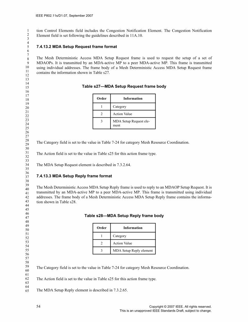
IEEE P802.11s/D1.07, September 2007
123456789
1011121314151617181920212223242526272829303132333435363738394041424344454647484950515253545556575859606162636465
tion Control Elements field includes the Congestion Notification Element. The Congestion NotificationElement field is set following the guidelines described in 11A.10.
7.4.13.2 MDA Setup Request frame format
The Mesh Deterministic Access MDA Setup Request frame is used to request the setup of a set ofMDAOPs. It is transmitted by an MDA-active MP to a peer MDA-active MP. This frame is transmittedusing individual addresses. The frame body of a Mesh Deterministic Access MDA Setup Request framecontains the information shown in Table s27.
The Category field is set to the value in Table 7-24 for category Mesh Resource Coordination.
The Action field is set to the value in Table s25 for this action frame type.
The MDA Setup Request element is described in 7.3.2.64.
7.4.13.3 MDA Setup Reply frame format
The Mesh Deterministic Access MDA Setup Reply frame is used to reply to an MDAOP Setup Request. It istransmitted by an MDA-active MP to a peer MDA-active MP. This frame is transmitted using individualaddresses. The frame body of a Mesh Deterministic Access MDA Setup Reply frame contains the informa-tion shown in Table s28.
The Category field is set to the value in Table 7-24 for category Mesh Resource Coordination.
The Action field is set to the value in Table s25 for this action frame type.
The MDA Setup Reply element is described in 7.3.2.65.
Table s27—MDA Setup Request frame body
Order Information
1 Category
2 Action Value
3 MDA Setup Request ele-ment
Table s28—MDA Setup Reply frame body
Order Information
1 Category
2 Action Value
3 MDA Setup Reply element
54 Copyright © 2007 IEEE. All rights reserved.This is an unapproved IEEE Standards Draft, subject to change.

IEEE P802.11s/D1.07, September 2007
123456789
1011121314151617181920212223242526272829303132333435363738394041424344454647484950515253545556575859606162636465
7.4.13.4 MDAOP Advertisement Request frame format
The MDAOP Advertisement Request frame is transmitted by an MDA-active MP to request MDA adver-tisements from neighbors. The frame body of an MDAOP Advertisement Request frame is shown inTable s29.
The Category field is set to the value in Table 7-24 for category Mesh Resource Coordination.
The Action field is set to the value in Table s25 for this action frame type.
7.4.13.5 MDAOP Advertisements frame format
The Mesh Deterministic Access MDAOP Advertisements frame is transmitted by an MDA-active MP toone or more peer MDA-active MPs. This frame may be transmitted using group addresses or individualaddresses. The frame body of a Mesh Deterministic Access MDAOP Advertisements frame contains theinformation shown in Table s30.
The Category field is set to the value in Table 7-24 for category Mesh Resource Coordination.
The Action field is set to the value in Table s25 for this action frame type.
The MDAOP Advertisements element is described in 7.3.2.66.
7.4.13.6 MDAOP Set Teardown frame format
The Mesh Deterministic Access MDAOP Set Teardown frame is transmitted by an MDA-active MP to oneor more peer MDA-active MPs. This frame may be transmitted using group addresses or individualaddresses. The frame body of a Mesh Deterministic Access MDAOP Set Teardown frame contains theinformation shown in Table s31.
The Category field is set to the value in Table 7-24 for category Mesh Resource Coordination.
Table s29—MDAOP Advertisement Request frame body
Order Information
1 Category
2 Action Value
Table s30—MDAOP Advertisements frame body
Order Information
1 Category
2 Action Value
3 MDA Advertisements ele-ment
Copyright © 2007 IEEE. All rights reserved. 55This is an unapproved IEEE Standards Draft, subject to change.

IEEE P802.11s/D1.07, September 2007
123456789
1011121314151617181920212223242526272829303132333435363738394041424344454647484950515253545556575859606162636465
The Action field is set to the value in Table s25 for this action frame type.
The MDAOP Set Teardown element is described in 7.3.2.67.
7.4.13.7 Beacon Timing Request frame format
The Beacon Timing Request frame is used to request beacon timing information from peer MPs. This frameis transmitted using group addresses or individual addresses. The frame body of a Beacon Timing Requestframe contains the information shown in Table s27.
The Category field is set to the value in Table 7-24 for category Mesh Resource Coordination.
The Action field is set to the value in Table s25 for this action frame type.
7.4.13.8 Beacon Timing Response frame format
The Beacon Timing Response frame is used to respond to a Beacon Timing Request frame with neighborMP beacon timing information. This frame is transmitted using individual addresses. The frame body of aBeacon Timing Response frame contains the information shown in Table s33.
Table s31—MDAOP Set Teardown frame body
Order Information
1 Category
2 Action Value
3 MDA Set Teardown ele-ment
Table s32—Beacon Timing Request frame body
Order Information
1 Category
2 Action Value
Table s33—Beacon Timing Response frame body
Order Information
1 Category
2 Action Value
3 Most Recent TBTT
4 Beacon Timing element
56 Copyright © 2007 IEEE. All rights reserved.This is an unapproved IEEE Standards Draft, subject to change.

IEEE P802.11s/D1.07, September 2007
123456789
1011121314151617181920212223242526272829303132333435363738394041424344454647484950515253545556575859606162636465
The Category field is set to the value in Table 7-24 for category Mesh Resource Coordination.
The Action field is set to the value in Table s25 for this action frame type.
The Most Recent TBTT information is an 8-octet field that reflects the most recent TBTT of the transmittingMP, measured in units of microseconds, so that the beacon timing information element reflects informationas if it was transmitted in a beacon at that TBTT.
The Beacon Timing element is set as described in 7.3.2.63.
7.4.13.9 Mesh Channel Switch Announcement frame format
The Mesh Channel Switch Announcement frame is transmitted by an MP to signal a channel switch asdescribed in 11A.3.3. This frame may be transmitted using group addresses or individual addresses. Theframe body of a Mesh Channel Switch Announcement frame contains the information shown in Table s34.
The Category field is set to the value in Table 7-24 for category Mesh Resource Coordination.
The Action field is set to the value in Table s25 for this action frame type.
The Mesh Channel Switch Announcement element is set as described in 7.3.2.59.
Insert the following after 7.4:
EDITORIAL NOTE—TGn defined 7.4a -- first unused is 7.4b.
7.4b Multihop Action (4-addr action frames)
This subclause describes the Multihop Action frame formats allowed for relevant action categories definedin Table 7-24 in 7.3.1.11.
7.4b.1 Mesh Security Architecture action details
Six Multihop Action frame formats are defined for MSA. An Action Value field, in the octet field immedi-ately after the Category field, differentiates the formats. The Action Value field values associated with eachframe format are defined in Table s35.
Table s34—Mesh Channel Switch Announcement frame body
Order Information
1 Category
2 Action Value
3 Mesh Channel Switch Announcement element
Copyright © 2007 IEEE. All rights reserved. 57This is an unapproved IEEE Standards Draft, subject to change.
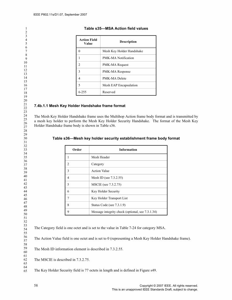
IEEE P802.11s/D1.07, September 2007
123456789
1011121314151617181920212223242526272829303132333435363738394041424344454647484950515253545556575859606162636465
7.4b.1.1 Mesh Key Holder Handshake frame format
The Mesh Key Holder Handshake frame uses the Multihop Action frame body format and is transmitted bya mesh key holder to perform the Mesh Key Holder Security Handshake. The format of the Mesh KeyHolder Handshake frame body is shown in Table s36.
The Category field is one octet and is set to the value in Table 7-24 for category MSA.
The Action Value field is one octet and is set to 0 (representing a Mesh Key Holder Handshake frame).
The Mesh ID information element is described in 7.3.2.55.
The MSCIE is described in 7.3.2.75.
The Key Holder Security field is 77 octets in length and is defined in Figure s49.
Table s35—MSA Action field values
Action Field Value Description
0 Mesh Key Holder Handshake
1 PMK-MA Notification
2 PMK-MA Request
3 PMK-MA Response
4 PMK-MA Delete
5 Mesh EAP Encapsulation
6-255 Reserved
Table s36—Mesh key holder security establishment frame body format
Order Information
1 Mesh Header
2 Category
3 Action Value
4 Mesh ID (see 7.3.2.55)
5 MSCIE (see 7.3.2.75)
6 Key Holder Security
7 Key Holder Transport List
8 Status Code (see 7.3.1.9)
9 Message integrity check (optional, see 7.3.1.34)
58 Copyright © 2007 IEEE. All rights reserved.This is an unapproved IEEE Standards Draft, subject to change.

IEEE P802.11s/D1.07, September 2007
123456789
1011121314151617181920212223242526272829303132333435363738394041424344454647484950515253545556575859606162636465
The Handshake Sequence subfield contains a sequence number, represented as an unsigned binary number,used to differentiate messages in a handshake.
The MA-Nonce field contains a pseudo-random value chosen by the MA. It is encoded following the con-ventions from 7.1.1.
The MKD-Nonce field contains a pseudo-random value chosen by the MKD. It is encoded following theconventions from 7.1.1.
The MA-ID field contains the MAC address of the MA. It is encoded following the conventions from 7.1.1.
The MKD-ID field contains the MAC address of the MKD. It is encoded following the conventions from7.1.1.
The Key Holder Transport field is defined in Figure s50.
The Key Holder Transport Count subfield indicates the number of transport type selectors that are containedin the Key Holder Transport List subfield.
The Key Holder Transport List subfield contains a series of transport type selectors that indicate Key HolderTransport protocols. The transport type selector format is given in Figure s48. The transport types definedby this standard are provided in Table s10. If the Key Holder Transport Count field is set to zero, then thissubfield is not present.
The Status Code field is described in 7.3.1.9.
The optional Message integrity check field is described in 7.3.1.34. The inclusion of the Message integritycheck field is dependent upon the value of the Handshake Sequence subfield of the Key Holder Securityfield. The Message integrity check field is omitted when Handshake Sequence is 1; otherwise, it is present.
7.4b.1.2 PMK-MA Notification frame format
The PMK-MA Notification frame uses the Multihop Action frame body format and is transmitted by anMKD in the Mesh Key Push protocol. The format of the PMK-MA Notification frame body is shown inTable s37.
Octets: 1 32 32 6 6
Handshake Sequence
MA-Nonce
MKD-Nonce
MA-ID MKD-ID
Figure s49—Key holder security field
Octets: 1 variable
Key Holder Transport Count Key Holder Transport List
Figure s50—Key Holder Transport field
Copyright © 2007 IEEE. All rights reserved. 59This is an unapproved IEEE Standards Draft, subject to change.
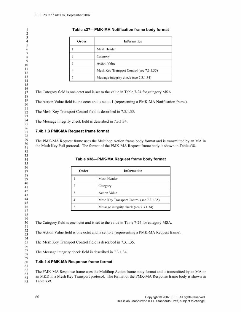
IEEE P802.11s/D1.07, September 2007
123456789
1011121314151617181920212223242526272829303132333435363738394041424344454647484950515253545556575859606162636465
The Category field is one octet and is set to the value in Table 7-24 for category MSA.
The Action Value field is one octet and is set to 1 (representing a PMK-MA Notification frame).
The Mesh Key Transport Control field is described in 7.3.1.35.
The Message integrity check field is described in 7.3.1.34.
7.4b.1.3 PMK-MA Request frame format
The PMK-MA Request frame uses the Multihop Action frame body format and is transmitted by an MA inthe Mesh Key Pull protocol. The format of the PMK-MA Request frame body is shown in Table s38.
The Category field is one octet and is set to the value in Table 7-24 for category MSA.
The Action Value field is one octet and is set to 2 (representing a PMK-MA Request frame).
The Mesh Key Transport Control field is described in 7.3.1.35.
The Message integrity check field is described in 7.3.1.34.
7.4b.1.4 PMK-MA Response frame format
The PMK-MA Response frame uses the Multihop Action frame body format and is transmitted by an MA oran MKD in a Mesh Key Transport protocol. The format of the PMK-MA Response frame body is shown inTable s39.
Table s37—PMK-MA Notification frame body format
Order Information
1 Mesh Header
2 Category
3 Action Value
4 Mesh Key Transport Control (see 7.3.1.35)
5 Message integrity check (see 7.3.1.34)
Table s38—PMK-MA Request frame body format
Order Information
1 Mesh Header
2 Category
3 Action Value
4 Mesh Key Transport Control (see 7.3.1.35)
5 Message integrity check (see 7.3.1.34)
60 Copyright © 2007 IEEE. All rights reserved.This is an unapproved IEEE Standards Draft, subject to change.

IEEE P802.11s/D1.07, September 2007
123456789
1011121314151617181920212223242526272829303132333435363738394041424344454647484950515253545556575859606162636465
The Category field is one octet and is set to the value in Table 7-24 for category MSA.
The Action Value field is one octet and is set to 3 (representing a PMK-MA Response frame).
The Key Transport Response field contains unsigned binary integer indicating a response type. The validKey Transport Response values are given in Table s39.
The Mesh Key Transport Control field is described in 7.3.1.35.
The optional Mesh Wrapped Key field is described in 7.3.1.36. The inclusion of the Mesh Wrapped Keyfield is dependent upon the value of the Key Transport Response field. The Mesh Wrapped Key field isincluded when Key Transport Response is zero; otherwise, it is omitted.
The Message integrity check field is described in 7.3.1.34.
7.4b.1.5 PMK-MA Delete frame format
The PMK-MA Delete frame uses the Multihop Action frame body format and is transmitted by an MKD inthe Mesh Key Delete protocol. The format of the PMK-MA Delete frame body is shown in Table s41.
The Category field is one octet and is set to the value in Table 7-24 for category MSA.
The Action Value field is one octet and is set to 4 (representing a PMK-MA Delete frame).
Table s39—PMK-MA Response frame body format
Order Information
1 Mesh Header
2 Category
3 Action Value
4 Key Transport Response
5 Mesh Key Transport Control (see 7.3.1.35)
6 Mesh Wrapped Key (optional: see 7.3.1.36)
7 Message integrity check (see 7.3.1.34)
Table s40—Key Transport Response values
Key Transport Response
Meaning
0 PMK-MA Delivery
1 Unable to deliver requested PMK-MA
2 Key Delete Acknowledged
3-255 Reserved
Copyright © 2007 IEEE. All rights reserved. 61This is an unapproved IEEE Standards Draft, subject to change.
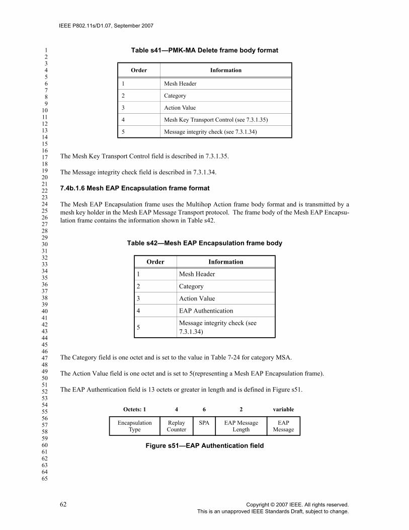
IEEE P802.11s/D1.07, September 2007
123456789
1011121314151617181920212223242526272829303132333435363738394041424344454647484950515253545556575859606162636465
The Mesh Key Transport Control field is described in 7.3.1.35.
The Message integrity check field is described in 7.3.1.34.
7.4b.1.6 Mesh EAP Encapsulation frame format
The Mesh EAP Encapsulation frame uses the Multihop Action frame body format and is transmitted by amesh key holder in the Mesh EAP Message Transport protocol. The frame body of the Mesh EAP Encapsu-lation frame contains the information shown in Table s42.
The Category field is one octet and is set to the value in Table 7-24 for category MSA.
The Action Value field is one octet and is set to 5(representing a Mesh EAP Encapsulation frame).
The EAP Authentication field is 13 octets or greater in length and is defined in Figure s51.
Table s41—PMK-MA Delete frame body format
Order Information
1 Mesh Header
2 Category
3 Action Value
4 Mesh Key Transport Control (see 7.3.1.35)
5 Message integrity check (see 7.3.1.34)
Table s42—Mesh EAP Encapsulation frame body
Order Information
1 Mesh Header
2 Category
3 Action Value
4 EAP Authentication
5Message integrity check (see 7.3.1.34)
Octets: 1 4 6 2 variable
Encapsulation Type
Replay Counter
SPA EAP Message Length
EAP Message
Figure s51—EAP Authentication field
62 Copyright © 2007 IEEE. All rights reserved.This is an unapproved IEEE Standards Draft, subject to change.

IEEE P802.11s/D1.07, September 2007
123456789
1011121314151617181920212223242526272829303132333435363738394041424344454647484950515253545556575859606162636465
The Encapsulation Type subfield identifies whether the message is an EAP Encapsulation Request or EAPEncapsulation Response message, and is set to a value described in Table s43.
The Replay Counter field contains a sequence number, represented as an unsigned binary number, used todetect replayed frames.
The SPA subfield contains the MAC address of the supplicant MP that is performing EAP authentication.
The EAP Message Length subfield is two octets and contains an unsigned binary integer indicating thelength in octets of the EAP message subfield. The EAP Message Length subfield contains the value zero ifthe EAP Message field is omitted.
The EAP Message subfield, when present, contains an EAP packet, with format as defined in IETF RFC3748.
The Message integrity check field is described in 7.3.1.34.
Table s43—Encapsulation Type values
Value Message Type
0 Reserved
1 Request
2 Response – Accept
3 Response – Reject
4-10 Reserved
11 Response
12-255 Reserved
Copyright © 2007 IEEE. All rights reserved. 63This is an unapproved IEEE Standards Draft, subject to change.

IEEE P802.11s/D1.07, September 2007
123456789
1011121314151617181920212223242526272829303132333435363738394041424344454647484950515253545556575859606162636465
8. Security
8.2 Pre-RSNA security methods
Insert the following text at the end of the first paragraph of 8.2:
Open System Authentication and De-authentication shall not be used between MPs.
8.4.1.1 Security association definitions
Insert the following items in the bulleted list in 8.4.1.1 after the first item (after PMKSA):
— PMK-MKD SA: A result of a successful Initial MSA authentication.— PMK-MA SA: A result of a successful Initial MSA authentication or Subsequent MSA authentica-
tion.
Insert the following two new subclauses after 8.4.1.1:
8.4.1.1.1A PMK-MKD SA
The PMK-MKD SA is the result of successful authentication during the Initial MSA authentication mecha-nism. The security association consists of the following elements:
— MKDD-ID— PMK-MKD— PMK-MKDName— SPA, and— authorization information including PMK-MKD lifetime.
8.4.1.1.1B PMK-MA SA
The PMK-MKD SA is the result of a successful Initial MSA authentication, or the successful completion ofthe Subsequent MSA authentication mechanism. The security association consists of the following ele-ments:
— PMK-MA,— PMK-MA lifetime,— PMK-MAName,— MA-ID,— PMK-MKDName,— SPA, and — authorization information.
8.5 Keys and key distribution
8.5.2 EAPOL-Key frames
Change List Item 1 of “Key Information” (list entry b) in 8.5.2 as shown:
1) Key Descriptor Version (bits 0-2) specifies the key descriptor version type.
64 Copyright © 2007 IEEE. All rights reserved.This is an unapproved IEEE Standards Draft, subject to change.

IEEE P802.11s/D1.07, September 2007
123456789
1011121314151617181920212223242526272829303132333435363738394041424344454647484950515253545556575859606162636465
i) The value 1 shall be used for all EAPOL-Key frames to and from a STA when neither thegroup nor pairwise ciphers are CCMP for Key Descriptor 1. This value indicates the fol-lowing:
—HMAC-MD5 is the EAPOL-Key MIC.
—ARC4 is the EAPOL-Key encryption algorithm used to protect the Key Data field.
ii) The value 2 shall be used for all EAPOL-Key frames to and from a STA when either thepairwise or the group cipher is AES-CCMP for Key Descriptor 2. This value indicates thefollowing:
—HMAC-SHA1-128 is the EAPOL-Key MIC. HMAC is defined in IETF RFC 2104; andSHA1, by FIPS PUB 180-1-1995. The output of the HMAC-SHA1 shall be truncated toits 128 MSBs (octets 0-15 of the digest output by HMAC-SHA1), i.e., the last four octetsgenerated shall be discarded.
—The NIST AES key wrap is the EAPOL-Key encryption algorithm used to protect theKey Data field. IETF RFC 3394 defines the NIST AES key wrap algorithm.
iii) The value 3 shall be used for all EAPOL-Key frames between MPs whendot11RSNAAuthenticationSuiteSelected is 5 or 6. This value indicates the following:
—AES-128-CMAC is the EAPOL-Key MIC. AES-128-CMAC is defined by FIPSSP800-38B. The output of the AES-128-CMAC shall be 128 bits.
—The NIST AES key wrap is the EAPOL-Key encryption algorithm used to protect theKey Data field. IETF RFC 3394 defines the NIST AES key wrap algorithm.
Change list entry h, “Key MIC” in 8.5.2 as shown:
h) Key MIC. This field is 16 octets in length when the Key Descriptor Version subfield is 1, 2 or 23.The EAPOL-Key MIC is a MIC of the EAPOL-Key frames, from and including the EAPOL proto-col version field to and including the Key Data field, calculated with the Key MIC field set to 0. Ifthe Encrypted Key Data subfield (of the Key Information field) is set, the Key Data field isencrypted prior to computing the MIC.
1) Key Descriptor Version 1: HMAC-MD5; IETF RFC 2104 and IETF RFC 1321 together definethis function.
2) Key Descriptor Version 2: HMAC-SHA1-128.
3) Key Descriptor Version 3: AES-128-CMAC.
Copyright © 2007 IEEE. All rights reserved. 65This is an unapproved IEEE Standards Draft, subject to change.

IEEE P802.11s/D1.07, September 2007
123456789
1011121314151617181920212223242526272829303132333435363738394041424344454647484950515253545556575859606162636465
Insert the following entry in Table 8-4 (KDE) and changed the Reserved row as shown:
Insert the following text and Figure after Figure 8-32 in 8.5.2:
The format of the Mesh GTK Delivery KDE is shown in Figure s52.
8.5.2.1 EAPOL-Key frame notation
Change the text as follows:
Lifetime is the key lifetime KDE used for sending the expiry timeout value for SMK used during PeerKey Handshake for STA-to-STA SMK key identification. The lifetime KDE is also used during MSA Authentication in a mesh to express the timeout value of the PMK-MA.
8.5.3 4-Way Handshake
8.5.3.1 4-Way Handshake Message 1
Change 8.5.3.1 as follows:
Key Information:
Key Descriptor Version = 1 (ARC4 encryption with HMAC-MD5) or 2 (NIST AES key wrap withHMAC-SHA1-128) or 3 (NIST AES key wrap with AES-128-CMAC)
Table 8-4—KDE
OUI Data Type Meaning
00-0F-AC 9 Mesh GTK Delivery KDE
00-0F-AC 910-255
Sender MP Address
Destination MP Address
6 octets 6 octets
Figure s52—Mesh GTK Delivery KDE format
66 Copyright © 2007 IEEE. All rights reserved.This is an unapproved IEEE Standards Draft, subject to change.

IEEE P802.11s/D1.07, September 2007
123456789
1011121314151617181920212223242526272829303132333435363738394041424344454647484950515253545556575859606162636465
8.5.3.2 4-Way Handshake Message 2
Change 8.5.3.2 as follows:
Key Information:
Key Descriptor Version = 1 (ARC4 encryption with HMAC-MD5) or 2 (NIST AES key wrap withHMAC-SHA1-128) or 3 (NIST AES key wrap with AES-128-CMAC) - same as Message 1.
8.5.3.3 4-Way Handshake Message 3
Change 8.5.3.3 as follows:
Key Information:
Key Descriptor Version = 1 (ARC4 encryption with HMAC-MD5) or 2 (NIST AES key wrap withHMAC-SHA1-128) or 3 (NIST AES key wrap with AES-128-CMAC) - same as Message 1.
8.5.3.4 4-Way Handshake Message 4
Change 8.5.3.4 as follows:
Key Information:
Key Descriptor Version = 1 (ARC4 encryption with HMAC-MD5) or 2 (NIST AES key wrap withHMAC-SHA1-128) or 3 (NIST AES key wrap with AES-128-CMAC) - same as Message 1.
8.5.4 Group Key Handshake
8.5.4.1 Group Key Handshake Message 1
Change 8.5.4.1 as follows:
Key Information:
Key Descriptor Version = 1 (ARC4 encryption with HMAC-MD5) or 2 (NIST AES key wrap withHMAC-SHA1-128) or 3 (NIST AES key wrap with AES-128-CMAC)
8.5.4.2 Group Key Handshake Message 2
Change 8.5.4.2 as follows:
Key Information:
Key Descriptor Version = 1 (ARC4 encryption with HMAC-MD5) or 2 (NIST AES key wrap withHMAC-SHA1-128) or 3 (NIST AES key wrap with AES-128-CMAC) - same as Message 1.
Insert the following new clause after 8.7:
8.8 Key distribution for MSA
8.8.1 Overview
This subclause describes the mesh key hierarchy and its supporting architecture. The mesh key hierarchy per-
Copyright © 2007 IEEE. All rights reserved. 67This is an unapproved IEEE Standards Draft, subject to change.

IEEE P802.11s/D1.07, September 2007
123456789
1011121314151617181920212223242526272829303132333435363738394041424344454647484950515253545556575859606162636465
mits an MP to create secure associations with peer MPs without the need to perform an IEEE 802.1X authen-tication each time. The mesh key hierarchy can be used with either IEEE 802.1X authentication or PSKauthentication. It is assumed by this standard that the PSK is specific to a single MP and a single MKD.
A key hierarchy consisting of two branches is introduced for use within a mesh, and is shown in Figure s53.A link security branch consists of three levels, supporting distribution of keys between mesh key holders topermit the use of the mesh key hierarchy between a supplicant MP and an MA. A key distribution branchprovides keys to secure the transport and management of keys between mesh key holders.
In the link security branch, the first level key (PMK-MKD) is derived by the MKD from either the PSK orfrom the MSK resulting (per IETF RFC 3748) from a successful IEEE 802.1X Authentication between theAS and the supplicant MP. One or more second level keys (PMK-MAs) are derived from the PMK-MKD.Each PMK-MA may be used to derive one or more PTKs.
In the key distribution branch, the first level key (MKDK) is derived from either the PSK or MSK. A secondlevel key (MPTK-KD) is derived from the MKDK during the mechanism described in 11A.2.3.2. TheMKDK permits derivation of more than one MPTK-KD, if required.
As shown in Figure s54, the mesh key distributor (MKD) generates the first level key for both branches fromeither the PSK or the MSK The second level keys in both branches are generated by the MKD as well. Aunique PMK-MA may be delivered from the MKD to each MA using a secure protocol, as described in11A.2.4. Figure s53 illustrates an example of two unique PMK-MAs being distributed to two MAs, labeled(a) and (b).
Upon a successful authentication between a supplicant MP and the MKD, the supplicant MP and the MKDshall delete the prior PMK-MKD, MKDK, and MPTK-KD keys and all PMK-MA keys that were created be-tween the supplicant MP and the same MKD domain. Upon receiving a new PMK-MA key for a supplicantMP, an MA shall delete the prior PMK-MA key and all PTKs derived from the prior PMK-MA key.
The lifetime of all keys derived from the PSK or MSK are bound to the lifetime of the PSK or MSK. Forexample, the IEEE 802.1X AS may communicate the MSK key lifetime with the MSK. If such an attributeis provided, the lifetimes of the PMK-MKD and MKDK shall be not more than the lifetime of the MSK. Ifthe MSK lifetime attribute is not provided, or for PSK, the key lifetime shall be the value of the MIB variabledot11MeshFirstLevelKeyLifetime.
The lifetime of the PTK and PMK-MA shall be the same as that of the PMK-MKD and the lifetime of theMPTK-KD shall be the same as that of the MKDK, as calculated above. When the key lifetime expires, eachkey holder shall delete their respective derived keys.
The mesh key hierarchy derives its keys using the Key Derivation Function (KDF) as defined in 8.8.3 withseparate labels to further distinguish derivations.
The operations performed by mesh key holders and the movement of keys within the mesh key hierarchy are
68 Copyright © 2007 IEEE. All rights reserved.This is an unapproved IEEE Standards Draft, subject to change.

IEEE P802.11s/D1.07, September 2007
123456789
1011121314151617181920212223242526272829303132333435363738394041424344454647484950515253545556575859606162636465
shown in Figure s54.
Figure s53—Mesh key hierarchy
Figure s54—Key distribution between mesh key holders
8.8.2 Key hierarchy
The mesh key hierarchy consists of two branches whose keys are derived using the KDF described in 8.8.3.
The first branch, the link security branch, consists of three levels and results in a PTK for use in securing alink.
— PMK-MKD – The first level of the link security branch, this key is derived as a function of the MSKor PSK and the Mesh ID. It is cached by the supplicant MP and the PMK-MKD key holder, namelythe MKD. This key is mutually derived by the supplicant MP and the MKD. There is only a singlePMK-MKD derived between the supplicant MP and the MKD domain.
MSK or PSK
PMK-MKD
PMK-MA*
MKDK
MPTK-KD*
PTK*
*Multiple keys may be derived.
MSK or PSK
PMK-MKD
PMK-MA*
MKDK
MPTK-KD*
PTK*
*Multiple keys may be derived.
Authentication Server(802.1X Authentication only)
Mesh Key DistributorMKD-ID
Derives PMK-MKD, PMK-MAsDerives MKDK and MPTK-KD
Mesh Authenticator(a)MA-ID(a)
Derives PTK(a)
Mesh Authenticator(b)MA-ID(b)
Derives PTK(b)
MSK PSK
PMK-MA(b)PMK-MA(a)
Authentication Server(802.1X Authentication only)
Mesh Key DistributorMKD-ID
Derives PMK-MKD, PMK-MAsDerives MKDK and MPTK-KD
Mesh Authenticator(a)MA-ID(a)
Derives PTK(a)
Mesh Authenticator(b)MA-ID(b)
Derives PTK(b)
Mesh Authenticator(a)MA-ID(a)
Derives PTK(a)
Mesh Authenticator(b)MA-ID(b)
Derives PTK(b)
MSK PSK
PMK-MA(b)PMK-MA(a)
Copyright © 2007 IEEE. All rights reserved. 69This is an unapproved IEEE Standards Draft, subject to change.

IEEE P802.11s/D1.07, September 2007
123456789
1011121314151617181920212223242526272829303132333435363738394041424344454647484950515253545556575859606162636465
— PMK-MA – The second level of the link security branch, this key is mutually derived by the suppli-cant MP and the MKD. It is delivered by the MKD to an MA to permit completion of an MSAhandshake between the supplicant MP and the MA.
— PTK – The third level of the link security branch that defines the IEEE 802.11 and IEEE 802.1X pro-tection keys. The PTK is mutually derived by the supplicant and the PMK-MA key holder, namelythe MA.
The PTK is used as defined by 8.5 for secure link operation.
The second branch, the key distribution branch, consists of two levels and results in a MPTK-KD for use inallowing an MP to become an MA, and in securing communications between an MA and the MKD.
— MKDK – The first level of the key distribution branch, this key is derived as a function of the MSKor PSK and the Mesh ID and cached by the supplicant MP and the MKD. This key is mutuallyderived by the supplicant MP and the MKD. There is only a single MKDK derived between the sup-plicant MP and the MKD.
— MPTK-KD – The second level of the key distribution branch that defines protection keys for com-munication between MA and MKD. The MPTK-KD is mutually derived by the supplicant MP(when it becomes an MA) and the MKD.
8.8.3 Key derivation function
The key derivation function for the mesh key hierarchy, KDF, is a variant of the PRF function defined in8.5.1.1, and defined as follows:
Output = KDF-Length (K, label, Context) where Input: K, a 256 bit key derivation key
label, a string identifying the purpose of the keys derived using this KDF Context, a bit string that provides context to identify the derived key Length, the length of the derived key in bits
Output: a Length-bit derived key
result = "" iterations = (Length+255)/256 do i = 1 to iterations result = result || HMAC-SHA256(K, i || label || 0x00 || Context || Length) od return first Length bits of result, and securely delete all unused bits
In this algorithm, i and Length are encoded as 16-bit unsigned integers, represented using the bit ordering con-ventions of 7.1.1.
8.8.4 PMK-MKD
The first level key of the mesh key hierarchy link security branch, PMK-MKD binds the SPA, MKD domainidentifier, MKD-NAS-ID, and Mesh ID with the keying material resulting from the negotiated AKM. ThePMK-MKD is the top level 256-bit keying material used to derive the next level keys (PMK-MAs):
PMK-MKD = KDF-256(XXKey, “MKD Key Derivation”, MeshIDlength || MeshID ||NASIDlength || MKD-NAS-ID || MKDD-ID || SPA || MPTKANonce)
where
70 Copyright © 2007 IEEE. All rights reserved.This is an unapproved IEEE Standards Draft, subject to change.

IEEE P802.11s/D1.07, September 2007
123456789
1011121314151617181920212223242526272829303132333435363738394041424344454647484950515253545556575859606162636465
— KDF-256 is the KDF function as defined in 8.8.3 used to generate a key of length 256 bits.— If the AKM negotiated is 00-0F-AC:5, then XXKey shall be the second 256 bits of the MSK (MSK
being derived from the IEEE 802.1X authentication), i.e., XXKey = L(MSK, 256, 256). If the AKMnegotiated is 00-0F-AC:6, then XXKey shall be the PSK.
— “MKD Key Derivation” is 0x4D4B44204B65792044657269766174696F6E.— MeshIDLength is a single octet whose value is the number of octets in the Mesh ID.— Mesh ID is the mesh identifier, a variable length sequence of octets, as it appears in the Beacon
frames and Probe Response frames.— NASIDlength is a single octet whose value is the number of octets in the MKD-NAS-ID.— MKD-NAS-ID is the identifier of the MKD sent from the 802.1X Authenticator MP to the 802.1X
Supplicant MP during Initial MSA Authentication.— MKDD-ID is the 6-octet MKD domain identifier field from the Mesh security capability information
element that was used during Initial MSA Authentication.— SPA is the supplicant MP’s MAC address.— MPTKANonce is an unpredictable 256-bit pseudo-random value generated by the PMK-MKD
holder (MKD), delivered along with PMK-MA to the MA, and provided by the MA to the suppli-cant MP during Initial MSA Authentication.
The PMK-MKD is referenced and named as follows:
PMK-MKDName = Truncate-128(SHA-256(“MKD Key Name” || MeshIDlength || MeshID ||NASIDlength || MKD-NAS-ID || MKDD-ID || SPA || MPTKANonce))
where— “MKD Key Name” is 0x4D4B44204B6579204E616D65.— Truncate-128(-) returns the first 128 bits of its argument, and securely destroys the remainder.
8.8.5 PMK-MA
The second level key of the mesh key hierarchy link security branch, PMK-MA, is a 256-bit key used to de-rive the PTK. The PMK-MA binds the SPA, MKD, and MA:
PMK-MA = KDF-256(PMK-MKD, “MA Key Derivation”, PMK-MKDName || MA-ID || SPA)
where— KDF-256 is the KDF function as defined in 8.8.3 used to generate a key of length 256 bits.— PMK-MKD is the key defined in 8.8.4.— “MA Key Derivation” is 0x4D41204B65792044657269766174696F6E.— PMK-MKDName is defined in 8.8.4.— MA-ID is the identifier of the holder of PMK-MA (MA).— SPA is the supplicant MP’s MAC address.
The PMK-MA is referenced and named as follows:
PMK-MAName = Truncate-128(SHA-256(“MA Key Name” || PMK-MKDName || MA-ID ||SPA))
where— “MA Key Name” is 0x4D41204B6579204E616D65.
Copyright © 2007 IEEE. All rights reserved. 71This is an unapproved IEEE Standards Draft, subject to change.

IEEE P802.11s/D1.07, September 2007
123456789
1011121314151617181920212223242526272829303132333435363738394041424344454647484950515253545556575859606162636465
8.8.6 PTK
The third level key of the mesh key hierarchy link security branch is the PTK. This key is mutually derivedby the Supplicant MP and the MA with the key length being a function of the negotiated cipher suites as de-fined by Table 8-2 in 8.5.2.
The PTK derivation is as follows:
PTK = KDF-PTKLen(PMK-MA, “Mesh PTK Key derivation”, MPTKSNonce || MPTKANonce ||MA-ID || SPA || PMK-MAName)
where— KDF-PTKLen is the KDF function as defined in 8.8.3 used to generate a PTK of length PTKLen.— PMK-MA is the key that is shared between the Supplicant MP and the MA— “Mesh PTK Key derivation” is 0x4D6573682050544B204B65792064657269766174696F6E.— MPTKSNonce is a 256 bit pseudo-random bit string contributed by the Supplicant MP— MPTKANonce is a 256 bit pseudo-random string contributed by the MKD or MA— SPA is the Supplicant MP’s MAC address— MA-ID is the MAC address of the MA.— PMK-MAName is defined in 8.8.5— PTKlen is the total number of bits to derive, e.g., number of bits of the PTK. The length is dependent
on the negotiated cipher suites as defined by Table 8-2 in 8.5.2.
Each PTK has three component keys, KCK, KEK, and TK, derived as follows:
The KCK shall be computed as the first 128 bits (bits 0-127) of the PTK:
KCK = L(PTK, 0, 128)
where L(-) is defined in 8.5.1.
The KCK is used to provide data origin authenticity between a supplicant MP and the MA when used inEAPOL-Key frames defined in 8.5.2.
The KEK shall be computed as bits 128-255 of the PTK:
KEK = L(PTK, 128, 128)
The KEK is used to provide data confidentiality between a supplicant MP and the MA when used in EAPOL-Key frames defined in 8.5.2.
Temporal keys (TK) shall be computed as bits 256-383 (for CCMP) or bits 256-511 (for TKIP) of the PTK:
TK = L(PTK, 256, 128), or TK = L(PTK, 256, 256)
The temporal key is configured into the Supplicant MP through the use of the MLME-SETKEYS.requestprimitive. The MP uses the temporal key with the pairwise cipher suite; interpretation of this value is cipher-suite specific.
The PTK is referenced and named as follows:
72 Copyright © 2007 IEEE. All rights reserved.This is an unapproved IEEE Standards Draft, subject to change.

IEEE P802.11s/D1.07, September 2007
123456789
1011121314151617181920212223242526272829303132333435363738394041424344454647484950515253545556575859606162636465
PTKName = Truncate-128(SHA-256(“Mesh PTK Name” || PMK-MAName || MPTKSNonce ||MPTKANonce || MA-ID || SPA))
where— “Mesh PTK Name” is 0x4D6573682050544B204E616D65.
8.8.7 MKDK
The first level key of the key distribution branch, MKDK binds the MA-ID (the MAC address of the MP es-tablishing the MKDK to become an MA), MKD domain identifier, and Mesh ID with the keying material re-sulting from the negotiated AKM. The MKDK is used to derive the MPTK-KD.
MKDK = KDF-256(XXKey, “Mesh Key Distribution Key”, MeshIDLength || MeshID ||NASIDlength || MKD-NAS-ID || MKDD-ID || MA-ID || MPTKANonce)
where— KDF-256 is the KDF function as defined in 8.8.3 used to generate a key of length 256 bits.— If the AKM negotiated is 00-0F-AC:5, then XXKey shall be the second 256 bits of the MSK (MSK
being derived from the IEEE 802.1X authentication), i.e., XXKey = L(MSK, 256, 256). If the AKMnegotiated is 00-0F-AC:6, then XXKey shall be the PSK.
— “Mesh Key Distribution Key” is 0x4D657368204B657920446973747269627574696F6E204B6579.— MeshIDLength is a single octet whose value is the number of octets in the Mesh ID.— Mesh ID is the mesh identifier, a variable length sequence of octets, as it appears in the Beacon
frames and Probe Response frames.— NASIDlength is a single octet whose value is the number of octets in the MKD-NAS-ID.— MKD-NAS-ID is the identifier of the MKD sent from the 802.1X Authenticator MP to the 802.1X
Supplicant MP during Initial MSA Authentication.— MKDD-ID is the 6-octet MKD domain identifier field from the Mesh security capability information
element that was used during Initial MSA Authentication.— MA-ID is the MAC address of the MP establishing a security association with the MKD in order to
become configured as an MA.— MPTKANonce is identical to the value used to calculate PMK-MKDName, as described in 8.8.4.
The KDK is referenced and named as follows:
MKDKName = Truncate-128(SHA-256(“MKDK Name” || MeshIDLength || MeshID ||NASIDlength || MKD-NAS-ID || MKDD-ID || MA-ID || MPTKANonce))
where— “MKDK Name” is 0x4D4B444B204E616D65.— Truncate-128(-) returns the first 128 bits of its argument, and securely destroys the remainder.
8.8.8 MPTK-KD
The second level key of the key distribution branch, MPTK-KD, is a 256-bit key that is mutually derived byan MA and an MKD. The MPTK-KD is derived:
MPTK-KD = KDF-256(MKDK, “Mesh PTK-KD Key”, MA-Nonce || MKD-Nonce || MA-ID ||MKD-ID)
Copyright © 2007 IEEE. All rights reserved. 73This is an unapproved IEEE Standards Draft, subject to change.
IEEE P802.11s/D1.07, September 2007
123456789
1011121314151617181920212223242526272829303132333435363738394041424344454647484950515253545556575859606162636465
where— MKDK is the key defined in 8.8.7.— “Mesh PTK-KD Key” is 0x4D6573682050544B2D4B44204B6579.— MA-Nonce is a 256-bit pseudo-random string contributed by the MA.— MKD-Nonce is a 256-bit pseudo-random string contributed by the MKD.— MA-ID is the MAC address of the MA.— MKD-ID is the MAC address of the MKD.
The MPTK-KD has two component keys, the Mesh Key confirmation key for key distribution (MKCK-KD)and the Mesh Key encryption key for key distribution (MKEK-KD), derived as follows:
The MKCK-KD shall be computed as the first 128 bits (bits 0-127) of the MPTK-KD:
MKCK-KD = L(MPTK-KD, 0, 128)
where L(-) is defined in 8.5.1.
The MKCK-KD is used to provide data origin authenticity in messages exchanged between MA and MKD,as defined in 11A.4.2.2.
The MKEK-KD shall be computed as bits 128-255 of the MPTK-KD:
MKEK-KD = L(MPTK-KD, 128, 128)
The MKEK-KD is used to provide data confidentiality in messages exchanged between MA and MKD, asdefined in 11A.4.2.2.
The MPTK-KD is referenced and named as follows:
MPTK-KDName = Truncate-128(SHA-256(MKDKName || “MPTK-KD Name” || MA-Nonce ||MKD-Nonce || MA-ID || MKD-ID))
where— “MPTK-KD Name” is 0x4D50544B2D4B44204E616D65.
Alternatively, the first 32 bits of the MPTK-KDName may be used to reference the MPTK-KD, such aswithin the context of a security association between MA and MKD, as follows:
MPTK-KDShortName = L(MPTK-KDName, 0, 32)
8.8.9 Mesh key holders
8.8.9.1 Key holder requirements
The MKD and MA are responsible for the derivation of keys in the mesh key hierarchy.
The MKD shall meet the following requirements.— The MKD shall provide NAS client (the client component of a Network Access Server that commu-
nicates with an Authentication Server) functionality.— The MKD domain identifier (MKDD-ID) uniquely identifies an MKD (i.e., there is a one-to-one
mapping between an MKD domain identifier and an MKD). The MKDD-ID is bound into the deri-vation of the first level keys (PMK-MKD and MKDK).
74 Copyright © 2007 IEEE. All rights reserved.This is an unapproved IEEE Standards Draft, subject to change.

IEEE P802.11s/D1.07, September 2007
123456789
1011121314151617181920212223242526272829303132333435363738394041424344454647484950515253545556575859606162636465
— The MKD NAS Identifier (MKD-NAS-ID) shall be set to the identity of the NAS Client provided bythe MKD (e.g., NAS-Identifier as defined in RFC 2865 if RADIUS is used as the backend protocol).MKD-NAS-ID shall not be longer than 48 octets. MKD-NAS-ID is bound into the derivation of thefirst level keys (PMK-MKD and MKDK).
— The mesh key distributor identifier (MKD-ID) shall be set to a MAC address of the physical entitythat stores the MKD. The MKD-ID is used in the generation of the MPTK-KD.
— When the PMK-MKD lifetime expires, the MKD shall delete the PMK-MKD SA and shall delete allPMK-MAs cached within the MKD that were derived from the PMK-MKD.
— The MKD shall not expose the PMK-MKD to other parties.
— The MKD shall not expose the PMK-MA to parties other than the authorized MA.
The MA shall meet the following requirements.
— The mesh authenticator identity (MA-ID) shall be set to a MAC address of the physical entity thatstores the PMK-MA and uses it to generate the PTK. That same MAC address shall be used toadvertise the MA identity to MPs and to the MKD.
— The MA shall provide the IEEE 802.1X Authenticator function, and its Port Access Entity shallauthorize the controlled Port for communication with a peer MP only upon installation of a PTKderived with the peer MP. The PTK shall be derived from a PMK-MA received from the MKD.
— The MA shall provide the IEEE 802.11 Authenticator function to derive and distribute the GTK toconnected MPs.
— When the PMK-MA lifetime expires, the MA shall delete the PMK-MA SA and shall revoke allPTKs derived from the PMK-MA using the MLME-DELETEKEYS primitive.
— The MA shall not expose the PMK-MA to other parties.
8.8.9.2 Authorization of mesh key holders
The authorization of an MKD is achieved through Initial MSA Authentication. An MP implementing theMKD function is authorized to be an MKD by any MP that performs authentication through the MKD.Explicitly, successful completion of Initial MSA Authentication, including the confirmed creation of themesh key hierarchy, provides authorization of the MKD identified by MKD-NAS-ID (an identity bound intothe PMK-MKD) to be an MKD for the MP performing authentication.
An MA is authorized by the MKD with which the MA communicates. If an MA is co-located with an MKD(in the same physical device), the MA function is authorized by the MKD due to the co-location. Otherwise,the authorization of the MA occurs through the Mesh key holder security association (11A.4.5). The firstmessage of the Mesh key holder security handshake (11A.4.5.2) contains the identity of the aspirant MA inthe MA-ID field. Upon receiving this message, the MKD shall locate the PMK-MKD SA that contains anSPA entry that is identical to the MA-ID received in the first message of the Mesh key holder security hand-shake. The MKD shall authorize the MA to receive PMK-MA keys if and only if (a) the contents of thePMK-MKD SA allow the authorization, and (b) the aspirant MA successfully completes the Mesh keyholder security handshake.
The distribution of PMK-MAs within a mesh shall satisfy the following requirements:
— Delivery of PMK-MA keys shall be performed using the protocol defined in 11A.4.6.
— A PMK-MA key shall be delivered to an MA only if the MA is authorized to receive PMK-MA keys.
— A PMK-MA key shall be delivered to an authorized MA only if the authorized identity of the MA(i.e., the MA-ID exchanged during the MA’s Mesh key holder security handshake) is identical to theMA-ID value used to derive the PMK-MA being delivered.
Copyright © 2007 IEEE. All rights reserved. 75This is an unapproved IEEE Standards Draft, subject to change.

IEEE P802.11s/D1.07, September 2007
123456789
1011121314151617181920212223242526272829303132333435363738394041424344454647484950515253545556575859606162636465
8.8.9.3 PMK-MA distribution within an MKD domain
An MKD domain is identified by the MKD domain identifier (MKDD-ID). An MKD domain contains a sin-gle MKD and at least one MA which has established a security association with the MKD.
An MP creates its mesh key hierarchy during the Initial MSA Authentication, utilizing information for-warded from the MKD by the MA. During the Initial MSA Authentication, the MKD derives the PMK-MKD from the MSK acquired during IEEE 802.1X authentication, when the negotiated AKM is 00-0F-AC:5, or from the PSK, when the negotiated AKM is 00-0F-AC:6.
Additionally, the MKD is responsible for deriving a PMK-MA for each MA within the MKD domain. TheMKD is responsible for transmitting the derived PMK-MA keys securely to those key holders, along with thePMK-MAName, the key lifetime, the PMK-MKDName used to derive the PMK-MA, and the MPTKANonceused in the calculation of PMK-MKDName.
The secure transmission of keys and key information from MKD to MA shall be through the use of the meshkey transport protocol described in 11A.4.2.2.
Each MA shall derive the PTK mutually with the supplicant MP.
76 Copyright © 2007 IEEE. All rights reserved.This is an unapproved IEEE Standards Draft, subject to change.

IEEE P802.11s/D1.07, September 2007
123456789
1011121314151617181920212223242526272829303132333435363738394041424344454647484950515253545556575859606162636465
9. MAC sublayer functional description
Insert the following new clause after 9.13:
EDITORIAL NOTE—The following clause numbering based on 11n/D2.0 ending with 9.20
9.21 MDA (Optional)
Mesh Deterministic Access (MDA) is an optional access method that allows supporting MPs that supportMDA to access the channel at selected times with lower contention than would otherwise be possible. Thisstandard does not require all MPs to use MDA. MDA can be used by a subset of MPs in a Mesh. However,MDA connections can only be setup among MDA-supporting MPs. The performance of MDA may beimpacted by devices that do not respect MDA reservations. MDA sets up time periods in mesh neighbor-hoods when a number of MDA-supporting MPs that may potentially interfere with each others’ transmis-sions or receptions are set to not initiate transmission sequences. In order to use the MDA method for access,an MP shall be a synchronizing MP. The MDA method is described in detail below.
9.21.1 MDA opportunity (MDAOP)
An MDAOP is a period of time within every Mesh DTIM interval that is set up between the MDAOP ownerand the addressed MP. Once an MDAOP is setup,
— Access to the channel by MDA-supporting MPs is goverened by the procedures in 9.21.9.1— The MDAOP is advertised according to the procedures in 9.21.7.
9.21.2 MDAOP sets
A set of MDAOPs may be setup for individually addressed transmissions from a transmitter to a receiver bythe transmitter. Such a set is identified by a unique ID called the MDAOP Set ID. The MDAOP Set ID has tobe unique for a transmitter, so that the MDAOP set ID and the transmitter (or set owner) MAC addressuniquely identifies an MDAOP set in the mesh. The MDAOP set ID is a handle that allows operation such assetup and teardown to be conducted together for the entire set of MDAOPs in an MDAOP set.
MDAOP set ID is an 8-bit unsigned number. The special value of MDAOP set ID, when all bits are set to 1,is reserved to mean all MDAOPs.
9.21.3 Neighborhood MDAOP times at an MP
In an MP’s mesh neighborhood, all the TX-RX times reported by its neighbors (in their MDAOP advertise-ments) form a set of MDAOPs that are already being used in the neighborhood. No new MDAOPs may beset up by the MP during these times. These times are referred to as Neighborhood MDAOP times for theMP. In effect, Neighborhood MDAOP Times at an MP include all MDAOPs for which the MP and itsneighbors are either the transmitters or receivers.
9.21.4 Neighbor MDAOP interfering times for an MP
Through the Interfering Times in its MDAOP Advertisements, the MP reports the MDAOP times which itsneighbors have advertised in their TX-RX reports and in which it is not involved itself. These times shallnot be used for a new MDAOP with the reporting MP as they may experience interference.
9.21.5 MDA access fraction (MAF)
The MDA access fraction at an MP is the ratio of the total duration of its ‘Neighborhood MDAOP Times’(see definition above) in a Mesh DTIM interval to the duration of the Mesh DTIM interval. This parameter
Copyright © 2007 IEEE. All rights reserved. 77This is an unapproved IEEE Standards Draft, subject to change.
IEEE P802.11s/D1.07, September 2007
123456789
1011121314151617181920212223242526272829303132333435363738394041424344454647484950515253545556575859606162636465
may be used to limit the use of MDA in an MP’s mesh neighborhood to a certain fraction of the total channeltime. The maximum value for MAF that is allowed at an MP is specified by the dot11MAFlimit parameter.
The dot11MAFlimit is copied into the MDA Access Fraction Limit field of the MDAOP Advertisementsinformation element. Before attempting to set up an MDAOP Set with a neighbor, an MP is required toensure that the new MDAOP set does not cause the MAF of its neighbors to exceed their MAF Limit. AnMDAOP setup request shall be refused by the intended receiver if the MAF limit of its own neighbors isexceeded due to the new setup.
9.21.6 MDAOP setup procedure
The setup of an MDAOP set is initiated by the intended transmitter, and is accepted/rejected by the intendedreceiver. Once accepted, the transmitter is referred to as the owner of the MDAOP. The setup procedure foran MDAOP set is as follows:
a) The MP that intends to be the transmitter in a new MDAOP set builds a map of NeighborhoodMDAOP times in the Mesh DTIM interval after hearing Advertisements from all of its neighborsthat have MDA active. If no advertisement was heard from a neighbor in the lastdot11MDAdvertPeriodMax, the MP may request the neighbor for MDAOP Advertisement.
b) Based on traffic characteristics, it then chooses MDAOP starting times and durations in the MeshDTIM interval that do not overlap with either its Neighborhood MDAOP Times or the NeighborMDAOP Interfering Times of the intended receiver. It also avoids using times that are known to it asbeing used by itself or one of its neighbors for other activities such as beacon transmissions.
c) It then verifies that the new MDAOP Set will not cause the MAF limit to be crossed for its neigh-bors. If MAF limit would be crossed for its neighbors, due to the new MDAOP Set, it suspends thesetup process.
d) If the MAF limits at all neighbors are respected despite the new MDAOP set, it transmits anMDAOP Setup request information element to the intended receiver with chosen MDAOP locationsand durations.
e) The receiver of the MDAOP Setup Request information element checks to see if the MDAOP timeshave overlap with its Neighborhood MDAOP Times. The receiver also checks if the new MDAOPSet will cause the MAF limit to be crossed for its neighbors. The MDAOP Setup Reply informationelement is used to reply to a setup request.
f) The receiver rejects the setup request if there are overlaps of the requested MDAOP set with itsNeighborhood MDAOP Times, or other times that it knows are set to be used by itself or its neigh-bors for activities such as beacon transmissions. It may suggest alternate times by including theoptional field Alternate suggested MDAOP in the MDAOP Setup Reply element.
g) The receiver also rejects the setup request if the MAF limit of itself or its neighbors will be exceededdue to the new setup.
h) If suitable, the receiver accepts the setup.
9.21.7 MDAOP advertisements
Every MP that has MDA active is required to advertise TX-RX and Interfering times using the MDAOPAdvertisements information element, at least once in dot11MDAdvertPeriodMax. These advertisements arealways transmitted in group addressed frames; either in Beacon frames or MDA action frames. The adver-tised times include:
a) TX-RX times report:1) All MDAOP times for which the MP is the transmitter or the receiver.2) All other times that it knows are busy/reserved such that it is either the transmitter or the
receiver. A non exhaustive list includes expected HCCA times for an MAP and self or neigh-bor’s expected beacon times.
78 Copyright © 2007 IEEE. All rights reserved.This is an unapproved IEEE Standards Draft, subject to change.

IEEE P802.11s/D1.07, September 2007
123456789
1011121314151617181920212223242526272829303132333435363738394041424344454647484950515253545556575859606162636465
b) Interfering times report:
1) All TX-RX times reported by the MP’s neighbors so that the MP is neither the transmitter northe receiver during those times.
9.21.8 MDAOP set teardown
An MDAOP set is successfully torn down once both the transmitter and the receiver stop advertising the setin their TX-RX times. Either the transmitter or the receiver may indicate a teardown by transmitting theMDAOP Set Teardown information element to the other communicating end (transmitter or the receiver).The teardown is assumed successful once the ACK is received, or maximum retry attempts are exceeded.
The transmitter assumes a successful teardown and stops using or advertising (in TX-RX times report) anMDAOP set if any of the following happens:
a) Its MDAOP Set Teardown information element is successfully Acked.
b) The maximum retries for the teardown information element it is transmitting are exceeded.
c) The receiver’s advertisement does not include the MDAOP set
d) The receiver is unreachable for greater than dot11MDAOPtimeout time
The receiver assumes a successful teardown and stops advertising an MDAOP set if any of the followinghappens:
a) Its MDAOP Set Teardown information element is successfully Acked.
b) The maximum retries for the teardown information element it is transmitting are exceeded.
c) The transmitter’s advertisement does not include the MDAOP set.
d) The transmitter is inactive for greater than dot11MDAOPtimeout time
The interfering times are directly derived from neighbors’ TX-RX times report. The interfering times reportreflects the latest TX-RX times reports from the neighbors.
9.21.9 Access during MDAOP
MDA-supporting MPs shall track Neighborhood MDAOP times when either they or their neighbors aretransmitters or receivers. The access behavior for MPs during the Neighborhood MDAOP times is describedbelow.
9.21.9.1 Access by MDAOP Owners
If an MP is the owner of an MDAOP and has an MSDU associated with an MDA session to transmit, it shallattempt to access the channel during the time set up for the MDAOP and obtain a TXOP using EDCA con-tention and backoff parameters for the Access Category of the MSDU as defined in 9.9.1.3.
An MP successfully obtains a TXOP when the MP completes a frame exchange with the receiver of theMSDU. If the MP successfully obtains a TXOP, it may transmit until the EDCA TXOP limit for the AccessCategory of the MSDU is reached. If the MP reaches the TXOP limit before the end of the MDAOP, the MPshould attempt to transmit additional MSDU(s) associated with the MDA session, if any are ready to betransmitted, by accessing the channel again during the MDAOP to obtain a subsequent TXOP.
If an MP accesses the channel during the MDAOP but fails to obtain either an initial or a subsequent TXOP,the MP shall perform the backoff procedure specified in 9.9.1.5.
Copyright © 2007 IEEE. All rights reserved. 79This is an unapproved IEEE Standards Draft, subject to change.
IEEE P802.11s/D1.07, September 2007
123456789
1011121314151617181920212223242526272829303132333435363738394041424344454647484950515253545556575859606162636465
After an MP successfully obtains the TXOP, if there are multiple MSDUs to be transmitted, the transmissionand retransmission rules for multiple MSDU transmission should use the rules specified in 9.9.1.4 and9.9.1.6.
When an MP prepares to access the channel for a retransmission outside an MDAOP, the MP shall avoidaccess the channel during its neighbor's MDAOP times by setting its NAV during these times.
9.21.9.2 Access by non-owners of MDAOP
All MDA supporting MPs other than the MDAOP owner shall defer initiating tranmissions during theTXOP initiated in the MDAOP. MDA MPs that are not the owner of the current MDAOP can start contend-ing for access to the channel after the conclusion of the TXOP initiated in the current MDAOP.
80 Copyright © 2007 IEEE. All rights reserved.This is an unapproved IEEE Standards Draft, subject to change.

IEEE P802.11s/D1.07, September 2007
123456789
1011121314151617181920212223242526272829303132333435363738394041424344454647484950515253545556575859606162636465
10. Layer management
10.3 MLME SAP interface
EDITORIAL NOTE—11ma ended with 10.3.29, 11k added 30-33, 11r added 34-35, 11y added 36, 11n added 38
Insert the following new clause after 10.3.38:
10.3.39 PassivePeerLinkOpen
The following primitives describe how a mesh entity passively starts a peer link establishment process.
10.3.39.1 MLME-PassivePeerLinkOpen.request
10.3.39.1.1 Function
This primitive requests that the mesh entity start the link establishment protocol passively.
10.3.39.1.2 Semantics of the service primitive
The primitive parameters are as follows:
MLME-PassivePeerLinkOpen.request(localLinkID)
10.3.39.1.3 When generated
This primitive is generated when the mesh entity wishes to establish a link with a neighbor mesh entity, butdoes not specify a particular neighbor.
10.3.39.1.4 Effect of receipt
This primitive initiates a mesh link instance and corresponding finite state machine. The MLMEsubsequently issues an MLME-PassivePeerLinkOpen.confirm that reflects the results.
10.3.39.2 MLME-PassivePeerLinkOpen.confirm
10.3.39.2.1 Function
This primitive reports the results of a passive open attempt.
Name Type Valid range Description
localLinkID Integer 1—216-1 Specifies the integer generated by the IEEE 802.11 SME in the effort of identifying the link instance about to be established with a neighboring mesh entity.
Copyright © 2007 IEEE. All rights reserved. 81This is an unapproved IEEE Standards Draft, subject to change.

IEEE P802.11s/D1.07, September 2007
123456789
1011121314151617181920212223242526272829303132333435363738394041424344454647484950515253545556575859606162636465
10.3.39.2.2 Semantics of the service primitive
The primitive parameters are as follows:
MLME-PassivePeerLinkOpen.confirm(Local Link ID)
10.3.39.2.3 When generated
This primitive is generated as a result of an MLME-PassivePeerLinkOpen.request.
10.3.39.2.4 Effect of receipt
The SME is notified of the results of the passive open procedure.
10.3.40 ActivePeerLinkOpen
The following primitives describe how a mesh entity actively starts a peer link management procedure witha specified peer MAC entity that is within a mesh entity.
10.3.40.1 MLME-ActivePeerLinkOpen.request
10.3.40.1.1 Function
This primitive requests that the mesh entity start the link management procedure actively with a specifiedpeer MAC entity that is within a mesh entity.
10.3.40.1.2 Semantics of the service primitive
The primitive parameters are as follows:
MLME-ActivePeerLinkOpen.request(peerMAC,localLinkID)
Additional parameters needed to perform active open procedure are not included in the primitive parameterlist since the MLME already has that data (maintained as internal state).
10.3.40.1.3 When generated
This primitive is generated when the mesh entity wishes to establish a link with a neighbor mesh entity.
Name Type Valid range Description
local Link ID
Integer 1—216-1 Specifies the integer identifying the link instance about to be estab-lished with a neighboring mesh entity.
82 Copyright © 2007 IEEE. All rights reserved.This is an unapproved IEEE Standards Draft, subject to change.

IEEE P802.11s/D1.07, September 2007
123456789
1011121314151617181920212223242526272829303132333435363738394041424344454647484950515253545556575859606162636465
10.3.40.1.4 Effect of receipt
This primitive initiates a peer link management procedure. The Peer Link Open message is transmitted. TheMLME subsequently issues an MLME-ActivePeerLinkOpen.confirm that reflects the results.
10.3.40.2 MLME-ActivePeerLinkOpen.confirm
10.3.40.2.1 Function
This primitive reports the results of an active peer link open attempt.
10.3.40.2.2 Semantics of the service primitive
The primitive parameters are as follows:
MLME-ActivePeerLinkOpen.confirm(PeerMAC,local Link ID)
10.3.40.2.3 When generated
This primitive is generated as a result of an MLME-ActivePeerLinkOpen.request.
10.3.40.2.4 Effect of receipt
The SME is notified of the results of the active peer link open procedure.
10.3.41 SignalPeerLinkStatus
The following primitives report the link status to the mesh entity as the result of peer link management.
Name Type Valid range Description
PeerMAC MAC Address Valid individ-ual MAC address
Specifies the address of the peer MAC entity with which to perform the link management procedure.
local Link ID Integer 1—216-1 Specifies the integer identifying the link instance about to be established with a neigh-boring mesh entity.
Name Type Valid range Description
PeerMAC MAC Address Valid individual MAC address Specifies the address of the peer MAC entity with which to per-form the link establishment pro-cess.
local Link ID Integer 1—216-1 Specifies the integer identifying the link instance about to be estab-lished with a neighbor mesh entity.
Copyright © 2007 IEEE. All rights reserved. 83This is an unapproved IEEE Standards Draft, subject to change.
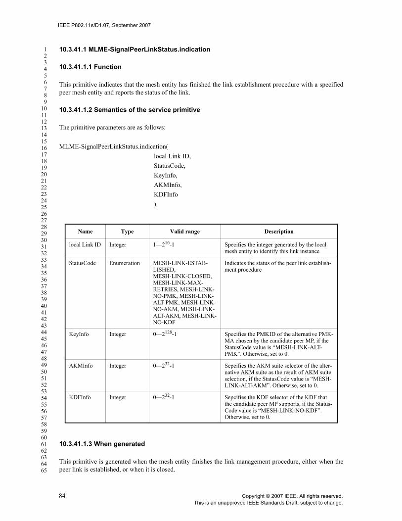
IEEE P802.11s/D1.07, September 2007
123456789
1011121314151617181920212223242526272829303132333435363738394041424344454647484950515253545556575859606162636465
10.3.41.1 MLME-SignalPeerLinkStatus.indication
10.3.41.1.1 Function
This primitive indicates that the mesh entity has finished the link establishment procedure with a specifiedpeer mesh entity and reports the status of the link.
10.3.41.1.2 Semantics of the service primitive
The primitive parameters are as follows:
MLME-SignalPeerLinkStatus.indication(local Link ID,StatusCode,KeyInfo,AKMInfo,KDFInfo)
10.3.41.1.3 When generated
This primitive is generated when the mesh entity finishes the link management procedure, either when thepeer link is established, or when it is closed.
Name Type Valid range Description
local Link ID Integer 1—216-1 Specifies the integer generated by the local mesh entity to identify this link instance
StatusCode Enumeration MESH-LINK-ESTAB-LISHED,MESH-LINK-CLOSED, MESH-LINK-MAX-RETRIES, MESH-LINK-NO-PMK, MESH-LINK-ALT-PMK, MESH-LINK-NO-AKM, MESH-LINK-ALT-AKM, MESH-LINK-NO-KDF
Indicates the status of the peer link establish-ment procedure
KeyInfo Integer 0—2128-1 Specifies the PMKID of the alternative PMK-MA chosen by the candidate peer MP, if the StatusCode value is “MESH-LINK-ALT-PMK”. Otherwise, set to 0.
AKMInfo Integer 0—232-1 Sepcifies the AKM suite selector of the alter-native AKM suite as the result of AKM suite selection, if the StatusCode value is “MESH-LINK-ALT-AKM”. Otherwise, set to 0.
KDFInfo Integer 0—232-1 Sepcifies the KDF selector of the KDF that the candidate peer MP supports, if the Status-Code value is “MESH-LINK-NO-KDF”. Otherwise, set to 0.
84 Copyright © 2007 IEEE. All rights reserved.This is an unapproved IEEE Standards Draft, subject to change.

IEEE P802.11s/D1.07, September 2007
123456789
1011121314151617181920212223242526272829303132333435363738394041424344454647484950515253545556575859606162636465
10.3.41.1.4 Effect of receipt
This primitive enables the mesh entity to handle the link instance status.
10.3.42 CancelPeerLink
This mechanism supports the process of cancelling the link instance with a specified peer mesh entity.
10.3.42.1 MLME-CancelPeerLink.request
10.3.42.1.1 Function
This primitive requests the link instance with a specified peer mesh entity be cancelled.
10.3.42.1.2 Semantics of the service primitive
The primitive parameters are as follows:
MLME-CancelPeerLink.request(local Link ID,ReasonCode)
10.3.42.1.3 When generated
This primitive is generated by the SME to cancel a link instance.
10.3.42.1.4 Effect of receipt
This primitive sets the mesh entity to get ready to close the peer link with the specified peer mesh entity. TheMLME subsequently issues a MLME-CancelPeerLink.confirm to reflect the results.
10.3.42.2 MLME-CancelPeerLink.confirm
10.3.42.2.1 Function
This primitive reports the result of cancel link request.
10.3.42.2.2 Semantics of the service primitive
The primitive parameters are as follows:
MLME-CancelPeerLink.confirm(local Link ID,
Name Type Valid range Description
local Link ID Integer 1—216-1 Specifies the integer generated by the local mesh entity to identify the link instance
ReasonCode Enumeration MESH-MAX-NEIGH-BORS
Reason that the link instance is cancelled.
Copyright © 2007 IEEE. All rights reserved. 85This is an unapproved IEEE Standards Draft, subject to change.

IEEE P802.11s/D1.07, September 2007
123456789
1011121314151617181920212223242526272829303132333435363738394041424344454647484950515253545556575859606162636465
ResultCode)
10.3.42.2.3 When generated
This primitive is generated by the MLME as the result of an MLME-CancelPeerLink.request.
10.3.42.2.4 Effect of receipt
The SME is notified of the results of the cancel link procedure.
10.3.43 MLME-MeshKeyHolderHandshake
The following primitives facilitate the transmission of Mesh Key Holder Security Handshake messages.
10.3.43.1 MLME-MeshKeyHolderHandshake.request
10.3.43.1.1 Function
This primitive requests that the mesh entity send a Mesh Key Holder Security Handshake message to thespecified MP.
10.3.43.1.2 Semantics of the service primitive
The primitive parameters are as follows:
MLME-MeshKeyHolderHandshake.request(PeerMACContent of Mesh Key Holder Handshake frame)
Name Type Valid range Description
local Link ID Integer 1—216-1 Specifies the integer generated by the local mesh entity to identify the link instance
ResultCode Enumeration SUCCESS, FAILURE-NOT-FOUND
Indicates the result of the cancel link request. The result is either success or failure when the link instance is not found.
Name Type Valid range Description
PeerMAC MAC Address Valid individ-ual MAC address
Specifies the address of the peer MAC entity to which the Mesh Key Holder Security frame is to be sent.
Content of Mesh Key Holder Handshake frame
Sequence of octets
As defined in 7.4b.1.1.
The contents of the Mesh Key Holder Hand-shake frame to send to the peer MAC entity.
86 Copyright © 2007 IEEE. All rights reserved.This is an unapproved IEEE Standards Draft, subject to change.

IEEE P802.11s/D1.07, September 2007
123456789
1011121314151617181920212223242526272829303132333435363738394041424344454647484950515253545556575859606162636465
10.3.43.1.3 When generated
This primitive is generated by the SME to request that a Mesh Key Holder Handshake frame be sent to thespecified MP.
10.3.43.1.4 Effect of receipt
On receipt of this primitive, the MLME constructs a Mesh Key Holder Handshake frame containing theinformation specified. The frame is scheduled for transmission.
10.3.43.2 MLME-MeshKeyHolderHandshake.confirm
10.3.43.2.1 Function
This primitive reports the results of a request to send a Mesh Key Holder Security Handshake message.
10.3.43.2.2 Semantics of the service primitive
The primitive parameters are as follows:
MLME-MeshKeyHolderHandshake.confirm(ResultCode)
10.3.43.2.3 When generated
This primitive is generated by the MLME as a result of an MLME-MeshKeyHolderHandshake.request prim-itive.
10.3.43.2.4 Effect of receipt
The SME is notified of the results of the request to send a Mesh Key Holder Handshake frame.
10.3.43.3 MLME-MeshKeyHolderHandshake.indication
10.3.43.3.1 Function
This primitive indicates to the SME that the MLME has received a Mesh Key Holder Handshake frame froma peer MAC entity.
10.3.43.3.2 Semantics of the service primitive
The primitive parameters are as follows:
Name Type Valid range Description
ResultCode Enumeration SUCCESS, INVALID_PARAMETERS, or UNSPECIFIED_FAILURE
Reports the outcome of the request to send a Mesh Key Holder Handshake frame.
Copyright © 2007 IEEE. All rights reserved. 87This is an unapproved IEEE Standards Draft, subject to change.

IEEE P802.11s/D1.07, September 2007
123456789
1011121314151617181920212223242526272829303132333435363738394041424344454647484950515253545556575859606162636465
MLME-MeshKeyHolderHandshake.indication(PeerMACContent of Mesh Key Holder Handshake frame)
10.3.43.3.3 When generated
This primitive is generated by the MLME as a result of the receipt of a Mesh Key Holder Handshake framefrom a peer MAC entity.
10.3.43.3.4 Effect of receipt
The SME is notified of the reception of a Mesh Key Holder Handshake frame, and is provided the contentsof the message.
10.3.44 MLME-MeshKeyTransport
The following primitives facilitate the Mesh Key Transport Protocols.
10.3.44.1 MLME-MeshKeyTransport.request
10.3.44.1.1 Function
This primitive requests that the mesh entity send a Mesh Key Transport Protocol message to the specifiedMP.
10.3.44.1.2 Semantics of the service primitive
The primitive parameters are as follows:
MLME-MeshKeyTransport.request(PeerMACContent of Mesh Key Transport Protocol message)
10.3.44.1.3 When generated
This primitive is generated by the SME to request that a message of a Mesh Key Transport Protocol be sentto the specified MP.
Name Type Valid range Description
PeerMAC MAC Address Valid individ-ual MAC address
Specifies the address of the peer MAC entity from which the Mesh Key Holder Handshake frame was received.
Content of Mesh Key Holder Handshake frame
Sequence of octets
As defined in 7.4b.1.1.
The contents of the Mesh Key Holder Hand-shake frame received from the peer MAC entity.
88 Copyright © 2007 IEEE. All rights reserved.This is an unapproved IEEE Standards Draft, subject to change.

IEEE P802.11s/D1.07, September 2007
123456789
1011121314151617181920212223242526272829303132333435363738394041424344454647484950515253545556575859606162636465
10.3.44.1.4 Effect of receipt
On receipt of this primitive, the MLME constructs a Mesh Action frame containing the information speci-fied. The frame is scheduled for transmission.
10.3.44.2 MLME-MeshKeyTransport.confirm
10.3.44.2.1 Function
This primitive reports the results of a request to send a Mesh Key Transport Protocol message.
10.3.44.2.2 Semantics of the service primitive
The primitive parameters are as follows:
MLME-MeshKeyTransport.confirm(
ResultCode
)
10.3.44.2.3 When generated
This primitive is generated by the MLME as a result of an MLME-MeshKeyTransport.request primitive.
10.3.44.2.4 Effect of receipt
The SME is notified of the results of the Mesh Key Transport Protocol request.
Name Type Valid range Description
PeerMAC MAC Address Valid individ-ual MAC address
Specifies the address of the peer MAC entity to which the Mesh Key Transport Protocol message is to be sent.
Content of Mesh Key Transport Protocol mes-sage
Sequence of octets
As defined in 7.4b.1.2, 7.4b.1.3, 7.4b.1.4, or 7.4b.1.5.
The contents of the PMK-MA Notification, Request, Response, or Delete Mesh Action frame to send to the peer MAC entity.
Name Type Valid range Description
ResultCode Enumeration SUCCESS, INVALID_PARAMETERS, or UNSPECIFIED_FAILURE
Reports the outcome of the request to send a Mesh Key Transport Protocol message.
Copyright © 2007 IEEE. All rights reserved. 89This is an unapproved IEEE Standards Draft, subject to change.

IEEE P802.11s/D1.07, September 2007
123456789
1011121314151617181920212223242526272829303132333435363738394041424344454647484950515253545556575859606162636465
10.3.44.3 MLME-MeshKeyTransport.indication
10.3.44.3.1 Function
This primitive indicates to the SME that the MLME has received a Mesh Key Transport Protocol messagefrom a peer MAC entity.
10.3.44.3.2 Semantics of the service primitive
The primitive parameters are as follows:
MLME-MeshKeyTransport.indication(PeerMACContent of Mesh Key Transport Protocol message)
10.3.44.3.3 When generated
This primitive is generated by the MLME as a result of the receipt of a Mesh Key Transport Protocol mes-sage from a peer MAC entity.
10.3.44.3.4 Effect of receipt
The SME is notified of the reception of a Mesh Key Transport Protocol message, and is provided the con-tents of the message.
10.3.45 MLME-MeshEAPTransport
The following primitives describe how mesh entities manage the transport of EAP messages between meshkey holders, using the Mesh EAP Message Transport Protocol.
10.3.45.1 MLME-MeshEAPTransport.request
10.3.45.1.1 Function
This primitive requests that the mesh entity send a Mesh EAP Encapsulation frame as part of the Mesh EAPMessage Transport Protocol.
Name Type Valid range Description
PeerMAC MAC Address Valid individ-ual MAC address
Specifies the address of the peer MAC entity from which the Mesh Key Transport Protocol message was received.
Content of Mesh Key Transport Protocol mes-sage
Sequence of octets
As defined in 7.4b.1.2, 7.4b.1.3, 7.4b.1.4, or 7.4b.1.5.
The contents of the PMK-MA Notification, Request, Response, or Delete Mesh Action frame received from the peer MAC entity.
90 Copyright © 2007 IEEE. All rights reserved.This is an unapproved IEEE Standards Draft, subject to change.
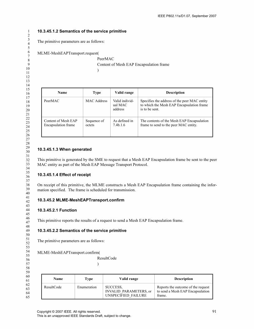
IEEE P802.11s/D1.07, September 2007
123456789
1011121314151617181920212223242526272829303132333435363738394041424344454647484950515253545556575859606162636465
10.3.45.1.2 Semantics of the service primitive
The primitive parameters are as follows:
MLME-MeshEAPTransport.request(PeerMACContent of Mesh EAP Encapsulation frame)
10.3.45.1.3 When generated
This primitive is generated by the SME to request that a Mesh EAP Encapsulation frame be sent to the peerMAC entity as part of the Mesh EAP Message Transport Protocol.
10.3.45.1.4 Effect of receipt
On receipt of this primitive, the MLME constructs a Mesh EAP Encapsulation frame containing the infor-mation specified. The frame is scheduled for transmission.
10.3.45.2 MLME-MeshEAPTransport.confirm
10.3.45.2.1 Function
This primitive reports the results of a request to send a Mesh EAP Encapsulation frame.
10.3.45.2.2 Semantics of the service primitive
The primitive parameters are as follows:
MLME-MeshEAPTransport.confirm(ResultCode)
Name Type Valid range Description
PeerMAC MAC Address Valid individ-ual MAC address
Specifies the address of the peer MAC entity to which the Mesh EAP Encapsulation frame is to be sent.
Content of Mesh EAP Encapsulation frame
Sequence of octets
As defined in 7.4b.1.6
The contents of the Mesh EAP Encapsulation frame to send to the peer MAC entity.
Name Type Valid range Description
ResultCode Enumeration SUCCESS, INVALID_PARAMETERS, or UNSPECIFIED_FAILURE
Reports the outcome of the request to send a Mesh EAP Encapsulation frame.
Copyright © 2007 IEEE. All rights reserved. 91This is an unapproved IEEE Standards Draft, subject to change.

IEEE P802.11s/D1.07, September 2007
123456789
1011121314151617181920212223242526272829303132333435363738394041424344454647484950515253545556575859606162636465
10.3.45.2.3 When generated
This primitive is generated by the MLME as a result of receiving an MLME-MeshEAPTransport.requestprimitive.
10.3.45.2.4 Effect of receipt
The SME is notified of the results of the request to send a Mesh EAP Encapsulation frame.
10.3.45.3 MLME-MeshEAPTransport.indication
10.3.45.3.1 Function
This primitive indicates to the SME that the MLME has received a Mesh EAP Encapsulation frame.
10.3.45.3.2 Semantics of the service primitive
The primitive parameters are as follows:
MLME-MeshEAPTransport.indication(PeerMACContent of Mesh EAP Encapsulation frame)
10.3.46.3.3 When generated
This primitive is generated by the MLME as a result of the receipt of a Mesh EAP Encapsulation frame froma peer MAC entity.
10.3.45.3.3 Effect of receipt
The SME is notified of the reception of a Mesh EAP Encapsulation frame, and is provided the contents ofthe message.
Name Type Valid range Description
PeerMAC MAC Address Valid individ-ual MAC address
Specifies the address of the peer MAC entity from which the Mesh EAP Encapsulation frame was received.
Content of Mesh EAP Encapsulation frame
Sequence of octets
As defined in 7.4b.1.6
The contents of the Mesh EAP Encapsulation frame received from the peer MAC entity.
92 Copyright © 2007 IEEE. All rights reserved.This is an unapproved IEEE Standards Draft, subject to change.
IEEE P802.11s/D1.07, September 2007
123456789
1011121314151617181920212223242526272829303132333435363738394041424344454647484950515253545556575859606162636465
11. MLME
11.3 STA Authentication and Association
Insert new clause 11.3.3 at the end of clause 11.3:
11.3.3 Additional Mechanisms for APs with Mesh Functionality
After the initial state for a non-AP STA with no mesh functionality has been established for authentication /association, the AP with mesh functionality may verify in a timely fashion that the MAC address of the non-AP STA does not belong to another STA with mesh functionality in the mesh network.
If the MAC address of the non-AP STA does already exist in the mesh network, the AP with mesh function-ality will reject the station. Depending on the progress of the authentication / association, the rejected stationwill be disassociated and/or deauthenticated with Status Code "unspecified reason".
The mechanism for verifying disjunct MAC addresses depends on the active path selection protocol andmight be vendor specific. See 11A.8.9 for HWMP.
11.9 DFS procedures
11.9.7 Selecting and advertising a new channel
Insert the following new clause after 11.9.7.2:
EDITORIAL NOTE—clause numbering based on 11y/D2.0 adding 11.9.7.3. The following clause should appear immediately after 11.9.7.2 (i.e., before 11y clause 11.9.7.3)
11.9.7.2aSelecting and advertising a new channel in a mesh
If an MP detects the need to switch the channel of a PHY (e.g., due to regulatory requirement for radaravoidance), the MP shall attempt to inform peer MPs to which a mesh link has been established on the PHYof the need to channel switch.
Once the MP identifies the candidate channel to switch its PHY to, it creates a new candidate channelprecedence indicator value by adding a pseudo-random number to the current channel precedence value. Therandom value shall be in the range 0 to 8191 inclusive. The random value shall be selected in a manner thatminimizes the probability of MPs generating the same number, even when those MPs are subjected to thesame initial conditions. It is important that designers recognize the need for statistical independence amongthe random number streams among MPs.
The MP then executes the UCG switch procedure described in 11A.3.3.
Copyright © 2007 IEEE. All rights reserved. 93This is an unapproved IEEE Standards Draft, subject to change.

IEEE P802.11s/D1.07, September 2007
123456789
1011121314151617181920212223242526272829303132333435363738394041424344454647484950515253545556575859606162636465
Insert the following new clause after 11:
11A. Mesh networking
11A.1 Mesh discovery
11A.1.1 General
Mesh discovery and peer link management require that MPs have sufficient information about themselvesand potential neighbors. This process requires detection of potential mesh neighbors through Beacons orthrough active scanning using Probe Requests. Mesh peer link management is a continuous process thatentails monitoring of neighbors so as to detect and react to changes in connectivity.
11A.1.2 Use of mesh identifier
The Mesh ID is used as a shorthand for a group of MPs that may form a mesh network. A matching Mesh IDis necessary for joining a mesh, along with other required conditions described in 11A.1.4. The Mesh IDmay be installed in mesh capable devices by a variety of means which are beyond the scope of this standard.In the simplest case, the Mesh ID is set by the user, e.g., “Mike’s Mesh”.
NOTE--The Mesh ID is similar in purpose to an SSID, which is used to allow simple STAs to identify can-didate APs with which to associate. SSIDs are used in STA implementations for AP discovery, thus toenable MP-to-MP discovery in a mesh while avoiding confusing non-mesh STAs, a new mesh-specific iden-tifier is specified rather than reusing the existing overloaded SSID identifier. To avoid having STAs sendassociation requests to MPs, a valid SSID should not be included in Beacon frames sent by MPs. To avoidcompatibility issues, rather than removing the SSID information element from MP Beacon frames, the wild-card value is used.
11A.1.3 Profiles for extensibility
An MP shall support at least one mesh profile. A mesh profile consists of:
1. A Mesh ID
2. A path selection protocol identifier
3. A path selection metric identifier
The path selection protocol and path selection metrics in use may be different for different profiles.
11A.1.4 Candidate peer MP discovery
The purpose of this procedure is to discover candidate peer MPs and their properties, covering cases bothbefore and after an MP is a member of a mesh network.
A configured MP, by definition, has at least one mesh profile. If the MP is a member of a mesh, exactly onemesh profile is active.
An MP performs passive or active scanning to discover neighbor MPs. In case of passive scanning, an MPshall be considered a neighbor MP if and only if all of the following conditions are met (a similar mecha-nism with probe response can be used for active scanning):
1. A beacon is received from that MP.
94 Copyright © 2007 IEEE. All rights reserved.This is an unapproved IEEE Standards Draft, subject to change.

IEEE P802.11s/D1.07, September 2007
123456789
1011121314151617181920212223242526272829303132333435363738394041424344454647484950515253545556575859606162636465
2. The received beacon contains a Mesh ID that matches the Mesh ID of the MP’s active mesh profileor that matches the Mesh ID of at least one of the MP’s mesh profiles if the MP is not currently amember of a mesh.
3. The received beacon contains a Mesh Configuration element (see 7.3.2.54) that containsa. A supported version numberb. A path selection protocol identifier and metric identifier matching the MP’s active mesh
profile or matching at least one of the MP’s mesh profiles if the MP is not currently amember of a mesh.
c. A congestion control mode identifier matching the MP's active congestion control modeor matching at least one of the MP's congestion control modes if the MP is not currently amember of a mesh.
A neighbor MP shall also be considered a candidate peer if and only if, in addition:
4. The beacon contains an Mesh Configuration element (see 7.3.2.54) with the “Accepting PeerLinks” field set to 1.
The MP attempts to discover all neighbor and candidate peer MPs, and maintains the neighbor MPinformation indicating the MAC address of each MP, the most recently observed link state parameters, thereceived channel number and state.
If an MP is unable to detect neighbor MPs, it may adopt a Mesh ID from one of its mesh profiles, andproceed to the active state. This may occur, for example, when the MP is the first MP to power on (ormultiple MPs power on simultaneously). Peer MP links are established later as part of the continuous meshpeer link management procedures.
Note--Identification of candidate peer MPs with whom to form links is out side the scope of this standard.
11A.2 Mesh peer link management
11A.2.1 Overview
The Mesh Peer Link Management protocol is used to establish and close peer links between MPs. 11A.2.3specifies the protocol details. The following summarizes the protocol operations.
MPs shall not transmit data frames or management frames other than the ones used for discovery and peerlink management until the peer link has been established.
An MP shall be able to establish at least one mesh link with a peer MP, and may be able to establish manysuch links simultaneously, if the maximum number of peer MPs is not reached. The procedure of choosing acandidate peer MP from a set of neighbor MPs to establish a mesh link is specified in 11A.1.4.
MP peer link management uses link instances. A link instance is a logical entity that the MP uses to handle apeer link or an attempt of establishing a peer link. Its behavior is governed by a peer link management finitestate machine defined in 11A.2.3.
The MP shall identify a link instance with the peer MP. The link instance identifier is defined as <local-MAC, peerMAC, localLinkID, peerLinkID>. localMAC is the MAC address of the MP. peerMAC is theMAC address of the peer MP or the candidate peer MP. localLinkID is an integer generated by the MP. peer-LinkID is an integer generated by the peer MP or the candidate peer MP. The localLinkID shall be uniqueamong all link identifiers used by the MP for its current mesh link instances. The MP selects the localLinkIDto provide high assurance that the same number has not been used to identify a recent link instance. The
Copyright © 2007 IEEE. All rights reserved. 95This is an unapproved IEEE Standards Draft, subject to change.

IEEE P802.11s/D1.07, September 2007
123456789
1011121314151617181920212223242526272829303132333435363738394041424344454647484950515253545556575859606162636465
peerLinkID shall be supplied by the peer MP or candidate peer MP in Peer Link Open and Confirm frames.The link identifiers are transmitted via peer link management frames.
The MP shall keep information of link instance identifier and the respective policy as the link state of thelink instance. The actual method of handling the link state is out of the scope this specification.
The MP shall start the peer link management protocol in either of the following two cases. In case one, theIEEE 802.11 SME instructs the MP to passively listen to incoming requests from candidate peer MPs. TheSME issues the MLME-PassivePeerLinkOpen.request(localLinkID) primitive to create a finite statemachine to handle peer link establishment attempts initiated by other MPs. The MP shall issue the MLME-PassivePeerLinkOpen.confirm(localLinkID) primitive to inform the completion of creating the finite statemachine. The localLinkID identifies the link instance.
The SME issues a MLME-ActivePeerLinkOpen.request(peerMAC, localLinkID) primitive to create aninstance of a finite state machine establishing a link with the candidate peer MP whose MAC address ispeerMAC. The MP shall issue the MLME-ActivePeerLinkOpen.confirm(peerMAC, localLinkID) primitiveto inform the completion of creating the finite state machine.
A link instance ends when the peer link is closed. The link close can be caused by either an internal event oran external event. The specification of internal events is beyond the scope of this standard.
The IEEE 802.11 SME can close the link instance identified by the instance identifier localLinkID by issu-ing the MLME-CancelPeerLink.request(localLinkID, ReasonCode) primitive. The MP shall issue MLME-CancelPeerLink.confirm(localLinkID, ResultCode) to inform the SME the completion of closing the link.Upon closing the link completely, the MP shall issue the MLME-SignalPeerLinkStatus.indication(localL-inkID, statusCode) primitive to report the result of the close.
Receiving of a correct Peer Link Close frame or a failure of processing the incoming peer link managementframe shall close the link instance. Such events are external events.
The behavioral details of closing a link instance are specified in 11A.2.3.
The MP uses the peer link management frames to manage a link instance.
A Peer Link Open frame requests that a mesh link instance be established between the Peer Link Opensender and the receiver. The MP shall send a Peer Link Confirm frame in response to the Peer Link Openframe if the link instance proceeds with the protocol. The Peer Link Close frame is used to inform thereceiver to close the mesh peer link. The protocol succeeds in establishing a mesh link when the followingrequirements are satisfied: 1) both MPs have sent and received (and correctly processed) a Peer Link Openframe regarding this mesh link; 2) both MPs have sent and received (and correctly processed) a correspond-ing Peer Link Confirm frame regarding this mesh link.
The protocol has a retry mechanism. The retryTimer controls the maximum time the link instance waits for aPeer Link Confirm frame responding to any Peer Link Open frame the link instance has sent. The MP setsthe retryTimer when it sends a Peer Link Open frame. If the MP does not receive a corresponding Peer LinkConfirm frame before the retryTimer expires, the link instance shall retry the request by sending the samePeer Link Open frame. The MP shall clear the retryTimer when it receives a corresponding Peer Link Con-firm frame or when the link instance is closed. If the MP does not receive a Peer Link Confirm frame afterre-sending the Peer Link Open frame for dot11MeshMaxRetries times, the MP shall abort the attemptto establish a peer link instance with the candidate peer MP. The retryCounter is a variable in link state thatkeeps record of the number of Peer Link Open frames been re-sent for the link instance. It is initiated to zerowhen the first Peer Link Open frame is sent out for the link instance.
96 Copyright © 2007 IEEE. All rights reserved.This is an unapproved IEEE Standards Draft, subject to change.

IEEE P802.11s/D1.07, September 2007
123456789
1011121314151617181920212223242526272829303132333435363738394041424344454647484950515253545556575859606162636465
The protocol defines a confirmTimer to bound the time that the MP waits for a Peer Link Open frame afterreceiving a Peer Link Confirm frame. The MP sets the confirmTimer when the Peer Link Confirm frame isreceived but the corresponding Peer Link Open frame has not. If the Peer Link Open frame is not receivedwhen confirmTimer expires, the MP shall abort the attempt to establish a peer link with the candidate peerMP and send a Peer Link Close frame to close the link instance.
The protocol shall set the holdingTimer when the MP sends the first Peer Link Close frame for the linkinstance; this timer provides a grace period that prevents deadlock or livelock. Before the holdingTimerexpires, the link instance shall respond to the incoming Peer Link Open frames associated with the linkinstance by sending the Peer Link Close frame. When the holdingTimer expires, the MP shall terminate thelink instance completely and issue MLME-SignalPeerLinkStatus.indication(localLinkID, MESH-LINK-CLOSED) primitive to inform the IEEE 802.11 SME the result of the close.
11A.2.2 Processing Peer Link Management Frames
11A.2.2.1 Overview
The MP shall classify the incoming peer link management frames to decide either to accept, reject, orsilently ignore the frame. If the frame contains a broadcast/multicast address in TA, it shall be silentlyignored. The result of frame processing shall trigger an event accordingly (see 11A.2.3.2). The mechanismthat is used to classify frames is beyond the scope of this standard.
The MP shall verify the link instance identifier in a peer link management frame determining whether theidentifier identifies a known link instance, fails to match any instance, or is incomplete. The rules for verify-ing instance identifier are frame specific; see 11A.2.2.2, 11A.2.2.3, and 11A.2.2.4.
The MP shall also verify the configuration parameters, if present, conveyed in the Open and Confirmframes. The Mesh Configuration information element and Frame Control field supply the configurationparameters. If either is present in the Confirm, the MP shall verify that the parameters reported by the Candi-date peer MP match those the MP has agreed to use for this link instance. In particular, the MP shall verifythe following fields or subfields. This verification is needed to satisfy the consistency property, i.e., to guar-antee that MPs agree on the configuration before establishing a mesh link.
a) Fields in Mesh Configuration element1) Active Path Selection Protocol ID field2) Active Path Selection Metric ID field3) Mesh Capability field, including the following subfields
•Accepting Peer Links•Power Save Support Enabled•Synchronization Enabled•Synchronization Active•Synchronization Support Required from Peer•MDA Enabled
b) Frame Control field1) Power Management field
MPs shall verify that the same Path Selection Protocol and the same Path Selection Metric are used.
The MP shall verify that it supports power save support services when the candidate peer MP sets the PowerManagement field of the Frame Control field to 1.
The MP shall verify that the candidate peer MP supports power save support when the MP intends to operatein Power Save mode.
Copyright © 2007 IEEE. All rights reserved. 97This is an unapproved IEEE Standards Draft, subject to change.

IEEE P802.11s/D1.07, September 2007
123456789
1011121314151617181920212223242526272829303132333435363738394041424344454647484950515253545556575859606162636465
The MP shall verify that it supports synchronization services when the candidate peer MP sets the “Synchro-nization Support Required from Peer” field to 1.
The MP shall verify that it supports MDA services when the candidate peer MP sets the “MDA Enabled”field to 1.
The MP shall ignore all security related parameters if the RSN information element is not present.
11A.2.2.2 Process Peer Link Close frames
The CLS_IGNR event shall be triggered if the Peer Link Close frame contains a mismatched instance iden-tifier or an incomplete instance identifier.
A received instance identifier is a mismatch if:— the locally recorded peerLinkID exists and it does not match the value in the Local Link ID field in
the frame, or— the frame carries a non-zero value in the Peer Link ID field of the frame, but the value does not
match the local record of localLinkID.
The received instance identifier is incomplete if the value of the Peer Link ID field is zero.
In other cases, the CLS_ACPT event shall be triggered.
11A.2.2.3 Process Peer Link Open frames
The OPN_RJCT event shall be triggered if the Peer Link Open frame contains an unacceptable or erroneousconfiguration parameter (see 11A.2.2.1) or the value of a configuration parameter (see 11A.2.2.1) is not thesame as the value in either a Peer Link Open frame or a Peer Link Confirm frame received earlier whenestablishing the link instance.
The OPN_IGNR event shall be triggered if the Peer Link Open frame contains a mismatched instance iden-tifier.
If the MP has local information of peerLinkID and the value does not match the value in the Local Link IDfield of the Peer Link Open frame, the instance identifier is a mismatch.
In other cases, the OPN_ACPT event shall be triggered. The link state is updated to include the link instanceidentifier and other information from Mesh Configuration element.
11A.2.2.4 Process Peer Link Confirm frames
The CNF_RJCT event shall be triggered if the Peer Link Confirm frame contains an unacceptable or errone-ous configuration parameter (see 11A.2.2.1) or the value of a configuration parameter (see 11A.2.2.1) is notthe same as the value from a frame (either a Peer Link Open frame or a Peer Link Confirm frame) receivedearlier during the link instance establishment attempt.
The CNF_IGNR event shall be triggered if the Peer Link Confirm frame contains a mismatched instanceidentifier.
The instance identifier in the frame is a mismatch if:— the value in the Peer Link ID field of the frame does not match the local state of localLinkID. — the value in the Local Link ID field of the frame does not match the local state of peerLinkID,
excluding the case that the peerLinkID value is unknown.
98 Copyright © 2007 IEEE. All rights reserved.This is an unapproved IEEE Standards Draft, subject to change.

IEEE P802.11s/D1.07, September 2007
123456789
1011121314151617181920212223242526272829303132333435363738394041424344454647484950515253545556575859606162636465
In other cases, the CNF_ACPT event shall be triggered. The link state is updated to include the link instanceidentifier and other information from Mesh Configuration element.
11A.2.3 Finite State Machine
11A.2.3.1 States
The finite state machine uses the following seven states:a) IDLE – In the IDLE state, the finite state machine only responses to events generated by IEEE
802.11 SME (see 11A.2.3.2). Other types of events are silently ignored. IDLE state is a terminalstate. The IDLE state is for explanatory purpose, which enables complete specification of the finitestate machine to avoid deadlock and livelock. It is not mandatory to implement the IDLE state.
b) LISTEN – In the LISTEN state, the finite state machine is passively listening for an incoming PeerLink Open frame from a candidate peer MP.
c) OPN_SNT – In the OPN_SNT state, the finite state machine has actively sent a Peer Link Openframe and is waiting for the incoming Peer Link Open and Peer Link Confirm frames from the can-didate peer MP.
d) CNF_RCVD – In the CNF_RCVD state, the finite state machine has received a Peer Link Confirmframe, but has not received a Peer Link Open frame; therefore the MP has not sent the correspondingPeer Link Confirm frame.
e) OPN_RCVD – In the OPN_RCVD state, the finite state machine has received only the Peer LinkOpen frame but not the Peer Link Confirm. The MP has also sent a Peer Link Confirm frame uponreceiving a Peer Link Open frame.
f) ESTAB – In the ESTAB state, the finite state machine has received both the Peer Link Open andPeer Link Confirm frames. The MP has also sent both the Peer Link Open frame and Peer Link Con-firm frame. The link is established and configured for exchanging frames with peer MPs in theESTAB state.
g) HOLDING − In the HOLDING state, the finite state machine is closing the link with the peer MP orthe candidate peer MP.
11A.2.3.2 Events and Actions
The finite state machine uses three types of events: events created by IEEE 802.11 SME, external eventsgenerated by frame processing, and events associated internal timers.
IEEE 802.11 SME uses the following primitives to pass events to the finite state machine.a) CNCL -- MLME-CancelPeerLink.request(localLinkID, ReasonCode) event is used to instruct the
link instance to cancel the link with the peer MP. The link instance uses MLME-CancelPeer-Link.confirm(localLinkID, ResultCode) primitive to return the result to IEEE 802.11 SME.
b) PASOPN -- MLME-PassivePeerLinkOpen.request event is used to instruct the link instance to pas-sively listen to a peer link establishment frame from a candidate peer MP. The link instance usesMLME-PassivePeerLinkOpen.confirm(localLinkID) to return the result to IEEE 802.11 SME.
c) ACTOPN -- MLME-ActivePeerLinkOpen.request(peerMAC) event is used to instruct the linkinstance to actively initiate the peer link establishment with the candidate peer MP whose MACaddress is peerMAC. The link instance uses MLME-ActivePeerLinkOpen.confirm(peerMAC,localLinkID) primitive to return the result to IEEE 802.11 SME.
The events generated by frame processing area) CLS_ACPT -- PeerLinkClose_Accept(peerMAC, localLinkID, peerLinkID, reasonCode) event
indicates that a Peer Link Close frame meeting the correctness criteria of 11A.2.2.2 has been
Copyright © 2007 IEEE. All rights reserved. 99This is an unapproved IEEE Standards Draft, subject to change.

IEEE P802.11s/D1.07, September 2007
123456789
1011121314151617181920212223242526272829303132333435363738394041424344454647484950515253545556575859606162636465
received from peerMAC for the link instance identified by localLinkID and peerLinkID. The rea-sonCode specifies the reason that causes the generation of the Peer Link Close frame.
b) CLS_IGNR -- PeerLinkClose_Ignore(peerMAC, localLinkID, peerLinkID) event indicates that aPeer Link Close frame with mis-matched link identifiers, as specified in 11A.2.2.2, has beenreceived from peerMAC for the link instance identified by localLinkID and peerLinkID.
c) OPN_ACPT -- PeerLinkOpen_Accept(peerMAC, peerLinkID, Configuration) event indicates that aPeer Link Open frame meeting the correctness criteria of 11A.2.2.3 has been received frompeerMAC for the link instance identified by localLinkID and peerLinkID. The Configuration is theset of information received in the Mesh Configuration information element.
d) OPN_IGNR -- PeerLinkOpen_Ignore(peerMAC, peerLinkID) event indicates that a Peer Link Openframe with mismatched link identifiers, as specified in 11A.2.2.3, has been received from peerMACfor the link instance identified by locakLinkID and peerLinkID.
e) OPN_RJCT -- PeerLinkOpen_Reject(peerMAC, peerLinkID, Configuration, ReasonCode) eventindicates that a Peer Link Open frame with an invalid Configuration field, as specified in 11A.2.2.3,has been received from peerMAC for the link instance identified by localLinkID and peerLinkID.The Configuration is the set of information as received from Mesh Configuration element. The Rea-sonCode is set to MESH-CONFIGURATION-POLICY-VIOLATION.
f) CNF_ACPT -- PeerLinkConfirm_Accept(peerMAC, localLinkID, peerLinkID, Configuration)event indicates that a Peer Link Confirm frame meeting the correctness criteria of 11A.2.2.4 hasbeen received from peerMAC for the link instance identified by localLinkID and peerLinkID. TheConfiguration is the set of information as received from Mesh Configuration element.
g) CNF_IGNR -- PeerLinkConfirm_Ignore(peerMAC, localLinkID, peerLinkID) event indicates that aPeer Link Confirm frame with mis-matched link identifiers, as specified in 11A.2.2.4, has beenreceived from peerMAC for the link instance identified by localLinkID and peerLinkID.
h) CNF_RJCT -- PeerLinkConfirm_Reject(peerMAC, localLinkID, peerLinkID, Configuration, Rea-sonCode) event indicates that a Peer Link Confirm frame with an invalid Configuration fields, asspecified in 11A.2.2.4, has been received from peerMAC for the link instance identified by localL-inkID and peerLinkID. The Configuration is the set of information as received from Mesh Configu-ration element. The ReasonCode is set to MESH-CONFIGURATION-POLICY-VIOLATION. Thisevent is denoted as.
The internal events are as follows. The term Timeout(localLinkID, item) represents a timeout identifiedlocally by item, for the link instance identified by localLinkID. Three types of timers are used by the finitestate machine. The retryTimer triggers a re-send of the Peer Link Open frame when a Peer Link Confirmframe was not received as a response.
a) TOR1 – This event refers to Timeout(localLinkID, retryTimer) and the dot11MeshMaxRetrieshas not been reached. The state machine shall resend the Peer Link Open frame.
b) TOR2 – This event refers to Timeout(localLinkID, retryTimer) and the dot11MESHMaxRetrieshas been reached. The link instance shall be closed when TOR2 occurs.
c) TOC – The Timeout(localLinkID, confirmTimer) event. The confirmTimer aborts a link establish-ment attempt if a Peer Link Open frame never arrives after receiving the Peer Link Confirm frame.TOC event occurs, the link instance shall be closed.
d) TOH event – The Timeout(localLinkID, holdingTimer) event. The holdingTimer allows a graceperiod for closing the link instance; it is necessary to avoid deadlocks and livelocks that arise due tointeractions between link establishment and termination. When TOH occurs, the link instance shallbe closed completely and the finite state machine shall transition to IDLE state.
The finite state machine may take an action triggered by an event. It uses two types of actions: sending a peer link management frame and handling a timer.
Actions related to sending a peer link management frame:
100 Copyright © 2007 IEEE. All rights reserved.This is an unapproved IEEE Standards Draft, subject to change.

IEEE P802.11s/D1.07, September 2007
123456789
1011121314151617181920212223242526272829303132333435363738394041424344454647484950515253545556575859606162636465
a) sndOPN -- The sendOpen(peerMAC, localLinkID, Configuration) is the action that the link instancetakes to send a Peer Link Open frame to the candidate peer MP, whose MAC address is peerMAC.The frame shall carry localLinkID and the supported Mesh Configuration, as specified as Configura-tion.
b) sndCNF -- The sendConfirm(peerMAC, localLinkID, peerLinkID, Configuration) is the action thatthe link instance takes to send a Peer Link Confirm frame to the candidate peer MP, whose MACaddress is peerMAC. The frame shall carry localLinkID, peerLinkID, and the supported Mesh Con-figuration, as specified as Configuration.
c) sndCLS -- The sendClose(peerMAC, localLinkID, peerLinkID, reasonCode) is the action that thelink instance takes to send a Peer Link Close frame to the peer MP or candidate peer MP, whoseMAC address is peerMAC. The frame shall carry localLinkID and peerLinkID. If the peerLinkID isunknown, it shall be set to zero. The reasonCode shall specify the reason that the Peer Link Close issent, whose value shall be set to a value between 46 to 51 as specified in Table 7-22.
The actions on handling timers are setTimer(localLinkID, item, value) and clearTimer(localLinkID, item).
a) The setTimer(localLinkID, item, timeout) action sets the timeout value specified by timeout to thetimer specified by item. This action only sets the timer for one time for the link instance identifiedby localLinkID. When the timeout time has passed, the timer expires and the event Timeout(localL-inkID, item) is triggered, after which the timer is no longer in effect.
The corresponding actions are denoted as setR, setC, setH, for timer retryTimer, confirmTimer,holdingTimer respectively.
Before setting the retryTimer, the finite state machine shall apply the default link open request back-off algorithm to compute the updated timeout value as the following:
timeout = return timeout + (getRandom mod timeout),
where getRandom routine generates a random value. The initial value of timeout shall be set todot11MeshRetryTimeout. This function statistically increases the length of time for each PeerLink Open retry by 50%. The backoff was inserted into the design to recover from a “gold rush”,which could happen if several already-linked MPs simultaneously detected a new MP trying to enterthe mesh network.
b) The clearTimer(localLinkID, item) action clears the timer item for the link instance identified bylocalLinkID. The corresponding actions are denoted as clR, clC, clH, for timer retryTimer, confirm-Timer, holdingTimer respectively.
NOTE -- The value of dot11MeshMaxRetries is under study. If zero is the appropriate value, the back-off algorithm is not need and will be removed.
11A.2.3.3 State transitions
Table s45 and Figure s55 summarize the state transitions for the peer link management protocol.
In Table s45, each row represents state transitions from the state to all other states. The blank entry meansimpossible transition.
Copyright © 2007 IEEE. All rights reserved. 101This is an unapproved IEEE Standards Draft, subject to change.

IEEE P802.11s/D1.07, September 2007
123456789
1011121314151617181920212223242526272829303132333435363738394041424344454647484950515253545556575859606162636465
Table s45—Peer Link Management Finite State Machine
To State
IDLE LISTEN OPN_SNT CNF_RCVD OPN_RCVD ESTAB HOLDING
From
Sta
te
IDLE PASOPN/ -- ACTOPN/ (sndOPN,
setR)
LISTEN CNCL / -- ACTOPN/ (sndOPN,
setR)
OPN_ACPT/ (sndOPN, snd-
CNF, setR)
OPN_SNT TOR1/ (sndOPN,
setR)
CNF_ACPT/ (clR, setC)
OPN_ACPT/ (sndCNF)
CLS_ACPT, OPN_RJCT, CNF_RJCT,
TOR2, CNCL/ (sndCLS, clR,
setH)
CNF_RCVD CNF_ACPT / --
OPN_ACPT / (clC, sndCNF)
CLS_ACPT, OPN_RJCT, CNF_RJCT, CNCL/ (snd-
CLS, clC, setH)
TOC / (snd-CLS, setH)
OPN_RCVD TOR1 / (sndOPN,
setR)
CNF_ACPT / clR
CLS_ACPT, OPN_RJCT,
CNF_RJCT,TOR2, CNCL/ (sndCLS, clR,
setH)
ESTAB OPN_ACPT / sndCNF
CLS_ACPT, OPN_RJCT,
CNF_RJCT,CNCL/ (snd-CLS, setH)
HOLDING TOH, CLS_ACPT / -
-
OPN_ACPT, CNF_ACPT, OPN_RJCT, CNF_RJCT/
sndCLS
102 Copyright © 2007 IEEE. All rights reserved.This is an unapproved IEEE Standards Draft, subject to change.

IEEE P802.11s/D1.07, September 2007
123456789
1011121314151617181920212223242526272829303132333435363738394041424344454647484950515253545556575859606162636465
In Figure s55, each arrow represents a state transition. All other events not shown in Figure s55 indicatesthat no action causes the state transition.
Figure s55—Finite State Machine of Peer Link Management Protocol
IDLE
LISTEN
OPN_SNTOPN_RCVD
CNF_RCVDESTAB
HOLDING
PASO
PN/--
CNC
L/--
ACTOPN / (sndOPN, setR)
ACTOPN / (sndOPN, setR)
OPN_ACPT /
(snd
OPN,
sndC
NF, se
tR)
TOR1 / (sndOPN, setR)
CNF_ACPT / (clR, setC)
OPN_ACPT / sndCNF
CLS_ACPT, OPN_RJCT, CNF_RJCT,
TOR2, CNCL / (sndCLS, clR,
setH)
CNF_ACPT / --
OPN_ACPT / (clC, sndCNF)
TOC
/ (sn
dCL S
, set
H)
CLS_
ACPt
, OPN
_RJC
T, C
NF_R
JCT,
CNC
L /
(sndC
LS, c
lC, s
etH)
TOR1 / (sndOPN, setR)
CNF_ACPT / clR
CLS_ACPT, OPN_RJCT, CNF_RJCT,
TOR2, CNCL / (sndCLS, clR,
setH)
OPN_ACPT / sndCNF
CLS_ACPT, OPN_RJCT, CNF_RJCT, CNCL /
(sndCLS, setH)
TOH, CLS_ACPT / --
OPN_ACPT,CNF_ACPT,OPN_RJCT,CNF_RJCT
/ sndCLS
IDLE
ESTAB
Copyright © 2007 IEEE. All rights reserved. 103This is an unapproved IEEE Standards Draft, subject to change.

IEEE P802.11s/D1.07, September 2007
123456789
1011121314151617181920212223242526272829303132333435363738394041424344454647484950515253545556575859606162636465
The event/action representation is defined as the following. “E/A” string represents that the action A is takengiven that the event E occurs. “E1, E2/A” string represents that the action A is taken given that the event E1or event E2 occurs. “E/(A1, A2)” string represents that the action A1 and A2 are taken at a time when eventE occurs.
Note that Table s45 and Figure s55 are used for illustration purpose. The protocol behavior is in the follow-ing subclauses.
11A.2.3.4 IDLE state
In the IDLE state the state machine shall not respond to incoming frames from a candidate peer MP.
When PASOPN event occurs, the link instance shall record information in Configuration, generate a newlink identifier localLinkID, initiate the retryCounter to zero, and begin listening for a Link Open frame. Thelink instance shall issue MLME-PassivePeerLinkOpen.confirm(localLinkID) to return the result to IEEE802.11 SME. The finite state machine transitions to LISTEN state.
When ACTOPN event occurs, The link instance shall encode the link information in the Mesh Configura-tion element, generate a new link identifier localLinkID, initiate the retryCounter to zero, and send a PeerLink Open frame to the candidate peer MP whose address is peerMAC. The retryTimer is set according toretryTimeout. The MP uses MLME-ActivePeerLinkOpen.confirm(peerMAC, localLinkID) to return theresult to IEEE 802.11 SME. The finite state machine transitions to OPEN_SENT state.
All other events shall be ignored in this state.
11A.2.3.5 LISTEN state
In the LISTEN state, the link instance waits for unsolicited Link Open frames.
When a CNCL event occurs, the state machine transitions to IDLE state. The link instance shall use theMLME-SignalPeerLinkStatus.indication(localLinkID, MESH-LINK-CLOSED) primitive to report theresult to the IEEE 802.11 SME.
When an ACTOPN event occurs, the link instance shall send a Peer Link Open frame to the candidate peerMP identified by peerMAC. The Peer Link Open frame shall contain the localLinkID and Mesh Configura-tion information. The retryTimer is set according to dot11MeshRetryTimeout. The finite statemachine transitions to OPEN_SENT state.
When a CLS_ACPT event occurs, the finite state machine transitions to IDLE state. The link instance shalluse the MLME-SignalPeerLinkStatus.indication(localLinkID, MESH-LINK-CLOSED) primitive to reportthe result to the IEEE 802.11 SME.
When an OPN_ACPT event occurs, the link instance shall send the corresponding Peer Link Confirm frameto respond to the Peer Link Open frame. And it shall send a Peer Link Open frame to request a Peer LinkConfirm frame from the candidate peer MP. The retryTimer is set according todot11MeshRetryTimeout value. The finite state machine transitions to OPEN_RCVD state.
All other events shall be ignored in this state.
11A.2.3.6 OPEN_SENT state
In the OPEN_SENT state, the link instance waits for a Peer Link Confirm frame. In this state, the retryTimeris set.
104 Copyright © 2007 IEEE. All rights reserved.This is an unapproved IEEE Standards Draft, subject to change.

IEEE P802.11s/D1.07, September 2007
123456789
1011121314151617181920212223242526272829303132333435363738394041424344454647484950515253545556575859606162636465
When a CNCL event occurs, the MP shall clear the retryTimer, send a Peer Link Close frame with reasoncode MESH-LINK-CANCELLED, and set the holdingTimer according to the value ofdot11MeshHoldingTimeout. The finite state machine transitions to HOLDING state.
When a CLS_ACPT event occurs, the MP shall clear the retryTimer, send a Peer Link Close frame with rea-son code MESH-CLOSE-RCVD, and set the holdingTimer according to the value ofdot11MeshHoldingTimeout. The finite state machine transitions to HOLDING state.
When an OPN_ACPT event occurs, the MP shall send the corresponding Peer Link Confirm frame torespond to the incoming Peer Link Open frame. The finite state machine transitions to OPN_RCVD state.Note that the retryTimer is still in effect after the state transition.
When an OPN_RJCT event occurs, the MP shall clear the retryTimer, send a Peer Link Close frame withreason code specified by the OPN_RJCT event, and set the holdingTimer according to the value ofdot11MeshHoldingTimeout. The finite state machine transitions to HOLDING state.
When a CNF_ACPT event occurs, the MP shall clear the retryTimer and shall set the confirmTimer accord-ing to the value of dot11MeshConfirmTimeout and the finite state machine transitions to CNF_RCVDstate.
When a CNF_RJCT event occurs, the MP shall clear the retryTimer, send a Peer Link Close frame with rea-son code specified by the CNF_RJCT event, and set the holdingTimer according to the value ofdot11MeshHoldingTimeout. The finite state machine transitions to HOLDING state.
When a TOR1 event occurs, the Peer Link Open frame shall be resent and the retryCounter shall be incre-mented. The retryTimer shall be set according to the updated retryTimeout computed by the backoff algo-rithm. No state transition occurs.
When a TOR2 event occurs, the MP shall send a Peer Link Close frame with reason code MESH-MAX-RETRIES. The holdingTimer shall be set according to the value of dot11MeshHoldingTimeout, andthe finite state machine transitions to HOLDING state.
All other events shall be ignored in this state.
11A.2.3.7 CNF_RCVD state
In the CNF_RCVD state, the link instance has received a Peer Link Confirm frame and is waiting for a PeerLink Open frame.
When a CNCL event occurs, the MP shall clear the confirmTimer, send a Peer Link Close frame with thereason code MESH-LINK-CANCELLED, and set the holdingTimer according to the value ofdot11MeshHoldingTimeout. The finite state machine transitions to HOLDING state.
When a CLS_ACPT event occurs, the MP shall clear the confirmTimer, send a Peer Link Close frame withreason code MESH-CLOSE-RCVD, and set the holdingTimer according to the value ofdot11MeshHoldingTimeout. The finite state machine transitions to HOLDING state.
When an OPN_ACPT event occurs, the MP shall clear the confirmTimer and shall send the correspondingPeer Link Confirm frame to respond to the incoming Peer Link Open frame. The finite state machine transi-tions to ESTAB state. The link instance shall use the MLME-SignalPeerLinkStatus.indication(localLinkID,MESH-LINK-ESTABLISHED) primitive to report the result to the IEEE 802.11 SME.
Copyright © 2007 IEEE. All rights reserved. 105This is an unapproved IEEE Standards Draft, subject to change.

IEEE P802.11s/D1.07, September 2007
123456789
1011121314151617181920212223242526272829303132333435363738394041424344454647484950515253545556575859606162636465
When an OPN_RJCT event occurs, the MP shall clear the confirmTimer, send a Peer Link Close frame withreason code as specified by the OPN_RJCT event, and set the holdingTimer according to the value ofdot11MeshHoldingTimeout. The finite state machine transitions to HOLDING state.
When a CNF_RJCT event occurs, the MP shall clear the confirmTimer, send a Peer Link Close frame withreason code as specified by the CNF_RJCT event, and set the holdingTimer according to the value ofdot11MeshHoldingTimeout. The finite state machine transitions to HOLDING state.
When TOC event occurs, the MP shall send a Peer Link Close frame with reason code MESH-CONFIRM-TIMEOUT and set the holdingTimer according to the value of dot11MeshHoldingTimeout. The finitestate machine transitions to HOLDING state.
All other events shall be ignored in this state.
11A.2.3.8 OPEN_RCVD state
In the OPEN_RCVD state, the link instance has received a Peer Link Open frame and sent a Peer Link Openframe and the corresponding Peer Link Confirm frame. An incoming Peer Link Confirm is expected.
When a CNCL event occurs, the MP shall clear the retryTimer, send a Peer Link Close frame with reasoncode MESH-LINK-CANCELLED, and set the holdingTimer according to the value ofdot11MeshHoldingTimeout. The finite state machine transitions to HOLDING state.
When a CLS_ACPT event occurs, the MP shall clear the retryTimer, send a Peer Link Close frame, and setthe holdingTimer according to the value of dot11MeshHoldingTimeout. The finite state machine tran-sitions to HOLDING state.
When an OPN_ACPT event occurs, the MP shall resend the corresponding Peer Link Confirm frame. Nostate transition occurs.
When an OPN_RJCT event occurs, the MP shall clear the retryTimer, send a Peer Link Close frame withreason code as specified by the OPN_RJCT event, and set the holdingTimer according to the value ofdot11MeshHoldingTimeout. The finite state machine transitions to HOLDING state.
When a CNF_ACPT event occurs, the retryTimer shall be cleared. The finite state machine transitions toESTAB state. The MP invokes the MLME-SignalPeerLinkStatus.indication(localLinkID, MESH-LINK-ESTABLISHED) to report the result to the IEEE 802.11 SME.
When a CNF_RJCT event occurs, the MP shall clear the retryTimer, send a Peer Link Close frame with rea-son code as specified by the CNF_RJCT event, and set the holdingTimer according to the value ofdot11MeshHoldingTimeout. The finite state machine transitions to HOLDING state.
When a TOR1 event occurs, the Peer Link Open frame shall be resent and the retryCounter shall be incre-mented. The retryTimer shall be set according to the updated retryTimeout computed by the backoff algo-rithm. No state transition occurs.
When a TOR2 event occurs, the MP shall send a Peer Link Close frame with reason code MESH-MAX-RETRIES. The holdingTimer shall be set according to the value of dot11MeshHoldingTimeout, andthe finite state machine transitions to HOLDING state.
All other events shall be ignored in this state.
106 Copyright © 2007 IEEE. All rights reserved.This is an unapproved IEEE Standards Draft, subject to change.

IEEE P802.11s/D1.07, September 2007
123456789
1011121314151617181920212223242526272829303132333435363738394041424344454647484950515253545556575859606162636465
11A.2.3.9 ESTAB state
In the ESTAB state, the link instance has been successfully established with the peer MP.
When a CNCL event occurs, the MP shall send a Peer Link Close frame with reason code MESH-LINK-CANCELLED, and set the holdingTimer according to the value of dot11MeshHoldingTimeout. Thefinite state machine transitions to HOLDING state.
When a CLS_ACPT event occurs, the MP shall send a Peer Link Close frame with reason code MESH-CLOSE-RCVD, and set the holdingTimer according to the value of dot11MeshHoldingTimeout. Thefinite state machine transitions to HOLDING state.
When an OPN_ACPT event occurs, the MP shall respond again by resending the corresponding Peer LinkConfirm frame. No state transition occurs.
All other events shall be ignored in this state.
11A.2.3.10 HOLDING state
In HOLDING state, the MP is closing the link. The holdingTimer is in effect.
When a CLS_ACPT event occurs, the primitive MLME-SignalPeerLinkStatus.indication(localLinkID,MESH-LINK-CLOSED) shall be used to report the result to the IEEE 802.11 SME. The finite state machinetransitions to IDLE state.
When any of the following four events occurs, the MP shall respond by sending the corresponding Peer LinkClose frame. No state transition occurs: OPN_ACPT, CNF_ACPT, OPN_RJCT, CNF_RJCT.
When a TOH event occurs, the primitive MLME-SignalPeerLinkStatus.indication(localLinkID, MESH-LINK-CLOSED) shall be used to report the result to the IEEE 802.11 SME. The finite state machine transi-tions to IDLE state.
All other events are ignored in this state.
11A.3 Mesh network channel selection
11A.3.1 General
An MP PHY shall select a channel in a controlled way such that it enables the formation of a mesh networkthat coalesces to a unified channel for communication. The MP PHY shall establish links with neighborsthat match the Mesh ID and Mesh Profile and select its channel based on the highest channel precedencevalue.
11A.3.2 Simple channel unification protocol
A separate instance of the simple channel unification protocol shall be used for each MAC+PHY.
An MP PHY shall periodically perform passive or active scanning to discover neighboring MPs. If an MP isunable to detect neighbor MPs, it may adopt a Mesh ID from one of its profiles, select a channel foroperation, and select an initial channel precedence value. The initial channel precedence value shall beinitialized to a random value. The random value is a 31 bit number. The random value shall be selected in a
Copyright © 2007 IEEE. All rights reserved. 107This is an unapproved IEEE Standards Draft, subject to change.

IEEE P802.11s/D1.07, September 2007
123456789
1011121314151617181920212223242526272829303132333435363738394041424344454647484950515253545556575859606162636465
manner that minimizes the probability of MPs generating the same number, even when those MPs aresubjected to the same initial conditions. It is important that designers recognize the need for statisticalindependence among the random number streams among MPs.
In the event that an MP’s PHY discovers a disjoint mesh, that is, the list of candidate peer MPs spans morethan one channel, the MP shall select the channel that is indicated by the candidate peer MP that has thenumerically highest channel precedence indicator (or the smallest MAC address in case multiple peer MPsreport the same numerically highest channel precedence indicator) to be the unification channel.
If the identified unification channel is different from the current operating channel of the MP PHY, the MPshall execute the channel graph switch protocol described in 11A.3.3.
11A.3.3 Channel graph switch protocol
This subclause describes the procedure used for an MP to initiate switching of a unified channel graph to anew channel, with a new channel precedence indicator. Due to the possibility of more than one MP of aunified channel graph executing the channel graph switch protocol concurrently, this protocol includes amechanism to resolve such possible conflicts by introducing a Mesh Channel Switch timer (MCS timer) thatassures adequate time for the decision process of this protocol.
An MP that determines the need to switch the channel of its UCG shall transmit a Mesh Channel SwitchAnnouncement to announce this intent. The MP first chooses a Mesh Channel Switch wait time in the rangefrom 0 to 255, representing the time (in TUs) until the MP switches to the new channel. The MP sets theMCS timer with this wait time and then sends a Mesh Channel Switch Announcement frame to each peerMP to which a mesh link has been established in the unified channel graph, copying the value of the newcandidate channel and new candidate channel precedence indicator and setting the Channel Switch Countfield value to the chosen wait time.
If an MP receives a Mesh Channel Switch Announcement with a channel precedence value larger than thecurrent channel precedence value of the PHY on which the frame was received, the MP shall set an MCStimer equal to the channel switch count value of the frame and then sends a Mesh Channel SwitchAnnouncement frame to each peer MP to which a mesh link has been established on the PHY, copying thevalues from the received Mesh Channel Switch Announcement.
It is possible that more than one MP in the unified channel graph may independently detect the need toswitch channels and send separate Mesh Channel Switch Announcements. If an MP receives more than oneMesh Channel Switch Announcement, it only acts upon the frame if the channel precedence value is largerthan the channel precedence value of a previously received Mesh Channel Switch Announcement frame. Incase a newly received Mesh Channel Switch Announcement frame has the same channel precedence valueas a previously received frame, the new frame is acted upon only if the source address is smaller than thesource address from the previously received frame. If the MP acts upon the newly received Mesh ChannelSwitch Announcement frame, it updates its candidate channel and candidate channel precedence indicator,sets its MCS timer to the channel switch count value of the frame and then sends a Mesh Channel SwitchAnnouncement frame to each peer MP to which a mesh link has been established on the PHY, copying thevalues from the received Mesh Channel Switch Announcement frame.
If an MCS timer has been set on an MP, the MP shall not originate a new Mesh Channel SwitchAnnouncement frame during the duration of the MCS timer. When the MCS timer expires on an MP the MPswitches its PHY to the candidate channel and updates its channel precedence indicator to the candidatechannel precedence indicator.
108 Copyright © 2007 IEEE. All rights reserved.This is an unapproved IEEE Standards Draft, subject to change.

IEEE P802.11s/D1.07, September 2007
123456789
1011121314151617181920212223242526272829303132333435363738394041424344454647484950515253545556575859606162636465
11A.4 Mesh link security
11A.4.1 MSA services
Mesh security association (MSA) services are used to permit establishment of link security between two MPsin a wireless mesh network, and support both centralized and distributed authentication schemes. MSA ser-vices are provided through the use of a mesh key hierarchy, a hierarchy of derived keys that is establishedthrough the use of a PSK or when an MP performs IEEE 802.1X authentication.
The operation of MSA relies on mesh key holders, which are functions that are implemented at MPs withinthe wireless mesh network. Two types of mesh key holders are defined: mesh authenticators (MAs) and meshkey distributors (MKDs). A single MP may implement both MKD and MA key holders, an MA alone, or nokey holders.
MSA provides the MSA authentication mechanism (11A.4.2.2) for the purpose of establishing secure linksbetween MPs. When establishing its first peer link in a mesh, an MP performs authentication and establishesa key hierarchy during the MSA authentication mechanism; this procedure is referred to as “Initial MSA Au-thentication.” Subsequent security associations to other MPs may utilize the mesh key hierarchy that has beenestablished, and the Initial MSA Authentication procedures may be omitted during the MSA authenticationmechanism.
MSA also provides mechanisms for secure communications between mesh key holders. The “Mesh KeyHolder Security Handshake” (11A.4.5.2) provides the mechanism for establishing a security association be-tween an MA and MKD. Secure mesh key transport protocols and an EAP message transport protocol arealso defined.
11A.4.1.1 Mesh key holder functions
Mesh key holders, MAs and MKDs, manage the mesh key hierarchy by performing key derivation and securekey distribution. Each MKD in a mesh results in a unique mesh key distributor (MKD) domain. Within theMKD domain, several MAs may exist and each MA maintains both a mesh path to and a security associationwith the MKD. The MKD derives keys to create a mesh key hierarchy, and distributes derived keys to MAswithin the MKD domain.
A mesh shall contain one or more MKD key holders (and, therefore, one or more MKD domains). The min-imum number of MKD domains in a mesh is one, and the maximum number of MKD domains is the same asthe number of MPs in the mesh. An MKD domain cannot contain more than one MKD, and all MPs in anMKD domain shall belong to the same mesh.
An MP implementing the MA key holder function may be required to act in the IEEE 802.1X Authenticatorrole during the MSA authentication mechanism (see 11A.4.2.2.2). The MA receives derived keys from theMKD, and derives additional keys for use in securing a link with a supplicant MP.
The mesh key holder security association between an MA and MKD is described in 11A.4.3. A security as-sociation between MA and MKD permits the operation of key holder transport protocols. An MA shall main-tain at most one security association with an MKD in a single mesh; the MA does not maintain connectionsto multiple MKDs in the same mesh.
MSA assumes that the AS and MKD have a trustworthy channel between them that can be used to exchangecryptographic keys without exposure to intermediate parties. The IEEE 802.1X AS never exposes the MSKto any party except the MKD that is facilitating the supplicant MP’s authentication. The communication be-tween AS and MKD is beyond the scope of this standard. However, the communication protocol between ASand MKD shall provide the following functions: (a) Mutual authentication between AS and MKD, (b) Achannel for authentication between a supplicant MP and the AS, and (c) The ability to pass the generated key
Copyright © 2007 IEEE. All rights reserved. 109This is an unapproved IEEE Standards Draft, subject to change.

IEEE P802.11s/D1.07, September 2007
123456789
1011121314151617181920212223242526272829303132333435363738394041424344454647484950515253545556575859606162636465
(the MSK) from the AS to the MKD in a manner that provides authentication of the key source, ensures in-tegrity of the key transfer, and preserves data confidentiality of the key from all other parties. Suitable pro-tocols are referenced in 5.8.4.
11A.4.1.2 MSA capability advertisement functions
The support of MSA capabilities is advertised by MPs in Beacon and Probe Response frames through theinclusion of the MSCIE. Moreover, an MP that wants to utilize MSA to authenticate with other MPs shalladvertise its security policy by inserting an RSN information element into its Beacon frames and ProbeResponse frames.
The MSCIE shall be included in Beacon and Probe Response frames to advertise support for MSA and toadvertise the MKD domain identifier (MKDD-ID) and the Mesh Security Configuration. The value ofMKDD-ID that is advertised by the MP shall be the value received from the MKD during the mesh keyholder security handshake (as specified in 11A.4.5.2), or the value of dot11MeshKeyDistributorDomainIDif the MP implements the MKD function. An MP that has not yet received the MKDD-ID value shall set theMKD domain ID field in the MSCIE to zero and shall set the Mesh Authenticator and Connected to MKDbits of the Mesh Security Configuration field to zero.
The Mesh Security Configuration field in the Mesh security capability information element shall be set asfollows:
— Mesh Authenticator: The MP shall set this bit to 1 if the MP has established a mesh key holder secu-rity association (see 11A.4.5) with an MKD. Thus, the bit is set to 1 if the MP implements theMKD, or if the MP and MKD have successfully completed the Mesh Key Holder Security Hand-shake. The MP shall set this bit to zero if the mesh path to the MKD is lost and the MA function hasno cached PMK-MAs. If the mesh path to the MKD is re-established, or if the MA function hascached PMK-MAs received from the MKD, this bit shall be set to 1.
— Connected to MKD: The MP shall set this bit to 0 if Mesh Authenticator is set to 0. Otherwise, theMP shall set this bit to 1 if the MP has a valid security association with the MKD and has a validmesh path to the MKD. If the MA and MKD are both implemented at the MP, the MP shall set thisbit to 1.
— Default Role Negotiation: The MP shall set this bit to 1 if it uses the mesh default role determinationscheme during the MSA authentication mechanism, as specified in 11A.4.2.2.2. The MP shall setthis bit to 0 if it uses some other role determination scheme, such as a proprietary scheme. The spec-ification of other schemes is beyond the scope of this standard.
An MKD may support zero or more Key Holder Transport protocols. An MA advertises the mechanisms sup-ported by the MKD with which it has a security association during Initial MSA Authentication (using the KeyHolder Transport List optional parameter in the MSAIE).
11A.4.1.3 MSA authentication functions
To establish a secure link, an MP may use the MSA authentication mechanism or the Abbreviated MSA au-thentication mechanism.
The MSA authentication mechanism defined in 11A.4.2.2, which incorporates the mesh peer link manage-ment protocol defined in 11A.2. Peer link management permits the selection of security policy elements dur-ing the establishment of a secure link.
During peer link management, two MPs must agree on a pairwise cipher suite, an AKM suite, group ciphersuites, and a role determination scheme. The mechanism for reaching this agreement is provided within theMSA authentication mechanism (see 11A.4.2.2).
110 Copyright © 2007 IEEE. All rights reserved.This is an unapproved IEEE Standards Draft, subject to change.

IEEE P802.11s/D1.07, September 2007
123456789
1011121314151617181920212223242526272829303132333435363738394041424344454647484950515253545556575859606162636465
The MSA authentication mechanism may be used by two MPs to establish a secure link when the MPs are inthe same MKD domain or in different MKD domains (but within the same mesh).
The Abbreviated MSA Authentication procedure (specified in 11A.4.3), also called the Abbreviated Hand-shake, establishes an authenticated peer link and session keys between the MPs, under the assumption that aPMK-MA is already established before the initiation of the protocol. Abbreviated Handshake achieves thesame functionality as the MSA Authentication mechanism does. The Abbreviated Handshake uses actionframes defined for Peer Link Management procedure. In addition to peer link establishment, the AbbreviatedHandshake achieves mutual authentication of the MPs, authenticated security capability selection, and au-thenticated session key establishment. An MP may initiate the Abbreviated Handshake when the MP expectsthat there is at least one PMK-MA shared between itself and the candidate peer MP and the MP supports theAbbreviated Handshake.
11A.4.1.4 MSA key holder communication functions
In order to support the mesh key hierarchy, mesh key holders shall communicate securely to provide the fol-lowing services to MPs:
— transporting EAP traffic between key holders to permit a supplicant MP to perform 802.1X authenti-cation, and
— securely delivering derived keys to facilitate the use of a derived key hierarchy.
An MP shall invoke the Mesh Key Holder Security Handshake (11A.4.5.2) to establish a security associa-tion with a mesh key distributor (MKD). The security association permits the MP to subsequently operate asa mesh authenticator (MA). An MA advertises, in Beacon frames and Probe Response frames, its capabilityto authenticate MPs using the mesh key hierarchy. The Mesh Key Holder Security Handshake is describedin 11A.4.5.
The Mesh Key Holder Security Handshake also permits the MA and MKD to agree on a set of protocols toprovide the key holder services (i.e., transporting EAP traffic and delivering derived keys). The default KeyHolder Transport protocols are described in 11A.4.6 (Mesh Key Transport Protocols) and 11A.4.7 (MeshEAP Message Transport Protocol).
Selection of the Key Holder Transport protocols to be used between an MP and MKD is performed duringthe mesh key holder security handshake described in 11A.4.5.2. The MP shall decline to establish a meshkey holder security association with the MKD if the Key Holder transport protocols supported by the MPand MKD do not overlap.
Mesh Key Transport Protocols are defined in 11A.4.6, and may be used to manage the distribution of keys(specifically, PMK-MAs) to MAs within an MKD domain. In addition to the key transport protocolsdefined in 11A.4.6, other mechanisms may be used to facilitate key management. Key transport protocolsmust satisfy the following requirements:
— The protocols shall permit the MKD to both provide a key to an MA and to revoke the key (i.e., orderthe MA to securely delete a previously-delivered key).
— The protocols shall provide confidentiality of the delivered key. The protocols shall provide bothmessage integrity and data origin authenticity for all messages.
An EAP transport mechanism is defined in 11A.4.7, and may be used to facilitate EAP authentication ofMPs by transporting EAP messages between an MA and MKD. An EAP transport mechanism is neededwhen an MP implements the MA function, but not the MKD function. In addition to the EAP transportmechanism defined in 11A.4.7, other mechanisms, such as vendor specific mechanisms, may be used tofacilitate EAP authentication. An EAP transport mechanism must satisfy the following requirements:
Copyright © 2007 IEEE. All rights reserved. 111This is an unapproved IEEE Standards Draft, subject to change.
IEEE P802.11s/D1.07, September 2007
123456789
1011121314151617181920212223242526272829303132333435363738394041424344454647484950515253545556575859606162636465
— The mechanism shall permit the MKD to provide a secure indication of the result of EAP authentica-tion to the MA. Here, "secure" means the mechanism provides data origin authentication (of theMKD) and message integrity.
— The mechanism shall explicitly identify the supplicant MP involved in EAP authentication duringthe transport of an EAP message. In other words, since multiple supplicant MPs may be undergoingEAP authentication through a single MA, the mechanism shall permit the MA and MKD to distin-guish the transported EAP message using the identity of the supplicant MP.
11A.4.2 MSA establishment procedure
11A.4.2.1 Overview of MSA authentication mechanism
MSA defines the MSA authentication mechanism for the purpose of establishing a secure link between twoMPs within a mesh. An MP that has dot11RSNAEnabled set to true shall use the MSA authentication mech-anism in order to establish each of its peer links, thus enabling security on all established links. Further, anMP that has enabled security on any of its peer links (using the MSA authentication mechanism) shall haveenabled security on all of its (current or future) peer links.
The MSA authentication mechanism (11A.4.2.2) is used by an MP to securely establish links with peer MPs,and, when required, includes the authentication of an MP (such as through the use of 802.1X authentication)and the establishment of its mesh key hierarchy. This procedure, known as Initial MSA Authentication,occurs within the MSA authentication mechanism, and is required, for example, when an MP establishes itsfirst peer link within an MKD domain. On the establishment of subsequent links within the MKD domain,an MP's execution of the MSA authentication mechanism may utilize its mesh key hierarchy and omit theInitial MSA Authentication procedure. Initial MSA Authentication is described in 11A.4.2.2.5. When Ini-tial MSA Authentication occurs, and IEEE 802.1X is selected, 8.4.5 specifies the authentication procedure.If pre-shared keys (PSKs) are selected instead, then the key hierarchy is derived from the PSK.
The MSA authentication mechanism includes the peer link management protocol (11A.2) and an MSA 4-Way Handshake (11A.4.2.2.6), which establishes a PTK, and allows each MP to provide its GTK to the peerMP.
An example instance of the MSA authentication mechanism, which includes the Initial MSA Authenticationprocedure, is shown in Figure s56. When Initial MSA Authentication is omitted, the MSA 4-way Hand-shake immediately follows peer link management.
112 Copyright © 2007 IEEE. All rights reserved.This is an unapproved IEEE Standards Draft, subject to change.

IEEE P802.11s/D1.07, September 2007
123456789
1011121314151617181920212223242526272829303132333435363738394041424344454647484950515253545556575859606162636465
Pre-RSNA authentication shall not be supported for mesh link establishment.
Figure s56—MSA authentication mechanism, including Initial MSA Authentication
11A.4.2.2 MSA authentication mechanism
An MP uses the MSA authentication mechanism to establish a secure link with a peer MP. The mechanismconsists of the establishment of a peer link, in accordance with 11A.2, followed by an MSA 4-way hand-shake, which is based on the 4-way handshake described in 8.5.3.
The MSA authentication mechanism may also comprise the authentication of an MP (such as through theuse of 802.1X authentication) and the establishment of its mesh key hierarchy. This procedure, known asInitial MSA Authentication, is required, for example, when an MP establishes its first peer link within anMKD domain. On the establishment of subsequent links within the MKD domain, an MP’s execution of theMSA authentication mechanism may utilize its mesh key hierarchy to omit the authentication and key estab-lishment steps.
During the peer link management portion of the MSA authentication mechanism, the exchanged informationdetermines whether Initial MSA Authentication will occur. If so, the authentication of the MP and establish-ment of the mesh key hierarchy occurs after peer link management completes, but before the MSA 4-wayhandshake begins. An MP indicates a request for Initial MSA Authentication by setting the “RequestsAuthentication” bit in the MSAIE that is included in the peer link open frame. An MP may request Initial
Mesh Point
Peer Link Open Peer Link Open
Initial MSA Authentication (e.g., EAP Authentication)
MSA 4-way Handshake #1
MSA 4-way Handshake #2
MSA 4-way Handshake #3
MSA 4-way Handshake #4
Peer Link Confirm Peer Link Confirm
Mesh Point
Mesh Point
Peer Link Open Peer Link Open
Initial MSA Authentication (e.g., EAP Authentication)
MSA 4-way Handshake #1
MSA 4-way Handshake #2
MSA 4-way Handshake #3
MSA 4-way Handshake #4
Peer Link Confirm Peer Link Confirm
Mesh Point
Copyright © 2007 IEEE. All rights reserved. 113This is an unapproved IEEE Standards Draft, subject to change.
IEEE P802.11s/D1.07, September 2007
123456789
1011121314151617181920212223242526272829303132333435363738394041424344454647484950515253545556575859606162636465
MSA Authentication during its first peer link within an MKD domain, but also to refresh its key hierarchydue to, for example, its past or impending expiration.
Prior to beginning the MSA authentication mechanism, the MP determines if it is the Selector MP for theduration of the protocol. The MP is the Selector MP if its MAC address is numerically larger than that of thecandidate peer MP.
11A.4.2.2.1 Peer Link Open frame contents
An MP initiates the MSA authentication mechanism with a candidate peer MP by sending a peer link openframe to the candidate peer MP, in accordance with the peer link management procedure. In addition to thepeer link management element, which is set according to 11A.2, the peer link open frame shall contain:
— RSNIE, which shall be configured as advertised by the local MP in its Beacon frames and ProbeResponse frames. However, the PMKID list field may contain the following entries, in the ordergiven:• PMK-MAName(sender), the identifier of the currently-valid PMK-MA belonging to the key
hierarchy created by the local MP during a prior Initial MSA Authentication, that may be used tosecure a link with the peer MP. This entry shall be omitted if no currently valid PMK-MA exists,or if the local MP requests Initial MSA Authentication.
• PMK-MAName(receiver), the identifier of a PMK-MA belonging to the key hierarchy createdby the peer MP during its Initial MSA Authentication. This entry is included only if a PMK-MAName(sender) is included, and only if the MA function of the local MP has cached the iden-tified PMK-MA that may be used to secure a link with the peer MP.
— MSCIE, configured exactly as advertised by the local MP in its Beacon frames and Probe Responseframes.
— MSAIE, where• Requests Authentication subfield of the Handshake Control field shall be set to 1 if the local MP
requests Initial MSA Authentication during this MSA authentication mechanism. This subfieldshall be set to zero if the PMKID list field of the RSNIE contains one or more entries.
• Selected AKM Suite field shall be zero if the local MP is not the Selector MP. If it is the SelectorMP, the field shall indicate an AKM suite selected by the local MP.
• Selected Pairwise Cipher Suite field shall be zero if the local MP is not the Selector MP. If it isthe Selector MP, the field shall indicate a pairwise cipher suite selected by the local MP.
• PMK-MKDName shall be present if the RSNIE in this message contains a PMK-MAName(sender) value in the PMKID list field. If present, it shall identify the PMK-MKD cre-ated by the local MP during its prior Initial MSA Authentication.
• All other fields shall be set to zero.
11A.4.2.2.2 Processing Peer Link Open frame
Upon reception of a peer link open frame from a candidate peer MP that contains an MSAIE, the local MPshall determine if it is the Selector MP. Further, the local MP shall:
— Verify that the “Default Role Negotiation” field included in the MSCIE of the peer link open frameis identical to the value included in the local MP’s MSCIE in Beacon frames and Probe Responseframes.
— Verify that the local MP supports the peer MP’s group cipher suite as indicated in the RSNIEreceived in the peer link open frame. Further, verify that the pairwise cipher suite list and AKMsuite list in the received RSNIE each contain at least one entry that is also supported by the localMP.
— If the local MP is not the Selector MP, verify that the AKM suite and pairwise cipher suite selectedin the MSAIE are among those supported by the local MP.
114 Copyright © 2007 IEEE. All rights reserved.This is an unapproved IEEE Standards Draft, subject to change.

IEEE P802.11s/D1.07, September 2007
123456789
1011121314151617181920212223242526272829303132333435363738394041424344454647484950515253545556575859606162636465
— Verify that it wishes to establish a link with the peer MP that sent the peer link open frame, based onthe policies advertised in the peer link open frame, and, if present, the Selector MP’s choice of AKMsuite and pairwise cipher suite.
If any of these verifications fail, an OPN_RJCT event (see 11A.2.2.3) shall be triggered in order to close thelink, with a ReasonCode that describes the failed verification (for example, “Invalid Pairwise Cipher,” orMESH-SECURITY-ROLE-NEGOTIATION-DIFFERS).
If the local MP has received a peer link confirm frame from the candidate peer MP, it shall also verify that:— RSNIE is identical to the RSNIE included in the peer link confirm frame received from the candidate
peer MP, except the PMKID list. — MSCIE is identical to the MSCIE included in the peer link confirm frame received from the candi-
date peer MP.— In the MSAIE, Handshake Control field is identical to that included in the received peer link confirm
frame. If the candidate peer MP is the selector MP, the values in the Selected AKM Suite andSelected Pairwise Cipher Suite fields are identical to the values received in peer link confirm frame.
If any of these verifications fail, an OPN_RJCT event (see 11A.2.2.3) shall be triggered in order to close thelink, with ReasonCode set to MESH-SECURITY-FAILED-VERIFICATION.
The local MP shall perform the key selection procedure based on the contents of the peer link open frame.The result of the procedure determines if a PMK-MA is available to be used to secure the link, or if InitialMSA Authentication must occur. One of two PMK-MAs may be selected: PMK-MA(local) is a PMK-MAbelonging to the key hierarchy created by the local MP during its prior Initial MSA Authentication; PMK-MA(peer) is a PMK-MA belonging to the key hierarchy created by the peer MP during its prior Initial MSAAuthentication.
The key selection procedure first determines if Initial MSA Authentication shall occur. No common PMK-MA is available and Initial MSA Authentication shall occur if any of the following are true:
— The PMKID list entry in the received peer link open frame is empty; or, — The local MP requests authentication during this MSA authentication mechanism; or, — No PMK-MA(local) is currently valid to secure the link with the candidate peer MP; or,— The MKDD-ID values included in the received peer link open frame and included by the local MP in
its Beacon frames and Probe Response frames are different.
Otherwise, the key selection procedure is given in Table s46.
The table input Valid-local-key is set to true if PMK-MAName(receiver), contained in the PMKID list fieldin the RSNIE of the received peer link open frame, identifies the PMK-MA belonging to the local MP’s keyhierarchy that is currently valid for securing the link with the peer MP; otherwise, and when there is onlyone PMK-MAName entry, it is false.
The table input Cached-peer-key is set to true if the key named by PMK-MAName(sender), contained in thePMKID list field in the RSNIE of the received peer link open frame, is cached by the MA function of thelocal MP and is currently valid for securing the link. Otherwise, it is false.
The “Connected to MKD” bits in the MSCIE, as in the local MP’s Beacon frames and Probe Responseframes, and as included by the peer MP in the peer link open frame, are also inputs to the procedure. A finalinput for the key selection procedure is the determination of whether the local MP is the Selector MP.
If the key selection procedure resulted in the choice of PMK-MA(peer), but the local MA function does nothave PMK-MA(peer) in its cache, then the MA shall contact the MKD and retrieve the selected key. The
Copyright © 2007 IEEE. All rights reserved. 115This is an unapproved IEEE Standards Draft, subject to change.

IEEE P802.11s/D1.07, September 2007
123456789
1011121314151617181920212223242526272829303132333435363738394041424344454647484950515253545556575859606162636465
MA shall use the PMK-MKDName value received in the peer link open frame to identify the PMK-MA tobe retrieved.
If the key selection procedure resulted in an indication that Initial MSA Authentication shall occur, the“Connected to MKD” bits contained in the received peer link open frame and as set by the local MP in itsBeacon frames and Probe Response frames shall be examined. If both MPs have “Connected to MKD” bitsset to zero, an OPN_RJCT event (see 11A.2.2.3) shall be triggered in order to close the link, with Reason-Code set to MESH-SECURITY-AUTHENTICATION-IMPOSSIBLE, since authentication cannot occur.
Table s46—Key selection procedure
Valid-local-key
Cached-peer-key
“Connected to MKD” of Local MP is Selector
MP?Selected Key
Peer MP Local MP
False False 0 0 (any) No PMK-MA available (and no connec-tion to MKD available): OPN_RJCT event shall be triggered in order to close the link, with ReasonCode set to MESH-SECURITY-AUTHENTICATION-IMPOSSIBLE.
False False 0 1 (any) PMK-MA(peer), identified by PMK-MAName(sender) in the received mes-sage, which the local MP must retrieve from the MKD.
False False 1 0 (any) PMK-MA(local), the currently-valid PMK-MA belonging to the key hierarchy created by the local MP during a prior Initial MSA Authentication, that may be used to secure a link with the candidate peer MP.
False False 1 1 True PMK-MA(peer), identified by PMK-MAName(sender) in the received mes-sage, which the local MP must retrieve from the MKD.
False False 1 1 False PMK-MA(local), the currently-valid PMK-MA belonging to the key hierarchy created by the local MP during a prior Initial MSA Authentication, that may be used to secure a link with the candidate peer MP.
False True (any) (any) (any) PMK-MA(peer), which is identified by PMK-MAName(sender) in the received message.
True False (any) (any) (any) PMK-MA(local), which is identified by PMK-MAName(receiver) in the received message.
True True (any) (any) True PMK-MA(peer), which is identified by PMK-MAName(sender) in the received message.
True True (any) (any) False PMK-MA(local), which is identified by PMK-MAName(receiver) in the received message.
116 Copyright © 2007 IEEE. All rights reserved.This is an unapproved IEEE Standards Draft, subject to change.

IEEE P802.11s/D1.07, September 2007
123456789
1011121314151617181920212223242526272829303132333435363738394041424344454647484950515253545556575859606162636465
If the local MP has received a peer link confirm frame from the candidate peer MP, the local MP shall verifythat the PMK-MAName value contained in the received peer link confirm frame identifies the key chosen bythe key selection procedure, or is empty if Initial MSA Authentication shall occur. If the verification fails,an OPN_RJCT event (see 11A.2.2.3) shall be triggered in order to close the link, with ReasonCode set toMESH-SECURITY-FAILED-VERIFICATION.
Following the key selection procedure, the MP shall perform the 802.1X role selection procedure based onthe contents of the received peer link open frame and its own configuration. If the “Default Role Negotia-tion” bits sent by the peer MP in the peer link open frame and as set by the local MP in its Beacon framesand Probe Response frames are set to zero, the determination of 802.1X roles is outside the scope of thisstandard. Otherwise, the following procedure indicates which node plays the 802.1X authenticator role; theother MP is the 802.1X supplicant.
The inputs to the 802.1X role selection procedure are:— The “Connected to MKD” bit in the MSCIE and the “Request Authentication” bit in the MSAIE,
both in the peer link open frame received from the peer, — The “Connected to MKD” bit in the MSCIE of the local MP’s Beacon frames and Probe Response
frames, — Whether the local MP requests authentication during this MSA authentication mechanism, and — Whether the local MP is the Selector MP.
The 802.1X role selection procedure is as follows:— If neither MP has the “Connected to MKD” bit set to 1, then the 802.1X Authenticator is the Selector
MP.— If only one MP has the “Connected to MKD” bit set to 1, then that MP is the 802.1X Authenticator.— If both MPs have “Connected to MKD” bit set to 1, then:
• If both MPs request authentication during this handshake, then the 802.1X Authenticator is theSelector MP.
• If neither MP requests authentication during this handshake, then the 802.1X Authenticator is theSelector MP.
• Otherwise, the MP that requests authentication is the 802.1X Supplicant, and the other MP is the802.1X Authenticator.
If the local MP has received a peer link confirm frame from the candidate peer MP, the local MP shall verifythat the MA-ID value received in the peer link confirm frame matches the result of the 802.1X role selectionprocedure. If not, an OPN_RJCT event (see 11A.2.2.3) shall be triggered in order to close the link, withReasonCode set to MESH-SECURITY-FAILED-VERIFICATION.
The processing of the peer link open frame is completed after the 802.1X roles are determined. TheOPN_ACPT event shall be generated to indicate successful message processing. On the OPN_ACPT event,the peer link management messages are sent according to the peer link management procedures of 11A.2.
11A.4.2.2.3 Peer Link Confirm frame contents
The peer link confirm frame is sent according to the peer link management procedures of 11A.2. In additionto the peer link management element, the peer link confirm frame shall contain:
— RSNIE, identical to the RSNIE included in the peer link open frame sent by the local MP during thisprotocol. If the local MP has not sent a peer link open frame during this protocol, the RSNIE is con-figured as advertised by the local MP in its Beacon frames and Probe Response frames. However,the PMKID list shall be empty if Initial MSA Authentication will occur; otherwise, it shall containthe PMK-MAName identifying the PMK-MA chosen by the key selection procedure.
Copyright © 2007 IEEE. All rights reserved. 117This is an unapproved IEEE Standards Draft, subject to change.

IEEE P802.11s/D1.07, September 2007
123456789
1011121314151617181920212223242526272829303132333435363738394041424344454647484950515253545556575859606162636465
— MSCIE, identical to the MSCIE included in the peer link open frame sent by the local MP during thisprotocol. If the local MP has not sent a peer link open frame during this protocol, the MSCIE is con-figured exactly as advertised by the local MP in its Beacon frames and Probe Response frames.
— MSAIE, where• “Requests Authentication” in the Handshake Control field shall be set to 1 if the local MP
requests Initial MSA Authentication during this protocol.• MA-ID is set to the MAC address of the 802.1X authenticator • Selected AKM Suite and Selected Pairwise Cipher Suite shall be set using the following proce-
dure: If the local MP is the Selector MP but has not sent a peer link open frame, the fields shallcontain the local MP’s selection of each suite from among those supported by both MPs. Other-wise, the fields shall contain the suites chosen by the Selector MP in the MSAIE of the peer linkopen frame that it sent during this protocol.
• If Initial MSA Authentication will occur and if the local MP is the 802.1X authenticator, MKD-ID shall be included in the Optional Parameters field, and shall contain the identifier of the MKDwith which the local MP’s MA has a security association.
• If Initial MSA Authentication will occur and if the local MP is the 802.1X authenticator, KeyHolder Transport List shall be included in the Optional Parameters field. If the local MP’s MAimplements the MKD function, the Key Holder Transport List shall contain the list of transporttypes supported by the MKD. If the MKD function does not support external communicationwith other MAs, the Key Holder Transport List shall contain the single entry 00-0F-AC:0. If thelocal MP’s MA does not implement the MKD function, Key Holder Transport List shall containthe list that the local MP received during its Mesh Key Holder Security Handshake with theMKD identified by MKD-ID.
• If the local MP is the 802.1X authenticator, MKD-NAS-ID shall be included in the OptionalParameters field. If the local MP implements the MKD function, MKD-NAS-ID shall containthe value of dot11MeshMKDNASID. Otherwise, MKD-NAS-ID shall contain the value that thelocal MP received during its Initial MSA Authentication within the same MKD domain.
• All other fields are set to zero.
11A.4.2.2.4 Processing Peer Link Confirm frame
Upon reception of a peer link confirm frame during the MSA authentication mechanism, an MP shall pro-cess the security parameters of the message, as described here. If the local MP has received a peer link openframe from the candidate peer MP, the local MP shall:
— Verify that the MSCIE and the Handshake Control field of the MSAIE that were received in the peerlink confirm frame are identical to those received from the candidate peer MP in the peer link openframe during this handshake.
— Verify that the contents of the PMKID list field of the RSNIE in the received message agree with thelocal MP’s key selection procedure. Verify that the remaining fields of the RSNIE match thosereceived from the peer MP in its peer link open frame during this handshake.
— Verify that the assertion of the 802.1X authenticator in the MA-ID field of the MSAIE is correct,based on the role selection procedure.
— Verify that the selected AKM suite and pairwise cipher suite values contained in the MSAIE matchthose chosen by the Selector MP in the MSAIE of the peer link open frame that it sent during thisprotocol.
If any of these message components are not verified, a CNF_RJCT event (see 11A.2.2.4) shall be triggeredin order to close the link, with ReasonCode set to MESH-SECURITY-FAILED-VERIFICATION.
On the other hand, if the local MP has not received a peer link open frame from the candidate peer MP, — The local MP shall verify that the selected AKM suite and pairwise cipher suite values contained in
the MSAIE are supported by the local MP. If not, a CNF_RJCT event (see 11A.2.2.4) shall be trig-
118 Copyright © 2007 IEEE. All rights reserved.This is an unapproved IEEE Standards Draft, subject to change.

IEEE P802.11s/D1.07, September 2007
123456789
1011121314151617181920212223242526272829303132333435363738394041424344454647484950515253545556575859606162636465
gered in order to close the link, with a ReasonCode that describes the failed verification (for exam-ple, “Invalid Pairwise Cipher”).
— If the local MP is the selector MP, it shall verify that the selected AKM suite and pairwise ciphersuite values match its selections that have been sent to the candidate peer MP in the peer link openframe. If not, a CNF_RJCT event (see 11A.2.2.4) shall be triggered in order to close the link, withReasonCode set to MESH-SECURITY-FAILED-VERIFICATION.
Otherwise, the CNF_ACPT event shall be generated to indicate successful message processing.
11A.4.2.2.5 Initial MSA Authentication
If Initial MSA Authentication was negotiated during peer link management, authentication and establish-ment of the 802.1X supplicant’s key hierarchy shall occur after peer link management completes. If thenegotiated AKM suite requires 802.1X authentication, it is initiated by the 802.1X authenticator MP. TheIEEE 802.1X exchange is sent between the 802.1X supplicant and the 802.1X authenticator using EAPOLmessages carried in IEEE 802.11 data frames. The 802.1X authenticator may transport the IEEE 802.1Xexchange to the MKD using the optional mesh EAP message transport protocol, as specified in 11A.4.7.
Upon successful completion of IEEE 802.1X authentication, the MKD receives the MSK and authorizationattributes associated with it and with the supplicant MP. If a mesh key hierarchy already exists for this sup-plicant, the MKD shall delete the old PMK-MKD SA and PMK-MA SAs. It then generates the PMK-MKDSA as well as a PMK-MA SA.
The MKD then delivers the PMK-MA to the MA using the mesh key distribution protocol defined in11A.4.6. Once the PMK-MA is delivered, the MSA authentication mechanism proceeds with the MSA 4-way handshake.
11A.4.2.2.6 MSA 4-way Handshake
The MP shall initiate MSA 4-Way Handshake after it has established a link instance with the peer MP and aPMK-MA has been installed for the link instance. The EAPOL-Key frame notation is defined in 8.5.2.1.
Authenticator -> Supplicant: Data(EAPOL-Key(0, 0, 1, 0, P, 0, KeyRSC, MPTKANonce, 0,DataKD_M1)) where DataKD_M1 = 0.
Supplicant -> Authenticator: Data(EAPOL-Key(0, 1, 0, 0, P, 0, KeyRSC, MPTKSNonce, MIC,DataKD_M2)) where DataKD_M2 = (RSNIE, MSCIE, MSAIE, GTK KDE).
Authenticator -> Supplicant: Data(EAPOL-Key(1, 1, 1, 1, P, 0, 0, MPTKANonce, MIC,DataKD_M3)) where DataKD_M3 = (RSNIE, MSCIE, MSAIE, GTK KDE, Lifetime KDE).
Supplicant -> Authenticator: Data(EAPOL-Key(1, 1, 0, 0, P, 0, 0, 0, MIC, DataKD_M4)) whereDataKD_M4 = 0.
The message sequence is similar to that of 8.5.3. The contents of each message shall be as described in8.5.3, except as follows:
— Message 1: MPTKANonce is the value received by the Authenticator from the MKD during PMK-MA delivery. The Key Data field is empty.
— Message 2: The Key RSC field shall contain the starting sequence number that the Supplicant MPwill use in MPDUs protected by the GTK included in this message. The RSNIE, MSCIE, andMSAIE shall be the same as those contained in the peer link confirm frame sent by the Supplicant.However, if Initial MSA Authentication occurred, the RSNIE shall also contain the PMK-MAName
Copyright © 2007 IEEE. All rights reserved. 119This is an unapproved IEEE Standards Draft, subject to change.
IEEE P802.11s/D1.07, September 2007
123456789
1011121314151617181920212223242526272829303132333435363738394041424344454647484950515253545556575859606162636465
in the PMKID list field of the RSNIE. The GTK KDE shall contain the GTK of the supplicant MP.The Key Data field shall be encrypted.
— Message 3: The RSNIE, MSCIE, and MSAIE shall be the same as those contained in the peer linkconfirm frame sent by the Authenticator. However, if Initial MSA Authentication occurred, theRSNIE shall also contain the PMK-MAName in the PMKID list field of the RSNIE. The LifetimeKDE shall contain the lifetime of the PMK-MA.
The processing, upon reception, of Message 1 of the 4-way handshake shall be as described in 8.5.3.1 (fol-lowing “Processing for PTK Generation”).
The processing of Message 2 is as described in 8.5.3.2 (following “Processing for PTK Generation”), exceptthat verification of the Message 2 MIC (step b) shall be as follows: If the calculated MIC does not match theMIC that the Supplicant included in the EAPOL-Key frame, the Authenticator silently discards Message 2.If the MIC is valid, the Authenticator checks that the RSNIE, excluding the PMKID Count and PMKID Listfields, bit-wise matches the RSNIE sent by the Supplicant in its peer link confirm frame. Additionally, theAuthenticator checks that the MSCIE and MSAIE each bit-wise match those sent by the Supplicant in itspeer link confirm frame. The Authenticator also unwraps the supplicant’s encrypted GTK. If any of thesecomparisons fail, or if the unwrapping of the GTK failed, the Authenticator shall close the link.
The processing of Message 3 is as described in 8.5.3.3 (following “Processing for PTK Generation”), exceptthat step (a) is replaced with the following: Verifies that the RSNIE, excluding the PMKID Count andPMKID List fields, bit-wise matches the RSNIE sent by the Authenticator in its peer link confirm frame.Additionally, the Supplicant checks that the MSCIE and MSAIE each bit-wise match those sent by theAuthenticator in its peer link confirm frame. If any of these comparisons fail, the Authenticator shall closethe link.
The processing of Message 4 is as described as in 8.5.3.4 (following “Processing for PTK Generation”),except that step (b) contains the following additional action: If the MIC is valid, the Authenticator uses theMLME-SETKEYS.request primitive to configure the GTK received in Message 2 into the IEEE 802.11MAC.
During processing of the 4-way handshake, the PTK shall be calculated by both MPs according to the proce-dures given in 8.8.6.
Following a successful MSA 4-way handshake, the IEEE 802.1X controlled port shall be opened at bothMPs (for communication with the peer). Each MP shall use the Group Key Handshake (see 11A.4.5) to pro-vide the peer MP with an updated GTK, as required, during the lifetime of the link. Subsequent EAPOL-Keyframes shall use the Key Replay Counter to ensure they are not replayed. Unicast data traffic exchangedbetween MPs shall be protected with the PTK and shall use the Pairwise cipher suite given in the MSAIE ofthe peer link confirm frames exchanged as part of the MSA Authentication mechanism.
11A.4.3 Abbreviated Handshake
11A.4.3.1 Overview
The Abbreviated MSA Authentication protocol, also called the Abbreviated Handshake, establishes anauthenticated peer link and session keys between the MPs, under the assumption that a PMK-MA is already
120 Copyright © 2007 IEEE. All rights reserved.This is an unapproved IEEE Standards Draft, subject to change.

IEEE P802.11s/D1.07, September 2007
123456789
1011121314151617181920212223242526272829303132333435363738394041424344454647484950515253545556575859606162636465
established before the initiation of the protocol either via initial MSA authentication or via executing keytransport protocol.
The Abbreviated Handshake uses Peer Link Management frames. Information is exchanged via RSN infor-mation elements and MSA information elements. When Abbreviated Handshake is enabled, the RequestAuthentication subfield in the Handshake Control field shall be set to 0 to specify that the external authenti-cation protocol is not requested.
The major supported Abbreviated Handshake functions are PMK Selection, Security Capability Selection,and Key Management.
— The PMK Selection function (specified in 11A.4.3.4) selects the PMK-MA used for the AbbreviatedHandshake. The Abbreviated Handshake fails as the result of failed PMK selection. Consequently, ifthe selected PMK-MA is different than the PMK-MA the MP used for the peer link instance, the MPmay execute a new instance of Abbreviated Handshake with the alternative PMK-MA, or it mayexecute the MSA Authentication mechanism with Initial MSA Authentication procedure to obtain anew PMKSA.
— The Security Capability Selection function (specified in 11A.4.3.5) achieves the agreement on thesecurity parameters used for the protocol instance, including the AKM suite, pairwise cipher suite,and group cipher suite.
— The Key Management function (specified in 11A.4.3.6) derives key encryption, key confirmation,and temporal keys for the authenticated peer link and distributes both MPs’ GTKs and IGTKs toeach other.
During the abbreviated handshake, the MPs generate nonces and transmit them via peer link managementaction frames. The secure link instance is identified as
Link Instance Identifier = <min(localMAC, peerMAC), max(localMAC, peerMAC), min(localNonce||localLinkID, peerNonce||peerLinkID), max(localNonce||localLinkID, peerNonce||peerLinkID)>.
The MP shall randomly generate a value for localNonce, as specified in 8.5.7. It receives the other randomnumber, peerNonce, from the candidate peer MP. The localNonce is random with respect to the MP. TheMP selects the localNonce randomly to provide protection against replays of Peer Link Management actionframes using the same PMK-MA. The peerNonce shall be supplied by the peer MP in Peer Link Manage-ment action frames.
11A.4.3.2 Abbreviated Handshake Initiation
The MP may initiate the Abbreviated Handshake only when the following four conditions are satisified:
1. the peer link security is required in the mesh,
2. the MP has already joined the mesh,
3. the candidate peer MP is an MP also, and
4. the MP does not require further authentication at this time, i.e., it may already possesse a PMK-MAfor the candidate peer MP.
When initiating the Abbreviated Handshake, the IEEE 802 SME shall generate a new Abbreviated Hand-shake protocol instance identified by the newly generated link instance identifier.
Copyright © 2007 IEEE. All rights reserved. 121This is an unapproved IEEE Standards Draft, subject to change.

IEEE P802.11s/D1.07, September 2007
123456789
1011121314151617181920212223242526272829303132333435363738394041424344454647484950515253545556575859606162636465
11A.4.3.3 Responding to Abbreviated Handshake Initiation
The MP may respond to a request of the Abbreviated Handshake initiation only when the following fiveconditions are satisfied:
1. the peer link security is required in the mesh,
2. the MP has already joined the mesh,
3. the candidate peer MP is an MP also,
4. the MP does not require further authentication at this time, i.e., it already possesses a PMK-MA forthe candidate peer MP,
5. the IEEE 802 SME has generated an idle protocol instance.
NOTE—The IEEE 802 SME may generate an Abbreviated Handshake protocol instance when the resource and config-ured policy (e.g., the configured peer capacity) permit. It is recommended that the IEEE 802 SME always keep the extraresource for an available protocol instance for potential incoming requests (if the peer capacity has not been reached) orneeds to handle failure cases. The IEEE 802 SME should not respond to a new Abbreviated Handshake initiation requestif the resource cannot accommodate a new Abbreviated Handshake protocol instance or the MP has reached the config-ured peer capacity.
11A.4.3.4 PMK Selection
The MP shall announce the supported PMK-MAs for the protocol instance in PMKIDList in RSN informa-tion element using a list ordered by their expiry time, with the key expiring furthest in the future most pre-ferred and soonest least preferred; keys expiring at the same time are ordered lexicographically by theirPMK-MANames from the smallest to greatest. The chosen PMK-MA shall be the first PMK-MA announcedin the supported PMK-MA list, and its PMK-MAName is set in Chosen PMK field in the MSA informationelement in Peer Link Open frames.
The PMK Selection is achieved via the following procedure:1) If the MP has not initiated the Abbreviated Handshake, the PMK selection succeeds if the MP
also supports the chosen PMK-MA by the candidate peer MP. If the MP does not support thechosen PMK-MA, then the MP shall discard the received action frame and the IEEE 802 SMEshall be notified by this failure and the chosen PMK by the candidate peer MP.
2) When the MP that initiated the Abbreviated Handshake receives a Peer Link Managementframe from the candidate peer MP, the MP shall verify that the chosen PMK-MA matches theMP’s choice for the protocol instance. If it matches, the PMK-MA for the link instance isselected successfully.
3) If the chosen PMK-MAs do not match, the received frame shall be discarded. Furthermore, ifthe received frame is a Peer Link Open frame, the MP shall further compare the two PMKIDlists announced by the two MPs in RSN information elements.i) If the lists do no overlap, the PMK selection procedure fails. The MP shall discard the
Peer Link Management frame as a forgery. The IEEE 802 SME shall be notified by thisfailure.
Note: in this circumstance, the MP has options regarding initiating a new protocolinstance to attempt PMK selection again. It may contact the MKD in an attempt toacquire one of the PMK-MAs listed by the candidate peer MP, or it may initiate anew, unprotected Peer Link Management protocol instance with the candidate peerMP, with the purpose of (re)authenticating and thereby acquiring a new PMKSA.
122 Copyright © 2007 IEEE. All rights reserved.This is an unapproved IEEE Standards Draft, subject to change.

IEEE P802.11s/D1.07, September 2007
123456789
1011121314151617181920212223242526272829303132333435363738394041424344454647484950515253545556575859606162636465
ii) If the two lists overlap, then the MP selects the first element from the intersection list ofthe two announced lists.
If the selected PMK-MA is the same as the one chosen by the MP initially, noadditional event shall be triggered other than discarding the received frame.
If the selected PMK-MA from the intersection is different from that the MP used toinitiate its own Peer Link Open frame, the IEEE 802 SME shall be notified by thePMK selection failure and the key identifier of the alternatively selected PMK-MA.
Note: The MP may initiate a new Abbreviated Handshake protocol instance to utilizethis selected PMK-MA.
11A.4.3.5 Security Capabilities Selection
11A.4.3.5.1 AKM Suite Selection
The MP shall announce the supported AKM suites in RSN information element using a prority list with thesuite preferred most first, and specify the first AKM suite in the list in the Selected AKM Suite field in MSAinformation element. The supported AKM Suites shall be “MSA Abbreviated Handshake” by default, orother vender-specific AKM Suites that are specified to support Abbreviated Handshake.
All AKM suites that support Abbreviated Handshake shall use key derivation algorithm as specified in11A.4.3.6.
The AKM Selection is achieved via the following procedure:1) If the MP has not initiated the Abbreviated Handshake, the AKM Suite selection in response to
a received Peer Link Open frame succeeds if the MP also supports the chosen AKM suite bythe candidate peer MP. If the MP does not support the chosen AKM suite, then the MP shalldiscard the received action frame and the IEEE 802 SME shall be notified by AKM suite selec-tion failure and the chosen AKM suite by the candidate peer MP.
2) When the MP that initiated the Abbreviated Handshake receives a Peer Link Managementframe from the candidate peer MP, the MP shall verify that the chosen AKM suite matches theMP’s choice. If it matches, the AKM Suite for the link instance is selected successfully.
3) If the chosen AKM suite selector values do not match, the received frame shall be discarded.Further, if the received frame is a Peer Link Open frame, the MP shall further compare the twoAKM Suite lists announced by the two MPs in RSN information elements.i) If the lists do no overlap, the AKM suite selection procedure fails. The MP shall discard
the Peer Link Management frame as a forgery. The IEEE 802 SME shall be notified bythis failure.
ii) If the two lists overlap, then the MP selects the first element from the intersection list ofthe two announced lists.
If the selected AKM suite is different from that the MP used to initiate its own PeerLink Open frame, the IEEE 802 SME shall be notified by the AKM suite selectionfailure and the AKM suite selector of the alternative AKM suite.
Note: The MP may initiate a new Abbreviated Handshake protocol instance to utilizethis selected AKM suite.
If the selected AKM Suite is the same as chosen by the MP initially, the OPN_IGNRevent shall be triggered.
Copyright © 2007 IEEE. All rights reserved. 123This is an unapproved IEEE Standards Draft, subject to change.

IEEE P802.11s/D1.07, September 2007
123456789
1011121314151617181920212223242526272829303132333435363738394041424344454647484950515253545556575859606162636465
11A.4.3.5.2 Instance Pairwise Cipher Suite Selection
If the pairwise cipher suite has not been selected, MPs shall attempt to reach the agreement on the pairwisecipher suite using the following procedure in four phases:
1) The MP shall announce the list of pairwise cipher suites it supports using an ordered list in theRSN information element in the Peer Link Open frame. The first value in the list is the mostpreferred cipher suite by the MP, and last value the least preferred.
2) If the MP receives a Peer Link Open frame from the candidate peer MP, the MP shall indepen-dently make decision on the selected pairwise cipher suite based on intersection of its ownordered list and the received ordered list.
i) If the intersection is empty, the pairwise cipher suite selection fails and failure code“Cipher suite rejected because of the security policy” shall be generated and correspond-ing actions shall be taken according to 11A.4.3.10
ii) If the intersect is not empty and contains more than one value, the selected cipher suiteshall be chosen cipher suite by the “selector MP” (see 11A.4.1). If the received actionframe is a Peer Link Confirm frame, the MP shall proceed to phase iii), otherwise proceedto phase iv).
3) If the MP receives a Peer Link Confirm frame from the candidate peer MP before receiving aPeer Link Open frame, the MP shall verify that the MP supports the chosen pairwise ciphersuite by the candidate peer MP. Otherwise, the selection fails and the reason code “Cipher suiterejected because of the security policy” shall be generated.
Furthermore, once receiving a Peer Link Open frame, the MP shall verify that the acceptedselected pairwise cipher suite matches the chosen pairwise cipher suites as the result ofphase ii). If they do not match, the selection fails and the reason code “Cipher suite rejectedbecause of the security policy” shall be generated. Otherwise, the pairwise cipher suiteselection succeeds, and the MP shall proceed to phase iv).
4) Upon the successful pairwise cipher suite selection, if generating the Peer Link Confirm frame,the MP shall set the Selected Pairwise Cipher Suite to the cipher suite selector of the selectedpairwise cipher suite.
11A.4.3.5.3 Group Cipher Suite Selection
The MPs shall announce the group cipher suite used for its own broadcast protection in the Peer Link Openaction frame. The MP shall verify whether it supports the group cipher suite announced by the candidatepeer MP. If the cipher suite is supported, the selection succeeds. If a Peer Link Confirm frame is sent outafter successful processing of other fields of the received frame, the received GTK shall be confirmed inMSA information element. Otherwise, the negotiation fails and the reason code “Invalid group cipher” shallbe reported.
11A.4.3.6 Keys and Key Derivation Algorithm
To execute the Abbreviated Handshake, the MP shall derive the keys, including a key encryption key(AKEK), a key confirmation key (AKCK), and a temporal key (TK) using the chosen PMK-MA.
The AKEK and AKCK are derived statically from the chosen PMK-MA. The TK is derived based ondynamic information provided by localNonce and peerNonce. Figure s57 illustrates the key derivation algo-rithm for Abbreviated Handshake protocol.
124 Copyright © 2007 IEEE. All rights reserved.This is an unapproved IEEE Standards Draft, subject to change.
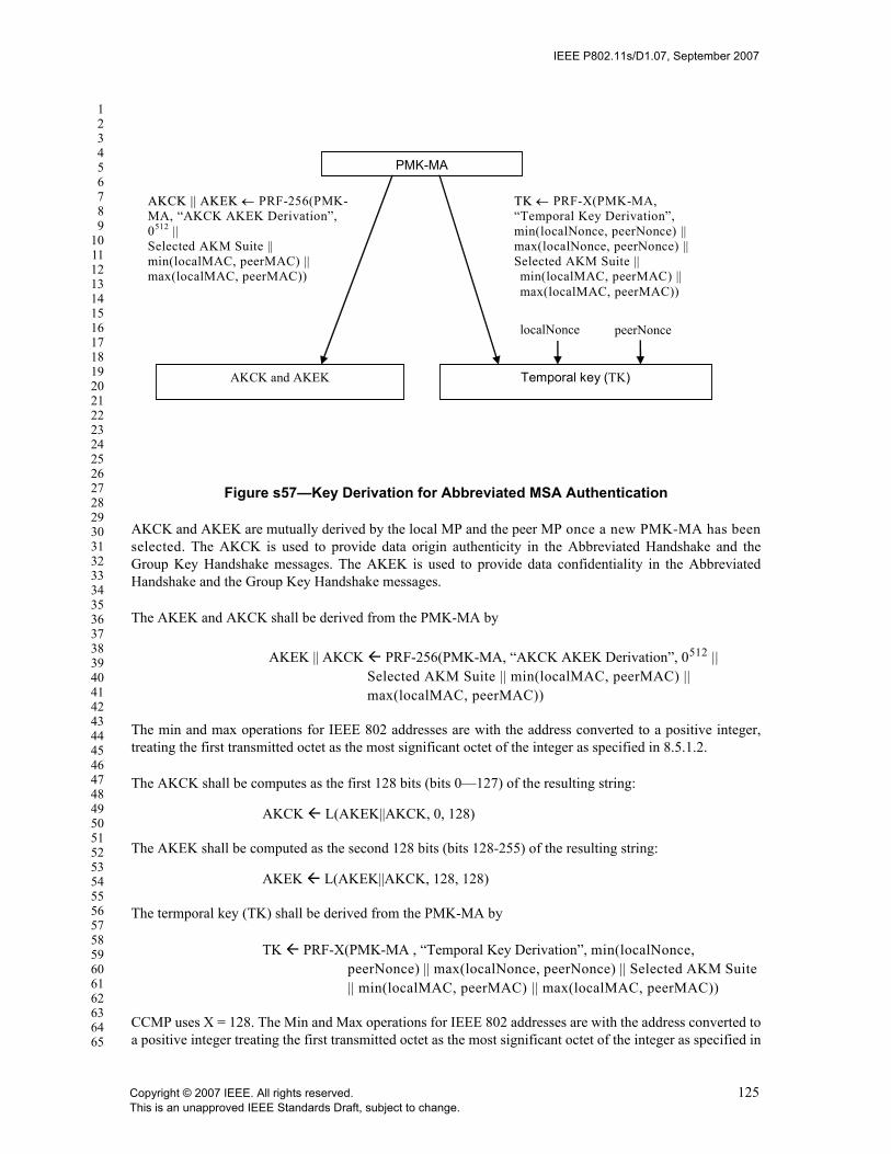
IEEE P802.11s/D1.07, September 2007
123456789
1011121314151617181920212223242526272829303132333435363738394041424344454647484950515253545556575859606162636465
Figure s57—Key Derivation for Abbreviated MSA Authentication
AKCK and AKEK are mutually derived by the local MP and the peer MP once a new PMK-MA has beenselected. The AKCK is used to provide data origin authenticity in the Abbreviated Handshake and theGroup Key Handshake messages. The AKEK is used to provide data confidentiality in the AbbreviatedHandshake and the Group Key Handshake messages.
The AKEK and AKCK shall be derived from the PMK-MA by
AKEK || AKCK PRF-256(PMK-MA, “AKCK AKEK Derivation”, 0512 || Selected AKM Suite || min(localMAC, peerMAC) || max(localMAC, peerMAC))
The min and max operations for IEEE 802 addresses are with the address converted to a positive integer,treating the first transmitted octet as the most significant octet of the integer as specified in 8.5.1.2.
The AKCK shall be computes as the first 128 bits (bits 0—127) of the resulting string:
AKCK L(AKEK||AKCK, 0, 128)
The AKEK shall be computed as the second 128 bits (bits 128-255) of the resulting string:
AKEK L(AKEK||AKCK, 128, 128)
The termporal key (TK) shall be derived from the PMK-MA by
TK PRF-X(PMK-MA , “Temporal Key Derivation”, min(localNonce, peerNonce) || max(localNonce, peerNonce) || Selected AKM Suite || min(localMAC, peerMAC) || max(localMAC, peerMAC))
CCMP uses X = 128. The Min and Max operations for IEEE 802 addresses are with the address converted toa positive integer treating the first transmitted octet as the most significant octet of the integer as specified in
PMK-MA
AKCK and AKEK Temporal key (TK)
localNonce
AAKKCCKK |||| AAKKEEKK ←← PRF-256(PMK-MA, “AKCK AKEK Derivation”, 0512 || Selected AKM Suite || min(localMAC, peerMAC) || max(localMAC, peerMAC))
TTKK ←← PRF-X(PMK-MA, “Temporal Key Derivation”, min(localNonce, peerNonce) || max(localNonce, peerNonce) || Selected AKM Suite || min(localMAC, peerMAC) || max(localMAC, peerMAC))
peerNonce
Copyright © 2007 IEEE. All rights reserved. 125This is an unapproved IEEE Standards Draft, subject to change.
IEEE P802.11s/D1.07, September 2007
123456789
1011121314151617181920212223242526272829303132333435363738394041424344454647484950515253545556575859606162636465
8.5.1.2. The Min and Max operations for nonces are with the nonces treated as positive integers converted asspecified in 7.1.1.
The TK is used to protect commnications between two peer MPs. The local MP and peer MP normallyderive a TK only once per link instance. The local MP or peer MP may use the Abbreviated MSA Hand-shake to derive a new TK.
The TK is referenced and named as follows:
TKName = PRF-128(PMK-MAName, “TK Name”, min(localNonce, peerNonce) || max(localNonce, peerNonce) || Selected AKM Suite || min(localMAC, peerMAC) || max(localMAC, peerMAC))
PMK-MAName is the identifier of the chosen PMK-MA.
11A.4.3.7 GTK Distribution
The MP shall distribute the GTK to the peer MP using the Peer Link Open frame during the AbbreviatedHandshake. The GTK subfield in MSAIE shall contain the encrypted key data. The AES key wrap, definedin IETF RFC 3394, shall be used to encrypt the GTK field using the AKEK derived from the chosen PMK-MA. The data to be encrypted shall be the bit string: {GTK || peerMAC || Key RSC || GTKExpirationTime}.The key wrap default initial value shall be used as the key wrap initialization vector..
The same encrypted key data shall be sent back to the sender when the receiver of the GTK generates a PeerLink Confirm frame. The sender, once receiving the Peer Link Confirm frame, shall verify that the sameencrypted GTK is included in the frame.
When unwrapping the GTK, the MP shall use algorithm as defined in IETF RFC 3394 with the default ini-tial value and the derived AKEK from the selected PMK-MA. The MP shall verify that the second elementin the resulting string matches the receiver's MAC address, peerMAC, as sent in the Peer Link Open frame.The MP shall extract the GTK value, the Key RSC, and GTK life time by removing the bits of the thepeerMAC from the resulting bit string of the key unwrapping operation.
If the key unwrapping operation fails or the concatenated values do not match, the GTK distribution fails,the MP shall terminate the protocol instance and shall report the reason code “MESH-INVALID-GTK”.
11A.4.3.8 MIC Computation
The MIC computation can only be done after chosen a PMK-MA is decided. For Peer Link Open and PeerLink Confirm frames, the MIC is computed using the derived KCK from the chosen PMK-MA. For PeerLink Close frames, the MIC is computed using the derived TK from the chosen PMK-MA.
The AES-128-CMAC algorithm (AES-128-CMAC is defined by FIPS SP800-38B) shall be used to computethe MIC value, over the content of the Peer Link Management frames used for Abbreviated Handshake. Thecontents protected by the MIC are specified as the following list in the specified order:
The Sender’s MAC address
The Receiver’s MAC address
All contents in the frame, except the Message Integrity Check field
126 Copyright © 2007 IEEE. All rights reserved.This is an unapproved IEEE Standards Draft, subject to change.

IEEE P802.11s/D1.07, September 2007
123456789
1011121314151617181920212223242526272829303132333435363738394041424344454647484950515253545556575859606162636465
For Peer Link Open and Peer Link Confirm frames, the key used to compute MIC is the AKEK derived fromthe chosen PMK-MA as specified in the MSA element. The MIC value for Peer Link Close frames shall becomputed using the AKCK derived from the chosen PMK-MA for the current link instance.
11A.4.3.9 Peer Link Management frames for Abbreviated Handshake
11A.4.3.9.1 General
The Peer Link Management frames shall be generated with additional information to support AbbreviatedHandshake. Detailed information is specified in 11A.4.3.9.2, 11A.4.3.9.3, and 11A.4.3.9.4 for Peer LinkClose, Peer Link Open, and Peer Link Confirm frames respectively.
Upon receiving a Peer Link Mangement frame when Abbreviated Handshake is enabled, the MP shall per-form Abbreviated Handshake specific processing operations first. Basic Peer Link Management protocolframe processing shall follow the successful Abbreviated Handshake specific operations.
11A.4.3.9.2 Constructing Peer Link Close action frames
When sending a Peer Link Close frame, the MP shall generate additional information for Abbreviated Hand-shake, specified as following:
— In the MSAIE• The Handshake Control field shall be set to 0.• The Selected AKM Suite field shall be set to an AKM suite selector that indicates the selected
AKM suite (specified in 11A.4.3.5.1).• Note—The MP will not send a Peer Link Close frame if the AKM suite selection fails.• The Selected Pairwise Cipher Suite field shall be set to the same value as in a Peer Link Open
frame, which is sent by the MP earlier for the same link instance.
Note—If the reason of sending the Peer Link Close is the pairwise cipher suite selectionfailure, the information in this field is used to inform the candidate peer MP what wasannounced by the MP for the link instance.
• The Chosen PMK field shall be set to a key identifier that indicates the selected PMK-MA (spec-ified in 11A.4.3.4).
• The Local Nonce field shall be set to the localNonce value chosen by the MP for identifying thecurrent link instance.
• The Peer Nonce field shall be set to the nonce value chosen by the peer MP for identifying thecurrent link instance.
— The MIC field shall contain a MIC. The MIC shall be calculated as specified in 11A.4.3.8 on theconcatenation in the following order:• The MP MAC address.• The Peer MP MAC address.• The contents of Peer Link Close frame body except the MIC field.
11A.4.3.9.3 Processing Peer Link Close action frames
Upon receiving a Peer Link Close frame, the MP shall first verify that the sender and receiver’s MACaddresses are different. If the MAC addresses are the same, the received frame shall be discarded.
The MP then shall perform AKM Suite selection as specified in 11A.4.3.5.1, if the AKM Suite has not beenselected. The MP shall also perform PMK selection as specified in 11A.4.3.4, if the shared PMK-MA hasnot been selected for the link instance. If either of above procedures fails, the received Peer Link Open frameshall be discarded, and corresponding event and status code shall be generated.
Copyright © 2007 IEEE. All rights reserved. 127This is an unapproved IEEE Standards Draft, subject to change.
IEEE P802.11s/D1.07, September 2007
123456789
1011121314151617181920212223242526272829303132333435363738394041424344454647484950515253545556575859606162636465
If the above procedures succeed, and the following operations shall be performed:— The MIC is checked. The received frame shall be discarded if the MIC field is not present or the MIC
verification fails.— The nonces are checked against the protocol instance. The received frame shall be discarded if the
nonces do not match. A received nonce value is a mismatch if the locally recorded peerNonce doesnot match the value in the Local Nonce field in the received frame, or the locally recoreded local-Nonce does not match the value in the Peer Nonce field in the received frame.
If all above operations succeeds, the MP shall proceed to process the Peer Link Close frame on basic param-eters as specified in 11A.2.2.1 and 11A.2.2.2.
11A.4.3.9.4 Constructing Peer Link Open action frames
When sending a Peer Link Open frame, the MP shall generate additional information for Abbreviated Hand-shake, specified as follows:
— In the RSN information element• The Group Cipher Suite field shall be set to the cipher suite selector that the MP uses for protect-
ing its broadcast/multicast traffic.• The Pairwise Cipher Suite Count field shall be set to the number of cipher suite selectors in the
Pairwise Cipher Suite list field.• The Pairwise Cipher Suite List field shall contain a series of cipher suite selectors that indicate
the pairwise cipher suites that the MP could support for protecting unicast traffic. The list isordered by the priority decided by the MP (see 11A.4.3.5).
• The AKM Suite Count field shall be set to the number of AKM suite selectors in AKM Suite Listfield.
• The AKM Suite List field shall contain a series of AKM suite selectors that indicate the AKMsuites that the MP could support for Abbreviated Handshake. The list is ordered by the prioritydecided by the MP (see 11A.4.3.5).
• The PMKID Count field shall be set to the number of PMKIDs in the PMKIDList field.• The PMKIDList field shall be set to the list of PMK-MANames that indicate the PMK-MAs that
the MP can use for the link instance, ordered by expiry time (see 11A.4.3.4).• The KDF field shall be set to the OUI of a defined KDF. The default value is 00-0F-AC: <ANA
62>.— In the MSAIE
• The Handshake Control field shall be set to 0.• The Selected AKM Suite field shall be set to the first AKM suite selector in the AKM Suite List
field in RSN information element.• The Selected Pairwise Cipher Suite field shall be set to the first cipher suite selector in the Pair-
wise Cipher Suite List field in RSN information element.• The Chosen PMK field shall be set to the first PMKID of the PMKIDList field in RSN informa-
tion element.• The Local Nonce field shall be set to the localNonce value generated by the MP for identifying
the current link instance.• The Peer Nonce field shall be set to 0.• The Optional Parameters shall contain the GTKdata subfield that contains the KDE data for the
MP’s GTK. The GTK wrapping is specified in 11A.4.3.7.— The MIC field shall contain a MIC. The MIC shall be calculated as specified in 11A.4.3.8 on the
concatenation in the following order:• The MP MAC address.• The Peer MP MAC address.• The contents of Peer Link Open frame body except the MIC field.
128 Copyright © 2007 IEEE. All rights reserved.This is an unapproved IEEE Standards Draft, subject to change.
IEEE P802.11s/D1.07, September 2007
123456789
1011121314151617181920212223242526272829303132333435363738394041424344454647484950515253545556575859606162636465
11A.4.3.9.5 Processing Peer Link Open action frames
The MP shall first verify that the sender and receiver’s MAC addresses are different. If the MAC addressesare the same, the received frame shall be discarded.
The MP then shall perform AKM suite selection as specified in 11A.4.3.5.1, if the AKM Suite has not beenselected. The MP shall also perform PMK selection as specified in 11A.4.3.4, if the shared PMK-MA hasnot been selected for the link instance. If either of above procedures fails, the received Peer Link Open frameshall be discarded, and corresponding event and status code shall be generated.
If the above procedures succeed, the following operations shall be performed:— The KDF is checked. The received frame shall be discarded if the MP does not support the KDF
announced by the candidate peer MP. The 802.11 SME shall be notified by this failure and the cur-rent protocol instance shall be terminated.
— The MIC is checked. The received frame shall be discarded if the MIC verification fails.— The nonce is checked against the protocol instance. If the nonce value mismatches, the received
frame shall be discarded. The nonce value is a mismatch if the received nonce value is not the sameas the peerNonce value maintained by the MP for the protocol instance.
— The received frame shall be rejected by sending back a Peer Link Close frame if• The security capability selection fails (see 11A.4.3.5), or• The received Pairwise Cipher Suite List does not contain the selected pairwise cipher suite, or• The received Pairwise Cippher Suite List is not the same as previously received from a Peer Link
Open frame for the same protocol instance, or• The received PMKID list does not contain the selected PMK-MA, or• The received PMKID list is not the same as previously received from a Peer Link Open frame for
the same instance, or• The received AKM Suite List does not contain the selected AKM suite, or• The received AKM Suite List is not the same as previously received from a Peer Link Open
frame for the same protocol instance.— If none of the above failures occur and the candidate peer MP’s GTK has not been unwraopped, the
MP may proceed to perform key unwrapping operation to extract the peer MP’s GTK value, as spec-ified in 11A.4.3.7. If this operation fails, the link shall be aborted by sending back a Peer Link Closewith the reason code “MESH-INVALID-GTK”.
If all above operations succeeds, the MP shall proceed to process the Peer Link Open frame on basic param-eters as specified in 11A.2.2.1 and 11A.2.2.3.
11A.4.3.9.6 Constructing Peer Link Confirm action frames
When sending a Peer Link Confirm frame, the MP shall generate additional information for AbbreviatedHandshake, specified as follows:
— In the RSN information element• The Group Cipher Suite field shall be set to the cipher suite selector that the MP uses for protect-
ing its broadcast/multicast traffic.• The Pairwise Cipher Suite Count field shall be set to the number of cipher suite selectors in the
Pairwise Cipher Suite list field. • The Pairwise Cipher Suite List field shall contain a series of cipher suite selectors that indicate
the pairwise cipher suites that the MP could support for protecting unicast traffic. The list isordered by the priority decided by the MP (see 11A.4.3.5).
• The AKM Suite Count field shall be set to the number of AKM suite selectors in AKM Suite Listfield.
Copyright © 2007 IEEE. All rights reserved. 129This is an unapproved IEEE Standards Draft, subject to change.

IEEE P802.11s/D1.07, September 2007
123456789
1011121314151617181920212223242526272829303132333435363738394041424344454647484950515253545556575859606162636465
• The AKM Suite List field shall contain a series of AKM suite selectors that indicate the AKMsuites that the MP could support for Abbreviated Handshake. The list is ordered by the prioritydecided by the MP (see 11A.4.3.5).
• The PMKID Count field shall be set to the number of PMKIDs in the PMKIDList field.• The PMKIDList field shall be set to the list of PMK-MANames that indicate the PMK-MAs that
the MP can use for the link instance, ordered by expiry time (see 11A.4.3.4).• The KDF field shall be set to 00-0F-AC: <ANA 62>
— In the MSAIE• The Handshake Control field shall be set to 0.• The Selected AKM Suite field shall be set to the AKM suite selector that indicates the success-
fully selected AKM suite (specified in 11A.4.3.5.1).• The Selected Pairwise Cipher Suite field shall be set to the cipher suite selector that indicates the
successfully selected pairwise cipher suite (specified in 11A.4.3.5.2).• The Chosen PMK field shall be set to a key identifier that indicates the successfully select-
edPMK-MA (specified in 11A.4.3.4).• The Local Nonce field shall be set to the localNonce value chosen by the MP for identifying the
current link instance.• The Peer Nonce field shall be set to the nonce value chosen by the peer MP for identifying the
current link instance.• The Optional Parameters shall contain the GTKdata subfield that contains the same value as
received in the Peer Link Open frame from the candidate peer MP.— The MIC field shall contain a MIC. The MIC shall be calculated as specified in 11A.4.3.8 on the
concatenation in the following order:• The MP MAC address.• The Peer MP MAC address.• The contents of Peer Link Confirm frame body except the MIC field.
11A.4.3.9.7 Processing Peer Link Confirm action frames
Upon receiving a Peer Link Confirm frame, the MP shall first verify that the sender and receiver’s MACaddresses are different. If the MAC addresses are the same, CNF_IGNR event shall be generated.
The MP then shall perform AKM Suite Selection as specified in 11A.4.3.5.1, if the AKM Suite has not beendecided. The MP shall also perform PMK Selection as specified in 11A.4.3.4, if the shared PMK-MA hasnot been decided for the link instance. If above procedures fail, the received Peer Link Open frame shall bediscarded, and corresponding event and status code shall be generated.
If the above procedures succeed, and the following operations shall be performed: — The KDF is checked. The received frame shall be discarded if the MP does not support the KDF
announced by the candidate peer MP. The 802.11 SME shall be notified by this failure and the cur-rent protocol instance shall be terminated.
— The MIC is checked. The received frame shall be discarded if the MIC is missing or the MIC verifi-cation fails.
— The nonces are checked against the receiving instance. The received frame shall be discarded if thenonces mismatch.The nonce value in the action frame is a mismatch if: the value in the Peer Noncefield does not match the local state of localNonce or the value in the Local Nonce field does notmatch the local state of peerNonce, excluding the case that the peerNonce value is unknown.
— The Chosen Pairwise Cipher Suite checked. If the security capability selection has been done and thereceived Chosen Pairwise Cipher Suite value is not the same as the selected value, the MP shallreject the received frame by sending a Peer Link Close frame with the reason code “Invalid pairwisecipher”.
130 Copyright © 2007 IEEE. All rights reserved.This is an unapproved IEEE Standards Draft, subject to change.

IEEE P802.11s/D1.07, September 2007
123456789
1011121314151617181920212223242526272829303132333435363738394041424344454647484950515253545556575859606162636465
— The Selected AKM Suite checked. If the AKM Suite selection has been done and the receivedSelected AKM Suite value is not the same as the selected value, the MP shall rejecte the receivedframe by sending a Peer Link Close with the reason code “Invalid AKMP”.
— If the security capability selection has not been done and the received Chosen Pairwise Cipher Suiteis not supported by the MP, the MP shall reject the received by sending a Peer Link Close framewith the reason code “Cipher suite rejected because of the security policy”.
— If the PMK selection has been done but the received Chosen PMK field is not the same as the valuereceived earlier in a Peer Link Management frame for the instance. The MP shall reject the receivedframe by sending a Peer Link Close frame with the reason code “MESH-INCONSISTENT-PARAMETERS”
— Wrapped GTK is checked. If the received value is not the same as the MP sent to the candidate peerMP during the protocol instance, the MP shall reject the received frame by sending a Peer LinkClose frame with the reason code “MESH-MISMATCH-GTK”.
— If none of the above is true and the candidate peer MP’s GTK has not been unwraopped, the MP mayproceed to perform key unwrapping operation to extract the peer MP’s GTK value, as specified in11A.4.3.7. If this operation fails, the MP shall terminate the current protocol instance by sending aPeer Link Close frame with the reason code “MESH-INVALID-GTK”.
If none of the above cases is true, the MP shall proceed to process the Peer Link Confirm action frame onbasic parameters as specified in 11A.2.2.1 and 11A.2.2.4.
11A.4.3.10 Finite State Machine
11A.4.3.10.1 Overview
The finite state machine for Abbreviated Handshake supports all the states, events, and actions defined forthe finite state machine for the Peer Link Management protocol. New events, actions, and state transitionsare added to specify the security functions for Abbreviated Handshake.
When a finite state machine is generated and actived for an Abbreviated Handshake instance, the local-Nonce shall be generated and used together with a new localLinkID to identify the instance.
11A.4.3.10.2 New Events and Actions
All events for rejecting or ignoring received action frames shall report the corresponding reason code relatedto Abbreviated Handshake functions as described in clause 11A.4.3.6.
In addition, there are four new events.
NOKEY_RJCT – This event refers to the failure of PMK selection. The trigger of this event is accompaniedwith a status code. Either the two MPs do not share a valid PMK-MA for Abbreviated Handshake (“MESH-LINK-NO-KEY”), or the chosen PMK-MA by the MP is not a shared PMK-MA by the two MPs. Thereceived Peer Link Management frame shall be discarded. Thus the link instance shall be closed. However,the MP shall not send a Peer Link Close frame as the result of this event.
NOAKM_RJCT—This event refers to the failure of AKM Suite Selection. The trigger of this event isaccompanied with a status code. Either the two MPs do not share a valid AKM suite for Abbreviated Hand-shake (“MESH-LINK-NO-AKM”), or the chosen AKM suite by the MP is not a shared AKM by the twoMPs (“MESH-LINK-ALT-AKM”). The received Peer Link Management frame shall be discarded. Thus thelink instance shall be closed. However, the MP shall not send a Peer Link Close frame as the result of thisevent.
Copyright © 2007 IEEE. All rights reserved. 131This is an unapproved IEEE Standards Draft, subject to change.

IEEE P802.11s/D1.07, September 2007
123456789
1011121314151617181920212223242526272829303132333435363738394041424344454647484950515253545556575859606162636465
NOKDF_RJCT—This event refers to the failure of supporting the KDF that the candidate peer MP supports.The trigger of this event is accompanied with a status code, “MESH-LINK-NO-KDF”. The received PeerLink Management frame shall be discarded. Thus the link instance shall be closed. However, the MP shallnot send a Peer Link Close frame as the result of this event.
TOR3 – This event refers to Timeout(localLinkID, retryTimer), the dot11MESHMAXRetries has beenreached, with the Abbreviated Handshake enabled. The link instance shall be closed when TOR3 occurs.Since the PMK selection never occurs, the MP shall not send Peer Link Close frame.
The actions of sending peer link management frames are updated as the following.
sndOPN – Generate a Peer Link Open frame for the current Abbreviated Handshake protocol instance (asspecified in 11A.4.3.9.4) and send it to the candidate peer MP.
sndCNF – Generate a Peer Link Confirm frame for the current Abbreviated Handshake protocol instance (asspecified in 11A.4.3.9.6) and send it to the candidate peer MP.
sndClose – Generate a Peer Link Close frame for the current Abbreviated Handshake protocol instance (asspecified in 11A.4.3.9.2) and send it to the candidate peer MP.
11A.4.3.10.3 State transitions
All state transitions specified in Peer Link Management finite state machine shall be used for AbbreviatedHandshake finite state machine.
In LISTEN state, the following are the additional state transitions and performed actions
The NOKEY_RJCT event shall be ignored
When NOAKM_RJCT event occurs, the finite state machine transitions to IDLE state
When OPN_IGNR event occurs with the status code MESH-LINK-ALT-PMK, the status code and thecandidate peer MP’s choice of the PMK-MA for the instance shall be reported to IEEE 802 SME viaMLME-SignalLinkStatus.indication primitive.
When NOKDF_RJCT event occurs, the status code MESH-LINK-NO-KDF and candidate peer MP’sannouncement of the KDF for the link instance shall be reported to IEEE 802 SME via MLME-SignalLinkStatus.indication primitive.
In OPN_SNT state, the following are additional state transitions and actions
When NOKEY_RJCT event occurs, the MLME-SignalLinkStatus.indication primitive shall be used toinform the IEEE 802 SME the failure of establishing the authenticated peer link with the status codeMESH-LINK-NO-PMK. The received Peer Link Open frame shall be discarded. The retryTimer iscleared and the finite state machine transitions to IDLE state.
When NOAKM_RJCT event occurs, the MLME-SignalLinkStatus.indication primitive shall be used toinform to IEEE 802 SME the failure of establishing the authenticated peer lin with the status codeMESH-LINK-NO-PMK. The received Peer Link Open frame shall be discarded. The retryTimer iscleared and the finiate state machine transitions to HOLDING state.
When OPN_IGNR event occurs with the status code MESH-LINK-ALT-PMK, the status code and thecandidate peer MP’s choice of the PMK-MA for the instance shall be reported to IEEE 802 SME viaMLME-SignalLinkStatus.indication primitive.
132 Copyright © 2007 IEEE. All rights reserved.This is an unapproved IEEE Standards Draft, subject to change.
IEEE P802.11s/D1.07, September 2007
123456789
1011121314151617181920212223242526272829303132333435363738394041424344454647484950515253545556575859606162636465
When NOKDF_RJCT event occurs, the MLME-SignalLinkStatus.indication primitive shall be used toinform the IEEE 802 SME the failure of establishing the authenticated peer link with the status codeMESH-LINK-NO-KDF. The received Peer Link Open frame shall be discarded. The retryTimer iscleared and the finite state machine transitions to HOLDING state.
When TOR3 event occurs, the MLME-SignalLinkStatus.indication primitive shall be used to inform theIEEE 802 SME the failure of establishing the peer link with the status code “MESH-LINK-MAX-RETIES”. The finite state machine transitions to HOLDING state.
In OPN_RCVD state, the following are the additional actions
When CNF_ACPT event occurs, in addition to the actions for Peer Link Management protocol, theMLME-installKey.request primitive shall be called to install the established temporal key and receivedGTK from the peer MP.
In CNF_RCVD state, the following are the additional actions
When CNF_ACPT event occurs, in addition to the actions for Peer Link Management protocol, theMLME-installKey.request primitive shall be called to install the established temporal key and receivedGTK from the peer MP.
Table s43 and Figure s57 specify the state transitions of the finite state machine for Abbreviated Handshake.The text in red highlights the additional new state transitions for Abbreviated Handshake, compared withPeer Link Mangaement finite state machine for basic peer links.
Copyright © 2007 IEEE. All rights reserved. 133This is an unapproved IEEE Standards Draft, subject to change.

IEEE P802.11s/D1.07, September 2007
123456789
1011121314151617181920212223242526272829303132333435363738394041424344454647484950515253545556575859606162636465
Table s47—Abbreviated Handshake Finite State Machine
To State
IDLE LISTEN OPN_SNT CNF_RCVD OPN_RCVD
ESTAB HOLDING
From
Sta
te
IDLE PASOPN/ --
ACTOPN/ (sndOPN, setR)
LISTEN CNCL, NOKEY_RJCT,NOAKM_RJCT, NOKDF_RJCT / --
ACTOPN/ (sndOPN, setR)
OPN_ACPT/ (sndOPN, sndCNF, setR)
OPN_SNT TOR1/ (sndOPN, setR)
CNF_ACPT/ (clR, setC)
OPN_ACPT/ (sndCNF)
CLS_ACPT, OPN_RJCT, CNF_RJCT, TOR2, CNCL/ (snd-CLS, clR, setH)TOR3, NOKEY_RJCT, NOAKM_RJCT, NOKDF_RJCT / (clR, setH)
CNF_RCVD CNF_ACPT / --
OPN_ACPT / (clC, snd-CNF)
CLS_ACPT, OPN_RJCT, CNF_RJCT, CNCL/ (snd-CLS, clC, setH)TOC / (snd-CLS, setH)
OPN_RCVD
TOR1 / (sndOPN, setR)
CNF_ACPT / clR
CLS_ACPT, OPN_RJCT, CNF_RJCT,TOR2, CNCL/ (snd-CLS, clR, setH)
ESTAB OPN_ACPT / sndCNF
CLS_ACPT, OPN_RJCT, CNF_RJCT,CNCL/ (snd-CLS, setH)
HOLDING TOH, CLS_ACPT / --
OPN_ACPT, CNF_ACPT, OPN_RJCT, CNF_RJCT / sndCLS
134 Copyright © 2007 IEEE. All rights reserved.This is an unapproved IEEE Standards Draft, subject to change.

IEEE P802.11s/D1.07, September 2007
123456789
1011121314151617181920212223242526272829303132333435363738394041424344454647484950515253545556575859606162636465
l
Figure s58—Finite State Machine of Abbreviated Handshake Protocol
Copyright © 2007 IEEE. All rights reserved. 135This is an unapproved IEEE Standards Draft, subject to change.

IEEE P802.11s/D1.07, September 2007
123456789
1011121314151617181920212223242526272829303132333435363738394041424344454647484950515253545556575859606162636465
11A.4.4 Mesh Group Key Handshake
The Mesh Group Key Handshake may be used by either MP, after a secure peer link has been established, toupdate the GTK that it uses to protect broadcast and multicast MPDUs that it transmits. The Mesh GroupKey Handshake is similar to the Group Key Handshake defined in 8.5.4, but with minor updates required foruse within a mesh.
The EAPOL-Key frame notation is defined in 8.5.2.1. The "GTK Source" is the MP that is sending the GTKto a peer MP using this protocol. A "GTK Recipient" is an MP receiving the GTK being sent by the GTKSource.
Message 1: GTK Source ? GTK Recipient: EAPOL-Key(1,1,1,0,G,0,KeyRSC,0,MIC,DataKD_GM1) where DataKD_GM1 = (Mesh GTK Delivery KDE, GTK KDE).
Message 2: GTK Recipient ? GTK Source: EAPOL-Key(1,1,0,0,G,0,0,0,MIC,DataKD_GM2)where DataKD_GM2 = Mesh GTK Delivery KDE.
The contents of each message shall be as described in 8.5.4, except as follows:
— Message 1: The Key Data field shall contain a Mesh GTK Delivery KDE (see 8.5.2), where theSender MP Address field is set to the MAC address of the GTK Source, and the Destination MPAddress field is set to the MAC address of the GTK Recipient. The Key Data field shall also containthe GTK KDE containing the GTK to be sent. The entire Key Data field shall be encrypted. TheKey Data Length field shall indicate the length of the Key Data field after encryption, including anypadding.
— Message 2: The Key Data field shall contain a Mesh GTK Delivery KDE (see 8.5.2), where theSender MP Address field is set to the MAC address of the GTK Recipient, and the Destination MPaddress field is set to the MAC address of the GTK Source. The Key Data field shall not beencrypted. The Key Data Length field shall indicate the length of the Mesh GTK Delivery KDE.
The processing, upon reception, of Message 1 of the Mesh Group Key Handshake shall be as described in8.5.4.1. Additionally, after verifying the MIC, the recipient of Message 1 shall verify that the Sender andDestination MP address fields in the Mesh GTK Delivery KDE contain the MAC address of the MP sendingthe GTK and the local MP's MAC address, respectively. If these addresses are not correctly included, themessage shall be silently discarded.
The processing, upon reception, of Message 2 of the Mesh Group Key Handshake shall be as described in8.5.4.2. Additionally, after verifying the MIC, the recipient of Message 2 shall verify that the Sender andDestination MP address fields in the Mesh GTK Delivery KDE contain the MAC address of the GTK Recip-ient and the local MP's MAC address, respectively. If these addresses are not correctly included, the mes-sage shall be silently discarded.
11A.4.5 Mesh key holder security association
A security association is established between an MA and MKD to provide secure communications betweenkey holders within a mesh. The mesh key holder security association is used to enable message integrity anddata origin authenticity in all messages passed between MA and MKD after the security association is estab-lished. Further, it provides confidentiality of derived keys and key context during key delivery protocols. Es-tablishing the mesh key holder security association begins with discovery of the MKD, followed by ahandshake initiated by the MA. The result of the security association is the pairwise transient key for keyderivation (MPTK-KD), used to provide the security services between MA and MKD.
136 Copyright © 2007 IEEE. All rights reserved.This is an unapproved IEEE Standards Draft, subject to change.

IEEE P802.11s/D1.07, September 2007
123456789
1011121314151617181920212223242526272829303132333435363738394041424344454647484950515253545556575859606162636465
Note: to become a mesh authenticator, the MP must execute the Mesh Key Holder Security Handshake, unless it is co-located with an MKD.
11A.4.5.1 Mesh key distributor discovery
If an MA is not also an MKD, the MA may obtain the MKD-ID address of its MKD from the MSAIE con-veyed during its Initial MSA Authentication. Subsequently, the MA may initiate the MEsh Key Holder Se-curity Handshake described in 11A.4.5.2.
If the MA is co-located with an MKD (in the same physical device), there is no need for the MA to performthe Mesh Key Holder Security Handshake.
11A.4.5.2 Mesh Key Holder Security Handshake
The Mesh Key Holder Security Handshake may be initiated by an MP after it has completed its Initial MSAAuthentication. This handshake permits an “aspirant MA” to establish a security association with the MKDthat derived its PMK-MKD during Initial MSA Authentication. An “aspirant MA” is defined as an MP thathas completed Initial MSA Authentication with an MKD, and that will become an MA after completing theMesh Key Holder Security Handshake with the same MKD.
The Mesh Key Holder Security Handshake consists of 4 messages, as shown in Figure s59. While the fourthmessage is not required for authentication and establishment of the MPTK-KD, its presence permits theaspirant MA alone to manage retries of handshake messages. That is, the aspirant MA is responsible forretransmitting handshake messages 1 and 3 if it does not receive responses to those messages, while theMKD only responds to messages that it receives. The aspirant MA initiates the exchange by constructingMesh Key Holder Security Handshake message 1 (see 11A.4.5.2.1), and sending the message to the MKDidentified by the MKD-ID received during the aspirant MA’s Initial MSA Authentication.
Figure s59—Mesh Key Holder Security Handshake
mesh key distributormesh authenticator
Mesh Key Holder Security Handshake message 1
Mesh Key Holder Security Handshake message 2
Mesh Key Holder Security Handshake message 3
Mesh Key Holder Security Handshake message 4
Copyright © 2007 IEEE. All rights reserved. 137This is an unapproved IEEE Standards Draft, subject to change.

IEEE P802.11s/D1.07, September 2007
123456789
1011121314151617181920212223242526272829303132333435363738394041424344454647484950515253545556575859606162636465
During the handshake, the aspirant MA selects a Key Holder Transport type from among those advertised bythe MKD during the handshake. Supported transport types are also provided in the MSAIE received duringthe aspirant MA’s Initial MSA Authentication. The aspirant MA shall not establish a mesh key holder secu-rity association with the MKD if the Key Holder Transport protocols supported by the aspirant MA andMKD do not overlap, or if the Key Holder Transport List received by the aspirant MA contains the singleentry 00-0F-AC:0.
After completing the handshake, the aspirant MA sets both the “Mesh Authenticator” and “Connected toMKD” bits to 1 in the MSCIE in its Beacon frames and Probe Response frames to advertise that it is config-ured as a mesh authenticator that is connected to the MKD. The MSCIE shall contain the MKDD-ID that isreceived from the MKD in mesh key holder security handshake message 2.
An MA shall maintain a mesh path to the MKD. If the mesh path is lost and cannot be repaired, the MAshall set the “Connected to MKD” bit to 0 in the MSCIE. The MA may maintain cached keys (but a PMK-MA must be deleted when its lifetime expires). In such a case, the “Mesh Authenticator” bit may remain setto 1 to indicate the presence of cached keys. After the mesh path is re-established, the MA may again set the“Connected to MKD” bit to 1.
The MA and the MKD maintain separate key replay counters for sending messages that are protected usingthe MPTK-KD, as described in 11A.4.5.3. Immediately upon deriving the MPTK-KD, both the MKD andMA shall reset their replay counters to zero. The lifetime of the MPTK-KD is the same as that of the MKDK.
11A.4.5.2.1 Mesh Key Holder Security Handshake message 1
Mesh Key Holder Security Handshake message 1 is a Mesh Key Holder Handshake frame (see 7.4b.1.1) withthe following contents:
The MAC address of the MKD shall be asserted in the DA field of the message header.
The MAC address of the aspirant MA shall be asserted in the SA field of the message header.
The Mesh ID information element shall contain the Mesh ID that the aspirant MA advertises in its Beaconframes and Probe Response frames.
The MSCIE shall contain the value of MKDD-ID that was contained in the MSCIE received in peer link es-tablishment messages during the aspirant MA’s Initial MSA Authentication. The Mesh Security Configura-tion field shall be set to zero.
The Key Holder Security field shall be set as follows:— Handshake Sequence shall be set to 1.— MA-Nonce shall be set to a value chosen randomly (see 8.5.7) by the aspirant MA, following the rec-
ommendations of 8.5.7.— MKD-Nonce shall be set to zero.— MA-ID shall be set to the MAC address of the aspirant MA.— MKD-ID shall be set to the MAC address of the MKD.
The Key Holder Transport Count subfield of the Key Holder Transport field shall be set to zero, and the KeyHolder Transport List subfield shall be omitted.
The Status Code field shall be set to zero.
The message integrity check field shall be omitted.
138 Copyright © 2007 IEEE. All rights reserved.This is an unapproved IEEE Standards Draft, subject to change.

IEEE P802.11s/D1.07, September 2007
123456789
1011121314151617181920212223242526272829303132333435363738394041424344454647484950515253545556575859606162636465
Upon receiving handshake message 1, the MKD verifies that the values of Mesh ID, MKDD-ID, and MKD-ID match the local values of dot11MeshID, dot11MeshKeyDistributorDomainID, and the local MACaddress; if not, handshake message 1 is silently discarded. Then, the MKD shall determine if the aspirantMA (as identified by MA-ID in the received message) is authorized to become an MA; see 8.8.9.2. If not,message 1 is discarded.
If authorized, the MKD chooses MKD-Nonce, a value chosen randomly (following the recommendations of8.5.7), and computes the MPTK-KD using the MA-Nonce received in handshake message 1 and MKD-Nonce (see 8.8.8). If MPTK-KD derivation fails, the MKD silently discards message 1. Otherwise, theMKD sends handshake message 2, with contents as given in 11A.4.5.2.2.
If the MKD receives a duplicate handshake message 1 after sending handshake message 2, it shall retransmithandshake message 2.
11A.4.5.2.2 Mesh Key Holder Security Handshake message 2
Mesh Key Holder Security Handshake message 2 is a Mesh Key Holder Handshake frame with the followingcontents:
The MAC address of the aspirant MA shall be asserted in the DA field of the message header.
The MAC address of the MKD shall be asserted in the SA field of the message header.
The Mesh ID information element shall contain the Mesh ID as configured in dot11MeshID.
The MSCIE shall contain the MKDD-ID as configured in dot11MeshKeyDistributorDomainID. The MeshSecurity Configuration field shall be set to zero.
The Key Holder Security field shall be set as follows:— Handshake Sequence shall be set to 2.— MA-Nonce, MA-ID, and MKD-ID shall be set to the values contained in handshake message 1.— MKD-Nonce shall be set to a value chosen randomly by the MKD, prior to computation of the
MPTK-KD.
The Key Holder Transport Count subfield of the Key Holder Transport field shall contain the number oftransport type selectors present in the Key Holder Transport List subfield. The Key Holder Transport Listsubfield shall contain the list of transport types supported by the MKD.
The Status Code field shall be set to zero.
The MPTK-KDShortName subfield of the message integrity check field shall contain the identifier of theMPTK-KD derived after receiving message 1. The MIC subfield shall contain a 16-octet MIC calculatedusing the MKCK-KD portion of the identified MPTK-KD, using the AES-128-CMAC algorithm (AES-128-CMAC is defined by FIPS SP800-38B), on the concatenation in the following order, of:
— Contents of the Category field of the Mesh Key Holder Handshake MSA multihop action frame.— Contents of the Action Value field of the Mesh Key Holder Handshake MSA multihop action frame.— Contents of the Mesh ID information element, from the element ID to the end of the Mesh ID infor-
mation element.— Contents of the MSCIE, from the element ID to the end of the MSCIE.— Contents of the Key Holder Security field.— Contents of the Key Holder Transport field
Copyright © 2007 IEEE. All rights reserved. 139This is an unapproved IEEE Standards Draft, subject to change.

IEEE P802.11s/D1.07, September 2007
123456789
1011121314151617181920212223242526272829303132333435363738394041424344454647484950515253545556575859606162636465
— Contents of the Status Code field
Upon receiving handshake message 2, the aspirant MA shall compute the MPTK-KD as defined in 8.8.8.The aspirant MA shall compute the MPTK-KDShortName and shall verify that it matches that received inhandshake message 2, and subsequently shall verify the MIC. If either verification fails, the aspirant MAshall silently discard handshake message 2.
The aspirant MA shall verify that Mesh ID, MKDD-ID, MA-Nonce, MA-ID, and MKD-ID match the valuesfrom handshake message 1; if not, handshake message 3 shall indicate an error status code "The Mesh KeyHolder Security Handshake message was malformed." The aspirant MA shall verify that it supports one ormore of the Key Holder Transport types listed in the Key Holder Transport field; if not, handshake message3 shall indicate an error status code "No listed Key Holder Transport type is supported."
Subsequently, the aspirant MA sends handshake message 3, with contents as given in 11A.4.5.2.3. Hand-shake message 3 shall be sent within time dot11MeshKHHandshakeTimeout of receiving handshake mes-sage 2. If the aspirant MA sent handshake message 3 with a nonzero status code, it shall securely delete theMPTK-KD and shall ensure "Connected to MKD" is set to 0 in the MSCIE that it advertises in BeaconFrames and Probe Response Frames.
If the aspirant MA does not receive handshake message 2 in response to handshake message 1, it shallretransmit handshake message 1, if it has not yet attempted dot11MeshKHHandshakeAttempts transmits ofhandshake message 1. The timeout value between retransmissions shall bedot11MeshKHHandshakeTimeout. If handshake message 2 has not been received afterdot11MeshKHHandshakeAttempts transmissions and a final timeout, the aspirant MA shall ensure "Con-nected to MKD" is set to 0 in the MSCIE that it advertises in Beacon Frames and Probe Response Frames,and abort the handshake.
11A.4.5.2.3 Mesh Key Holder Security Handshake message 3
Mesh Key Holder Security Handshake message 3 is a Mesh Key Holder Handshake frame with the followingcontents:
The MAC address of the MKD shall be asserted in the DA field of the message header.
The MAC address of the aspirant MA shall be asserted in the SA field of the message header.
The Mesh ID information element shall contain the Mesh ID information element received in handshake mes-sage 2.
The MSCIE shall contain the MSCIE received in handshake message 2.
The Key Holder Security field shall be set as follows:
— Handshake Sequence shall be set to 3.
— MA-Nonce, MKD-Nonce, MA-ID, and MKD-ID shall be set to the values contained in handshakemessage 2.
The Key Holder Transport Count subfield of the Key Holder Transport field shall contain the number oftransport type selectors present in the Key Holder Transport List subfield (0 or 1). If the Status Code field isnonzero, the Key Holder Transport List subfield shall be omitted. Otherwise, the Key Holder Transport Listsubfield shall contain a single transport type selector from among those received in handshake message 2and that is selected by the aspirant MA.
140 Copyright © 2007 IEEE. All rights reserved.This is an unapproved IEEE Standards Draft, subject to change.

IEEE P802.11s/D1.07, September 2007
123456789
1011121314151617181920212223242526272829303132333435363738394041424344454647484950515253545556575859606162636465
The Status Code field shall indicate the error resulting from the processing of handshake message 2. If noerror resulted, then Status Code shall be set to zero.
The MPTK-KDShortName subfield of the message integrity check field shall contain the identifier of theMPTK-KD derived after receiving message 2. The MIC subfield shall contain a MIC. The 16-octet MICshall be calculated using the MKCK-KD portion of the identified MPTK-KD, using the AES-128-CMACalgorithm (AES-128-CMAC is defined by FIPS SP800-38B), on the concatenation in the following order,of:
— Contents of the Category field of the Mesh Key Holder Handshake MSA multihop action frame.— Contents of the Action Value field of the Mesh Key Holder Handshake MSA multihop action frame.— Contents of the Mesh ID information element, from the element ID to the end of the Mesh ID infor-
mation element.— Contents of the MSCIE, from the element ID to the end of the MSCIE.— Contents of the Key Holder Security field.— Contents of the Key Holder Transport field— Contents of the Status Code field
Upon receiving handshake message 3, the MKD shall verify that MPTK-KDShortName identifies theMPTK-KD derived during this handshake, and subsequently shall verify the MIC. If either verificationfails, the MKD shall silently discard handshake message 3.
If the status code is nonzero, the MKD shall securely delete the MPTK-KD, and handshake message 4 shallnot be sent.
Otherwise, the MKD shall verify that Mesh ID, MKDD-ID, MA-Nonce, MA-ID, and MKD-ID match thevalues from handshake message 2; if not, handshake message 4 shall indicate an error status code "TheMesh Key Holder Security Handshake message was malformed." The MKD shall verify that it supports theselected Key Holder Transport type listed in the Key Holder Transport field; if not, handshake message 4shall indicate an error status code "No listed Key Holder Transport type is supported."
Subsequently, the MKD sends handshake message 4, with contents as given in 11A.4.5.2.4. The MKDshall reset all key replay counters (see 11A.4.5.3) for messages protected using the MPTK-KD. If the MKDsent handshake message 4 with a nonzero status code, it shall securely delete the MPTK-KD, as the hand-shake has failed.
If the MKD receives a duplicate handshake message 3 after sending handshake message 4, it shall retransmithandshake message 4.
11A.4.5.2.4 Mesh Key Holder Security Handshake message 4
Mesh Key Holder Security Handshake message 4 is a Mesh Key Holder Handshake frame with the follow-ing contents:
The MAC address of the aspirant MA shall be asserted in the DA field of the message header.
The MAC address of the MKD shall be asserted in the SA field of the message header.
The Mesh ID information element shall contain the Mesh ID information element received in handshakemessage 3.
The MSCIE shall contain the MSCIE received in handshake message 3.
Copyright © 2007 IEEE. All rights reserved. 141This is an unapproved IEEE Standards Draft, subject to change.

IEEE P802.11s/D1.07, September 2007
123456789
1011121314151617181920212223242526272829303132333435363738394041424344454647484950515253545556575859606162636465
The Key Holder Security field shall be set as follows:
— Handshake Sequence shall be set to 4.
— MA-Nonce, MKD-Nonce, MA-ID, and MKD-ID shall be set to the values contained in handshakemessage 3.
The Key Holder Transport Count subfield of the Key Holder Transport field shall contain the number oftransport type selectors present in the Key Holder Transport List subfield (0 or 1). If the Status Code field isnonzero, the Key Holder Transport List subfield shall be omitted. Otherwise, the Key Holder Transport Listsubfield shall contain the single transport type selector received in handshake message 3.
The Status Code field shall indicate the error resulting from the processing of handshake message 3. If noerror resulted, then Status Code shall be set to zero.
The MPTK-KDShortName subfield of the message integrity check field shall contain the identifier of theMPTK-KD derived after receiving message 1. The MIC subfield shall contain a MIC. The 16-octet MICshall be calculated using the MKCK-KD portion of the identified MPTK-KD, using the AES-128-CMACalgorithm (AES-128-CMAC is defined by FIPS SP800-38B), on the concatenation in the following order,of:
— Contents of the Category field of the Mesh Key Holder Handshake MSA mesh action frame.
— Contents of the Action Value field of the Mesh Key Holder Handshake MSA mesh action frame.
— Contents of the Mesh ID information element, from the element ID to the end of the Mesh ID infor-mation element.
— Contents of the MSCIE, from the element ID to the end of the MSCIE.
— Contents of the Key Holder Security field.
— Contents of the Key Holder Transport field.
— Contents of the Status Code field.
Upon receiving handshake message 4, the aspirant MA shall verify that MPTK-KDShortName identifies theMPTK-KD derived during this handshake, and subsequently shall verify the MIC. If either verificationfails, the MKD shall silently discard handshake message 4.
If the status code is nonzero, the handshake fails. Otherwise, the aspirant MA shall verify that Mesh ID,MKDD-ID, MA-Nonce, MA-ID, MKD-ID, and the Key Holder Transport field match the values from hand-shake message 3; if not, the handshake fails.
If the aspirant MA does not receive handshake message 4 in response to handshake message 3, it shallretransmit handshake message 3, if it has not yet attempted dot11MeshKHHandshakeAttempts transmits ofhandshake message 3. The timeout value between retransmissions shall bedot11MeshKHHandshakeTimeout. If handshake message 4 has not been received afterdot11MeshKHHandshakeAttempts transmissions and a final timeout, the handshake fails.
If the handshake failed, the aspirant MA shall securely delete the MPTK-KD and shall ensure "Connected toMKD" is set to 0 in the MSCIE that it advertises in Beacon Frames and Probe Response Frames. Otherwise,the handshake completed successfully, and the aspirant MA shall set both the "Mesh Authenticator" and"Connected to MKD" bits to 1 in the MSCIE. Further the aspirant MA shall reset the key replay countersdefined in 11A.4.5.3 for use with the MPTK-KD.
142 Copyright © 2007 IEEE. All rights reserved.This is an unapproved IEEE Standards Draft, subject to change.

IEEE P802.11s/D1.07, September 2007
123456789
1011121314151617181920212223242526272829303132333435363738394041424344454647484950515253545556575859606162636465
11A.4.5.3 Key Replay Counters
The MA and MKD each maintain key replay counters for use in the Mesh Key Transport and Mesh EAPMessage Transport protocols indicated by Key Holder Transport type selector 00-0F-AC:1. The followingkey replay counters are defined:
— MA-KEY-TRANSPORT is used to protect the Mesh Key Pull Protocol (11A.4.6.1).— MA-EAP-TRANSPORT is used to protect the Mesh EAP Message Transport Protocol (11A.4.7).— MKD-KEY-TRANSPORT is used to protect the Mesh Key Push Protocol (11A.4.6.2) and Mesh
Key Delete Protocol (11A.4.6.3).
All key replay counters for use between an MA and MKD shall be set to zero upon successful completion ofthe Mesh Key Holder Security Handshake by the same MA and MKD.
In each protocol that is protected by a key replay counter, the sender shall increment the value of the appro-priate replay counter prior to sending the first message. Upon receiving the first message, the recipient shallverify that the replay counter value contained in the first message is a value not yet used by the sender in afirst message. If the replay counter value has been previously used, the message shall be discarded.
Further, subsequent messages of a protocol shall contain the same replay counter value as in the first mes-sage of the protocol, to permit matching messages within a protocol instance.
11A.4.6 Mesh Key Transport Protocols
The Mesh Key Transport Protocols describe how the MKD manages the transport of keys to MAs. The useof these protocols is selected during the Mesh Key Holder Security Handshake defined in 11A.4.5.2 and isdescribed by transport type selector 00-0F-AC:1. When the transport type selector specifies any other value,the mechanism for Key Transport is beyond the scope of this standard.
The Mesh Key Transport Protocols permit the MKD to securely transmit a derived PMK-MA to an MA, alongwith related information (e.g. the key lifetime). The MKD may also request that the MA delete a key that haspreviously been delivered.
Three protocols are defined for mesh key delivery and management. The Mesh Key Pull Protocol is initiatedby the MA to request delivery of a PMK-MA, and consists of two messages, as depicted in Figure s60. TheMesh Key Push Protocol is initiated by the MKD sending a notification identifying a PMK-MA, after whichthe MA initiates the Mesh Key Pull protocol to retrieve the referenced key; this is shown in Figure s61. Fi-nally, the Mesh Key Delete Protocol is initiated by the MKD to request that the MA delete the identified
Copyright © 2007 IEEE. All rights reserved. 143This is an unapproved IEEE Standards Draft, subject to change.
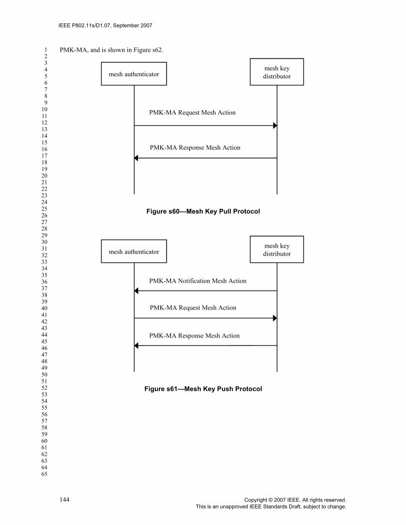
IEEE P802.11s/D1.07, September 2007
123456789
1011121314151617181920212223242526272829303132333435363738394041424344454647484950515253545556575859606162636465
PMK-MA, and is shown in Figure s62.
Figure s60—Mesh Key Pull Protocol
Figure s61—Mesh Key Push Protocol
mesh key distributormesh authenticator
PMK-MA Request Mesh Action
PMK-MA Response Mesh Action
mesh key distributormesh authenticator
PMK-MA Notification Mesh Action
PMK-MA Request Mesh Action
PMK-MA Response Mesh Action
144 Copyright © 2007 IEEE. All rights reserved.This is an unapproved IEEE Standards Draft, subject to change.

IEEE P802.11s/D1.07, September 2007
123456789
1011121314151617181920212223242526272829303132333435363738394041424344454647484950515253545556575859606162636465
Figure s62—Mesh Key Delete Protocol
11A.4.6.1 Mesh Key Transport Pull protocol
The Mesh Key Transport Pull Protocol is a two-message exchange consisting of a PMK-MA Request framesent to the MKD, followed by a PMK-MA Response frame providing key delivery sent to the MA. Both mes-sages contain a MIC for integrity protection, and the PMK-MA being delivered is encrypted.
Mesh Key Transport Pull message 1 is a PMK-MA Request frame (see 7.4b.1.3). The MAC address of theMKD shall be asserted in the DA field of the message header, and the MAC address of the MA shall be as-serted in the SA field of the message header. Prior to constructing the message, the MA shall increment theMA-KEY-TRANSPORT replay counter associated with the MPTK-KD by 1.
The contents of the Mesh Key Transport Control field shall be as follows:— Replay counter shall be set to the value of the MA-KEY-TRANSPORT replay counter.— SPA shall be set to the MAC address of the MP that, during its Initial MSA Authentication, gener-
ated the mesh key hierarchy that includes the PMK-MA being requested— PMK-MKDName shall be set to the identifier of the key from which the PMK-MA being requested
was derived.— MPTKANonce shall be set to zero.
The MPTK-KDShortName subfield of the message integrity check field shall contain the identifier of theMPTK-KD currently valid for secure communications with the MA. The MIC subfield shall contain a MIC.The 16-octet MIC shall be calculated using the MKCK-KD portion of the identified MPTK-KD, using theAES-128-CMAC algorithm (AES-128-CMAC is defined by FIPS SP800-38B) on the concatenation in thefollowing order, of:
— MA MAC address— MKD MAC address— Contents of the Category field of the PMK-MA Request MSA multihop action frame.
mesh key distributormesh authenticator
PMK-MA Delete Mesh Action
PMK-MA Response Mesh Action
Copyright © 2007 IEEE. All rights reserved. 145This is an unapproved IEEE Standards Draft, subject to change.

IEEE P802.11s/D1.07, September 2007
123456789
1011121314151617181920212223242526272829303132333435363738394041424344454647484950515253545556575859606162636465
— Action Value field of the PMK-MA Request MSA multihop action frame, which contains the valueshown for “PMK-MA Request” in Table s35.
— Contents of the Mesh Key Transport Control field.
Upon receiving message 1, the MKD shall verify that the MPTK-KDShortName identifies the MPTK-KDcurrently valid for secure communications with the MA, shall verify the MIC, and shall verify that the Replaycounter field contains a value larger than the current value of the MA-KEY-TRANSPORT replay counter. Ifany verification fails, the MKD shall silently discard the received message. If verified, the MKD shall set thelocal MA-KEY-TRANSPORT replay counter to the value received in message 1. The MKD shall attempt toderive the PMK-MA for use between the MP identified by SPA and the MA that sent message 1, using thekey identified by PMK-MKDName. Subsequently, the MKD constructs and sends message 2.
Mesh Key Pull Protocol message 2 is a PMK-MA Response frame (see 7.4b.1.4). The MAC address of theMA shall be asserted in the DA field of the message header, and the MAC address of the MKD shall be as-serted in the SA field of the message header.
The Key Transport Response field shall be set to zero if a PMK-MA is being delivered in this message. Ifthe MKD was unable to derive the requested PMK-MA using the information in message 1, the Key Trans-port Response field shall be set to 1.
The contents of the Mesh Key Transport Control field shall be as follows:— Replay counter shall be set to the current value of the MA-KEY-TRANSPORT replay counter (i.e.,
the value of replay counter in message 1).— SPA and PMK-MKDName shall be set to the values contained in message 1.— MPTKANonce shall be set to the pseudo-random value that was selected by the MKD for derivation
of the PMK-MKDName that was indicated in message 1. However, if the Key Transport Responsefield is nonzero, then the MPTKANonce subfield shall be set to zero.
The Mesh Wrapped Key field shall be included only if the Key Transport Response field is zero, and is con-figured as follows:
— Wrapped Context Length field shall be set to the length in octets of the Wrapped Context field.— The Wrapped Context field shall contain the concatenation: key_data = {PMK-MA || PMK-
MAName || Lifetime KDE}. •Lifetime KDE is defined in Figures 143 and 149. The KDE contains a 4-octet value containing
the number of seconds remaining in the lifetime of the PMK-MA.•The concatenation key_data shall be wrapped using NIST AES Key Wrap algorithm, as defined
in RFC 3394, with the MKEK-KD portion of the MPTK-KD identified in the MPTK-KDShortName subfield in this message, prior to being inserted in the Wrapped Contextfield.
The MPTK-KDShortName subfield of the message integrity check field shall contain the identifier of theMPTK-KD currently valid for secure communications with the MA. The MIC subfield shall contain a MIC.The 16-octet MIC shall be calculated using the MKCK-KD portion of the identified MPTK-KD, using theAES-128-CMAC algorithm (AES-128-CMAC is defined by FIPS SP800-38B) on the concatenation in thefollowing order, of:
— MA MAC address— MKD MAC address— Contents of the Category field of the PMK-MA Response MSA multihop action frame.— Action Value field of the PMK-MA Response MSA multihop action frame, which contains the value
shown for “PMK-MA Response” in Table s35.— Contents of the Key Transport Response field.
146 Copyright © 2007 IEEE. All rights reserved.This is an unapproved IEEE Standards Draft, subject to change.
IEEE P802.11s/D1.07, September 2007
123456789
1011121314151617181920212223242526272829303132333435363738394041424344454647484950515253545556575859606162636465
— Contents of the Mesh Key Transport Control field.— Contents of the Mesh Wrapped Key field, if it is present.
Upon receiving message 2, the MA shall verify the MIC, shall verify that the replay counter field contains thecurrent value of the MA-KEY-TRANSPORT replay counter, and shall verify that the SPA and PMK-MKD-Name values match those in message 1. If any verification fails, the MA shall silently discard the receivedmessage 2.
If the MA does not receive a message 2 within time dot11MeshKeyTransportTimeout after sending message1, the current Mesh Key Pull Protocol has timed out. The MA shall silently discard any message 2 receivedafter time dot11MeshKeyTransportTimeout of sending message 1. Following a timeout, the MA may reat-tempt the Mesh Key Pull Protocol (using a new MA-KEY-TRANSPORT replay counter value).
11A.4.6.2 Mesh Key Push Protocol
The Mesh Key Push Protocol consists of a PMK-MA Notification message sent to the MA, followed by theMA initiating the Mesh Key Pull Protocol.
Mesh Key Transport Push message 1 is a PMK-MA Notification frame (see 7.4b.1.2). The MAC address ofthe MA shall be asserted in the DA field of the message header, and the MAC address of the MKD shall beasserted in the SA field of the message header. Prior to constructing the message, the MKD shall incrementthe MKD-KEY-TRANSPORT replay counter associated with the MPTK-KD by 1.
The contents of the Mesh Key Transport Control field shall be as follows:— Replay counter shall be set to the value of the MKD-KEY-TRANSPORT replay counter.— SPA shall be set to the MAC address of the MP that, during its Initial MSA Authentication, gener-
ated the mesh key hierarchy that includes the PMK-MA to be delivered— PMK-MKDName shall be set to the identifier of the key from which the PMK-MA to be delivered
was derived.— MPTKANonce shall be set to zero.
The MPTK-KDShortName subfield of the message integrity check field shall contain the identifier of theMPTK-KD currently valid for secure communications with the MA. The MIC subfield shall contain a MIC.The 16-octet MIC shall be calculated using the MKCK-KD portion of the identified MPTK-KD, using theAES-128-CMAC algorithm (AES-128-CMAC is defined by FIPS SP800-38B) on the concatenation in thefollowing order, of:
— MA MAC address— MKD MAC address— Contents of the Category field of the PMK-MA Notification MSA multihop action frame.— Action Value field of the PMK-MA Notification MSA multihop action frame, which contains the
value shown for “PMK-MA Notification” in Table s35.— Contents of the Mesh Key Transport Control field.
Upon receiving message 1, the MA shall verify that the MPTK-KDShortName identifies the MPTK-KD cur-rently valid for secure communications with the MKD, shall verify the MIC, and shall verify that the replaycounter field contains a value larger than the current value of the MKD-KEY-TRANSPORT replay counter.If any verification fails, the MA shall silently discard the received message. If verified, the MA shall set thelocal MKD-KEY-TRANSPORT replay counter to the value received in message 1, and shall initiate the MeshKey Pull Protocol as specified in 11A.4.6.1. The MKD-KEY-TRANSPORT replay counter value shall notbe used during the Mesh Key Pull Protocol; the MA shall increment and use MA-KEY-TRANSPORT asspecified in 11A.4.6.1.
Copyright © 2007 IEEE. All rights reserved. 147This is an unapproved IEEE Standards Draft, subject to change.
IEEE P802.11s/D1.07, September 2007
123456789
1011121314151617181920212223242526272829303132333435363738394041424344454647484950515253545556575859606162636465
If the MKD does not receive the first message of the Mesh Key Pull Protocol within timedot11MeshKeyTransportTimeout after sending the PMK-MA Notification message, the MKD may reissuethe notification. Note that the MKD shall increment MKD-KEY-TRANSPORT before reissuing the notifi-cation. The MKD shall not send PMK-MA Notification frames referencing the same PMK-MA more fre-quently than once per time dot11MeshKeyTransportTimeout.
11A.4.6.3 Mesh Key Delete Protocol
The MKD may initiate the Mesh Key Delete Protocol in order to request that a previously-delivered PMK-MA be revoked. Revocation of the PMK-MA implies that the PMK-MA shall be deleted and all keys derivedfrom the PMK-MA shall be deleted.
The Mesh Key Delete Protocol is a two-message exchange consisting of a PMK-MA Delete message sent tothe MA, followed by a PMK-MA Response message sent in reply. Both messages contain a MIC for integrityprotection.
Mesh Key Delete Protocol message 1 is a PMK-MA Delete frame (see 7.4b.1.5). The MAC address of theMA shall be asserted in the DA field of the message header, and the MAC address of the MKD shall be as-serted in the SA field of the message header. Prior to constructing the message, the MKD shall increment theMKD-KEY-TRANSPORT replay counter associated with the MPTK-KD by 1.
The contents of the Mesh Key Transport Control field shall be as follows:— Replay counter shall be set to the value of the MKD-KEY-TRANSPORT replay counter.— SPA shall be set to the MAC address of the MP that, during its Initial MSA Authentication, gener-
ated the mesh key hierarchy that includes the PMK-MA that shall be deleted.— PMK-MKDName shall be set to the identifier of the key from which the PMK-MA that shall be
deleted was derived.— MPTKANonce shall be set to zero.
The MPTK-KDShortName subfield of the message integrity check field shall contain the identifier of theMPTK-KD currently valid for secure communications with the MA. The MIC subfield shall contain a MIC.The 16-octet MIC shall be calculated using the MKCK-KD portion of the identified MPTK-KD, using theAES-128-CMAC algorithm (AES-128-CMAC is defined by FIPS SP800-38B) on the concatenation in thefollowing order, of:
— MA MAC address— MKD MAC address— Contents of the Category field of the PMK-MA Delete MSA multihop action frame.— Action Value field of the PMK-MA Delete MSA multihop action frame, which contains the value
shown for “PMK-MA Delete” in Table s35.— Contents of the Mesh Key Transport Control field.
Upon receiving message 1, the MA shall verify that the MPTK-KDShortName identifies the MPTK-KD cur-rently valid for secure communications with the MKD, shall verify the MIC, and shall verify that the replaycounter field contains a value larger than the current value of the MKD-KEY-TRANSPORT replay counter.If any verification fails, the MA shall silently discard the received message. If verified, the MA shall set thelocal MKD-KEY-TRANSPORT replay counter to the value received in message 1, and shall compute the val-ue of PMK-MAName using the PMK-MKDName and SPA included in message 1. The MA shall revoke thePMK-MA named by PMK-MAName, and shall send a response message to the MKD.
Mesh Key Delete Protocol message 2 is a PMK-MA Response frame (see 7.4b.1.4). The MAC address ofthe MKD shall be asserted in the DA field of the message header, and the MAC address of the MA shall be
148 Copyright © 2007 IEEE. All rights reserved.This is an unapproved IEEE Standards Draft, subject to change.

IEEE P802.11s/D1.07, September 2007
123456789
1011121314151617181920212223242526272829303132333435363738394041424344454647484950515253545556575859606162636465
asserted in the SA field of the message header.
The Key Transport Response field shall be set to 2 to indicate "Key Delete Acknowledged."
The contents of the Mesh Key Transport Control field shall be identical to those values received in message 1.
The Mesh Wrapped Key field shall be omitted.
The MPTK-KDShortName subfield of the message integrity check field shall contain the identifier of theMPTK-KD currently valid for secure communications with the MA. The MIC subfield shall contain a MIC.The 16-octet MIC shall be calculated using the MKCK-KD portion of the identified MPTK-KD, using theAES-128-CMAC algorithm (AES-128-CMAC is defined by FIPS SP800-38B) on the concatenation in thefollowing order, of:
— MA MAC address— MKD MAC address— Contents of the Category field of the PMK-MA Response MSA multihop action frame.— Action Value field of the PMK-MA Response MSA multihop action frame, which contains the value
shown for “PMK-MA Response” in Table s35.— Contents of the Key Transport Response field.— Contents of the Mesh Key Transport Control field.
Upon receiving message 2, the MKD shall verify the MIC, shall verify that the replay counter field containsthe current value of the MKD-KEY-TRANSPORT replay counter, and shall verify that the SPA and PMK-MKDName values match those in message 1. If any verification fails, the MKD shall silently discard thereceived message 2.
11A.4.7 Mesh EAP Message Transport Protocol
The Mesh EAP Message Transport Protocol describes how the MA may initiate and perform authenticationvia EAP with the supplicant during the supplicant MP’s Initial MSA Authentication, and, specifically, howEAP messages may be transported over multiple hops between the MA and MKD. The use of this protocolis selected during the Mesh Key Holder Security Handshake defined in 11A.4.5.2 and is described by trans-port type selector 00-0F-AC:1. When the transport type selector specifies any other value, the mechanismfor EAP Transport is beyond the scope of this standard.
EAP, as described in IETF RFC 3748, is a “lock-step protocol,” with alternating request and response mes-sages exchanged. The Mesh EAP Message Transport Protocol permits transport of these request and responsemessages through the mesh, between the MA and the MKD.
The MA initiates IEEE 802.1X authentication with the supplicant by sending a first EAP message to the sup-plicant. If the MA is configured with the appropriate first EAP message to send, then the MA does so. Oth-erwise, the MA may request the first EAP message from the AS, using the EAP-Start indication describedbelow. When the MA receives an EAP message from the supplicant, the MA sends an EAP EncapsulationRequest message to the MKD that contains the received EAP message. When the MKD has an EAP message,received from the AS and destined for the supplicant, it sends an EAP Encapsulation Response message tothe MA containing the EAP message.
The final EAP Encapsulation Response message of a sequence is sent by the MKD, and is given a specialtype to provide information to the MA. If the EAP authentication of the supplicant provided an “accept” in-dication to the MKD, then the MKD sends the final message with type “accept” to indicate to the MA thatthe supplicant should be granted access. Alternatively, if EAP failed, the MKD sends the final message withtype “reject” to the MA. Upon reception of an EAP Encapsulation Response message of type “reject,” the
Copyright © 2007 IEEE. All rights reserved. 149This is an unapproved IEEE Standards Draft, subject to change.

IEEE P802.11s/D1.07, September 2007
123456789
1011121314151617181920212223242526272829303132333435363738394041424344454647484950515253545556575859606162636465
MA shall terminate the peer link with the supplicant.
A single request/response EAP message transport frame exchange is shown in Figure s63. The authenticationof a supplicant typically requires several such exchanges.
Figure s63—Mesh EAP Message Transport Protocol (single exchange)
Mesh EAP Message Transport Protocol messages use the Mesh EAP Encapsulation frame (see 7.4b.1.6).When an IETF RFC 3748 EAP message is included in a Mesh EAP Encapsulation frame, it is carried in theEAP Message subfield. The maximum length EAP message that may be included in the EAP Message sub-field is 2277 octets, due to the maximum length of a multihop action frame body (see 7.2.3.13).
The EAP-Start indication is sent from MA to MKD by constructing an EAP Encapsulation Request messagethat omits the EAP Message subfield.
11A.4.7.1 EAP Encapsulation Request message
An EAP Encapsulation Request frame is sent from MA to MKD, either to transport an EAP message fromthe supplicant, or to request the AS to initiate EAP (“EAP-Start”).
An EAP Encapsulation Request message is defined as a Mesh EAP Encapsulation frame (see 7.4b.1.6) thathas the Encapsulation Type subfield set to 1 (“request”). The MAC address of the MKD shall be asserted inthe DA field of the message header, and the MAC address of the MA shall be asserted in the SA field of themessage header. Prior to constructing the message, the MA shall increment the MA-EAP-TRANSPORT re-play counter associated with the MPTK-KD by 1. The contents of the EAP Authentication field are as fol-lows:
— Encapsulation Type shall be set to 1 to indicate “request”.
— Replay Counter shall be set to the value of the MA-EAP-TRANSPORT replay counter.
— SPA shall be set to the MAC address of the supplicant MP that is participating in EAP.
mesh key distributormesh authenticator
EAP Encapsulation Mesh Action
Mesh EAP Encapsulation Mesh Action
150 Copyright © 2007 IEEE. All rights reserved.This is an unapproved IEEE Standards Draft, subject to change.

IEEE P802.11s/D1.07, September 2007
123456789
1011121314151617181920212223242526272829303132333435363738394041424344454647484950515253545556575859606162636465
— EAP Message Length shall indicate the length in octets of the EAP message that is included in theEAP Message subfield. If the MA is sending an “EAP-Start” notification, the EAP Message Lengthsubfield shall be set to zero.
— If the EAP Message Length subfield is nonzero, the EAP message subfield shall be present, and shallcontain an EAP message with format as defined in IETF RFC 3748. If the EAP Message Lengthsubfield is zero, the EAP message subfield shall be omitted. The EAP message subfield shall be nolonger than 2277 octets.
The MPTK-KDShortName subfield of the message integrity check field shall contain the identifier of theMPTK-KD currently valid for secure communications with the MA. The MIC subfield shall contain a MIC.The 16-octet MIC shall be calculated using the MKCK-KD portion of the identified MPTK-KD, using theAES-128-CMAC algorithm (AES-128-CMAC is defined by FIPS SP800-38B) on the concatenation in thefollowing order, of:
— MA MAC address— MKD MAC address— Contents of the Category field of the Mesh EAP Encapsulation MSA multihop action frame— Contents of the Action Value field of the Mesh EAP Encapsulation MSA multihop action frame— Contents of the EAP Authentication field.
Upon receiving an EAP Encapsulation Request message, the MKD shall verify that the MPTK-KDShort-Name identifies the MPTK-KD currently valid for secure communications with the MA, shall verify the MIC,and shall verify that the replay counter field contains a value larger than the current value of the MA-EAP-TRANSPORT replay counter. If any verification fails, the MKD shall silently discard the received message.If verified, the MKD shall set the local MA-EAP-TRANSPORT replay counter to the value received in mes-sage 1.
11A.4.7.2 EAP Encapsulation Response message
An EAP Encapsulation Response message is sent from MKD to MA, to transport an EAP message from theAS, and, in the final message of a sequence, provide an indication of the success of EAP to the MA.
An EAP Encapsulation Response message is defined as a Mesh EAP Encapsulation frame (see 7.4b.1.6) thathas the Encapsulation Type subfield set to indicate “response,” “accept,” or “reject.” The MAC address ofthe MA shall be asserted in the DA field of the message header, and the MAC address of the MKD shall beasserted in the SA field of the message header. The contents of the EAP Authentication field are as follows:
— Encapsulation Type shall be set as follows:• If this is the final message of the sequence, and the EAP authentication of the supplicant resulted
in an “accept” indication, Encapsulation Type shall be set to 2, to indicate “accept.”• If this is the final message of the sequence, and the EAP authentication of the supplicant resulted
in a “reject” indication, Encapsulation Type shall be set to 3, to indicate “reject.”• Otherwise, Encapsulation Type shall be set to 11, to indicate “response.”
— Replay counter shall be set to the current value of the MA-EAP-TRANSPORT replay counter (i.e.,the value of replay counter in message 1).
— SPA shall be set to the value contained in the request message to which this response corresponds.— EAP Message Length shall indicate the length in octets of the EAP message that is included in the
EAP message subfield.— The EAP message subfield shall contain an EAP message with format as defined in IETF RFC 3748.
The EAP message subfield shall be no longer than 2277 octets.
The MPTK-KDShortName subfield of the message integrity check field shall contain the identifier of theMPTK-KD currently valid for secure communications with the MA. The MIC subfield shall contain a MIC.
Copyright © 2007 IEEE. All rights reserved. 151This is an unapproved IEEE Standards Draft, subject to change.

IEEE P802.11s/D1.07, September 2007
123456789
1011121314151617181920212223242526272829303132333435363738394041424344454647484950515253545556575859606162636465
The 16-octet MIC shall be calculated using the MKCK-KD portion of the identified MPTK-KD, using theAES-128-CMAC algorithm (AES-128-CMAC is defined by FIPS SP800-38B) on the concatenation in thefollowing order, of:
— MA MAC address
— MKD MAC address
— Contents of the Category field of the Mesh EAP Encapsulation MSA multihop action frame
— Contents of the Action Value field of the Mesh EAP Encapsulation MSA multihop action frame
— Contents of the EAP Authentication field.
Upon receiving a response message, the MA shall verify that the MPTK-KDShortName identifies theMPTK-KD currently valid for secure communications with the MA, shall verify the MIC, and shall verifythat the replay counter field matches the current value of the MA-EAP-TRANSPORT replay counter. If anyverification fails, the MA shall silently discard the received message. If the final response message receivedhas type “reject,” the MA shall terminate the peer link with the supplicant.
11A.5 Mesh path selection and forwarding framework
11A.5.1 Overview
The terms “mesh path selection” and “mesh forwarding” are used to describe selection of single-hop ormulti-hop paths and forwarding of data frames across these paths between MPs at the link layer. Datamessages use four or six addresses; the 6-address format is designed such that an intermediate MP on a meshpath need not maintain forwarding information for any IEEE 802 entity outside the mesh.
Path selection messages are also transported at the link layer, using management frames (MMPDUs). EachMesh uses a single method to determine paths through the Mesh.
11A.5.2 Extensible path selection framework
This standard includes an extensible framework to enable flexible implementation of path selectionprotocols and metrics within the mesh framework. The standard includes a default mandatory path selectionprotocol (HWMP) and default mandatory path selection metric (Airtime Link Metric) for allimplementations, to ensure minimum capabilities for interoperability between devices from differentvendors. However, the standard also allows any vendor to implement any path selection protocol and/orpath selection metric in the mesh framework to meet special application needs, for instance with highmobility of MPs. The mesh framework allows flexibility to integrate future path selection protocols forwireless mesh networks.
An MP may include multiple protocol implementations (that is, the default protocol, optional protocols,vendor specific protocols, etc.) as well as multiple metric implementations, but only one path selectionprotocol and only one path selection metric shall be active in a particular mesh at a time. Different meshesmay have different active path selection protocols, but a particular mesh shall have one active protocol at atime.
As described in 11A.1.3 and 11A.1.4, MPs use the Mesh Configuration element (7.3.2.54) to announce theactive path selection protocol and active path selection metric of the mesh network. This allows a neighborMP to identify if and how it should participate in the mesh. This standard does not force an existing meshthat is using a protocol other than the default protocol to switch to the default protocol when a new MPrequests peer link establishment. While it is possible, in principle, to implement such behavior, an algorithmto coordinate such reconfiguration is beyond the scope of this standard.
152 Copyright © 2007 IEEE. All rights reserved.This is an unapproved IEEE Standards Draft, subject to change.

IEEE P802.11s/D1.07, September 2007
123456789
1011121314151617181920212223242526272829303132333435363738394041424344454647484950515253545556575859606162636465
11A.5.3 Path selection metrics and protocols
The mesh extensibility framework allows a mesh to be implemented with any path selection metric(s) and/orany path selection protocol(s). Each specification and implementation of any path selection protocol and anypath selection metric identifies the following parameters:
— unique identifier as defined in 7.3.2.54.1 and 7.3.2.54.2— data type of metric values— length of the metric field— operator for aggregation of link metrics to a path metric; the symbol is used to identify an arbi-
trary operator for aggregation— comparison operator for determining a better or worse path; how this is performed depends on the
actual comparison operator— initial value of the path metric
The selected path selection protocol and path selection metric must be compatible, that is:— all possible metric values as defined by the data type and the length of the path selection metric can
be handled by the path selection protocol— the operator for aggregating link metrics is supported by the path selection protocol implementation
11A.7 defines a default radio-aware path selection metric (the Airtime Link Metric) to enable baselineinteroperability. 11A.8 defines a default path selection protocol (the Hybrid Wireless Mesh Protocol) thatshall be implemented on all MPs to ensure interoperability.
11A.5.4 Link metric reporting
The purpose of the link metric reporting procedure is to determine the link metric associated with aparticular link.
If bi-directional link metrics are required in the network, each MP may request a link metric report from apeer MP, or may voluntarily submit a link metric report to a peer MP. Upon reception of a link metricreport, an MP may update its local link metric information using the link metric information received.
To request a link metric report, an MP sends a link metric request to a peer MP. An MP receiving a linkmetric request shall reply with a link metric report containing the measured metric for the link to therequesting MP.
To submit a link metric report, an MP sends a link metric report frame to a peer MP.
11A.5.5 Frame addressing and forwarding in a mesh network
11A.5.5.1 Overview
Mesh Data frames and Multihop Action frames are designed to support multi-hop frame forwarding in amesh network using the Mesh Header described in 7.1.3.5a. In this subclause, addressing and forwarding ofthese frames are described.
Table s48 shows the valid combinations of address fields in Mesh Data frames and Multihop Action framesalong with the corresponding value of the Address Extension Mode field.
Address 1 and Address 2 correspond to the MP receiver address (RA) and the MP transmitter address (TA)for a particular mesh link. Address 3 and Address 4 correspond to the destination and source endpoints of amesh path. The Address Extension Mode indicates the presence of optional address extension fields includ-
⊕
Copyright © 2007 IEEE. All rights reserved. 153This is an unapproved IEEE Standards Draft, subject to change.

IEEE P802.11s/D1.07, September 2007
123456789
1011121314151617181920212223242526272829303132333435363738394041424344454647484950515253545556575859606162636465
ing Address 5 and Address 6 in the Mesh Header which correspond to the end-to-end destination address(DA) and source address (SA) in the following cases:
— When the end points of IEEE 802 communication are non-mesh, proxied entities which communi-cate over a mesh via proxy MPs.
— When the end points are MPs communicating with each other via a root MP in HWMP proactive treebuilding mode, where two distinct mesh paths are used (the first path being from the source MP tothe root MP and the second path being from the root MP to the destination MP).
The term source MP refers to the first MP that transmits a frame on a mesh path. A source MP may be anMP that is the original source of a frame or a proxy MP that receives a frame from an entity outside of themesh and translates and forwards the frame on a mesh path. The address of the source MP is referred to asthe Mesh SA.
The term destination MP refers to the final MP on a mesh path. A destination MP may be an MP that is thefinal destination of a frame or an MP that receives a frame from a mesh path and translates and forwards theframe on another mesh path or to an entity outside of the mesh. The address of the destination MP isreferred to as the Mesh DA.
Figure s64 illustrates example addressing of a Mesh Data frame transmitted and forwarded on a mesh pathfrom an MAP to an MPP where the original source is an 802.11 STA associated with the MAP and the finaldestination is an entity outside of the mesh that is reachable via the MPP.
Figure s64—Example Addressing for a Mesh Data frame transmitted and forwarded on a mesh path from an MAP to an MPP.
Details on how these address mappings work in forwarding processing are described in 11A.5.5.2 and11A.5.5.3.
Table s48—Valid address field usage for Mesh Data and Multihop Action frames.
Supported Frames
Address Extension
Mode value (binary)
Address 1 Address 2 Address 3 Address 4 Address 5 Address 6
Mesh Data 00 RA TA DA = Mesh DA
SA = Mesh SA
Not Present
Not Present
Multihop Action
01 RA TA DA = Mesh DA
SA = Mesh SA
Not Present
Not Present
Mesh Data 10 RA TA Mesh DA Mesh SA DA SA
Multihop Action
11 RA TA Mesh DA Mesh SA DA SA
802.11 STA MAP STAMP MPP
link link link link
mesh path
End-to-end 802 communication
SA DAMesh SA Mesh DA
154 Copyright © 2007 IEEE. All rights reserved.This is an unapproved IEEE Standards Draft, subject to change.

IEEE P802.11s/D1.07, September 2007
123456789
1011121314151617181920212223242526272829303132333435363738394041424344454647484950515253545556575859606162636465
11A.5.5.2 Addressing and Forwarding of Unicast Frames
11A.5.5.2.1 At Source MPs
In cases where both end points are MPs at the beginning and end of a single mesh path, the source MP shalluse 4-address frames (with Address Extension Mode set to 00 for Mesh Data frames or 01 for MultihopAction frames) where the four address fields are set as follows:
— Address 1: The address of the next-hop MP (toward the Destination MP according to forwardinginformation)
— Address 2: The address of the Source MP
— Address 3: The address of the Destination MP
— Address 4: The address of the Source MP
In cases where either (or both) of the end points is not an MP at the beginning or end of a single mesh path,the source MP at the beginning of the mesh path shall use 6-address frames (with Address Extension Modeset to 10 for Mesh Data frames or 11 for Multihop Action frames) where the mesh address extension field inthe Mesh Header carries the addresses of the end points, as follows:
— Address 1: The address of the next-hop MP (toward the last MP of the mesh path, according to for-warding information)
— Address 2: The address of the source MP at the beginning of the mesh path
— Address 3: The address of the destination MP at the end of the mesh path
— Address 4: The address of the source MP at the beginning of the mesh path
— Address 5: The address of the destination end point (may be the same as Address 3 if the destinationis the MP at the end of the mesh path)
— Address 6: The address of the source end point (may be the same as Address 4 if the source is the MPat the beginning of the mesh path)
The Source MP shall set the Mesh Sequence Number field in the Mesh Header to a value from a single mod-ulo-65536 counter that is incrementing by 1 for each new frame.
The TTL field in the Mesh Header shall be set to the value of dot11MeshTTL.
11A.5.5.2.2 At Intermediate and destination MPs
On receipt of a unicast mesh frame, an MP shall decipher it and check it for authenticity. If it is not from apeer MP, the frame shall be silently discarded.
The MP shall then check to see whether the Mesh DA in Address 3 field is known; if it is an unknownaddress, the MP may either silently discard the frame or trigger a path discovery procedure depending on thepath selection protocol that is currently active in the mesh.
By the pair of source MP Address (identified by Address 4 field) and Mesh Sequence Number, the MP maydetect duplicate frames. Duplicate frames may be discarded.
If Address 3 does not match the MP’s own address, but is a known MAC addresses in the forwarding infor-mation, the MP shall decrement the TTL field in the Mesh Header. If zero has been reached, the frame shallbe discarded. Otherwise, the MP shall forward the frame by setting the Address 1 field to the MAC addressof the next hop MP as determined from the forwarding information and the TA field to its own MAC addressand queueing the frame for transmission.
Copyright © 2007 IEEE. All rights reserved. 155This is an unapproved IEEE Standards Draft, subject to change.

IEEE P802.11s/D1.07, September 2007
123456789
1011121314151617181920212223242526272829303132333435363738394041424344454647484950515253545556575859606162636465
If Address 3 matches the MP’s own MAC address, the MP shall check the Address Extension Mode field inthe Mesh Header field and take the following actions based on its value:
— If the Address Extension Mode is set to 00 or 01, indicating this MP is the final destination of theframe, the MP shall process and send it to an upper layer.
— If the Address Extension Mode is set to 10 or 11:• If the current MP is the final destination of the frame (mesh DA = DA), the MP shall process and
send it to an upper layer• If the current MP is a proxy MP for non-mesh, proxied entities, the MP shall first check whether
or not the destination address (DA) in Address 5 field is one of the addresses of its proxied enti-ties. If the destination address is the address of one of its proxied entities, the MP shall translatethe frame to the corresponding format and queue it for transmission to the final destination.
• If the current MP is a root MP (in HWMP proactive tree building mode), the MP shall checkwhether the DA in Address 5 field is one of its known addresses or not:
•If the DA in Address 5 corresponds to an MP for which there is valid forwarding informa-tion and Address 4 is the same as Address 6, the MP shall reformat the frame as a 4-address frame with Address 3 field set to the DA, Address 4 set to the Mesh SA, Address1 set to the next-hop MP in the forwarding information to the destination MP, andAddress 2 set to the root MP’s address. The address extension mode becomes 00 or 01 ifthe received frame is a Data Frame or a Multihop Action Frame (respectively). The MPshall then queue the frame for transmission.
•If the DA in Address 5 corresponds to an MP for which there is valid forwarding informa-tion and Address 4 is not the same as Address 6, the MP shall set the Address 3 field tothe DA, Address 1 set to the next-hop MP in the forwarding information to the destina-tion MP, and Address 2 set to the root MP's address. The MP shall then queue the framefor transmission.
•If the DA in Address 5 corresponds to a non-mesh entity proxied by an MP for which thereis valid forwarding information, the MP shall update the Address 3 field to the address ofthe proxy MP, the Address 1 field to the next-hop MP in the forwarding information tothe proxy MP, and Address 2 to the root MP’s address. The MP shall then queue theframe for transmission.
Note that in some cases, an MP could be both a proxy MP and a root MP. In such a case, the MP should fol-low both the steps described for the case that Address Extension Mode is set to 10 or 11.
Also, note that during the forwarding process at intermediate MPs, the contents of the frame body are notchanged.
11A.5.5.3 Addressing and Forwarding of Broadcast Frames
11A.5.5.3.1 At Source MPs
An MP that is the source of a broadcast frame shall use a 4 address frame and set the Address 3 field to thebroadcast address and the Address 2 and Address 4 fields to its own MAC address.
If the frame is originally received by an MP from proxied entities (i.e., at MAPs/MPPs) with a broadcastaddress in the Address 1 (RA/DA) field the Source MP shall enable Mesh Address Extension by setting theAddress Extension Mode to 10 and encode Address 5 to the broadcast address and Address 6 to the addressof the proxied entity. It shall set the Address 3 field to the broadcast address and the Address 2 and Address4 fields to its own MAC address.
The Source MP shall set the TTL field in the Mesh Header to dot11MeshTTL in order to control thereachability of broadcast frames in terms of hop count. For example, if the TTL field is set to 1, frames are
156 Copyright © 2007 IEEE. All rights reserved.This is an unapproved IEEE Standards Draft, subject to change.

IEEE P802.11s/D1.07, September 2007
123456789
1011121314151617181920212223242526272829303132333435363738394041424344454647484950515253545556575859606162636465
delivered to immediate neighbors only. Otherwise, the frames are broadcasted multiple hops, limited by theTTL value.
The Source MP shall set the Mesh Sequence Number field in the Mesh Header to a value from a single mod-ulo-65536 counter that is incrementing by 1 for each new frame.
In order to increase the reliability of broadcast frame delivery, a Source MP may optionally transmit thesame broadcast frame multiple times or break the frame in to multiple unicast frames to peer MPs withAddress 1 set to each peer MP’s address and Address 3 set to the broadcast address.
11A.5.5.3.2 At Intermediate and destination MPs
On receipt of a frame with Address 1 (RA) set to its MAC address or the broadcast MAC address and withAddress 3 (DA/Mesh DA) set to the broadcast address, an MP deciphers the frame and checks for authentic-ity. If it is not from a peer MP, the frame shall be silently discarded. Otherwise, it shall be further processedas follows.
The tuple of Address 4 (SA/Mesh SA) and Mesh Sequence Number from the Mesh Header shall be used asa unique message signature for tracking broadcast frames. The MP checks whether the frame has previouslybeen received. If this is the case, the frame shall be discarded. Otherwise, the MP shall retain the signatureand continues processing the frame.
The MP then decrements the TTL field in the Mesh Header field. If the TTL value has reached zero, themessage shall not be forwarded to other MPs. If the TTL value has not reached zero and the MP is a for-warder for this frame, the frame is queued for transmission to peer MPs in order to propagate this broadcastframe throughout the mesh. The transmission procedure of the broadcast frame is as described in the previ-ous subclause.
If the MP is a proxy MP, the MP shall transmit the frame to all its proxied entities outside the boundary ofthe mesh after translating the frame to the appropriate frame formats for proxied entities.
Note that during the forwarding process at intermediate MPs, the contents of the frame body are notchanged.
11A.5.5.4 Multicast Frames
On transmission or receipt of a multicast frame, the same process used for broadcast forwarding in11A.5.5.3 is applied for the multicast frame.
Support for special multicast capabilities is an implementation choice.
11A.5.5.5 Management Frames
All management frames except Multihop Action frames are transmitted only one hop to peer MPs.
Note that in several cases, the reception and processing of an Action frame leads to the transmission of anew action frame of the same type that may include an identical or a modified version of the contents fromthe information elements of the received action frame.
11A.5.5.5.1 Forwarding of Multihop Action Frames
Multihop Action frames (see 7.2.3.13) are forwarded according to the procedures in 11A.5.5.2 and11A.5.5.3 by using the Address 4 field value as the Source MP address and the Address 3 field value as theDestination MP address with respect to mesh forwarding.
Copyright © 2007 IEEE. All rights reserved. 157This is an unapproved IEEE Standards Draft, subject to change.

IEEE P802.11s/D1.07, September 2007
123456789
1011121314151617181920212223242526272829303132333435363738394041424344454647484950515253545556575859606162636465
11A.5.5.6 Mesh Points that do not forward
An MP that is unwilling to forward frames shall set dot11MeshForwarding to 0. The circumstances inwhich an MP may be allowed to become a non forwarding entity and the authority to setdot11MeshForwarding to 0 are beyond the scope of this standard.
11A.6 Interworking
11A.6.1 Overview of interworking in a mesh
A mesh functions like an IEEE 802 LAN segment that is compatible with IEEE 802.1D.
The combination of MP functionality and the IEEE 802.1D bridging functionality is called an MPP.
The mesh MAC entity appears as a single port to an IEEE 802.1D MAC Relay entity in IEEE 802.1D (towhich it presents the Internal Sublayer Service interface) or any other higher-layer entity, such as aSpanning Tree Protocol entity, or a layer 3 router (to which it provides the MAC service to LLC, e.g., LLCtype 1 to support the Spanning Tree Protocol entity).
A mesh network may have zero or more MPPs which may be connected to one or more LAN segments. Incase two MPPs connect the mesh to one external LAN segment, broadcast loops may occur and the IEEE802.1D bridging protocol may cause the LAN ports of one of the MPPs to be closed. These cases can beprevented by proper configuration measures.
The default path selection protocol supports the transfer of "proxy information" towards the MPP. The MPPshall support the Internal Sublayer Service interface to transfer this information to the MAC Relay Entity asdefined in IEEE 802.1D. As a result, the bridge, or, more specifically, the Learning Process within the MACRelay Entity will learn the addresses of all the MPs and their attached stations.
11A.6.2 MPP announcement protocol
This subclause describes the function, generation and processing of the Portal Announcement (PANN).
Enabling the announcement protocol in a given MPP is beyond the scope of this standard.
11A.6.2.1 Function
The Portal Announcement (PANN) element, described in 7.3.2.68, is used to announce the presence of anMP configured as an MPP in the mesh. Portal Announcements allow MPs to select the appropriate MPP andbuild a path towards it. An MP which receives a Portal Announcement message shall propagate the PortalAnnouncement as described below but may ignore its content.
The MPP sequence number of the Portal Announcement shall be incremented by the MPP before each trans-mission.
11A.6.2.2 Conditions for generating and sending a PANN
An MP shall transmit a PANN in the following cases:
Case A: Original transmissionAll of the following applies:
158 Copyright © 2007 IEEE. All rights reserved.This is an unapproved IEEE Standards Draft, subject to change.

IEEE P802.11s/D1.07, September 2007
123456789
1011121314151617181920212223242526272829303132333435363738394041424344454647484950515253545556575859606162636465
• The MP is configured as an MPP • At every PORTAL_ANNOUNCEMENT_INTERVAL
The content of a PANN element in Case A shall be as shown in Table s49.
Case B: ForwardingAll of the following applies:
• The MP has received a Portal Announcement• PORTAL_PROPAGATION_DELAY has expired• The decremented TTL of the Portal Announcement is equal to or greater than 1
The content of a PANN element in Case B shall be as shown in Table s50.
Table s49—Content of a PANN element in Case A
Field Value
ID Value given in Table 7-26 for the PANN element
Length As required
Flags Not used
Hop Count 0
Time to Live Maximum number of hops allowed for the Portal Announcement
Address MPP MAC address
Sequence Number A sequence number specific for the MPP
Metric Initial value of active path selection metric
Table s50—Content of a PANN element in Case B
Field Value
ID Value given in Table 7-26 for the PANN ele-ment
Length As received
Flags As received
Hop Count As received + 1
Time to Live As received – 1
Originator Address As received
Sequence Number As received
Metric As received own metric toward the trans-mitting MP
⊕
Copyright © 2007 IEEE. All rights reserved. 159This is an unapproved IEEE Standards Draft, subject to change.

IEEE P802.11s/D1.07, September 2007
123456789
1011121314151617181920212223242526272829303132333435363738394041424344454647484950515253545556575859606162636465
11A.6.2.3 PANN processing
A received Portal Announcement is subject to certain acceptance criteria. Processing depends on the con-tents of the Portal Announcement and the information available at the receiving MP.
11A.6.2.3.1 Acceptance criteria
The Portal Announcement element shall not be accepted (and shall not be processed as described in11A.6.2.3.2) if
— the Sequence Number of the Portal Announcement is lower than the Sequence Number of the previ-ously received Portal Announcement from this MPP, or
— the Sequence Number of the Portal Announcement is the same as the Sequence Number of the previ-ously received Portal Announcement from this MPP, and the metric is worse that the metric of thepreviously received Portal Announcement from this MPP
11A.6.2.3.2 Effect of receipt
The following applies only to a Portal Announcement element that was accepted according to the acceptancecriteria in 11A.6.2.3.1 (Acceptance criteria) above.
a) The receiving MP shall initiate a PANN_PROPAGATION_DELAYb) The receiving MP shall transmit a Portal Announcement as defined in 11A.6.2.2 (Conditions for
generating and sending a PANN), Case B
11A.6.3 MP behavior
When an MP receives Portal Announcements sent by MPPs in the mesh, it records the MAC address andpath metric to all active MPPs in the mesh.
When an MP has a data message to send, it first follows the data forwarding procedures defined in 11A.5.5.If the MP is not able to determine an intra-mesh path to the destination MAC address, the MP shall assumethat the destination is outside the mesh and shall forward the message to all active MPPs in the mesh (see11A.6.4.1, Egress message handling). If the destination appears to be outside the mesh but there is no MPPavailable, the MP has a problem that is efficiently solved by putting the frame in the bit bucket.
11A.6.4 MPP data forwarding behavior
Forwarding of frames by the MPP into the mesh follows the procedures given in 11A.5.5.
MPPs learn the addresses of the MPs and of devices attached to these MPs through the receipt of messagescarrying proxy information (see 11A.8.9). The bridge learns via the Learning Process in the MAC RelayEntity per usual IEEE 802.1D procedures.
11A.6.4.1 Egress message handling
A frame sent by an MP in the mesh has the following final destinations:a) An MP address or a proxied address that the MPP knows is reachable through the mesh
The MPP forwards the frame to the destination MP.b) An address that the MPP knows is outside the Mesh
The MPP forwards the frame on the external network.c) An address unknown to the MPP
160 Copyright © 2007 IEEE. All rights reserved.This is an unapproved IEEE Standards Draft, subject to change.

IEEE P802.11s/D1.07, September 2007
123456789
1011121314151617181920212223242526272829303132333435363738394041424344454647484950515253545556575859606162636465
The MPP forwards the frame on the external network and on the mesh. For the latter it has twooptions: 1) To attempt to establish a path to the destination2) To broadcast the frame within the mesh using the Mesh Broadcast procedure (see 11A.5.5.3) The criteria for making this choice are beyond the scope of this standard.
11A.6.4.2 Ingress message handling
A frame received by an MPP in an MA_UNITDATA.request at the MAC service has two possible destina-tions:
a) An MP address or proxied address that the MPP knows is inside the MeshThe MPP forwards the frame to the destination MP.
b) An address unknown to the MPPThe MPP has two options: 1) To attempt to establish a path to the destination2) To broadcast the frame within the mesh using the Mesh Broadcast procedure (see 11A.5.5.3)The criteria for making this choice are beyond the scope of this standard.
11A.6.5 Proxy protocol
11A.6.5.1 Proxy Update (PU)
This clause describes the function, generation and processing of the PU element.
11A.6.5.1.1 Function
A PU element is generated by an MP to inform a destination MP of its proxied addresses.
11A.6.5.1.2 Conditions for generating and sending a PU
An MP shall send out a PU in the following cases:— The MP needs to inform a destination MP of its proxy information.— A change is made in the local proxy information of the MP due to addition or deletion of proxy
entries. — If a root receives a PU element with a add proxy information or if it detects a new proxied address in
its DS (e.g. through bridge learning) and the root already has proxy information for one or more ofthese proxied address, it shall send a PU element with Bit 0 set to 1 (delete proxy information) toeach of the old proxy. PU element in this case includes the list of corresponding proxied addresseswhich should be removed by the proxy.
— On a periodic basis to refresh the proxy information at the destination MP.
The PU element is transmitted via unicast from the MP to a destination MP. This request may be repeatedafter every PU_ TIMEOUT for MAX_PU times until the MP receives a PUC element.
The content of a PU element shall be as shown in Table s51.
11A.6.5.1.3 PU processing
A PU element is individually addressed from an MP to a destination MP. The destination MP shall updatethe proxy address in its proxy information with the list of proxied addresses reported in the PU.
Copyright © 2007 IEEE. All rights reserved. 161This is an unapproved IEEE Standards Draft, subject to change.

IEEE P802.11s/D1.07, September 2007
123456789
1011121314151617181920212223242526272829303132333435363738394041424344454647484950515253545556575859606162636465
11A.6.5.2 Proxy Update Confirmation (PUC)
This clause describes the function, generation and processing of the PUC element.
11A.6.5.2.1 Function
A PUC IE is generated by a destination MP in response to a PU element.
11A.6.5.2.2 Conditions for generating and sending a PUC
A PUC is unicast from the destination MP to the MP that sent the PU.
The content of a PUC element shall be as shown in Table s52.
11A.6.5.2.3 PUC processing
On receiving a PUC IE, the MP shall no longer send any PU with the same sequence number.
Table s51—Content of a PU element
Field Value/description
ID Value given in Table 7-26 for the PU element
Length Length of the element
Flags Bit 0: 0: add proxy information; 1: delete proxy information1 – 7: Reserved
Sequence number Sequence number of the PU
Proxy Address MAC address of the proxy MP
Number of Proxied Device Address (N)
Number of proxied addresses reported to the destination MP
Proxied Device MAC Address
MAC address of proxied entities to which the MP is providing mesh services
Table s52—Content of a PUC element
Field Value/description
ID Value given in Table 7-26 for the PUC element
Length Length of the element
Flags Bit 0- 7: Reserved
Sequence number Sequence number of the PU which is being confirmed
Destination MP Address MAC address of the recipient of the PU
162 Copyright © 2007 IEEE. All rights reserved.This is an unapproved IEEE Standards Draft, subject to change.

IEEE P802.11s/D1.07, September 2007
123456789
1011121314151617181920212223242526272829303132333435363738394041424344454647484950515253545556575859606162636465
11A.7 Airtime link metric computation procedures
In order to compute the forwarding table for individually addressed frames, the MP shall first calculate thelink metric for each pairwise link to its peer MPs in the Mesh. This subclause defines a default link metricthat may be used by a path selection protocol to identify an efficient radio-aware path. The extensibilityframework allows this metric to be overridden by any path selection metric as specified in the active profile.
The default link metric is the airtime metric. Airtime reflects the amount of channel resources consumed bytransmitting the frame over a particular link. This measure is approximate and designed for ease ofimplementation and interoperability.
The airtime for each link is calculated as:
Where O and Bt are constants listed in Table s53, and the input parameters r and ef are the data rate in Mb/sand the frame error rate for the test frame size Bt respectively. The rate r represents the data rate at which theMP would transmit a frame of standard size Bt based on current conditions and its estimation is dependenton local implementation of rate adaptation. The frame error rate ef is the probability that when a frame ofstandard size Bt is transmitted at the current transmission bit rate r, the frame is corrupted due totransmission error; its estimation is a local implementation choice. Frame drops due to exceeding TTLshould not be included in this estimate as they are not correlated with link performance.
The airtime link metric shall be measured in increments of 10.24 microseconds, or one hundredth of a TU.
Table s54 gives the parameters of the airtime link metric for the Extensible Path Selection Framework.
11A.8 Hybrid Wireless Mesh Protocol (HWMP)
11A.8.1 Overview
11A.8.1.1 General
The Hybrid Wireless Mesh Protocol (HWMP) is a mesh path selection protocol that combines the flexibilityof on-demand path selection with proactive topology tree extensions. The combination of reactive andproactive elements of HWMP enables optimal and efficient path selection in a wide variety of meshnetworks (with or without infrastructure).
Table s53—Airtime cost constants
Parameter Recommended Value Description
O varies depend-ing on PHY
Channel access overhead, which includes frame headers, training sequences, access protocol frames, etc.
Bt 8192 Number of bits in test frame
ca OBt
r-----+ 1
1 ef–-------------=
Copyright © 2007 IEEE. All rights reserved. 163This is an unapproved IEEE Standards Draft, subject to change.

IEEE P802.11s/D1.07, September 2007
123456789
1011121314151617181920212223242526272829303132333435363738394041424344454647484950515253545556575859606162636465
HWMP uses a common set of protocol primitives, generation and processing rules inspired by Ad Hoc OnDemand Distance Vector (AODV) protocol [IETF RFC 3561] adapted for MAC address-based pathselection and link metric awareness. HWMP is completely specified herein and does not require reference toAODV.
HWMP supports two modes of operation depending on the configuration. These modes are:— On demand mode: this mode allows MPs to communicate using peer-to-peer paths. The mode is
used in situations where there is no root MP configured. It is also used in certain circumstances ifthere is a root MP configured and an on demand path can provide a better path to a given destinationin the mesh.
— Proactive tree building mode: this can be performed by using either the PREQ or RANN mechanism.
These modes are not exclusive: on demand and proactive modes may be used concurrently. One example ofconcurrent usage of on-demand and proactive mode is for two MPs that are part of the same mesh to begincommunicating using the proactively built tree but subsequently to perform an on-demand discovery for adirect path between each other. This type of concurrent usage of the proactive and on-demand modes allowscommunication to begin immediately while an on-demand discovery finds a more optimal path between twoMPs.
All HWMP modes of operation utilize common processing rules and primitives. HWMP informationelements are the Path Request (PREQ), Path Reply (PREP), Path Error (PERR) and Root Announcement(RANN). The metric cost of the links determines which paths HWMP builds. In order to propagate themetric information between MPs, a metric field is used in the PREQ, PREP and RANN elements.
Path selection in HWMP uses a sequence number mechanism to maintain loop-free connectivity at all times.Each MP maintains its own sequence number, which is propagated to other MPs in the HWMP informationelements. Rules for maintaining sequence numbers are given in 11A.8.4.2 Destination Sequence Number(DSN).
11A.8.1.2 On demand path selection mode
If a source MP needs to find a path to a destination MP using the on demand path selection mode, itbroadcasts a PREQ with the destination MP specified in the destination list and the metric field initialized tothe initial value of the active path selection metric.
When an MP receives a PREQ it creates a path to the source or updates its current path if the PREQ containsa greater sequence number, or the sequence number is the same as the current path and the PREQ offers abetter metric than the current path. If a new path is created or an existing path modified, the PREQ is also
Table s54—Parameters of the Airtime Link Metric for Extensible Path Selection Framework
Path Selection Metric ID See Table s6 in 7.3.2.54.2.
Data type Unsigned integer,
Length of metric field 4 octets
Operator for metric aggregation addition ( + )
Comparison operator less than, equal to, greater than as used with integers— metric a is better than metric b iff a < b— metric a is equal to metric b iff a = b— metric a is worse than metric b iff a > b
Initial value of path metric 0
0 metric value 4 294 967 296, , ,≤ ≤
164 Copyright © 2007 IEEE. All rights reserved.This is an unapproved IEEE Standards Draft, subject to change.

IEEE P802.11s/D1.07, September 2007
123456789
1011121314151617181920212223242526272829303132333435363738394041424344454647484950515253545556575859606162636465
forwarded (re-broadcast). Each MP may receive multiple copies of the same PREQ that originated in thesource, each PREQ traversing a unique path from the source to the MP.
Whenever an MP forwards a PREQ, the metric field in the PREQ is updated to reflect the cumulative metricof the path to the PREQ’s source. After creating or updating a path to the source, the destination MP sendsa unicast PREP back to the source.
The PREQ provides “Destination Only” (DO) and “Reply and Forward” (RF) flags that allow path selectionto take advantage of existing paths to the destination by allowing an intermediate MP to return a PREP to thesource. If the DO flag is set to 1, only the destination sends a PREP. The effect of setting the DO flag to 0 isthe quick establishment of a path using the PREP generated by an intermediate MP, allowing the forwardingof data frames with a low path selection delay. The effect of setting the RF flag to 1 (in addition to settingthe DO flag to 0) is the selection (or validation) of the best path after the path selection procedure hascompleted. If the RF flag is set to 1, the first intermediate node that has a path to the destination sends aPREP and forwards the PREQ with the DO flag set to 1 to avoid all intermediate MPs sending a PREP.
Intermediate MPs create a path to the destination on receiving the PREP, and also forward the PREP towardthe source. When the source receives the PREP, it creates a path to the destination. If the destination receivesfurther PREQs with a better metric, then the destination updates its path to the source to the new path andalso sends a fresh PREP to the source along the updated path. A bidirectional, best metric end-to-end path isestablished between the source and destination.
In HWMP the PREQ processing at intermediate MPs is controlled per destination.
11A.8.1.3 Proactive tree building mode
There are two mechanisms for proactively disseminating path selection information for reaching the root MP. The first method uses a proactive Path Request (PREQ) element and is intended to create paths between the root MP and all MPs in the network proactively. The second method uses a Root Announcement (RANN) element and is intended to distribute path information for reaching the root MP but the actual paths to the root MP can be built on-demand.
An MP configured as root MP would send either proactive PREQ or RANN elements periodically.
11A.8.1.3.1 Proactive PREQ mechanism
The PREQ tree building process begins with a proactive Path Request element sent by the root MP, with thedestination address set to all ones (broadcast address), the DO flag set to 1 and the RF flag set to 1. ThePREQ contains the path metric (set to the initial value of the active path selection metric by the root MP) anda sequence number. The proactive PREQ is sent periodically by the root MP, with increasing sequencenumbers.
An MP hearing a proactive PREQ creates or updates its forwarding information to the root MP, updates themetric and hop count of the PREQ, records the metric and hop count to the root MP, and then transmits theupdated PREQ. Information about the presence of and distance to available root MP(s) is disseminated to allMPs in the network.
Each MP may receive multiple copies of a proactive PREQ, each traversing a unique path from the root MPto the MP. An MP updates its current path to the root MP if and only if the PREQ contains a greatersequence number, or the sequence number is the same as the current path and the PREQ offers a bettermetric than the current path to the root MP. The processing of the proactive PREQ is the same as in the on-demand mode described in 11A.8.1.2.
If the proactive PREQ is sent with the “Proactive PREP” bit set to 0, the recipient MP may send a proactivePREP if required (for example, if the MP has data to send to the root MP and requires establishing a
Copyright © 2007 IEEE. All rights reserved. 165This is an unapproved IEEE Standards Draft, subject to change.
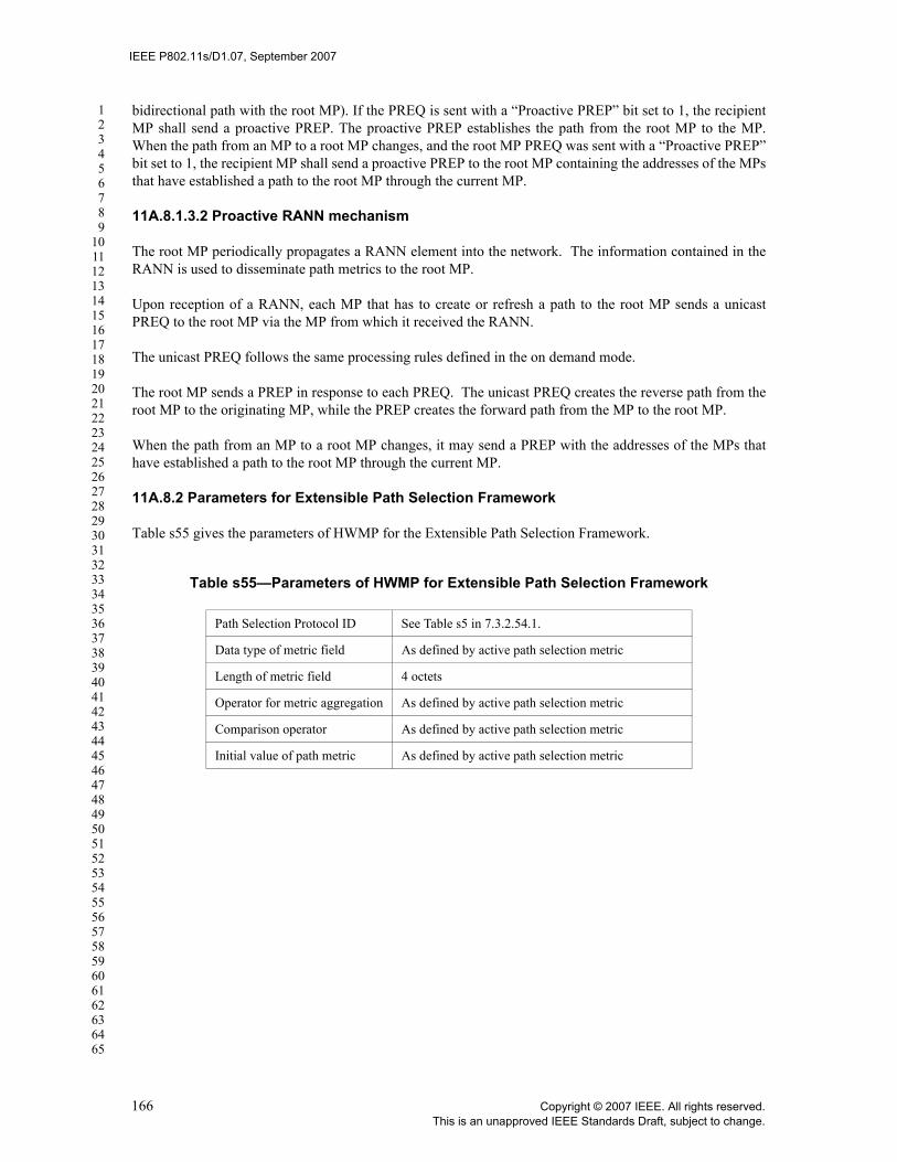
IEEE P802.11s/D1.07, September 2007
123456789
1011121314151617181920212223242526272829303132333435363738394041424344454647484950515253545556575859606162636465
bidirectional path with the root MP). If the PREQ is sent with a “Proactive PREP” bit set to 1, the recipientMP shall send a proactive PREP. The proactive PREP establishes the path from the root MP to the MP.When the path from an MP to a root MP changes, and the root MP PREQ was sent with a “Proactive PREP”bit set to 1, the recipient MP shall send a proactive PREP to the root MP containing the addresses of the MPsthat have established a path to the root MP through the current MP.
11A.8.1.3.2 Proactive RANN mechanism
The root MP periodically propagates a RANN element into the network. The information contained in theRANN is used to disseminate path metrics to the root MP.
Upon reception of a RANN, each MP that has to create or refresh a path to the root MP sends a unicastPREQ to the root MP via the MP from which it received the RANN.
The unicast PREQ follows the same processing rules defined in the on demand mode.
The root MP sends a PREP in response to each PREQ. The unicast PREQ creates the reverse path from theroot MP to the originating MP, while the PREP creates the forward path from the MP to the root MP.
When the path from an MP to a root MP changes, it may send a PREP with the addresses of the MPs thathave established a path to the root MP through the current MP.
11A.8.2 Parameters for Extensible Path Selection Framework
Table s55 gives the parameters of HWMP for the Extensible Path Selection Framework.
Table s55—Parameters of HWMP for Extensible Path Selection Framework
Path Selection Protocol ID See Table s5 in 7.3.2.54.1.
Data type of metric field As defined by active path selection metric
Length of metric field 4 octets
Operator for metric aggregation As defined by active path selection metric
Comparison operator As defined by active path selection metric
Initial value of path metric As defined by active path selection metric
166 Copyright © 2007 IEEE. All rights reserved.This is an unapproved IEEE Standards Draft, subject to change.

IEEE P802.11s/D1.07, September 2007
123456789
1011121314151617181920212223242526272829303132333435363738394041424344454647484950515253545556575859606162636465
11A.8.3 Definitions
This subclause describes terminology for HWMP. Figure s65 illustrates an example utilizing this terminol-ogy.
Figure s65—Illustration of definitions
The following definitions are made within the context of a single PREQ/PREP action frame pair (path dis-covery).
— path originator: The path originator is the MP that triggers the path discovery. — path originator address: The MAC address of the path originator.— path target: The path target is the MP to which the path originator attempts to establish a path. — path target address: The MAC address of the path target.— intermediate MP: The intermediate MP is the MP which participates in path selection and is neither
path originator nor path target.— intermediate MP address: The MAC address of the intermediate MP.— forward path: The forward path is the path to the path target, set up at the path originator and inter-
mediate MPs. — reverse path: The reverse path is the path to the path originator, set up at the path target and inter-
mediate MPs.— forwarding information: The forwarding information maintained by an intermediate MP that
allows the MP to perform its path selection and forwarding functions. The terminology used when discussing Forwarding Information is relative to the MP (reference MP)and a particular destination of the path. The following terms are specific to a given instance of theForwarding Information.:
—destination MP: The end point of a path. —destination MP address: The MAC address of the path destination.—next hop MP: The next hop MP is a peer MP on the path to the destination MP. —next hop MP address: The MAC address of the next hop MP.—precursor MP: A precursor MP is an MP that identifies a given MP as the next hop MP to
some destination MP.—precursor MP address: The MAC address of the precursor MP.
Table s56 shows the roles of the various MPs in the Forward Path and Reverse Path generated as a result ofthe full path PREQ/PREP processing as shown in Figure s65. Each row in the table contains the roles of aforward/reverse path from the reference MP’s perspective.
Forward Path
Reverse Path
PathOriginator
Intermediate1
Intermediate2
Intermediate3
PathTarget
Forward Path
Reverse Path
PathOriginator
Intermediate1
Intermediate2
Intermediate3
PathTarget
Copyright © 2007 IEEE. All rights reserved. 167This is an unapproved IEEE Standards Draft, subject to change.

IEEE P802.11s/D1.07, September 2007
123456789
1011121314151617181920212223242526272829303132333435363738394041424344454647484950515253545556575859606162636465
— unknown destination: A destination MP is considered unknown if the MP does not have any for-warding information for that MP.
— unreachable destination: A destination MP is considered unreachable if the MP does not have validforwarding information for that MP.
— destination sequence number (DSN): The sequence number of the MP when the MP is referred toas the destination. The destination sequence number is used to distinguish newer from older for-warding information to the destination MP. See also 11A.8.4.2.
— target sequence number: The sequence number of the MP when the MP is referred to as the pathtarget. It is only used in PREQ/PREP during the establishment of the path.
— time-to-live (TTL): An integer number that is used to limit the number of hops an HWMP Informa-tion Element may be processed and propagated. Note that this TTL is not related to the TTL in themesh header (see 7.1.3.5a).
— root MP: A root MP is the root of a path selection tree.— dependent MP: An MP that has a Next Hop MP on the path to the Root MP.
11A.8.4 General rules for processing HWMP information elements
This subclause describes the rules for the processing of the following components of the HWMP information elements:
— Destination Sequence Number— TTL— Metric
Note: It is assumed that the receiving MP only accepts HWMP elements from MPs with which it has estab-lished a secure link. Therefore, all HWMP elements accepted are presumed to have originated in the samemesh network that the receiving MP belongs to.
Table s56—Precursor and Next Hop Examples
Forward Path (to Path Target)
Reference MP Precursor MP Next Hop MP Destination MP
Path Originator N/A Intermediate 1 Path Target
Intermediate 2 Intermediate 1 Intermediate 3 Path Target
Path Target Intermediate 3 N/A Path Target
Reverse Path (to Path Originator)
Reference MP Precursor MP Next Hop MP Destination MP
Path Originator Intermediate 2 N/A Path Originator
Intermediate 2 Intermediate 3 Intermediate 1 Path Originator
Path Target N/A Intermediate 3 Path Originator
168 Copyright © 2007 IEEE. All rights reserved.This is an unapproved IEEE Standards Draft, subject to change.

IEEE P802.11s/D1.07, September 2007
123456789
1011121314151617181920212223242526272829303132333435363738394041424344454647484950515253545556575859606162636465
11A.8.4.1 HWMP propagation
Many HWMP information elements are intended to be processed and propagated across a mesh by MPs.Each propagation is subject to certain rules or limitations as explained in the following subclauses. Certainparameters in the HWMP information elements are updated during the propagation. See 11A.8.8, 11A.8.5,11A.8.6, and 11A.8.7.
The originator of an HWMP information element sets the initial value of TTL. The MP which receives theHWMP information element shall propagate it if the TTL value is greater than zero. Before propagating theHWMP information element, the MP decrements the TTL value.
In general, the propagation of an HWMP information element is not subject to a delay. Exception exists forthe RANN information element as described in 11A.8.8.
11A.8.4.2 Destination Sequence Number (DSN)
The DSN is included in the RANN, PREQ or PREP information elements. The DSN is updated whenever anMP receives new (i.e. not stale) information about the sequence number from a PREQ, PREP or PERR thatmay be received related to that destination MP. HWMP depends on each MP in the network to own andmaintain its destination sequence number to guarantee the loop-freedom of all paths towards that MP. A des-tination MP increments its own sequence number in two circumstances:
— Immediately before an MP originates a path discovery, it shall increment its own sequence number.This prevents conflicts with previously established reverse paths towards the originator of a PREQ.
— Immediately before a destination MP originates a PREP in response to a PREQ, it shall update itsown sequence number to the maximum of its current sequence number and the destination sequencenumber in the PREQ.
Sequence numbers are processed as follows:
a) Sequence numbers are incremented as unsigned integers.
b) When checking the freshness of received path information, the receiving MP compares its value ofthe stored sequence number with that in the incoming HWMP element using signed 32-bit arith-metic. This is necessary to assure correct results if the sequence number rolls over (changes to zero).If the result of subtracting the stored sequence number from the incoming sequence number is lessthan zero, then the information in the HWMP element is stale and shall not be processed.
In general, when an MP receives an information element with a DSN that is less than the last received DSNfor that originator, it discards the received information element. If they are the same, the outcome (informa-tion element processed or not) depends on the type of the information element and some additional condi-tions. These cases are noted in the applicable information element descriptions.
The only other circumstance in which an MP may change the destination sequence number in one of its for-warding information entries is in response to a lost or expired link to the next hop towards that destinationMP. The MP determines which destinations use a particular next hop by consulting its forwarding informa-tion. In this case, for each destination that uses the next hop, the MP increments the sequence number andmarks the path as invalid (see also 11A.8.7). Whenever any forwarding information containing a sequencenumber at least equal to the recorded sequence number for an affected destination is received by an MP thathas marked that forwarding information as invalid, the MP shall update its forwarding information accord-ing to the information contained in the update.
An MP may change the sequence number in the forwarding information of a destination MP if the link to theNext Hop MP towards the destination MP breaks.
Copyright © 2007 IEEE. All rights reserved. 169This is an unapproved IEEE Standards Draft, subject to change.

IEEE P802.11s/D1.07, September 2007
123456789
1011121314151617181920212223242526272829303132333435363738394041424344454647484950515253545556575859606162636465
11A.8.4.3 Metric of last link
The term metric of last link specifies the current link metric between the transmitter of the information ele-ment under consideration and the MP that received this information element. The latter is the MP under con-sideration.
11A.8.4.4 Forwarding information
The forwarding information consists of at least a destination MP address, the Destination Sequence Number(DSN), the Next Hop address, the path metric, the precursor list, and the lifetime of this forwarding informa-tion. Stored forwarding information can be active and inactive. The latter means that the forwarding infor-mation is still known for future reference but not used for forwarding. The Forwarding Information becomesinactive when either the MP receives a RERR regarding the destination MP or the information is no longeractive according to the lifetime.
11A.8.4.5 Creation and update of forwarding information
HWMP path selection information elements create or update the forwarding information in the MPs thatprocess these information elements. The creation and update of forwarding information follows the samerules for PREQ, PREP, and RANN. These rules are given below. Unless otherwise noted, the term“HWMP_IE” stands for the information element under consideration (PREQ, PREP, or RANN). In the fol-lowing text, the “ ” indicates an entry into the local forwarding data base, i.e., the path selection table.
1) If the MP does not have any valid forwarding information to the originator of the HWMP_IE (hwmp_ie.originator_address), the value of the destination sequence number is set to hwmp_ie.destination_sequence_number (field: destination_sequence_number), it creates this information from the field hwmp_ie.originator_address (field: destination), the transmitter address of the management frame containing the HWMP_IE (field: next hop), the accumulation of the value of field hwmp_ie.metric with the metric of the last link (field: path metric), and the value of field hwmp_ie.lifetime (field: lifetime).
2) If the MP does not have any valid forwarding information to the transmitter of the HWMP_IE, it creates this information from the transmitter address of the management frame containing the HWMP_IE (field: destination and next hop), the destination sequence number is set to invalid, the metric of the last link (field: path metric), and the value of field hwmp_ie.lifetime (field: lifetime).
3) If the MP has valid forwarding information to the originator of the HWMP_IE (hwmp_ie.originator_address), and the acceptance criteria of the corresponding element as described in 11A.8.8.3.1, 11A.8.5.3.1, 11A.8.6.3.1, 11A.8.7.3.1 are satisfied, then the MP updates this forwarding information with the transmitter address of the management frame containing the HWMP_IE (field: next hop), the value of the destination sequence number is set to hwmp_ie.destination_sequence_number (field: destination_sequence_number), the accumulation of the value of field hwmp_ie.metric with the metric of the last link (field: path metric), and the larger one of the lifetime of the stored forwarding information and the value of field hwmp_ie.lifetime (field: lifetime).
4) If the MP has valid forwarding information to the transmitter of the HWMP_IE and if the path metric of this information is worse than the metric of the last link, then the MP updates this forwarding information with the transmitter address of the management frame containing the HWMP_IE (field: next hop), the destination sequence number is set to invalid, the metric of the last link (field: path metric), and the larger one of the lifetime of the stored forwarding information and the value of field hwmp_ie.lifetime (field: lifetime).
170 Copyright © 2007 IEEE. All rights reserved.This is an unapproved IEEE Standards Draft, subject to change.

IEEE P802.11s/D1.07, September 2007
123456789
1011121314151617181920212223242526272829303132333435363738394041424344454647484950515253545556575859606162636465
11A.8.4.6 Repeated attempts at path discovery
EDITORIAL NOTE—This text moved from “Note 1” in PREQ clause, per CID 1446
Repeated attempts by an MP at path discovery towards a given (set of) destination(s) shall be limited todot11MeshHWMPmaxPREQretries and utilize a binary exponential backoff between transmissions. Theminimum waiting time for the PREP corresponding to a PREQ is 2 *dot11MeshHWMPnetDiameterTraversalTime.
11A.8.4.7 Rate of sequence number changes
In order to improve path stability (and further reduce overhead), an MP may use the same Originator Desti-nation Sequence Number (Originator DSN) for a certain time interval. The Originator DSN shall be incre-mented only after at least dot11MeshHWMPnetDiameterTraversalTime has elapsed since the previousincrement. This mechanism prevents MPs from changing the path frequently to the source every time thesource sends a burst of PREQs within a very short time. This element of the protocol allows a source MP toimmediately initiate on-demand path discovery to a new destination without affecting recently refreshedpaths to the source in other MPs.
11A.8.5 Path Request (PREQ)
This subclause describes the function, generation and processing of the Path Request information element.
11A.8.5.1 Function
The Path Request (PREQ) element, described in 7.3.2.70, is used for three purposes:— Discovering a path to one or more destinations— Building a proactive (reverse) path selection tree to the root MP— Confirming a path to a destination (optional)
11A.8.5.2 Conditions for generating and sending a PREQ
An MP shall send a PREQ element in a PREQ frame in the following cases:
Case A: Original Transmission (Path Discovery)All of the following applies:
• The MP needs to establish an on-demand path to one or more destination MPs or the proxy of agiven destination for which there is no ongoing path discovery initiated by this MP.
• The MP has not sent a PREQ element less than dot11MeshHWMPpreqMinInterval TUs ago. Ifthis is the case, the transmission of the PREQ has to be postponed until this condition becomestrue.
• The MP has not made more than (dot11MeshHWMPmaxPREQretries – 1) repeated attempts atpath discovery towards the destination of the PREQ.
The content of a PREQ element in Case A shall be as shown in Table s57.
Table s57—Content of a PREQ element in Case A
Field Value
ID Value given in Table 7-26 for the PREQ element
Copyright © 2007 IEEE. All rights reserved. 171This is an unapproved IEEE Standards Draft, subject to change.

IEEE P802.11s/D1.07, September 2007
123456789
1011121314151617181920212223242526272829303132333435363738394041424344454647484950515253545556575859606162636465
Case B: Original Transmission (Path Maintenance) (optional implementation enhancement)
All of the following applies:• the MP has a path to a given destination that is not a Root MP
• the last PREQ to this destination was sent dot11MeshHWMPmaintenanceInterval TUs (or more)ago.
The content of a PREQ in Case B shall be as shown in Table s58.
Length 27 + N*11
Flags Bit 0: 0 (no portal role) Bit 1: 0 (broadcast)Bit 2: 0 (no proactive PREP applicable)Bit 3 – 5: ReservedBit 6: Address Extension (AE) (1=if (destination_count=1 and prox-ied address present), 0=otherwise)Bit 7: Reserved
Hop Count 0
Time to Live Maximum number of hops allowed for this information element, e.g., HWMP_NET_DIAMETER.
PREQ ID Previous PREQ ID + 1
Originator Address MAC address of the originator of the PREQ
Originator’s Destination Sequence Number
Previous Originator DSN + 1. See Note 2
Proxied Address Present only if Bit 6 in Flags = 1. This value is set to the proxied address which is the source of the frame.
Lifetime The time for which MPs receiving the PREQ consider the forwarding information to be valid, e.g. dot11MeshHWMPactivePathTimeout.
Metric Initial value of active path selection metric
Destination Count (N)
Per Destination Flags The DO flag is set to dot11MeshHWMPDestinationOnly and the RF flag is set to dot11MeshHWMPReplyAndForward
Destination Address MAC address of requested destination
Destination Sequence Number The latest sequence number received in the past by the originator for any path towards the destination.
Table s58—Content of a PREQ element in Case B
Field Value
ID Value given in Table 7-26 for the PREQ element
Length As required
Table s57—Content of a PREQ element in Case A
172 Copyright © 2007 IEEE. All rights reserved.This is an unapproved IEEE Standards Draft, subject to change.
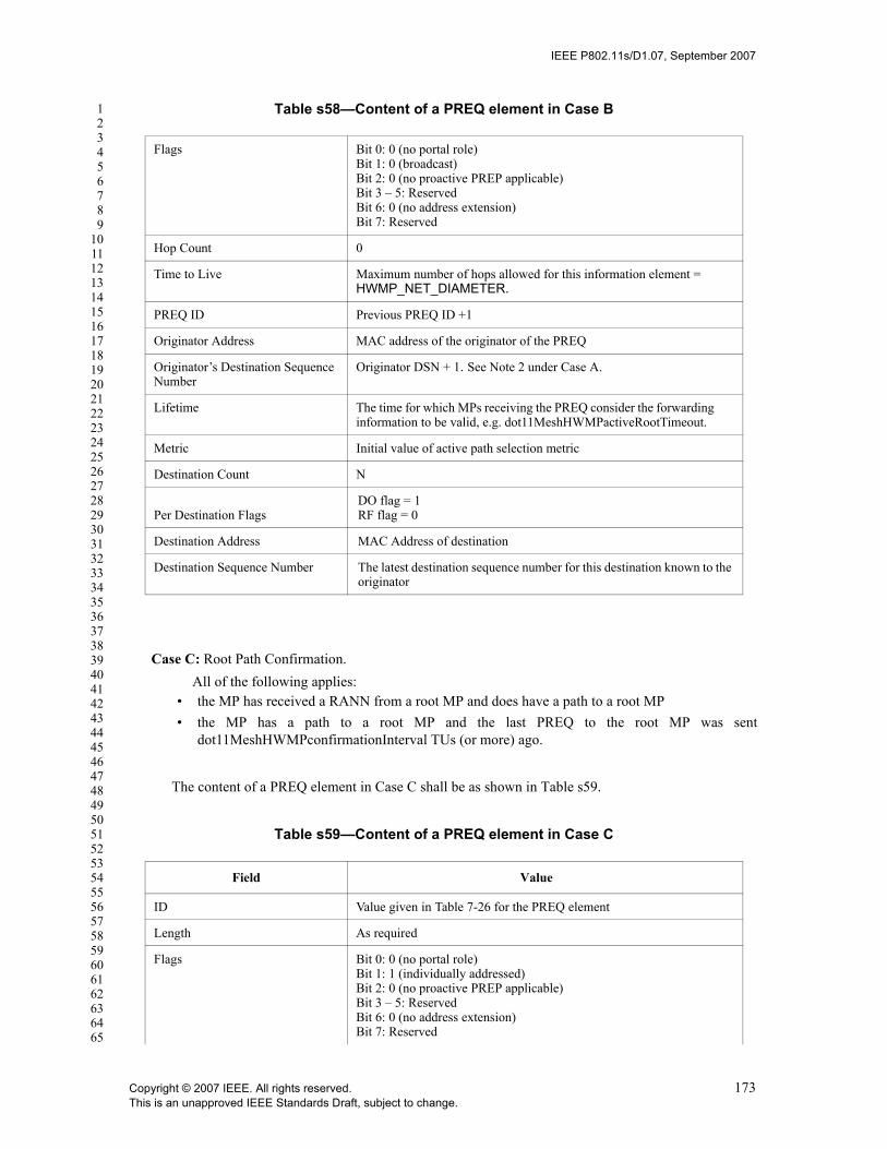
IEEE P802.11s/D1.07, September 2007
123456789
1011121314151617181920212223242526272829303132333435363738394041424344454647484950515253545556575859606162636465
Case C: Root Path Confirmation.All of the following applies:
• the MP has received a RANN from a root MP and does have a path to a root MP • the MP has a path to a root MP and the last PREQ to the root MP was sent
dot11MeshHWMPconfirmationInterval TUs (or more) ago.
The content of a PREQ element in Case C shall be as shown in Table s59.
Flags Bit 0: 0 (no portal role) Bit 1: 0 (broadcast)Bit 2: 0 (no proactive PREP applicable)Bit 3 – 5: ReservedBit 6: 0 (no address extension)Bit 7: Reserved
Hop Count 0
Time to Live Maximum number of hops allowed for this information element = HWMP_NET_DIAMETER.
PREQ ID Previous PREQ ID +1
Originator Address MAC address of the originator of the PREQ
Originator’s Destination Sequence Number
Originator DSN + 1. See Note 2 under Case A.
Lifetime The time for which MPs receiving the PREQ consider the forwarding information to be valid, e.g. dot11MeshHWMPactiveRootTimeout.
Metric Initial value of active path selection metric
Destination Count N
Per Destination FlagsDO flag = 1RF flag = 0
Destination Address MAC Address of destination
Destination Sequence Number The latest destination sequence number for this destination known to the originator
Table s59—Content of a PREQ element in Case C
Field Value
ID Value given in Table 7-26 for the PREQ element
Length As required
Flags Bit 0: 0 (no portal role) Bit 1: 1 (individually addressed)Bit 2: 0 (no proactive PREP applicable)Bit 3 – 5: ReservedBit 6: 0 (no address extension)Bit 7: Reserved
Table s58—Content of a PREQ element in Case B
Copyright © 2007 IEEE. All rights reserved. 173This is an unapproved IEEE Standards Draft, subject to change.

IEEE P802.11s/D1.07, September 2007
123456789
1011121314151617181920212223242526272829303132333435363738394041424344454647484950515253545556575859606162636465
Case D: PREQ ForwardingCase D1 (destination count = 1, no PREP generation): All of the following applies:
• the MP has received and accepted a PREQ – See 11A.8.5.3.1• Destination_count = 1• the MP is not the destination of the PREQ OR the destination of the PREQ is the MAC broadcast
address (all 1’s)• the MP is not the proxy of the destination address• the MP has no valid forwarding information for the requested destination• [Destination Only flag of the destination in the PREQ is ON (DO = 1)]
OR[{Destination Only flag of the destination in the PREQ is OFF (DO = 0)} AND {MP has noactive forwarding information for the requested destination preq.destination_address}]
The content of a PREQ element in Case D1 shall be as shown in Table s60.
Hop Count 0
Time to Live 1
PREQ ID Not used
Originator Address MAC address of the originator of the PREQ
Originator’s Destination Sequence Number
Originator DSN + 1. See Note 2 under Case A.
Lifetime The time for which MPs receiving the PREQ consider the forwarding information to be valid, e.g. HWMP_ACTIVE_ROOT_TIMEOUT.
Metric Initial value of active path selection metric
Destination Count 1
Per Destination Flags DO flag = 1, RF flag = 0
Destination Address Root MP MAC Address
Destination Sequence Number The latest destination sequence number for this destination known to the originator
Table s60—Content of a PREQ element in Case D1
Field Value
ID Value given in Table 7-26 for the PREQ element
Length 37
Flags As received
Hop Count As received + 1
Time to Live As received – 1
Table s59—Content of a PREQ element in Case C
174 Copyright © 2007 IEEE. All rights reserved.This is an unapproved IEEE Standards Draft, subject to change.

IEEE P802.11s/D1.07, September 2007
123456789
1011121314151617181920212223242526272829303132333435363738394041424344454647484950515253545556575859606162636465
Case D2 (destination count = 1, PREP generation as intermediate MP): All of the following applies:
• the MP has received and accepted a PREQ – See 11A.8.5.3.1• preq.destination_count = 1• the MP is not the destination of the PREQ• the MP has active forwarding information for the requested destination preq.destination_address• Destination Only flag of the destination in the PREQ is OFF (DO = 0)• Reply and Forward flag of the destination in the PREQ is ON (RF = 1)
The contents of a PREQ element in Case D2 shall be as shown in Table s61.
PREQ ID As received
Originator Address As received
Originator’s Sequence Number As received
Proxied Address As received. This field is only present if Bit 6 of the Flags field (AE flag) is set to 1.
Lifetime As received
Metric As received own metric toward transmitter of received PREQ
Destination Count 1
Per Destination flags #1 As received
Destination MAC address #1 As received
Destination Sequence Number #1 As received
Table s61—Contents of a PREQ element in Case D2
Field Value
ID Value given in Table 7-26 for the PREQ element
Length 37
Flags As received
Hop Count As received + 1
Time to Live As received – 1
PREQ ID As received
Originator Address As received
Originator’s Sequence Number As received
Proxied Address As received. This field is only present if Bit 6 of the Flags field (AE flag) is set to 1.
Lifetime As received
Table s60—Content of a PREQ element in Case D1
⊕
Copyright © 2007 IEEE. All rights reserved. 175This is an unapproved IEEE Standards Draft, subject to change.

IEEE P802.11s/D1.07, September 2007
123456789
1011121314151617181920212223242526272829303132333435363738394041424344454647484950515253545556575859606162636465
Case D3 (destination count > 1): All of the following applies• the MP has received and accepted a PREQ – See 11A.8.5.3.1• there is at least one requested destination left after processing the PREQ according to 11A.8.5.3.
The contents of a PREQ element in Case D3 shall be as shown in Table s62.
Metric As received own metric toward transmitter of received PREQ
Destination Count 1
Per Destination flags #1 Bit 0 (DO): 1 (set to 1 before forwarding because MP sent a PREP)Bit 1 (RF): As received
Destination MAC address #1 As received
Destination Sequence Number #1 As received
Table s62—Contents of a PREQ element in Case D3
Field Value
ID Value given in Table 7-26 for the PREQ element
Length 26 + N * 11
Flags As received
Hop Count As received + 1
Time to Live As received – 1
PREQ ID As received
Originator Address As received
Originator’s Sequence Number As received
Lifetime As received
Metric As received own metric toward the transmitter of the received PREQ
Destination Count 1 ≤ destination count ≤ received destination count
received destination count less the number of requesteddestinations, for which the processing MP
— is the destination or — has active forwarding information for the requested
destination and the corresponding Destination Onlyflag is off (DO=0) and Reply and Forward flag is on(RF = 1)
Per Destination Flags #A As received
Destination MAC address #A As received
Table s61—Contents of a PREQ element in Case D2
⊕
⊕
176 Copyright © 2007 IEEE. All rights reserved.This is an unapproved IEEE Standards Draft, subject to change.

IEEE P802.11s/D1.07, September 2007
123456789
1011121314151617181920212223242526272829303132333435363738394041424344454647484950515253545556575859606162636465
For the per destination fields (per destination flags, destination MAC address, destination sequence number)assume the following:
— destination #A: If destination A would have been the only requested destination, it would generate aPREQ for forwarding according to case D1.
— destination #B: If destination B would have been the only requested destination, it would generate aPREQ for forwarding according to case D2.
Case E: Proactive PREQ (original transmission)All of the following applies:
• The Root MP is configured to send proactive root PREQs • The Root Announcement interval has expired
The contents of a PREQ in Case E shall be as shown in Table s63.
Destination Sequence Number #A As received
Per Destination Flags #B Bit 0 (DO): 1 (set to 1 because MP sent PREP)Bit 1 (RF): As received
Destination MAC address #B As received
Destination Sequence Number #B As received
Table s63—Contents of a PREQ in Case E
Field Value
ID Value given in Table 7-26 for the PREQ element
Length 37
Flags Bit 0: As needed (portal role) Bit 1: 0 (broadcast)Bit 2: As needed (proactive PREP)Bit 3 – 5: ReservedBit 6: 0 (no address extension)Bit 7: Reserved
Hop Count 0
Time to Live Maximum number of hops allowed for this information element, e.g. HWMP_NET_DIAMETER.
PREQ ID Previous PREQ ID + 1
Originator Address root MP MAC address
Originator’s Destination Sequence Number
Previous DSN of root MP + 1
Lifetime dot11MeshHWMPpathToRootInterval
Metric Initial value of active path selection metric
Table s62—Contents of a PREQ element in Case D3
Copyright © 2007 IEEE. All rights reserved. 177This is an unapproved IEEE Standards Draft, subject to change.

IEEE P802.11s/D1.07, September 2007
123456789
1011121314151617181920212223242526272829303132333435363738394041424344454647484950515253545556575859606162636465
11A.8.5.3 PREQ processing
Received PREQ elements are subject to certain acceptance criteria. Processing and actions taken depend on the contents of the PREQ and the information available to the receiving MP.See also 11A.8.4: General rules for message processing
11A.8.5.3.1 Acceptance criteria
The PREQ element shall not be accepted (and shall not be processed as described in 11A.8.5.3.2) if any of the following is true:
— The Originator DSN < previous Originator DSN
— (DSN = previous DSN) AND (updated path metric is worse than previous path metric)
— (the destination address of the PREQ is neither the recipient MAC address nor a MAC address prox-ied by the recipient) AND (dot11MeshForwarding is set to 0)
Otherwise, the PREQ information element is accepted.
See also 11A.8.4: General rules for message processing
11A.8.5.3.2 Effect of receipt
The following applies only to a PREQ element that was accepted according to the acceptance criteria in 11A.8.5.3.1:
1. The receiving MP shall record the PREQ ID, the Originator Address, and entries for each destination MAC Address and DSN
2. The receiving MP shall update the active forwarding information it maintains for the originator and previous hop MPs of the PREQ (see 11A.8.4.5)
3. If the MP is addressed by the PREQ or is the proxy of the destination MAC address it shall initiate the transmission of a PREP to the originator (11A.8.6.2 Case A). If the PREQ carries a proxied address (indicated by the AE flag), the MP shall update its proxy information with the proxied address and set the PREQ originator address as the corresponding proxy.
4. If step 3 was not applicable for the MP and the AE flag in the PREQ is set to 1, the MP may update its proxy information with the proxied address and set the PREQ originator address as the corresponding proxy.
Destination Count 1
Per Destination Flags DO = 1, RF = 1
Destination Address Broadcast address
Destination Sequence Number 0
Table s63—Contents of a PREQ in Case E
178 Copyright © 2007 IEEE. All rights reserved.This is an unapproved IEEE Standards Draft, subject to change.

IEEE P802.11s/D1.07, September 2007
123456789
1011121314151617181920212223242526272829303132333435363738394041424344454647484950515253545556575859606162636465
5. If the MP has valid forwarding information to any of the requested destinations and the DO flag for such a destination is OFF (DO=0), it initiates the transmission of a PREP to each of these destinations (see 11A.8.6.2 Case A)
6. If there are destinations in the PREQ that have been not processed in steps 3 or 4 or that have been processed in step 4 but the corresponding Reply and Forward Flag is ON (RF = 1), the receiving MP shall forward the PREQ as defined in 11A.8.5.2, Case D.
7. If the MP is initiating a PREP transmission on behalf of another destination (intermediate reply), it should update its forwarding information by placing the last hop MP (from which it received the PREQ) into the precursor list for the forward path entry for the destination. In addition, this intermediate MP also updates its forwarding information for the MP originating the PREQ by placing the next hop toward the destination in the precursor list for the reverse path entry.
11A.8.6 Path Reply (PREP)
This subclause describes the function, generation and processing of the Path Reply information element.
11A.8.6.1 Function
The Path Reply (PREP) element is transmitted in individually addressed frames and is described in 7.3.2.71. The purpose of the PREP is:
— to confirm the forward path to a destination and— to establish a reverse path to the originator.
11A.8.6.2 Conditions for generating and sending a PREP
An MP sends out a PREP element in a PREP frame in the following cases:
Case A: Original transmissionA PREP is transmitted if the MP has received a PREQ fulfilling all of the following conditions:
a. One of the following applies:o The Destination Address of the PREQ is the same as MAC address of the receiving
MP o The Destination Address of the PREQ = all 1’s (broadcast) and the PREP flag is set to
1 (”Proactive PREP”)o The Destination Address of the PREQ is currently proxied by the MP
b. One of the following applies:o The Originator DSN of the PREQ (preq.orig_dsn) is greater than the DSN of the last
PREQ received from the same originator address (that includes the case that there is no path to the originating MP)
o The Metric is better than the path selection metric currently associated with the Originator Address and the Originator DSN of the PREQ (preq.orig_dsn) is equal to the DSN of the last PREQ received from the same originator address
The content of the generated PREP in Case A shall be as shown in Table s64.Note: the DA of the action frame carrying the PREP element is set to the address of the next hop to the Originator Address of the PREQ that triggered the PREP.
Case B: PREP Propagation
Copyright © 2007 IEEE. All rights reserved. 179This is an unapproved IEEE Standards Draft, subject to change.

IEEE P802.11s/D1.07, September 2007
123456789
1011121314151617181920212223242526272829303132333435363738394041424344454647484950515253545556575859606162636465
A PREP is propagated if all of the following applies:1. the MP has received and accepted the PREP – See 11A.8.6.3.12. the MP is not the destination of the PREP
The contents of a PREP element in Case B shall be as shown in Table s65.
Table s64—Contents of a PREP element in Case A
Field Value
ID Value given in Table 7-26 for the PREP element
Length As required
Flags Bit 0 – 5: ReservedBit 6: Address Extension (AE) (1 = proxied device address present, 0 = otherwise)Bit 7: Reserved
Hop Count 0
Time to Live Maximum number of hops allowed for this element
Destination Address MAC address of the originator of the PREP
Destination Sequence Number Sequence number of the target of the PREQ after it has been incre-mented
Destination Proxied Address Proxied address on behalf of which the PREP is sent. Present only if Bit 6 (AE) in Flags = 1.
Lifetime As per the PREQ that triggered the transmission of this PREQ
Metric Initial value of active path selection metric
Originator Address MAC address of the originator (of the PREQ)
Originator Sequence Number Sequence number of the originator (of the PREQ)
Dependent MP Count N N
Dependent MP MAC Address # MAC address of dependent MP
Dependents MP DSN # Destination sequence number associated with the MAC address of the dependent MP.
Table s65—Contents of a PREP element in Case B
Field Value
ID Value given in Table 7-26 for the PREP ele-ment
Length As received
Flags As received
Hop Count As received + 1
Time to Live As received – 1
Destination Address As received
180 Copyright © 2007 IEEE. All rights reserved.This is an unapproved IEEE Standards Draft, subject to change.

IEEE P802.11s/D1.07, September 2007
123456789
1011121314151617181920212223242526272829303132333435363738394041424344454647484950515253545556575859606162636465
Note: the DA of the action frame carrying the PREP element is set to the address of the next hop to the Originator Address of the PREQ that triggered the PREP.
Case C: Intermediate replyA PREP is transmitted if the MP has received a PREQ fulfilling all of the following conditions:
1. The PREQ Destination Only flag is set to 02. The receiving MP has active forwarding information with:
a. A destination that is the same as the Destination Address of the PREQ b. A DSN that is greater than or equal to the DSN of the PREQ (preq.dest_dsn)c. A non-zero lifetime
The content of the generated PREP in Case C shall be as shown in Table s66.
Destination Sequence Number As received
Destination Proxied Address As received
Lifetime As received
Metric As received own metric toward the trans-mitting MP
Originator Address MAC address of the originator (of the PREQ)
Originator Sequence Number Sequence number of the originator (of the PREQ)
Dependent MP Count N N
Dependent MP MAC Address # MAC address of the dependent MP
Dependent MP DSN # Destination sequence number associated with the MAC address of the dependent MP
Table s66—Contents of a PREP element in Case C
Field Value
ID Value given in Table 7-26 for the PREP element
Length As required
Flags Bit 0: 0Bits 1– 7: Reserved
Hop Count 0
Time to Live Maximum number of hops allowed for this element
Destination Address Destination MAC address from the PREQ
Destination Sequence Number DSN of the stored forwarding information of the Destination MAC address of the PREQ
Destination Proxied Address As received
Table s65—Contents of a PREP element in Case B
⊕
Copyright © 2007 IEEE. All rights reserved. 181This is an unapproved IEEE Standards Draft, subject to change.

IEEE P802.11s/D1.07, September 2007
123456789
1011121314151617181920212223242526272829303132333435363738394041424344454647484950515253545556575859606162636465
Case D: PREP in Proactive PREP modeAll of the following applies:
— The MP has received a PREQ broadcast with the “Proactive PREP” flag set to 0.
— The MP needs the root MP to establish a path to itself
The content of the generated PREP in Case D shall be as shown in Table s67.
Lifetime As per the PREQ that triggered the transmission of this PREQ
Metric Value of path metric taken from the active forwarding information for the destination address of the PREQ
Originator Address MAC address of the originator (of the PREQ)
Originator Sequence Number Sequence number of the originator (of the PREQ)
Dependent MP Count N N
Dependent MP MAC Address # MAC address of the dependent MP
Dependent MP DSN # Destination sequence number associated with the MAC address of the dependent MP
Table s67—Contents of a PREP element in Case D
Field Value
ID Value given in Table 7-26 for the PREP element
Length As required
Flags Bit 0: 0Bits 1– 7: Reserved
Hop Count 0
Time to Live Maximum number of hops allowed for this element
Destination Address MAC address of the originator of the PREP
Destination Sequence Number DSN of the originator of the PREP
Destination Proxied Address 0
Lifetime As per the PREQ that triggered the transmission of this PREQ
Metric Initial value of active path selection metric
Originator Address MAC address of the originator (of the PREQ)
Originator Sequence Number Sequence number of the originator (of the PREQ)
Dependent MP Count N N
Dependent MP MAC Address # MAC address of the dependent MP
Dependent MP DSN # Destination sequence number associated with the MAC address of the dependent MP
Table s66—Contents of a PREP element in Case C
182 Copyright © 2007 IEEE. All rights reserved.This is an unapproved IEEE Standards Draft, subject to change.

IEEE P802.11s/D1.07, September 2007
123456789
1011121314151617181920212223242526272829303132333435363738394041424344454647484950515253545556575859606162636465
11A.8.6.3 PREP processing
Received PREP elements are subject to certain acceptance criteria. Processing and actions taken depend on the contents of the PREP and the information available to the receiving MP.
11A.8.6.3.1 Acceptance criteria
The PREP element shall not be accepted (and shall not be processed as described in 11A.8.6.3.2) if any of the following is true:
— The DSN < previous DSN from this originator— The Time to Live is 1 or less— (the destination address of the PREQ is neither the recipient MAC address nor a MAC address prox-
ied by the recipient) AND (dot11MeshForwarding is set to 0)
11A.8.6.3.2 Effect of receipt
The following applies only to a PREP alement that was accepted according to the acceptance criteria in 11A.8.6.3.1.
1) The receiving MP shall record the Originator Address, together with the DSN, hopcount and metric according to the rules defined in 11A.8.4.5.
2) The receiving MP may record the list of dependent MPs if present in the PREP.3) If the receiving MP is not the final destination of the PREP, the PREP is propagated as per Case B
above.4) If the receiving MP is the final destination of the PREP and the AE-flag is set, the MP shall store the
proxy information with the destination proxied address and shall set the corresponding proxy as the destination MP address.
5) If the receiving MP is not the final destination of the PREP and the AE-flag is set, the MP may store the proxy information with the destination proxied address and sets the corresponding proxy as the destination MP address.
6) If the MP propagates the PREP, the precursor list for the Destination Address is updated by adding the next hop MP to which the PREP is propagated. In addition, at the MP the precursor list for the originator address is updated by adding the next hop MP towards the Destination Address.
11A.8.7 Path Error information element (PERR)
This subclause describes the function, generation and processing of the path error information element.
11A.8.7.1 Function
The PERR information element is used for announcing a broken link to all traffic sources that have an activepath over this broken link. The active forwarding information associated with the unreachable destinationsshould no longer be used for forwarding.
A PERR element may be either broadcast (if there are many precursors), unicast (if there is only one precur-sor), or iteratively unicast to all precursors depending on the size of precursor list for the destinations. ThePERR element should contain those destinations that are part of the created list of unreachable destinationsand have a non-empty precursor list. The peer MPs that should receive the PERR are all those that belong toa precursor list of at least one of the unreachable destination(s) in the newly created PERR.
Copyright © 2007 IEEE. All rights reserved. 183This is an unapproved IEEE Standards Draft, subject to change.

IEEE P802.11s/D1.07, September 2007
123456789
1011121314151617181920212223242526272829303132333435363738394041424344454647484950515253545556575859606162636465
A PERR information element is propagated by MPs receiving a PERR if certain conditions are fulfilled.
An MP generating or receiving a PERR may decide to establish paths to unreachable destinations using anyof the available HWMP mechanisms.
11A.8.7.2 Conditions for generating and sending a PERR
An MP sends out a PERR in the following cases:
Case A: Original transmissionAll of the following applies:
• The MP detects a link break to the next hop of an active path in its stored forwarding informationwhile transmitting frames to it. Note: the detection may be triggered by the fact that an MP isunable to forward a data frame to a next hop MP.
• The MP has not sent a PREQ element less than dot11MeshHWMPperrMinInterval TUs ago.• dot11MeshForwarding is set to 1
Actions before sending the PERR:• The MP first makes a list of unreachable destinations consisting of the unreachable MP and any
additional destinations in the local forwarding table that use the unreachable MP as the next hop.• The destination sequence numbers in all valid stored forwarding information of unreachable des-
tinations announced in this PERR shall be incremented.• The stored forwarding information for each unreachable destination announced in this PERR
shall be invalidated.
The contents of a PERR element in Case A shall be as shown in Table s68.
Case B: PERR propagation
All of the following applies: • The MP creates a list of unreachable destinations consisting of those destinations in the PERR
for which there exists valid forwarding information that has the transmitter of the PERR as thenext hop.
• The MP received a PERR from a neighbor for one or more of its active paths in its stored for-warding information.
Table s68—Contents of a PERR element in Case A
Field Value
ID Value given in Table 7-26 for the PERR element
Length 2 + N * 10
Mode Flags Bit 0 – 7: Reserved
Number of Destinations Number of announced unreachable destinations in PERR.A destination is unreachable if its next hop in the stored forwarding information is an unreachable neighbor.
Destination Address MAC address of detected unreachable destination #1
Destination Sequence Number Last used DSN for Destination Address #1 + 1
184 Copyright © 2007 IEEE. All rights reserved.This is an unapproved IEEE Standards Draft, subject to change.
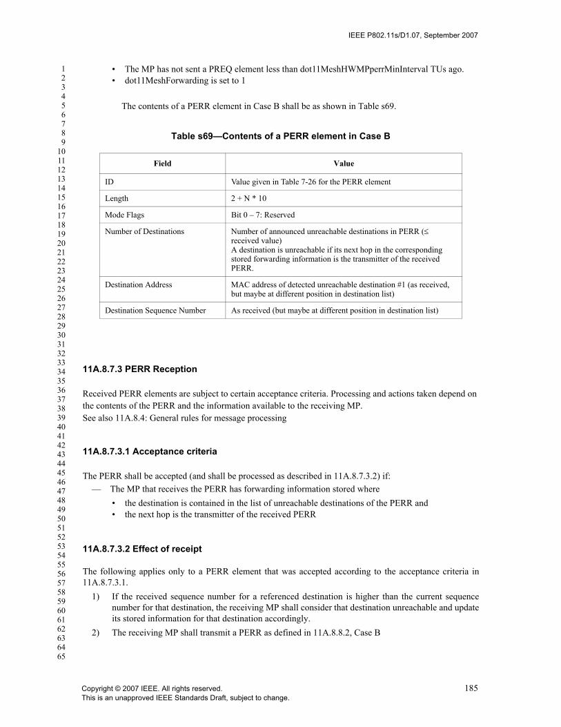
IEEE P802.11s/D1.07, September 2007
123456789
1011121314151617181920212223242526272829303132333435363738394041424344454647484950515253545556575859606162636465
• The MP has not sent a PREQ element less than dot11MeshHWMPperrMinInterval TUs ago. • dot11MeshForwarding is set to 1
The contents of a PERR element in Case B shall be as shown in Table s69.
11A.8.7.3 PERR Reception
Received PERR elements are subject to certain acceptance criteria. Processing and actions taken depend on the contents of the PERR and the information available to the receiving MP.See also 11A.8.4: General rules for message processing
11A.8.7.3.1 Acceptance criteria
The PERR shall be accepted (and shall be processed as described in 11A.8.7.3.2) if:— The MP that receives the PERR has forwarding information stored where
• the destination is contained in the list of unreachable destinations of the PERR and • the next hop is the transmitter of the received PERR
11A.8.7.3.2 Effect of receipt
The following applies only to a PERR element that was accepted according to the acceptance criteria in11A.8.7.3.1.
1) If the received sequence number for a referenced destination is higher than the current sequencenumber for that destination, the receiving MP shall consider that destination unreachable and updateits stored information for that destination accordingly.
2) The receiving MP shall transmit a PERR as defined in 11A.8.8.2, Case B
Table s69—Contents of a PERR element in Case B
Field Value
ID Value given in Table 7-26 for the PERR element
Length 2 + N * 10
Mode Flags Bit 0 – 7: Reserved
Number of Destinations Number of announced unreachable destinations in PERR (≤ received value)A destination is unreachable if its next hop in the corresponding stored forwarding information is the transmitter of the received PERR.
Destination Address MAC address of detected unreachable destination #1 (as received, but maybe at different position in destination list)
Destination Sequence Number As received (but maybe at different position in destination list)
Copyright © 2007 IEEE. All rights reserved. 185This is an unapproved IEEE Standards Draft, subject to change.

IEEE P802.11s/D1.07, September 2007
123456789
1011121314151617181920212223242526272829303132333435363738394041424344454647484950515253545556575859606162636465
11A.8.8 Root Announcement (RANN)
This subclause describes the function, generation and processing of the Root Announcement information ele-ment.
11A.8.8.1 Function
The RANN element, described in 7.3.2.69, is used for announcing the presence of an MP configured as RootMP. RANN elements are sent out periodically by the root MP.
The RANN information element propagates path metric information across the network so that each MP canselect a best metric path to the announced root MP. This mechanism allows bidirectional trees to be built,using a robust procedure based on individually addressed frames initiated by the MPs. This ensures that theroot MP is aware of all MPs in the mesh.
Receiving MPs shall propagate the RANN as described below.
11A.8.8.2 Conditions for generating and sending a RANN
An MP sends out a RANN in the following cases:
Case A: Original transmission
All of the following applies: •The MP is configured as a Root MP •The MP has not sent a PREQ element less than dot11MeshHWMPperrMinInterval TUs ago.•The root MP sent its previous RANN dot11MeshHWMPrannInterval TUs ago
The contents of a RANN element in Case A shall be as shown in Table s70.
Case B: Forwarding
All of the following applies:
Table s70—Contents of a RANN element in Case A
Field Value
ID Value given in Table 7-26 for the RANN element
Length 21
Flags Bit 0: Portal Role (0 = non-portal, 1 = portal)Bit 1 – 7: Reserved
Hop Count 0
Time to Live Maximum number of hops allowed for this element
Originator Address MAC address of the Root MP
Destination Sequence Number Last used DSN + 1
Metric initial metric value (0 for airtime metric)
186 Copyright © 2007 IEEE. All rights reserved.This is an unapproved IEEE Standards Draft, subject to change.

IEEE P802.11s/D1.07, September 2007
123456789
1011121314151617181920212223242526272829303132333435363738394041424344454647484950515253545556575859606162636465
•the MP has valid forwarding information to a root MP•The root MP sent its previous RANN dot11MeshHWMPrannInterval TUs ago •dot11MeshForwarding is set to 1
The contents of a RANN element in Case B shall be as shown in Table s71.
11A.8.8.3 RANN Reception
Received RANN elements are subject to certain acceptance criteria. Processing and actions taken depend on the content of the RANN and the forwarding information maintained by the receiving MP.
See also 11A.8.4: General rules for message processing
11A.8.8.3.1 Acceptance criteria
The RANN element shall not be accepted (and shall not be processed as described in 11A.8.8.3.2) if any of the following is true:
— The DSN < previous DSN from this originator
— (DSN = previous DSN) AND (updated path metric is worse than previous path metric)
11A.8.8.3.2 Effect of receipt
The following applies only to a RANN element that was accepted according to the acceptance criteria in 11A.8.8.3.1.
1) The receiving MP may initiate a PREQ/PREP exchange with the root MP to set up or update a path to the root MP. See PREQ, when generated, case C.
2) The receiving MP shall record the Originator Address, together with the DSN, hopcount, metric.
The receiving MP shall transmit a RANN as defined in 11A.8.8.2, Case B.
Table s71—Contents of a RANN element in Case B
Field Value
ID Value given in Table 7-26 for the RANN ele-ment
Length As received
Flags As received
Hop Count As received + 1
TTL As received – 1
Originator Address As received
Destination Sequence Number As received
Metric As received own link metric toward the transmitting MP
⊕
Copyright © 2007 IEEE. All rights reserved. 187This is an unapproved IEEE Standards Draft, subject to change.
IEEE P802.11s/D1.07, September 2007
123456789
1011121314151617181920212223242526272829303132333435363738394041424344454647484950515253545556575859606162636465
11A.8.9 Considerations for support of STAs without mesh functionality
The verification of disjunct MAC addresses between a non-AP STA without mesh functionality and MPsduring authentication/association of the non-AP STA (11.3.3) may be done by issuing a PREQ for the MACaddress of the non-AP STA by the AP with mesh functionality. The destination only flag of the PREQ shallbe set to 1.
The MAC address of the non-AP STA does already exist in the mesh network if the AP with mesh function-ality receives a PREP for the MAC address of the non-AP STA and it can be derived from the PREP that therequested MAC address is originated from an MP. (The AE flag of the PREP is set to 0, see clause 7.3.2.71).
11A.8.10 HWMP parameters
See T.2 for recommended parameter values.
11A.9 Null path selection protocol
When the active protocol of a mesh is set to Null (see Table s5), MPs do not participate in a multi-hop pathselection protocol. In this case, an MP may exchange management and data frames with any peer MP towhich it has established a mesh link (and completed an MSA 4-way handshake if required) but it need notforward frames to other MPs that are multiple hops away.
11A.10 Intra-mesh congestion control
Intra-Mesh congestion control is based on three main mechanisms: Local congestion monitoring andcongestion detection, congestion control signaling, and local rate control.
While MPs may support multiple congestion control protocols, there is only one congestion control protocolactive in a particular mesh network at a time, signalled in the Congestion Control Mode Identifier field ofthe Mesh Configuration element. The default congestion control protocol specifies congestion controlsignalling. Specific algorithms for local congestion monitoring and congestion detection are beyond thescope of the default congestion control protocol. Similarly, local rate control algorithms are beyond thescope of the default congestion control protocol.
Note: This standard defines a congestion control framework by specifying the congestion control signalling as a defaultprotocol while allowing for inclusion of more advanced or alternative congestion control schemes through the Conges-tion Control Mode Identifier in the Mesh Configuration element.
11A.10.1 Default Congestion Control Protocol
The default congestion control protocol defined in this standard does not specify the exact conditions thatwould trigger congestion control signaling; congestion control signaling is triggered after congestion isdetected at an MP through local congestion monitoring (details of which are beyond the scope of thisstandard).
The default congestion control protocol defines congestion control signalling which consists of a CongestionControl Notification frame. An MP that detects congestion may transmit a Congestion Control Notificationframe. The frame contains the Congestion Notification Element, which specifies the expected duration ofthe congestion per AC as estimated by the congested MP. Other information elements may be included inthe Congestion Control Notification frame.
188 Copyright © 2007 IEEE. All rights reserved.This is an unapproved IEEE Standards Draft, subject to change.

IEEE P802.11s/D1.07, September 2007
123456789
1011121314151617181920212223242526272829303132333435363738394041424344454647484950515253545556575859606162636465
Note: An MP which receives a Congestion Control Notification frame may choose to adjust its frame rate to the senderof the Congestion Control Notification frame in the identified congested AC(s) for the duration specified in the Conges-tion Notification element. Reduction of frame rate to a congested MP avoids waste of the mesh resources for transmis-sion of packets which with high probability will not be handled/forwarded by the congested MP.
11A.11 Mesh beaconing and synchronization
11A.11.1 Synchronization
Synchronization and beacon generation services in a mesh are based upon the procedures defined in 11.1 forInfrastructure and IBSS modes of operation.
It is optional for an MP to support synchronization. An MP supporting synchronization may choose to beeither synchronizing or non-synchronizing based on either its own requirements or the requirements of itspeer MPs. MP’s synchronization behavior is communicated through the “synchronization configurationfield” within the Mesh Configuration element. The synchronizing behaviour for the two classes is defined asfollows.
11A.11.2 Non-synchronizing MPs
A non-synchronizing MP is an MP that maintains an independent TSF timer and may not update the value ofits TSF timer based on time stamps and offsets received in Beacon frames or Probe Response frames fromother MPs. A non-synchronizing MP may start its TSF timer independently of other MPs. The“Synchronizing with peer MP” bit in the “Synchronization Configuration” field of the Mesh Configurationelement, when set to 0, indicates that an MP is currently a non-synchronizing MP. An MP that supportssynchronization may elect to be a non-synchronizing MP if it is communicating with peers that are notrequesting synchronization.
11A.11.2.1 Synchronizing MPs (Optional)
A synchronizing MP is an MP that updates its TSF timer based on the time stamps and offsets (if any)received in Beacon frames and Probe Response frames from other synchronizing MPs. The “Synchronizingwith peer MP” bit in the “Synchronization Configuration” field of the Mesh Configuration element, whenset to 1, indicates that the MP is currently a synchronizing MP.
Synchronizing MPs should attempt to maintain a common TSF time called the Mesh TSF time. An MPmaintains the mesh TSF in terms of its TSF timer and its self TBTT offset such that the sum of the self TSFtimer and the self TBTT offset equals the mesh TSF time. A synchronizing MP shall include the beacontiming element in all Beacon frames and Probe Response frames to advertise its self offset value relative tothe Mesh TSF time.
Synchronizing MPs translate the received time stamps and offsets (if any) from Beacon frames and ProbeResponse frames from other synchronizing MPs to their own timer base, and update their timer as describedas follows:
Translated time stamp = Received time stamp + Received offset (if any) – Receiver’s offset (if any);
A synchronizing MP adopts the translated time stamp as its own if it is later than the timer value of self asdescribed for IBSS mode of synchronization in 11.1.1.2.
Synchronizing MPs may optionally choose to update their offsets instead of their timers. The offset updateprocess in this case is as below.
Copyright © 2007 IEEE. All rights reserved. 189This is an unapproved IEEE Standards Draft, subject to change.

IEEE P802.11s/D1.07, September 2007
123456789
1011121314151617181920212223242526272829303132333435363738394041424344454647484950515253545556575859606162636465
If (received time stamp + received offset) > (self time + self offset)
New self offset value = received time stamp + received offset – self time.
The “Received offset” above is the “self offset” in the received Beacon Timing information element fromthe neighbor MP, and the “Receiver’s offset” is the receiving MP’s own self offset.
11A.11.2.2 Interaction between synchronizing and non-synchronizing MPs
In case the MP requests synchronization from its peer, the MP sets the “Requests Synchronization fromPeer” subfield in the Mesh Configuration element during peer link establishment. However, an MP shouldrequest synchronization from a peer MP only if the peer MP supports synchronization (“SupportingSynchronization” subfield of the Mesh Configuration element is set to 1). If an MP requests synchronizationfrom its peer MPs, it shall be a synchronizing MP at that time. For example, initially, an MP may be in thenon-synchronized state, but it may switch to the synchronized state and vice-versa based on either its ownrequirements or the requirements of peer MPs.
A non-synchronizing MP may change into a synchronizing MP if it is capable of synchronizing, by settingits “Synchronizing with peer MP” bit to 1.
A non-synchronizing MP or an MP that has an established peer link with a non-synchronizing MP shallmaintain information to wake up at the neighboring MP’s Mesh DTIM beacon timing when it is in powersave mode, as described in 11A.12.
11A.11.3 Beaconing
An MP transmits Beacon frames which are specific to mesh. Beacon frames for mesh and BSS aredifferentiated by the capability information field in the beacon frame as specified in 7.3.1.4. If an MP iscollocated with an AP, it generates and transmits beacon frames for mesh and for BSS independently. (Thelogical entity "MP" transmits beacon frames for mesh, and the logical entity "AP" transmits beacon framesfor BSS.) MPs can have independent beacon intervals for mesh beacons and BSS beacons.
An MP may choose to transmit Beacon frames for mesh either as defined in the IBSS mode (11.1.2.2) or asdefined in the infrastructure mode of operation (11.1.2.1).
11A.11.4 Mesh Beacon Collision Avoidance (MBCA) mechanism
Non-synchronizing MPs may optionally adjust their TSF timers and synchronizing MPs may optionallyadjust their offsets to reduce the chances that they will transmit Beacon frames at the same time as one oftheir neighbors or neighbors’ neighbors.
Individual MPs may take steps either prior to, or during peer link establishment, with a mesh to select aTBTT or offset that does not conflict with its mesh neighbors. A non-synchronizing MP may adjust its TSFtimer if it discovers that its TBTT may repeatedly collide with the TBTT of a neighbor. Options an MP hasfor adjusting its TSF include advancing or suspending the TSF for a period of time.
An MP may collect and report information about the TBTT of neighboring MPs using a variety oftechniques. The following describes options to receive such information from neighboring MPs.
a) Information from synchronizing neighborsMPs that are synchronizing collect the beacon timing information of their neighbors and report itthrough the beacon timing information element. This information element may be transmitted inselected Beacon frames, and in action frames responding to requests for such information. Synchro-nizing MPs may choose any frequency of including the beacon timing information in the BeaconTiming information element in their Beacon frames. The beacon timing information may also be
190 Copyright © 2007 IEEE. All rights reserved.This is an unapproved IEEE Standards Draft, subject to change.

IEEE P802.11s/D1.07, September 2007
123456789
1011121314151617181920212223242526272829303132333435363738394041424344454647484950515253545556575859606162636465
requested via action frames (described in 7.4.13.7 and 7.4.13.8), with the response through the bea-con timing information element in action frames. Synchronizing MPs are required to be able torespond to requests for such information using the beacon timing information element.
b) Information from non-synchronizing neighbors
Non-synchronizing MPs may optionally collect and report beacon timing information of their neigh-bors. Since non-synchronizing MPs do not track the mesh TSF, they report beacon time offsets rel-ative to their self TSF. This information either may be periodically transmitted in Beacon frames atwhatever periodicity the MP chooses, or it may be transmitted based on a request response approachthrough action frames. The Beacon Timing information element is used to report this information inBeacon frames as well as in action frames as a response to request action frames. The Self BeaconTiming field in the Beacon Timing information element is set to all zeros in this case.
In addition, beacon reports may be used by MPs to exchange beacon timing information of their neighbors,with the usage as defined in 11.10.8.1.
As an option, MPs may occasionally delay their Beacon frames after their TBTTs for a pseudo-random time.The pseudo-random delay may be chosen so that the transmission time is less likely to collide with otherBeacon frames. This behavior further helps in discovery of neighbors through Beacon frames in case theychoose colliding offsets. The MBCA mechanism may then be used for choosing non-colliding offsets.
11A.12 Power management in a mesh (Optional)
The need for power save in a mesh environment depends on specific scenarios of operation. In certainscenarios where the MPs are all MAPs or only carry backbone traffic, the devices may not be expected to bepower constrained. Specifically MAPs are expected to be awake all the time. However, in scenarios withbattery powered MPs power save can be useful, since this class of devices are expected to be powerconstrained. Power saving in MPs is specified as an optional feature in this standard. The expectation is thatdevices manufactured to operate in specific scenarios choose to implement power save mechanism, whileother devices may be spared the additional overhead of supporting it.
11A.12.1 Overview
Mesh power management is enabled between an MP which supports power save service and an MP whichoperates in power save mode.
An MP which supports power save service is, for convenience, referred to as Power Save Supporting MP,and is capable of signal processing and frame delivery scheme to communicate with MP in power savemode. An MP which operates in power save mode or intends to operate in power save mode is, for conve-nience, referred to as Power Saving MP, and can establish and maintain peer link only with Power Save Sup-porting MPs.
A Power Save supporting MP shall utilize the frame transmission rule defined in this clause, in order todeliver frames to power saving MPs. The Power Save supporting MP shall initialize the power save serviceas described in 11A.12.3, and follow the frame transmission rule described in 11A.12.5. A Power SavingMP shall utilize the frame reception rule defined in this clause, in order to receive frames from Power Savesupporting MPs. The Power Saving MP shall initialize the power save service as described in 11A.12.3,change its Power Management Mode as described in 11A.12.2, and follow the frame reception ruledescribed in 11A.12.4.
MPs shall advertise their capability to support power save in the Power Save Support Enabled bit in theMesh Capability element, included in Beacon and Probe Response frames.
Copyright © 2007 IEEE. All rights reserved. 191This is an unapproved IEEE Standards Draft, subject to change.

IEEE P802.11s/D1.07, September 2007
123456789
1011121314151617181920212223242526272829303132333435363738394041424344454647484950515253545556575859606162636465
An MP which is in Power Save mode or is transitioning to Power Save mode shall set the Power Manage-ment field of the Frame Control field to 1. Such an MP is also called a power saving MP.
In case a neighbor of an MP does not support power save, the MP intending to be in Power Save mode maychoose not to open a peer link with that particular neighbor MP, or it may choose to operate in active modeand open peer link with that neighbor MP.
An MP which intends to operate in Power Save mode may reject a peer link establishment attempt fromanother MP if this MP does not support power save. Similarly, an MP which does not support power savemay reject a peer link establishment attempt from MP whose Power Management field in the Frame Controlfield is set to 1.
The decision of whether to enter Power Save mode or not should be made considering the power versuscommunication constraints. Such a decision can be changed dynamically. An MP may close one or more ofthe established peer links with neighboring MPs, prior to changing its power management mode from activemode to Power Save mode, in order to conserve power consumption.
An MP that has power save capability may or may not have power save supporting capability and an MPwith power save supporting capability may or may not have power save capability. It is possible for an MPto have both power save capability and power save supporting capability.
A power saving MP shall periodically listen for Mesh DTIM beacons of peer MPs, which is determined bythe Mesh DTIM Period field in the Mesh TIM element in Beacon and Probe Response frames transmitted bythese peers. A power saving MP waking to transmit or receive a beacon frame shall stay in the awake statefor a minimum period of Mesh ATIM window as indicated in their Beacon frames, before returning to thedoze state.
A power save supporting MP which has a peer link with an MP in power save mode shall buffer MSDUsdestined for the MP and only transmit them at designated times. MSDUs that are to be transmitted to an MPin power save mode are first announced via the Mesh TIM element in the beacon frame, or by an ATIMframe transmission during the Mesh ATIM window following the Mesh DTIM beacon when neighboringMPs are awake. A power saving MP shall listen for these announcements to determine if it needs to remainin the awake state.
A power save supporting MP which sets up TSPEC with a power saving MP may send traffic to power sav-ing MPs on agreed schedules as negotiated as part of APSD (Automatic Power Save Delivery) TSPECsetup. An MP in Power Save mode which sets up TSPEC with a power save supporting MP shall wakeupaccording to any negotiated schedule as part of TSPEC setup with the power save supporting MP. The MPremains in the awake state until the end of the service period.
11A.12.2 MP Power Management modes
An MP is in one of two different power states:
— Awake: the MP is able to transmit or receive frames and is fully powered.
— Doze: the MP is not able to transmit or receive and consumes very low power.
The manner in which an MP transitions between these two power states shall be determined by the MP’sPower Management mode.
— Active mode: the MP shall be in the Awake state all the time
— Power Save mode: the MP alternates between Awake and Doze states, as determined by the frametransmission and reception rules.
192 Copyright © 2007 IEEE. All rights reserved.This is an unapproved IEEE Standards Draft, subject to change.

IEEE P802.11s/D1.07, September 2007
123456789
1011121314151617181920212223242526272829303132333435363738394041424344454647484950515253545556575859606162636465
An MP shall remain in its current Power Management mode until it informs all of its peer MPs of a PowerManagement mode change via successful frame exchanges.
An MP may change its Power Management mode from Active mode to Power Save mode only when the fol-lowing conditions are fulfilled:
a) All of its peer MPs are power save supporting MPs, and set the Power Save Support Enabled bit inthe Mesh Capability element in beacon or probe response frame to 1.
b) The MP has informed all of its peer MPs that it is changing Power Management mode to PowerSave mode. The Power Management mode change is informed through successful frame exchangesinitiated by the MP. To notify that it is changing to Power Save mode, the MP shall set Power Man-agement bit in the Frame Control field of the frame to 1.
When an MP intends to operate in Power Save mode, it shall send a Null-Data frame with the Power Man-agement bit in its Frame Control field set to 1, to all of its peer MPs. If a peer MP is in Power Save mode,this frame shall be transmitted during the Mesh ATIM window following the mesh DTIM beacon of the peerMP.
After transmitting the Null-Data frame in unicast manner, the MP shall stay in awake state until it completessuccessful frame exchange with all of its peer MPs. Once the MP starts sending this frame, it shall completethe frame exchanges with all of its peer MPs.
Once the MP assures that all the peer MPs recognize its Power Management mode as Power Save mode, itmay transition to Power Save mode.
When the MP is in Power Save mode, the MP shall set the Power Management bit of the Frame Control fieldin all transmitted frames to 1 in order to notify its Power Management mode.
An MP changing its Power Management mode from Power Save mode to Active mode shall inform all of itspeer MPs of the change by sending a Null-Data frame with the Power Management bit of its Frame Controlfield set to 0. Once the MP starts sending this frame, it shall stay in awake state all the time, and shall com-plete the frame exchanges with all of its peer MPs.
If the peer MP is a power saving MP, this frame shall be transmitted during the Mesh ATIM window fol-lowing the mesh DTIM beacon of the peer MP.
The algorithm to trigger the change of power management mode is beyond the scope of the standard.
11A.12.3 Initialization of Power Management within a mesh
All the Power saving MP or MP which intends to operate in Power Save mode shall include Mesh ATIMparameter element in beacon and probe response frames, in order to announce the presence of the MeshATIM window and its Mesh ATIM window parameter to its neighbor MPs. The Mesh ATIM Window isdefined as a specific period of time, defined by the value of the Mesh ATIM Window field in the MeshATIM parameter element.
The start of the Mesh ATIM window is measured from TBTT.
Power save supporting MP shall include Mesh TIM element in beacon and probe response frames in order toannounce its Mesh DTIM count to its neighbors, even if it does not maintain peer link with power savingMP currently.
Copyright © 2007 IEEE. All rights reserved. 193This is an unapproved IEEE Standards Draft, subject to change.

IEEE P802.11s/D1.07, September 2007
123456789
1011121314151617181920212223242526272829303132333435363738394041424344454647484950515253545556575859606162636465
Two different Mesh TIM types are distinguished: Mesh TIM and Mesh DTIM. After a Mesh DTIM, thepower save supporting MP shall send out the buffered broadcast/multicast MSDUs using normal frametransmission rules, before transmitting any unicast frames.
Every Mesh DTIMPeriod, a Mesh TIM of type Mesh DTIM is transmitted within a beacon, rather than anordinary Mesh TIM. The power save supporting MP expects that its peer MPs in Power Save mode wake upper TBTT when the beacon with Mesh DTIM is transmitted. The beacon frame with Mesh DTIM is referredto as mesh DTIM beacon.
Synchronizing MP may not transmit beacon frame regularly, based on the rules described in the beaconingsubclause.
The power management initialization procedure depends on which synchronization mode the MP is operat-ing.
11A.12.3.1 Initialization of Power Management of non-sync MP
A non-synchronizing MP that creates or joins a mesh shall set the Mesh ATIM window, beacon interval,Mesh DTIM interval, and power management mode. These parameters shall be advertised in its Beaconframes regularly.
Non-synchronizing MPs may utilize the independent parameters such as Mesh ATIM window, Mesh DTIMinterval, regardless of these parameters utilized by peer MPs.
A power save supporting non-synchronizing MP assigns AID to every peer MP through the peer link estab-lishment procedure. AID 0 is reserved to indicate the presence of buffered MSDUs with a group addresssuch as broadcast and multicast. This AID is used so that the MP identifies those peer MPs for which it isprepared to deliver buffered MSDUs by setting bits in the Mesh TIM’s partial virtual bitmap that correspondto the appropriate AIDs. MP shall assign AID value uniquely to each of the peer MPs. In case both MPs arepower save supporting MP in establishing a peer relationship, both MPs assign AID each other, unidirec-tionally.
11A.12.3.2 Initialization of Power Management of sync MP
Synchronizing MPs shall utilize the same parameters such as ATIM window, Mesh DTIM interval, amongall the synchronizing peer MPs.
A synchronizing MP that creates a mesh or joins a mesh where all the neighbor MPs are non-synchronizingMPs shall set the Mesh ATIM window, beacon interval, Mesh DTIM interval, and power managementmode. These parameters are advertised in its Beacon frames.
A synchronizing MP that joins a mesh where one or more neighbor MPs are synchronizing MPs shall updateits Mesh ATIM window and Mesh DTIM interval according to the values of received Beacon frames fromthe synchronizing MP and set beacon interval and power management mode. These values are advertised inits Beacon frames.
11A.12.4 Receive operation for MPs in Power Save mode
A power saving MP shall enter awake state prior to every TBTT that matches the mesh DTIM beacon timingof its own and of its neighbor MPs with which it maintains a peer relationship. A Power saving MP shallalso enter awake state at the TBTT when the MP is scheduled to transmit beacon frame.
194 Copyright © 2007 IEEE. All rights reserved.This is an unapproved IEEE Standards Draft, subject to change.

IEEE P802.11s/D1.07, September 2007
123456789
1011121314151617181920212223242526272829303132333435363738394041424344454647484950515253545556575859606162636465
After the Mesh DTIM beacon reception or the beacon transmission, the MP in PS mode may return to thedoze state if any of the neighbor MPs did not make any announcement that the neighbor MP has a frame totransmit to the MP in PS mode, as described later in this subclause.
If an MP enters awake state in order to receive Mesh DTIM beacon and receives broadcast/multicastMSDUs, it shall remain awake until the More Data field of the broadcast/multicast MSDUs indicates thereare no further buffered broadcast/multicast MSDUs or until a Mesh TIM is received indicating there are nomore buffered broadcast/multicast MSDUs.
A power saving MP may transition to awake state if it has traffic to transmit at any given point of time. If anMP transmits beacon frame containing Mesh TIM element indicating the buffered traffic existence, it shallstay awake at least until the next TBTT. If an MP transmits ATIM frame or other frames during the MeshATIM window in order to waken its peer MP, it shall stay awake at least until the next TBTT.
11A.12.4.1 Receiving frames from non-sync MP
Power saving MPs shall operate as follows to receive an MSDU or management frame from the power savesupporting non-synchronizing MP.
a) If a power saving MP receives a Beacon frame with the bit corresponding to its AID is set in theMesh TIM element, the power saving MP shall stay awake after the beacon reception and issue aPS-Poll to retrieve the buffered MSDU or management frame. If the More Data field in the receivedMSDU or management frame indicates that more traffic for the Power Saving MP is buffered, thePower Saving MP shall remain in awake state, and, at its convenience, shall Poll until no moreMSDUs or management frames are buffered for that STA.
b) If a power saving MP transmits beacon frame at a certain TBTT, it shall stay in awake state at leastduring the Mesh ATIM window.If the power saving MP receives an ATIM frame or other frames with the more data bit in the framecontrol field set to 1 during the Mesh ATIM Window following the beacon transmission, it shall stayawake after the Mesh ATIM window expiration, waiting for the announced MSDU(s) or manage-ment frames to be received.
c) If a power saving MP does not receive beacon frame indicating buffered traffic directed to it, anddoes not receive any frame during the Mesh ATIM window following the beacon transmission, itmay return to doze state after the Mesh ATIM window expiration.
d) If an MP operating in Power Save mode received a frame with the more data bit in the frame controlfield cleared from all the peer MPs that announce the buffered traffic, it may return to doze state.
11A.12.4.2 Receiving frames from sync MP
Power saving MPs shall operate as follows to receive an MSDU or management frame from the power savesupporting synchronizing MP.
a) An MP that entered the awake state due to the Mesh DTIM TBTT event and had not sent an ATIM,a broadcast frame, or a multicast frame, and did not receive a unicast or multicast ATIM may returnto the Doze state following the end of the Mesh ATIM window
b) If an MP received an ATIM frame, broadcast frame, or multicast frame, it may return to doze stateafter receiving a frame with the more bit in the control field cleared from all the sources that sent anATIM, broadcast, or multicast frame during the Mesh ATIM window.
c) An MP receiving a broadcast or multicast frame during the Mesh ATIM window with the more databit of its control field cleared may return to the doze state either following the end of the MeshATIM window or after receiving a frame with the more bit in the control field cleared from all otheractive sources, whichever comes later.
Copyright © 2007 IEEE. All rights reserved. 195This is an unapproved IEEE Standards Draft, subject to change.

IEEE P802.11s/D1.07, September 2007
123456789
1011121314151617181920212223242526272829303132333435363738394041424344454647484950515253545556575859606162636465
11A.12.4.3 Receive operation using APSD
A Power Saving MP using APSD shall operate as follows to receive an MSDU or management frame fromthe Power Save Supporting MP which is capable of supporting APSD.
a) If a periodic SP has been set up, the Power Saving MP wakes up at its scheduled start time. (ThePower Saving MP shall wake up early enough to receive transmissions at the scheduled SP.)
b) If the Power Saving MP is initiating an aperiodic SP, the Power Saving MP wakes up and transmitsa trigger frame to the Power Save Supporting MP. When one or more ACs are not delivery-enabled,the Power Saving MP may retrieve MSDUs and MMPDUs belonging to those ACs by sending PS-Poll frames to the Power Save Supporting MP.
c) The Power Saving MP shall remain awake until it receives a QoS data frame addressed to it, with theEOSP subfield in the QoS Control field set to 1.
d) The Power Saving MP may send additional PS-Poll frames if the More Data subfield is set to 1 inreceiving unicast data or management frames that do not belong to any deliver-enabled ACs. ThePower Saving MP may send additional trigger frames if the More Data subfield is set to 1 in receiv-ing unicast data or management frames that belong to delivery-enabled ACs.
11A.12.5 Transmit operation for MPs transmitting to MPs in Power Save mode
The Power Save supporting MP which has a peer link with Power Saving MP shall not arbitrarily transmitMSDUs to Power Saving MPs, but shall buffer MSDUs and only transmit them at designated times so thatthe frames are received by Power Saving MPs.
All broadcast and multicast traffic shall be buffered by Power Save supporting MPs that maintains peer rela-tionship with Power Saving MP. These frames are transmitted immediately after the Mesh DTIM beacontransmission.
All unicast frames targeted to Power Saving MPs shall be buffered.
Prior to the transmission of unicast frames that are to be received by a Power Saving MP, Power Save sup-porting MP shall announce the buffered traffic existence. This announcement scheme depends on whichsynchronization mode the Power Save supporting MP is operating.
11A.12.5.1 Operation of power save supporting non-sync MP
Non-synchronizing MPs announce the traffic by transmitting a beacon frame with Mesh TIM element indi-cating the existence of the traffic buffered to the Power Saving MP.
At every beacon interval, the Power Save supporting non-sync MP shall assemble the partial virtual bitmapcontaining the buffer status per destination for peer MPs in the Power Save mode and shall send this out inthe Mesh TIM field of the beacon.
Its peer MP in Power Save mode shall issue the PS-Poll frame upon the reception of such a beacon frame toretrieve the frame, and buffered frames at the power save supporting MP are transmitted upon the receptionof PS-poll frames.
The More Data field of the transmitting Data frame shall be set to indicate the presence of further bufferedMSDUs or management frames for the polling power saving MP.
Power Save supporting non-sync MPs may transmit frame to a power saving MP during the Mesh ATIMwindow in order to signal them to remain awake and wait for further traffic, if it does not establish peer linkwith the power saving MP. After the positive acknowledgement upon the frame transmission during theMesh ATIM window, MP may further transmit buffered frame to the Power Saving MP.
196 Copyright © 2007 IEEE. All rights reserved.This is an unapproved IEEE Standards Draft, subject to change.

IEEE P802.11s/D1.07, September 2007
123456789
1011121314151617181920212223242526272829303132333435363738394041424344454647484950515253545556575859606162636465
11A.12.5.2 Operation of power save supporting sync MP
Synchronizing MPs announce the traffic by transmitting ATIM frames or null frame to an MP in PowerSave mode during the Mesh ATIM window, in order to signal them to remain awake and wait for furthertraffic. Synchronizing MP shall follow the Frame transmission rules as following.
a) The only types of frames MPs may transmit during the Mesh ATIM window of synchronizing MPsare ACK, CTS, RTS, ATIM, Beacon, broadcast or multicast MPDU and Null Data frames. An MPmay transmit any type of frames during the Mesh ATIM window of non-synchronizing MPs.
b) An MP may transmit one short broadcast or multicast MPDU during the Mesh ATIM window if theMAC frame length of the MPDU is less than dot11shortMulticastFrameLengthLimit. If the MP hasmore than one broadcast or multicast frame to transmit, it should set the more data bit of the broad-cast or multicast frame transmitted during the Mesh ATIM window and contend for the channel fol-lowing the end of the Mesh ATIM window to transmit the additional frames.
c) MPs that transmit to MPs in Power Save mode (including broadcast and multicast) shall set theMore data bit in frame control headers to indicate if more frames are to be transmitted for the spe-cific destination.
d) All other aspects of ATIM based transmission are as defined in 11.2.2.4.
11A.12.5.3 Operation of APSD supporting MP
Power Save Supporting MPs that signal their support of APSD shall maintain an APSD and an access policystatus for each ACs of peer MPs which utilize APSD.
If the Power Saving MP has set up to use aperiodic SPs, the Power Save supporting MP shall buffer framesbelonging to delivery-enabled ACs until it has received a trigger frame associated with a trigger-enabled ACfrom the Power Saving MP, which indicates the start of an aperiodic SP. The Power Save supporting MPtransmits frames destined for the Power Saving MP and associated with delivery-enabled ACs during aperi-odic SP.
For traffic that belongs to a flow for which an APSD TSPEC and schedule was setup with another MP, thetransmission is performed according to the agreed schedule.
When the Power Save Supporting MP has transmitted a directed frame to the Power Saving MP with theESOP subfield set to 1 during the SP and receives acknowledgement, the Power Save Supporting MP shallnot transmit any more frames using this mechanism until the next SP. The Power Save Supporting MP shallset the ESOP subfield to 1 to indicate the end of the SP in APSD.
11A.12.6 Power management with APSD
MPs capable of supporting automatic power save delivery (APSD) shall signal this capability through theuse of the APSD subfield in the Capability Information field in Beacon, Probe Response, and Peer Linkmanagement frames. APSD is enabled only at the peer link which both MPs are capable of APSD.
APSD is an additional frame delivery scheme to a basic Power Save mode, and is enabled only at the powersave supporting MP and power saving MP.
In mesh, APSD defines two delivery mechanisms, periodic and aperiodic APSD. The periodic APSD modeis similar to Scheduled APSD. The aperiodic APSD is similar to Unscheduled APSD. The periodic and ape-riodic APSD modes use the same signaling as scheduled and unscheduled APSD.
Copyright © 2007 IEEE. All rights reserved. 197This is an unapproved IEEE Standards Draft, subject to change.

IEEE P802.11s/D1.07, September 2007
123456789
1011121314151617181920212223242526272829303132333435363738394041424344454647484950515253545556575859606162636465
11A.12.6.1 Aperiodic APSD
The power saving MP transmits trigger frame to the Power Save supporting MP in order to trigger aperiodicSP to receive frames from the Power Save Supporting MP.
If there is no unscheduled SP in progress, the unscheduled SP begins when the MP receives a trigger framefrom a peer MP in Power Save mode, which is a QoS data or QoS Null frame associated with an AC theSTA has configured to be trigger-enabled. An aperiodic SP ends after the Power Save supporting MP hasattempted to transmit at least one MSDU or MMPDU associated with a delivery-enabled AC and destinedfor the Power Saving MP, but no more than the number indicated in the Max SP Length field if the field hasa nonzero value.
In order to configure an Power Save Supporting MP to deliver frames during an aperiodic SP, the PowerSaving MP designates one or more of its ACs to be delivery-enabled and one or more of its AC to be trigger-enabled. A Power Saving MP may configure an Power Save Supporting MP to use U-APSD using twomethods. First, a non-AP STA may set individual U-APSD Flag bits in the QoS Info subfield of the QoSCapability element carried in Peer Link management frames.
When a U-APSD Flag bit is set, it indicates that the corresponding AC is both delivery- and trigger-enabled.When all four U-APSD Flag subfields are set to 1 in Peer Link management frames, all the ACs associatedwith the Power Saving MP are trigger- and delivery-enabled during peer link establishment. When all fourU-APSD Flag subfields are set to 0 in Peer Link management frames, none of the ACs associated with thenon-AP STA is trigger- or delivery-enabled during peer link establishment.
11A.12.6.2 Periodic APSD
Periodic APSD can be used for all cases (i.e., both MPs in power save or only one, EDCA or HCCA access).
The ADDTS request is modified to include a Schedule element that describes the requested schedule fromthe MP. The ADDTS response includes the Schedule that can be supported by the other MP and that shouldbe used for this flow. If this schedule is not acceptable to the originating MP it may reattempt the ADDTSrequest with modified schedule or tear down the flow. A non-synchronizing MP shall set the service starttime field of the TSPEC element to the four lower octets of the TSF timer value of the MP that initiates theADDTS request.
For periodic APSD both sides can initiate transactions as long as they are sent within the service intervaldefined. The service interval lasts up to the maximal service duration as defined in the schedule informationelement or if EOSP is declared in frames sent/received for that flow. For a unidirectional flow the originat-ing MP sets the EOSP when it wants to end the service interval. The interval is considered terminated oncethe ACK is received for that frame (if ACK is required). For a bidirectional flow the service period endsonly after both ends of the flow send a frame with EOSP bit set and the matching ACK frames are received.
An MP wishing to reinstate a TS with another MP that is operating in Power Save mode sends a QoS-Nullframe to the MP in Power Save mode during its Mesh ATIM window.
198 Copyright © 2007 IEEE. All rights reserved.This is an unapproved IEEE Standards Draft, subject to change.

IEEE P802.11s/D1.07, September 2007
Copyright © 2007 IEEE. All rights reserved. 199This is an unapproved IEEE Standards Draft, subject to change.
123456789
1011121314151617181920212223242526272829303132333435363738394041424344454647484950515253545556575859606162636465
Annex A (normative) Protocol Implementation Conformance Statement (PICS) proforma
A.4 PICS proforma - IEEE Std 802.11, 2006 Edition
A.4.4 MAC protocol
A.4.4.1 MAC protocol capabilities
Add the following to end of table in A.4.4.1:
Item Protocol capability References Status Support
*PC36 Wireless LAN Mesh 11A O Yes o No o
PC36.1 Mesh key holder security association
11A.4.5 PC34&PC36:M Yes o No o
PC36.2 Mesh key transport protocol 11A.4.6 PC34&PC36:O Yes o No o N/A o
PC36.3 EAP Encapsulation Mecha-nism
11A.4.7 PC34&PC36:O Yes o No o N/A o
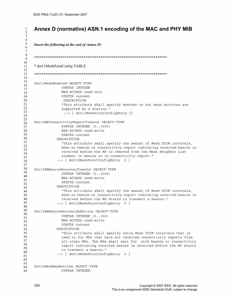
IEEE P802.11s/D1.07, September 2007
123456789
1011121314151617181920212223242526272829303132333435363738394041424344454647484950515253545556575859606162636465
Annex D (normative) ASN.1 encoding of the MAC and PHY MIB
Insert the following at the end of Annex D:
**********************************************************************
* dot11MeshPointConfig TABLE
**********************************************************************
dot11MeshEnabled OBJECT-TYPESYNTAX INTEGERMAX-ACCESS read-onlySTATUS current DESCRIPTION"This attribute shall specify whether or not mesh services are supported by a station." ::= { dot11MeshPointConfigEntry 1}
dot11BBConnectivityReportTimeout OBJECT-TYPESYNTAX INTEGER (0..1000)MAX-ACCESS read-writeSTATUS current
DESCRIPTION"This attribute shall specify the amount of Mesh DTIM intervals, when no beacon or connectivity report indicating received beacon is received before the MP is removed from the Mesh Neighbor List element in beacon or in connectivity report."
::= { dot11MeshPointConfigEntry 2 }
dot11BBBeaconRecoveryTimeOut OBJECT-TYPESYNTAX INTEGER (0..1000)MAX-ACCESS read-writeSTATUS current
DESCRIPTION"This attribute shall specify the amount of Mesh DTIM intervals, when no beacon or connectivity report indicating received beacon is received before the MP starts to transmit a beacon."
::= { dot11MeshPointConfigEntry 3 }
dot11BBBeaconRecoveryAddition OBJECT-TYPE
SYNTAX INTEGER (0..100)MAX-ACCESS read-writeSTATUS current
DESCRIPTION"This attribute shall specify extra Mesh DTIM intervals that is used to for MPs that have not received connectivity reports from all other MPs. The MPs shall wait for with beacon or connectivity report indicating received beacon is received before the MP starts to transmit a beacon."
::= { dot11MeshPointConfigEntry 4 }
dot11MeshMaxRetries OBJECT-TYPESYNTAX INTEGER
200 Copyright © 2007 IEEE. All rights reserved.This is an unapproved IEEE Standards Draft, subject to change.

IEEE P802.11s/D1.07, September 2007
123456789
1011121314151617181920212223242526272829303132333435363738394041424344454647484950515253545556575859606162636465
MAX-ACCESS read-onlySTATUS currentDEFAULT { 0 } DESCRIPTION"This object specifies the maximum number of Peer Link Open retries that can be sent to establish a new link instance in a mesh." ::= { dot11MeshPointConfigEntry 5}
dot11MeshRetryTimeout OBJECT-TYPESYNTAX INTEGERMAX-ACCESS read-onlySTATUS currentDEFAULT { 40 } DESCRIPTION "This object specifies the initial retry timeout, in millisecond units, used by the Peer Link Open message." ::= { dot11MeshPointConfigEntry 6}
dot11MeshConfirmTimeout OBJECT-TYPESYNTAX INTEGERMAX-ACCESS read-onlySTATUS currentDEFAULT { 40 } DESCRIPTION"This object specifies the initial retry timeout, In millisecond units, used by the Peer Link Open message." ::= { dot11MeshPointConfigEntry 7}
dot11MeshHoldingTimeout OBJECT-TYPESYNTAX INTEGERMAX-ACCESS read-onlySTATUS currentDEFAULT { 40 } DESCRIPTION"This object specifies the confirm timeout, in millisecond units, used by the peer link management to close a peer link." ::= { dot11MeshPointConfigEntry 8}
dot11MeshID OBJECT-TYPESYNTAX OCTET STRING (SIZE(0..32))MAX-ACCESS read-writeSTATUS current DESCRIPTION"This attribute reflects the Mesh ID configured in this entity."::= { dot11MeshPointConfigEntry 9}
dot11MeshFirstLevelKeyLifetime OBJECT-TYPESYNTAX Unsigned32 (1..65535)MAX-ACCESS read-writeSTATUS currentDEFVAL ( 10000 ) DESCRIPTION"This attribute shall specify the default lifetime of the PMK-MKD, in minutes when a Session-Timeout attribute is not provided during the EAP authentication."::= { dot11MeshPointConfigEntry 10}
dot11MeshKeyDistributorDomainID OBJECT-TYPESYNTAX OCTET STRING (SIZE(6))
Copyright © 2007 IEEE. All rights reserved. 201This is an unapproved IEEE Standards Draft, subject to change.

IEEE P802.11s/D1.07, September 2007
123456789
1011121314151617181920212223242526272829303132333435363738394041424344454647484950515253545556575859606162636465
MAX-ACCESS read-writeSTATUS current DESCRIPTION"This attribute shall specify the MKD domain identifier of this entity."::= { dot11MeshPointConfigEntry 11}
dot11MeshTTL OBJECT-TYPESYNTAX INTEGER (0..255)MAX-ACCESS read-writeSTATUS current
DESCRIPTION"This attribute shall specify the value of TTL field set at a source MP. The default value for this attribute is 31."
::= { dot11MeshPointConfigEntry 12}
dot11MeshMKDNASID OBJECT-TYPESYNTAX OCTET STRING (SIZE(1..48))MAX-ACCESS read-writeSTATUS current DESCRIPTION"This attribute shall specify the MKD Key Holder identifier of the Authenticator of this entity.NOTE: Backend protocol may allow longer NAS Client identifiers (e.g., RADIUS allows up to 253 octet NAS-Identifier), but when used with Initial MSA Authentication, the maximum length is limited to 48 octets. The same value must be used for the NAS Client identifier and dot11MeshMKDNASID to allow EAP channel binding." ::= { dot11MeshPointConfigEntry 13}
dot11MeshKHHandshakeAttempts OBJECT-TYPESYNTAX INTEGER (1..65535)MAX-ACCESS read-writeSTATUS current DESCRIPTION"The number of times transmission of mesh key holder security handshake messages 1 and 3 will be attempted before indicating failure of the mesh key holder security handshake protocol." ::= { dot11MeshPointConfigEntry 14}
dot11MeshKHHandshakeTimeout OBJECT-TYPESYNTAX INTEGER (1..65535)MAX-ACCESS read-writeSTATUS current DESCRIPTION"The time in milliseconds between transmission attempts of mesh key holder security handshake messages 1 and 3, and between the final transmission attempt and indicating failure of the mesh key holder security handshake protocol." ::= { dot11MeshPointConfigEntry 15}
dot11MeshKeyTransportTimeout OBJECT-TYPESYNTAX INTEGER (1..65535)MAX-ACCESS read-writeSTATUS current DESCRIPTION"The timeout value in milliseconds that a mesh entity waits for a response message in a key transport protocol before indicating failure of the key transport protocol."
202 Copyright © 2007 IEEE. All rights reserved.This is an unapproved IEEE Standards Draft, subject to change.

IEEE P802.11s/D1.07, September 2007
123456789
1011121314151617181920212223242526272829303132333435363738394041424344454647484950515253545556575859606162636465
::= { dot11MeshPointConfigEntry 16}
dot11MeshForwarding OBJECT-TYPESYNTAX INTEGERMAX-ACCESS read-writeSTATUS current DESCRIPTION"This attribute shall specify the ability of a Mesh Point to
forward frames." ::= { dot11MeshPointConfigEntry 17}.
dot11shortMulticastFrameLengthLimit OBJECT-TYPESYNTAX INTEGER (0..2304)MAX-ACCESS read-writeSTATUS current DESCRIPTION"This attribute shall specify the maximum size of one short broadcast or multicast MPDU which may be transmitted during the Mesh ATIM window if the MAC frame length of the MPDU is less than dot11shortMulticastFrameLengthLimit." ::= { dot11MeshPointConfigEntry 18}
**********************************************************************
* End of dot11MeshPointConfig TABLE
*********************************************************************
Copyright © 2007 IEEE. All rights reserved. 203This is an unapproved IEEE Standards Draft, subject to change.

IEEE P802.11s/D1.07, September 2007
123456789
1011121314151617181920212223242526272829303132333435363738394041424344454647484950515253545556575859606162636465
EDITORIAL NOTE—Amendments prior to TGn define Annexes up to Q. TGn defines R and S. Next available is T.
Insert the following new Annex after Annex S:
Annex T Mesh Annex (Informative)
EDITORIAL NOTE—The concept formerly referred to as a lightweight mesh point (LWMP) is enabled by the extensible path selection framework by configuring an MP with the Null path selection protocol. See 11A.9 for more details.
T.1 Overview of Unified Channel Graphs
In its simplest form, a Mesh operates only on one channel. For multi-channel operation, devices needmultiple PHYs. Devices with more than one PHY tune each PHY to a different channel. An overview of theresulting multi-channel operation is provided here.
A Mesh network topology may include MPs with one or more PHY and may utilize one or more channelsfor communication between MPs. Each PHY on an MP operates on one channel at a time, but the channelmay change during the lifetime of the mesh network. The specific channel selection scheme used in a meshnetwork may vary with different topology and application requirements. Figure s66 illustrates three exampleMP channel allocation schemes. (a) illustrates a simple deployment case with single PHY MPs using asingle channel throughout the mesh network. This standard includes a protocol to enable a set of MP PHYsto coalesce to a common channel for communication. (b) and (c) illustrate two advanced channel allocationschemes in which one or more MPs have more than one PHY and more than one channel is used across themesh network. Flexibility is supported to allow implementation of many different possible advancedchannel allocation schemes to meet special application requirements. Different line types indicate differentchannels in Figure s66.
Figure s66—Example channel configurations in a mesh.
(a) (b)
(c)
204 Copyright © 2007 IEEE. All rights reserved.This is an unapproved IEEE Standards Draft, subject to change.

IEEE P802.11s/D1.07, September 2007
123456789
1011121314151617181920212223242526272829303132333435363738394041424344454647484950515253545556575859606162636465
In each of the example topologies, two or more MP PHYs are connected to each other using a commonchannel. A set of MP PHYs that are interconnected to each other via a common wireless mediumcommunication channel is referred to as a unified channel graph (UCG). The same device may belong todifferent UCGs. Multiple UCGs are considered a single mesh to simplify path selection and QoSoptimizations. As illustrated in Figure s67, a simple, single-channel mesh network has only one UCG, whilemore sophisticated topologies may include multiple UCGs. A framework is provided for coordinatedswitching of the channel used within a UCG when it is necessary for channels to change in an operatingmesh network, e.g., due to regulatory DFS requirements. Each UCG in a mesh shares a common channelprecedence value that may be used to coalesce (see 11A.3.2) or switch the channel in the UCG (see11A.3.3).
Figure s67—Example unified channel graphs in a mesh.
UCG #1
UCG #2 UCG #3
UCG #4 UCG #5
Copyright © 2007 IEEE. All rights reserved. 205This is an unapproved IEEE Standards Draft, subject to change.

IEEE P802.11s/D1.07, September 2007
123456789
1011121314151617181920212223242526272829303132333435363738394041424344454647484950515253545556575859606162636465
T.2 Recommended HWMP default values
Parameter Recommended value
Description
dot11MeshHWMPmaxPREQretries 3 The number of action frames containing a PREQ that an MP can send to a particular destination (path target)
dot11MeshHWMPnetDiameterTraversalTime 10 The interval of time (in TUs) that it takes for an HWMP information element to propagate across the Mesh
dot11MeshHWMPpreqMinInterval 100 The minimum interval of time (in TUs) during which an MP can send only one action frame containing a PREQ information element
dot11MeshHWMPperrMinInterval 100 The minimum interval of time (in TUs) during which an MP can send only one action frame containing a PERR information element
dot11MeshHWMPactiveRootTimeout 5000 The time (in TUs) for which MPs receiving a PREQ shall consider the forwardinginformation from the root to be valid
dot11MeshHWMPactivePathTimeout 5000 The time (in TUs) for which MPs receiving a PREQ shall consider the forwarding information to be valid
dot11MeshHWMPpathToRootInterval 5000 The time (in TUs) for which MPs receiving a PREQ shall consider the forwarding information to be valid; must be greater than dot11MeshHWMPrannInterval
dot11MeshHWMPrannInterval 1000 The minimum interval of time (in TUs) during which an MP can send only one action frame containing a RANN information element
206 Copyright © 2007 IEEE. All rights reserved.This is an unapproved IEEE Standards Draft, subject to change.

IEEE P802.11s/D1.07, September 2007
123456789
1011121314151617181920212223242526272829303132333435363738394041424344454647484950515253545556575859606162636465
T.3 Interworking support example and flowcharts
T.3.1 General interworking example topologies
Figure s68 (a) illustrates an example network where two Mesh LANs are bridged with 802.3 LAN segments.In this example, each MPP acts as a bridge, connecting the mesh to another LAN using standard bridgeprotocols (e.g., 802.1D). This configuration effectively creates a single logical layer 2 subnet LANspanning both meshes and two 802.3 LAN segments. Figure s68 (b) illustrates an example network wherethe two Mesh LANs are internetworked with 802.3 LAN segments using layer 3 routing (e.g., IP). In thisexample, the devices where MPP is implemented also includes IP gateway functionality, resulting in anetwork with multiple interconnected subnet LANs.
Two or more meshes may be connected to each other through an entity that implements a Portal and includesone MP for every mesh that it interconnects (see Figure s68 (b)). This may be useful, for example, whendifferent meshes are running different path selection protocols, or are configured differently.
Figure s68—Connecting a Mesh with other LANs via mesh portals. (a) Layer 2 bridging. (b) Layer 3 internetworking.
T.3.2 Operational considerations for interworking
T.3.2.1 Formation and maintenance of the IEEE 802.1D spanning tree
No special action is required to support formation of the IEEE 802.1D spanning tree. Spanning tree controlmessages are typically delivered to bridges in multicast frames. These messages are data frames from thepoint of view of the Mesh.
T.3.2.2 MP mobility
— MP mobility in a bridged network can be within or between physical LANs. Four cases can occur:— Mobility of an MP within the mesh. This kind of mobility is handled through the mesh path selection
mechanisms.— An MP may move from one LAN outside the Mesh to another LAN outside the Mesh. The MPPs
through which the MP can be reached by MPs in the mesh may change. This case occurs in typical
MeshPortal
MeshPortal
MeshPortal
Bridge
802.3 LAN
C
MeshPortal
802.3 LAN
A B
Subnet 1
Subnet 1
Subnet 4
Subnet 3
(a) (b)
Subnet 2
A B
IP Router
MeshPortal
MeshPortal
Copyright © 2007 IEEE. All rights reserved. 207This is an unapproved IEEE Standards Draft, subject to change.

IEEE P802.11s/D1.07, September 2007
123456789
1011121314151617181920212223242526272829303132333435363738394041424344454647484950515253545556575859606162636465
bridged networks and can be handled through bridge learning and timing out of old bridge tableentries.
— An MP may move from inside the Mesh to outside the Mesh. When an on-demand path selection pro-tocol is used, the movement is detected through the path maintenance mechanisms of the protocol,which triggers path repair procedures. When a proactive path selection protocol is used, MP failureand information on the new whereabouts of an MP are disseminated during triggered and periodicpath update rounds.
— An MP may move from outside the Mesh to inside the Mesh. See 11A.6.3 above.
T.4 Power Save parameters selection
The power save operation among synchronizing MPs is controlled by a set of global parameters. The fol-lowing are the global mesh parameters with their default recommended values:
Beacon Period: 100TU Mesh DTIM period: 10Mesh ATIM Window: 10TU
MPs may wish to use other parameters but doing so may effect the power save efficiency and also delay theservice initiation in the mesh.
Non-synchronizing MPs may utilize individual parameters regardless of the parameters used by neighborMPs or peer MPs.
An MP which tries to establish a new peer link with MPs in Power Save mode shall perform passive scan-ning. Since MPs in Power Save mode may transmit Beacons at a low frequency, an MP which tries to estab-lish a new peer link with MPs in Power Save mode should perform passive scanning for a relatively longertime compared to passive scanning in BSS infrastructure mode operation. MPs in Power Save mode whichset a longer Mesh DTIM interval may not be discovered by neighbor MPs due to shorter scan durations.MPs in Power Save mode should set a shorter Mesh DTIM interval, if it intends to establish new peer linkswith MPs with higher probability.
T.5 Design rationale of Abbreviated Handshake protocol
T.5.1 Protocol Overview
The Abbreviate Handshake is intended to secure peer link establishment and key management under theassumption that the two MPs share a PMK. The description here is informative to explain the design ratio-nale of the protocol.
T.5.1.1 Security Goals
The Abbreviated Handshake is designed to satisfy the following major security goals
— Mutual authentication. Achieving mutual authentication in a peer-to-peer environment is challeng-ing. In the client-server model, this always accomplished through some sort of “matching conversa-
208 Copyright © 2007 IEEE. All rights reserved.This is an unapproved IEEE Standards Draft, subject to change.

IEEE P802.11s/D1.07, September 2007
123456789
1011121314151617181920212223242526272829303132333435363738394041424344454647484950515253545556575859606162636465
tions” rule. In the peer-to-peer model, there is no designated initiator or responder; indeed, bothparties might initiate, and an initiator cannot tell it is the “only” initiator. This makes the standardapproaches to “matching conversations” problematic, because the two peers do not and cannot nec-essarily have the same view of message order. The design is based on the conjecture that in the peer-to-peer context mutual authentication should means that both peers have sent and received the sameset of messages—i.e., both have sent and received both an Open and responding Confirm message,both bound to the same instance of the protocol.
— Key secrecy. No party other than the peers authenticated in an Abbreviated Handshake sessionshould learn any information about the resultant session key (in particular, no such third party,watching or interfering with the protocol run, should be able to distinguish the session key from arandom key).
— Consistency property. If the protocol completes successfuly, the two peers should be aware that theyshare the same security-related session state. This means that each parameter should be confirmed aspart of protocol operation. Hugo Krawcyzk introducted the name “consistency property” in hispaper rationalizing the SIGMA design (the basis of IKE). We have found this idea to be anextremely useful heuristic, as various sorts of mis-binding attacks appear possible whenever wedon’t work toward explicitly consistent state at the two peers.
T.5.1.2 Cryptographic Primitives
The following cryptographic algorithms:
a) Random number generator. This is needed to construct challenge values. We will denote this byrand.
b) Message integrity code. This is needed to protect messages against forgeries. The message integritycode tag of a string a under a key K will be denoted by micK(a).
c) Key wrap. The key wrap algorithm is used to distribute the broadcast key of its sender. d) Key derivation function. This “stretches” the PMK into other keys for specific purposes. A key der-
ivation of length bits from key K in the context string a will be denoted by kdfK(a, length).
T.5.1.3 Shared data structures and Secure peer link states
When the protocol completes, we expect the protocol achieves consistency property by synchronizing thefollowing shared data structures:
— Data link addresses, which are used as identifiers. — Random numbers, which are used as challenges and as protocol instance identifiers. — Pairwise Master Key (PMK).
• Each PMK is named by a PMK-ID. • Each PMK has an expiry time.
— The PMK is used to derive three other keys: • the Key Confirmation Key (AKCK), which is the “authentication key” for the abbreviated hand-
shake.• the Key Encryption Key (AKEK), which is the key used to wrap the broadcast key.• the Temporal Key (TK), which is a session key. This key must be ephemeral to make replay
work.• A ciphersuite selector list, identifying the ciphersuites a peer implements and the security policy
it enables. The protocol must negotiate the ciphersuite used with the TK from these lists ofciphersuite selectors.
• GTK, the broadcast key for its source. • A group ciphersuite for the GTK. We do not negotiate the broadcast ciphersuite; the protocol
simply fails if there is no match.
Copyright © 2007 IEEE. All rights reserved. 209This is an unapproved IEEE Standards Draft, subject to change.

IEEE P802.11s/D1.07, September 2007
123456789
1011121314151617181920212223242526272829303132333435363738394041424344454647484950515253545556575859606162636465
• The AKM used by the Abbreviated Handshake itself, for extensibility in the future.
T.5.1.4 Notation
The notation is fairly standard. “a || b” denotes the concatenation of strings a and b. “A B: m” means that Asends message m to B. By [a]K we mean a || macK(a).
T.5.1.5 Summary of the protocol
The rest of T.5 will explain the design rationale of the major functions of Abbreviated Handshake protocol,by incrementally refining the protocol definition. To help readers to refer back to the whole protocol, the fol-lowing uses an example to summarize the execution of Abbreviated Handshake. In this case, MPs A and Binitiate the protocol independently by sending each other an Open message. Once receiving an Open mes-sage, A and B perform negotiation functions of the Abbrevited Handshake. A successful negotiation causesA and B send a Confirm message to notify agreement of the session security states. Each party successfullyestablishes the secure peer link once receiving the Confirm message. The condition of finishing the Abbrevi-ated Handshake is the same as establishing a basic peer link: both parties have successful sent and receivedboth Open and Confirm messages.
A B:Open(A, B, RA ,EA, GroupCiphersuite, CiphersuitesA, AKM, PMKListA,B, AKCK)
B A:Open(B, A, RB, EB, GroupCiphersuite, CiphersuitesB, AKM, PMKListB,A, AKCK)
B A:Confirm(B, A, RB, RA, GroupCiphersuite, AKM, Ciphersuite, PMK-ID, AKCK)
A B:Confirm(A, B, RA, RB, GroupCiphersuite, AKM, Ciphersuite, PMK-ID, AKCK)
The description next in T.5 builds up the thinking about the protocol progressively. It begins with a basicprotocol that is intended to provide “mutual authentication” and an instance identifier. Revisions succes-sively add broadcast key (GTK) distribution, derive session keys, negotiate the ciphersuite consuming thesession key, negotiate which cryptographic algorithms to use in the handshake itself, and finally which keyto use if there is more than one.
T.5.2 Protocol Revision 1: Instance Identifier Agreement
Instance identifier agreement achieves two security goals. First it achieves mutual authentication. Second, itachieves the consistency property for a link instance identifier.
Assume that MPs A and B, but no one else shares the “authentication” key AKCK. For the time being, theAKCK may be treated as a long lived key. Later in T.5.4, this assumption is removed, using key derivation toreplace a long-lived AKCK with an ephemeral key. The message integrity code micAKCK(.) is also fixed forthe following discussion.
The protocol treats the MAC addresses MACA and MACB of the two peer MPs A and B as identifiers for Aand B, respectively. Each party also generates a random number RA and RB. The protocol requires that eachMP commit to its own value for each instance of the protocol it initiates—A must commit to MACA and RA,while B must commit to MACB and RB. In other words, these values are invariant and fixed for each protocolinstance. In particular, if one peer wants to create a new instance of the protocol, it must generate a new ran-dom number. It can associate, however, as many instance created by its peer with this one, in order to defendagainst flooding attacks.
The space of all peer identifiers is lexicographically ordered. The space of random numbers is also orderedlexicographically. The goal of this first version of the protocol is for A and B to agree on a common identi-fier for an instance of the protocol. The instance identifier is given by <min(MACA, MACB), max(MACA,MACB), min(RA, RB), max(RA, RB)>. The 4-tuple uses the min(.,.) and max(.,.) operators in the instance
210 Copyright © 2007 IEEE. All rights reserved.This is an unapproved IEEE Standards Draft, subject to change.

IEEE P802.11s/D1.07, September 2007
123456789
1011121314151617181920212223242526272829303132333435363738394041424344454647484950515253545556575859606162636465
identifier name, because a peer-to-peer does not have a notion of whether A or B should be named first, sothe max and min operators provide the arbitrariness needed to unambiguously identify the instance.
For this first revision of the protocol, let Open(A, B, R, K) represent [MACA || MACB || R]K and Con-firm(A,B,R,S,K) represent [MACA || MACB || R || S]K. At least one of the peers sends an Open message to theother (both could initiate at the same time) to begin a new instance of the protocol:
A uses rand to generate a random RAA B: Open(A,B,RA,AKCK)
On receipt of the first message, the other party does the following:
if RA = RB then [1]B discards Open(A,B,RA,AKCK)
else if MACB is not B’s MAC address then [2]B discards Open(A,B,RA,AKCK)
else if micAKCK(MACA || MACB || RA) is invalid then [3]B discards Open(A,B,RA,AKCK)
elseB instantiates a protocol instance using MACA and RA [4]if B has not sent its own Open(B,A,RB,AKCK) then
B A: Open(B,A,RB,AKCK)
endifB A: Confirm(B,A, RB, RA,AKCK)
endif
A must also execute the same pseudo-code, with the roles of A and reversed. The rationale for each step is asfollows:
— Since the messages used by any peer-to-peer protocol are by necessity symmetric, we need someway to defeat reflection attacks (i.e., the adversary sends A its own messages). The test for equalityin [1] is intended to accomplish this.
— Filtering on MAC address is a simple sanity check, to make sure the receiver to whom the adversarydelivered the message is the intended destination. The test [2] is meant to accomplish this.
— Including a message integrity code in the first message is not standard, but it appears to help estab-lish the consistency property for other parameters added by later protocol revisions below. Thecheck of the message integrity code in [3] limits the adversary to resorting to retries to create forger-ies. This helps defend against flooding attacks. We hypothesize the message integrity code is crucialfor the correctness of a 4 message peer-to-peer protocol.
— If all of the basic sanity checking succeeds, in [4] the receiver instantiates an instance of the protocolbased on the parameters received from its peer. What this means is that B begins with a half-instan-tiated link instance and then pairs each RA received with his own RB to create a fully instantiated linkinstance. In principle this would appear to enable a flooding attack, as the receiver generates a proto-col instance for each valid Open message received from the peer MP. However, we believe this isnecessary, and it is how other protocols, such as TCP and the 802.11 4-Way Handshake, respond toflooding attacks. Its efficacy depends on the peer MP committing to its identifier and random num-ber at the protocol start. Referring back to the peer link management state machine, since each peerMP commits to a MAC address and random number, at most one of these fully instantiated instancescan later advance to the ESTAB state in response to a Confirm message (the one created by the peerholding AKCK). The other instances will time out, enter the HOLDING state, and eventually bepurged. And once it later receives a verified Confirm message from A, B need never accept any fur-
Copyright © 2007 IEEE. All rights reserved. 211This is an unapproved IEEE Standards Draft, subject to change.

IEEE P802.11s/D1.07, September 2007
123456789
1011121314151617181920212223242526272829303132333435363738394041424344454647484950515253545556575859606162636465
ther Open messages for instances of the protocol identified by its own MAC address and randomnumber, except those matching to MACA and RA. Also, since the AKCK is ephemeral in practice, theadversary’s opportunity to effectively replay earlier Open messages with other RA values is limited.
When MP A receives a Confirm message it does the following:
if RB = RA then [5]A discards Confirm(B,A,RB,RA,AKCK)
else if MACA is not A’s MAC address then [6]A discards Confirm(B,A,RB,RA,AKCK)
else if micAKCK(MACB || MACA || RB || RA) is invalid then [7]A discards Confirm(B,A,RB,RA,AKCK)
elseA enters the ESTAB state (A decides the protocol succeeds)
endif
Peer B runs the mirror image pseudo-code, with the roles of A and B reversed, when it receives a Confirmmessage after sending an Open.
Steps [5], [6], and [7] are as before, providing integrity for the Confirm message. The message integrity codebinds the peer identifiers MACA and MACB to the instance identifiers RA and RB. Since by hypothesis RA isunpredictable, the Confirm message could not have been produced before A’s Open message. Since the mes-sage integrity code is valid, it could only be produced by a principal that knows AKCK; since A did not pro-duce this Confirm, and since by assumption B is the only other party that knows AKCK, this Confirm musthave been generated by B in response to A’s Open message.
Note that if RA is not A’s random number, then according to the state machine the Confirm message will notbe delivered to this protocol instance.
We believe that the protocol achieves the consistency property for the instance identifiers. Indeed, the Con-firm message from A to B attests to B that A is using MACA, MACB, RA, and RB for this protocol instance,and similarly the Confirm message from B to A. We further believe that the consistency property plus thefact that A and B sent and received the same set of Open and Confirm messages ought to be counted asmutual authentication.
T.5.3 Protocol Revision 2: Delivering the Group Key
Next we enhance the version of the protocol from T.5.2 to deliver the broadcast key GTK from each MP.The security goal of this enhancement is to achieve the consistency property for the GTKs. This enhance-ment assumes that A and B share a key encryption key AKEK.
The enhancement proceeds by requiring A to wrap its broadcast key GTKA and inserting it into the Openmessage it sends:
Let EA = EKEK(GTKA || MACB || KeyRSCA || GTKExpiryTimeA)Represent Open(A,B,RA,EA),GroupCiphersuiteA, AKCK) as
[MACA || MACB || RA || EA || GroupCiphersuiteA ]AKCK
Wrapping the GTK context MACB with the GTK is intended to allow A to specify the “contract” that GTKAis A’s broadcast key, that B is a member of A’s broadcast group. The KeyRSCA specifies the counter value Auses to send broadcast frame encrypted by GTK. Once B accepts A’s GTK, it should discard any encryptedbroadcast frame with the counter equal to or smaller than the received KeyRSCA.The GTKExpiryTimeA says
212 Copyright © 2007 IEEE. All rights reserved.This is an unapproved IEEE Standards Draft, subject to change.

IEEE P802.11s/D1.07, September 2007
123456789
1011121314151617181920212223242526272829303132333435363738394041424344454647484950515253545556575859606162636465
when the contract expires and received messages constructed using GTKA are no longer valid. The GroupCi-phersuiteA specifies the broadcast cipher suite that A uses with GTKA.
The modified protocol proceeds as in T.5.2, with the addition of a new step [8] to unwrap and validate EAafter receiving the Open message. The the MP choose to unwrap the GTK on reception of the Open message(that is before it sends Confirm message), the following operations are executed:
if RA = RB thenB discards Open(A,B,RA,EA, GroupCiphersuiteA, AKCK)
else if MACB is not B’s MAC address thenB discards Open(A,B,RA,EA, GroupCiphersuiteA, AKCK)
else if micAKCK(MACA || MACB || RA || EA) is invalid thenB discards Open(A,B,RA,EA, GroupCiphersuiteA, AKCK)
else if EA does not unwrap correctly then [8]B discards Open(A,B,RA,EA, GroupCiphersuiteA, AKCK)
else if GroupCiphersuiteA is not the same as set by B’s policy then[9]B discards Open(A,B,RA,EA, GroupCiphersuiteA, AKCK)
B sends a Close message protected by the AKCKB transitions to the HOLDING state (B decides the protocol fails)else
B instantiates a protocol instance using MACA and RA
GroupCiphersuite ← GroupCiphersuiteAif B has not sent its own Open(B,A,RB,AKCK) then
B A: Open(B,A,RB,EB, GroupCiphersuite, AKCK)endifB A: Confirm(B,A,RB, RA, EA, GroupCiphersuite, AKCK)
endif
T.5.3.1 Rantionale of wrapping GTK with the other information
To use this modified pseudo-code, we have to specify what “if EA does not unwrap correctly” means.Unwrapping EA can fail in two ways. First, the unwrap operation may not yield the right IV, in which casethe unwrap fails. Second, the unwrap operation might not yield the “correct” context MACA in which tointerpret the key GTK.
It is not necessary that EA unwraps correctly before B sends the Confirm message to A. B may choose todelay this operation later in the process. However, it is required that the key unwrapping is done correctlybefore the state machine transitions to ESTAB state.
B’s Open message is, of course, symmetric, interchanging the roles of A and B.
[9] points to the policy driven part of the context. Since all parties in the mesh must implement the samebroadcast ciphersuite, the message must be discarded and a Close message sent to reject the request with thisincorrect broadcast ciphersuite.
T.5.3.2 Rationale of sending GTK in Open messages
Sending the GTK in Open message is to achieve consistency property. This operation must not be delayed tothe Confirm message. Indeed, if A sent EA in its Confirm message instead of its Open, then A would not
Copyright © 2007 IEEE. All rights reserved. 213This is an unapproved IEEE Standards Draft, subject to change.

IEEE P802.11s/D1.07, September 2007
123456789
1011121314151617181920212223242526272829303132333435363738394041424344454647484950515253545556575859606162636465
know that B (correctly) received GTKA. Also, if the Open message failed to include a message integritycode, then the adversary could replace EA by a wrapped key transferred in the Open message for a prior pro-tocol instance based on the same AKEK. This could be rectified by having B insert EA (or a hash of it) intothe Confirm responding to A’s Open. However, this affords more opportunities for the protocol to fail at Aand succeed at B, making this choice less attractive. It also represents a significant weakening from the GTKdelivery in the 4-Way and Group Key handshakes, where the GTK delivery is always acknowledged.
Since the received wrapped GTK and the negotiated GroupCiphersuite is sent in the Confirm message, thepseudo-code for processing a received Confirm must change as well:
if RB = RA thenA discards Confirm(B,A,RB,RA, EA, GroupCiphersuite, AKCK)
else if MACA is not A’s MAC address thenA discards Confirm(B,A,RB,RA, EA,GroupCiphersuite,AKCK)
else if micAKCK(MACB || MACA || RB || RA || EA || GroupCiphersuite || PMK-ID) is invalid thenA discards Confirm(B,A,RB,RA, EA, GroupCiphersuite, AKCK)
else if GroupCiphersuite is not the same as sent earlier in an Open message then[10]A discards Confirm(B,A,RB,RA, EA,GroupCiphersuite,AKCK)A sends a Close message protected by the AKCKA transitions to the HOLDING stateelse if EA is not the same as sent earlier in an Open message then[11]A discards Confirm(B,A,RB,RA, EA,GroupCiphersuite,AKCK)A sends a Close message protected by the AKCKA transitions to the HOLDING stateelse
A enters the ESTAB state (the protocol succeeds from A’s perspective)endif
We believe this construction achieves the consistency property for the GTK, because 1) A will not success-fully establish the security association with B unless A can verify GTKB, and vice versa; and 2) A will notsuccessfully establish the security association with B unless A can verify that GTKA has be received by Bcorrectly, and vice versa.
After the security association has been established, either A or B can update their GTK subsequently witheach other. The consistent view of the security association stays that same: A knows that B agrees to useGTKA’ that A sends to B, and vice versa.
This construction is motivated by the design of 4-Way Handshake (8.5.3) and Group Key Handshake (8.5.4)protocols. The GTK belongs to the security association state (see 8.4.1.1), in that failure of confirming thecorrect delivery of GTK causes the AP to de-authenticate the STA (see 8.5.4.3). A mesh does not removestate from security associations, so the delivery both A’s and B’s GTKs should also belong to the securitystate as well. Furthermore, the 4-Way Handshake includes GTK delivery for two purposes. First, this con-struction minimizes a race condition at the receiver regarding the reception of protected broadcast frames—a condition. Second, it is a performance optimization, in that this accomplishes the GTK delivery functionby using 4 instead of 6 messages (4 from the 4-Way Handshake and 2 from the Group Key Handshake).
T.5.4 Protocol Revision 3: Deriving the Session Keys
Next, the protocol is enhanced to use the pairwise master key (PMK), which is the top of the 802.11 keyhierarchy. The assumptions the design makes about the PMK are the following:
— The PMK is only known to A and B.
214 Copyright © 2007 IEEE. All rights reserved.This is an unapproved IEEE Standards Draft, subject to change.

IEEE P802.11s/D1.07, September 2007
123456789
1011121314151617181920212223242526272829303132333435363738394041424344454647484950515253545556575859606162636465
— Ephemeral. The PMK was created recently with expiry time. In other words, the PMK is only validwithin certain period of time.
— PMK has sufficient entropy.
The security goal here is to establish a session key TK known only to the two peers.
The MPs share the PMK and apply a key derivation function kdf:
AKCK || AKEK kdfPMK(0n || min(MACA, MACB) || max(MACA, MACB))
TK kdfPMK(min(RA, RB) || max(RA, RB) || min(MACA, MACB) || max(MACA, MACB))
where n = length RA + length RB in bits, and 0n denotes the string of n zero bits. Here the first assignment ismeant to say that AKCK and AKEK are derived together as one string, with AKCK being the first substring ofAKCK || AKEK and AKEK being the remaining bits. It is standard to assume that the kdf is implemented by apseudo-random function. Under this assumption, this represents a counter-mode construction for a pseudo-random function, because 0n and min(RA, RB) || max(RA, RB) are distinct counter values, applying kdfPMK(.)to arguments constructed from them provides key separation.
Including MACA and MACB is a way to express the “contract” that all of the derived keys are to be used forcommunication only between A and B (or, more technically, between addresses MACA and MACB). T.5.2and T.5.3, have already explained how AKCK and AKEK are used. TK is used to secure data traffic betweenA and B once link establishment protocol succeeds.
Observe that this construction treats AKCK and AKEK as long-lived keys; they can be reused multiple times to form links after PMK has been set. This is of practical significance, because a wireless link can go up and down frequently due to RF disruptions, and it can be relatively expensive to set the PMK.
We believe this construction is acceptable, because this change does not affect the security of GTK wrapping or the freshness of the communication.
— the GTK, not the AKEK, provides the randomization needed to make the keywrap secure— the random values RA and RB, not AKCK, provide the freshness of the message exchange. In particu-
lar, there is no security requirement that AKCK and AKEK differ from one protocol instance to thenext. Including the random numbers RA and RB in the derivation of the TK, however, means that TKwill always be “fresh” after each instance of the protocol.
This construction raises other issues, however. In 802.11s, the PMK is always ephemeral, in the sense that itis created from random inputs whenever an MP joins the mesh. This means that MACA is no longer an effec-tive key identifier for B, and similarly MACB is not a good key identifier for A. A better key identifier is thepeer MAC address plus the shared PMK-ID. It is therefore prudent to add the PMK-ID of the PMK beingused to the Open and Confirm messages exchanged for the receiver to properly identify which key was usedto derive the AKCK, AKEK, and TK.
We believe that our construction meets its security goal of creating a TK known only to A and B if (a) PMKhas sufficient entropy and (b) PMK is itself known only to A and B.
T.5.5 Protocol Revision 4: Negotiating the Session Ciphersuite
It is possible for peers A and B to implement different ciphersuites to protect unicast traffic protected by thesession key TK. However, for communication to be possible, A and B must agree on a common ciphersuiteto use with TK. This section attempts to enhance the protocol version defined in T.5.4 with this new capabil-ity.
Copyright © 2007 IEEE. All rights reserved. 215This is an unapproved IEEE Standards Draft, subject to change.

IEEE P802.11s/D1.07, September 2007
123456789
1011121314151617181920212223242526272829303132333435363738394041424344454647484950515253545556575859606162636465
The security goal is to achieve the consistency property for the instance ciphersuite.
Each peer identifies the ciphersuites it is willing to use with a list of identifiers for each enabled ciphersuite.802.11 calls each ciphersuite identifier a selector. Let us call A’s list of selectors CiphersuitesA, and B’s listCiphersuitesB. We require that each party orders its ciphersuite selectors by preference, from most to leastpreferred. A adds its ciphersuites list to its Open message:
Open(A) = [MACA || MACB || RA || EA) || GroupCiphersuiteA || CiphersuitesA || PMK-ID]{K}
and similarly for B. The receiver pseudo-code for the Open message is modified as follows (assuming EA isunwrapped on receipt of the Open message):
if RA = RB thenB discards Open(A,B,RA,EA, GroupCiphersuiteA,CiphersuitesA,AKCK)
else if MACB is not B’s MAC address thenB discards Open(A,B,RA,EA,CiphersuitesA,AKCK)
else if micAKCK(MACA || MACB || RA || EA || GroupCiphersuiteA || CiphersuitesA || PMK-ID) is invalid then
B discards Open(A,B,RA,EA, GroupCiphersuiteA,CiphersuitesA,AKCK)else if EA does not unwrap correctly then
B discards Open(A,B,RA,EA, GroupCiphersuiteA,CiphersuitesA,AKCK)else if GroupCiphersuiteA is not the same as set by B’s policy then
B discards Open(A,B,RA,EA, GroupCiphersuiteA, CiphersuitesA,AKCK)B sends a Close message protected byAKCKB transitions to the HOLDING state
else if CiphersuitesA and CiphersuitesB have an empty intersection then [12]B discards Open(A,B,RA,EA,GroupCiphersuiteA,CiphersuitesA,AKCK)B sends a Close message protected by AKCK
B transitions to the HOLDING stateelse
B instantiates a protocol instance using MACA and RA
GroupCiphersuite ← GroupCiphersuiteA
if MACA > MACB then [13]
Ciphersuite ← A’s most preferred choice in the overlap set
elseCiphersuite ← B’s most preferred choice in the overlap set
endifif B has not sent its own Open then
B A: Open(B,A,RB,EB, GroupCiphersuite,CiphersuitesB,AKCK)
endifB A: Confirm(B,A,RB, RA, EA,GroupCiphersuite,Ciphersuite,AKCK) [14]
endif
216 Copyright © 2007 IEEE. All rights reserved.This is an unapproved IEEE Standards Draft, subject to change.

IEEE P802.11s/D1.07, September 2007
123456789
1011121314151617181920212223242526272829303132333435363738394041424344454647484950515253545556575859606162636465
The conditional test [12] is intended to check whether A and B share any ciphersuites. If they do not, then itis not possible to form a link, so the Open message is discarded. Otherwise, the peers need some method toselect a ciphersuite from those they share. Any such ciphersuite will do, since both parties believe all ofthose in the overlapping set meet their security requirements. This means we can impose a completely arbi-trary rule to select one. [13] uses the ordering of MAC addresses and the preference of the peer with thelarger MAC address to make this selection, which the above pseudo-code assigns to a variable calledCiphersuite. The receiver inserts this choice into its Confirm message in [14].
Strict adherence to the consistency goal suggests that B’s Confirm message should also convey A’s Cipher-suite list. However, since CiphersuitesA is bound by the Open message integrity code to RA, A is assured thatB received CiphersuitesA instead of some other list in the Open.
Since the selected Ciphersuite is sent in the Confirm message, the pseudo-code for processing a receivedConfirm must change as well:
if RB = RA thenA discards Confirm(B,A,RB,RA,EA, GroupCiphersuite,Ciphersuite,AKCK)
else if MACA is not A’s MAC address thenA discards Confirm(B,A,RB,RA,Ciphersuite,AKCK)
else if micAKCK(MACB || MACA || RB || RA || EA || GroupCiphersuite || Ciphersuite || PMK-ID) is invalid then
A discards Confirm(B,A,RB,RA,EA, GroupCiphersuite,Ciphersuite,AKCK)else if GroupCiphersuite is not the same as sent earlier in an Open message thenA discards Confirm(B,A,RB,RA,EA,GroupCiphersuite,Ciphersuite, AKCK)A sends a Close message protected by the AKCKA transitions to the HOLDING state else if EA is not the same as sent earlier in an Open message thenA discards Confirm(B,A,RB,RA, EA,GroupCiphersuite,AKCK)A sends a Close message protected by the AKCKA transitions to the HOLDING stateelse if Ciphersuite is not in CiphersuitesA sent earlier in an Open message then[15]A discards Confirm(B,A,RB,RA, EA,GroupCiphersuite,Ciphersuite,AKCK)A sends a Close message protected by the AKCKA transitions to the HOLDING stateelse
A enters theESTAB state (the protocol succeeds from A’s perspective)endif
Step [15] checks for failures to conform to the protocol. A can end the protocol instance in this case, becausethe Confirm acknowledges A’s random instance identifier RA, so A knows the Confirm is not a replay fromthe adversary.
We believe this revision accomplishes its security goal of achieving the consistency property for the selectedpairwise ciphersuite, because B will not respond to A with an authenticated Confirm message unless (a) itspolicy enables a ciphersuite that A’s policy also allows in A’s Open message and (b) both parties apply thesame (arbitrary) selection rule to select a ciphersuite from the overlapping set.
Implementation Note: In order to simplify future instances based on the same PMK, A and B can cache theselected ciphersuite and use this to short-circuit the intersection construction by truncating their ciphersuite
Copyright © 2007 IEEE. All rights reserved. 217This is an unapproved IEEE Standards Draft, subject to change.

IEEE P802.11s/D1.07, September 2007
123456789
1011121314151617181920212223242526272829303132333435363738394041424344454647484950515253545556575859606162636465
lists in their Open messages. The utility of this depends on the fact that policy changes are relatively rare—they usually depend on software or hardware upgrades.
T.5.6 Protocol Revision 5: Negotiating the Instance AKM
Real protocols need the extensibility property. Even if the existing protocol is “correct,” progress in comput-ing, cryptography, and fashion will someday render, e.g., AES-128, insecure or otherwise unusable, and dif-ferent cryptographic primitives will be needed to secure the abbreviated handshake itself.
802.11 calls the suite of cryptographic algorithms and protocol used to establish keys an authenticated keymanagement suite, or AKM. It is therefore necessary to be able to negotiate the AKM, which the presentsection attempts to add to the functionality of the protocol of Section 8. This would be trivial in the client-server model, but it is messy in the peer-to-peer case.
The security goal for this latest enhancement is to establish the consistency property for the AKM.
The techniques of Section 8 easily apply to this negotiation, but there is an added complication in that ourproposed protocol structure requires “premature” commitment to an AKM before it is negotiated. Weattempt to circumvent this by abandoning a protocol instance started using the “wrong” AKM and starting anew protocol instance based on the “right” AKM.
The first thing to note is that the key derivation procedure from Section 7 must change, or else we end upusing the same AKCK and AKEK with different AKMs, violating basic key hygiene. We obviate this prob-lem by incorporating the AKM selector into the derived keys:
AKCK || AKEK ← kdfPMK(0n || AKM-ID || min(MACA, MACB) || max(MACA, MACB))
TK ← kdfPMK(min(RA, RB) || max(RA, RB) || AKM-ID || min(MACA, MACB) || max(MACA, MACB))
The next step is to insert the AKM-ID into each of the protocol messages. We also require the list of enabledAKMs in the protocol messages, because each party needs to know whether an alternative can be selected ifthe first doesn’t work. We order the AKMList by the preference of the party sending the message, with themost preferred AKM first and least preferred last:
Open(A) = [MACA || MACB || RA || EA || GroupCiphersuiteA || CiphersuitesA || AKMListA || AKMA || PMK-ID] AKCK
Confirm(A) = [MACA || MACB || RA || RB || EA || GroupCiphersuite || Ciphersuite || AKMA || PMK-ID]AKCK
The messages include the AKM selector explicitly, because otherwise the list would have to play conflictingroles in the Confirm message.
Finally, we need abort the current instance if the two parties cannot agree on an AKM. There are three cases:
Case 1: AKMListA has the same first element with AKMListB
Both parties agree from the outset. The protocol instances execute correctly as specified through Section 8 (but with the key derivation and message formats as modified by this section). All we need to do is add the check that the AKMs selected by each peer already match.
Case 2: AKMListA and AKMListB overlap but have different first elements.
Obviously (or perhaps not so obviously) the message authentication code on the received Open or Confirm message must be verified before this case becomes interesting. Otherwise, the adversary can cause one or both of the peers to misbehave and potentially violate AKM consistency.
218 Copyright © 2007 IEEE. All rights reserved.This is an unapproved IEEE Standards Draft, subject to change.

IEEE P802.11s/D1.07, September 2007
123456789
1011121314151617181920212223242526272829303132333435363738394041424344454647484950515253545556575859606162636465
We need an arbitrary rule to choose the AKM. The arbitrary rule we impose is the same as in Section 8, viz. the most preferred AKM of the device with the larger MAC address wins.
In the following we simply discard Confirm messages that arrive while a peer is in this state, because Confirm messages should never happen until the AKM is resolved.
Subcase 1. MACA > MACB.
Let AKMA be A’s most preferred AKM in the overlap between AKMListA and AKMListB.
If AKMA is the first element of A’s AKMListA, then A discards B’s Open message and wait for a new one whose AKMListB begins with the “correct” AKMA. A executes its current instance of the protocol as specified above. It can accept validated Confirm messages that prescribe AKMA for its use. It must discard other Confirms.
Otherwise A (resp. B) creates a new AKMListA′ (resp. AKMListB′) by truncating AKMListA (resp. AKMListB) to begin with AKMA. A (resp. B) then creates a new instance of the protocol based on AKMListA′ (resp. AKMListB′) instead of AKMListA (resp. AKMListB), identified by new random instance identifier RA′ (resp. RB′) using the MLME-PeerLinkActiveOpen primitive (Clause 10.3.40). (“resp.” means respectively)
Subcase 2. MACA < MACB.
Let AKMB be B’s most preferred AKM in the overlap between AKMListA and AKMListB. Same algorithm as in subcase 1, with the roles of A and B reversed..
Case 3: AKMListA has empty intersection with AKMListB
In this case, conversation is impossible. But wait! The message may be a forgery from the adversary instead of the peer. Since we have no way of verifying this case, all we can do is ignore the message and wait for the protocol instance to time out and enter the Holding state.
In order to make above changes take effect, however, the actual key derivation algorithm needs to be consid-ered outside the AKM suite to avoid the inter-dependency problem of the key derivation algorithm and theauthenticated key management suite. The solution is to announce the supported key derivation function else-where in the Open/Confirm/Close messages. In addition, similar to Group Cipher Suite negotiation, a singlekey derivation function needs to be agreed by all nodes in a mesh network. The messages include the KDFselector explicitly. The messages are modified as below:
Open(A) = [MACA || MACB || RA || EA || GroupCiphersuiteA || CiphersuitesA || AKMListA || AKMA || KDFA || PMK-ID] AKCK
Confirm(A) = [MACA || MACB || RA || RB || EA || GroupCiphersuite || Ciphersuite || AKM || KDF || PMK-ID]AKCK
We believe this achieves the consistency goal for the AKM while working around the problem of prematureAKM usage. Verifying the message authentication code (where possible) allows us to at least conclude thatthe Open is no worse than a replay. Starting a new protocol instance whenever a peer’s AKM list does notbegin with the “correct” first element allows the peers to achieve consistency of the AKM within a new pro-tocol instance while abandoning the old.
Copyright © 2007 IEEE. All rights reserved. 219This is an unapproved IEEE Standards Draft, subject to change.
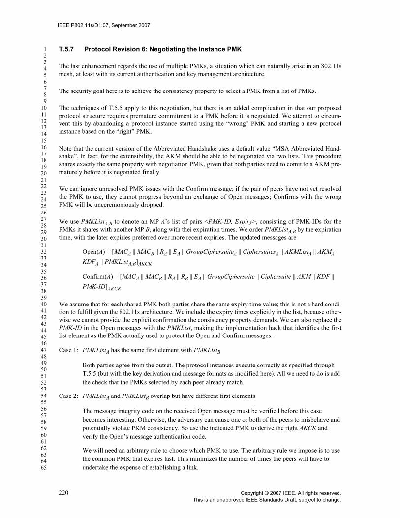
IEEE P802.11s/D1.07, September 2007
123456789
1011121314151617181920212223242526272829303132333435363738394041424344454647484950515253545556575859606162636465
T.5.7 Protocol Revision 6: Negotiating the Instance PMK
The last enhancement regards the use of multiple PMKs, a situation which can naturally arise in an 802.11smesh, at least with its current authentication and key management architecture.
The security goal here is to achieve the consistency property to select a PMK from a list of PMKs.
The techniques of T.5.5 apply to this negotiation, but there is an added complication in that our proposedprotocol structure requires premature commitment to a PMK before it is negotiated. We attempt to circum-vent this by abandoning a protocol instance started using the “wrong” PMK and starting a new protocolinstance based on the “right” PMK.
Note that the current version of the Abbreviated Handshake uses a default value “MSA Abbreviated Hand-shake”. In fact, for the extensibility, the AKM should be able to be negotiated via two lists. This procedureshares exactly the same property with negotiation PMK, given that both parties need to comit to a AKM pre-maturely before it is negotiated finally.
We can ignore unresolved PMK issues with the Confirm message; if the pair of peers have not yet resolvedthe PMK to use, they cannot progress beyond an exchange of Open messages; Confirms with the wrongPMK will be unceremoniously dropped.
We use PMKListA,B to denote an MP A’s list of pairs <PMK-ID, Expiry>, consisting of PMK-IDs for thePMKs it shares with another MP B, along with thei expiration times. We order PMKListA,B by the expirationtime, with the later expiries preferred over more recent expiries. The updated messages are
Open(A) = [MACA || MACB || RA || EA || GroupCiphersuiteA || CiphersuitesA || AKMListA || AKMA || KDFA || PMKListA,B]AKCK
Confirm(A) = [MACA || MACB || RA || RB || EA || GroupCiphersuite || Ciphersuite || AKM || KDF || PMK-ID]AKCK
We assume that for each shared PMK both parties share the same expiry time value; this is not a hard condi-tion to fulfill given the 802.11s architecture. We include the expiry times explicitly in the list, because other-wise we cannot provide the explicit confirmation the consistency property demands. We can also replace thePMK-ID in the Open messages with the PMKList, making the implementation hack that identifies the firstlist element as the PMK actually used to protect the Open and Confirm messages.
Case 1: PMKListA has the same first element with PMKListB
Both parties agree from the outset. The protocol instances execute correctly as specified through T.5.5 (but with the key derivation and message formats as modified here). All we need to do is add the check that the PMKs selected by each peer already match.
Case 2: PMKListA and PMKListB overlap but have different first elements
The message integrity code on the received Open message must be verified before this case becomes interesting. Otherwise, the adversary can cause one or both of the peers to misbehave and potentially violate PKM consistency. So use the indicated PMK to derive the right AKCK and verify the Open’s message authentication code.
We will need an arbitrary rule to choose which PMK to use. The arbitrary rule we impose is to use the common PMK that expires last. This minimizes the number of times the peers will have to undertake the expense of establishing a link.
220 Copyright © 2007 IEEE. All rights reserved.This is an unapproved IEEE Standards Draft, subject to change.

IEEE P802.11s/D1.07, September 2007
123456789
1011121314151617181920212223242526272829303132333435363738394041424344454647484950515253545556575859606162636465
Let us use PMK-ID-latest for this PMK. (Corner case: order PMK-IDs with the same expiry time from smallest to largest, where the PMK-IDs are ordered lexicographically.).
If PMK-ID-latest is first in A’s PMKListA, then A can act just as in Case 1, but must discard messages from B that do not include PMK-ID-latest first. B behaves similarly if PMK-ID-latest is first in its list, although this can be true for at most one of A or B.
If PMK-ID-latest is not the first element of A’s PMKListA, then A creates a new protocol instance (complete with a new instance identifier RA′), using a truncated PMKListA′ that begins with PMK-ID-latest instead of some other key that expires later, and using the MLME-PeerLinkActiveOpen primitive. A should also identify the “correct” AKM to use before initiating the new protocol instance.
If A has sent out an Open message, the old protocol instance enters the HOLDING state without sending a Close message. Otherwise, the old protocol instance should transition to IDLE state directly to close the link instance. On the other hand, the new protocol instance is intended to reduce the problem to case 1.
Case 3: PMKListA has empty intersection with PKMListB
In this case, conversation is impossible. The message may be a forgery from the adversary instead of the peer. Since we have no way of verifying this case, if A has sent out an Open message, the old protocol instance enters the HOLDING state without sending a Close message. Otherwise, the old protocol instance should transition to IDLE state directly to close the link instance. On the other hand, the new protocol instance is intended to reduce the problem to case 1.
T.6 Informative references1
IETF RFC 3561, "Ad hoc On-Demand Distance Vector (AODV) Routing", C. Perkins, E. Belding-Royer, S.Das, July 2003. (status: experimental)
1Internet RFCs are available from the Internet Engineering Task Force at http://www.ietf.org/.
Copyright © 2007 IEEE. All rights reserved. 221This is an unapproved IEEE Standards Draft, subject to change.