ieee p802.3bj d1.3 100 gb/s backplane and copper … p802.3bj d1.3 100 gb/s backplane and copper...
TRANSCRIPT

IEEE P802.3bj D1.3 100 Gb/s Backplane and Copper Cable 4th Task Force review comments
# 50Cl 00 SC 0 P L
Comment Type EThe Working Group maintains a list of preferred spellings on its web pages.Spellings in the draft not in accordance with this list are:6 instances of Gbps instead of Gb/s3 instances of inter-symbol instead of intersymbol3 instances of low frequency instead of low-frequency2 instances of peak to peak instead of peak-to-peak20 instances of steady state instead of steady-state2 instances of signal to noise instead of signal-to-noise5 instances of common mode instead of common-mode (when used as an adjective)3 instances of implementer instead of implementor3 instances of boolean that should be Boolean
SuggestedRemedyChange all instances to be in accordance with Working Group practice.
ACCEPT.
The list in question may be found at:http://www.ieee802.org/3/WG_tools/editorial/requirements/words.html
Comment Status A
Response Status C
bucket
Anslow, Pete Ciena
Response
# 67Cl 00 SC 0 P L
Comment Type ESome hyperlinks to Figures and Tables within the document do not work.
For example:In 91.5.1, the link to Figure 91-2 does not workIn 91.5.2.5, the link to Figure 91-3 does not workIn 91.5.2.8, the link to Figure 91-6 does not workIn 91.5.3.1, the link to Figure 91-8 does not workIn 92.7.7, the link to Table 92-6 does not worketc.
However, some links do work:In 91.5.2.1, the link to Figure 82-10 does work
SuggestedRemedyFix these links, particularly in the new clauses where they will be incorporated into the next revision without modification.
ACCEPT.
Comment Status A
Response Status C
bucket
Anslow, Pete Ciena
Response
# 39Cl 00 SC 0 P L
Comment Type EThe valid editing instructions are "change, delete, insert, and replace" as described on page 21 of the draft.
There are many instances of "add" and three instances of "append" used as editing instructions. These should all be "insert".
Also, many of the instructions that should be or are "insert" do not define where in tables new rows should be placed.
SuggestedRemedyChange "add" and "append" editing instructions to "insert".For all "insert" editing instructions, check that the insertion point is defined.
For example:
In 30.2.5, change: "Append the following into Table 30-7:" to "Insert the following at the end of Table 30-7:"
In 45.2.1.7.4, change: "Add the following rows to the bottom of Table 45-9:" to "Insert the following rows at the bottom of Table 45-9:"
In 45.2.1.100, change "Add rows & changed reserved row in Table 45-73 and add the paragraph to the end of 45.2.1.100:" to "Change the reserved row and insert new rows immediately below it in Table 45-73 and insert the new paragraph at the end of 45.2.1.100 as follows:". Do not show the new text in underline font.
In 73.11.4.3, change "Add item LE8a and change LE14, LE15, and LE17 as shown:" to "Insert item LE8a immediately below item LE8 and change LE14, LE15, and LE17 as shown:"
etc.
ACCEPT.
Comment Status A
Response Status C
bucket
Anslow, Pete Ciena
Response
TYPE: TR/technical required ER/editorial required GR/general required T/technical E/editorial G/general Cl 00SC 0
Page 1 of 681/27/2013 9:02:08
SORT ORDER: Clause, Subclause, page, line COMMENT STATUS: D/dispatched A/accepted R/rejected RESPONSE STATUS: O/open W/written C/closed Z/withdrawn

IEEE P802.3bj D1.3 100 Gb/s Backplane and Copper Cable 4th Task Force review comments
# 66Cl 00 SC 0 P L
Comment Type EAs stated in 1.2.6, "Unless otherwise stated, numerical limits in this standard are to be taken as exact, with the number of significant digits and trailing zeros having no significance."Consequently, trailing zeros should not be shown.
SuggestedRemedyIn 92.8.3.3, page 170, line 52 change "8.0 dB" to "8 dB"In 92.8.3.3, page 170, line 54 change "20.0 dB" to "20 dB"In 92.10, page 180, line 14 change "6.0 dB" to "6 dB"In 94.4.2, page 279, line 41 change "7.0 GHz" to "7 GHz"
ACCEPT.
Comment Status A
Response Status C
bucket
Anslow, Pete Ciena
Response
# 40Cl 30 SC 30.5.1.1.17 P 25 L 29
Comment Type EThe modified text says: "For 1000BASE-PX, 10/40/100GBASE-R, 100GBASE-P PHYs, an array ..." which would be better as:"For 1000BASE-PX, 10/40/100GBASE-R, and 100GBASE-P PHYs, an array ..."
Same issue in 30.5.1.1.18
SuggestedRemedyChange:"For 1000BASE-PX, 10/40/100GBASE-R, 100GBASE-P PHYs, an array ..." to:"For 1000BASE-PX, 10/40/100GBASE-R, and 100GBASE-P PHYs, an array ..."
Make the same change in 30.5.1.1.18
ACCEPT.
Comment Status A
Response Status C
bucket
Anslow, Pete Ciena
Response
# 41Cl 45 SC 45.2.1.100 P 40 L 26
Comment Type EThe paragraph to be added at the end of 45.2.1.100:Register field 1.1501.8 enables testing with the JP03A pattern defined in 94.2.11.1. Register field 1.1501.9 enables testing with the JP03B pattern defined in 94.2.11.2. Register field 1.1501.10 enables testing with the QPRBS13 pattern defined in 94.2.11.3. The assertion of register 1.1501.8, 1.1501.9, 1.1501.10 are mutually exclusive. If more than one bit are asserted the behavior is undefined. The assertion of 1.1501.8, 1.1501.9, and 1501.10 works in conjunction with register field 1.1501.3. If 1.1501.3 is not asserted then 1.1501.8, 1.1501.9, and 101501.10 have no effect.
is written using different terms from the text that is already present in this subclause.Since the existing paragraphs are not being changed, change this text to be in line with what is already there.
Also, "if more than one bit are asserted" should be "if more than one bit is asserted", "operates" seems a better word to use than "works" and "101501.10" should be "1.1501.10".
SuggestedRemedyChange the paragraph to:"Register 1.1501 bit 8 enables testing with the JP03A pattern defined in 94.2.11.1. Register 1.1501 bit 9 enables testing with the JP03B pattern defined in 94.2.11.2. Register 1.1501 bit 10 enables testing with the QPRBS13 pattern defined in 94.2.11.3. The assertion of bits 1.1501.8, 1.1501.9, 1.1501.10 are mutually exclusive. If more than one bit is asserted the behavior is undefined. The assertion of bits 1.1501.8, 1.1501.9, and 1501.10 operates in conjunction with register 1.1501 bit 3. If bit 1.1501.3 is not asserted then bits 1.1501.8, 1.1501.9, and 1.1501.10 have no effect."
ACCEPT.
Comment Status A
Response Status C
bucket
Anslow, Pete Ciena
Response
# 6Cl 45 SC 45.2.1.2 P 30 L 43
Comment Type TPIASA and PEASA are ability registers, so they should be RO property.
SuggestedRemedyChange PIASA and PEASA to RO from R/W.
ACCEPT IN PRINCIPLE.
Also change the first row (unchanged text) to match the base standard.
Comment Status A
Response Status C
bucket
Slavick, Jeff Avago Technologies
Response
TYPE: TR/technical required ER/editorial required GR/general required T/technical E/editorial G/general Cl 45SC 45.2.1.2
Page 2 of 681/27/2013 9:02:12
SORT ORDER: Clause, Subclause, page, line COMMENT STATUS: D/dispatched A/accepted R/rejected RESPONSE STATUS: O/open W/written C/closed Z/withdrawn

IEEE P802.3bj D1.3 100 Gb/s Backplane and Copper Cable 4th Task Force review comments
# 7Cl 45 SC 45.2.1.6.a P 31 L 26
Comment Type TPIASE and PEASE text states that "or not able to stop the ingres direction AUI signalling" which is refering to the ability registers PIASA and PEASA.
SuggestedRemedyChange "is not able to stop the ingress direction AUI signaling" to"is not able to stop the ingress direction AUI signaling (see 1.1.9)"
Make similar change for 45.2.1.6.b
ACCEPT.
Comment Status A
Response Status C
bucket
Slavick, Jeff Avago Technologies
Response
# 70Cl 45 SC 45.2.1.92a P 35 L 46
Comment Type EThe heading row for Table 45-72a contains a blank row above the text i.e. it is two text rows high rather than one.
Same issue for Tables 45-72b, 45-72c, 45-72d, 45-72e, 45-72f, and 45-73
SuggestedRemedyremove the blank text row from the headings of Tables 45-72a, 45-72b, 45-72c, 45-72d, 45-72e, 45-72f, and 45-73
ACCEPT.
Comment Status A
Response Status C
bucket
Anslow, Pete Ciena
Response
# 8Cl 45 SC 45.2.1.92e P 38 L 2
Comment Type TLane mappings for RS-FEC are valid when fec_align_status is set to one, but we don't have any MDIO register that shows the status of fec_align_status
SuggestedRemedyAdd a MDIO register to reflect the state of fec_align_status, maybe as bit 15 of 1.206
ACCEPT IN PRINCIPLE.
Add bit as suggested - similar definition as 3.50.12
Comment Status A
Response Status C
fec_align_status
Slavick, Jeff Avago Technologies
Response
# 279Cl 45 SC 45.2.1.92g P 38 L 47
Comment Type ERTypographical error
SuggestedRemedyReplace "... identical to that described for FEC lane 0 in 45.2.1.92e." by "... identical to that described for FEC lane 0 in 45.2.1.92f."
ACCEPT.
Comment Status A
Response Status C
bucket
Cideciyan, Roy IBM
Response
# 242Cl 45 SC 45.2.1.92j-k P 39 L 22
Comment Type EThe PCS lane number ranges from 0 to 19. Thus a 5-bit (0-31) register should be sufficient. But the "Table 45-72h" assigns a 6-bit register to it. Same comment applies to the other lanes.
SuggestedRemedyChange the register a 5-bit width. Same remedy applies to the other lanes.
ACCEPT.
Note that this error was cut and paste from the lane mapping registers in the base standard. The commenter is invited to submit a maintenance request against the standard to remedy this.
Comment Status A
Response Status C
Register width
Pillai, Velu Broadcom
Response
# 74Cl 45 SC 45.2.3.9 P 41 L 14
Comment Type TIn Register 3.20, the "LPI modes supported" bit has been inserted in the middle of a range of PHY specific bits. It seems better to use bit 15 for this.
SuggestedRemedyChange "LPI modes supported" to bit 15.Change subsequent inserted subclause numbering accordingly.
ACCEPT.
Comment Status A
Response Status C
Bit order
Anslow, Pete Ciena
Response
TYPE: TR/technical required ER/editorial required GR/general required T/technical E/editorial G/general Cl 45SC 45.2.3.9
Page 3 of 681/27/2013 9:02:12
SORT ORDER: Clause, Subclause, page, line COMMENT STATUS: D/dispatched A/accepted R/rejected RESPONSE STATUS: O/open W/written C/closed Z/withdrawn

IEEE P802.3bj D1.3 100 Gb/s Backplane and Copper Cable 4th Task Force review comments
# 73Cl 45 SC 45.2.3.9 P 41 L 19
Comment Type EThe title of Table 45-105 prior to the amendment was just "EEE capability register bit definitions" so "(Register 3.20)" has been added, but is not shown in underline font.
Also, "R/W = Read/Write," has been added to footnote a without underline
SuggestedRemedyShow the addition of "(Register 3.20)" and the addition to footnote a in underline font
ACCEPT IN PRINCIPLE.
Delete "(Register 3.20)" from the table title, fix footnote underlining.
Comment Status A
Response Status C
bucket
Anslow, Pete Ciena
Response
# 42Cl 45 SC 45.2.3.9.e P 42 L 17
Comment Type E"valid for PHYs <40 Gb/s" would be better as "valid for PHYs with rates less than 40 Gb/s"
Similarly, in 45.2.7.13.a, "for PHYs less than 40 Gb/s" would be better as "for PHYs with rates less than 40 Gb/s"
SuggestedRemedyChange:"valid for PHYs <40 Gb/s" to:"valid for PHYs with rates less than 40 Gb/s"
In 45.2.7.13.a, change:"for PHYs less than 40 Gb/s" to:"for PHYs with rates less than 40 Gb/s"
ACCEPT.
Comment Status A
Response Status C
bucket
Anslow, Pete Ciena
Response
# 75Cl 45 SC 45.2.7.13 P 44 L 12
Comment Type TIn Register 7.60, the "LPI modes supported" bit has been inserted as bit 14, which will be in the middle of a range of PHY specific bits when more PHYs are added. It seems better to use bit 0 for this.
Same issue for Register 7.61
SuggestedRemedyChange "LPI modes supported" to bit 0.Change subsequent inserted subclause numbering accordingly.
Make the equivalent change in Register 7.61
ACCEPT IN PRINCIPLE.
The placement of this bit (almost) matches the placement in register 3.20.
Change the bit number to 15. No need for renumbering subclauses.
Same for Register 7.61
Comment Status A
Response Status C
Bit order
Anslow, Pete Ciena
Response
# 86Cl 45 SC 45.2.7.13 P 44 L 12
Comment Type TClause references and next page bit numbers are TBD for bits 7.60.7 to 7.60.14.
SuggestedRemedyAdd clauses references and next page bit numbers for these bits.
ACCEPT IN PRINCIPLE.
All clause references are 73.7.7.1.
Bit numbers are:
7.60.7 - U7, 7.60.8 - U8, etc. . 7.60.14 - U14
Comment Status A
Response Status C
Bit order
Healey, Adam LSI Corporation
Response
TYPE: TR/technical required ER/editorial required GR/general required T/technical E/editorial G/general Cl 45SC 45.2.7.13
Page 4 of 681/27/2013 9:02:12
SORT ORDER: Clause, Subclause, page, line COMMENT STATUS: D/dispatched A/accepted R/rejected RESPONSE STATUS: O/open W/written C/closed Z/withdrawn

IEEE P802.3bj D1.3 100 Gb/s Backplane and Copper Cable 4th Task Force review comments
# 87Cl 45 SC 45.2.7.14 P 46 L 35
Comment Type TClause references and next page bit numbers are TBD for bits 7.61.7 to 7.61.14.
SuggestedRemedyAdd clauses references and next page bit numbers for these bits.
ACCEPT IN PRINCIPLE.
All clause references are 73.7.7.1.
Bit numbers are:
7.61.7 - U7, 7.61.8 - U8, etc. . 7.61.14 - U14
Comment Status A
Response Status C
Bit order
Healey, Adam LSI Corporation
Response
# 9Cl 45 SC 45.2.7.14 P 46 L 35
Comment Type TEEE link partner ability register for LPI modes supported is listed as R/W, should be RO
SuggestedRemedyChange R/W to RO for MDIO register 7.61.14 in table 45-191
ACCEPT.
Comment Status A
Response Status C
bucket
Slavick, Jeff Avago Technologies
Response
# 43Cl 69 SC 69.2.4 P 53 L 9
Comment Type EIn Table 69-1a the heading for Clause 91 is "100GBASE-R RS-FEC" which is not consistent with the term used elsewhere (and in Table 80-2a)
SuggestedRemedyChange the heading to "RS-FEC"
ACCEPT.
Comment Status A
Response Status C
bucket
Anslow, Pete Ciena
Response
# 44Cl 73 SC 73.3 P 54 L 17
Comment Type E"100GBASE-KR4" is split across two lines. Prevent this from happening by replacing the "-" with a non-breaking hyphen (Esc - h)
SuggestedRemedyReplace the "-" in "100GBASE-KR4" with a non-breaking hyphen (Esc - h)
ACCEPT.
Comment Status A
Response Status C
bucket
Anslow, Pete Ciena
Response
# 45Cl 73 SC 73.6.10 P 55 L 7
Comment Type EThe editing instruction is "Replace". This is described on page 21 of the draft as: "Replace is used to make changes in figures or equations by removing the existing figure or equation and replacing it with a new one."Therefore the strikeout and underline fonts are not appropriate and the third paragraph of the subclause would not be shown.
Similar issue with 73.7.2
SuggestedRemedyChange the editing instruction to:"Change 73.6.10 as shown:"
Change the editing instruction for 73.7.2 to:"Change 73.7.2 as shown:"
ACCEPT.
Comment Status A
Response Status C
bucket
Anslow, Pete Ciena
Response
# 49Cl 78 SC 78.2 P 60 L 35
Comment Type EThe editing instruction says:"Change table title and column heading and add rows to Table 78-2 to for 100Gb/s Ethernet:" but the inserted rows include 40G PHYs.
SuggestedRemedyChange the Table 78-2 editing instruction to:"Change table title and column heading and insert rows at the bottom of Table 78-2 as follows:"
ACCEPT.
Comment Status A
Response Status C
bucket
Anslow, Pete Ciena
Response
TYPE: TR/technical required ER/editorial required GR/general required T/technical E/editorial G/general Cl 78SC 78.2
Page 5 of 681/27/2013 9:02:12
SORT ORDER: Clause, Subclause, page, line COMMENT STATUS: D/dispatched A/accepted R/rejected RESPONSE STATUS: O/open W/written C/closed Z/withdrawn

IEEE P802.3bj D1.3 100 Gb/s Backplane and Copper Cable 4th Task Force review comments
# 71Cl 78 SC 78.2 P 61 L 8
Comment Type EThe additional rows in Table 78-2 are formatted differently from the existing rows.
In Table 78-2 of IEEE Std 802.3-2012 numbers above 1000 are shown with a space as a thousands separator. However the new rows do not have this space.
SuggestedRemedyChange "1700" to "1 700" (7 instances) and change "1800" to "1 800" (7 instances) to match the existing table.
ACCEPT.
Comment Status A
Response Status C
bucket
Anslow, Pete Ciena
Response
# 46Cl 78 SC 78.4.2.5 P 64 L 3
Comment Type EThe editing instruction says: "Add the following state diagrams at the end of 78.4.2.5" but there is text to be added as well.
Also, Figure 78-6 is the last figure in Clause 78 so they should be numbered Figures 78-7 and 78-8.
SuggestedRemedyChange the editing instruction to:"Insert the following text and state diagrams at the end of 78.4.2.5"
Change the figure numbers to 78-7 and 78-8
ACCEPT.
Comment Status A
Response Status C
bucket
Anslow, Pete Ciena
Response
# 47Cl 78 SC 78.5 P 67 L 29
Comment Type EInserting the text and figure with separate editing instructions is not necessary and is different from the way this has been done elsewhere in the draft.There is no reference to the new figure in the text.The figure number in the second editing instruction does not match that of the inserted figure.The figure number should be 78-9 because two previous figures have been inserted in 78.4.2.5 (see separate comment about those figure numbers)
SuggestedRemedyRemove the second editing instruction and change the first one to:"Insert the following text and figure at the end of 78.5:"Add a reference to the new figure in the text.Change the figure number to 78-9.
ACCEPT.
Comment Status A
Response Status C
bucket
Anslow, Pete Ciena
Response
# 81Cl 78 SC 78.5 P 67 L 31
Comment Type TThe text "For PHYs with an operating speed of 40 Gb/s and 100 Gb/s (that implement EEE)" would be better if "40 Gb/s and 100 Gb/s" was changed to "40 Gb/s or 100 Gb/s" since it is not required that PHYs do both.
SuggestedRemedyChange "40 Gb/s and 100 Gb/s" to "40 Gb/s or 100 Gb/s"
ACCEPT.
Comment Status A
Response Status C
Bucket
Anslow, Pete Ciena
Response
TYPE: TR/technical required ER/editorial required GR/general required T/technical E/editorial G/general Cl 78SC 78.5
Page 6 of 681/27/2013 9:02:12
SORT ORDER: Clause, Subclause, page, line COMMENT STATUS: D/dispatched A/accepted R/rejected RESPONSE STATUS: O/open W/written C/closed Z/withdrawn

IEEE P802.3bj D1.3 100 Gb/s Backplane and Copper Cable 4th Task Force review comments
# 116Cl 78 SC 78.5 P 67 L 32
Comment Type TGiven that P802.3bm has adopted an EEE objective to support fast wake operation and assuming that fast wake signaling will be modified to be compatible with the OTN mapper, insert a warning that "Deep Sleep" operation must not be enabled for any 40 Gb/s or 100 Gb/s PHY that is transparently mapped over OTN.
SuggestedRemedyInsert the indicated warning.
ACCEPT IN PRINCIPLE.
Although this is not strictly within the scope of this project, a warning can be added as a favor for the other project.
The text and diagram in 78.5 is ill-placed. It should have been added at the end of subclause 78.1.3.3.1. Move the text and diagram and add the following:
Warning: The signaling in deep sleep operation precludes transparent mapping of the link over Optical Transport Networks. Only fast wake operation should be enabled for any link that is intended for transparent OTN mapping.
Comment Status A
Response Status C
OTN
Trowbridge, Steve Alcatel-Lucent
Response
# 72Cl 78 SC 78.5 P 67 L 37
Comment Type EThere should be a non-breaking space (Ctrl Space) between a number and its unit. "mandatory for 40Gb/s and 100Gb/s PHYs" should be "mandatory for 40 Gb/s and 100 Gb/s PHYs"
SuggestedRemedyChange "mandatory for 40Gb/s and 100Gb/s PHYs" to "mandatory for 40 Gb/s and 100 Gb/s PHYs"
ACCEPT.
Comment Status A
Response Status C
bucket
Anslow, Pete Ciena
Response
# 2Cl 78 SC 78.5 P 67 L 40
Comment Type ENote says to add Figure 78-5 at the end of section 78.5 but the figures below is labeled Figure 78-7
SuggestedRemedyChange the note to refer to the proper figure number.
ACCEPT IN PRINCIPLE.
Change to 78-9 per comment #47
Comment Status A
Response Status C
bucket
Slavick, Jeff Avago Technologies
Response
# 115Cl 78 SC 78.5 P 67 L 44
Comment Type TFigure 78-7 Refresh phase is not needed for fast wake. This is something that is needed when the transmitter is turned off during the sleep state as a periodic "hello" to check that the link is up. Since the link remains up with continuous signaling, this is not needed for fast wake. Nor is the "Sleep" signaling needed, since FW signaling asserts LPI. Advance warning is needed if the transmitter is to be turned off, but no advance warning is needed to stop sending data and assert LPI. Note that this is one of several comments aimed to allow use of the same "Fast Wake" operation for optical interfaces.
SuggestedRemedyChange to the necessary four states: Active, FW signaling, Wake, Active
ACCEPT IN PRINCIPLE.
Change the figure to show Active, FW signaling, Wake, Active as suggested, add a note that states:
Note: Fast wake signaling continually indicates LPI in a normally constituted data stream.
Replace Figure 78-7 with the fast wake timing diagram from trowbridge_3bj_01_1113 on slide 5.
Comment Status A
Response Status C
OTN
Trowbridge, Steve Alcatel-Lucent
Response
TYPE: TR/technical required ER/editorial required GR/general required T/technical E/editorial G/general Cl 78SC 78.5
Page 7 of 681/27/2013 9:02:12
SORT ORDER: Clause, Subclause, page, line COMMENT STATUS: D/dispatched A/accepted R/rejected RESPONSE STATUS: O/open W/written C/closed Z/withdrawn

IEEE P802.3bj D1.3 100 Gb/s Backplane and Copper Cable 4th Task Force review comments
# 48Cl 78 SC 78.5 P 68 L 1
Comment Type EThe editing instruction says:"Add rows to Table 78-4 to for 100 Gb/s Ethernet:"The title and heading rows have been changed as well.The inserted rows include 40G PHYs
SuggestedRemedyChange the editing instruction to:"Change table title and column heading and insert rows at the bottom of Table 78-4 as follows:"
ACCEPT.
Comment Status A
Response Status C
bucket
Anslow, Pete Ciena
Response
# 10Cl 78 SC 78.5 P 68 L 12
Comment Type TDefinitions for each of the different case types is needed for Table 78-4.
SuggestedRemedyAdd definitons for the following modes of operation.FAST WAKEDEEP SLEEPSCRAMBLER BYPASS
ACCEPT IN PRINCIPLE.
Change the text style to match the base standard.
Change all instances of FAST WAKE to Case-3; SCRAMBLER BYPASS to Case-2; DEEP SLEEP to Case-1
Add the following text before the table:
Case-1 of the 40GBASE-CR4, 40GBASE-KR4, and 100GBASE-CR10 PHYs applies to PHYs without FEC in deep sleep. Case-2 of these PHYs applies to PHYs with FEC in deep sleep. Case-3 of these PHYs applies to PHYs in fast wake.
Case-1 of the 100GBASE-CR4, 100GBASE-KR4, and 100GBASE-KP4 PHYs applies to PHYs in deep sleep. Case-2 of these PHYs applies to PHYs in fast wake.
Comment Status A
Response Status C
Mode definitions
Slavick, Jeff Avago Technologies
Response
# 76Cl 78 SC 78.5 P 68 L 35
Comment Type TIn Table 78-4, the last inserted row is for "CAUI", but in Table 78-2 the entry was "XLAUI/CAUI"
SuggestedRemedyChange "CAUI" to "XLAUI/CAUI"
ACCEPT.
Comment Status A
Response Status C
bucket
Anslow, Pete Ciena
Response
# 77Cl 78 SC 78.5.2 P 68 L 40
Comment Type TThe title is "40 Gb/s and 100 Gb/s PHY extension using CAUI" but 40G extension uses XLAUI and this is discussed in the subclause text
SuggestedRemedyChange the title to "40 Gb/s and 100 Gb/s PHY extension using XLAUI or CAUI"
ACCEPT.
Comment Status A
Response Status C
bucket
Anslow, Pete Ciena
Response
# 51Cl 79 SC 79.3 P 71 L 6
Comment Type EThe editing instruction is "Add a row and adjust the reserved row of Table 79-1 as shown:", but "add" and "adjust" are not valid editing instructions.
SuggestedRemedyChange editing instruction to:"Change the reserved row of Table 79-1 and insert a new row immediately above it as shown:"
ACCEPT.
Comment Status A
Response Status C
bucket
Anslow, Pete Ciena
Response
TYPE: TR/technical required ER/editorial required GR/general required T/technical E/editorial G/general Cl 79SC 79.3
Page 8 of 681/27/2013 9:02:12
SORT ORDER: Clause, Subclause, page, line COMMENT STATUS: D/dispatched A/accepted R/rejected RESPONSE STATUS: O/open W/written C/closed Z/withdrawn

IEEE P802.3bj D1.3 100 Gb/s Backplane and Copper Cable 4th Task Force review comments
# 52Cl 79 SC 79.3.6 P 71 L 26
Comment Type EIn Figure 79-6a there is "subtype = TBA"It would be helpful to show "TBA" in magenta as per other TBDs
SuggestedRemedyShow "TBA" in magenta
ACCEPT IN PRINCIPLE.
Since the change to 79.3 (Table 79-1) introduced the new subtype as 6 and is not the subject of comment, change TBA to 6
Comment Status A
Response Status C
bucket
Anslow, Pete Ciena
Response
# 53Cl 79 SC 79.3.6 P 71 L 44
Comment Type EFigure 79-6a is inserted after Figure 79-6 which is the last figure in Clause 79. This means that it should be numbered Figure 79-7
SuggestedRemedyChange the figure number to 79-7
ACCEPT.
Comment Status A
Response Status C
bucket
Anslow, Pete Ciena
Response
# 54Cl 79 SC 79.3.a.7 P 72 L 1
Comment Type EThe two subclauses after 79.3.6.1 should be 79.3.6.2 and 79.3.6.1 not 79.3.a.7
SuggestedRemedyFix the numbering of these two subclauses
ACCEPT.
Comment Status A
Response Status C
bucket
Anslow, Pete Ciena
Response
# 56Cl 79 SC 79.4 P 73 L 1
Comment Type EThis is shown as Table 79-7, but it should be Table 79-10
SuggestedRemedyChange the table numbering to be Table 79-10
ACCEPT.
Comment Status A
Response Status C
bucket
Anslow, Pete Ciena
Response
# 55Cl 79 SC 79.4.2 P 72 L 21
Comment Type EThe editing instruction is "Change the second paragraph of 79.4.2 and append rows to Tables 79-9 and 79-10 as shown:" but "append" is not a valid editing instruction.
SuggestedRemedyChange the editing instruction to "Change the second paragraph of 79.4.2 and insert rows at the end of Tables 79-9 and 79-10 as shown:"
ACCEPT.
Comment Status A
Response Status C
bucket
Anslow, Pete Ciena
Response
# 57Cl 79 SC 79.5.3 P 74 L 7
Comment Type EThe editing instruction is "Append a row to major capabilities table in 79.5.3 as shown:" but "append" is not a valid editing instruction.
SuggestedRemedyChange the editing instruction to "Insert a row at the bottom of the major capabilities table in 79.5.3 as shown:"
ACCEPT.
Comment Status A
Response Status C
bucket
Anslow, Pete Ciena
Response
TYPE: TR/technical required ER/editorial required GR/general required T/technical E/editorial G/general Cl 79SC 79.5.3
Page 9 of 681/27/2013 9:02:12
SORT ORDER: Clause, Subclause, page, line COMMENT STATUS: D/dispatched A/accepted R/rejected RESPONSE STATUS: O/open W/written C/closed Z/withdrawn

IEEE P802.3bj D1.3 100 Gb/s Backplane and Copper Cable 4th Task Force review comments
# 103Cl 80 SC 80.3.2 P 80 L 8
Comment Type TRepeating D1.2 comment 407 in different words:Figure 80-3 has nothing to do with Clause 91 FEC (the FEC here has to be Clause 74 FEC), nor with EEE. Therefore nothing in it should change in this project.
SuggestedRemedyDelete:"Change note in Figure 80-3 as shown:NOTE 1-OPTIONAL OR OMITTED DEPENDING CONDITIONAL BASED ON PHY TYPE"
ACCEPT.
Comment Status A
Response Status C
Diagrams
Dawe, Piers IPtronics
Response
# 58Cl 80 SC 80.3.3.4 P 81 L 44
Comment Type EThis says "Without EEE capability (with the deep sleep mode option), the primitive is never invoked ..." which is rather confusingly written.
Same issue in 80.3.3.7
SuggestedRemedyChange to "Without EEE deep sleep mode capability, the primitive is never invoked ..."
Make equivalent change in 80.3.3.7
ACCEPT.
Comment Status A
Response Status C
bucket
Anslow, Pete Ciena
Response
# 210Cl 80 SC 80.4 P 84 L 26
Comment Type TRThe base document says "See 44.3 for the calculation of bit time per meter of fiber or electrical cable."
44.3 includes equation and table which implicitly assume BT = 100 ps (since clause 44 is "Intro to 10 Gb/s"). This is adequate for all 10G PHYs, but not for 40G and 100G PHYs, which are the subject of clause 80.
SuggestedRemedyAdd an instruction to change the sentence"See 44.3 for the calculation of bit time per meter of fiber or electrical cable."to the following text (adding a new equation 80-1):
<start replacement text>Equation (80-1) specifies the calculation of cable delay in nanoseconds per meter of fiber or electrical cable, based upon the parameter n, which represents the ratio of the speed of electromagnetic propagation in the fiber or electrical cable to the speed of light in a vacuum, c = 3x10^8 m/s.
cable delay = 10^9/(n*c)[ns/m] (80-1)
The value of n should be available from the fiber or electrical cable manufacturer, but if no value is known then a conservative delay estimate can be calculated using a default value of n = 0.66, which yields a default cable delay of 5 ns/m.<end replacement text>
There is no need to include a table as in 44-3 - this table is a simple arithmetic result of the formula. There is also no need to have separate equations for delays in BT units, since the conversions to BT are described in the notes of table 80-3.
REJECT.
Such a wide ranging change to the media delay calculation description should be a topic for maintenance.
Comment Status R
Response Status C
Delay
Ran, Adee Intel
Response
TYPE: TR/technical required ER/editorial required GR/general required T/technical E/editorial G/general Cl 80SC 80.4
Page 10 of 681/27/2013 9:02:12
SORT ORDER: Clause, Subclause, page, line COMMENT STATUS: D/dispatched A/accepted R/rejected RESPONSE STATUS: O/open W/written C/closed Z/withdrawn

IEEE P802.3bj D1.3 100 Gb/s Backplane and Copper Cable 4th Task Force review comments
# 204Cl 80 SC 80.4 P 84 L 41
Comment Type TNote for 100GBASE-CR4 PMD says "Does not include delay of cable medium". Copper cable PMDs (40GBASE-CR4 100GBASE-CR4) are the only cases where such exclusion is made.
Why should this delay be left for network planners and administrators to calculate? The cable medium delay per meter is known (Based on table 80-3 it is about 10 ns/m). For 5 meters, this is 50 ns, which dominates over the suggested 100GBASE-CR4 PMD delay.
Accounting for the maximum medium delay will make it easier to calculate total network delay in this case (compare to the backplane PMDs whose medium delay is included; see 84.4).
For optical PMD types, table 80-3 includes 2 m of fiber, which is a precedence for including the delay of a functionally comparable medium.
SuggestedRemedyChange maximum delay for the 100GBASE-CR4 PMD to 16 pause_quanta (and corresponding bit time and ns values).Change the note to "includes 5 m of cable. see 92.4"
ACCEPT IN PRINCIPLE.
Comment #206 addresses 100GBASE-CR4.
For consistency with base standard, in Table 80-3 notes column insert "Includes delay of one direction through backplane medium." in the two backplane PMD rows.
Comment Status A
Response Status C
Delay
Ran, Adee Intel
Response
# 82Cl 80 SC 80.5 P 86 L 8
Comment Type EIn Table 80-4, cross-references for skew allowed at SP0, SP7, RS-FEC transmit, and RS-FEC receive are TBD.
SuggestedRemedyFor SP0 and SP7, refer to 83.5.3.1 and 83.5.3.5 respectively. For RS-FEC transmit and RS-FEC receive, refer to 91.5.2.2 and 91.5.3.1 respectively.
ACCEPT.
Comment Status A
Response Status C
xref
Healey, Adam LSI Corporation
Response
# 83Cl 80 SC 80.5 P 87 L 8
Comment Type EIn Table 80-5, cross-references for skew variation allowed at SP0, SP7, RS-FEC transmit, and RS-FEC receive are TBD.
SuggestedRemedyFor SP0 and SP7, refer to 83.5.3.1 and 83.5.3.5 respectively. For RS-FEC transmit and RS-FEC receive, refer to 91.5.2.2 and 91.5.3.1 respectively.
ACCEPT.
Comment Status A
Response Status C
xref
Healey, Adam LSI Corporation
Response
# 59Cl 81 SC 81.3.1.2 P 90 L 10
Comment Type EThe editing instruction says "Change Table 81-3 as follows:" but only one of the rows of the existing table is shown.Change this to be in line with other table changes in this draft.
Same issue for Table 81-4
SuggestedRemedyChange the editing instruction to "Change the first reserved row of Table 81-3 and insert a new row immediately below it as follows:"Show only one reserved row with "06" in strikethrough and "05" in underline font.
Change the editing instruction and table for Table 81-4 in the same way.
ACCEPT.
Comment Status A
Response Status C
bucket
Anslow, Pete Ciena
Response
# 60Cl 81 SC 81.3.4 P 91 L 47
Comment Type EThe whole subclause 81.3.4 is shown although only one paragraph is changed.
SuggestedRemedyChange the editing instruction to:"Change the third paragraph of 81.3.4 as follows:"and only show the changed paragraph.
ACCEPT.
Comment Status A
Response Status C
bucket
Anslow, Pete Ciena
Response
TYPE: TR/technical required ER/editorial required GR/general required T/technical E/editorial G/general Cl 81SC 81.3.4
Page 11 of 681/27/2013 9:02:12
SORT ORDER: Clause, Subclause, page, line COMMENT STATUS: D/dispatched A/accepted R/rejected RESPONSE STATUS: O/open W/written C/closed Z/withdrawn
IEEE P802.3bj D1.3 100 Gb/s Backplane and Copper Cable 4th Task Force review comments
# 78Cl 81 SC 81.3a.2.1 P 94 L 21
Comment Type TThis says "PMA Ingress AUI Stop Enable (PIASE) bit (1.TBD)"The PIASE bit is 1.7.9
Same issue in 81.3a.3.1
SuggestedRemedyChange "TBD" to "1.7.9" here and in 81.3a.3.1
ACCEPT.
Comment Status A
Response Status C
xref
Anslow, Pete Ciena
Response
# 84Cl 81 SC 81.3a.2.1 P 94 L 21
Comment Type EPIASE is mapped to bit 1.TBD.
SuggestedRemedyReplace 1.TBD with the correct mapping.
ACCEPT IN PRINCIPLE.
Change to 1.7.9 as per comment #11, 12, 78
Comment Status A
Response Status C
xref
Healey, Adam LSI Corporation
Response
# 11Cl 81 SC 81.3a.2.1 P 94 L 21
Comment Type TPIASE bit is TBD, but is now assigned
SuggestedRemedyChange TBD to 1.7.9
ACCEPT.
Comment Status A
Response Status C
xref
Slavick, Jeff Avago Technologies
Response
# 282Cl 81 SC 81.3a.2.1 P 99 L 41
Comment Type TIn the description of the tw_timer it is stated:"A timer that counts, in microseconds, the time since the de-assertion of LPI. The terminal count of the timer is the value of the resolved Tw_sys_tx as defined in 78.2."However Tw_sys_tx minimum values for Fast Wake are much lower than 1 microsecond.
SuggestedRemedyChange the definition of tw_timer to:"A timer that counts, in nanoseconds the time since the de-assertion of LPI. The terminal count of the timer is the value of the resolved Tw_sys_tx as defined in 78.2."
ACCEPT IN PRINCIPLE.
Delete ", in microseconds,"
Comment Status A
Response Status C
Late
Benjamini, Yiftach IBM
Response
# 85Cl 81 SC 81.3a.3.1 P 95 L 43
Comment Type EPIASE is mapped to bit 1.TBD.
SuggestedRemedyReplace 1.TBD with the correct mapping.
ACCEPT IN PRINCIPLE.
Change to 1.7.9 as per comment #11, 12, 78
Comment Status A
Response Status C
xref
Healey, Adam LSI Corporation
Response
# 12Cl 81 SC 81.3a.3.1 P 95 L 44
Comment Type TPIASE bit reference is listed as TBD, but it's been assigned.
SuggestedRemedyChange TBD to 1.7.9
ACCEPT.
Comment Status A
Response Status C
xref
Slavick, Jeff Avago Technologies
Response
TYPE: TR/technical required ER/editorial required GR/general required T/technical E/editorial G/general Cl 81SC 81.3a.3.1
Page 12 of 681/27/2013 9:02:12
SORT ORDER: Clause, Subclause, page, line COMMENT STATUS: D/dispatched A/accepted R/rejected RESPONSE STATUS: O/open W/written C/closed Z/withdrawn

IEEE P802.3bj D1.3 100 Gb/s Backplane and Copper Cable 4th Task Force review comments
# 61Cl 82 SC 82.1.5 P 97 L 52
Comment Type EThe editing instruction for 82.1.5 only changes Figure 82-2 so there is no need to show the text from 82.1.5
SuggestedRemedyRemove the text from 82.1.5.
ACCEPT.
Comment Status A
Response Status C
bucket
Anslow, Pete Ciena
Response
# 235Cl 82 SC 82.2.18.2.3 P 104 L 42
Comment Type TThe note is inconsistent with a similar requirement in 49.2.4.4. A PHY that supports EEE or has the EEE capability, is by definition established in 802.3az a PHY that has the EEE implemented and has negotiated EEE.
78.3 states "During Auto-Negotiation, both link partners indicate their EEE capabilities. EEE is supported only if during Auto-Negotiation both the local device and link partner advertise the EEE capability for the resolved PHY type. If EEE is not supported, all EEE functionality is disabled and the LPI client does not assert LPI. If EEE is supported by both link partners for the negotiated PHY type, then the EEE function can be used independently in either direction."
SuggestedRemedyChange the sentence:"If EEE has not been negotiated or if the PCS does not support EEE, LPIshall not be transmitted and shall be treated as an error if received."to..."If EEE is not supported, LPI shall not be transmitted and shall be treated as an error if received."
ACCEPT IN PRINCIPLE.
Change the sentence:"If EEE has not been negotiated or if the PCS does not support EEE, LPIshall not be transmitted and shall be treated as an error if received."to..."If EEE has not been negotiated, LPI shall not be transmitted and shall be treated as an error if received."
Comment Status A
Response Status C
Brown, Matthew Applied Micro
Response
# 234Cl 82 SC 82.2.18.2.3 P 104 L 42
Comment Type TThe note is inconsistent with a similar note in the T_TYPE definition (page 105, line 21) and for the R_BLOCK_TYPE defintion in Clause 49. A PHY that supports EEE or has the EEE capability, is by definition established in 802.3az a PHY that has the EEE implemented and has negotiated EEE.
78.3 states "During Auto-Negotiation, both link partners indicate their EEE capabilities. EEE is supported only if during Auto-Negotiation both the local device and link partner advertise the EEE capability for the resolved PHY type. If EEE is not supported, all EEE functionality is disabled and the LPI client does not assert LPI. If EEE is supported by both link partners for the negotiated PHY type, then the EEE function can be used independently in either direction."
SuggestedRemedyChange the note to:"A PCS that does not support EEE classifies vectors containing one or more /LI/ control characters as type E."
ACCEPT.
Comment Status A
Response Status C
bucket
Brown, Matthew Applied Micro
Response
# 79Cl 82 SC 82.2.18.3 P 113 L 1
Comment Type TFigures 82-14 and 82-15 have no editing instruction associated with them and no text that refers to them.
SuggestedRemedyAdd an appropriate editing instruction and some text that refers to these two figures.
ACCEPT IN PRINCIPLE.
All of the state diagrams (82-10 through 82-17) are rooted in 82.6. Add editing instructions to change 82-10, 82-11, 82-12, 82-13, 82-14 and 82-15; and to add 82-16 and 82-17.
Comment Status A
Response Status C
bucket
Anslow, Pete Ciena
Response
TYPE: TR/technical required ER/editorial required GR/general required T/technical E/editorial G/general Cl 82SC 82.2.18.3
Page 13 of 681/27/2013 9:02:12
SORT ORDER: Clause, Subclause, page, line COMMENT STATUS: D/dispatched A/accepted R/rejected RESPONSE STATUS: O/open W/written C/closed Z/withdrawn

IEEE P802.3bj D1.3 100 Gb/s Backplane and Copper Cable 4th Task Force review comments
# 63Cl 82 SC 82.2.18.3.1 P 106 L 41
Comment Type E"as shown in figures 82-16 and 82-17." should be "as shown in Figure 82-16 and Figure 82-17."
SuggestedRemedyChange: "as shown in figures 82-16 and 82-17." to: "as shown in Figure 82-16 and Figure 82-17."
ACCEPT.
Comment Status A
Response Status C
bucket
Anslow, Pete Ciena
Response
# 13Cl 82 SC 82.2.18.3.1 P 107 L 15
Comment Type TTimer durations for scrambler bypass are too short. Minimum amount of time spent in scrambler byass is 5 FEC frames. Clause 74 FEC frame is 2112 bits long, so 40G takes 204.8 ns / FEC frame; 100G takes 409.6 ns / FEC frame.
SuggestedRemedyIn Table 82-5aSet Tbyp to be 1.1 to 1.3 us for 40Gbps operationSet Tbyp to be 2.1 to 2.3 us for 100Gbps operation
REJECT.
It is not clear that the extra time is required, the current timing guarantees 3 complete frames with some end/start fragments.
Comment Status R
Response Status C
Timer values
Slavick, Jeff Avago Technologies
Response
# 14Cl 82 SC 82.2.18.3.1 P 107 L 33
Comment Type TThere are two entries for Twr 40Gbps in Table 82-5b, but no 100Gbps entry.
SuggestedRemedyChange the Twr entry which has a max value of 6.5 in Draft 1.3 to be for 100Gbps instead of 40Gbps
ACCEPT.
Comment Status A
Response Status C
bucket
Slavick, Jeff Avago Technologies
Response
# 4Cl 82 SC 82.2.18.3.1 P 107 L 35
Comment Type EWe have nested if then else structure for the time durations of the Twr timer. Shifting the entries to follow that structure makes it easier to understand.
SuggestedRemedyMove the Twr timer when LPI_FW=TRUE to be listed as the first Twr timer in Table 82-5b.
ACCEPT.
Comment Status A
Response Status C
bucket
Slavick, Jeff Avago Technologies
Response
# 15Cl 82 SC 82.2.18.3.1 P 115 L 36
Comment Type TExtra LPI_FW in the FW_TX_WAKE state
SuggestedRemedyRemove the "LPI_FW" from the FW_TX_WAKE state box.
ACCEPT.
Comment Status A
Response Status C
bucket
Slavick, Jeff Avago Technologies
Response
# 5Cl 82 SC 82.2.18.3.1 P 115 L 40
Comment Type EFigure 82-16 extra character in TX_WAKE state for down_count.
SuggestedRemedyChange "idown_count" in TX_WAKE to be "down_count"
ACCEPT.
Comment Status A
Response Status C
bucket
Slavick, Jeff Avago Technologies
Response
TYPE: TR/technical required ER/editorial required GR/general required T/technical E/editorial G/general Cl 82SC 82.2.18.3.1
Page 14 of 681/27/2013 9:02:12
SORT ORDER: Clause, Subclause, page, line COMMENT STATUS: D/dispatched A/accepted R/rejected RESPONSE STATUS: O/open W/written C/closed Z/withdrawn

IEEE P802.3bj D1.3 100 Gb/s Backplane and Copper Cable 4th Task Force review comments
# 62Cl 82 SC 82.2.3.4 P 99 L 11
Comment Type EThe editing instruction says "Insert row in Table 82-1 for LPI coding:"It is not appropriate to show two other rows of Table 82-1The editing instruction should say where the row is to be inserted.
SuggestedRemedyChange the editing instruction to:"Insert LPI row in Table 82-1 between the idle and start rows:"Only show the LPI row in the table
ACCEPT.
Comment Status A
Response Status C
bucket
Anslow, Pete Ciena
Response
# 3Cl 82 SC 82.2.8a P 101 L 17
Comment Type EExtra space in the hex character field of PCS lane 12
SuggestedRemedyRemove the change "0x B9" to 0xB9
ACCEPT.
Comment Status A
Response Status C
bucket
Slavick, Jeff Avago Technologies
Response
# 117Cl 82 SC 82.2.8a P 99 L 44
Comment Type TRapid Alignment marker insertion should only be done for the "refresh" and "wake" phases coming out of deep sleep. It should not be used for fast wake. See supporting presentation.
SuggestedRemedySeparate the description of how "deep sleep" and "fast wake" modes of operation are handled. FW signaling should be done by sending continuous LPI control characters with normal alignment marker spacing (maintaining the alingment with the normal data stream), and transitioning to Idle control characters Tw before sending data resumes.
ACCEPT IN PRINCIPLE.
Change only the RAM definition subclause. Replace the first three sentences:
For the optional EEE function, an alternate method of alignment is used when operating in the deep sleep low power state. Rapid Alignment Markers (RAMs) function in a similar manner to the alignment markers described in 82.2.7. RAMs are sent in the place of normal alignment markers when the transmitter has an LPI transmit state other than TX_ACTIVE, LPI_FW = FALSE and down_count_done = FALSE.
Comment Status A
Response Status C
OTN
Trowbridge, Steve Alcatel-Lucent
Response
# 64Cl 83 SC 83.5.8 P 120 L 13
Comment Type EThe modified text says "for 40GBASE-KR4, 40GBASE-CR4, 100BASE-CR10 PMDs, 100GBASE-KR4, and 100GBASE-CR4."This has "PMDs in the wrong place.
SuggestedRemedyChange to "for 40GBASE-KR4, 40GBASE-CR4, 100BASE-CR10, 100GBASE-KR4, and 100GBASE-CR4 PMDs."
ACCEPT.
Comment Status A
Response Status C
bucket
Anslow, Pete Ciena
Response
# 69Cl 83A SC 83A.3.3.1.1 P 294 L 34
Comment Type EThere should be a non-breaking space (Ctrl Space) between a number and its unit.Here, "30mV within 500ns" should be "30 mV within 500 ns" and on line 36, "720mV within 500ns" should be "720 mV within 500 ns"
SuggestedRemedyChange: "30mV within 500ns" to "30 mV within 500 ns" and on line 36, change "720mV within 500ns" to "720 mV within 500 ns"
ACCEPT.
Comment Status A
Response Status C
bucket
Anslow, Pete Ciena
Response
TYPE: TR/technical required ER/editorial required GR/general required T/technical E/editorial G/general Cl 83ASC 83A.3.3.1.1
Page 15 of 681/27/2013 9:02:12
SORT ORDER: Clause, Subclause, page, line COMMENT STATUS: D/dispatched A/accepted R/rejected RESPONSE STATUS: O/open W/written C/closed Z/withdrawn

IEEE P802.3bj D1.3 100 Gb/s Backplane and Copper Cable 4th Task Force review comments
# 214Cl 84 SC 84.7.4 P 123 L 21
Comment Type TR"While rx_mode = QUIET, SIGNAL_DETECT changes from FAIL to OK only after a valid ALERT signal is applied to the channel."
This requires the receiver to check the validity of the ALERT signal. What is really required is discrimination of ALERT vs. QUIET; behavior in the "gray area" need not be defined. Reasonable implementations may "detect" various strong signals other than ALERT, but as long as they are not valid QUIET signals, EEE functionality is not impacted.
comment also applies to 85.7.4, page 126, line 22.
SuggestedRemedyChange the sentence above to read
"While rx_mode = QUIET, SIGNAL_DETECT shall be held at FAIL as long as the signal at the receiver input corresponds to a QUIET tx_mode (see 84.7.6) of the link partner."
Similarly for clause 85.
ACCEPT.
Comment Status A
Response Status C
Alert
Ran, Adee Intel
Response
# 178Cl 91 SC 91.5.2.5 P 133 L 4
Comment Type ER"most recently received block" is not well defined since the four blocks are received into the RS-FEC sublayer in parallel, at separate PCS lanes. Re-ordering can also occur. Please clarify.
SuggestedRemedyChange "the most recently received block" to "the block received from the highest numbered PCS lane (after lane re-ordering)".
REJECT.
The text refers to blocks received by the 64B/66B to 256B/257B transcoder which follows the alignment marker removal function. The alignment marker removal function outputs a stream of 66-bit blocks. See 91.5.2.4.
"After all PCS lanes are aligned and deskewed, the PCS lanes are multiplexed together in the proper order to reconstruct the original stream of blocks and the alignment markers are removed from the data stream."
The text is correct as written.
Comment Status R
Response Status C
Ran, Adee Intel
Response
# 179Cl 91 SC 91.5.2.5 P 133 L 46
Comment Type ERCurrent text says "For each 257-bit block, bit 0 shall be the first bit transmitted". But the bits in each block are distributed over 4 lanes; if bit 0 s in lane 0, then it is transmitted at the same time as bits 10, 20 and 30 in other lanes.
Similar bit-order instructions appear toward the end of this subclause, in page 136 lines 24 and 29.
In fact, the next logical step and the place where bit order matters is packing bits into RS-FEC symbols. The text does not describe how this is done. Notably, the bit order within symbols, and whether the 5-bit pad occupies the 5 LSBs or 5 MBSs of a symbol, are not obvious from the text.
SuggestedRemedy1. Delete the sentence "For each 257-bit block, bit 0 shall be the first bit transmitted".
2. Change two occurences of "the first 1285 message bits to be transmitted from..." to "the first 1285 message bits to be packed into 10-bit symbols in..."
2. Add the following in the beginning of 91.5.2.7:
"The bit stream created by the transcoding and alignment mapping insertion is taken in groups of 10 bits to create 10-bit symbols. The order of symbols is such that bit 0 of each 257-bit block is included in one symbol, bit 10 of the same block is included in the next symbol, and so on. Within each symbol, bit order is such that bit 0 of each 257-bit block has lower significance than bit 1 of the same block"
Editorial license is given and should probably be applied for everything above.
Also, a new figure providing a graphical description of packing bits into symbols would help.
REJECT.
The text is correct within the context of the functional blocks.
This behavioral description does not imply parallel transmission between the alignment removal, transcode, alignment insertion, and Reed-Solomon encoder functions. It is pointed out in #178 that the output of the alignment removal function is a single stream of 66-bit blocks. The degree of parallel processing is implementation specific.
Bits are packed into the message of a Reed-Solomon codeword as defined in 91.5.2.7 page 136 line 2. The proposed definition is less specific in that is does not require bit 0 of the first 257-bit block to coincide with bit 0 of the first Reed-Solomon symbol in the codeword.
Figure 91-6 illustrates the bit ordering between various functional blocks.
Comment Status R
Response Status C
Ran, Adee Intel
Response
TYPE: TR/technical required ER/editorial required GR/general required T/technical E/editorial G/general Cl 91SC 91.5.2.5
Page 16 of 681/27/2013 9:02:12
SORT ORDER: Clause, Subclause, page, line COMMENT STATUS: D/dispatched A/accepted R/rejected RESPONSE STATUS: O/open W/written C/closed Z/withdrawn

IEEE P802.3bj D1.3 100 Gb/s Backplane and Copper Cable 4th Task Force review comments
# 157Cl 91 SC 91.5.2.6 P 134 L 29
Comment Type EThe alignment marker mapping function enables not only lane re-ordering but also RS-FEC frame locking. This fact is not evident at this point in the text - only after the remainder of 91.5.2.6 which follows figures 91-3 and 91-4. The text up to this point seems incomplete.
SuggestedRemedy1. Move figures 91-3 and 91-4 to the end of 91.5.2.6 to make the text contiguous.
2. Delete the sentence "The RS-FEC receive function uses knowledge of this mapping to determine the FEC lane that is received on a given lane of the PMA service interface"
3. Add the following paragraph at the end of 91.5.2.6 text (but before the figures):
"The RS-FEC receive function uses knowledge of the alignment marker mapping and position to determine the FEC lane that is received on a given lane of the PMA service interface, and to obtain the correct alignment of RS codewords."
ACCEPT IN PRINCIPLE.
Attempt to move Figure 91-3 and Figure 91-4 to consolidate the text of 91.5.2.6 (it is not clear that this is possible).
Delete the sentence on page 143, line 29:"The RS-FEC receive function uses knowledge of this mapping to determine the FEC lane that is received on a given lane of the PMA service interface"
Add the following sentence to the end of the first paragraph of 91.5.2.6 (page 134, line 2): "The RS-FEC receive function uses knowledge of this mapping to determine the FEC lane that is received on a given lane of the PMA service interface, compensate for skew between FEC lanes, and to identify RS-FEC codeword boundaries."
Comment Status A
Response Status C
Ran, Adee Intel
Response
# 111Cl 91 SC 91.5.3.3 P 140 L 10
Comment Type TRThis says "The RS-FEC sublayer shall also be capable of detecting uncorrectable codewords." but doesn't say what constitutes an uncorrectable codeword, so it's toothless. If the FEC were to correct up to 7 symbol errors in a codeword, but pass 8 without comment, then there would be a MTTFPA problem: virtually all errors that got past the FEC would be too much for the CRC's guaranteed detection so would only get its statistical (all but 1 in 2^32) protection. But, I believe this RS code can detect up to 14 symbol errors in a codeword. With 257b coding, the standard needs to require that an implementation detect significantly more than 7, when it's correcting, so that the chance of an undetected error is tiny.
SuggestedRemedyDefine the mandatory level of detection of uncorrectable codewords, e.g. up to 14 symbol errors for 100GBASE-CR4 or 100GBASE-KR4.
ACCEPT IN PRINCIPLE.
It is not possible for a RS(528,514) decoder to guarantee that all codewords with 8 or more errors are detected.
Specifically, a codeword with 8 errors has a non-zero probability, not exceeding roughly 1E-6, of not being detected (see [1]). Similar probabilities apply for 9 errors in a codeword, 10 errors, and so on.
Such performance is prohibitive to verify and therefore it is better stated in terms of what was assumed for MTTFPA performance evaluation. This will alert users of the standard to this feature of the decoder.
Add the following to the end of the second paragraph of 91.5.3.3."The probability that the decoder fails to indicate a codeword with t+1 errors as uncorrected is not expected to exceed 10^-6. This limit is also expected to apply for t+2 errors, t+3 errors, and so on."
[1] R. J. McEliece and L. Swanson, "On the decoder error probability for Reed-Solomon codes," IEEE Trans. Inform. Theory, vol. 32, pp. 701-703, Sep. 1986.
Comment Status A
Response Status C
Dawe, Piers IPtronics
Response
TYPE: TR/technical required ER/editorial required GR/general required T/technical E/editorial G/general Cl 91SC 91.5.3.3
Page 17 of 681/27/2013 9:02:12
SORT ORDER: Clause, Subclause, page, line COMMENT STATUS: D/dispatched A/accepted R/rejected RESPONSE STATUS: O/open W/written C/closed Z/withdrawn
IEEE P802.3bj D1.3 100 Gb/s Backplane and Copper Cable 4th Task Force review comments
# 241Cl 91 SC 91.5.3.3 P 140 L 17
Comment Type TRAbility to disable error indication leaves vulnerability in the network. Large impact to MTTFPA has been shown if this is not implemented correctly.
SuggestedRemedyRemove FEC_error_indication_enable variable and adapt language to require bad FEC blocks be marked at all times.
ACCEPT IN PRINCIPLE.
See #18.
Comment Status A
Response Status C
error_indication
Kochuparambil, Beth Cisco Systems
Response
# 205Cl 91 SC 91.5.3.3 P 140 L 17
Comment Type TError marking was declared as mandatory when FEC is enabled during the November 2012 meeting. But disabling FEC decoding compeletely (to minimze latency) is still possible.
If error marking is optional when FEC_correction_bypass is enabled (creating a totally MTTFPA-unsafe link), it is all the more reasonable to make it optional when FEC_correction_bypass is not enabled (which would have a milder impact on MTTFPA under the same conditions, and is thus safer than turning correction off).
A supporting presentation will be submitted.
SuggestedRemedyChange this paragraph to read
The Reed-Solomon decoder shall provide the ability to indicate errors to the PCS sublayer by intentionally corrupting 66-bit block synchronization headers. The decoder may provide an option to disable error indication in order to reduce the delay contributed by the RS-FEC sublayer. The presence of this option is indicated by the assertion of the FEC_bypass_indication_ability variable. When the option is provided, it is enabled by the assertion of FEC_bypass_indication_enable variable.
Modify management registers and PIC statesments (RF7) accordingly.
ACCEPT IN PRINCIPLE.
See #18.
Comment Status A
Response Status C
error_indication
Ran, Adee Intel
Response
# 18Cl 91 SC 91.5.3.3 P 140 L 18
Comment Type TBased on slides 10 & 11 from cideciyan_01_0512.pdf we must always have some form of error protection enabled when sending 256b/257b data streams. So allowing for error indication to be disabled when bypass mode is enabled doesn't allow us to meet MTTFPA since a single bit error can induce a false packet. (Corrupting a control 257b block that contains both TERM & START into a DATA) In gustlin_01a_0712.pdf slides 10 & 11 the statement is that error dectection always occurs for option 4 (this is what we based the adoption of always sending TC blocks on). The ability to reach the 5ns latency is based on doing traling error detection which is implementation dependent and can add complexity.So the specification needs to state that we always have some form of error detection/correction enabled.
SuggestedRemedyChange "When FEC correction bypass is not supported or is disabled, the decoder shall indicate errors to the PCS and the value of FEC_error_indication_enable (see 91.6.2) has no effect. When FEC_correction_bypass is supported and enabled, this feature is enabled by the assertion of the FEC_error_indication_enable variable."to:"When FEC correction bypass is supported and enabled, the decoder shall indicate errors to the PCS and the value of FEC_error_indication_enable (see 91.6.2) has no effect. When FEC_correction_bypass is not supported or disabled, this feature is enabled by the assertion of the FEC_error_indication_enable variable."
ACCEPT IN PRINCIPLE.
[Changed Subcl to 91.5.3.3 for consistent sorting.]
Implement changes per healey_02_3bj_0113 slides 6 to 10 including conditional (green) text.
For error monitoring, use ran_3bj_01a_0113 slide 11.
It is assumed that these options are available for 100GBASE-CR4 and 100GBASE-KR4 only.
Comment Status A
Response Status C
error_indication
Slavick, Jeff Avago Technologies
Response
TYPE: TR/technical required ER/editorial required GR/general required T/technical E/editorial G/general Cl 91SC 91.5.3.3
Page 18 of 681/27/2013 9:02:13
SORT ORDER: Clause, Subclause, page, line COMMENT STATUS: D/dispatched A/accepted R/rejected RESPONSE STATUS: O/open W/written C/closed Z/withdrawn

IEEE P802.3bj D1.3 100 Gb/s Backplane and Copper Cable 4th Task Force review comments
# 280Cl 91 SC 91.5.3.3 P 140 L 20
Comment Type ERTypographical error
SuggestedRemedyReplace "FEC_correction_bypass" by "FEC correction bypass". Same expression "FEC correction bypass" was used in the previous sentence that started on line 18.
ACCEPT.
This comment is potentially overtaken by the response to #18.
Comment Status A
Response Status C
bucket
Cideciyan, Roy IBM
Response
# 110Cl 91 SC 91.5.3.3 P 140 L 20
Comment Type TRTransmitting in 257-bit transcoded format and not using FEC to identify errors gives a PCS Hamming distance of 1 rather than the 4 provided by 64B/66B. The mean time to false packet acceptance is poor, even at BERs when the link is usable (see cideciyan_01_0512.pdf but note that for short frames, the situation for 257b is about 20 times worse than shown). Warning the reader is not an adequate solution, because the user of Ethernet has to plug what he controls into a wider network that he doesn't control. Something that degrades this disgracefully and dangerously can't be called "Ethernet".
SuggestedRemedyMake the FEC error indication function mandatory, always, for 257b.If ultra-low latency really is important, look for another coding solution, sacrificing some throughput.
ACCEPT IN PRINCIPLE.
See #18.
Comment Status A
Response Status C
error_indication
Dawe, Piers IPtronics
Response
# 281Cl 91 SC 91.5.3.3 P 140 L 25
Comment Type TRStatement on line 25 contradicts the statement in previous paragraph (line 20). It is stated that "when FEC correction bypass is not supported or is disabled, the decoder shall indicate errors to the PCS and the value of FEC_error_indication_enable (see 91.6.2) has no effect." However, the next paragraph states that "the error indication function ... or contains errors but was not corrected (when the bypass correction feature is not supported or not enabled), it shall ensure that, for every other 257-bit block within the codeword starting with the first (1st, 3rd, 5th, etc.), ..." It is not possible that the error indication function has "no effect" and "ensures" at the same time.
SuggestedRemedyChange sentence starting on line 23 to: "When the decoder determines that a codeword contains errors (when the bypass correction feature and the error indication function are enabled) or contains errors but was not corrected (when the bypass correction feature is not supported or not enabled), for every other 257-bit block within the codeword starting with the first (1st, 3rd, 5th, etc.), the synchronization header for the first 66-bit block at the output of the 256B/257B to 64B/66B transcoder, rx_coded_0<1:0>, is set to 11."
ACCEPT IN PRINCIPLE.
See #18.
Comment Status A
Response Status C
error_indication
Cideciyan, Roy IBM
Response
# 180Cl 91 SC 91.5.3.4 P 140 L 37
Comment Type ERBits are received on four lanes in parallel. Bit 0 is received at the same time as bits 10, 20, and 30 (asuming correct alignment).
This comment applies also to subclause 91.5.3.5, line 51 of the same page.
SuggestedRemedyChange "bit 0 is the first bit received" to "bit 0 is the first bit received on FEC lane 0" in both places.
REJECT.
The text is correct in the context of the alignment marker removal function.
This behavioral model does not imply and parallel transmission between blocks. The data is presented as a stream of FEC codewords by the Lane reorder function. See 91.5.3.2, page 139, line 1.
"After all FEC lanes are aligned, deskewed, and reordered, the FEC lanes are multiplexed together in the proper order to reconstruct the original stream of FEC codewords."
Comment Status R
Response Status C
Ran, Adee Intel
Response
TYPE: TR/technical required ER/editorial required GR/general required T/technical E/editorial G/general Cl 91SC 91.5.3.4
Page 19 of 681/27/2013 9:02:13
SORT ORDER: Clause, Subclause, page, line COMMENT STATUS: D/dispatched A/accepted R/rejected RESPONSE STATUS: O/open W/written C/closed Z/withdrawn

IEEE P802.3bj D1.3 100 Gb/s Backplane and Copper Cable 4th Task Force review comments
# 243Cl 91 SC 91.5.3.5 P 141 L 47
Comment Type ERInsertrx_coded_j<65:2> = rx_payloads<(64j+63):64j> for j=0 to 3
above Step (C)
SuggestedRemedy
ACCEPT.
Insert equation as step c) and renumber existing steps c) and d) accordingly.
Comment Status A
Response Status C
Pillai, Velu Broadcom
Response
# 211Cl 91 SC 91.5.3.7 P 142 L 13
Comment Type TR5-bit pad is not used when re-inserting AM and can safely be ignored. The current numbers don't add up.
Applies also to line 15 on the same page.
SuggestedRemedyChange "am_rxmapped<1284:0>" to "am_rxmapped<1279:0>" (twice).
ACCEPT IN PRINCIPLE.
The expression for am_rxpayloads (line 21) only references am_rxmapped<1279:0> and the 5-bit pad is ignored.
The vector is referred to as "ax_rxmapped<1284:0>" to be consistent with definition given in 91.5.3.4.
Add a statement after the definition of am_rxpayloads stating the 5-bit pad am_rxmapped<1284:1280> is ignored.
Comment Status A
Response Status C
Ran, Adee Intel
Response
# 1Cl 91 SC 91.5.4.2.1 P 145 L 49
Comment Type EMissing word?
"received on at 2 PCS lanes"
SuggestedRemedy"received on at least 2 PCS lanes"
or possibly "received on 2 PCS lanes"
ACCEPT IN PRINCIPLE.
See #80.
Comment Status A
Response Status C
Kvist, Bengt Ericsson AB
Response
# 80Cl 91 SC 91.5.4.2.1 P 145 L 49
Comment Type TThe definition of ram_valid says "the 66-bit blocks concurrently received on at 2 PCS lanes..." which doesn't make sense.
SuggestedRemedyChange "on at 2 PCS lanes" to "on at least 2 PCS lanes" to be consistent with the definition of ramps_valid
ACCEPT.
Comment Status A
Response Status C
Anslow, Pete Ciena
Response
# 65Cl 91 SC 91.5.4.2.3 P 147 L 23
Comment Type E"between 2 and 2.8 ms" should be "between 2 ms and 2.8 ms" according to the style manual.
Also, on line 26, "between 1.8 and 2 ms" should be "between 1.8 ms and 2 ms"
SuggestedRemedyChange "between 2 and 2.8 ms" to "between 2 ms and 2.8 ms" On line 26, change "between 1.8 and 2 ms" to "between 1.8 ms and 2 ms"
ACCEPT.
Comment Status A
Response Status C
bucket
Anslow, Pete Ciena
Response
TYPE: TR/technical required ER/editorial required GR/general required T/technical E/editorial G/general Cl 91SC 91.5.4.2.3
Page 20 of 681/27/2013 9:02:13
SORT ORDER: Clause, Subclause, page, line COMMENT STATUS: D/dispatched A/accepted R/rejected RESPONSE STATUS: O/open W/written C/closed Z/withdrawn

IEEE P802.3bj D1.3 100 Gb/s Backplane and Copper Cable 4th Task Force review comments
# 244Cl 91 SC 91.5.4.3 P 148 L 37
Comment Type TWhile in 2_GOOD, if the AMP changes due to BER or other reasons and FEC alighment state diagram (Fig91-9)still in LOSS_OF_ALIGMNENT state due to large skews, there is no way to restart the FEC synchronization state diagram (fig 91-8). Or in otherwords this statemachine will be in a stuck state (2_GOOD).
SuggestedRemedyAdd the following:
1. AMP_COMPARE in 2_GOOD state2. one arc for "!amp_match" going from 2_GODD to SLIP3. Self loop for "amp_match" keeping it in 2_GOOD
ACCEPT IN PRINCIPLE.
Modify the FEC alignment state diagram as shown in healey_3bj_02_0113 slides 2 to 4.
Comment Status A
Response Status C
Pillai, Velu Broadcom
Response
# 98Cl 91 SC 91.5.4.3 P 148 L 45
Comment Type TFigure 91-8 is called the "FEC synchornization state diagram" But in reality it is really performing a Alignment marker lock function, that happens to get you to FEC lock once you have all 4 FEC lanes AM locked, Figure 91-9 is the FEC alingment state diagram which makes sense. In addition, the block in figure 91-2 that refers to what this state machine performs and what 91-9 does is called: Aligment lock and deskew, so there is a disconnect between the SM and the functional diagram.
SuggestedRemedyChange the title of figure 91-8 to: "Aligment marker lock state diagram"Note that this is the same as Figure 82-11, but how it is achieved is quite different.Also change the reference to 91-8 in subclause 91.5.3.1.
REJECT.
"Synchronization" is an appropriate term for the process of identifying the position of the alignment marker payload sequences inserted by the transmitter.
For a comparable example, consider IEEE 802.3-2012 82.2.11 with defines "block synchronization" using a process of identifying 2-bit synchronization headers inserted by the transmitter.
Comment Status R
Response Status C
Gustlin, Mark Xilinx
Response
# 101Cl 91 SC 91.6 P 151 L 50
Comment Type EPMD clauses put the MDIO function mapping early in the clause, typically "n.6 PMD MDIO function mapping" while here "RS-FEC management" and in Clause 83 "PMA MDIO function mapping" it comes last, in Clause 82 in the middle, and Clause 94 (two clauses in one) has one subclause early and another at the end.It would help the reader if we were consistent in subclause name and position.
SuggestedRemedyAs MDIO is there to support the sublayer not the other way round, I suggest have the MDIO section at the end, just before the PICS.
ACCEPT IN PRINCIPLE.
RS-FEC management is the last subclause before the PICS. If the commenter is suggesting that the "PMD MDIO function mapping" subclauses should be moved to precede the PICS, this is undesirable as it is not consistent with the order used by the 40 and 100 Gb/s PMD clauses in the base document. The RS-FEC sublayer is not a PMD and is not necessary for it to abide by the subclause order of PMD clauses.
Change the heading of 91.6 to be "RS-FEC MDIO function mapping".
Comment Status A
Response Status C
Dawe, Piers IPtronics
Response
# 158Cl 91 SC 91.6 P 152 L 11
Comment Type EVariable name should suggest the ability/option to disable error indication (which is enabled by default), similar to the option of bypassing correction.
SuggestedRemedyChange FEC_error_indication_enable to FEC_bypass_indication_enable here and elsewhere (rename and negate logically).Rename MDIO control variable accordingly.Change description in 91.6.2 as well.
ACCEPT IN PRINCIPLE.
See #18.
Comment Status A
Response Status C
error_indication
Ran, Adee Intel
Response
TYPE: TR/technical required ER/editorial required GR/general required T/technical E/editorial G/general Cl 91SC 91.6
Page 21 of 681/27/2013 9:02:13
SORT ORDER: Clause, Subclause, page, line COMMENT STATUS: D/dispatched A/accepted R/rejected RESPONSE STATUS: O/open W/written C/closed Z/withdrawn
IEEE P802.3bj D1.3 100 Gb/s Backplane and Copper Cable 4th Task Force review comments
# 212Cl 91 SC 91.6.3 P 152 L 42
Comment Type TRIf the optional ability to bypass correction is declared in a status variable, so should be the optional ability to bypass error indication.
SuggestedRemedyAdd a "bypass error indication ability" variable in a new sublause, and in table 91-3.
ACCEPT IN PRINCIPLE.
See #18.
Comment Status A
Response Status C
error_indication
Ran, Adee Intel
Response
# 247Cl 91 SC 91.6.5 P 153 L 8
Comment Type TIs the intent of this counter to be for all uncorrected FEC codewords including all those that don't have errors or is it intended just for uncorrected FEC codewords that have errors?
SuggestedRemedyClarify.
ACCEPT IN PRINCIPLE.
Insert the following sentence before the first paragraph of 91.6.4."A corrected FEC codeword is a codeword that contains errors and was corrected."
Insert the following sentence before the first paragraph of 91.6.5."An uncorrected FEC codeword is a codeword that contains errors (when the bypass correction feature is supported and enabled) or contains errors and was not corrected (when the bypass correction feature is not supported or not enabled)."
Comment Status A
Response Status C
Dudek, Mike QLogic
Response
# 181Cl 91 SC 91.7.4.1 P 156 L 25
Comment Type ERValue/comment field in TF7 and TF8 is not stated clearly.
SuggestedRemedyChange TF7 comment field to read:"First 1285 message bits in every 4096th codeword are mapped alignment markers followed by a 5-bit pad".
Change TF8 comment field to read:"First 1285 message bits in every other codeword are mapped alignment markers followed by a 5-bit pad".
REJECT.
TF7 and TF8 pertain to the insertion points of am_txmapped and not to its composition (derived from requirements on page 136 starting at lines 23 and 28).
TF5 and TF6 pertain to the composition of am_txmapped.
Comment Status R
Response Status C
bucket
Ran, Adee Intel
Response
# 213Cl 91 SC 91.7.4.1 P 156 L 34
Comment Type TRThe 100GBASE-KP4 code has a larger "n" than the 100GBASE-KR4/CR4 code.
SuggestedRemedyChange TF10 value from RS(528,514) to RS(544,514).
ACCEPT.
Comment Status A
Response Status C
bucket
Ran, Adee Intel
Response
TYPE: TR/technical required ER/editorial required GR/general required T/technical E/editorial G/general Cl 91SC 91.7.4.1
Page 22 of 681/27/2013 9:02:13
SORT ORDER: Clause, Subclause, page, line COMMENT STATUS: D/dispatched A/accepted R/rejected RESPONSE STATUS: O/open W/written C/closed Z/withdrawn

IEEE P802.3bj D1.3 100 Gb/s Backplane and Copper Cable 4th Task Force review comments
# 159Cl 91 SC 91.7.4.2 P 157 L 12
Comment Type EIn RF3, "capable of" makes sense, since there is an option to bypass error correction; but the behavior of actually correcting the errors (not just "being capable") is not stated. Compare to the error indication function which is clearly stated in RF6.
In RF4, there is no option to bypass, so "capable of" is should be replaced by the expected behavior.
SuggestedRemedyChange RF3 to read:"When enabled, corrects any combination of up to t=7 symbol errors in a codeword"
And change RF4 to read:
"Corrects any combination of up to t=15 symbol errors in a codeword"
Editorial license granted.
ACCEPT IN PRINCIPLE.
Clause 91 does not restrict the use of correction bypass to 100GBASE-CR4 and 100GBASE-KR4 PHYs.
Change RF3 to read:"Corrects any combination of up to t=7 symbol errors in a codeword unless correction bypassed"
Change RF4 to read:"Corrects any combination of up to t=15 symbol errors in a codeword unless correction bypassed"
Comment Status A
Response Status C
bucket
Ran, Adee Intel
Response
# 125Cl 92 SC 10.4 P 183 L 48
Comment Type TREquation 92-15 has discontinuity of 0.45 dB at 4.1 GHz
SuggestedRemedyPlease repalce 16.5 with 16.05 in the 1st part of the equation
ACCEPT IN PRINCIPLE.
See comment #126.
Comment Status A
Response Status C
Ghiasi, Ali Broadcom
Response
# 126Cl 92 SC 10.4 P 183 L 48
Comment Type TREquation 92-15 has an error in the 2nd part
SuggestedRemedyPlease repalce "1" prior to log with "10"
ACCEPT IN PRINCIPLE.
Comment #165 from draft 1.2 was accepted, but not implemented correctly in draft 1.3; the equation should have been 10.70 + 14*Log10(f/5.5), not 10*log... as the commenter recommends. This still gives a discontinuity (of 0.0358…).
Change equation 92-15 to:16.50-2*sqrt(f), 0.05 to 4.1 GHz10.66 + 14*log10(f/5.5), 4.1 to 19 GHz
Also, limit the upper frequency on the associated graph (Figure 92-12) to 19G.
Comment Status A
Response Status C
Ghiasi, Ali Broadcom
Response
# 22Cl 92 SC 8.3 P 168 L
Comment Type EThe correct spelling of Thompson (sic) is Thomson: (http://en.wikipedia.org/wiki/Bessel_filter)
SuggestedRemedyUse Thomson
ACCEPT IN PRINCIPLE.
Use Bessel-Thomson to be consistent 802.3-2012.
Comment Status A
Response Status C
Le Cheminant, Greg Agilent Technologies
Response
TYPE: TR/technical required ER/editorial required GR/general required T/technical E/editorial G/general Cl 92SC 8.3
Page 23 of 681/27/2013 9:02:13
SORT ORDER: Clause, Subclause, page, line COMMENT STATUS: D/dispatched A/accepted R/rejected RESPONSE STATUS: O/open W/written C/closed Z/withdrawn

IEEE P802.3bj D1.3 100 Gb/s Backplane and Copper Cable 4th Task Force review comments
# 25Cl 92 SC 8.3 P 168 L 28
Comment Type TI believe the intent of the statement "A fourth order 33 GHz Bessel Thomson filter is to be used for all transmitter signal measurements" is that the entire test system have this response. Placing a 33 GHz filter in front of an oscilloscope will have a system response less than 33 GHz, possibly much less depending on the oscilloscope frequency response.
SuggestedRemedyReplace with: A test system with a fourth-order Bessel-Thomson low-pass response (-3 dB at 33 GHz) is to be used for all transmitter signal measurements
ACCEPT IN PRINCIPLE.
A test system with a fourth-order Bessel-Thomson low-pass response with 33 GHz 3 dB bandwidth is to be used for all transmitter signal measurements, unless otherwise specified.
Comment Status A
Response Status C
Le Cheminant, Greg Agilent Technologies
Response
# 120Cl 92 SC 8.3 P 169 L 28
Comment Type TRRandom jitter is defined wihotut defining if the limit p-p and/or how many sigma
SuggestedRemedyAssuming the definition is at BER 1E-12 or 14 sigma for p-p, please add sigma to the random jitter
REJECT.
See comment 121.
Comment Status R
Response Status C
Ghiasi, Ali Broadcom
Response
# 124Cl 92 SC 8.3 P 169 L 30
Comment Type TRTotal jitter is defined wihotut defining if the limit p-p and/or how many sigma
SuggestedRemedyAssuming the definition is at BER 1E-12 or 14 sigma for p-p, please add sigma to the random jitter.
This comment maybe overtaken if we exclude random jitter from Total Jitter
REJECT.
See comment #123.
Comment Status R
Response Status C
Ghiasi, Ali Broadcom
Response
# 119Cl 92 SC 8.3 P 169 L 31
Comment Type TRCurrent transmitter output allows total jitter excluding DDJ to be 0.28 UI. In cases transmitter have very low RJ then TJ which in this case can be all PJ could approch 0.28 UI, which will be more harmfull to the transmitter.
Current draft is incomplete as no test method has been provided to measure total jitter excluding DDJ, current test method would require real time scope with long record.
Comment 306 was submitted on D1.1 but wihtout consenous to make the change
SuggestedRemedyDue to lack of test method and the fact total jitter could end up to be all PJ the proposed resultion is to repalce Total jitter excluding DDJ with "Total Jitter excluding DDJ and Random Jitter" which can easly be measured by capturing PRBS9 waveform per test mehotd of 85.8.3.3.
Repalce 0.28 UI with 0.15 UI for value of Total Jitter Excluding DDJ and Random Jitter
ACCEPT IN PRINCIPLE.
See comment #118.
Comment Status A
Response Status C
Ghiasi, Ali Broadcom
Response
# 136Cl 92 SC 8.3 P 169 L 35
Comment Type TRMin transition time is missing from the table
SuggestedRemedyAdd minimum transition to the table with value of 9.5 ps for 20-80%.
Transmit equalization is adjusted to get 0 dB de-emphasis at TP2.
ACCEPT IN PRINCIPLE.
Add subclause under 92.8.3.2 to align with 93.8.1.5..
Update Table 92-6-Transmitter characteristics at TP2 summary with transistion time.
92.x.x.x Transition timeTransition times (rise and fall times) are defined in 86A.5.3.3. The transition times shall be greater than or equal to 8 ps when transmit equalization is disabled. Transmit equalization may be disabled by asserting the preset control defined in Table 45-60 and 45.2.1.81.3.
Comment Status A
Response Status C
Ghiasi, Ali Broadcom
Response
TYPE: TR/technical required ER/editorial required GR/general required T/technical E/editorial G/general Cl 92SC 8.3
Page 24 of 681/27/2013 9:02:13
SORT ORDER: Clause, Subclause, page, line COMMENT STATUS: D/dispatched A/accepted R/rejected RESPONSE STATUS: O/open W/written C/closed Z/withdrawn
IEEE P802.3bj D1.3 100 Gb/s Backplane and Copper Cable 4th Task Force review comments
# 26Cl 92 SC 8.3.3 P 171 L 12
Comment Type TAssuming that the square wave pattern referenced has sequential runs of 1's and 0's and not a 10101010 pattern (could not find 83.5.10 which has the pattern specs), a 1 UI wide histogram is appropriate to measure the noise as long as 1) the 1 UI wide histogram is positioned away from the 1-0 or 0-1 transition and 2) the use of the term noise is intended to mean any amplitude fluctuation from ideal including both random and deterministic components. (If deterministic components of the histogram are significant compared to the random, the histogram will have an RMS value that will not represent only the standard deviation of the random noise). If the square wave is a 10101010 pattern, the histogram window should be significantly less than 1 UI. (I don't believe this is the case and likely no correction is required). If the intent of the measurement is to determine the random noise, then the measurement process is the dual to jitter separation analysis, where the various amplitude interference components are determined. (This is available in oscilloscope solutions from multiple vendors) If the intent was to determine the RMS of the aggregate amplitude interferers, no change is required
SuggestedRemedyAssuming the square wave pattern has long runs of 1's and 0's, and the measurement is intended to capture all amplitude interference (not just random noise) no change is required
REJECT.
The square wave test pattern is (8 ones followed by 8 zeros). Please note step 8 "The measurement should not include the measurement system noise."
Comment Status R
Response Status C
Le Cheminant, Greg Agilent Technologies
Response
# 23Cl 92 SC 8.3.6 P 174 L 32
Comment Type EI could not find 83.5.10 to define the square wave pattern doing a document search of "83.5.10". Maybe it is being added later?
SuggestedRemedyInclude correct reference to the square wave pattern
REJECT.
83.5.10 is correct reference; see 83.5.10 PMA test patterns (optional) IEEE Std 802.3ba-2010.
At this point, 83.5.10 not revised in 802.3bj.
Comment Status R
Response Status C
Le Cheminant, Greg Agilent Technologies
Response
# 134Cl 92 SC 8.4.1 P 176 L 27
Comment Type TRReceiver input return loss has unrealistic shape and high frequncy is too tight and limit stop at low a frequency.
See comment 230 aginst D1.2
SuggestedRemedyPropose to use EQ 92-1 from section 92.8.3.2 as I assume these are the same chip anyway RL= 12-0.5ffrom 0.05=f=8=5.65-9.71log (f / 14)8 <= f <= 25 GHz(dB)(92-1)
see ghiasi_01_0113
REJECT.
92-1 and 92-5 are the same
Comment Status R
Response Status C
Ghiasi, Ali Broadcom
Response
# 100Cl 92 SC 92 P 159 L 1
Comment Type EThe normal order of PMD clauses is short to long (see 802.3ae, 802.3ba).
SuggestedRemedyPut the 100GBASE-KR4 clause before the 100GBASE-CR4 clause. This makes sense anyway, as 100GBASE-CR4 is made with 100GBASE-KR4 ICs.
REJECT.
There is no “normal order” for PMD clauses. “Short to long” order for PMD clauses cannot be conveniently maintained when considering amendments. Regarding P802.3ae, it should be noted that Clause 53 (10GBASE-LX4, up to 10 km) follows Clause 52 (10GBASE-SR/LR/ER, up to 30/40 km).
Clause 54 (10GBASE-CX4, up to 10 m), Clause 55 (10GBASE-T, up to 100 m), Clause 71 (10GBASE-KX4, up to 1 m), and Clause 72 (10GBASE-KR, up to 1m) were added by amendments (P802.3ak, P802.3an, P802.3ap). Thus there is no “short to long” order convention in the base document.
The clause order was established with Draft 0.1 and to change it at this stage of the project would generate confusion.
Comment Status R
Response Status C
Dawe, Piers IPtronics
Response
TYPE: TR/technical required ER/editorial required GR/general required T/technical E/editorial G/general Cl 92SC 92
Page 25 of 681/27/2013 9:02:13
SORT ORDER: Clause, Subclause, page, line COMMENT STATUS: D/dispatched A/accepted R/rejected RESPONSE STATUS: O/open W/written C/closed Z/withdrawn
IEEE P802.3bj D1.3 100 Gb/s Backplane and Copper Cable 4th Task Force review comments
# 236Cl 92 SC 92.1 P 159 L 10
Comment Type EThe following sentance doesn't flow or seem to make sense:When forming a complete Physical Layer, a PMD shall be connected to the appropriate PMA as shown in Table 92-1, to the medium through the MDI and the management functions that are optionally accessible through the management interface defined in Clause 45, or equivalent.
SuggestedRemedyPerhaps change sentance to "When forming a complete Physical Layer, a PMD shall connect the appropriate PMA [...]" or similar phrasing.
ACCEPT IN PRINCIPLE.
When forming a complete Physical Layer, a PMD shall be connected as illustrated in Figure 92-1, to the appropriate PMA as shown in Table 92-1, to the medium through the MDI and to the management functions that are optionally accessible through the management interface defined in Clause 45, or equivalent.
Comment Status A
Response Status C
bucket
Kochuparambil, Beth Cisco Systems
Response
# 182Cl 92 SC 92.1 P 159 L 14
Comment Type ERsuperfluous period (or full stop) after "apply"..
SuggestedRemedydelete one.
ACCEPT.
Use suggested remedy.
Comment Status A
Response Status C
bucket
Ran, Adee Intel
Response
# 160Cl 92 SC 92.1 P 159 L 39
Comment Type EThe first paragraph following table 92-1 deals with EEE which is optional. It should be placed after the next two paragraphs which are more general.
SuggestedRemedyRe-order paragraphs.
ACCEPT.
Use suggested remedy.
Comment Status A
Response Status C
bucket
Ran, Adee Intel
Response
# 183Cl 92 SC 92.1 P 159 L 43
Comment Type ERBER cannot be measured or defined on differential signals, only on bits, given the reference bit sequence.
SuggestedRemedyChange"are received with a BER less than 10^-5"to"shall appear at the PMD sublayer service interface as the input bits into the transmitter, with a BER less than 10^-5".
REJECT.
The text is sufficiently clear as it is and the suggested remedy does not make an improvement. Also, similar text is used elsewhere (e.g., 55.5.4.1 and 40.6.1.3.1).
Comment Status R
Response Status C
Ran, Adee Intel
Response
# 184Cl 92 SC 92.1 P 159 L 45
Comment Type ER"For a complete Physical Layer, this specification is considered to be satisfied by a frame error ratio less than 1.7-10 for 64 octet frames with minimum inter-packet gap."
1. This is an incomplete description (see suggested remedy)2. Missing dash between 64 and octet.
SuggestedRemedyChange to
"For a complete Physical Layer (including the RS-FEC sublayers), this specification is considered to be satisfied by a frame error ratio less than 1.7-10 at the MAC/PLS service interface, for 64-octet frames with minimum inter-packet gap."
ACCEPT IN PRINCIPLE.
Insert missing dash between 64 and octet.
Please note: In Table 92-1-Physical Layer clauses associated with the 100GBASE-CR4 PMD, RS-FEC is required.
Comment Status A
Response Status C
Ran, Adee Intel
Response
TYPE: TR/technical required ER/editorial required GR/general required T/technical E/editorial G/general Cl 92SC 92.1
Page 26 of 681/27/2013 9:02:13
SORT ORDER: Clause, Subclause, page, line COMMENT STATUS: D/dispatched A/accepted R/rejected RESPONSE STATUS: O/open W/written C/closed Z/withdrawn

IEEE P802.3bj D1.3 100 Gb/s Backplane and Copper Cable 4th Task Force review comments
# 255Cl 92 SC 92.10.2 P 181 L 11
Comment Type TWith the changes made to draft 1.3 the maximum allowed coefficients do not correspond to the maximum insertion loss at Nyquist.
SuggestedRemedyReplace "corresponding to" with "and"
ACCEPT IN PRINCIPLE.
Replace: The fitted insertion loss corresponding to one example of the maximum insertion loss at 12.8906 GHz and the maximum allowed values of a1, a2, and a4 are illustrated in Figure 92-9
With: The fitted insertion loss corresponding to one example of the maximum insertion loss at 12.8906 GHz and allowed values of a1, a2, and a4 is illustrated in Figure 92-9
Comment Status A
Response Status C
Dudek, Mike QLogic
Response
# 195Cl 92 SC 92.10.2 P 181 L 14
Comment Type ERThe text suggests that figure 92-9 uses the maximum values of fitting coefficients, but note (a) of table 92-11 says that would exceed the max IL limit. I assume the graph in figure 92-9 shows a fitted IL that does not exceed the limit.
Also, missing period at end of sentence
Also the "Meets equation constraints" label in the figure suggests that this line is a limit line, which isn't the case. The only constraint that can be shown to be met on the graph is the IL at 12.8906 GHz.
SuggestedRemedyChange the text from"The fitted insertion loss corresponding to one example of the maximum insertion loss at 12.8906 GHz and the maximum allowed values of a1, a2, and a4 are illustrated in figure 92-9"to"One example of the fitted insertion loss corresponding to the maximum insertion loss at 12.8906 GHz and allowed values of a1, a2, and a4 is illustrated infigure 92-9.".
Consider adding the coefficient values that are used in this example to figure 92-9 caption or within the text.
Change figure 92-9 caption to read "Example of cable assembly fitted insertion loss".
In the graph, mark the IL at 12.8906 GHz to show that it meets the requirements. The "Meets equation constraints" label should be changed to "Meets max loss" with an arrow pointing to this marker, or just be deleted.
ACCEPT IN PRINCIPLE.
See comment #255.
Also, in Figure 92-9, add an arrow from the text "meets equation constraints" to the plotted line.
Comment Status A
Response Status C
Ran, Adee Intel
Response
TYPE: TR/technical required ER/editorial required GR/general required T/technical E/editorial G/general Cl 92SC 92.10.2
Page 27 of 681/27/2013 9:02:13
SORT ORDER: Clause, Subclause, page, line COMMENT STATUS: D/dispatched A/accepted R/rejected RESPONSE STATUS: O/open W/written C/closed Z/withdrawn

IEEE P802.3bj D1.3 100 Gb/s Backplane and Copper Cable 4th Task Force review comments
# 196Cl 92 SC 92.10.2 P 182 L 28
Comment Type ERFigure 92-10 is not mentioned or referred to in the text. I assume it's an example that meets the 8 dB minimum, but it isn't clear (doesn't say "example", and the values that were used to create it are not specified).
SuggestedRemedyAdd an appropriate description.
ACCEPT IN PRINCIPLE.
At end of sentence:"The measured insertion loss of the cable assembly shall be greater than or equal to the minimum cable assembly insertion loss given in Equation (92-11)."
Add:"and illustrated in Figure 92-10."
Comment Status A
Response Status C
Ran, Adee Intel
Response
# 112Cl 92 SC 92.10.3 P 182 L 8
Comment Type TRThe ILD limit is near to double the 40GBASE-CR4 limit (scaled for signalling rate). I don't believe this draft spec works, even with FEC, unless the ICs are much better than needed for 100GBASE-KR4. This draft is not "without technical issues".
SuggestedRemedyIf cables are going to have this much ILD, reflection and so on, change the maximum loss to something more realistic. Show that the spec has technical feasibility (i.e. will work without requiring better-than-KR4 ICs).
REJECT.
The end to end link budget for 100GBASE-CR4 allocates losses differently than 100GBASE-CR10 to each segment, therefore a direct comparison may not be relevant. Justification for reducing the ILD as proposed is not understood.
Comment Status R
Response Status C
Dawe, Piers IPtronics
Response
# 166Cl 92 SC 92.10.3 P 183 L 7
Comment Type EEquations 92-13 and 92-14 can be merged into one equation using an absolute value. That would be shorter and clearer.
SuggestedRemedyMerge into one equation:
| ILD(f) | <= 0.7 + 0.176 f
REJECT.
Whether or not this is a clarification is subjective. It loses the intent, which is to compare measured values against the limits.
Comment Status R
Response Status C
Ran, Adee Intel
Response
# 167Cl 92 SC 92.10.4 P 183 L 43
Comment Type EThe equation defines limits, not exact values, so "meet the values" is inadequate.
SuggestedRemedychange "meet the values" to "be within the limits".
REJECT.
This language (i.e., measured return loss values are greater than or equal to values determined by equation) is used throughout this clause (and 85), would need to change througout (92) and understood given usage in 85.
Comment Status R
Response Status C
bucket
Ran, Adee Intel
Response
TYPE: TR/technical required ER/editorial required GR/general required T/technical E/editorial G/general Cl 92SC 92.10.4
Page 28 of 681/27/2013 9:02:13
SORT ORDER: Clause, Subclause, page, line COMMENT STATUS: D/dispatched A/accepted R/rejected RESPONSE STATUS: O/open W/written C/closed Z/withdrawn

IEEE P802.3bj D1.3 100 Gb/s Backplane and Copper Cable 4th Task Force review comments
# 168Cl 92 SC 92.10.5 P 184 L 44
Comment Type EThe descriptions of NL_i(f), and of i ("is the 0 to 3 (pair-to-pair combination)"), is unclear and possibly wrong. "Combination" suggests all NEXT aggressor/victim pair combinations, and there are 16 of these, not 4.
SuggestedRemedyChange description of NL_i(f) to "is the NEXT loss at frequency f from transmit lane i into the victim receive lane, in dB".
Change description of i to "is the transmit lane index".
REJECT.
This comment was WITHDRAWN by the commenter.
Comment Status D
Response Status Z
bucket
Ran, Adee Intel
Proposed Response
# 197Cl 92 SC 92.10.6 P 185 L 9
Comment Type ERThe descriptions of NL_i(f), and of i ("is the 0 to 2 (pair-to-pair combination)"), is unclear and possibly wrong. "Combination" suggests all FEXT aggressor/victim pair combinations, and there are 12 of these, not 3.
Also, NL_i(f) suggests that this is NEXT loss, but here FEXT is discussed.
SuggestedRemedyChange NL_i to FL_i in equation 92-17 and the text below.
Change description of FL_i(f) to "is the FEXT loss at frequency f from neighbor receive lane i into the victim receive lane, in dB".
Change description of i to "is the receive lane neighbor index (out of the 3 receive lanes that are not the victime lane)".
REJECT.
This comment was WITHDRAWN by the commenter.
Comment Status D
Response Status Z
bucket
Ran, Adee Intel
Proposed Response
# 171Cl 92 SC 92.10.7 P 186 L 25
Comment Type E"crosstalk RMS noise voltage" is awkward. The term "RMS" does not appear in the definitions of equations 92-20 to 92-22 or in table 92-12.
Also, equation 92-23 label suggests that this limit applies to the cable assembly. This is adequate, since the same equations are used later for the mated test fixture. It should be stated.
SuggestedRemedyChange"The total integrated crosstalk RMS noise voltage"to"The total integrated crosstalk noise voltage of the cable assembly".
REJECT.
This comment was WITHDRAWN by the commenter.
Comment Status D
Response Status Z
Ran, Adee Intel
Proposed Response
# 169Cl 92 SC 92.11.1.2 P 187 L 48
Comment Type EHow should the differences be accounted for? This suggests some form of de-embedding, but to a non-flat baseline, which is uncommon.
If we allow a tester to modify the result in some way, we'd better to specify exactly how and to what extent. Otherwise, any "accounting" can be done and anything can be made to pass or fail.
comment also applies to 92.11.2, page 188, line 13.
SuggestedRemedyPreferably, delete this sentence.
Otherwise add an editor's note that this accounting should be specified in more detail.
REJECT.
As the commenter points out, there are options to account for the effects of differences between the insertion loss of an actual test fixture and the reference insertion loss. The text does not constrain the implementation of accounting for the differences.
Comment Status R
Response Status C
bucket
Ran, Adee Intel
Response
TYPE: TR/technical required ER/editorial required GR/general required T/technical E/editorial G/general Cl 92SC 92.11.1.2
Page 29 of 681/27/2013 9:02:13
SORT ORDER: Clause, Subclause, page, line COMMENT STATUS: D/dispatched A/accepted R/rejected RESPONSE STATUS: O/open W/written C/closed Z/withdrawn

IEEE P802.3bj D1.3 100 Gb/s Backplane and Copper Cable 4th Task Force review comments
# 256Cl 92 SC 92.11.2 P 188 L 27
Comment Type TEquation 92-25 has the 1.17dB loss at 12.8906GHz there is no need to keep the editors note.
SuggestedRemedyDelete the editor's note.
ACCEPT.
Use suggested remedy.
Comment Status A
Response Status C
bucket
Dudek, Mike QLogic
Response
# 92Cl 92 SC 92.11.2 P 188 L 28
Comment Type TThe editor's note states the test fixture printed circuit board insertion loss at 12.89 GHz that is defined by Annex 92A. Since editor's notes are removed prior to final publication, this information should be added to the subclause text if it to be kept.
SuggestedRemedyMove the information from the editor's note to the subclause text if it is to be kept. Delete the editor's note.
ACCEPT IN PRINCIPLE.
See comment#256.
Comment Status A
Response Status C
bucket
Healey, Adam LSI Corporation
Response
# 170Cl 92 SC 92.11.2 P 188 L 37
Comment Type E"4x" label above cable assembly is not needed. It does not appear in any of the similar diagrams.
SuggestedRemedyDelete label.
ACCEPT.
Use suggested remedy.
Comment Status A
Response Status C
bucket
Ran, Adee Intel
Response
# 93Cl 92 SC 92.11.3.1 P 189 L 43
Comment Type TThe editor's note states that Annex 92A assumes the mated test fixture insertion loss is 4.11 dB at 12.89 GHz. Since editor's notes are removed prior to final publication, this information should be added to the subclause text if it to be kept.
SuggestedRemedyMove the information from the editor's note to the subclause text if it is to be kept. Delete the editor's note.
ACCEPT IN PRINCIPLE.
Delete editors note.
Comment Status A
Response Status C
bucket
Healey, Adam LSI Corporation
Response
# 152Cl 92 SC 92.11.3.3 P 191 L 37
Comment Type TRReturn loss is wrong here, it's conversion loss.
SuggestedRemedyChange the description of conversion_loss(f) to "is the common-mode to differential-mode conversion loss at frequency f".
ACCEPT IN PRINCIPLE.
See comment#257
Comment Status A
Response Status C
bucket
Ran, Adee Intel
Response
# 257Cl 92 SC 92.11.3.3 P 191 L 37
Comment Type TThe Conversion loss isn't the return loss
SuggestedRemedyChange "return loss" to "conversion loss"
ACCEPT.
Use suggested remedy.
Comment Status A
Response Status C
bucket
Dudek, Mike QLogic
Response
TYPE: TR/technical required ER/editorial required GR/general required T/technical E/editorial G/general Cl 92SC 92.11.3.3
Page 30 of 681/27/2013 9:02:13
SORT ORDER: Clause, Subclause, page, line COMMENT STATUS: D/dispatched A/accepted R/rejected RESPONSE STATUS: O/open W/written C/closed Z/withdrawn

IEEE P802.3bj D1.3 100 Gb/s Backplane and Copper Cable 4th Task Force review comments
# 258Cl 92 SC 92.11.3.4 P 192 L 25
Comment Type TThe test fixtures need to meet the common mode return loss from both ends.
SuggestedRemedyChange "either" to "each"
ACCEPT.
Use suggested remedy.
Comment Status A
Response Status C
bucket
Dudek, Mike QLogic
Response
# 259Cl 92 SC 92.11.3.4 P 192 L 29
Comment Type TIt would be better to not use the name "return loss" when the "common mode return loss" is meant.
SuggestedRemedyChange "return loss" to "common mode return loss" here and in two places on line 35.
ACCEPT.
Use suggested remedy.
Comment Status A
Response Status C
bucket
Dudek, Mike QLogic
Response
# 208Cl 92 SC 92.11.3.4 P 192 L 35
Comment Type TBetter note that this is common mode return loss.
SuggestedRemedyChange the description of return_loss(f) to "is the common-mode return loss at frequency f".
ACCEPT IN PRINCIPLE.
See comment #259
Comment Status A
Response Status C
bucket
Ran, Adee Intel
Response
# 260Cl 92 SC 92.11.3.4 P 192 L 37
Comment Type TIncorrect figure reference
SuggestedRemedyChange 92-18 to 92-20
ACCEPT.
Use suggested remedy.
Comment Status A
Response Status C
bucket
Dudek, Mike QLogic
Response
# 172Cl 92 SC 92.11.3.5 P 193 L 25
Comment Type E"RMS" is awkward and redundant here. See previous comment on 92.10.7.
SuggestedRemedyDelete the word "RMS".
REJECT.
Used consistently, characterizes noise. See comment #171
Comment Status R
Response Status C
Ran, Adee Intel
Response
TYPE: TR/technical required ER/editorial required GR/general required T/technical E/editorial G/general Cl 92SC 92.11.3.5
Page 31 of 681/27/2013 9:02:13
SORT ORDER: Clause, Subclause, page, line COMMENT STATUS: D/dispatched A/accepted R/rejected RESPONSE STATUS: O/open W/written C/closed Z/withdrawn

IEEE P802.3bj D1.3 100 Gb/s Backplane and Copper Cable 4th Task Force review comments
# 173Cl 92 SC 92.12 P 193 L 41
Comment Type EWhy is the PMD "per 92.7" here? 92.7 is labeled "functional specifications".
There is only one PMD and one cable assembly defined in this clause, so their identities are implicit, without need to refer to 92.7 and 92.10.
It is suggested to refer to figure 92-2 for illustration instead.
SuggestedRemedyChange"The 100GBASE-CR4 PMD, as per 92.7, is coupled to the cable assembly, as per 92.10, by the MDI"to"The 100GBASE-CR4 PMD is coupled to the cable assembly by the MDI, as illustrated in figure 92-2".
Also, delete "of 92.7" and "of 92.10" in line 47.
REJECT.
Text provides convenient subclause references.
The 100GBASE-CR4 PMD, as per 92.7, is coupled to the cable assembly, as per 92.10, by the MDI.
Comment Status R
Response Status C
Ran, Adee Intel
Response
# 198Cl 92 SC 92.12.1 P 193 L 48
Comment Type ER"interface" is redundant after "MDI".
SuggestedRemedydelete "interface".
ACCEPT.
Use suggested remedy.
Comment Status A
Response Status C
bucket
Ran, Adee Intel
Response
# 175Cl 92 SC 92.12.1.1 P 194 L 10
Comment Type ETwo periods ending sentence..
SuggestedRemedyLeave only one.
ACCEPT.
Use suggested remedy.
Comment Status A
Response Status C
bucket
Ran, Adee Intel
Response
# 174Cl 92 SC 92.12.1.1 P 194 L 6
Comment Type ERephrase "matching that".
SuggestedRemedychange "matching that" to "that are listed".
ACCEPT.
Use suggested remedy here and P195, L39.
Comment Status A
Response Status C
bucket
Ran, Adee Intel
Response
# 199Cl 92 SC 92.12.1.1 P 195 L 1
Comment Type ERParagraph is broken by table 92-14. Also, refernce to table 92-13 (line 31) should be to 92-14.
SuggestedRemedyMerge paragraph and correct reference.
ACCEPT.
Use suggested remedy.
Comment Status A
Response Status C
bucket
Ran, Adee Intel
Response
TYPE: TR/technical required ER/editorial required GR/general required T/technical E/editorial G/general Cl 92SC 92.12.1.1
Page 32 of 681/27/2013 9:02:13
SORT ORDER: Clause, Subclause, page, line COMMENT STATUS: D/dispatched A/accepted R/rejected RESPONSE STATUS: O/open W/written C/closed Z/withdrawn

IEEE P802.3bj D1.3 100 Gb/s Backplane and Copper Cable 4th Task Force review comments
# 261Cl 92 SC 92.12.1.1 P 195 L 18
Comment Type TTable 92-14 for Style 1 connector (QSFP) doesn't include power and auxiliary signal connections whereas Table 92-15 (CFP4) does. It would be good to be consistent.
SuggestedRemedyAdd the power and auxiliary connections to Table 92-14.
ACCEPT IN PRINCIPLE.
In Table 92-15, there are currently two data lane ordering options indicated: "MDI connector top" and "MDI connector Top ALT1". For interoperability only one of the two should be specified. Note that AN is specified to be signalled on lane 0.
Do the following for Table 92-15:
Remove power and auxiliary connections (not necessary to ensure interoperability).
Delete column labelled "MDI connector Top ALT1".
Organize the table in the style of Table 92-14.
Comment Status A
Response Status C
Dudek, Mike QLogic
Response
# 200Cl 92 SC 92.12.1.2 P 195 L 38
Comment Type ERWrong figure and table references.Also, rephrase "matching that".
SuggestedRemedyChange "figure 92-21" to "figure 92-24".Change "matching that" to "that are listed".Change "table 92-14" to "table 92-15".
ACCEPT IN PRINCIPLE.
Correct figure and table references to; Table 100GBASE-CR4 lane to MDI connector contact mapping and figure Style-2 example MDI board receptacle.Also, see comment#174.
Comment Status A
Response Status C
bucket
Ran, Adee Intel
Response
# 262Cl 92 SC 92.12.1.2 P 195 L 39
Comment Type TIncorrect reference
SuggestedRemedyChange from table 92-14 to Table 92-15. Also on page 197 line 54.
ACCEPT IN PRINCIPLE.
See comment #200 and #174.
Comment Status A
Response Status C
Dudek, Mike QLogic
Response
# 201Cl 92 SC 92.12.1.2 P 196 L 2
Comment Type ERToo many periods at end of sentence...
SuggestedRemedyLeave one.
ACCEPT.
Use suggested remedy.
Comment Status A
Response Status C
bucket
Ran, Adee Intel
Response
# 202Cl 92 SC 92.12.1.2 P 197 L 1
Comment Type ERParagraph is broken by table 92-15. Also, refernce to table 92-15 (line 54) should be to 92-15.
SuggestedRemedyMerge paragraph and correct reference.
ACCEPT.
Use suggested remedy.
Comment Status A
Response Status C
bucket
Ran, Adee Intel
Response
TYPE: TR/technical required ER/editorial required GR/general required T/technical E/editorial G/general Cl 92SC 92.12.1.2
Page 33 of 681/27/2013 9:02:13
SORT ORDER: Clause, Subclause, page, line COMMENT STATUS: D/dispatched A/accepted R/rejected RESPONSE STATUS: O/open W/written C/closed Z/withdrawn
IEEE P802.3bj D1.3 100 Gb/s Backplane and Copper Cable 4th Task Force review comments
# 153Cl 92 SC 92.14.3 P 200 L 15
Comment Type TRCR4 is the only PMD; there are no group options as in clause 85. It should be mandatory.
Assuming it is, then items MDC1 and MDC2 in 92.14.4.6 need not depend on it being implemented.
SuggestedRemedyChange status from "O.1" to "M".
Delete "CR4*" from items MDC1 and MDC2.
ACCEPT.
Use suggested remedy.
Comment Status A
Response Status C
bucket
Ran, Adee Intel
Response
# 203Cl 92 SC 92.14.3 P 200 L 34
Comment Type ERCA401 and CA402 suggest 40G vs. 100G, but we are now 100G with no 40G option.Also, PICS iterm CA15 (in 92.14.4.5) refers to CA100, which does not exist.
SuggestedRemedyRename these items to CAST1 and CAST2, to match the MDI items following.
Change status in items CA13 to CA16 (in 92.14.4.5) accordingly.
ACCEPT IN PRINCIPLE.
Rename these items to CAST1 and CAST2, to match the MDI items following.
Change status in items CA13 to CA16 (in 92.14.4.5) accordingly.
Change status from "O.2" to "0.1" for CA410 and CA402.
Comment Status A
Response Status C
bucket
Ran, Adee Intel
Response
# 156Cl 92 SC 92.14.4 P 201 L 2
Comment Type TRTypes left over from clause 85.
SuggestedRemedyChange "type 40GBASE-CR4 and 100GBASE-CR10" to "type 100GBASE-CR4".
ACCEPT.
Use suggested remedy.
Comment Status A
Response Status C
bucket
Ran, Adee Intel
Response
# 209Cl 92 SC 92.14.4.1 P 201 L 10
Comment Type TFunctional specifications items for optional EEE, like the ones added to 85.13.4.1, are missing.
SuggestedRemedyAdd items similar to those added to 85.13.4.1 to this table.
ACCEPT IN PRINCIPLE.
Functional specifications items for optional EEE like the ones added to 85.13.4.1 are in 92.14.4.2 Management functions. Editor to implement consistent PICS items for IEEE in 85 and 92.
Comment Status A
Response Status C
bucket
Ran, Adee Intel
Response
# 154Cl 92 SC 92.14.4.1 P 201 L 10
Comment Type TRComment of PF1 allows four or ten electricals.Also, electrical signals, not streams, here and in PF4.
SuggestedRemedyChange PF1 comment to read"Converts four logical bit streams into four separate electrical signals"Change PF4 comment to read"Converts four electrical signals from the MDI into four logical bit streams"
ACCEPT. Use sugessted remedy.
Comment Status A
Response Status C
bucket
Ran, Adee Intel
Response
TYPE: TR/technical required ER/editorial required GR/general required T/technical E/editorial G/general Cl 92SC 92.14.4.1
Page 34 of 681/27/2013 9:02:13
SORT ORDER: Clause, Subclause, page, line COMMENT STATUS: D/dispatched A/accepted R/rejected RESPONSE STATUS: O/open W/written C/closed Z/withdrawn

IEEE P802.3bj D1.3 100 Gb/s Backplane and Copper Cable 4th Task Force review comments
# 155Cl 92 SC 92.14.4.3 P 204 L 24
Comment Type TRTC8 to TC11 are required only if EEE with deep sleep is supported.Status of all these should be "LPI:M" or "LPI_DS:M", not "O".
SuggestedRemedyRephrase these item comments to include deep sleep and update status.
ACCEPT IN PRINCIPLE.
Change status of TC8-TC11 to EEE:M
Comment Status A
Response Status C
bucket
Ran, Adee Intel
Response
# 176Cl 92 SC 92.14.4.3 P 205 L 31
Comment Type E"shall be" is uncommon in PICS.
SuggestedRemedyDelete it.
REJECT.
Shall be used in MF4, TC9, TC11
Comment Status R
Response Status C
bucket
Ran, Adee Intel
Response
# 177Cl 92 SC 92.14.4.4 P 206 L 20
Comment Type ERC7 and RC8 are included in RC6 (table 92-9 summarizes interference tolerance test parameters).
SuggestedRemedyDelete RC7 and RC8.
REJECT.
RC7 and RC8 not in Table 92-9.
Comment Status R
Response Status C
bucket
Ran, Adee Intel
Response
# 151Cl 92 SC 92.14.4.4 P 206 L 26
Comment Type TRThere are two PICS items for AC coupling, this one is incorrect - it isn't part of the receiver.Oddly, the other PICS item, CA17, points to subclause 92.8.4.5 which discusses the receiver (I submitted anouther comment to move this subclause) , and also lacks the "CBL" modifier that makes it relevant only for cable manufacturer. it is the only item in this table which has these features.
SuggestedRemedyDelete RC10.
Add "CBL:" to CA17, and make sure points to the right place.
ACCEPT IN PRINCIPLE.
Delete RC10. For CA17 change M to CBL:M and refer to 92.12.1.
Delete 92.8.4.5
Replace: last sentence 92.12.1
With: "For Style-1 and Style 2 100GBASE-CR4 plug connectors the receive lanes are AC coupled; the AC coupling shall be within the plug connectors. It should be noted that there may be various methods for AC coupling in actual implementations. The low frequency 3 dB cutoff of the AC coupling shall be less than 50 kHz.
It is recommended that the value of the coupling capacitors be 100 nF. The capacitor will limit the inrush charge and baseline wander."
Delete: Sentence in 92.12.1.1"The plug connectors on the receive lanes are AC coupled, i.e. the coupling capacitors are contained within the plug connectors."
Delete: Sentence in 92.12.1.2"The plug connectors on the receive lanes are AC coupled, i.e. the coupling capacitors are contained within the plug connectors."
.
Comment Status A
Response Status C
Ran, Adee Intel
Response
TYPE: TR/technical required ER/editorial required GR/general required T/technical E/editorial G/general Cl 92SC 92.14.4.4
Page 35 of 681/27/2013 9:02:13
SORT ORDER: Clause, Subclause, page, line COMMENT STATUS: D/dispatched A/accepted R/rejected RESPONSE STATUS: O/open W/written C/closed Z/withdrawn

IEEE P802.3bj D1.3 100 Gb/s Backplane and Copper Cable 4th Task Force review comments
# 191Cl 92 SC 92.3 P 161 L 13
Comment Type ERIs the text in this subclause sufficient (and/or neccesary) for the 100G case? If the PCS is co-located with the AN and PMD then support of AN_LINK.indication probably goes without saying. What happens if the PCS is in another device connected through CAUI? Is there an interface through the PMA and RS-FEC sublayers? if not, how can this primitive be implemented?
SuggestedRemedyEither delete this subclause, or clarify how a non-co-located PCS should communicate, or both.
ACCEPT IN PRINCIPLE.
See brown_3bj_03_0113.pdf.
Add the following paragraph to 84.3, 85.3, 92.3, 93.3, and 94.3.2:"The <PHY type> PHY may be extended using the {XLAUI, CAUI} as a physical instantiation of the inter-sublayer service interface between devices. If {XLAUI, CAUI} is instantiated, the AN_LINK(link_status).indication is relayed from the device with the PCS sublayer to the device with the AN sublayer by means at the discretion of the implementer. As examples, the implementer may employ use of pervasive management or employ a dedicated electrical signal to relay the state of link_status as indicated by the PCS sublayer on one device to the AN sublayer on the other device."
Comment Status A
Response Status C
Ran, Adee Intel
Response
# 215Cl 92 SC 92.4 P 161 L 22
Comment Type TRIf delay through medium is not included (per previous comment), "medium" should be replaced by "MDI", and 2048 ns should be corrected to 20.48 ns. Hopefully this should be OBE due to another comment.
SuggestedRemedyCorrect according to comment.
ACCEPT IN PRINCIPLE.
See resolution for comment #206.
Comment Status A
Response Status C
Ran, Adee Intel
Response
# 206Cl 92 SC 92.4 P 161 L 22
Comment Type T"medium" can be interpreted as the cable assembly but seems to refer only to the MDI. It would be better to include the cable delay as well, and increase the total, as the cable delay is dominant.
Assuming cable delay is included, the total delay should be increased by 60 ns (from the original 20.48 ns), and rounded to 16 pause_quanta.
SuggestedRemedyChange this paragraph to read:
"The sum of the transmit and the receive delays at one end of the link contributed by the 100GBASE-CR4 PMD, AN, and MDI, plus the delay through medium in one direction, shall be no more than 8192 bit times (16 pause_quanta or 81.92 ns). It is assumed that the one way delay through the medium is no more than 6000 bit times (60 ns)."
ACCEPT IN PRINCIPLE.
See Figure 92-1 clearly depicting medium below MDI.
In>Table 80-3 the sublayer delay constraints for 100GBASE-CR4 PMDare listed as [2048 max (bit time)] [4 max (pause_quanta)] [max (ns) 20.48] that does not include delay of cable medium. See 92.4.
In>92.4: The sum of the transmit and the receive delays at one end of the link contributed by the 100GBASE-CR4 PMD, AN, and the medium in one direction shall be no more than 2048 bit times (4 pause_quanta or 2048 ns). It is assumed that the one way delay through the medium is no more than 6000 bit times (60 ns).
To reconcile Table 80-3 with 92-4.Change sentence above (In>92.4) by deleting "and the medium in one direction"
Also, change 2048 ns to 20.48 ns.
The whole paragraph after the above change is shown here:The sum of the transmit and the receive delays at one end of the link contributed by the 100GBASE-CR4 PMD and AN shall be no more than 2048 bit times (4 pause_quanta or 20.48 ns). It is assumed that the one way delay through the medium is no more than 6000 bit times (60 ns).
Comment Status A
Response Status C
Ran, Adee Intel
Response
TYPE: TR/technical required ER/editorial required GR/general required T/technical E/editorial G/general Cl 92SC 92.4
Page 36 of 681/27/2013 9:02:13
SORT ORDER: Clause, Subclause, page, line COMMENT STATUS: D/dispatched A/accepted R/rejected RESPONSE STATUS: O/open W/written C/closed Z/withdrawn

IEEE P802.3bj D1.3 100 Gb/s Backplane and Copper Cable 4th Task Force review comments
# 248Cl 92 SC 92.5 P 161 L 32
Comment Type TWith the Transcoding and FEC encoding I don't think that PCS lanes always tranverse the same physical lane with or without skew.
SuggestedRemedyDelete the sentence "The Skew variation must also be limited ......."
ACCEPT IN PRINCIPLE.
Delete the sentence as suggested.
In addition, change the first sentence of the first paragraph of 92.5 to:"The Skew (relative delay) between the lanes must be kept within limits so that the information on the lanes can be reassembled by the RS-FEC sublayer."
See also #245 and #264.
Comment Status A
Response Status C
Dudek, Mike QLogic
Response
# 141Cl 92 SC 92.5 P 161 L 38
Comment Type TRAccording to comment #60 on D1.2, skew at SP3 should have been 54 ns, not 45 ns.
SuggestedRemedyCorrect.
ACCEPT.
Change per comment skew at SP3 from 45 ns to 54 ns.
Comment Status A
Response Status C
bucket
Ran, Adee Intel
Response
# 237Cl 92 SC 92.7.1 P 163 L 30
Comment Type ESimple word change could make the sentance flow better."Unless specified otherwise, all receiver measurements and tests defined in 92.8.4 are made at TP3 utilizing the test fixture specified in 92.11.1."
SuggestedRemedyChange made to executed.
ACCEPT IN PRINCIPLE.
Change "made" to "performed".
Comment Status A
Response Status C
bucket
Kochuparambil, Beth Cisco Systems
Response
# 161Cl 92 SC 92.7.1 P 163 L 35
Comment Type EParagraph includes long complex compound sentences. Commas should be inserted for readability and correct punctuation.
SuggestedRemedy1. Insert a comma between "the cable assembly insertion loss" and "as illustrated in Figure 92-2".
2. Insert a comma between "The cable assembly test fixture of Figure 92-15" and "or its equivalent,".
ACCEPT.
Use suggested remedy.
Comment Status A
Response Status C
bucket
Ran, Adee Intel
Response
# 162Cl 92 SC 92.7.1 P 163 L 45
Comment Type EIs there a page break here? paragraph ends in an orphan line in the next page.
SuggestedRemedyMerge last line with paragraph.
ACCEPT.
Use suggested remedy.
Comment Status A
Response Status C
bucket
Ran, Adee Intel
Response
# 238Cl 92 SC 92.7.1 P 164 L 10
Comment Type ETable 92-6 of Transmitter Characteristics seems somewhat disjointed from the discriptions that follow.
SuggestedRemedyPerhaps incorporate abbreviations/variables into the table (ex: Vdi, Vcmi, etc)
ACCEPT IN PRINCIPLE.
Incorporate variables in table when identified in text.
Comment Status A
Response Status C
bucket
Kochuparambil, Beth Cisco Systems
Response
TYPE: TR/technical required ER/editorial required GR/general required T/technical E/editorial G/general Cl 92SC 92.7.1
Page 37 of 681/27/2013 9:02:13
SORT ORDER: Clause, Subclause, page, line COMMENT STATUS: D/dispatched A/accepted R/rejected RESPONSE STATUS: O/open W/written C/closed Z/withdrawn

IEEE P802.3bj D1.3 100 Gb/s Backplane and Copper Cable 4th Task Force review comments
# 185Cl 92 SC 92.7.2 P 165 L 3
Comment Type ERMultiple issues with this paragraph:1. lane numbers denoted both in numbers (in an unclear manner) and with the letter i (without defining the range of i).2. "electrical streams" should be "electrical signals".3. convoluted definition of differential voltage.
Similar comments apply to the text in 92.7.3.
SuggestedRemedyChange this paragraph to read:
The PMD transmit function shall convert the four bit streams requested by the PMD service interface messages PMD:IS_UNITDATA_i.request (i=0 to 3) into four separate electrical signals. The four electrical signals shall then be delivered to the MDI, all according to the transmit electrical specifications in 92.8.3. A positive differential output voltage (SLi<p> minus SLi<n>) shall correspond to tx_bit = one.
Change 92.7.3 to read:
The PMD receive function shall convert the four electrical signals from the MDI into four bit streams for delivery to the PMD service interface using the messages PMD:IS_UNITDATA_i.indication (i=0 to 3). A positive differential input voltage (DLi<p> minus DLi<n>) shall correspond to rx_bit = one.
ACCEPT IN PRINCIPLE.
Change 92.7.2: The PMD transmit function shall convert the four bit streams requested by the PMD service interface messages PMD:IS_UNITDATA_0. request to PMD:IS_UNITDATA_3. request into four separate electrical streams. The four electrical signal streams shall then be delivered to the MDI, all according to the transmit electrical specifications in 92.8.3. A positive output voltage of Sli<p> minus Sli<n> (differential voltage) shall correspond to tx_bit = one.
To: The PMD transmit function shall convert the four bit streams requested by the PMD service interface messages PMD:IS_UNITDATA_i. request (i=0 to 3) into four separate electrical signals. The four electrical signals shall then be delivered to the MDI, all according to the transmit electrical specifications in 92.8.3. A positive differential output voltage (Sli<p> minus Sli<n>) shall correspond to tx_bit = one.
Change 92.7.3: The PMD receive function shall convert the four electrical streams from the MDI into four bit streams for delivery to the PMD service interface using the messages PMD:IS_UNITDATA_0.indication to PMD:IS_UNITDATA_3.indication. A positive input voltage of Dli<p> minus Dli<n> (differential voltage).
To: The PMD receive function shall convert the four electrical signals from the MDI into four
Comment Status A
Response Status C
Ran, Adee Intel
Response
bit streams for delivery to the PMD service interface using the messages PMD:IS_UNITDATA_i. indication (i=0 to 3). A positive differential input voltage (Dli<p> minus Dli<n>) shall correspond to rx_bit = one.
Make similar changes to 93 and 94 with editorial license.
# 186Cl 92 SC 92.7.2 P 165 L 9
Comment Type ERParagraph includes long complex compound sentences. Rephrasing is suggested.
comment also applies to 93.7.2, page 214, line 4.
SuggestedRemedyChange this paragraph to read:
"If the optional EEE capability is supported, the following requirements apply. When tx_mode is set to ALERT, the PMD transmit function shall transmit a periodic sequence, where each period of the sequence consists of 8 ones followed by 8 zeros, on each lane, with the transmit equalizer coefficients set to the preset values (see 92.7.12 and 92.8.3.4). When tx_mode is not set to ALERT, the transmit equalizer coefficients are set to the values determined via the start-up protocol (see 92.7.12)."
Change 93.7.2 similarly with respective cross references.
ACCEPT.
Comment Status A
Response Status C
Ran, Adee Intel
Response
TYPE: TR/technical required ER/editorial required GR/general required T/technical E/editorial G/general Cl 92SC 92.7.2
Page 38 of 681/27/2013 9:02:13
SORT ORDER: Clause, Subclause, page, line COMMENT STATUS: D/dispatched A/accepted R/rejected RESPONSE STATUS: O/open W/written C/closed Z/withdrawn
IEEE P802.3bj D1.3 100 Gb/s Backplane and Copper Cable 4th Task Force review comments
# 142Cl 92 SC 92.7.5 P 165 L 41
Comment Type TRThis requirement is too restrictive. In a real system, the exit from LPI is caused by an ALERT signaling from the TX and through the channel that the RX was trained on. It's not any "channel meeting the requirements of 92.9" and "output amplitude of 720 mV" - the cable and transmitter cannot be replaced!
The current requirement precludes setting the voltage thresholds dynamically per case (TX and channel) - which is a more robust choice and possibly easier to implement than a fixed, "worst-case" threshold.
The updated text in clauses 84 and 85 does not have this problem.
Comment also applies to 93.7.5.
SuggestedRemedyrephrase (based on new text in 84.7.4 and 85.7.4):
When rx_mode is set to QUIET, PMD_signal_detect_i shall be set to one within 500 ns following the application of a signal at the receiver input that corresponds to an ALERT tx_mode (see 92.7.2) of the link partner. PMD_signal_detect_i shall be held at zero as long as the signal at the receiver input corresponds to a QUIET tx_mode (see 92.7.6) of the link partner.
Change 93.7.5 similarly with the respective cross references.
ACCEPT IN PRINCIPLE.
Replace the 3rd sentence of 3rd paragraph of 92.7.5 with:
"While rx_mode is set to QUIET, PMD_signal_detect_i shall be set to one within 500 ns of the application of the ALERT pattern defined 92.7.2, with peak-to-peak differential voltage of 720 mV measured at TP2, to the differential pair at the input of the cable assembly that connects the transmitter to the receiver of lane i. While rx_mode is set to QUIET, PMD_signal_detect_i shall not be set to one when the voltage input to the differential pair of the cable assembly that connects the transmitter to the receiver of lane i is less than or equal to TBD mV peak-to-peak differential."
Set TBD to twice the minimum differential output voltage for transmitter disabled (70 mV for 100GBASE-CR4, 60 mV for 100GBASE-KR4 and 100GBASE-KP4).
Make similar changes to 93 and 94 with editorial license.
Comment Status A
Response Status C
Ran, Adee Intel
Response
# 143Cl 92 SC 92.7.6 P 165 L 50
Comment Type TRGlobal_PMD_transmit_disable function is mandatory if EEE deep sleep is implemented.
Comment applies also to 93.7.6.
SuggestedRemedyBased on accepted change to 84.7.6 and 85.7.6:
Insert "mandatory if EEE with the deep sleep mode option is supported and is otherwise" between "is" and "optional".
Change 93.7.6 similarly.
ACCEPT IN PRINCIPLE.
The function name should not have underscores.
Replace the first sentence in 92.7.6 with:The Global PMD transmit disable function is mandatory if EEE deep sleep capability is supported and is otherwise optional.
Make similar changes to 93 and 94 with editorial license.
Comment Status A
Response Status C
Ran, Adee Intel
Response
TYPE: TR/technical required ER/editorial required GR/general required T/technical E/editorial G/general Cl 92SC 92.7.6
Page 39 of 681/27/2013 9:02:13
SORT ORDER: Clause, Subclause, page, line COMMENT STATUS: D/dispatched A/accepted R/rejected RESPONSE STATUS: O/open W/written C/closed Z/withdrawn
IEEE P802.3bj D1.3 100 Gb/s Backplane and Copper Cable 4th Task Force review comments
# 108Cl 92 SC 92.8 P 168 L 9
Comment Type TRThe following items are needed for a viable spec (technical completeness):Host common-mode output return loss Absorbs common-mode energyHost mixed-mode output return loss or termination mismatch Limits conversion of reflected common-mode signal into interfering differential signalCable common-mode return loss Absorbs common-mode energyIntegrated common-mode conversion noise or differential to common mode through loss Limits conversion into common mode that would otherwise exceed the AC common-mode output voltage spec - relevant to low loss cables in particular
These items are present in the recently issued InfinBand FDR spec.
SuggestedRemedyAdd specs:Host common-mode output return loss, -2 dB, 50 MHz to 19 GHzHost common mode to differential output return loss, 16-1.22f, 50 MHz to 19 GHzCable common-mode return loss, -2 dB, 50 MHz to 19 GHzIntegrated common-mode conversion noise, 40 mV.
REJECT. In the base document 40GBASE-CR4 and 100GBASE-CR10 do not include these specifications. The justification to add them is not understood. The integrated common mode noise parameter is undefined.
Comment Status R
Response Status C
Dawe, Piers IPtronics
Response
# 188Cl 92 SC 92.8.3 P 168 L 29
Comment Type ERmissing space between period (or full stop) and "The".
SuggestedRemedyAdd a space.
ACCEPT.
Use suggested remedy.
Comment Status A
Response Status C
bucket
Ran, Adee Intel
Response
# 187Cl 92 SC 92.8.3 P 168 L 29
Comment Type ERFilter inventor's name is misspelled here and in 5 other places in the document (pages 168, 175, 218, 227, 269, and 279).
SuggestedRemedyChange Thompson to Thomson, six times.
ACCEPT IN PRINCIPLE.
See comment #22.
Comment Status A
Response Status C
Ran, Adee Intel
Response
# 102Cl 92 SC 92.8.3 P 169 L 12
Comment Type ESee D1.0 comment:Cl 93 SC 93.8.1.2 P132 L 2 # 144 Comment Type EUse consistent order of words. Base document uses "AC common-mode" or "ac commonmode" 20 times, 8 "common-mode AC" or "common-mode ac". Similar proportions on the internet: 6,470 to 3,830.SuggestedRemedyChange "common-mode AC" to "AC common-mode" throughout (5 changes). For consistency, do the same for "common-mode DC output voltage"ACCEPT.
SuggestedRemedyImplement the comment fully, please. Here, Table 94-14 (3 changes), 94.3.12.3 (2 changes).
ACCEPT IN PRINCIPLE. Use "AC common-mode" and "DC common-mode" in 92 and 94.
Comment Status A
Response Status C
Dawe, Piers IPtronics
Response
TYPE: TR/technical required ER/editorial required GR/general required T/technical E/editorial G/general Cl 92SC 92.8.3
Page 40 of 681/27/2013 9:02:13
SORT ORDER: Clause, Subclause, page, line COMMENT STATUS: D/dispatched A/accepted R/rejected RESPONSE STATUS: O/open W/written C/closed Z/withdrawn
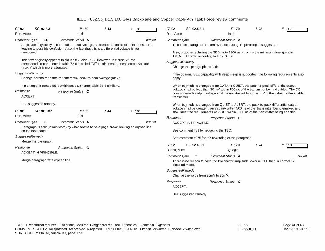
IEEE P802.3bj D1.3 100 Gb/s Backplane and Copper Cable 4th Task Force review comments
# 189Cl 92 SC 92.8.3 P 169 L 13
Comment Type ERAmplitude is typically half of peak-to-peak voltage, so there's a contradiction in terms here, leading to possible confusion. Also, the fact that this is a differential voltage is not mentioned.
This text originally appears in clause 85, table 85-5. However, in clause 72, the corresponding parameter in table 72-6 is called "Differential peak-to-peak output voltage (max.)" which is more adequate.
SuggestedRemedyChange parameter name to "differential peak-to-peak voltage (max)".
If a change in clause 85 is within scope, change table 85-5 similarly.
ACCEPT.
Use suggested remedy.
Comment Status A
Response Status C
bucket
Ran, Adee Intel
Response
# 163Cl 92 SC 92.8.3.1 P 169 L 44
Comment Type EParagraph is split (in mid-word) by what seems to be a page break, leaving an orphan line on the next page.
SuggestedRemedyMerge this paragraph.
ACCEPT IN PRINCIPLE.
Merge paragraph with orphan line
Comment Status A
Response Status C
bucket
Ran, Adee Intel
Response
# 207Cl 92 SC 92.8.3.1 P 170 L 23
Comment Type TText in this paragraph is somewhat confusing. Rephrasing is suggested.
Also, propose replacing the TBD ns to 1100 ns, which is the minimum time spent in TX_ALERT state according to table 82-5a.
SuggestedRemedyChange this paragraph to read:
If the optional EEE capability with deep sleep is supported, the following requirements also apply:
When tx_mode is changed from DATA to QUIET, the peak-to-peak differential output voltage shall be less than 30 mV within 500 ns of the transmitter being disabled. The DC common-mode output voltage shall be maintained to within mV of the value for the enabled transmitter.
When tx_mode is changed from QUIET to ALERT, the peak-to-peak differential output voltage shall be greater than 720 mV within 500 ns of the transmitter being enabled and shall meet the requirements of 92.8.1 within 1100 ns of the transmitter being enabled.
ACCEPT IN PRINCIPLE.
See comment #88 for replacing the TBD.
See comment #275 for the rewording of the paragraph.
Comment Status A
Response Status C
Ran, Adee Intel
Response
# 250Cl 92 SC 92.8.3.1 P 170 L 24
Comment Type TThere is no reason to have the transmitter amplitude lower in EEE than in normal Tx disabled mode.
SuggestedRemedyChange the value from 30mV to 35mV.
ACCEPT.
Use suggested remedy.
Comment Status A
Response Status C
bucket
Dudek, Mike QLogic
Response
TYPE: TR/technical required ER/editorial required GR/general required T/technical E/editorial G/general Cl 92SC 92.8.3.1
Page 41 of 681/27/2013 9:02:13
SORT ORDER: Clause, Subclause, page, line COMMENT STATUS: D/dispatched A/accepted R/rejected RESPONSE STATUS: O/open W/written C/closed Z/withdrawn

IEEE P802.3bj D1.3 100 Gb/s Backplane and Copper Cable 4th Task Force review comments
# 239Cl 92 SC 92.8.3.1 P 170 L 25
Comment Type EOne sentance in this paragraph doesn't make sense."When the transmitter is disabled, the peak-to-peak differential output voltage shall be greater than 720mV within 500ns of the transmitter being enabled [...]"
SuggestedRemedyUse editorial license to correct grammer to clarify the meaning of the sentance. Such as "When waking from EEE mode, [...]"
ACCEPT IN PRINCIPLE.
See comment #275.
Comment Status A
Response Status C
Kochuparambil, Beth Cisco Systems
Response
# 275Cl 92 SC 92.8.3.1 P 170 L 25
Comment Type TRThe peak to peak amplitude of the signal at TP2 is unlikely to be 720mV with 10.37dB loss between TP0 and TP2. This is an un-realistically large voltage to be achieved.
SuggestedRemedyEither a) Preferably reduce the requirement from 720mV to 220mV or b) change the test point to TP0 by adding "at TP0" between "differential output voltage" and "Shall be greater than 720mV".
ACCEPT IN PRINCIPLE.
The requirement applies for when tx_mode=ALERT, i.e. a square wave with a period of 16 UI is transmitted and the transmitter equalizer coeffiicents are set to their preset values. Thus, there will be no de-emphasis and the TP0-TP2 should have a limited impact.
Change:"When the transmitter is disabled, the peak-to-peak differential output voltage shall be greater than 720 mV within 500 ns of the transmitter being enabled and shall meet the requirements of 92.8.1 within TBD ns of the transmitter being enabled."
To:"When the transmitter is disabled, the peak-to-peak differential output voltage shall be greater than 720 mV within 500 ns of the transmitter being enabled. The transmitter is enabled by the assertion of tx_mode=ALERT and this requirement applies when the transmitted symbols are the periodic pattern defined in 92.7.2 and the transmitter equalizer coefficients are assigned their preset values. The transmitter shall meet the requirements of 92.8.3 within TBD ns of the transmitter being enabled." [TBD set by #88]
Make similar changes to 93.
Comment Status A
Response Status C
Dudek, Mike QLogic
Response
# 249Cl 92 SC 92.8.3.1 P 170 L 26
Comment Type TIncorrect reference. Subclause 92.8.1 does not give the requirements for the trasmitter.
SuggestedRemedyChange reference from 92.8.1 to 92.8.3
ACCEPT.
Comment Status A
Response Status C
Dudek, Mike QLogic
Response
TYPE: TR/technical required ER/editorial required GR/general required T/technical E/editorial G/general Cl 92SC 92.8.3.1
Page 42 of 681/27/2013 9:02:13
SORT ORDER: Clause, Subclause, page, line COMMENT STATUS: D/dispatched A/accepted R/rejected RESPONSE STATUS: O/open W/written C/closed Z/withdrawn

IEEE P802.3bj D1.3 100 Gb/s Backplane and Copper Cable 4th Task Force review comments
# 88Cl 92 SC 92.8.3.1 P 170 L 26
Comment Type TWhen the transmitter is disabled, it shall meet the requirements of 92.8.1within TBD ns of the transmitter being enabled. TBD should be replaced with a value.
SuggestedRemedyReplace "TBD ns" with 1 microsecond. Update PICS TC10 accordingly.
ACCEPT.
Comment Status A
Response Status C
Healey, Adam LSI Corporation
Response
# 251Cl 92 SC 92.8.3.1 P 170 L 26
Comment Type TThe time to be within specification after turning on in EEE is not defined (TBD)
SuggestedRemedyUse the same time as is used for 10GBASE-KR. Replace TBD with 5us.
ACCEPT IN PRINCIPLE.
See comment #88.
Comment Status A
Response Status C
Dudek, Mike QLogic
Response
# 190Cl 92 SC 92.8.3.2 P 170 L 36
Comment Type ERMissing period or full stop after "Ohm"
SuggestedRemedyAdd it.
ACCEPT.
Use suggested remedy.
Comment Status A
Response Status C
bucket
Ran, Adee Intel
Response
# 146Cl 92 SC 92.8.3.2 P 171 L 17
Comment Type TRBy definition, the measurement includes the measurement system noise. If it should be excluded or calibrated, then the text should describe how it should be done.
Comment applies also to clause 93.8.1.7 (which only refers back to 85.8.3.2). and to 85.8.3.2 (which may be out of scope).
The test implicitly assumes measurement system noise comparable to or below 1 mV RMS, otherwise the TX noise is under the noise floor. This may not be the case in all 25G measurement setups. It should at least be noted as a recommendation.
SuggestedRemedyChange item (8) to read
"The transmitter under test is turned off and the RMS noise of the measurement system is calculated. Denote sigma_0l and sigma_0h as this RMS value for the low-loss and high-loss cable assembly, respectively. For accurate measurement, sigma_0l and sigma_0h should be lower than 1 mV."
Add the measurement noise term to equation 92-2:
RMSl_dev <= sqrt(sigma_l^2 + sigma_0l^2 + 2^2)
Change equation 92.3 accordingly.
ACCEPT IN PRINCIPLE.
Add sentence: "It may be necessary to correct for test system noise." After sentence: "The measurement should not include the measurement system noise."
Comment Status A
Response Status C
Ran, Adee Intel
Response
TYPE: TR/technical required ER/editorial required GR/general required T/technical E/editorial G/general Cl 92SC 92.8.3.2
Page 43 of 681/27/2013 9:02:13
SORT ORDER: Clause, Subclause, page, line COMMENT STATUS: D/dispatched A/accepted R/rejected RESPONSE STATUS: O/open W/written C/closed Z/withdrawn

IEEE P802.3bj D1.3 100 Gb/s Backplane and Copper Cable 4th Task Force review comments
# 145Cl 92 SC 92.8.3.3 P 171 L 12
Comment Type TRSquare wave test pattern is from 83.5.10 which is optional to implement. A 100GBASE-CR4 PMD is likely integrated with a PMA. If the PMA does not implement this optional feature then this test cannot be performed.
Comment also applies to 93.8.1.7 although the test pattern is not explicitly refernced there. It also applies to clause 85.8.3.2.
SuggestedRemedyFurther discussion is required, but for the time being, add editor's notes that this text should be changed to make sure the test can be performed.
Some options for rectification (neither is perfect):1. Change 83 to make the square wave pattern mandatory2. Add a mandatory square wave pattern function in the PMD management3. Change the TX noise test to use a different apttern and method (e.g. distortion analysis as done in clause 94).4. (recommended) specify that a CR4 PMD must be attached to a PMA which support s the optional square wave test pattern.
REJECT.
Generation of the required test signal might be achievable by other means (e.g., loopback, external generator) for some devices. In these cases, a built in test generator is not required.
Comment Status R
Response Status C
Ran, Adee Intel
Response
# 147Cl 92 SC 92.8.3.4.1 P 172 L 43
Comment Type TRIf peak value of p(k) is 0.5 of v_f, it means that the rise time of a step at TP2 (in preset setting) is 2 UI. This is not reasonable; the TXFFE coefficients won't be able to compensate for the combination of such a slow TX and a long cable.
For comparison, clause 85 value is 0.63 of "TX DC amplitude" (which is equivalent to v_f) with the same TXFFE coefficient range, and similar insetion loss assumption for both cable and host board.
SuggestedRemedyChange requirement to 0.63 x v_f here and in table 92-6, also update PICS item TC16 accordinlgy.
REJECT.
The host loss basis for 85 (TP2) (~6.5 dB) is different than 92 (~10.3 dB).
Comment Status R
Response Status C
Ran, Adee Intel
Response
# 148Cl 92 SC 92.8.3.4.2 P 172 L 50
Comment Type TRThe linear fit error requirement is based on the measurement procedure defined in 85.8.3.3. This procedure does not address measurement noise (it only recommends "averaging multiple waveform captures", which may reduce noise to its mean, but not below).
It is possible that limited resolution of scopes and other measurement noises dominate the measurement results and prevent achieving the required normalized error.
To meausre the TX characteristics, one should be allowed to measure the noise and calibrate the measurement accordigly. One way of doing that is to connect a precision sine wave generator in place of the DUT, generate a sine wave with the same amplitude as the TX, capture the waveform, calculate a sinusoidal fit, and measure the fitting error. The noise correction obtained from this procedure should be limited in order to ensure meaningful results.
SuggestedRemedyMy proposed change is a detailed description. Editorial license is granted.
Change this paragraph to read:
The linear fit noise shall be limited by the following procedure (using definitions in 85.8.3.3).
1. Denote E_RMS as the RMS of e(k).2. Connect a sine wave generator in place of the DUT and set it frequency to 12.9806 GHz and its amplitude to the peak value of p(k).3. Capture the waveform of the sine wave signal, with the same method and settings used to capture y(k). Denote the result as y_cal(k).4. Denote Y_cal(n) the two-sided FFT of y_cal(k).5. Calculate the normalized measurement noise N_RMS_norm as the result of:
N_POWER = sum (f from 0 to M*fBaud) (abs(f) ^2) - 2*sum(f from 12.85 GHz to 13.11 GHz) (abs(f) ^2)N_RMS_norm = sqrt(N_POWER)/peak(p(k))
For meaningful measurements, it is recommended that N_RMS_norm be less than 0.01.
6. Denote E_cal_RMS as sqrt( (E_RMS/peak(p(k))^2 - min(N_RMS_norm, 0.01)^2) ) (to exclude calibrated measurement noise up to 0.01 of peak(p(k))).
e_cal_RMS shall be less than 0.037.
REJECT.
The procedure in 85.3.3.3 recommends waveform averaging to reduce noise. It unclear why this is inadequate. In addition, if noise compensation is required, test systems may provide equivalent or superior algorithms relative to the proposed remedy. The draft should not specify the calibration procedure.
Comment Status R
Response Status C
Ran, Adee Intel
Response
TYPE: TR/technical required ER/editorial required GR/general required T/technical E/editorial G/general Cl 92SC 92.8.3.4.2
Page 44 of 681/27/2013 9:02:13
SORT ORDER: Clause, Subclause, page, line COMMENT STATUS: D/dispatched A/accepted R/rejected RESPONSE STATUS: O/open W/written C/closed Z/withdrawn

IEEE P802.3bj D1.3 100 Gb/s Backplane and Copper Cable 4th Task Force review comments
# 164Cl 92 SC 92.8.3.5 P 173 L 40
Comment Type EI assume the "Note" refers to the recommended maximum insertion loss, rather than the actual value.
SuggestedRemedyinsert "recommended maximum" beteen "the" and "insertion".
ACCEPT.
Use suggested remedy
Comment Status A
Response Status C
bucket
Ran, Adee Intel
Response
# 252Cl 92 SC 92.8.3.5 P 173 L 40
Comment Type TThe insertion loss is not required to be a specific value.
SuggestedRemedyChange "insertion loss" to "recommended maximum insertion loss"
ACCEPT IN PRINCIPLE.
See comment #164
Comment Status A
Response Status C
bucket
Dudek, Mike QLogic
Response
# 192Cl 92 SC 92.8.3.5 P 174 L 5
Comment Type ERY axis label says "Max and Min" but only maximum is defined and shown.
SuggestedRemedyChange the y-axis label to "Max Insertion Loss - Tx or Rx PCB (dB)".
ACCEPT IN PRINCIPLE.
Change the y-axis label Insertion Loss (dB) for consistency
Comment Status A
Response Status C
bucket
Ran, Adee Intel
Response
# 149Cl 92 SC 92.8.3.6.1 P 174 L 37
Comment Type TRComment also applies to 93.8.1.8.
Current definition of Even-odd jitter is based on the polarity of the pulses (compare positive pulses and negative pulses). This can bias the results due to any effect that causes positive/negative width difference rather than the even/odd that we actually want to limit. One such effect is difference between rise and fall times, but there may be others as well.
The combined effect of even/odd and positive/negative jitter can lead to inconsistend results (depending on whether they add or cancel each other).
If the test pattern is two periods of an odd-length base pattern (such as PRBS9), then the positive pulses occur at even indices in one period and at odd indices in the other. Choosing pulses from only one of the two periods may cause differrent results depending on which of the two periods is selected.
It is important that the measurement instructions follow what we actually want to measure.
Defining a procedure that would cover both even- and odd-length arbitrary patterns is difficult. But we already have a well-defined method in clause 94 that is tailored to measure EOJ rather than polarity-related jitter. It is proposed to use that method, instead of the current definitions.
SuggestedRemedyDelete the first two paragraphs of 92.8.3.6.1.
Refer to the test pattern and measurement method defined in 94.3.12.8.2, or copy and modify it, with editorial license, here and in 93.8.1.8.
ACCEPT IN PRINCIPLE.
“Even-odd jitter is measured on two repetitions of a repeating pattern with an odd number of bits and at least two transitions between one and zero or zero and one. PRBS9 is such a pattern. The deviation of the time of each transition from an ideal clock at the signaling rate is measured. Even-odd jitter is defined as the magnitude of the difference between the average deviation of all even-numbered transitions and the average deviation of all odd-numbered transitions, where determining if a transition is even or odd is based on possible transitions but only actual transitions are measured and averaged.
Even-odd jitter shall be less than or equal to 0.035 UI regardless of the transmit equalization setting.
NOTE-Even-odd jitter has been referred to as duty cycle distortion by other Physical Layer specifications for operation over electrical backplane or twinaxial copper cable assemblies (see 72.7.1.9). The term even-odd jitter is used here to distinguish it from the duty cycle distortion referred to by Physical Layer specifications for operation over fiber optic cabling.”
Comment Status A
Response Status C
Ran, Adee Intel
Response
TYPE: TR/technical required ER/editorial required GR/general required T/technical E/editorial G/general Cl 92SC 92.8.3.6.1
Page 45 of 681/27/2013 9:02:13
SORT ORDER: Clause, Subclause, page, line COMMENT STATUS: D/dispatched A/accepted R/rejected RESPONSE STATUS: O/open W/written C/closed Z/withdrawn

IEEE P802.3bj D1.3 100 Gb/s Backplane and Copper Cable 4th Task Force review comments
# 106Cl 92 SC 92.8.3.6.1 P 174 L 46
Comment Type TThis says "The reference voltage for pulse width measurements is the mid-point between the positive pulse amplitude and the negative pulse amplitude" while above, 92.8.3.6 says "The voltage threshold for the measurement of BER or crossing times is the mid-point (0 V) of the AC-coupled differential signal." It would be better to be consistent. Also, for a slow signal as is allowed here, the shorter pulses shrink in height, biasing the threshold to reduce the apparent even-odd jitter; this creates a major error. Changing the emphasis also changes the apparent even-odd jitter with this definition.Instead, even-odd jitter can be found using an extension of the DDJ method in 85.8.3.8, so one measurement can provide two measured parameters.A definition should specify the pattern, although the method here is a convenient diagnostic.Incidentally "pulse level" would be more relevant than "pulse amplitude".
SuggestedRemedyReplace the first paragraph with:withEven-odd jitter is defined for PRBS9. A correct measurement of even-odd jitter requires that the period of the test pattern is an even number of bits, so the test pattern for the purpose of even-odd jitter measurement must be two periods of the PRBS9.
Replace the second paragraph with:Even-odd jitter is defined to be the magnitude of the difference between the mean time of all even-numbered crossings and the mean time of all odd-numbered crossings (see Figure 85-6 for an example of crossing numbering).
Put the second paragraph first.
Consider adding an informative NOTE describing the method of measuring 8 bits of alternating polarity.
Give editor licence to improve the text.
ACCEPT IN PRINCIPLE.
See comment #149.
Comment Status A
Response Status C
Dawe, Piers IPtronics
Response
# 278Cl 92 SC 92.8.3.6.4 P 175 L 19-2
Comment Type TRThis paragraph on effective RJ is inaccurate, self-inconsistent, and confusion
SuggestedRemedyReplace the text with the following new paragraph:
The effective random jitter (RJ) of a signal is defined as the difference between the TJ and effective deterministic jitter (DJ). Effective DJ is derived from the BER vs sampling time distribution. BER vs sampling time distribution can also be obtained from jitter probability distribution via integration. The estimation procedure is as follows.
a) Convert the BER vs sampling distribution to Q vs sampling time distribution, via Q(ts)= sqrt(2) erfinv( 1-(1/TD) BER (ts)), where TD is the transition density and is assumed as 0.5, and erfinv is inverse error function
b) Measure the sampling time distance from Q(ts) distribution for Q6 = 4.753, and denote it as TJ6, repeat the similar measurement for Q9 = 5.998, and denote it as TJ9
c) Effective DJ is calculated as DJ = (Q9xTJ6-Q6xTJ9)/(Q9-Q6) d) Effective RJ is calculated as RJ=TJ-DJ
ACCEPT IN PRINCIPLE.
Replace the second sentence in 92.8.3.6.4 with:"Effective DJ is derived from the measured jitter distribution as follows."
Comment Status A
Response Status C
Li, Mike Altera
Response
# 193Cl 92 SC 92.8.4 P 175 L 42
Comment Type ERMissing space before "The", page break leaving an orphan line on next page, and missing period at end of sentence.
SuggestedRemedyAdd space, join orphan line to paragraph, add period.
ACCEPT.
Use suggested remedy.
Comment Status A
Response Status C
bucket
Ran, Adee Intel
Response
TYPE: TR/technical required ER/editorial required GR/general required T/technical E/editorial G/general Cl 92SC 92.8.4
Page 46 of 681/27/2013 9:02:13
SORT ORDER: Clause, Subclause, page, line COMMENT STATUS: D/dispatched A/accepted R/rejected RESPONSE STATUS: O/open W/written C/closed Z/withdrawn

IEEE P802.3bj D1.3 100 Gb/s Backplane and Copper Cable 4th Task Force review comments
# 68Cl 92 SC 92.8.4.2 P 176 L 46
Comment Type EEquation 92-6 now has the frequency range within the curly brackets so stating the frequency range again below the equation is not needed and is inconsistent with the other equations of this type.
SuggestedRemedyDelete "for 0.01 GHz <= f <= 19 GHz" from below Equation 92-6
ACCEPT.
Use suggested remedy.
Comment Status A
Response Status C
bucket
Anslow, Pete Ciena
Response
# 253Cl 92 SC 92.8.4.3.1 P 177 L 47
Comment Type TIn Figure 92-7 there is no need to have Receivers in the test equipment.
SuggestedRemedyReplace "4 Rx" with 4 Terminations (Rx).
ACCEPT IN PRINCIPLE.
Replace "4 Rx" with "4 Rx terminations"
Comment Status A
Response Status C
bucket
Dudek, Mike QLogic
Response
# 276Cl 92 SC 92.8.4.3.4 P 179 L 3
Comment Type TRThere is a sign issue in equation 92-7. Increasing values of attenuation are given by more positive values of a4, however this equation would decrease the value of a4 for faster risetimes.
SuggestedRemedyChange from (Tr^2 - 19^2) to (19^2-Tr^2)
ACCEPT.
Use suggested remedy.
Comment Status A
Response Status C
bucket
Dudek, Mike QLogic
Response
# 254Cl 92 SC 92.8.4.3.5 P 179 L 13
Comment Type TWe have changed the training pattern somewhat and this reference is now incorrect.
SuggestedRemedyChange 72.6.10.2 to 92.7.12
ACCEPT.
Use suggested remedy
Comment Status A
Response Status C
bucket
Dudek, Mike QLogic
Response
# 150Cl 92 SC 92.8.4.3.5 P 179 L 18
Comment Type TRScrambled idle, like any data, is striped across the four lanes in a way that is not easily recoverable when looking at a single lane in the RX PMD. Also, generatuing a single-lane portion of scrambled idle requires a complex pattern generator.
Using a PCS-oriented data pattern for BER testing at the PMD interface does not make architectural sense, and would require additional hardware in the PMA.
For BER testing at the PMD, only PRBS31 should be used, and that would require the attached PMA to support PRBS31 checking.
SuggestedRemedySpecify using PRBS31 as the BER test pattern.
Add a requirement that a PMA attached to a 100GBASE-CR4 PMD must support the ability to check received PRBS31 test patterns (PRBS31_Rx_checker_ability, refer to 83.5.10).
May be OBE if 4-lane, MAC-level FER test is adopted instead.
ACCEPT IN PRINCIPLE.
Change "scrambled idle" to "scrambled idle encoded by RS-FEC".
Grant editorial license.
Other methods to check test patterns other than PMA are possible and therefore imposing requirement on PMA is unnecessary and possibly burden implementations.
Comment Status A
Response Status C
Ran, Adee Intel
Response
TYPE: TR/technical required ER/editorial required GR/general required T/technical E/editorial G/general Cl 92SC 92.8.4.3.5
Page 47 of 681/27/2013 9:02:13
SORT ORDER: Clause, Subclause, page, line COMMENT STATUS: D/dispatched A/accepted R/rejected RESPONSE STATUS: O/open W/written C/closed Z/withdrawn

IEEE P802.3bj D1.3 100 Gb/s Backplane and Copper Cable 4th Task Force review comments
# 194Cl 92 SC 92.8.4.5 P 179 L 28
Comment Type ERAC coupling is in the cable assembly, so this subclause is out of place. It should be under 92.10, where currently there is no mention of AC coupling at all.
SuggestedRemedyPrune and graft.Note that there are references to this subclause, they should be updated.
ACCEPT IN PRINCIPLE.
See comment #151.
Comment Status A
Response Status C
Ran, Adee Intel
Response
# 130Cl 92A SC 4 P 305 L 39
Comment Type TREquation 92A-1 is not consistant with the TP0 to TP2 loss where coefficent SQRT(F) and f are about the same, but equation 92A-1 linear term is twice the SQRT term. Propose to use scale version of equation 92-4.
Same comment was submitted aginst D1.2 comment 222. Removing the connector loss which is only 1.2 dB will not result in the linear term of the host PCB to incrase by factor of 2! I am trying to make the host PCB to be consistant with the TP0 to TP2a loss.
SuggestedRemedyIf equation 92-4 is multipled by 0.7 then loss at 12.89 Ghz will be 6.8 dB IL_Prop=0.0565+0.4263*sqrt(f)+0.4045*f where f is from 0.01 to 18.75 GHz.
ghiasi_01_0113 will proivde the supporting material
REJECT.
This comment was WITHDRAWN by the commenter.
Comment Status D
Response Status Z
Ghiasi, Ali Broadcom
Proposed Response
# 165Cl 92A SC 92A.2 P 305 L 18
Comment Type EText points to 93.8.1, but the characteristics there refer to TP0a, not TP0.
Comment applies also to 92A.3 with TP5/TP5a instead.
SuggestedRemedyEither change TP0 to TP0a, or change "are defined in 93.8.1" to "are the same as those defined in 93.8.1 for TP0a".
ACCEPT IN PRINCIPLE.
The transmitter characteristics at TP0 are constrained at TP0a by 93.8.1.
The receiver characteristics at TP5 are constrained at TP5a by 93.8.2.
Comment Status A
Response Status C
Ran, Adee Intel
Response
# 246Cl 92A SC 92A.5 P 307 L 25
Comment Type TThe 0.5m cable (minimum insertion loss)is no longer defined by max values of the polynomial coefficients. It is now given in Equation 92-11
SuggestedRemedyChange "is the minimum 0.5m cable assembly insertion loss using Equation(92-8)and the maximum allowed values of the polynomial coefficients a1, a2, and a4 given in Table 92-11 corresponding to the minimum insertion loss at 12.8906 GHz." to "is the minimum 0.5m cable assembly insertion loss using Equation(92-11)
ACCEPT IN PRINCIPLE.
[CommentType not specified. Set to T.]
Change
"is the minimum 0.5m cable assembly insertion loss using Equation(92-8)and the maximum allowed values of the polynomial coefficients a1, a2, and a4 given in Table 92-11 corresponding to the minimum insertion loss at 12.8906 GHz."
to
"is the minimum 0.5m cable assembly insertion loss given in Equation (92-11) and illustrated in Figure 92-10"
Comment Status A
Response Status C
Dudek, Mike QLogic
Response
TYPE: TR/technical required ER/editorial required GR/general required T/technical E/editorial G/general Cl 92ASC 92A.5
Page 48 of 681/27/2013 9:02:13
SORT ORDER: Clause, Subclause, page, line COMMENT STATUS: D/dispatched A/accepted R/rejected RESPONSE STATUS: O/open W/written C/closed Z/withdrawn

IEEE P802.3bj D1.3 100 Gb/s Backplane and Copper Cable 4th Task Force review comments
# 272Cl 92A SC 92A.5 P 307 L 9
Comment Type TThe Maximum insertion loss of the mated test fixture is contained in Equation 92-26 not Equation 92-27. Also using the maximum insertion loss is not really valid because the test results are to be adjusted based on any deviation from actaul printed circuit board loss from the nominal loss of the test boards. Also we have the Editors note on Page 189 pointing out that the Mated test fixture loss is 4.11dB at 12.8906GHz (which is between the minimum and maximum loss.
The same problem exists for the minimum loss on line 31
SuggestedRemedyChange this definition from "is the maximum insertion loss of the mated test fixture using Equation(92-27)" to "is the nominal insertion loss of the mated test fixture using Equation new"
Add Equation new. ILmatedTF(f)(nom) = 0.114*sqrt(f)+ 0.2869*f. (Note that this equation has 4.11dB loss at 12.8906 GHz and is scaled from the minimum loss equation 92-27).
Make the same change on line 31 (pointing to the same new equation).
Delete the editors note on page 189.
ACCEPT IN PRINCIPLE.
Change this definition from"is the maximum insertion loss of the mated test fixture using Equation(92-27)"to"is the nominal insertion loss of the mated test fixture using Equation <new number>"
Add Equation <new number>. ILmatedTFnom(f) = 0.1148*sqrt(f)+ 0.287*f. (Note that this equation has 4.11dB loss at 12.8906 GHz and is scaled from the minimum loss equation 92-27.
Make the same change on line 31 (pointing to the same new equation).
Delete the editors note on page 189.
Comment Status A
Response Status C
Dudek, Mike QLogic
Response
# 274Cl 92A SC 92A.7 P 308 L 41
Comment Type TThe ILD of the channel is being specified as exactly the same as that of the cable (equations 92-13 and 92-14) leaving nothing for the host. Also the channel performance is much better specified by the COM,
SuggestedRemedyDelete subclause 92A.7
ACCEPT.
Use suggested remedy.
Comment Status A
Response Status C
Dudek, Mike QLogic
Response
# 273Cl 92A SC 92A.8 P 309 L 12
Comment Type TAs it says in the editor's note the COM value should match that in 93.9.1
SuggestedRemedyChange the COM value to 4dB and delete the editor's note.
ACCEPT IN PRINCIPLE.
The suggested modification to the COM value is overtaken by events. See comment #36.
Delete the editor's note.
Comment Status A
Response Status C
Dudek, Mike QLogic
Response
# 227Cl 92A SC 92A.8 P 309 L 15
Comment Type TThe editor's note points out that the 3 dB COM value is already obsolete. The value in 93.9.1 was updated to 4 dB to allow for a change in the channel model used by COM.
SuggestedRemedyChange the recommended COM value from 3 dB to 4 dB.
ACCEPT IN PRINCIPLE.
Overtaken by events.
See comment #36.
Comment Status A
Response Status C
Brown, Matthew Applied Micro
Response
TYPE: TR/technical required ER/editorial required GR/general required T/technical E/editorial G/general Cl 92ASC 92A.8
Page 49 of 681/27/2013 9:02:13
SORT ORDER: Clause, Subclause, page, line COMMENT STATUS: D/dispatched A/accepted R/rejected RESPONSE STATUS: O/open W/written C/closed Z/withdrawn

IEEE P802.3bj D1.3 100 Gb/s Backplane and Copper Cable 4th Task Force review comments
# 96Cl 92A SC 92A.8 P 309 L 17
Comment Type TThe lower limit on COM for the TP0 to TP5 channel does not agree with Clause 93. They are intended to be the same.
SuggestedRemedyAlign Annex 92A and Clause 93 COM requirements.
ACCEPT IN PRINCIPLE.
Overtaken by events.
See comment #36.
Comment Status A
Response Status C
Healey, Adam LSI Corporation
Response
# 135Cl 93 SC 8.1.1 P 217 L 19
Comment Type TRTransition time min is defiend by asserting preset control to disable EQ.In cases pacakge having large ISI the min rise time can be circumvented
SuggestedRemedyRepalce note b with "Transmit equalization is adjusted to get 0 dB de-emphasis at TP0a the control ....
REJECT.
This comment was WITHDRAWN by the commenter.
Comment Status D
Response Status Z
Ghiasi, Ali Broadcom
Proposed Response
# 263Cl 93 SC 93.1 P 210 L 40
Comment Type TWith the FEC bypassed the Phy will not operate at a BER of 1e-12 when the specified (worst case channel) in 93.9 is used.
SuggestedRemedyChange "the channel specified in 93.9" to "a channel with better performance than the worst case specifications in 93.9
ACCEPT.
Comment Status A
Response Status C
Dudek, Mike QLogic
Response
# 264Cl 93 SC 93.5 P 211 L 43
Comment Type TWith the Transcoding and FEC encoding I don't think that PCS lanes always tranverse the same physical lane with or without skew.
SuggestedRemedyDelete the sentence "The Skew variation must also be limited ......."
ACCEPT IN PRINCIPLE.
Delete the sentence as suggested.
In addition, change the first sentence of the first paragraph of 93.5 to:"The Skew (relative delay) between the lanes must be kept within limits so that the information on the lanes can be reassembled by the RS-FEC sublayer."
See also #245 and #248.
Comment Status A
Response Status C
Dudek, Mike QLogic
Response
# 121Cl 93 SC 93.8.1.1 P 217 L 32
Comment Type TRRandom jitter is defined wihotut defining if the limit p-p and/or how many sigma
SuggestedRemedyAssuming the definition is at BER 1E-12 or 14 sigma for p-p, please add sigma to the random jitter
REJECT.
[Changed Subcl to 93.8.1.1 for consistent sorting.]
Table 93-4 is a summary table. See subclause reference 93.8.1.8 which completely defines effective random jitter (by reference to 92.8.3.6.4).
See #120.
Comment Status R
Response Status C
Ghiasi, Ali Broadcom
Response
TYPE: TR/technical required ER/editorial required GR/general required T/technical E/editorial G/general Cl 93SC 93.8.1.1
Page 50 of 681/27/2013 9:02:13
SORT ORDER: Clause, Subclause, page, line COMMENT STATUS: D/dispatched A/accepted R/rejected RESPONSE STATUS: O/open W/written C/closed Z/withdrawn

IEEE P802.3bj D1.3 100 Gb/s Backplane and Copper Cable 4th Task Force review comments
# 123Cl 93 SC 93.8.1.1 P 217 L 32
Comment Type TRTotal jitter is defined wihotut defining if the limit p-p and/or how many sigma
SuggestedRemedyAssuming the definition is at BER 1E-12 or 14 sigma for p-p, please add sigma to the random jitter.
This comment maybe overtaken if we exclude random jitter from Total Jitter
REJECT.
[Changed Subcl to 93.8.1.1 for consistent sorting.]
Table 93-4 is a summary table. See subclause reference 93.8.1.8 which completely defines total jitter (by reference to 92.8.3.6.2).
See #124.
Comment Status R
Response Status C
Ghiasi, Ali Broadcom
Response
# 118Cl 93 SC 93.8.1.1 P 217 L 33
Comment Type TRCurrent transmitter output allows total jitter excluding DDJ to be 0.28 UI. In cases transmitter have very low RJ then TJ which in this case can be all PJ could approch 0.28 UI, which will be more harmfull to the transmitter.
Current draft is incomplete as no test method has been provided to measure total jitter excluding DDJ, current test method would require real time scope with long record.
Comment 321 was submitted on D1.1 but wihtout consenous to make the change
SuggestedRemedyDue to lack of test method and the fact total jitter could end up to be all PJ the proposed resultion is to repalce Total jitter excluding DDJ with "Total Jitter excluding DDJ and Random Jitter" which can easly be measured by capturing PRBS9 waveform per test mehotd of 85.8.3.3.
Repalce 0.28 UI with 0.15 UI for value of Total Jitter Excluding DDJ and Random Jitter
ACCEPT IN PRINCIPLE.
[Changed Subcl to 93.8.1.1 for consistent sorting.]
Total jitter (TJ) and data dependent jitter (DDJ) are defined in 93.8.1.8 (by reference to 92.8.3.6.2 and 92.8.3.6.3 respectively). DDJ is measured from a PRBS9 test pattern which limits the required record length.
PJ, or similar uncorrelated determinstic jitter (DJ), can be constrained by limiting effective DJ excluding DDJ. Effective DJ is an intermediate result for the computation of effective random jitter (see 92.8.3.6.3).
Add a limit for "Effective determinstic jitter excluding data dependent jitter" of 0.15 UI.
See #119.
Comment Status A
Response Status C
Ghiasi, Ali Broadcom
Response
TYPE: TR/technical required ER/editorial required GR/general required T/technical E/editorial G/general Cl 93SC 93.8.1.1
Page 51 of 681/27/2013 9:02:13
SORT ORDER: Clause, Subclause, page, line COMMENT STATUS: D/dispatched A/accepted R/rejected RESPONSE STATUS: O/open W/written C/closed Z/withdrawn

IEEE P802.3bj D1.3 100 Gb/s Backplane and Copper Cable 4th Task Force review comments
# 27Cl 93 SC 93.8.1.1 P 218 L 24
Comment Type TIdentical to comment made on 92.8.3. Entire test system response, not just the filter, should be 33 GHz bandwidth. Thomson, not Thompson
SuggestedRemedyReplace with: A test system with a fourth-order Bessel-Thomson low-pass response (-3dB at 33 GHz) is to be used for all transmitter signal measurements
ACCEPT IN PRINCIPLE.
[Changed Subcl to 93.8.1.1 for consistent sorting.]
See resolution to comment #25.
Modify Clause 94 to be consistent, but with 17 GHz 3 dB bandwidth.
Comment Status A
Response Status C
Le Cheminant, Greg Agilent Technologies
Response
# 89Cl 93 SC 93.8.1.3 P 219 L 26
Comment Type TWhen the transmitter is disabled, it shall meet the requirements of 93.8.1within TBD ns of the transmitter being enabled. TBD should be replaced with a value.
SuggestedRemedyReplace "TBD ns" with 1 microsecond. Update PICS TC12 accordingly.
ACCEPT. See #88, #251, and #207.
Comment Status A
Response Status C
Healey, Adam LSI Corporation
Response
# 127Cl 93 SC 93.8.1.4 P 219 L 39
Comment Type TRTransmitter output return loss is unclear at what point is measured
SuggestedRemedyTransmitter output return loss is measured at TP0a
REJECT.
[Changed Subcl to 93.8.1.4 for consistent sorting.]
93.8.1.1 states that "unless otherwise noted, measurements of the transmitter are made at the output of a test fixture as shown in Figure 93-4." No exception is made for transmitter return loss measurements. 93.8.1 and Table 93-4 also states the transmitter characteristics are measured at TP0a.
The clause is organized this way so that the measurement point does not need to be stated repeatedly in each subclause.
Comment Status R
Response Status C
Ghiasi, Ali Broadcom
Response
# 129Cl 93 SC 93.8.1.4 P 219 L 39
Comment Type TRTrnasmitter return loss mask is unrealistic with low frequency too loose and high frequency too tight. Comment was also submitted against D1.2 comment 229, with response that this output is at TP0a and suggested equation was at TP2 so these equation can be different. However in case with min channel loss the HCB loss washes the degradation due to MDI connector, generally speaking the RL will improve for the case host channel loss is increased. They could be different but current equation 93-2 is unrealistic and not clear where it came from!
SuggestedRemedyProposed to use equation 92-512-0.5*f from 0.01 to 8 GHz5.65 -9.71*log10(f/14) from 8 to 19 GHz
See ghiasi_01_0113
ACCEPT IN PRINCIPLE.
[Changed Subcl to 93.8.1.4 for consistent sorting.]
Replace equations (93-2) and (93-7) with equation shown in slide 15 of benartsi_3bj_01a_0113 with a frequency range of 0.05 to 19 GHz.
Replace equations (94-5) and (94-15) with equation shown in slide 15 of benartsi_3bj_01a_0113 with a frequency range of 0.05 to 10 GHz.
Comment Status A
Response Status C
return_loss
Ghiasi, Ali Broadcom
Response
TYPE: TR/technical required ER/editorial required GR/general required T/technical E/editorial G/general Cl 93SC 93.8.1.4
Page 52 of 681/27/2013 9:02:13
SORT ORDER: Clause, Subclause, page, line COMMENT STATUS: D/dispatched A/accepted R/rejected RESPONSE STATUS: O/open W/written C/closed Z/withdrawn

IEEE P802.3bj D1.3 100 Gb/s Backplane and Copper Cable 4th Task Force review comments
# 104Cl 93 SC 93.8.1.4 P 219 L 39
Comment Type TI'm assuming this return loss spec is under review.To control echoes on short channels adequately, the return loss spec must extend to a frequency where the echo is adequately attenuated by something else (e.g. a filter in the receiver). If the spec stops at 13 GHz, reflections at 13.1 GHz would dominate. This applies to IC-to-IC links and also, as an IC that meets the 100GBASE-KR4 specification should be suitable for use in 100GBASE-CR4, to IC-to-cable echoes in 100GBASE-CR4, even if the cable has significant loss. Note that 100GBASE-CR4 specifies host return loss 10 MHz to 19 GHz and cable return loss 50 MHz to 19 GHz, so an implementer would have to deliver adequate performance up to 19 GHz for CR4 anyway. The equivalent OIF spec goes up to the signalling rate.
SuggestedRemedyThe new limit should extend to at least 15 GHz, preferably to 19 GHz.
ACCEPT IN PRINCIPLE.
Change the frequency range to 0.05 to 19 GHz for the following 100GBASE-KR4 limits.
Transmitter differential output return loss, Equation (93-2)Transmitter common-mode output return loss, Equation (93-3)Receiver differential input return loss, Equation (93-7), unless removed per #107Receiver common-mode output return loss, Equation (93-8), unless removed per #139 or #107Receiver differential to common-mode return loss, Equation (93-9)
See comment #129.
Comment Status A
Response Status C
return_loss
Dawe, Piers IPtronics
Response
# 132Cl 93 SC 93.8.1.4 P 219 L 40
Comment Type TRTransmitter output return loss has unrealistic shape and high frequncy is too tight and limit stop at low a frequency.
See comment 230 aginst D1.2
SuggestedRemedyPropose to use EQ 92-1 from section 92.8.3.2 as I assume these are the same chip anyway RL= 12-0.5ffrom 0.05=f=8=5.65-9.71log (f / 14)8 <= f <= 25 GHz(dB)(92-1)
see ghiasi_01_0113
ACCEPT IN PRINCIPLE.
[Changed Subcl to 93.8.1.4 for consistent sorting.]
The suggested remedy proposes the same limit as #129 but with a different frequency range. See #129.
Comment Status A
Response Status C
return_loss
Ghiasi, Ali Broadcom
Response
# 105Cl 93 SC 93.8.1.8 P 223 L 37
Comment Type T92.8.3.6 has a paragraph about jitter measurement filter and voltage threshold that applies here also.
SuggestedRemedyAdd a sentence incorporating it by reference.
ACCEPT.
Comment Status A
Response Status C
bucket
Dawe, Piers IPtronics
Response
# 99Cl 93 SC 93.8.1.8 P 223 L 41
Comment Type EUse standards language.
SuggestedRemedyChange "is characterized using the procedure defined in" to "is defined in", three times in this subclause.
ACCEPT.
Comment Status A
Response Status C
bucket
Dawe, Piers IPtronics
Response
TYPE: TR/technical required ER/editorial required GR/general required T/technical E/editorial G/general Cl 93SC 93.8.1.8
Page 53 of 681/27/2013 9:02:13
SORT ORDER: Clause, Subclause, page, line COMMENT STATUS: D/dispatched A/accepted R/rejected RESPONSE STATUS: O/open W/written C/closed Z/withdrawn

IEEE P802.3bj D1.3 100 Gb/s Backplane and Copper Cable 4th Task Force review comments
# 128Cl 93 SC 93.8.2.1 P 224 L 24
Comment Type TRReceiver return loss mask is unrealistic with low frequency too loose and high frequency too tight. Comment was also submitted against D1.2 comment 230, with response that this output is at TP0a and suggested equation was at TP2 so these equation can be different. However in case with min channel loss the HCB loss washes the degradation due to MDI connector, generally speaking the RL will improve for the case host channel loss is increased. They could be different but current equation 93-2 is unrealistic and not clear where it came from!
SuggestedRemedyProposed to use equation 92-512-0.5*f from 0.01 to 8 GHz5.65 -9.71*log10(f/14) from 8 to 19 GHz
see ghiasi_01_0113
ACCEPT IN PRINCIPLE.
[Changed Subcl to 93.8.2.1 for consistent sorting.]
Subclause reference to receiver test fixture but comment discusses receiver differential input return loss.
It is assumed the commenter intended to refer to 93.8.2.2, Equation (93-7).
See comment #129.
Comment Status A
Response Status C
return_loss
Ghiasi, Ali Broadcom
Response
# 107Cl 93 SC 93.8.2.2 P 225 L 18
Comment Type TPlease don't waste the reader's (and editor's) time.I've made this a technical comment in case we want different limits for transmitter and receiver.
SuggestedRemedyIf it is intended that receiver input return loss limit will be the same as transmitter output return loss, just refer back to Equation (93-2) and Figure 93-6.Remove other unnecessary repetition in clauses 92-94.
ACCEPT IN PRINCIPLE.
In 93.8.2.1:Remove Equation (93-6)/Figure 93-8 and refer to Equation (93-1)/Figure 93-3.
In 93.8.2.2:Remove Equation (93-7)/Figure 93-10 and refer to Equation (93-2)/Figure 93-6.
Remove Equation (93-8) and refer to Equation (93-3), unless removed per #139.
Update 92 is a similar manner.
Comment Status A
Response Status C
return_loss
Dawe, Piers IPtronics
Response
TYPE: TR/technical required ER/editorial required GR/general required T/technical E/editorial G/general Cl 93SC 93.8.2.2
Page 54 of 681/27/2013 9:02:13
SORT ORDER: Clause, Subclause, page, line COMMENT STATUS: D/dispatched A/accepted R/rejected RESPONSE STATUS: O/open W/written C/closed Z/withdrawn

IEEE P802.3bj D1.3 100 Gb/s Backplane and Copper Cable 4th Task Force review comments
# 137Cl 93 SC 93.8.2.2 P 225 L 49
Comment Type TRThere is interest to make the return loss for CL93 and 94 the same and also stated by the eidtor in comment 325 aginst D1.2. Resolution to comment 325 indicate the TBD is to be repalced with proposed limit given in comment 325 but somehow differential to common mode conversion was removed from CL93 but still exist in CL94
SuggestedRemedyPlease add differential to common mode conversion in CL93 per equation 94-17 but with limit extended to 19 GHz
25 - 20*(f/13.89) from 0.05 to 6.95 GHz15 GHz from 6.95 GHz to 13 GHz
ACCEPT IN PRINCIPLE.
[Changed Subcl to 93.8.2.2 for consistent sorting.]
Receiver differential to common-mode return loss was not removed. Refer to 93.8.2.2 and Equation (93-9).
"20-1.44*f" should be "25-1.44*f" in Equation (93-9). The correct equation is shown in Figure 93-11. Note that 20/13.89 is 1.44.
Comment Status A
Response Status C
return_loss
Ghiasi, Ali Broadcom
Response
# 139Cl 93 SC 93.8.2.2 P 225 L 49
Comment Type TRThere is interest to make the return loss for CL93 and 94 the same and also stated by the eidtor in comment 325 aginst D1.2. Instaed of making Cl93 and 94 identical during last comment resoution cycle we end up removing differential to common mode conversion from CL93 instead of removing common mode
SuggestedRemedyRemove common mode return loss limit of 93-8
ACCEPT.
[Changed Subcl to 93.8.2.2 for consistent sorting.]
Removal of receiver common-mode return loss limits was not part of the adopted response to Draft 1.2 comments #325 or #215.
Remove receiver common mode return loss in 93 and 94.
Comment Status A
Response Status C
return_loss
Ghiasi, Ali Broadcom
Response
# 37Cl 93 SC 93.8.2.3 P 226 L 32
Comment Type TTable 93-7 and the 100GBase-KR4 interference tolerance test lacks a correlation to the channel operating margin methodology.
SuggestedRemedyWill supply a presentation.
REJECT.
This comment was WITHDRAWN by the commenter.
Comment Status D
Response Status Z
bucket
Ben-Artsi, Liav Marvell
Proposed Response
# 35Cl 93 SC 93.8.2.3 P 226 L 38
Comment Type TRomit test 2 and test 3make test similar to clause 94
SuggestedRemedyIn table 93-71)replace the BER at MAC or simile . i.e. value = 1e-122) add rss DFE line to tablemake it optional to test with a minimally compliant transmitter so link training can be achieved.3) convert jitter etc to broad band noise calibration target. include procedure from clause 94.
REJECT.
This comment was WITHDRAWN by the commenter.
Comment Status D
Response Status Z
Mellitz, Richard Intel Corporation
Proposed Response
# 240Cl 93 SC 93.9.1 P 227 L 9
Comment Type TIt has not yet been proven that <=4dB COM channels align with passing 10E-12 TX/RX operation. I have concerns that the 4dB COM limits backplane channels beyond what is reasonable; continued analysis on this topic would also be beneficial.
SuggestedRemedySee Kochuparambil_01_0113
REJECT.
This comment was WITHDRAWN by the commenter.
Comment Status R
Response Status C
bucket
Kochuparambil, Beth Cisco Systems
Response
TYPE: TR/technical required ER/editorial required GR/general required T/technical E/editorial G/general Cl 93SC 93.9.1
Page 55 of 681/27/2013 9:02:13
SORT ORDER: Clause, Subclause, page, line COMMENT STATUS: D/dispatched A/accepted R/rejected RESPONSE STATUS: O/open W/written C/closed Z/withdrawn

IEEE P802.3bj D1.3 100 Gb/s Backplane and Copper Cable 4th Task Force review comments
# 277Cl 93 SC 93.9.1 P 228 L 20
Comment Type TRThe minimum values of the pre-cursor and post-cursor coefficients in the COM table 93-8 do not match the required pre-cursor and post-cursor in 93.8.1.6.5
SuggestedRemedyChange the minimum pre-cursor from -0.18 to -0.22 and change the minimum post-cursor from -0.38 to -0.6
REJECT.
This comment was WITHDRAWN by the commenter.
Comment Status D
Response Status Z
bucket
Dudek, Mike QLogic
Proposed Response
# 97Cl 93A SC 93A.1 P 310 L 15
Comment Type TThe editor's note states that a separate informative annex will be added with a sample implementation when the content of Annex 93A stabilizes. In the meantime, it would be helpful to provide pointers to existing sample implementations.
SuggestedRemedyInclude a link to the Task Force "tools" page that points to a sample implementation of the COM calculation.
ACCEPT IN PRINCIPLE.
If an appropriate link exists, include it in the editor's note.
Comment Status A
Response Status C
Healey, Adam LSI Corporation
Response
# 36Cl 93a SC 93A.1.2 P 312 L 18
Comment Type TRequation 93a-5 cannot be easily amended with new data and preserve causality and passivity.see presentation
SuggestedRemedyUse new equation for Z derived from a fitting similar clause 93A.2 for a very small length of transmission line and termination.see presenation
ACCEPT IN PRINCIPLE.
Modify draft per mellitz_3bj_01b_0113 with editorial license.
Also, reduce COM target from 4 dB to 3 dB in Clauses 93 and 94.
Comment Status A
Response Status C
Mellitz, Richard Intel Corporation
Response
# 38Cl 93a SC 93a.1.2 P 312 L 18
Comment Type TThe return loss equation for TP0/TP5 as described in Eq: 93a-3,4,5 and table 93a-2 is not ceherent with the measured return loss at TP0a/TP5a as described in equations 93-2, 93-7, 94-5, 94-15 as well as with cable return loss as described at equations: 92-1 and 92-5.
SuggestedRemedywill supply a presentation
ACCEPT IN PRINCIPLE.
See #129 for transmitter return loss.See #128 for receiver return lossSee #36 for driver/load reflection coefficient for COM.
Comment Status A
Response Status C
return_loss
Ben-Artsi, Liav Marvell
Response
# 29Cl 93A SC 93A.1.2 P 312 L 8
Comment Type TEquations 93A-3 and 93A-4 are the opposite sign of the normal definition of reflection coefficient. I think that is due to our misinterpreting benartsi_3bj_01a_1112 slide 6. As a result I think that we are leaving out an important phase term.
SuggestedRemedyEither correct sign of 93A-3 and 93A-4 or find out from Liav what he intended and do that.
ACCEPT IN PRINCIPLE.
[Commenter set Clause to 93. Changed to 93A.]
This is overtaken by #36. See #36.
Comment Status A
Response Status C
Moore, Charles Avago Technologies
Response
# 30Cl 93A SC 93A.1.5 P 314 L 45
Comment Type TRIn equation(93A-16) sigma_isi^2 vanishes when N is large and large number of h_isi terms are zero.
SuggestedRemedychange: sigma_isi^2 = sigma_x^2*sum(H_isi^2(n))
ACCEPT IN PRINCIPLE.
See #28.
Comment Status A
Response Status C
Mellitz, Richard Intel Corporation
Response
TYPE: TR/technical required ER/editorial required GR/general required T/technical E/editorial G/general Cl 93ASC 93A.1.5
Page 56 of 681/27/2013 9:02:13
SORT ORDER: Clause, Subclause, page, line COMMENT STATUS: D/dispatched A/accepted R/rejected RESPONSE STATUS: O/open W/written C/closed Z/withdrawn

IEEE P802.3bj D1.3 100 Gb/s Backplane and Copper Cable 4th Task Force review comments
# 28Cl 93A SC 93A.1.5 P 314 L 46
Comment Type ERIn equation 93A-16 sigma^2_ISI is supposed to be the total ISI not the average.
Also in equation 93A-28, sigma^2_m also should be total interference, not average, although this is not significant.
SuggestedRemedyIn equation 93A-16 delete "N" in denominatoralsoIn equation 93A-28 delete "N" in denominator
ACCEPT.
[Clause specified as 94A. Changed to 93A.]
Equation (93A-16) and Equation (93A-28) are supposed to be the ISI variance. 1/N factor should not be included.
Comment Status A
Response Status C
Moore, Charles Avago Technologies
Response
# 31Cl 93A SC 93A.1.6.2 P 316 L 12
Comment Type TRIf equation (93A-24) is discretely evaluated the integral will be equal to the number of samples.
SuggestedRemedyAdd a note in the P_g((y) is to be normalized so that the integral = 1
REJECT.
Equation (93A-24) is not an integral. When evaluated in Equation (93A-19), the integral approaches 1 for large y as expected.
Note the discrete appromixation for the integral in Equation (93A-19) is sum{ p(yn)*dy } where yn is an element of a discrete y-axis with uniform step size dy. If the dy factor is not included, the integral then converges to 1/dy.
Comment Status R
Response Status C
Mellitz, Richard Intel Corporation
Response
# 218Cl 94 SC 94.2.1 P 240 L 22
Comment Type TThe editor's note points out that the behavior in response to tx_mode and rx_mode must be defined.
SuggestedRemedyDefine the PMA behavior in response to rx_mode and tx_mode. A proposal will be provided.
ACCEPT IN PRINCIPLE.
See comment #94.
Comment Status A
Response Status C
pma eee
Brown, Matthew Applied Micro
Response
# 94Cl 94 SC 94.2.1 P 240 L 22
Comment Type TThe editor's note highlights that the functional behavior of a Clause 94 PMA that supports the optional Energy Efficient Ethernet (EEE) capability is undefined. Also see 94.2.3 and 94.2.5.
SuggestedRemedyDefine the Clause 94 PMA behavior for the optional EEE capability.
ACCEPT IN PRINCIPLE.
Implemented the changes in brown_3bj_01a_0113 slides 3 to 7 with editorial license.
Comment Status A
Response Status C
pma eee
Healey, Adam LSI Corporation
Response
# 90Cl 94 SC 94.2.12 P 249 L 39
Comment Type TIn Table 94-4, the register numbers for PMA overhead control and status are TBD.
SuggestedRemedyDefine the register numbers.
ACCEPT IN PRINCIPLE.
See comment #228.
Comment Status A
Response Status C
pma overhead
Healey, Adam LSI Corporation
Response
TYPE: TR/technical required ER/editorial required GR/general required T/technical E/editorial G/general Cl 94SC 94.2.12
Page 57 of 681/27/2013 9:02:13
SORT ORDER: Clause, Subclause, page, line COMMENT STATUS: D/dispatched A/accepted R/rejected RESPONSE STATUS: O/open W/written C/closed Z/withdrawn
IEEE P802.3bj D1.3 100 Gb/s Backplane and Copper Cable 4th Task Force review comments
# 228Cl 94 SC 94.2.12 P 249 L 39
Comment Type TMDIO status and control register fields have been specified for the PMA overhead, but specific MDIO register address is TBD. The registers are annotated in Table 94-4 and Table 94-5.
SuggestedRemedyProvide specific MDIO register address for each of the PMA OH register fields.
ACCEPT IN PRINCIPLE.
Implement the changes proposed in brown_3bj_02_0113 slides 6 to 9.
Comment Status A
Response Status C
pma overhead
Brown, Matthew Applied Micro
Response
# 217Cl 94 SC 94.2.2 P L
Comment Type EEach sub-section under 94.2.2, except 94.2.2.3, refers the PMA in general rather than specifically the transmit portion.
SuggestedRemedyModify references the "the PMA" to "the PMA transmit process" at the following locations:page 242, line 42page 243, line 3page 243, line 50page 244, line 40page 245, line 8page 245, line 30page 245, line 48
ACCEPT.
Comment Status A
Response Status C
bucket
Brown, Matthew Applied Micro
Response
# 144Cl 94 SC 94.2.2.4 P 243 L 52
Comment Type TROverhead frame size is 348 termination blocks.
SuggestedRemedyChange 384 to 348.
ACCEPT.
Comment Status A
Response Status C
bucket
Ran, Adee Intel
Response
# 219Cl 94 SC 94.2.3 P 246 L 4
Comment Type TThe editor's note points out that the PMA transmit EEE behavior must be defined.
SuggestedRemedyDefine the PMA EEE behavior. A proposal will be provided.
ACCEPT IN PRINCIPLE.
See comment #94.
Comment Status A
Response Status C
pma eee
Brown, Matthew Applied Micro
Response
# 220Cl 94 SC 94.2.5 P 247 L 24
Comment Type TThe editor's note points out that the PMA receive EEE behavior must be defined.
SuggestedRemedyDefine the PMA receiver EEE behavior. A proposal will be provided.
ACCEPT IN PRINCIPLE.
See comment #94.
Comment Status A
Response Status C
pma eee
Brown, Matthew Applied Micro
Response
# 230Cl 94 SC 94.2.9 P 248 L 4
Comment Type TThe PMA local loopback is mandatory, not optional. It is therefore not necessary to indicate whether the loopback is supported or not. However, since there is by default an MDIO local loopback ability status bit, this bit should be always set to one for this PMA.
SuggestedRemedyIn line 4 on page 248, insert the following sentence..."The Local_loopback_ability status variable shall always be set to 1."
ACCEPT.
Comment Status A
Response Status C
pma loopback
Brown, Matthew Applied Micro
Response
TYPE: TR/technical required ER/editorial required GR/general required T/technical E/editorial G/general Cl 94SC 94.2.9
Page 58 of 681/27/2013 9:02:13
SORT ORDER: Clause, Subclause, page, line COMMENT STATUS: D/dispatched A/accepted R/rejected RESPONSE STATUS: O/open W/written C/closed Z/withdrawn

IEEE P802.3bj D1.3 100 Gb/s Backplane and Copper Cable 4th Task Force review comments
# 17Cl 94 SC 94.3.10.6.4 P 260 L 11
Comment Type TAllowing for multiple tap change requests to be made simultaneously complicates the response behavior of the PMD when the change takes a given tap to or beyond its operating range. It also highly complicates the logic needed to deal with these circumstances (both at the edge, and in the center of the EQ range), and what was applied and was not applied is when a MIN/MAX response is given is dependent upon the link partner implementation, thus it's unknown. Which can cause interoperability issues.
SuggestedRemedyChange "Coefficient increment and decrement update requests must not be sent in combination with initialize or preset."to"A tap coefficient increment or decrement update request must not be sent in combination with initialize, preset or other tap cofficient update requests."
REJECT.
[changed sub-clause from 3.10.6.4 to 94.3.10.6.4]
A similar comment against 802.3bj Draft 1.1 Clause 93 (comment 10097) was rejected with the following response.
It is agreed that Clause 72 is unclear on how the status report fields should be set when a parallel coefficient update results in a violation of the peak or steady state voltage constraints. That said, while Clause 72 allows parallel coefficient update requests, it does not require it. The implication is that an adaptation algorithm that cannot deal with ambiguity in status report corresponding to constraint violations with parallel coefficient updates may send individual coefficient updates serially. Conversely, an adaptation algorithm that is insensitive to this ambiguity may send coefficient updates in parallel if it wishes. Therefore, the initiator of coefficient updates has the ability to choose whether to send coefficient updates serially or in parallel and therefore there is no ambiguity imposed by the standard. It is an implementation consideration. The commenter does not provide sufficient justification constrain the implementation in the manner proposed in the suggested remedy.
Comment Status R
Response Status C
pmd tap control
Slavick, Jeff Avago Technologies
Response
# 16Cl 94 SC 94.3.10.6.4 P 260 L 9
Comment Type TAllowing for Coefficient change requests to "trickle" in may cause interoperabily issues since different designs will respond to the trickle in different manners.
SuggestedRemedyChange "for that tap is not_updated." to "for all taps is not_updated."
REJECT.
[changed sub-clause from 3.10.6.4 to 94.3.10.6.4]
The commenter has not sufficiently identified the need for the proposed change.
Comment Status R
Response Status C
pma tap control
Slavick, Jeff Avago Technologies
Response
# 265Cl 94 SC 94.3.11.1 P 265 L 1
Comment Type TIt would be better to use the same names for these fields as are used in Figure 94-8
SuggestedRemedyChange "and the control and status fields" to "and the coefficient update and status report fields"
ACCEPT.
Comment Status A
Response Status C
bucket
Dudek, Mike QLogic
Response
# 221Cl 94 SC 94.3.11.1.10 P 267 L 15
Comment Type TThe editor's note points out that that the diagram is intended to show a transition at any phase alignment offset (PAO), but the PRBS13 pattern is relevant to PA0 = 0.
SuggestedRemedyUpdate the diagram to correct this. A proposal will be provided.
ACCEPT IN PRINCIPLE.
See comment #95.
Comment Status A
Response Status C
pmd alert signal
Brown, Matthew Applied Micro
Response
TYPE: TR/technical required ER/editorial required GR/general required T/technical E/editorial G/general Cl 94SC 94.3.11.1.10
Page 59 of 681/27/2013 9:02:13
SORT ORDER: Clause, Subclause, page, line COMMENT STATUS: D/dispatched A/accepted R/rejected RESPONSE STATUS: O/open W/written C/closed Z/withdrawn

IEEE P802.3bj D1.3 100 Gb/s Backplane and Copper Cable 4th Task Force review comments
# 95Cl 94 SC 94.3.11.1.10 P 267 L 17
Comment Type TThe editor's note states that the PRBS13 sequence in Figure 94-9 is based on a PAO of zero and the sequence will be different for otherPAO values. This clarification is relevant even after final publication (at which point the editor's note is removed).
SuggestedRemedyIncorporate this information into subclause text or figure or generalize the figure so that it is correct regardless of PAO value. Delete the editor's note.
ACCEPT IN PRINCIPLE.
Add then following text after the reference to Figure 94-9: “The values for thePRBS13 in Figure 94-9 are specific to a transition with a PAO of zero on Lane 0. The values are different for other PAO values or lane number.”
Comment Status A
Response Status C
pmd alert signal
Healey, Adam LSI Corporation
Response
# 233Cl 94 SC 94.3.11.1.3 P 266 L 5
Comment Type TAs specified in 94.3.11.1.9, the "receiver ready" status field alway indicate 1.
SuggestedRemedyIn Table 94-13, in the description column for "receiver ready" replace the text with "Always set to 1."
ACCEPT.
Comment Status A
Response Status C
pmd alert frame
Brown, Matthew Applied Micro
Response
# 232Cl 94 SC 94.3.11.1.6 P 266 L
Comment Type TThe PMA/PMD transmitter cannot differentiate between WAKE and REFRESH modes since tx_mode indicates only ALERT and DATA for both. The EEE mode indication is therefore not usable.
SuggestedRemedyRemove the EEE state bit from the ALERT frame status field.Delete section 94.3.11.1.6.In Table 94-13, indicate cells 17:16 as being reserved.
ACCEPT.
Comment Status A
Response Status C
pmd alert frame
Brown, Matthew Applied Micro
Response
# 266Cl 94 SC 94.3.12 P 268 L 10
Comment Type TThe Differential Peak maximum voltage with transmitter enabled has different values in Table 94-14 (1110mV) and in section 94.3.12.3 (1200mV). Also this value should be at least as large as twice the steady-state voltage Vf max (600mV)in Table 94-14 and 94.3.12.6.2
SuggestedRemedyMake them consistent. I suggest the value in Table 94-14 is changed from 1110mV to 1200mV.
ACCEPT.
The commenter points out an error in the implementation of comment #151 against draft 1.2.
Comment Status A
Response Status C
bucket
Dudek, Mike QLogic
Response
# 216Cl 94 SC 94.3.12 P 268 L 19
Comment Type TIn Table 94-14, the value for minimum transition time is TBD.
SuggestedRemedyProvide a value for minimum transition time. A proposal on the subject is expected.
ACCEPT IN PRINCIPLE.
[CommentType not specified. Set to T.]
See comment #222.
Comment Status A
Response Status C
pmd tx transition time
Brown, Matthew Applied Micro
Response
# 131Cl 94 SC 94.3.12.1 P 268 L 19
Comment Type TRRepalce TBD for rise and fall times
SuggestedRemedyScale value of CL92/93 by factor of 2 so repalce the TBD with rise time of 16 ps
ACCEPT IN PRINCIPLE.
[changed sub-clause from 3.12.1 to 94.3.12.1]
See comment #222.
Comment Status A
Response Status C
pmd tx transition time
Ghiasi, Ali Broadcom
Response
TYPE: TR/technical required ER/editorial required GR/general required T/technical E/editorial G/general Cl 94SC 94.3.12.1
Page 60 of 681/27/2013 9:02:14
SORT ORDER: Clause, Subclause, page, line COMMENT STATUS: D/dispatched A/accepted R/rejected RESPONSE STATUS: O/open W/written C/closed Z/withdrawn

IEEE P802.3bj D1.3 100 Gb/s Backplane and Copper Cable 4th Task Force review comments
# 122Cl 94 SC 94.3.12.1 P 268 L 19
Comment Type TRTransition time min is defiend by asserting preset control to disable EQ.In cases pacakge having large ISI the min rise time can be circumvented
SuggestedRemedyRepalce note b with "Transmit equalization is adjusted to get 0 dB de-emphasis at TP0a the control ....
REJECT.
This comment was WITHDRAWN by the commenter.
[changed sub-clause from 3.12.1 to 94.3.12.1]
Comment Status D
Response Status Z
pmd tx transition time
Ghiasi, Ali Broadcom
Proposed Response
# 267Cl 94 SC 94.3.12.3 P 269 L 47
Comment Type TThere is no reason to allow the output voltage with EEE to be larger than the Tx disabled output voltage
SuggestedRemedyChange 35mV to 30mV to match the value in Table 94-14.
ACCEPT.
Comment Status A
Response Status C
bucket
Dudek, Mike QLogic
Response
# 91Cl 94 SC 94.3.12.5 P 270 L 35
Comment Type TEditor's note states that suitable pattern, methodology, and values for [minimum] transition time are needed.
SuggestedRemedyDefine pattern, methodology, and values. Update PICS TC16 accordingly.
ACCEPT IN PRINCIPLE.
See comment #222.
Remove editor's note.
Comment Status A
Response Status C
pmd tx transition time
Healey, Adam LSI Corporation
Response
# 222Cl 94 SC 94.3.12.5 P 270 L 36
Comment Type TThe editor's note points out that pattern, methodology, and value are required for transition time. Specifically, a lower bound on transition time is required.
SuggestedRemedyProvide pattern, methodology, and value. A proposal will be provided.
ACCEPT IN PRINCIPLE.
See lusted_3bj_01a_0113 slide 5 with slide 4 as a reference. Implement with editorial license.
Update Table 94-14 transition time TBD.
Instead of referring to 68.6.2 to 52.9.5, with the exception of a shorter run length.
Comment Status A
Response Status C
pmd tx transition time
Brown, Matthew Applied Micro
Response
# 24Cl 94 SC 94.3.12.5 P 270 L 51
Comment Type EI believe that "....where bits 1 to 9 are the run of 9 zeros." was intended to read "...where bits 1 to 9 are the run of 9 ones". This is what the previous text implies, and a PRBS9 pattern cannot have a run of 9 zeroes (unless it is inverted).
SuggestedRemedyreplace word 'zeros' with 'ones' as indicated.
ACCEPT IN PRINCIPLE.
[changed sub-clause form 3.12.5 to 94.3.12.5]
Overtaken by events.
See response to comment #222.
Comment Status A
Response Status C
pmd tx transition time
Le Cheminant, Greg Agilent Technologies
Response
TYPE: TR/technical required ER/editorial required GR/general required T/technical E/editorial G/general Cl 94SC 94.3.12.5
Page 61 of 681/27/2013 9:02:14
SORT ORDER: Clause, Subclause, page, line COMMENT STATUS: D/dispatched A/accepted R/rejected RESPONSE STATUS: O/open W/written C/closed Z/withdrawn

IEEE P802.3bj D1.3 100 Gb/s Backplane and Copper Cable 4th Task Force review comments
# 229Cl 94 SC 94.3.12.6.2 P 272 L 50
Comment Type TThe peak value of p(k) should be increased to enforce faster transition time at the transmitter. It is reasonable to expect that the transition time should be similar to that achievable by a PAM2 transmitter. In other words, the assumed transmitter bandwidth may be doubled and the peak value of p(k) can be derived on this basis. The current transmitter bandwidth assumption is 0.375*fb.
SuggestedRemedySelect a value for peak value of p(k) such that worst case transmitter bandwidth is 0.75*fb.
REJECT.
This comment was WITHDRAWN by the commenter.
Comment Status D
Response Status Z
bucket
Brown, Matthew Applied Micro
Proposed Response
# 268Cl 94 SC 94.3.12.6.2 P 272 L 50
Comment Type TThe Peak value in table 94-14 should match the Peak value listed in this sub-clause.
SuggestedRemedyMake them match. I suggest Change 0.85*Vf to 0.8*Vf here.
ACCEPT IN PRINCIPLE.
The commenter points out an error in the implementation of comment #247 against draft 1.2. The value for the peak of p(k) in the adopted response was 0.85*vf.
In Table 94-14, change the value for "linear fit pulse peak (min)" from 0.8*vf to 0.85*vf.
Comment Status A
Response Status C
pmd tx peak p(k)
Dudek, Mike QLogic
Response
# 133Cl 94 SC 94.3.12.8 P 274 L 32
Comment Type TRDue to complexity of KP4 reciver allowing tracking up to Fbaud/2500 over burden the reciver when low cost oscilaltor exist to tigthen the TX loop BW
SuggestedRemedyPropose to use Fbaud/10000 or 1.36 MHz for the KP4 CDR loop BW
ACCEPT IN PRINCIPLE.
[changed subclause from 3.12.8 to 94.3.12.8]
Change the CDR observed jitter transfer function high-pass -3 dB frequency from 5 MHz to 1.6 MHz. Also, the response will have a 3 dB peak at 6 MHz and a 20 dB/decade low frequency response.
Comment Status A
Response Status C
pmd tx jitter bandwidth
Ghiasi, Ali Broadcom
Response
# 113Cl 94 SC 94.3.12.9 P 275 L 24
Comment Type TThe subclause heading "Transmitter output noise and distortion" and the name of the parameter defined therein "signal to noise and distortion ratio (SNDR)" seem to be incorrect since the reference to 94.3.12.6.1 (which refers to 85.8.3.3.4) returns an averaged waveform. It is unclear what form of "noise" is included in the measurement since uncorrelated noise and jitter will be significantly attenuated by averaging.
SuggestedRemedyChange subclause heading to "Transmitter distortion" and change the parameter name to "signal to distortion ratio (SDR)". For step 2, change "output noise and distortion error" to "output distortion error".
ACCEPT IN PRINCIPLE.
The intent of the SNDR parameters was to include uncorrelated noise. Rather than changing the name of the parameter to remove the reference to noise, indicate that the capture waveform should not be averaged so that the capture waveform includes noise.
In 94.3.12.6.1, change step 2 of the waveform capture method from:"Configure the transmitter to transmit the QPRBS13 test pattern (94.2.11.3) and capture at least one complete cycle of the test pattern per 85.8.3.3.4."To:"Configure the transmitter to transmit the QPRBS13 test pattern (94.2.11.3) and capture at least one complete cycle of the test pattern per 85.8.3.3.4 with the exception that the waveform should not be averaged."
Comment Status A
Response Status C
pmd tx sdr
Healey, Adam LSI Corporation
Response
TYPE: TR/technical required ER/editorial required GR/general required T/technical E/editorial G/general Cl 94SC 94.3.12.9
Page 62 of 681/27/2013 9:02:14
SORT ORDER: Clause, Subclause, page, line COMMENT STATUS: D/dispatched A/accepted R/rejected RESPONSE STATUS: O/open W/written C/closed Z/withdrawn
IEEE P802.3bj D1.3 100 Gb/s Backplane and Copper Cable 4th Task Force review comments
# 114Cl 94 SC 94.3.12.9 P 275 L 29
Comment Type TThe RMS distortion error is computed for each phase m = {1, 2, ..., M} and the maximum value is used to compute SNDR. It unclear why all phases should be considered since a practical receiver will sample close to the center of the eye and distortion around the transitions will not be seen. Given that an averaged waveform is the basis for the SNDR measurement, EOJ is likely to be the major source of distortion around the transitions but this parameter is bounded separately. Note that it can be shown that the 19 dB SNDR requirement cannot be satisified if EOJ is 3% (maximum allowed value).
SuggestedRemedyConstrain the computation of RMS distortion error to a window spanning no more than [-0.25, 0.25] UI relative to some a nominal sampling point near the eye center.
REJECT.
This comment was WITHDRAWN by the commenter.
Comment Status D
Response Status Z
bucket
Healey, Adam LSI Corporation
Proposed Response
# 138Cl 94 SC 94.3.13.2 P 276 L 32
Comment Type TRComment 215 aginst D1.2 was accepted where it suggest replacing burdening common mode return loss with common mode to differential mode return loss. The comment was accepted in principel and the diferential to common mode limited were added, but the burdening common mode return for the receiver is still in the draft
SuggestedRemedyPlease remove common mode specification equation 94-16
ACCEPT.
[changed subclause from 3.13.2 to 94.3.13.2]
Note: Removal of receiver common-mode return loss limit was not part of the adopted response to Draft 1.2 comments #325 or #215.
Comment Status A
Response Status C
pmd rx cm rl
Ghiasi, Ali Broadcom
Response
# 109Cl 94 SC 94.3.13.3 P 276 L 40
Comment Type TRTransmitter jitter is measured after a high-pass jitter filter. The receiver must be able to tolerate low frequency jitter, and the spec must require it. This could be enforced by including low frequency jitter in the receiver interference tolerance specification or by a separate jitter tolerance specification. The latter seems easier. A 2-point spec as used in e.g. 40GBASE-SR4 could be used (just two jitter frequencies rather than a mask).
SuggestedRemedyAdd a low frequency jitter tolerance specification to each of clauses 92, 93, 94, as a separate item (not part of receiver interference tolerance, but possibly using the same high loss channel). Make consistent with the transmitter jitter specs, in particular the 3 dB frequency of the jitter measurement filter used for transmitter output jitter measurement.
ACCEPT IN PRINCIPLE.
See comment #140.
Comment Status A
Response Status C
pmd rx jitter tolerance
Dawe, Piers IPtronics
Response
TYPE: TR/technical required ER/editorial required GR/general required T/technical E/editorial G/general Cl 94SC 94.3.13.3
Page 63 of 681/27/2013 9:02:14
SORT ORDER: Clause, Subclause, page, line COMMENT STATUS: D/dispatched A/accepted R/rejected RESPONSE STATUS: O/open W/written C/closed Z/withdrawn

IEEE P802.3bj D1.3 100 Gb/s Backplane and Copper Cable 4th Task Force review comments
# 140Cl 94 SC 94.3.13.3 P 276 L 40
Comment Type TRAdd standalone reciver tracking and inteference test with sinousiodal jitter
SuggestedRemedyThe unstress jitter tolernace test is as the following:Test patern is PRBS31 each lane must operate with BER 1E-8 or better.The applied stress is sinousiodal stress of 25 KHz with p-p jitter of 5 UI125 Khz with p-p jitter of 1 UI
See ghiasi_01_0113
ACCEPT IN PRINCIPLE.
[changed subclause from 3.13.1 to 94.3.13.3, also changed line from 54 to 40 for better sorting]
Implement the jitter tolerance test method for 92, 93, and 94 from slide 12 in dawe_3bj_01_0113.
Editorial license granted.
For 92 and 93, use the frequency and jitter values in dawe_3bj_01_0113 slide 13.
For 94, f1 = 160 kHzjitter1 = 0.5 UIf2 = 16 kHzjitter2 = 5 UI
Comment Status A
Response Status C
pmd rx jitter tolerance
Ghiasi, Ali Broadcom
Response
# 223Cl 94 SC 94.3.13.3 P 276 L 43
Comment Type TThe editor's note points out that the channel parameters for the receiver interference tolerance test must be provided. Parameters are required for a low loss and a high loss channel.
SuggestedRemedyProvide the channel parameters for each of the target channels. A proposal on this subject is expected.
ACCEPT IN PRINCIPLE.
See comment #20.
Comment Status A
Response Status C
pmd rx interference tolerance
Brown, Matthew Applied Micro
Response
# 32Cl 94 SC 94.3.13.3 P 277 L 6
Comment Type TRremove Maximum BER without FECand Maximum FER with FEC linessee presentation for more details
SuggestedRemedyreplace the BER at MAC or simile . i.e. value = 1e-12
REJECT.
This comment was WITHDRAWN by the commenter.
Comment Status D
Response Status Z
bucket
Mellitz, Richard Intel Corporation
Proposed Response
# 33Cl 94 SC 94.3.13.3 P 277 L 6
Comment Type TReach test channel should have certian amount of specified reflections
SuggestedRemedyAdd rss DFE line and value. Test 2 add rss dfe of 0.025Test 1 add rss dfe 0.15
ACCEPT IN PRINCIPLE.
Add dfe4-rss (min) as an extra row to Table 94-17 with the definition as contained in Mellitz_3bj_02_0113.pdf slide 2 and with a val 0.05. Note that dfe(i) = h0(i)/As from Annex 93A.
Editors license granted to add the text for the definition.
Comment Status A
Response Status C
pmd rx inteference tolerance
Mellitz, Richard Intel Corporation
Response
TYPE: TR/technical required ER/editorial required GR/general required T/technical E/editorial G/general Cl 94SC 94.3.13.3
Page 64 of 681/27/2013 9:02:14
SORT ORDER: Clause, Subclause, page, line COMMENT STATUS: D/dispatched A/accepted R/rejected RESPONSE STATUS: O/open W/written C/closed Z/withdrawn

IEEE P802.3bj D1.3 100 Gb/s Backplane and Copper Cable 4th Task Force review comments
# 20Cl 94 SC 94.3.13.3 P 277 L 8
Comment Type TRMany TBD's in Table 94-17 make spec technically incomplete. Also Assumed values a parameters are dimensionless gain (loss is negative) as a function of frequency in Hz. Elsewhere in the spec we use dB of loss and frequency in GHz. Should change to be consistent.
SuggestedRemedyin Table 94-17Change:"COM"to"COM, including effects of added Gaussian white noise"
change COM values for Test 1 and Test 2 both to 1.5 change Insertion loss at 6.875 GHz for Test 1 to 12
change "Real part of a_0 min"to"a_0 max"change a_0 values for Test 1 and Test 2 to 1 and 2 respectivelyadd units for a_0 to dB
change "Real part of a_1 min"to"a_1 max"change a_1 values for Test 1 and Test 2 to 1.6 and 3.8 respectivelychange units for a_1 to dB*GHz^-1/2(gives 4.2 dB and 10 dB at Nyquist)
change "Real part of a_2 min"to"a_2 max"change a_2 values for Test 1 and Test 2 to 1.6 and 4.2 respectively(gives 11 dB and 28.9 dB at Nyquist)change units for a_2 to dB*GHz^-1
change "Real part of a_4 min"to"a_4 max"change a_2 values for Test 1 and Test 0.03 to 0.065 and 4.2 respectively(gives 1.4 dB and 3.1 dB at Nyquist)change units for a_4 to dB*GHz^-2
In note c of Table 94-17, change both instances of maximum to minimum.
Comment Status A pmd rx inteference tolerance
Moore, Charles Avago Technologies In Annex 93A.2 page 317 make it clear the frequency "f" is given in GHz.
ACCEPT IN PRINCIPLE.
Implement the suggested remedy and add an illustration of the loss curves.
Response Status CResponse
# 270Cl 94 SC 94.3.13.4 P 277 L 30
Comment Type TThe Sine interferer and 1G PRBS source do not provide significant advantages over the Gaussian Noise Source and have disadvantages due to their heavy weighting to specific outputs (dual dirac like) and in the case of the Sine interferer single frequency. It is better to just use the Gaussian Noise Source.
SuggestedRemedyOn line 30 delete "1G PRBS source, sine interferer". Also delete them from Fig 94-14. Also Change item 2) of 94.3.13.4.2 to say "interference source" , item 5 "interferer" and item 6 "level".
ACCEPT.
Also, see comment #34.
Comment Status A
Response Status C
pmd rx inteference tolerance
Dudek, Mike QLogic
Response
# 269Cl 94 SC 94.3.13.4 P 277 L 33
Comment Type TThe Gaussian White Noise Source is intended to emulate more than the crosstalk noise
SuggestedRemedyChange "..the crosstalk noise of a...." to "..the crosstalk noise and unequalizable signal distortions of a...."
ACCEPT.
Also, see comment #34.
Comment Status A
Response Status C
pmd rx inteference tolerance
Dudek, Mike QLogic
Response
TYPE: TR/technical required ER/editorial required GR/general required T/technical E/editorial G/general Cl 94SC 94.3.13.4
Page 65 of 681/27/2013 9:02:14
SORT ORDER: Clause, Subclause, page, line COMMENT STATUS: D/dispatched A/accepted R/rejected RESPONSE STATUS: O/open W/written C/closed Z/withdrawn

IEEE P802.3bj D1.3 100 Gb/s Backplane and Copper Cable 4th Task Force review comments
# 34Cl 94 SC 94.3.13.4 P 278 L 20
Comment Type TRInclude details reviewed in the "Clause 94 Interference tolerance ad-hoc" see presentation which includes inclusion of SNR to form a minimally compliant transmitter.
SuggestedRemedyreplace figure 94-14 and update/merge 94.3.13.4.2 Test method with presenation
ACCEPT IN PRINCIPLE.
Implement slides 4, 6, 7, 8 9 from mellitz_3bj_03a_0113 with the following changes:- remove amplifier from diagrams (slides 6, 7, 8)- use a target FEC symbol error ratio from the lane under test of 3.3E-3- remove second to last bullet (recommended counter value and interval)- on slide 8, remove the summer between replica trace TP0 and ISI channel- add text to specify that the lanes not under test pass through similar loss channels and the outputs must be adjusted so that they have similar amplitude
Grant editorial license.
Comment Status A
Response Status C
pmd rx inteference tolerance
Mellitz, Richard Intel Corporation
Response
# 19Cl 94 SC 94.3.13.4.1 P 277 L 32
Comment Type TThe test channel Gaussian white noise source is not well speced. It cannot be ideally white an Gaussian. Need limits.
SuggestedRemedyAdd to 94.3.13.4.1:
The noise, measured at TP5A, due to the test channel Gaussian white noise source must have a crest factor at least 4 and be flat to within +/-3dB from 0.5 GHz to 6.875 GHz with the noise spectra density at 6.875 GHz no more than 1.5 dB below its maximum value. The added white Gausian noise is the RMS value of the noise over the frequency range from 0 to 6.875 GHz.
ACCEPT IN PRINCIPLE.
[CommentType not specified. Set to T.]
Implement slide 4 in moore_3bj_02_0113 with the following change:- For average NSD, specify the measurement frequency range as 1 GHz to fbaud/2.
Comment Status A
Response Status C
pmd rx inteference tolerance
Moore, Charles Avago Technologies
Response
# 224Cl 94 SC 94.3.13.4.1 P 278 L 26
Comment Type TThe editor's note points out several limitations of the currently specified test setup.
SuggestedRemedyEnhance the test setup to address the limitations. A proposal to address this editor's note is expected.
ACCEPT IN PRINCIPLE.
Remove editors note.
See responses to comments 270, 269, 34, 19, 33 and 21.
Comment Status A
Response Status C
pmd rx inteference tolerance
Brown, Matthew Applied Micro
Response
TYPE: TR/technical required ER/editorial required GR/general required T/technical E/editorial G/general Cl 94SC 94.3.13.4.1
Page 66 of 681/27/2013 9:02:14
SORT ORDER: Clause, Subclause, page, line COMMENT STATUS: D/dispatched A/accepted R/rejected RESPONSE STATUS: O/open W/written C/closed Z/withdrawn

IEEE P802.3bj D1.3 100 Gb/s Backplane and Copper Cable 4th Task Force review comments
# 21Cl 94 SC 94.3.13.4.2 P 278 L 41
Comment Type TRstep 1) of the test says:
"Determine the COM of the test channel using the method in Annex 93A. Adjust the test channel Gaussian white noise level to achieve the COM target in Table 94-17."
But nowhere is the effect of added Gaussian white noise on COM defined.
SuggestedRemedyIn Annex 93A most likely in 93A.1.6, define
H_np= H_TP5A-TP5(f) * H_r(f) * H_ctl(f)
with H_TP5A-TP5(f)= 10^(-0.07 * (f/12.89 GHz))
define Gain_noise = sqrt(integ(|H_np|^2) from 0 to fb/2)
change 93A-23 to
sigma_G = sqrt((A_s*sigma_RJ)^2 + sigma_r^2 + sigma_noise^2)
sigma_noise = WGN_TP5A * Gain_noise where WGN_TP5A is added white Gausian noise at TP5A.
ACCEPT IN PRINCIPLE.
Implement slide 2 and 3 in moore_3bj_02_0113 with the following corrections:- on slide 2, in the sigma_g equation include sigma_broadband_noise- on slide 2, in the sigma_g equation remove the outer sqrt().- on slide 2, change h_package to h_pkg
Comment Status A
Response Status C
pmd rx inteference tolerance
Moore, Charles Avago Technologies
Response
# 245Cl 94 SC 94.3.4 P 252 L 27
Comment Type TWith the Transcoding and FEC encoding I don't think that PCS lanes always tranverse the same physical lane with or without skew.
SuggestedRemedyDelete the sentence "The Skew variation must also be limited ......."
ACCEPT IN PRINCIPLE.
[CommentType not specified. Set to T.]
Delete the sentence as suggested.
In addition, change the first sentence of the first paragraph of 94.3.4 to:"The Skew (relative delay) between the lanes must be kept within limits so that the information on the lanes can be reassembled by the RS-FEC sublayer."
See also #248 and #264.
Comment Status A
Response Status C
pmd skew
Dudek, Mike QLogic
Response
# 231Cl 94 SC 94.3.6.2 P 254 L 38
Comment Type TThe transmitter coefficient are set to the values determine via the start-up protocol for any EEE state other than QUIET, not just DATA and ALERT. And for QUIET mode the transmitter is disabled, so the coefficient values are irrelevant.
SuggestedRemedyChange "When tx_mode is DATA or ALERT" to "Regardless of tx_mode, ".
ACCEPT.
Comment Status A
Response Status C
pmd transmit function eee
Brown, Matthew Applied Micro
Response
TYPE: TR/technical required ER/editorial required GR/general required T/technical E/editorial G/general Cl 94SC 94.3.6.2
Page 67 of 681/27/2013 9:02:14
SORT ORDER: Clause, Subclause, page, line COMMENT STATUS: D/dispatched A/accepted R/rejected RESPONSE STATUS: O/open W/written C/closed Z/withdrawn

IEEE P802.3bj D1.3 100 Gb/s Backplane and Copper Cable 4th Task Force review comments
# 225Cl 94 SC 94.4.1 P 279 L 13
Comment Type TThe editor's note points out that a_dd and sigma_g should be reconciled with crjrms, cdj, and sndr.
SuggestedRemedyReconcile the noted parameters. A presentation is expected on this subject.
ACCEPT IN PRINCIPLE.
The values for a_dd and sigma_g were confirmed in the receiver interference tolerance adhoc.
Also, in Table 94-18 change sigma_r from 15 mVrms to 1 mVrms.
Comment Status A
Response Status C
channel com parameters
Brown, Matthew Applied Micro
Response
# 226Cl 94 SC 94.4.1 P 279 L 18
Comment Type TThe editor's note points out that the required COM value of 4 dB includes allocation for receiver package penalty and transmitter step size.
It is important for consistent interpretation that the scope of the COM value be clearly defined.
SuggestedRemedyAdd text and/or table that explains the penalties taken into consideration by the specified COM value. A proposal will be provided.
ACCEPT IN PRINCIPLE.
See comment #36.
Comment Status A
Response Status C
channel com budget
Brown, Matthew Applied Micro
Response
# 271Cl 94 SC 94.4.1 P 280 L 20
Comment Type TThe minimum values of the pre-cursor and post-cursor coefficients in the COM table 94-18 do not match the required pre-cursor and post-cursor in 94.3.12.6.6 and the summary table 94-14.
SuggestedRemedyMake them consistent. I suggest Changing the minimum pre-cursor from -0.18 to -0.22 and change the minimum post-cursor from -0.38 to -0.6 in table 94-18.
REJECT.
This comment was WITHDRAWN by the commenter.
Comment Status D
Response Status Z
bucket
Dudek, Mike QLogic
Proposed Response
TYPE: TR/technical required ER/editorial required GR/general required T/technical E/editorial G/general Cl 94SC 94.4.1
Page 68 of 681/27/2013 9:02:14
SORT ORDER: Clause, Subclause, page, line COMMENT STATUS: D/dispatched A/accepted R/rejected RESPONSE STATUS: O/open W/written C/closed Z/withdrawn