ieee transactions on communications 1 deep learning
TRANSCRIPT
arX
iv:2
107.
1470
4v1
[ee
ss.S
P] 3
0 Ju
l 202
1IEEE TRANSACTIONS ON COMMUNICATIONS 1
Deep Learning Framework for Hybrid Analog-Digital
Signal Processing in mmWave Massive-MIMO Systems
Alireza Morsali, Student Member, IEEE, Afshin Haghighat Senior Member, IEEE,
and Benoit Champagne, Senior Member, IEEE
Abstract
Hybrid analog-digital signal processing (HSP) is an enabling technology to harvest the potential of
millimeter-wave (mmWave) massive-MIMO communications. In this paper, we present a general deep
learning (DL) framework for efficient design and implementation of HSP-based massive-MIMO systems.
Exploiting the fact that any complex matrix can be written as a scaled sum of two matrices with unit-
modulus entries, a novel analog deep neural network (ADNN) structure is first developed which can
be implemented with common radio frequency (RF) components. This structure is then embedded
into an extended hybrid analog-digital deep neural network (HDNN) architecture which facilitates the
implementation of mmWave massive-MIMO systems while improving their performance. In particular,
the proposed HDNN architecture enables HSP-based massive-MIMO transceivers to approximate any
desired transmitter and receiver mapping with arbitrary precision. To demonstrate the capabilities of
the proposed DL framework, we present a new HDNN-based beamformer design that can achieve the
same performance as fully-digital beamforming, with reduced number of RF chains. Finally, simulation
results are presented confirming the superiority of the proposed HDNN design over existing hybrid
beamforming schemes.
Index Terms
Hybrid beamforming, deep learning, deep neural networks, hybrid analog-digital beamforming,
massive-MIMO, mmWave, beyond 5G (B5G), 6G.
This work was supported by the Natural Sciences and Engineering Research Council of Canada (NSERC) and InterDigital Canada .
A. Morsali and B. Champagne are with the Department of Electrical and Computer Eng., McGill University, Montreal, Quebec, Canada ; A. Haghighat is
with InterDigital Canada (e-mail: [email protected]; [email protected]; [email protected] ).
DRAFT

2 IEEE TRANSACTIONS ON COMMUNICATIONS
I. INTRODUCTION
Multiple-input-multiple-output (MIMO) technology has revolutionized modern wireless com-
munications by unveiling its potential to increase transmission capacity through the deployment
of multiple antennas at the transmitter and receiver sides of a communication link [1]. In
recent years, asymptotic analysis has revealed that massive-MIMO systems employing large
scale antenna arrays, exhibit a linear increase in capacity with the minimum number of antennas
employed at either the transmitter or receiver even in sparse scattering environments [2], [3]. This
property is of crucial importance for extending the applications of mmWave communications,
which until recently had been only considered for indoor and fixed outdoor scenarios, in order
to enable multi gigabit per second data rates [4]–[7].
Indeed, mmWave signals experience severe path loss (due to atmospheric absorption) and high
penetration loss compared with microwave signals, which has hindered their use in wireless
cellular and local area networks. However, recent advances in mmWave hardware, combined
with the capabilities of massive-MIMO and the availability of spectrum above 6 GHz have
revived mmWave communications. Especially, the highly selective beam steering capabilities
provided by large-scale antenna arrays and sophisticated beamforming1 algorithms can mitigate
the intrinsic limitations of mmWave channels [8].
In the conventional fully-digital (FD) implementation of MIMO systems, each antenna element
is connected to a dedicated radio frequency (RF) chain. While this approach is suitable for
commonly used small scale MIMO systems, it is not suitable to mmWave massive-MIMO
systems equipped with large number of antenna elements due to the high production costs
and power consumption of the associated RF circuitry. Therefore, although mmWave massive-
MIMO is the prime technology for future generations of wireless networks (e.g., beyond 5G
1In practice, beamforming can be employed at both the transmitter and the receiver ends of a wireless link, where it is referred
to as precoding and combining, respectively.
DRAFT
IEEE TRANSACTIONS ON COMMUNICATIONS 3
(B5G) and 6G), the implementation of such systems still faces many technical challenges, and
to date remains a topic of ongoing research [9]–[12].
Hybrid analog-digital signal processing (HSP) is an ingenious and effective approach to
facilitate the implementation of mmWave massive-MIMO transceivers [13]–[27]. In an HSP
transmitter, which includes hybrid beamforming (HBF) as a special case, a low-dimensional
baseband signal (e.g., precoder output) is converted to RF and then mapped into a higher-
dimensional signal for transmission by the antennas, where the mapping is achieved by an analog
processing network comprised of basic RF components such as phase-shifters, combiners and
dividers; in an HSP receiver, the dual operations are performed in reverse order. Consequently,
the HSP transmitter/receiver structure requires a smaller number of RF chains for conversion
between the digital baseband and analog RF domains, compared to its FD counterpart. In this
work, our aim is to develop and validate a novel deep learning (DL) framework for the efficient
design and implementation of HSP-based mmWave massive-MIMO systems.
A. Related Works
One of the most prominent techniques for designing HSP systems consists in minimizing the
Euclidean distance between the desired FD processor and its hybrid counterpart, which is the ob-
jective function used for HBF design in [16]–[23]. Particularly, in [16], [17], compressed sensing
techniques are employed to exploit sparse characteristics of the mmWave channels while in [18],
[19], a manifold optimization algorithm and a simultaneous matrix diagonalization technique are
introduced, respectively, to solve the design problem. Channel sparsity is also considered in [15],
[28] where iterative orthogonalization algorithms are proposed for designing spectrally efficient
HBF transceivers. Gram–Schmidt orthogonalization is used in [22] to design a robust hybrid
combiner with low complexity for an uplink multi-user scenario. The mean square error (MSE)
is considered as the performance metric in [11], where an alternating minimization technique is
used to design the HBF matrices. Considering that closed-form expressions with fixed amount of
calculation are often more attractive in applications, non-iterative design algorithms exploiting
DRAFT

4 IEEE TRANSACTIONS ON COMMUNICATIONS
this type of solutions are proposed in [29], [30]. The authors in [31] investigate the design and
implementation (using CMOS process technology) of a low-complexity HBF based on orthogonal
beamforming codebooks and a local search scheme.
Recently, in light of the huge success of machine learning and particularly deep learning
(DL) in various fields of engineering, deep neural networks (DNNs) have attracted considerable
attention among researchers for designing communication systems [32]–[38]. In [35], a DL model
is proposed for predicting the beamforming vectors at several distributed and coordinated base
stations (BSs) by using received pilot signals. In particular, the signatures of the signals jointly
received at the BSs with omni/quasi-omni directional beam patterns are used to learn and predict
the RF beamforming vectors. Another DL-based HBF approach for mmWave massive-MIMO is
presented in [36], where an autoencoder is used to design the analog and digital precoders based
on geometric mean decomposition. In [37], the problem of maximizing spectral efficiency with
hardware limitation and imperfect channel state information (CSI) is tackled by training a DNN
to learn the optimum beamformers. Imperfect CSI is also considered in [38], where multi-user
DNN-based HBF design using codebooks is developed. Moreover, in order to apply this scheme
to situations where the CSI is unknown, the concept of a reference RF beamformer is introduced.
Convolution neural networks (CNNs) have also been investigated for HSP under various
conditions [39]–[41]. A CNN framework for the joint design of precoder and combiner is
proposed in [39] where the network accepts channel matrices as input and produces analog and
baseband beamformers as output. In [40], three CNN architectures with different complexities
are proposed to obtain approximations to the singular value decomposition (SVD), which are
used in turn in the design of HBFs. In [41], a simplified hybrid precoding scheme is developed
by considering the equivalent channel from the transmitter RF chains to the receiver RF chains.
Based on this precoding approach, a novel CNN-based combiner architecture is proposed which
can be trained to optimize the spectral efficiency under hardware limitations and imperfect CSI.
DRAFT

IEEE TRANSACTIONS ON COMMUNICATIONS 5
B. Motivations and Contributions
As mentioned above, the premise of HSP is achieving the performance of FD systems with
limited number of RF chains. However, this is not a trivial task mainly because of the constant
modulus constraint on the analog beamformer entries, which causes the ensuing optimization
problems to be non-convex. Moreover, since in precursory HBF works [16]–[23], the focus was
placed on designing linear transformation matrices for the analog and digital beamformers, the
recent DNN-based designs have followed the same structural guideline [35]–[41] which imposes
fundamental limits on system performance. In particular, the minimum number of required RF
chains must be greater or equal to the number of transmitted/received symbols or the rank of
the FD matrix [14], [15]. However, some of these limitations could potentially be mitigated by
considering non-linear transformations.
The so-called expressive power of DNNs makes it possible to approximate continuous func-
tions with arbitrary precision [42]. In the context of HSP, this property can thus be exploited
to obtain a non-linear transformation that ultimately requires a smaller number of RF chains
compared to the linear case. This motivates us to propose a general DL framework for efficient
design and implementation of HSP-based massive-MIMO systems. To this end, we first develop
a novel analog deep neural network (ADNN) structure using conventional RF components as
found in existing HBF systems, i.e., [16]–[18]. The ADNN is then embedded in a extended hybrid
analog-digital deep neural network (HDNN) architecture with the goal of facilitating the imple-
mentation of mmWave massive-MIMO transceiver systems and improving their performance.
The proposed HDNN architecture allows for accurate approximation of desired transmitter and
receiver mappings in HSP-based massive-MIMO systems. While the proposed framework is quite
general and can be used in different applications, our main focus in this work lies on the study
of uplink and downlink beamforming in massive-MIMO transmissions, for which we develop
and investigate new HSP-based transceiver designs. Specifically, our main contributions can be
DRAFT

6 IEEE TRANSACTIONS ON COMMUNICATIONS
summarized as follows:
• Considering the unit-modulus constraint of analog beamformers and inspired by the seminal
works [13]–[15], we present a technique for decomposing any given matrix with arbitrary
complex entries into a scaled sum of two matrices with unit-modulus entries.
• This decomposition is exploited to conceive an ADNN structure comprised of common
basic RF components, i.e.: phase-shifters, rectifiers, combiners/dividers and switches. This
structure enables the efficient implementation of DNNs directly in the analog domain which
to the best of our knowledge, has not been previously addressed.
• To reduce the number of required RF chains in HSP systems, a deep learning framework
for HSP design is then presented by introducing a novel HDNN architecture, comprised of
a baseband digital DNN and an ADNN interconnected by means of RF chains.
• To demonstrate the capabilities of the proposed framework, we present uplink and downlink
beamformer designs for mmWave massive-MIMO systmes which achieve FD beamforming
performance with limited number of RF chains. In particular, it is shown through these
designs that the proposed HDNN framework is capable of reducing this number below the
limits of conventional and existing DNN-based HBF designs.
• Extensive simulation results are presented to demonstrate the advantages of the proposed
HDNN-based beamfomer designs, which can achieve the same performance as their FD
counterparts with reduced number of RF chains.
The paper is organized as follows. Section II, introduces the extended HSP-based massive-
MIMO system model under consideration in this work. Section III develops the novel ADNN
structure which is based on a representation theorem for complex matrices with unit-modulus
entries. Our proposed HDNN framework for HSP system design is presented in Section IV while
a supervised beamformer design based on this structure are developed in Section V. Simulation
results are presented in Section VI and finally, Section VII concludes the paper.
DRAFT
IEEE TRANSACTIONS ON COMMUNICATIONS 7
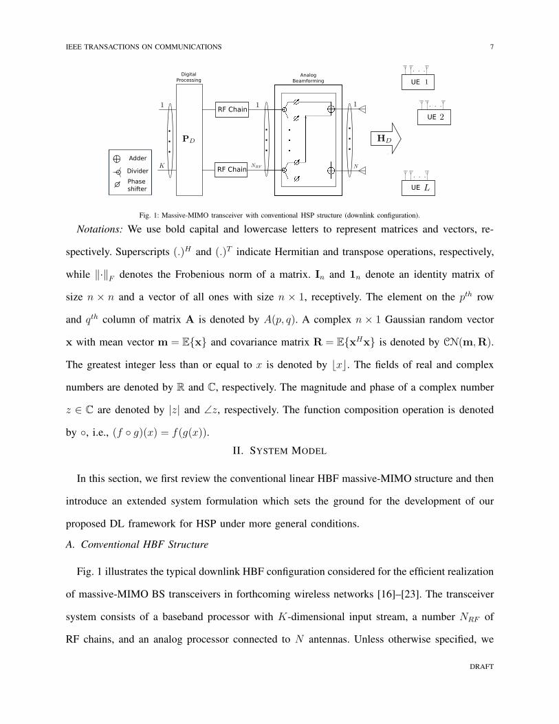
Fig. 1: Massive-MIMO transceiver with conventional HSP structure (downlink configuration).
Notations: We use bold capital and lowercase letters to represent matrices and vectors, re-
spectively. Superscripts (.)H and (.)T indicate Hermitian and transpose operations, respectively,
while ‖·‖F denotes the Frobenious norm of a matrix. In and 1n denote an identity matrix of
size n × n and a vector of all ones with size n × 1, receptively. The element on the pth row
and qth column of matrix A is denoted by A(p, q). A complex n × 1 Gaussian random vector
x with mean vector m = Ex and covariance matrix R = ExHx is denoted by CN(m,R).
The greatest integer less than or equal to x is denoted by ⌊x⌋. The fields of real and complex
numbers are denoted by R and C, respectively. The magnitude and phase of a complex number
z ∈ C are denoted by |z| and ∠z, respectively. The function composition operation is denoted
by , i.e., (f g)(x) = f(g(x)).
II. SYSTEM MODEL
In this section, we first review the conventional linear HBF massive-MIMO structure and then
introduce an extended system formulation which sets the ground for the development of our
proposed DL framework for HSP under more general conditions.
A. Conventional HBF Structure
Fig. 1 illustrates the typical downlink HBF configuration considered for the efficient realization
of massive-MIMO BS transceivers in forthcoming wireless networks [16]–[23]. The transceiver
system consists of a baseband processor with K-dimensional input stream, a number NRF of
RF chains, and an analog processor connected to N antennas. Unless otherwise specified, we
DRAFT

8 IEEE TRANSACTIONS ON COMMUNICATIONS
consider a multi-user scenario wherein the BS transceiver provides services to L ≤ K user
equipments (UE), each being allocated a fixed subset of the available data streams. For simplicity,
we assume that the lth UE is equipped with Ml antennas and the same number of RF chains,
so that it is capable of FD processing, as our main focus lies on the design and realization of
HSP-based massive-MIMO transceivers at the BS. In the sequel, we let M =∑L
l=1Ml denote
the total number of antenna elements employed by the UEs. While Fig. 1 focuses on dowlink
transmission for simplicity, we herein consider both downlink and uplink connections, where the
BS antennas are used for transmitting to and receiving from the UEs, respectively. Below, we
further expand the corresponding signal models.
Downlink: The signal vector transmitted by the BS over one symbol duration Ts, denoted as
x ∈ CN , can be expressed as
x =√ρPAPDs, (1)
where s = [s1, s2, ..., sK ]T ∈ A K is the input symbol vector with zero-mean random information
symbols sk taken from a discrete constellation A ⊂ C (e.g., M-QAM or M-PSK), normalized
such that EssH = IK , while matrices PD ∈ CNRF×K and PA ∈ UN×NRF represent the digital
and analog precoders, respectively, where U = z ∈ C : |z| = 1. For normalization purposes,
it is assumed that ‖PAPD‖2F = 1, so that ρ is the average transmit power.
The received signals at the UEs are represented by a concatenated signal vector y ∈ CM
which can be written as
y = HDx+ n, (2)
where HD ∈ CM×N is a zero-mean random channel matrix representing flat fading transmission
between the BS and the UE antennas, normalized such that E‖H‖2F = NM without loss of
generality, and n ∼ CN(0, IM) is an additive noise vector of size M . Each UE applies optimal
FD linear processing on its received signal prior to the decoding stage. The linear processing
performed by the multiple UEs is expressed as
s = Cy, (3)
DRAFT
IEEE TRANSACTIONS ON COMMUNICATIONS 9
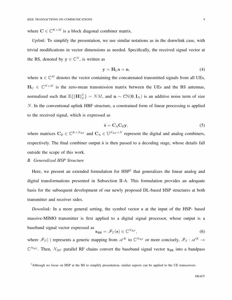
where C ∈ CK×M is a block diagonal combiner matrix.
Uplink: To simplify the presentation, we use similar notations as in the donwlink case, with
trivial modifications in vector dimensions as needed. Specifically, the received signal vector at
the BS, denoted by y ∈ CN , is written as
y = HUx+ n, (4)
where x ∈ CM denotes the vector containing the concatenated transmitted signals from all UEs,
HU ∈ CN×M is the zero-mean transmission matrix between the UEs and the BS antennas,
normalized such that E‖H‖2F = NM , and n ∼ CN(0, IN) is an additive noise term of size
N . In the conventional uplink HBF structure, a constrained form of linear processing is applied
to the received signal, which is expressed as
s = CACDy, (5)
where matrices CD ∈ CK×NRF and CA ∈ U
NRF×N represent the digital and analog combiners,
respectively. The final combiner output s is then passed to a decoding stage, whose details fall
outside the scope of this work.
B. Generalized HSP Structure
Here, we present an extended formulation for HSP2 that generalizes the linear analog and
digital transformations presented in Subsection II-A. This formulation provides an adequate
basis for the subsequent development of our newly proposed DL-based HSP structures at both
transmitter and receiver sides.
Downlink: In a more general setting, the symbol vector s at the input of the HSP- based
massive-MIMO transmitter is first applied to a digital signal processor, whose output is a
baseband signal vector expressed asxBB = FT (s) ∈ C
NRF , (6)
where FT (·) represents a generic mapping from A K to CNRF or more concisely, FT : A K →
CNRF . Then, NRF parallel RF chains convert the baseband signal vector xBB into a bandpass
2Although we focus on HSP at the BS to simplify presentation, similar aspects can be applied to the UE transceivers.
DRAFT
10 IEEE TRANSACTIONS ON COMMUNICATIONS
modulated RF signal vector xRF. The latter is next input to the analog signal processing network
whose output is the transmit signal vector, which is expressed as
x =√ρGT (xRF) ∈ C
N , (7)
where GT : A NRF → CN is the corresponding mapping. The received signal at the UE is given
by (2) and, in the case of FD linear combining, the demodulated symbols are obtained as in (3).
We emphasize that in the above formulation, the mappings FT and GT are no longer limited
to the class of linear transformations and could exhibit non-linear features, which is prerequisite
for the consideration of DNNs.
Uplink: The received signal from the large scale antenna array at the BS, which is given by
(4), first goes through the analog signal processing network, as represented by
xRF = GR(y) ∈ CNRF , (8)
where GR : A N → CNRF is the corresponding mapping. Then, NRF parallel RF chains convert
the RF signal vector xRF into a digital signal vector xBB which is subsequently passed through
a baseband processor, represented by
s = FR(xBB) ∈ CK , (9)
where FR : A NRF → CK is the corresponding mapping. Here again, we envisage a general
configuration where the mappings GR and FR could be non-linear.
III. ANALOG (RF) DEEP NEURAL NETWORKS
In this section, we present a novel ADNN structure for efficient implementation of DNNs
directly in the analog domain. We start by introducing terminology for DNN architecture and
training that will serve as basis in subsequent developments. We then present the linear and non-
linear RF modules which are required to carry out the necessary operations in DNNs. Finally
we present the proposed ADNN structure.
A. Deep Neural Networks
We consider complex-valued DNNs since in communication systems, complex numbers or
vectors are used for the representation of the transmitted and received bandpass signals. The
DRAFT
IEEE TRANSACTIONS ON COMMUNICATIONS 11
mathematical expression of a complex-valued multi-layer perceptron (MLP), or artificial neural
network, with one hidden layer, d neurons and a linear layer at its output, is given by:
Γ(x; θ) = Wψd(A (x)), (10)
where x ∈ Cn is the input vector, A (x) : Cn → Cd is an affine transformation, ψd is a non-
linear activation function and W ∈ Cm×d is the weight matrix of the output layer. Specifically,
A (x) = Ax + b where A ∈ Cd×n, b ∈ Cd are the weight matrix and bias vector of the
hidden layer, respectively. Moreover, for a given scalar activation function ψ : C → C, the
element-wise activation function ψd : Cd → Cd is defined as ψd(ξ) = [ψ(ξ1), ψ(ξ2), . . . , ψ(ξd)]
T .
where ξ ∈ Cd. Consequently, the set of parameters characterizing the MLP can be written as
θ = W,A,b. A common practice for simplifying the implementation of DNN algorithms
is to remove the bias term by adding an additional unit element to x and a column to A.
Consequently, by defining Ab = [A,b] and xb = [x, 1]T , we can rewrite (10) as:
Γ(x; θ) = Wψd(Abxb). (11)
To simplify the presentation, we focus on feed-forward DNN constructed from MLP with
multiple hidden layers, but extensions to other types of networks are possible. Let us consider
a DNN comprised of L ∈ N hidden layers indexed by l ∈ 1, 2, . . . , L, nl ∈ N neurons at the
l-th hidden layer, and one output layer indexed by l = L + 1, with input vector x ∈ CN0 and
output vector y ∈ CnL+1 . The mathematical representation of such DNN can be written as
y = Ω(x; θ) = (AL+1 ψnL AL · · · ψn1 A1)(x) (12)
where Al : Cnl−1 → Cnl is the affine transformation used at the l-th layer, i.e., Al(x) =
Alx + bl, with Al ∈ Cnl×nl−1 , bl ∈ Cnl representing the weights and biases of the l-th
layer. The ordered set of all parameters characterizing the DNN in (12) can be written as
θ = A1,b1,A2,b2, . . . ,AL+1,bL+1.
In practice, the network parameters in θ are tuned by training the DNN on a given dataset of
size ND, represented here by D = (x(i),y(i))ND
i=1 where, y(i) is the desired output for given
input vector x(i). In batch learning, the data set is partitioned into NB mini-batches Bj such that
DRAFT
12 IEEE TRANSACTIONS ON COMMUNICATIONS
D = ∪NB
i=jBj where each mini-batch is comprised of ND/NB distinct samples drawn from the
dataset. The network parameters are randomly initialized and subsequently adjusted by means
of an iterative process in two-steps: 1) the output of the network is first calculated for each
mini-batch (forward propagation), and a loss value is obtained using a cost function based on
the error between the actual outputs of the DNN and the desired outputs; 2) the parameters are
updated based on the gradient of the cost function with respect to each element of θ (backward
propagation). An epoch consists of updating the network parameter θ through forward and
backpropagation for all NB mini-batches. The training process is stopped after a number of
epochs which is determined based on a pre-selected accuracy measure.
B. Linear RF Modules
As discussed above, two different types of operations are required for calculating the output of
each DNN layer, i.e., for the l-th layer, a linear transformation Al and an elementwise non-linear
function ψnl. Let us first focus on the implementation of the linear transformation, which is not
an immediate task when using phase-shifters and power-combiners/dividers in RF domain. In
fact, most of the literature on hybrid beamforming is dedicated to this issue, and especially the
non-convexity of design problems involving transformation matrices with unit-modulus entries.
Motivated by hybrid designs in [13]–[15], we present below a first proposition which paves the
way for developing an analog structure consisting of phase-shifters and power-combiners/dividers
that can perform an arbitrary linear transformation.
Theorem 1: Any given complex matrix A ∈ Cl×n can be written as a scaled sum of two
matrices R(1),R(2) ∈ Ul×m, with unit-modulus entries, i.e.,
A = c(R(1) +R(2)), (13)
for some positive constant c ≥ 12‖vec(A)‖∞.
Proof: It is sufficient to show that for all p = 1, 2, ..., l and q = 1, 2, ..., n, we have
A(p, q) = c(
R(1)(p, q) +R(2)(p, q))
. (14)
DRAFT

IEEE TRANSACTIONS ON COMMUNICATIONS 13
Since R(1),R(2) ∈ UNR×K , the above equation can be further written as
A(p, q) = c(
ejθ(1)p,q + ejθ
(2)p,q)
, (15)
where ejθ(1)p,q and ejθ
(2)p,q represent the entries on the pth row and qth column of R(1) and R(2),
respectively. Since 2c is greater than the absolute value of all the entries of A, from Theorem 1
in [13], there exist non-unique θ(1)p,q and θ
(2)p,q such that (15) holds which proves the theorem.
Note that for a given matrix A, the matrices R(1) and R(2) such that A = c(R(1) + R(2))
holds are non-unique; below, we present a simple way to construct R(1), R(2). By expressing
the elements of A in polar form as A(p, q) = |Ap,q| exp(jϑp,q), we first compute
c =1
2maxp,q
|Ap,q|. (16)
We then calculate the entries of R(1) and R(2) as
R(1)(p, q) = ej(
ϑp,q+cos−1(|Ap,q|
2c))
(17a)
R(2)(p, q) = ej(
ϑp,q−cos−1(|Ap,q|
2c))
. (17b)
By simple mathematical manipulations one can easily verify the validity of the presented solu-
tions in (16) and (17) (see also [15]).
C. Nonlinear RF Modules
Next, we discuss possible structures for the realization of non-linear activation functions in
the analog domain with common RF modules.
In [43], it is shown that an arbitrarily wide MLP with one hidden layer is a universal approx-
imator due to the presence of the non-linear activation function. DNNs inherit this property and
different conditions for the activation functions have been presented under which the universality
of DNNs is satisfied [43]–[47]. In [43], the required conditions for the activation functions
ψ : R → R are given as being continuous, bounded and non-constant, while these conditions
DRAFT
14 IEEE TRANSACTIONS ON COMMUNICATIONS
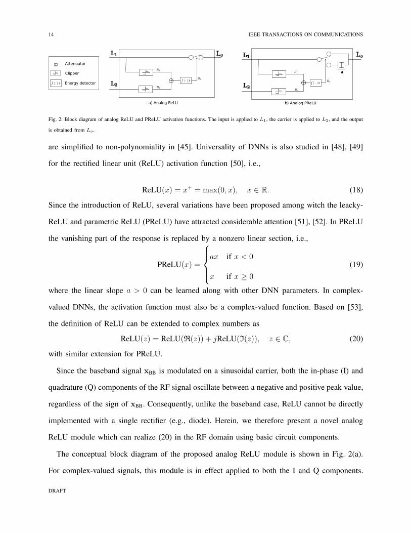
b) Analog PReLUa) Analog ReLU
aaa
Attenuator
Clipper
Energy detector<>
<> <>
Fig. 2: Block diagram of analog ReLU and PReLU activation functions. The input is applied to L1, the carrier is applied to L2, and the output
is obtained from Lo.
are simplified to non-polynomiality in [45]. Universality of DNNs is also studied in [48], [49]
for the rectified linear unit (ReLU) activation function [50], i.e.,
ReLU(x) = x+ = max(0, x), x ∈ R. (18)
Since the introduction of ReLU, several variations have been proposed among witch the leacky-
ReLU and parametric ReLU (PReLU) have attracted considerable attention [51], [52]. In PReLU
the vanishing part of the response is replaced by a nonzero linear section, i.e.,
PReLU(x) =
ax if x < 0
x if x ≥ 0
(19)
where the linear slope a > 0 can be learned along with other DNN parameters. In complex-
valued DNNs, the activation function must also be a complex-valued function. Based on [53],
the definition of ReLU can be extended to complex numbers as
ReLU(z) = ReLU(R(z)) + jReLU(I(z)), z ∈ C, (20)
with similar extension for PReLU.
Since the baseband signal xBB is modulated on a sinusoidal carrier, both the in-phase (I) and
quadrature (Q) components of the RF signal oscillate between a negative and positive peak value,
regardless of the sign of xBB. Consequently, unlike the baseband case, ReLU cannot be directly
implemented with a single rectifier (e.g., diode). Herein, we therefore present a novel analog
ReLU module which can realize (20) in the RF domain using basic circuit components.
The conceptual block diagram of the proposed analog ReLU module is shown in Fig. 2(a).
For complex-valued signals, this module is in effect applied to both the I and Q components.
DRAFT

IEEE TRANSACTIONS ON COMMUNICATIONS 15
The modulated signal is fed to L1 and the carrier is fed to L2 as a reference. The output Lo is
equal to the input signal L1 when the baseband signal is positive and zero otherwise. Indeed,
when the modulated signal L1 and the carrier L2 are in phase, corresponding to a positive
value of the baseband component, B1 and B2 are equal and the energy of their sum is non-zero.
Consequently, the output of the energy detector B3 = 1 which can be used to activate (i.e., close)
the switch. When the modulated signal L1 and the carrier L2 are out of phase (corresponding to
a negative value of the baseband component), we have B2 = −B1. Consequently, the energy of
their sum is zero and the output of energy detector B3 = 0, which opens the switch. Similarly, an
analog PReLU module can be designed as shown in Fig. 2(b) where the attenuator is a passive
component which is designed based on the learned value of a in (19).
D. Analog Deep Neural Network (ADNN)
The RF modules conceived in the previous two subsections can now be used to achieve our
main objective, which is to design an analog DNN structure, i.e. ADNN, such that
GT (xRF) = ΩT (xRF; θAT )
GR(y) = ΩR(y; θAR),
(21)
where ΩT () and ΩR() represent DNNs with respective parameter set θAT and θA
R. As discussed
in Subsection III-A, DNNs are formed by concatenating several MLPs. Consequently, we first
focus on the RF implementation of an MLP with single hidden layer in (11). For developing the
ADNN, we consider commonly used RF components in existing HSP, i.e., phase-shifters, and
power-dividers (which also work as combiners), along with the simple analog ReLU or PReLuU
modules introduced previously.
Theorem 2: A given MLP Γ(x; θ) with one hidden layer and non-linear activation function
ψd() (either ReLU or PReLU) can be realized by the RF structure shown in Fig. 3.
Proof: As discussed earlier an MPL is defined by matrices Ab and W which are used to
calculate Γ(x; θ) = Wψd(Abxb) where here, ψd(x) = ReLU(x) or PReLU(x). Using Theorem
DRAFT

16 IEEE TRANSACTIONS ON COMMUNICATIONS
Adder
Devider
PS
NLAF
Fig. 3: Analog MLP (NLAF = non-linear activation function, i.e. ReLU or PReLU).
1, there exist matrices R(1)Ab
, R(2)Ab
, R(1)W
and R(2)W
with constant-modulus entries, and positive
scalars cA, cW , such thatAb = cA(R
(1)Ab
+R(2)Ab) (22a)
W = cW (R(1)W
+R(2)W). (22b)
As can be seen from Fig. 3, xb fist goes through dividers which feed the analog subnetowrks R(1)Ab
,
R(2)Ab
, whose output are finally combined to produce vector r. Since we operate in the analog
domain, the power of the signal is split between each branch, so that only xb√2
is effectively
applied on each branch; similar, a factor of 1√2
must be include in the ouput of the combiner
to account for properties of the corresponding S-matrix [54]. Consequently, the vector of input
signals to the ReLUs can be written as
r =1√2(R
(1)Ab
xb√2+R
(2)Ab
xb√2). (23)
By substituting (22a) in (23), we arrive at
r =1
cAAbxb. (24)
After passing through the ReLU and performing similar steps as above steps for W, the output
of the analog MLP can be written as
Γ(x; θ) =1
cAcWWψd(Abxb) = Wψd(Ab
1
cAcWxb), (25)
DRAFT
IEEE TRANSACTIONS ON COMMUNICATIONS 17
where the second equality is due to the positive homogeneity of ReLU i.e., cReLU(x) =
ReLU(cx) for any positive c (c ∈ R+).
Corollary 1: Any given DNN Ω(x; θ) (12) can be realized in the RF domain by concatenating
several analog MLPs, as presented in Theorem 2.
IV. DEEP LEARNING FRAMEWORK FOR HSP
In this section, by taking advantage of the proposed ADNN structure, we present a general
DL framework for HSP which enables hybrid systems to exhibit similar performance as FD
systems with limited number of RF chains. These results are in contrast with conventional
hybrid systems where, due to non-convex constraints imposed on the RF beamfomer, degraded
performance must be accepted for reducing the number of RF chains. Moreover, our approach
enables further improvements over existing DNN-based HSP designs by incorporating ADNNs.
In the existing DNN-based hybrid designs, deep learning is used for designing the analog and
digital beamformers which face the same limitations as the conventional hybrid design, where
the minimum number of required RF chains is equal to the number of symbols streams. The
proposed HDNN, however, is not bound to this constraint and as will be shown for selected
cases, the number of RF chains can be further reduced significantly while maintaining the same
performance as the FD systems.
A. Proposed DL Framework for HSP
Downlink: Let us consider the downlink signal model introduced in Section II-B for the
generalized HSP structure. In the proposed HDNN framework, the non-linear digital processor
in (6) indeed corresponds to a first DNN, whose output is the baseband signal vector xBB i.e.,
FT (s) = ΩDT (s; θ
DT ), (26)
where θDT is the parameter set of this digital DNN. The baseband output of this DNN is then
converted to the RF domain where it is represented by xRF. Subsequently, the non-linear operator
DRAFT

18 IEEE TRANSACTIONS ON COMMUNICATIONS
Fig. 4: HDNN-based massive-MIMO transceiver.
in (7) is realized by means of a second ADNN structure, whose output (up to a scale factor) is
the desired transmit signal vector x, i.e.,
GT (xRF) = ΩAT (xRF; θ
AT ), (27)
where θAT is the parameter set of the ADNN.
To simplify the training process, we can consider the ADNN as additional layers to the digital
DNN, which brings us to
x = ΩAT
(
(
ΩDT (s; θ
DT )
)
; θAT
)
. (28)
From (12) and (10), we can write the above equation as
x = ΩHT (s; θT ), (29)
where θT = θAT , θ
DT is the composite parameter set of the resulting downlink HDNN..
Uplink: In this case, the non-linear digital processor in (8) corresponds to a first ADNN,
whose output is the RF signal vector xRF, i.e.,
GR(y) = ΩAR(y; θ
AR), (30)
where θAT is the parameter set of the ADNN. The RF output of this ADNN is then converted
to the baseband where it is represented by xBB. Subsequently, the non-linear operator in (9) is
realized by means of a digital DNN to produce the desired output vector s, i.e.,
FR(xBB) = ΩDR(xBB; θ
DR), (31)
DRAFT
IEEE TRANSACTIONS ON COMMUNICATIONS 19
where θAT is the parameter set of the DNN. Hence, proceeding as in the downlink case, we can
writes = ΩH
R (y; θR) = ΩAR
(
(
ΩDR (y; θ
DR)
)
; θAR
)
, (32)
where θR is the parameter set of the resulting uplink HDNN.
The proposed HDNN architecture is depicted in Fig. 4 where the forward propagation is shown
for both downlink and uplink scenarios. Here we considered regular DNNs, however, different
network structures, and DL techniques such as CNNs, RNNs, etc., can be indeed used in the
proposed framework. Since it is desirable to employ as few RF chains as possible, depending on
the specific task the HDNN may suffer from a bottle necking effect in the flow of information
from the digital DNN to the ADNN and vice versa. In theory, this problem can be partly mitigated
by increasing the width and depth of the ADNN or the digital DNN, as it has been shown that
deep and wide neural networks are universal approximators [43]–[49].
Conventional FD beamforming schemes are linear operations which are continuous functions
and thus can be generated by the proposed structure. Moreover, although the universality of
DNNs is only shown for continuous functions, the so-called expressive power of the DNNs
[43]–[49] enables them to successfully approximate a variety of functions which to our benefit,
can be leveraged to realize existing communication techniques within the hybrid DNN-based
systems.
B. DL-based Transceiver Design
In the following, we briefly discuss how the proposed framework can be used for HSP-based
massive-MIMO transceiver design. For the sake of brevity, we only discuss the downlink problem
formulation but the uplink problem can be also formulated in a similar way.
The HDNN can be trained to learn an arbitrary transmission scheme, as defined by the
mappings FT (·) and GT (·) in (6) and (7). This can be done by training the HDNN using
the following loss function,
L(θT ) =∥
∥ΩHT (s; θT )− GT FT (s)
∥
∥
2. (33)
DRAFT

20 IEEE TRANSACTIONS ON COMMUNICATIONS
This approach can be applied in principal to a variety of non-linear beamforming technique
such as vector perturbation [55], Tomlinson-Harashima precoding [56], [57], robust beamformer
design under imperfect CSI [21], and space-time coding [58]. In the next section, we design
and train HDNNs with FT (s) selected as the eigen-mode beamforming for both uplink and
downlink.
When the HDNN is trained using (33), the output of the HDNN ideally appropriates the
selected transmission scheme, i.e., FT (s). However, to take a step further and exploit the power
of machine learning paradigm, it is possible to let the transmitter learn the optimal transmission
scheme without explicitly specifying its structure a priori. To be more specific, the loss function
for training the HDNN can be a performance measure of the overall communication link,
i.e., taking the transmitter and receiver into account, as well as other constraints and system
requirements. Depending on the setup, constraint and requirements of the system it is possible
to formulate various loss functions. For instance, in the case of a massive-MIMO BS with a single
UE, and assuming that the latter UE uses a fixed combiner matrix C known at the transmitter
side, the HDNN can be trained using,
L(θT ) =∥
∥CHD ΩHT (s; θT )− s
∥
∥
2. (34)
For a multi-user scenario, the signal-to-interference-plus-noise (SINR) can be used instead of the
symbol error used above. Furthermore, additional constraints can be considered such as imperfect
CSI with norm-bounded error to design robust beamformers.
For sake of completeness, we also mention other machine learning techniques that can be used
within the proposed HDNN framework. Since in mobile and cellular communication systems,
CSI changes rapidly, efficiency and computational complexity are important issues. Consequently,
transfer learning techniques can be leveraged to facilitate the training process [59]. Moreover,
since cloud-ran is highly anticipated in B5G and 6G systems, distributed learning techniques
(e.g. federated learning and split learning) can be used in designing and training of HDNNs [60].
Ultimately, the proposed framework could be used in a reinforcement learning (RL) setup to
DRAFT
IEEE TRANSACTIONS ON COMMUNICATIONS 21
train an end-to-end communication system where channel estimation, beamforming, modulation,
etc., are all performed naively and directly via RL.
V. SUPERVISED LEARNING-BASED HBF WITH FD PERFORMANCE
In this section, to illustrate the potential advantages of the proposed DL framework for HSP,
we apply it to design supervised learning-based hybrid beamformers that achieve the performance
of FD beamforming with limited number of RF chains. We focus on the single user although
extension to multi-user is possible.
A. Uplink and Downlink Beamforming with NRF ≥ K
As discussed above, using the proposed framework, it is possible to closely approximate any
mapping form symbol vector s to the desired transmitted signal x. Consequently, we can use
supervised learning to train the DNN such that the hybrid system generates the output of the
FD beamforming with limited RF chains.
In the downlink, the optimal eigen-mode precoding is obtained by solving the following
problem:maxP
log2 det(IN +HDPPHHHD ), (35a)
s.t. Tr(PPH) ≤ 1. (35b)
The solution to the above problem is given by P = VDΥD, where the diagonal weight matrix
ΥD is calculated via water filling [6] and VD is a unitary matrix obtained from the singular
value decomposition of the channel matrix, represented in standard form as, HD = UDΣDVDH .
Thus, the desired output of the HDNN for symbol vector s is given by Ps and using (29), we
wish to find θT such that ΩHT (s; θT ) = Ps. We use an HDNN where the digital DNN has
LD = 5 hidden layers of size Kc1 and the ADNN has LA = 1 hidden layer of size Nc2. These
hyperparameters (which control the depth of the network and width of the hidden layers) may
vary based on the number of antennas and the number of RF chains and can be obtained by
cross referencing.
DRAFT

22 IEEE TRANSACTIONS ON COMMUNICATIONS
For each channel instance HD, the network is trained by generating random symbol vectors
and their corresponding desired transmitted signal. The network is then trained for the dataset
DH = (s(i),Ps(i))ND
i=1. Since the DNNs must is trained for regression, selecting the right loss
function is crucial, particularly, because in mmWave beamforming, a slight deviation can cause
huge performance degradation. From an optimization perspective, the ℓ1 norm results in a more
sparse error vector which is more favourable for our purpose compared to ℓ2 norm. Consequently,
we propose to the mean absolute error loss function which can be expressed as
L(θ) =1
ND
∑
s∈Bj
|ΩHT (s; θT )−Ps|, (36)
for the mini-batch Bj . Finally, using an optimization method such as Adaptive moment estimation
(Adam) the weights and biases of the network are updated during the backpropagation phase.
For uplink beamfomer (combiner), a similar network structure with the same hyperparameters
as the downlink case can be used as shown in Fig. 4. The optimal FD combiner can be obtained
from
maxC
log2 det(
IK + ρ(CCH)−1CHUHHU CH
)
. (37)
By writing the singular value decomposition of the uplink channel as HU = UUΣUVUH ,
we have, CH = UaU , where UU = [Ua
U ,UUb] and UU
a contains the first K columns of
UU , corresponding to the K dominant singular values. Training the DNN for uplink is not
as straightforward as for the downlink because the received signal is dominated by noise.
Consequently, we let
y = ρz+ n, (38)
where z ∼ CN(0, IN) is a Gaussian random vector and we want to find θR such that ΩHR (y; θR) =
Cy, i.e., the network is trained for the dataset DH = (y(i),Cy(i))ND
i=1. The same loss function
and optimizer as in the downlink can be used for learning the network parameter.
B. Downlink Beamforming with NRF < K
To illustrate the potential of the proposed framework, in this subsection we present a hybrid
precoder which can achieve the same performance as the FD beamforming with less than K RF
DRAFT
IEEE TRANSACTIONS ON COMMUNICATIONS 23
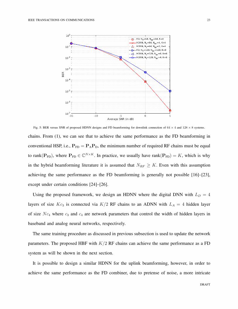
Fig. 5: BER versus SNR of proposed HDNN designs and FD beamforming for downlink connection of 64× 4 and 128 × 8 systems.
chains. From (1), we can see that to achieve the same performance as the FD beamforming in
conventional HSP, i.e., PFD = PAPD, the minimum number of required RF chains must be equal
to rank(PFD), where PFD ∈ CN×K . In practice, we usually have rank(PFD) = K, which is why
in the hybrid beamforming literature it is assumed that NRF ≥ K. Even with this assumption
achieving the same performance as the FD beamforming is generally not possible [16]–[23],
except under certain conditions [24]–[26].
Using the proposed framework, we design an HDNN where the digital DNN with LD = 4
layers of size Kc3 is connected via K/2 RF chains to an ADNN with LA = 4 hidden layer
of size Nc4 where c3 and c4 are network parameters that control the width of hidden layers in
baseband and analog neural networks, respectively.
The same training procedure as discussed in previous subsection is used to update the network
parameters. The proposed HBF with K/2 RF chains can achieve the same performance as a FD
system as will be shown in the next section.
It is possible to design a similar HDNN for the uplink beamforming, however, in order to
achieve the same performance as the FD combiner, due to pretense of noise, a more intricate
DRAFT

24 IEEE TRANSACTIONS ON COMMUNICATIONS
Fig. 6: BER versus SNR of proposed HDNN designs and FD beamforming for uplink connection of 64× 4 and 128× 8 systems.
DNN architecture and training process is required which remains a topic for future studies.
VI. SIMULATION RESULTS
In this section, simulation results are presented to illustrate the merits of the proposed HDNN
in section V, comparison with FD beamforming, as well as benchmark hybrid designs from the
literature are included.
A. Methodology
We use the following mmWave massive-MIMO channel model [11], [15],
H =
√
NM
NcNray
Nc∑
i=1
Nray∑
j=1
αijar(θrij)at(θ
tij)
H, (39)
where Nc = 5 is the number of clusters, and Nray = 10 is the number of rays in each cluster.
Similar to [11], [15], the path gains are independently generated as αij ∼ CN(0, 1). The transmit
and receive antenna responses are denoted by ar(θrij) and at(θ
tij) respectively. For simplicity, a
uniform linear array of size N with half-wavelength spacing is employed, hence where,
a(φ) =1√N[1, ejπ sin(φ), . . . , ej(N−1)π sin(φ)]. (40)
DRAFT
IEEE TRANSACTIONS ON COMMUNICATIONS 25
-10 -5 0 5
SNR(dB)
5
10
15
20
25
30
35
40
Spe
ctra
l Effi
cien
cy (
bits
/Hz/
s)
FDHDNNSOHALTOMPMO
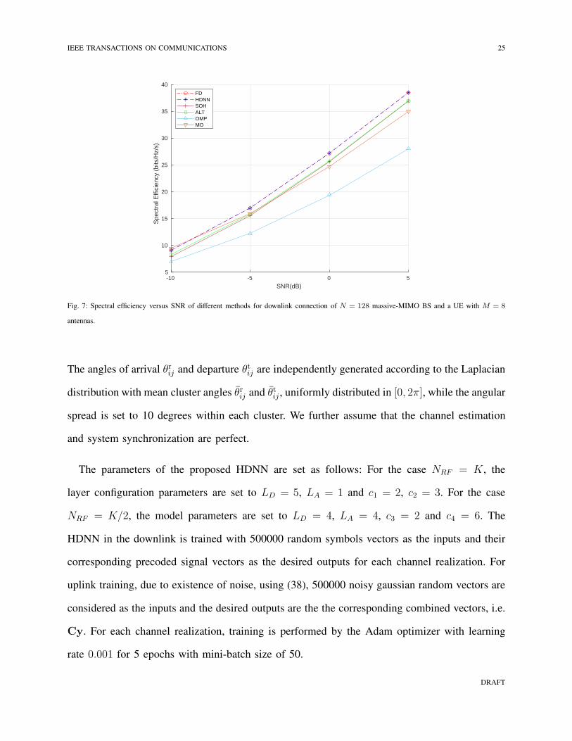
Fig. 7: Spectral efficiency versus SNR of different methods for downlink connection of N = 128 massive-MIMO BS and a UE with M = 8
antennas.
The angles of arrival θrij and departure θtij are independently generated according to the Laplacian
distribution with mean cluster angles θrij and θtij , uniformly distributed in [0, 2π], while the angular
spread is set to 10 degrees within each cluster. We further assume that the channel estimation
and system synchronization are perfect.
The parameters of the proposed HDNN are set as follows: For the case NRF = K, the
layer configuration parameters are set to LD = 5, LA = 1 and c1 = 2, c2 = 3. For the case
NRF = K/2, the model parameters are set to LD = 4, LA = 4, c3 = 2 and c4 = 6. The
HDNN in the downlink is trained with 500000 random symbols vectors as the inputs and their
corresponding precoded signal vectors as the desired outputs for each channel realization. For
uplink training, due to existence of noise, using (38), 500000 noisy gaussian random vectors are
considered as the inputs and the desired outputs are the the corresponding combined vectors, i.e.
Cy. For each channel realization, training is performed by the Adam optimizer with learning
rate 0.001 for 5 epochs with mini-batch size of 50.
DRAFT

26 IEEE TRANSACTIONS ON COMMUNICATIONS
-10 -5 0 5
SNR(dB)
5
10
15
20
25
30
35
40
Spe
ctra
l Effi
cien
cy (
bits
/Hz/
s)
FDHDNNSOHALTOMPMO
Fig. 8: Spectral efficiency versus SNR of different methods for uplink connection a UE with M = 8 and a massive-MIMO BS with N = 128.
B. Results and Discussion
We present the spectral efficiency (SE) and bit error rate (BER) performance of the proposed
HDNN design and the FD beamforming to confirm that the former achieves same performance as
the latter. However, since our design achieves the same performance as the FD beamforming, one
can find comparison between our design and existing hybrid designs directly in the corresponding
work, e.g., [11], [15], [18], [20], [35]–[38].
The BER performance versus signal-to-noise ratio (SNR) (which corresponds to parameter ρ
in (1) under normalization of the additive noise) for 64 × 4 and 128 × 8 point-to-point MIMO
setups are illustrated for uplink and downlink connections in Fig. 5 and 6, respectively. In both
cases the multi-antenna UE performs FD beamforming, 4-QAM constellation is used and the
number of transmitted symbols is equal to the number of UE’s antennas, i.e., K =M . It can be
observed that the proposed HDNN design matches the performance of the FD system with only
K RF chains. Moreover, for downlink beamforming, our proposed design in Subsection V-B
achieves the same performance with NRF = K/2 RF chains which to the best of our knowledge
DRAFT
IEEE TRANSACTIONS ON COMMUNICATIONS 27
-10 -5 0 5
SNR(dB)
0
5
10
15
20
25
30
35
Spe
ctra
l Effi
cien
cy (
bits
/Hz/
s)
FDHDNNSOHALTOMPMO
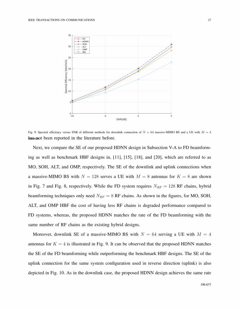
Fig. 9: Spectral efficiency versus SNR of different methods for downlink connection of N = 64 massive-MIMO BS and a UE with M = 4
antennas.has not been reported in the literature before.
Next, we compare the SE of our proposed HDNN design in Subsection V-A to FD beamform-
ing as well as benchmark HBF designs in, [11], [15], [18], and [20], which are referred to as
MO, SOH, ALT, and OMP, respectively. The SE of the downlink and uplink connections when
a massive-MIMO BS with N = 128 serves a UE with M = 8 antennas for K = 8 are shown
in Fig. 7 and Fig. 8, respectively. While the FD system requires NRF = 128 RF chains, hybrid
beamforming techniques only need NRF = 8 RF chains. As shown in the figures, for MO, SOH,
ALT, and OMP HBF the cost of having less RF chains is degraded performance compared to
FD systems, whereas, the proposed HDNN matches the rate of the FD beamforming with the
same number of RF chains as the existing hybrid designs.
Moreover, downlink SE of a massive-MIMO BS with N = 64 serving a UE with M = 4
antennas for K = 4 is illustrated in Fig. 9. It can be observed that the proposed HDNN matches
the SE of the FD beamforming while outperforming the benchmark HBF designs. The SE of the
uplink connection for the same system configuration used in reverse direction (uplink) is also
depicted in Fig. 10. As in the downlink case, the proposed HDNN design achieves the same rate
DRAFT

28 IEEE TRANSACTIONS ON COMMUNICATIONS
-10 -5 0 5
SNR(dB)
2
4
6
8
10
12
14
16
18
20
22
Spe
ctra
l Effi
cien
cy (
bits
/Hz/
s)
FDHDNNSOHALTOMPMO
Fig. 10: Spectral efficiency versus SNR of different methods for uplink connection a UE with M = 4 and a massive-MIMO BS with N = 64.
as the FD systems and has higher rate than the existing hybrid designs.
VII. CONCLUSION
In this paper, we presented a general DL framework for efficient design and implementation
of HSP in massive-MIMO systems. By exploiting the fact that any complex matrix can be
written as a scaled sum of two matrices with unit-modulus entries, we first presented a novel
ADNN which can be implemented with common RF. This structure was subsequently embedded
into an extended HDNN architecture to facilitate the implementation of mmWave massive-
MIMO systems and improving their performance. Since the proposed HDNN architecture enables
HSP-based massive-MIMO transceivers to approximate any desired transmitter and receiver
mapping with arbitrary precision, we were able to present a new HDNN-based beamformer
design that can achieve the same performance as FD beamforming, with reduced number of RF
chains. Simulation results were finally presented which confirmed that our design outperforms
benchmark hybrid design in the literature by achieving the same performance as the FD systems.
DRAFT
IEEE TRANSACTIONS ON COMMUNICATIONS 29
REFERENCES
[1] E. Telatar, “Capacity of multi-antenna gaussian channels,” Eur. Trans. Telecommun., vol. 10, no. 6, pp. 585–595, 1999.
[2] E. G. Larsson, O. Edfors, F. Tufvesson, and T. L. Marzetta, “Massive MIMO for next generation wireless systems,” IEEE
Commun. Mag., vol. 52, no. 2, pp. 186–195, Feb. 2014.
[3] F. Rusek, D. Persson, B. K. Lau, E. G. Larsson, T. L. Marzetta, O. Edfors, and F. Tufvesson, “Scaling up MIMO:
Opportunities and challenges with very large arrays,” IEEE Signal Process. Mag., vol. 30, no. 1, pp. 40–60, Jan. 2013.
[4] A. Schumacher, R. Merz, and A. Burg, “Adding indoor capacity without fiber backhaul: An mmWave bridge prototype,”
IEEE Commun. Mag., vol. 59, no. 4, pp. 110–115, 2021.
[5] Y. Xing, T. S. Rappaport, and A. Amitava, “Millimeter wave and sub-THz indoor radio propagation channel measurements,
models, and comparisons in an office environment,” IEEE Commun. Lett., pp. 1–1, 2021.
[6] E. Torkildson, U. Madhow, and M. Rodwell, “Indoor millimeter wave MIMO: Feasibility and performance,” IEEE Trans.
Wireless Commun., vol. 10, no. 12, pp. 4150–4160, Dec. 2011.
[7] R. C. Daniels and R. W. Heath, “60 GHz wireless communications: Emerging requirements and design recommendations,”
IEEE Trans. Veh. Technol., vol. 2, no. 3, pp. 41–50, Sept. 2007.
[8] S. Hur, T. Kim, D. J. Love, J. V. Krogmeier, T. A. Thomas, and A. Ghosh, “Millimeter wave beamforming for wireless
backhaul and access in small cell networks,” IEEE Trans. Commun., vol. 61, no. 10, pp. 4391–4403, Oct. 2013.
[9] A. Alkhateeb, J. Mo, N. Gonzalez-Prelcic, and R. W. Heath, “MIMO precoding and combining solutions for millimeter-
wave systems,” IEEE Commun. Mag., vol. 52, no. 12, pp. 122–131, Dec. 2014.
[10] Y. Lu and W. Zhang, “Hybrid precoding design achieving fully digital performance for millimeter wave communications,”
J. Commun. Inf. Netw., vol. 3, pp. 74–84, 12 2018.
[11] T. Lin, J. Cong, Y. Zhu, J. Zhang, and K. B. Letaief, “Hybrid beamforming for millimeter wave systems using the MMSE
criterion,” IEEE Trans. Commun., vol. 67, no. 5, pp. 3693–3708, 2019.
[12] B. Di, H. Zhang, L. Song, Y. Li, Z. Han, and H. V. Poor, “Hybrid beamforming for reconfigurable intelligent surface based
multi-user communications: Achievable rates with limited discrete phase shifts,” IEEE J. Select. Areas Commun., vol. 38,
no. 8, pp. 1809–1822, 2020.
[13] X. Zhang, A. F. Molisch, and S.-Y. Kung, “Variable-phase-shift-based RF-baseband codesign for MIMO antenna selection,”
IEEE Trans. Signal Process., vol. 53, no. 11, pp. 4091–4103, Nov. 2005.
[14] T. E. Bogale, L. B. Le, A. Haghighat, and L. Vandendorpe, “On the number of RF chains and phase shifters, and scheduling
design with hybrid analog digital beamforming,” IEEE Trans. Wireless Commun., vol. 15, no. 5, pp. 3311–3326, May 2016.
[15] F. Sohrabi and W. Yu, “Hybrid digital and analog beamforming design for large-scale antenna arrays,” IEEE J. Sel. Topics
Signal Process., vol. 10, no. 3, pp. 501–513, Apr. 2016.
[16] O. E. Ayach, S. Rajagopal, S. Abu-Surra, Z. Pi, and R. W. Heath, “Spatially sparse precoding in millimeter wave MIMO
systems,” IEEE Trans. Wireless Commun., vol. 13, no. 3, pp. 1499–1513, Mar. 2014.
[17] A. Alkhateeb and R. W. Heath, “Frequency selective hybrid precoding for limited feedback millimeter wave systems,”
IEEE Trans. Wireless Commun., vol. 64, no. 5, pp. 1801–1818, May 2016.
[18] X. Yu, J. C. Shen, J. Zhang, and K. B. Letaief, “Alternating minimization algorithms for hybrid precoding in millimeter
wave MIMO systems,” IEEE J. Sel. Topics Signal Process., vol. 10, no. 3, pp. 485–500, Apr. 2016.
[19] R. Mai, D. H. N. Nguyen, and T. Le-Ngoc, “MMSE hybrid precoder design for millimeter-wave massive MIMO systems,”
in Proc. IEEE Wireless Commun. Netw. Conf. (WCNC), Apr. 2016, pp. 1–6.
[20] D. H. N. Nguyen, L. B. Le, T. Le-Ngoc, and R. W. Heath, “Hybrid MMSE precoding and combining designs for mmWave
multiuser systems,” IEEE Access, vol. 5, pp. 19 167–19 181, 2017.
[21] A. Morsali and B. Champagne, “Robust hybrid analog/digital beamforming for uplink massive-MIMO with imperfect CSI,”
in Proc. IEEE Wireless Commun. Netw. Conf. (WCNC),, Apr. 2019, pp. 1–6.
[22] J. Li, L. Xiao, X. Xu, and S. Zhou, “Robust and low complexity hybrid beamforming for uplink multiuser mmWave MIMO
systems,” IEEE Commun. Lett., vol. 20, no. 6, pp. 1140–1143, June 2016.
[23] L. Jiang and H. Jafarkhani, “mmWave amplify-and-forward MIMO relay networks with hybrid precoding/combining
design,” IEEE Trans. Wireless Commun., vol. 19, no. 2, pp. 1333–1346, 2020.
[24] A. Morsali, A. Haghighat, and B. Champagne, “Realizing fully digital precoders in hybrid A/D architecture with minimum
number of RF chains,” IEEE Commun. Lett., vol. 21, no. 10, pp. 2310–2313, Oct. 2017.
[25] A. Morsali, S. Norouzi, and B. Champagne, “Single RF chain hybrid analog/digital beamforming for mmWave massive-
MIMO,” in IEEE global Conf. Signal Inf. Process. (GlobalSIP), Nov. 2019, pp. 1–5.
[26] A. Morsali and B. Champagne, “Achieving fully-digital performance by hybrid analog/digital beamforming in wide-band
massive-MIMO systems,” in IEEE Int. Conf. Acoust., Speech Signal Process. (ICASSP), May 2020, pp. 5125–5129.
[27] A. Morsali, A. Haghighat, and B. Champagne, “Generalized framework for hybrid analog/digital signal processing in
massive and ultra-massive-MIMO systems,” IEEE Access, vol. 8, pp. 100 262–100 279, 2020.
[28] F. Sohrabi and W. Yu, “Hybrid analog and digital beamforming for mmwave OFDM large-scale antenna arrays,” IEEE J.
Select. Areas Commun., vol. 35, no. 7, pp. 1432–1443, july 2017.
[29] F. Khalid, “Hybrid beamforming for millimeter wave massive multiuser MIMO systems using regularized channel
diagonalization,” IEEE Wireless Commun. Lett., vol. 8, no. 3, pp. 705–708, June 2019.
DRAFT
30 IEEE TRANSACTIONS ON COMMUNICATIONS
[30] M. M. Molu, P. Xiao, M. Khalily, K. Cumanan, L. Zhang, and R. Tafazolli, “Low-complexity and robust hybrid
beamforming design for multi-antenna communication systems,” IEEE Trans. Wireless Commun., vol. 17, no. 3, pp.
1445–1459, Mar. 2018.
[31] C. Ho, H. Cheng, and Y. Huang, “Hybrid precoding processor for millimeter wave MIMO communications,” IEEE Trans.
Circuits Syst. II, vol. 66, no. 12, pp. 1992–1996, 2019.
[32] B. Zhu, J. Wang, L. He, and J. Song, “Joint transceiver optimization for wireless communication PHY using neural
network,” IEEE J. Select. Areas Commun., vol. 37, no. 6, pp. 1364–1373, 2019.
[33] Z. Qin, H. Ye, G. Y. Li, and B. F. Juang, “Deep learning in physical layer communications,” IEEE Trans. Wireless Commun.,
vol. 26, no. 2, pp. 93–99, 2019.
[34] H. Huang, S. Guo, G. Gui, Z. Yang, J. Zhang, H. Sari, and F. Adachi, “Deep learning for physical-layer 5G wireless
techniques: Opportunities, challenges and solutions,” IEEE Trans. Wireless Commun., vol. 27, no. 1, pp. 214–222, 2020.
[35] A. Alkhateeb, S. Alex, P. Varkey, Y. Li, Q. Qu, and D. Tujkovic, “Deep learning coordinated beamforming for highly-mobile
millimeter wave systems,” IEEE Access, vol. 6, pp. 37 328–37 348, 2018.
[36] H. Huang, Y. Song, J. Yang, G. Gui, and F. Adachi, “Deep-learning-based millimeter-wave massive MIMO for hybrid
precoding,” IEEE Trans. Veh. Technol., vol. 68, no. 3, pp. 3027–3032, 2019.
[37] T. Lin and Y. Zhu, “Beamforming design for large-scale antenna arrays using deep learning,” IEEE Trans. Wireless
Commun., vol. 9, no. 1, pp. 103–107, 2020.
[38] L. Sung and D. Cho, “Multi-user hybrid beamforming system based on deep neural network in millimeter-wave
communication,” IEEE Access, vol. 8, pp. 91 616–91 623, 2020.
[39] A. M. Elbir, “CNN-based precoder and combiner design in mmwave MIMO systems,” IEEE Wireless Commun. Lett.,
vol. 23, no. 7, pp. 1240–1243, 2019.
[40] T. Peken, S. Adiga, R. Tandon, and T. Bose, “Deep learning for SVD and hybrid beamforming,” IEEE Trans. Wireless
Commun., vol. 19, no. 10, pp. 6621–6642, 2020.
[41] X. Bao, W. Feng, J. Zheng, and J. Li, “Deep CNN and equivalent channel based hybrid precoding for mmwave massive
MIMO systems,” IEEE Access, vol. 8, pp. 19 327–19 335, 2020.
[42] Z. Lu, H. Pu, F. Wang, Z. Hu, and L. Wang, “The expressive power of neural networks: A view from the width,” in Proc.
Adv. Neural Inf. Process. Syst (NeurIPS), vol. 30, Dec. 2017, pp. 6231–6239.
[43] K. Hornik, “Approximation capabilities of multilayer feedforward networks,” Neural Netw., vol. 4, p. 251–257, 1991.
[44] J. Park and I. W. Sandberg, “Universal approximation using radial-basis-function networks,” Neural Comput., vol. 3, p.
246–267, 1991.
[45] M. Lensho and V. Y. Lin, A. Pinkus, and S. Schocken, “Multilayer feedfor-ward networks with a nonpolynomial activation
function can approxi-mate any function,” Neural Netw., vol. 6, p. 861–876, 1993.
[46] G. Huang and a. C. S. L. Chen, “Universal approximation using incremental constructive feedforward networks with
random hidden nodes,” Trans. Neur. Netw., vol. 17, no. 4, p. 879–892, 2006.
[47] H. N. Mhaskar and T. Poggio, “Deep vs. shallow networks: An approximation theory perspective,” Analysis and
Applications, vol. 14, no. 06, pp. 829–848, 2016.
[48] B. Hanin, “Universal function approximation by deep neural nets with bounded width and ReLU activations,” Mathematics,
vol. 7, no. 10, p. 992, 2019.
[49] B. Hanin and M. Sellke, “Approximating continuous functions by ReLU nets of minimal width,” arXiv preprint
arXiv:1710.11278, 2017.
[50] V. Nair and G. E. Hinton, “Rectified linear units improve restricted boltzmann machines,” in Proc. Int. Conf. Mach. Learn.
(ICML), ser. ICML’10, June 2010, p. 807–814.
[51] A. Y. H. A. L. Maas and A. Y. Ng, “Rectifier nonlinearities improve neural network acoustic models,” in Proc. Int. Conf.
Mach. Learn. (ICML), ser. ICML’13, June 2013.
[52] S. R. K. He, X. Zhang and J. Sun, “Delving deep into rectifiers: Surpassing human-level performance on imagenet
classification,” in IEEE Int. Conf. Comput. Vision (ICCV), Dec. 2015, pp. 1026–1034.
[53] C. Trabelsi and O. Bilaniuk and D. Serdyuk and S. Subramanian and J. F. Santos and S. Mehri and N. Rostamzadeh and
Y. Bengio and C. Pal, “Deep complex networks,” ArXiv, vol. abs/1705.09792, 2018.
[54] D. M. Pozar, Microwave Engineering. John Wiley and Sons, 2005.
[55] B. M. Hochwald, C. B. Peel, and A. L. Swindlehurst, “A vector-perturbation technique for near-capacity multiantenna
multiuser communication-part II: perturbation,” vol. 53, no. 3, pp. 537–544, 2005.
[56] M. Tomlinson, “New automatic equaliser employing modulo arithmetic,” IET Electron. Lett., vol. 7.
[57] H. Harashima and H. Miyakawa, “Matched-transmission technique for channels with intersymbol interference,” IEEE
Trans. Commun., vol. 20, no. 4, pp. 774–780, 1972.
[58] A. Morsali, S. S. Hosseini, B. Champagne, and X. Chang, “Design criteria for omnidirectional STBC in massive MIMO
systems,” IEEE Wireless Commun. Lett., vol. 8, no. 5, pp. 1435–1439, Oct. 2019.
[59] Y. Yang, F. Gao, Z. Zhong, B. Ai, and A. Alkhateeb, “Deep transfer learning-based downlink channel prediction for fdd
massive mimo systems,” IEEE Trans. Commun., vol. 68, no. 12, pp. 7485–7497, 2020.
DRAFT

IEEE TRANSACTIONS ON COMMUNICATIONS 31
[60] K. J, H. B. McMahan, F. X. Yu, P. Richtarik, A. T. Suresh, and D. Bacon, “Federated learning: Strategies for improving
communication efficiency,” in NIPS Workshop on Private Multi-Party Machine Learning, 2016.
DRAFT