ieee transactions on dependable and secure … · transient pulse at the site of a particle strike...
TRANSCRIPT
Soft Error Rate Analysis forCombinational Logic Using an
Accurate Electrical Masking ModelFeng Wang, Student Member, IEEE, and Yuan Xie, Senior Member, IEEE
Abstract—Accurate electrical masking modeling represents a significant challenge in soft error rate analysis for combinational logic
circuits. In this paper, we use table lookup MOSFET models to accurately capture the nonlinear properties of submicron MOS
transistors. Based on these models, we propose and validate the transient pulse generation model and propagation model for soft error
rate analysis. The pulse generated by our pulse generation model matches well with that of HSPICE simulation, and the pulse
propagation model provides nearly one order of magnitude improvement in accuracy over the previous models. Using these two
models, we propose an accurate and efficient block-based soft error rate analysis method for combinational logic circuits.
Index Terms—Reliability, simulation, fault injection, combinational logic.
Ç
1 INTRODUCTION
SINGLE Event Upset (SEU) is a voltage transient caused byneutron or alpha particles from cosmic ray or package
materials [37]. The voltage transients may flip bits in memorycells or latches, causing soft errors. Soft errors in memory canbe corrected by Error Correcting Code (ECC) circuitry, andmany radiation harden techniques for memory cells orlatches have been proposed [37], [15]. However, voltagetransients caused by particle strikes can happen on any nodein combinational logic. This transient pulse can propagatethrough logic gates, and finally, be latched by a sequentialelement, resulting in a soft error [29]. Cheap solutions toreduce soft errors caused by transients generated in combina-tional logic are not well understood yet. Fast and accurateanalysis of soft error rate for combinational logic circuits is thefirst step toward the effort of finding efficient solutions [18].
There are three masking effects that can prevent atransient pulse in combinational logic from propagatingand being latched by a memory element: logical masking,electrical masking, and latch window masking [29]. Logicalmasking happens when one of the other inputs of a gate isin controlling state (e.g., 0 for a NAND gate) so that thetransient is blocked. Latch window masking means that thearrival transient pulse is outside of the latching window forthe sequential elements. These two masking effects havebeen well studied [15], [29], [32], [33], [10], [20]. Electricalmasking happens when the voltage transient resulting froma particle strike is attenuated by subsequent logic gatesbecause of the electrical property of logic gates [15].
Electrical masking plays an important role in soft errorrate estimation for combinational logic. For example, ourexperimental result shows that for a small circuit with logicdepth of five stages, ignoring electrical masking effect canoverestimate the SER by 138 percent. Many models for theelectrical masking effect have been proposed [24], [16], [6],[5], [29], [32], [33], [34], [7], [19]. However, these modelsintroduce large errors for the estimation of transient pulsepropagation, resulting in inaccurate soft error analysis forcombinational logic. Inaccuracy in transient pulsewidthestimation can lead to large error in the soft error rateanalysis [6]. For example, assuming that the transient pulseestimation error is 15 percent, for the same circuitmentioned afore, 52 percent error in the SER estimationcan be introduced.
In this paper, we propose and validate transient pulse
generation and transient pulse propagation models for accurateelectrical masking analysis. Based on these models, wepropose an accurate and fast block-based SER analysismethod for the combinational logic circuits.
The rest of the paper is organized as follows: Section 2reviews related work; Section 3 presents MOS transistormodeling; Section 4 provides the background on the softerror rate calculation and discusses the models of transientpulse generation and pulse propagation; Section 5 presentsour soft error rate estimation methods; and Section 6 showsexperimental results on the test circuits. Finally, theconclusions are provided in Section 7.
2 RELATED WORK
Early work in estimating SER in the combinational logiccircuits was based on the time-consuming Monte-CarloSimulations [13], [21]. Recently, many attempts have beenmade to estimate the SER of logic circuits quickly andaccurately [29], [32], [33], [34], [7], [26]. Fault simulationmethods [20] or BDD-based techniques [32] can be used to
IEEE TRANSACTIONS ON DEPENDABLE AND SECURE COMPUTING, VOL. 8, NO. 1, JANUARY-FEBRUARY 2011 137
. F. Wang is with Qualcomm Incorporated, WC-220K, 5828 Pacific CenterBlvd., San Diego, CA 92121. E-mail: [email protected].
. Y. Xie is with Pennsylvania State University, 354E Information ScienceTechnology Building, University Park, PA 16802.E-mail: [email protected].
Manuscript received 24 Sept. 2007; revised 31 Dec. 2008; accepted 21 Apr.2009; published online 22 July 2009.For information on obtaining reprints of this article, please send e-mail to:[email protected], and reference IEEECS Log Number TDSC-2007-09-0141.Digital Object Identifier no. 10.1109/TDSC.2009.29.
1545-5971/11/$26.00 � 2011 IEEE Published by the IEEE Computer Society

estimate the logic masking effect. Latch window maskingeffect is also modeled by Shivakumar et al. [29].
Various techniques [5], [24], [6], [5], [33], [34], [7], [29],[16], [6], [19], [36], [4], [27] have been proposed to capturethe electrical masking effect in SEU simulation. Thesetechniques at the circuit level and the logic level can becategorized into four major types.
1. Simple trapezoidal- or triangle-waveform-approxi-mation-based approaches [7], [32], [24], [4], [29]: Inthese approaches, the SEU-induced transients arecaptured by the simple parameters: the slope, themagnitude, and the width. These parameters of atransient pulse at the site of a particle strike areobtained by precharacterization of the library cells.For transient pulse propagations, empirical mathe-matical equations [24], [29], such as delay degrada-tion model, or transfer functions [32], are used topredict the transient responses of the gates. Transferfunctions of the gates are obtained via circuitsimulation with SPICE for different library cells.
2. Equivalent-inverter-based approaches [16], [5], [33]:In these approaches, the transistor-level models oflogic gates are reduced to equivalent inverters. Theeffective width of the single transistor is used toreplace series-connected transistors.
3. Simple RC-model-based approaches: Based uponlinear RC models of logic gates, the transientresponse can be computed using close-formedequations [6], [19], [36]. Dahlgren’s approach assignsa resistance to each transistor based on the width/length ratio and models transistors in series as theequivalent resistance.
4. Rao et al. [27] proposes a parametric waveformmodel based on the Weibull function.
However, these approaches are not sufficiently accurateto capture the electrical masking effect on the radiation-induced transients. Approaches belonging to category 1 arevery simple and fast, but these approaches cannot coverthe possible radiation-induced transient waveforms thatcan be generated due to particle strikes and cannot capturethe nonlinear gate transfer characteristics for SEU-inducedtransients [19]. Approaches of category 2 provide a goodestimation of propagation delay for full swing signals,but the predicted transient responses do not match wellwith SPICE simulations due to the errors in the currentestimation [22]. In addition, current-based simulationapproaches are relatively slow [22]. Approaches of type 3are simple, but they fail to account for the nonlinear gatetransfer characteristics for SEU-induced transients [19]. Intype 4, Rao et al.’s model [27] is simple and efficient, but itsapplication is limited because it fails to handle the swingsabove Vdd or below ground because it only matches thevalues of the pulse between ground and Vdd. Thus,accurately modeling the electrical masking effect forcombinational logic circuits remains a challenge.
Traditionally, the soft error rate analysis is performedusing path-based approach [29], [33], [34], [5], [6]. In thiswork, we use block-based approach, which has been widelyused in the statistical timing analysis [30], to achieve fastsoft error rate analysis. In the path-based approach, all
possible paths from the nodes in the netlist to the primaryoutputs are enumerated, and the number of the path is anexponential function of gates. Block-based approach hastwo-key advantages over the path-based approach: avoid-ing the recomputation by reusing the pulse estimationresult of the gate for all its fan-out nodes and lowcomputation complexity.
Our contributions in this paper distinguish itself in thefollowing aspects: 1) we propose a more accurate electricalmasking model that takes into account the nonlinearproperties of MOS transistors and covers all the possibletransient waveforms that can be generated due to particlestrikes and 2) we propose a fast block-based soft erroranalysis method for combinational logic that utilizes theaccurate electrical masking model.
3 DEVICE MODELING
In this section, we present two lookup-table-based devicemodels: one is the drain current model, and the other is thecapacitance model. These models effectively capture thenonlinear properties of the MOS transistors. Shima et al.[9] originally proposed the lookup-table-based drain cur-rent model for a single transistor in their device simulator.We extend their current model to series-connected transistors.We also model the parasitic capacitance using lookuptables. With lookup-table-based device models, arbitraryprecision in modeling the nonlinear devices can be achievedby simply adding more entries to the table. In addition tothe nonlinear properties of the MOS transistor, both thestacking effects of series-connected MOS transistors and theinput patterns [32] have significant impact on the accuracyof the transient error analysis. Both factors have been takeninto account in our transistor modeling.
3.1 MOS Transistor Drain Current Modeling
The analytic models [17], [28], [14] approximate the draincurrent as a simple quadratic function or linear function indifferent regions. They match I-V characteristics of CMOSgates at the high-current region very well [12]. However,the current at the linear region is typically underestimatedin these models and that current plays an important role inestimating the waveform of a transient pulse [12]. With areasonable number of the table entries in the drain currenttable, the model matches the I-V characteristics of the mostadvanced bulk CMOS model very well. Since drain current(Ids) is the function of the gate-source voltage (Vgs) and thedrain-source voltage (Vds), it can be obtained from theHSPICE simulation by sweeping Vds and Vgs.
Both the stacking effects of series-connected MOStransistors and the input patterns [32] have been taken intoaccount in our transistor modeling. Different input transi-tion patterns can result in different operation regiontransitions for each stacked transistor. Modeling the regionchanges in the stacking transistors complicates the transientpulse simulation. To address this effect, we model theseries-connected transistors as a single block, and applydifferent input transitions to the block and extract the draincurrent for that block. The drain current (Ids) is the functionof the number of series-connected transistors, the biasedvoltages, and the input transitions.
138 IEEE TRANSACTIONS ON DEPENDABLE AND SECURE COMPUTING, VOL. 8, NO. 1, JANUARY-FEBRUARY 2011
3.2 MOS Effective Capacitance Modeling
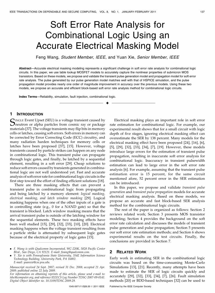
The transient response of a combinational logic gate issensitive to the effective capacitance of the logic gates.Although the pulse propagation delay of a single gate canbe estimated by using a single load capacitance withconstant value, which is commonly used in the static timinganalysis, the analysis of the transient response of thecombinational circuits requires a model to characterize thenonlinear property of capacitance. Fig. 1 shows nonlinearproperties of the gate to drain capacitance with differentinput and output voltage applied to an inverter. Thecapacitance of the transistors is the function of the gate-source voltage (Vgs) and the drain-source voltage (Vds).Therefore, accurate results cannot be obtained by using asingle constant capacitance model, since there are a varietyof different signal waveforms in the transient analysis.
In this study, similar to the transistor drain currentmodeling, we construct a lookup-table-based capacitancemodel by extracting the capacitance from HSPICE simula-tion, and sweeping the gate-source voltage (Vgs) anddrain-source voltage (Vds).
4 ELECTRICAL MASKING MODELING FOR
COMBINATIONAL LOGIC CIRCUITS
Our electrical masking model consists of the pulse generationand the pulse propagation model. In this section, we first reviewthe soft error analysis methods considering three maskingeffects. We then present the waveform approximationmethod for the transient pulse. Based on this approximationmethod, we present accurate models to estimate the transientpulse generation and attenuation using the table-basedtransistor models presented in Section 3.
4.1 Background
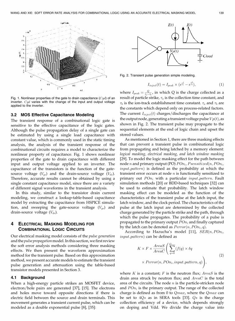
When a high-energy particle strikes an MOSFET device,electron/hole pairs are generated [37], [15]. The electronsand holes move toward opposite directions if there iselectric field between the source and drain terminals. Thismovement generates a transient current pulse, which can bemodeled as a double exponential pulse [8], [35]:
IinjectðtÞ ¼ Ipeak � ðe�t�a � e
�t�b Þ; ð1Þ
where Ipeak ¼ Q�a��b , in which Q is the charge collected as a
result of particle strike, �a is the collection time constant, and
�b is the ion-track establishment time constant. �a and �b are
the constants which depend only on process-related factors.
The current IinjectðtÞ charges/discharges the capacitance at
the output node, generating a transient voltage pulseV pðtÞ, as
shown in Fig. 2. The transient pulse may propagate to the
sequential elements at the end of logic chain and upset the
stored values.As mentioned in Section 1, there are three masking effects
that can prevent a transient pulse in combinational logicfrom propagating and being latched by a memory element:logical masking, electrical masking, and latch window masking[29]. To model the logic masking effect for the path betweennode n and primary output (PO) POni; Psensitizedðn; POni;input patternÞ is defined as the probability at which thetransient error occurs at node n is functionally sensitized toprimary out POni with a particular input pattern. Faultsimulation methods [20] or BDD-based techniques [32] canbe used to estimate that probability. The latch windowmasking effect can be modeled as the function of thecharacteristics of the transient pulse at the latch input, thelatch window, and the clock period. The characteristics of thepulse at the latch input are determined by the collectedcharge generated by the particle strike and the path, throughwhich the pulse propagates. The probability of a pulse ispropagated to the primary output POni and finally capturedby the latch can be denoted as Perrorðn; POni; qÞ.
According to Hazucha’s model [11], SERðn; POni;input patternÞ can be defined as
K � F � AreaSAreaC
XQmax
q¼0
ðfðqÞ � �q
� Perrorðn; POni; input pattern; qÞ!;
ð2Þ
where K is a constant; F is the neutron flux; AreaS is thedrain area struck by neutron flux; and AreaC is the totalarea of the circuits. The node n is the particle-stricken nodeand POni is the primary output. The range of the collectedcharge is defined as from 0 to Qmax, where the Qmax canbe set to 4Qs as in SERA tools [33]. Qs is the chargecollection efficiency of a device, which depends stronglyon doping and Vdd. We divide the charge value into
WANG AND XIE: SOFT ERROR RATE ANALYSIS FOR COMBINATIONAL LOGIC USING AN ACCURATE ELECTRICAL MASKING MODEL 139
Fig. 1. Nonlinear properties of the gate to drain capacitance (Cgd) of aninverter. Cgd varies with the change of the input and output voltageapplied to the inverter.
Fig. 2. Transient pulse generation simple modeling.

m equal-size intervals [29]. For each interval, we inject acurrent pulse associated with a specific charge q, to obtainthe Perror. The fðqÞ is the probability density function ofthe collected charge q (1=Qs� expð�q=QsÞ) obtained fromHazucha’s empirical model [11]. For a node n in thecircuit, the SER value, SERðnÞ, can be calculated as [33]
Xki¼1
SERðn; POni; input patternÞ
� Psensitizedðn; POni; input patternÞ:ð3Þ
Assume that gate n is sensitive to a set of the primaryoutputs, and this set of the primary outputs is defined asPOni, where i is from 1 to k.
According to Shivakumar et al. [29], the soft error rate ofa combinational logic is the sum of each individual node’ssusceptibility:
SERchip ¼XNn¼0
SERðnÞ; ð4Þ
where N is the total number of nodes in the circuit.
4.2 MOS Waveform Approximation
In transient analysis, a simple ramp approximation of thewaveforms is widely used in static timing analysis. Thecommon approach of the ramp approximation in soft erroranalysis [29], [32], [7] is using trapezoidal or triangular. Theslops of the waveform are approximated by the edges oftrapezoidal or triangular. However, as technology scales tonanometer regime, the increase of circuit speeds and otherdeep submicron phenomena, such as coupling noise, makethe shape of the signal waveform much more complex [23].As a result, this single parameter model fails to compute thetransient response of complex logic circuits accurately.Recent research [26] proposes a parametric waveformmodel based on the Weibull function, but the model failto handle the swings above Vdd or below ground because itonly matches the values of the pulse between groundand Vdd. In our research, we use discrete values of thewaveform to approximate the transient pulse. We define atime step and at each time step, the voltage value issampled. The time step can be adaptively changed accord-ing to the voltage change to trade-off accuracy and speed.
4.3 Pulse Generation Modeling Considering theCoupling of the Floating Capacitors
We first present pulse generation model which onlyconsiders the ground capacitance. A CMOS logic gateconsists of one pull down network and one pull up network.For example, for a NAND gate, the transistors in the pull upnetwork connected in parallel and the transistors in the pulldown network connected serially. For the parallel-con-nected transistors, their contributions to drain current cansimply be summed up together. For the series-connectedtransistors, the drain current is modeled using a lookuptable method described in Section 3. The total current thatcan cause output voltage change is equal to the summationof the drain currents for these two networks.
As shown in (1), the transient current caused by theparticle strike is modeled as a current source IinjectðtÞ. Given
the input pattern of a logic gate, the transient voltage pulsegenerated by the particle strike can be calculated using theforward Euler method:
VP ð0Þ ¼ fðinputpatternÞ; ð5Þ
VP ðT þ tstepÞ
¼ VP ðT Þ þð�Idspullup � Idspulldown þ IinjectðT ÞÞ � tstep
CloadðT Þ þ CinðT Þ þ CmillerðT Þ;
ð6Þ
where Idspullup and Idspulldown are the total drain to sourcecurrent of the pull up network and the pull down network,respectively, the tstep is the time step for the waveformapproximation, Cload is self-load capacitance, Cin is the totalinput capacitance of the load gates, and Cmiller is theeffective parasitic capacitance between the input andoutput of the gate [25]. Note that the capacitances in theequations of this section are recomputed every time stepbased on the current VgsðT Þ and VdsðT Þ. In other words,CðT Þ ¼ Table CapðVgsðT Þ; VdsðT ÞÞ, where T is current timestep and Table Cap is the capacitance table. The initialvalue of the output voltage VP ð0Þ can be obtained as thefunction of the input pattern and the type of the logic gates.
Ignoring the coupling effects of the floating capacitorsintroduces the error as large as three percent. Consideringthe circuits in Fig. 3, the current pulse is injected at theoutput of gate P . We first determine the gates that stronglyaffect the accuracy of the modeling to reduce the computa-tion costs. We adopt the notion strong coupled nodes, whichare defined as the nodes whose transistors are channel-connected [31]. Our experiments show that the nodes thatare not strongly coupled to the current-injected node havelittle impact on the accuracy of the modeling.
Two types of nodes have the strong coupling with thecurrent-injected node: one is the loads of the gate and theother is its fan-ins. As shown in Fig. 3, gate N is the current-injected gate, and gate A;B;C, and D are the stronglycoupled nodes. According Kirchhoff’s Current Law (KCL),we have the following equations at the gate N’s outputnode P and its fan-in nodes.
For each fan-in node, we have
Id1i þ I2i ¼�Vin1i � Cg1iðT Þ
tstep; ð7Þ
140 IEEE TRANSACTIONS ON DEPENDABLE AND SECURE COMPUTING, VOL. 8, NO. 1, JANUARY-FEBRUARY 2011
Fig. 3. The pulse generation model considering the effects of couplingcapacitances. Gate N represents the current-injected gate; gate A, B,C, and D are the strongly coupled gates.
where Id1i is the drain current of the fan-in gate, I2i is the
current flowing through the floating capacitor between the
fan-in nodes and node P , Vin1i is the fan-in gate’s output
voltage, Cg1i is the ground capacitance at the fan-in node,
and tstep is the time step.At the current-injected node P , according to KCL, we
have
XMi¼0
I2i þ I1 ¼ Id2 þ Iinject þXKj¼0
I3j; ð8Þ
where Id2 is the drain current at the node P , M and K are
the total number of the fan-in nodes and the fan-out nodes,
and I3j is the current flowing through the floating capacitor
between the fan-out nodes and node P .For each capacitor, according to charge conservation law,
for each floating capacitor between the fain node and the
node P , we have
I2i ¼ð�VP ��Vin1iÞ � C1iðT Þ
tstep; ð9Þ
where C1i is the floating capacitor between the fan-in nodes
and node P . VP is the voltage at the node P , where the
current is injected.Similarly, for each floating capacitor between the fan-out
node and the node P, we have
I3j ¼ð�Vout1j ��VP Þ � C3jðT Þ
tstep; ð10Þ
where C3iðT Þ is the floating capacitor between the fan-out
node and node P and �Vout1j the output voltage of the fan-
out node.Finally, we have the following equation at the node P :
I1 ¼�VP � C2ðT Þ
tstep; ð11Þ
where C2 is the ground capacitance at the node P .We approximate the �Vout1j using a simple approach
as (6):
Id3j �tstep
Cg3jðT Þ; ð12Þ
where Cg3j is the effective ground capacitance at the fan-out
node. By solving the equations from (7) to (12), we obtain a
closed-form result for the voltage change at the node P:
�VP ¼Id2 þ Iinject þ
Pi¼Mi¼0 Id1i
C1i
C1iþCg1i þPj¼K
j¼0�V out1jC3j
tstep
C2 þPi¼M
i¼0C1iCg1iC1iþCg1i þ
Pj¼Kj¼0 C3j
� tstep:ð13Þ
Thus, we have
VP ðT þ tstepÞ ¼ VP ðT Þ þ�VP : ð14Þ
4.4 MOS Pulse Propagation Modeling Using SimpleOvershoot/Undershoot Model
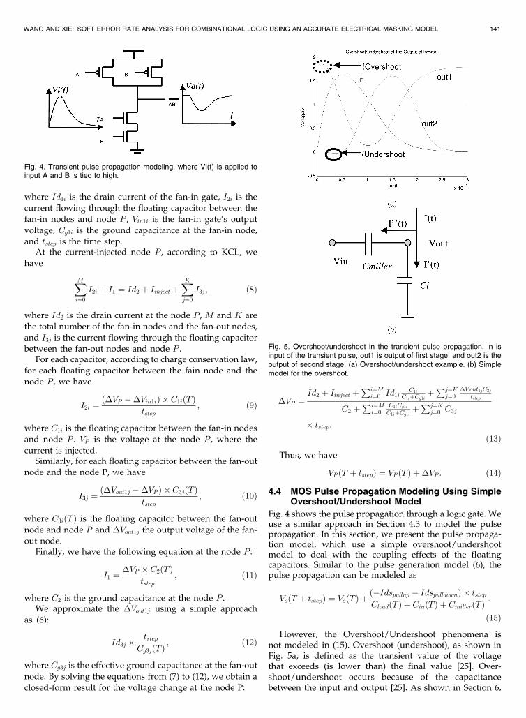
Fig. 4 shows the pulse propagation through a logic gate. Weuse a similar approach in Section 4.3 to model the pulsepropagation. In this section, we present the pulse propaga-tion model, which use a simple overshoot/undershootmodel to deal with the coupling effects of the floatingcapacitors. Similar to the pulse generation model (6), thepulse propagation can be modeled as
VoðT þ tstepÞ ¼ VoðT Þ þð�Idspullup � IdspulldownÞ � tstepCloadðT Þ þ CinðT Þ þ CmillerðT Þ
:
ð15Þ
However, the Overshoot/Undershoot phenomena isnot modeled in (15). Overshoot (undershoot), as shown inFig. 5a, is defined as the transient value of the voltagethat exceeds (is lower than) the final value [25]. Over-shoot/undershoot occurs because of the capacitancebetween the input and output [25]. As shown in Section 6,
WANG AND XIE: SOFT ERROR RATE ANALYSIS FOR COMBINATIONAL LOGIC USING AN ACCURATE ELECTRICAL MASKING MODEL 141
Fig. 4. Transient pulse propagation modeling, where Vi(t) is applied toinput A and B is tied to high.
Fig. 5. Overshoot/undershoot in the transient pulse propagation, in isinput of the transient pulse, out1 is output of first stage, and out2 is theoutput of second stage. (a) Overshoot/undershoot example. (b) Simplemodel for the overshoot.
overshoot/undershoot has great impact on the accuracyof estimation of the transient pulse propagation. Thus, theovershoot and undershoot have to be taken into accountin the transient error modelings.
In this study, we use a simple model to estimate theovershoot and undershoot. As shown in Fig. 5b, the ðCmillerÞcapacitance is the effective parasitic capacitance betweenthe input and output, and ðClÞ is the sum of the diffusioncapacitances ðCloadÞ and input capacitance of the load gatesðCinÞ. The drain current ðIdrainÞ contributes the change ofthe output voltage as well as the change of the voltageacross the input and output. Thus, the pulse waveformestimation, which includes the overshoot/undershoot ef-fect, can be performed as
VoðT þ tstepÞ ¼ VoðT Þ þCmillerðT Þ � �Vi � Idrain � tstep
ClðT Þ;
ð16Þ
where �Vi ¼ ðViðT þ tstepÞ � ViðT ÞÞ is the input voltagechange and Idrain ¼ Idspullup þ Idspulldown.
5 BLOCK-BASED SOFT ERROR ANALYSIS METHOD
In this section, we first present block-based soft erroranalysis algorithms based on our transient error modeling,and then, we show two heuristics to improve the speed ofthe transient analysis.
Fig. 6 shows the pseudocode of our SER estimationalgorithm. Our algorithm takes the netlist as input; itcomputes the soft error rate for the entire circuitconsidering three masking effects. We apply the faultsimulation techniques [20] to evaluate logic maskingeffect (Line 1-Line 4). A for loop iterates over the randominput vectors. In each iteration, the fault-free circuit isfirst simulated, and the sensitive gates in the gate netlistare determined using the critical path tracing techniques[20] (Line 3). With the sensitive gates determined, weupdate Psensitizedðn; POni; input patternÞ for thesenodes. Next, we take into account the electrical maskingeffects and the latch window effects. At Line 5, weestimate the SERðn; POni; input patternÞ, for each gate nin the netlist by calling the function EmaskðnetlistÞ.Finally, at Line 6, the soft error rate of the entire circuit iscalculated as the summation of each gate’s susceptibility.
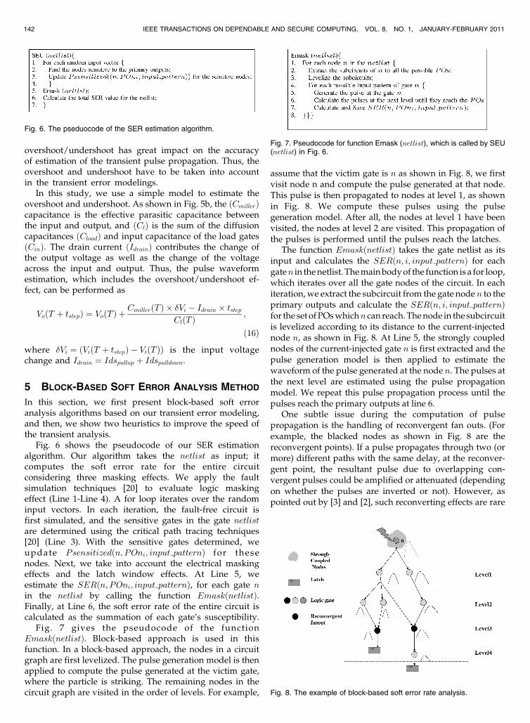
Fig. 7 gives the pseudocode of the functionEmaskðnetlistÞ. Block-based approach is used in thisfunction. In a block-based approach, the nodes in a circuitgraph are first levelized. The pulse generation model is thenapplied to compute the pulse generated at the victim gate,where the particle is striking. The remaining nodes in thecircuit graph are visited in the order of levels. For example,
assume that the victim gate is n as shown in Fig. 8, we firstvisit node n and compute the pulse generated at that node.This pulse is then propagated to nodes at level 1, as shownin Fig. 8. We compute these pulses using the pulsegeneration model. After all, the nodes at level 1 have beenvisited, the nodes at level 2 are visited. This propagation ofthe pulses is performed until the pulses reach the latches.
The function EmaskðnetlistÞ takes the gate netlist as itsinput and calculates the SERðn; i; input patternÞ for eachgaten in the netlist. The main body of the function is a for loop,which iterates over all the gate nodes of the circuit. In eachiteration, we extract the subcircuit from the gate node n to theprimary outputs and calculate the SERðn; i; input patternÞfor the set of POs whichn can reach. The node in the subcircuitis levelized according to its distance to the current-injectednode n, as shown in Fig. 8. At Line 5, the strongly couplednodes of the current-injected gate n is first extracted and thepulse generation model is then applied to estimate thewaveform of the pulse generated at the node n. The pulses atthe next level are estimated using the pulse propagationmodel. We repeat this pulse propagation process until thepulses reach the primary outputs at line 6.
One subtle issue during the computation of pulsepropagation is the handling of reconvergent fan outs. (Forexample, the blacked nodes as shown in Fig. 8 are thereconvergent points). If a pulse propagates through two (ormore) different paths with the same delay, at the reconver-gent point, the resultant pulse due to overlapping con-vergent pulses could be amplified or attenuated (dependingon whether the pulses are inverted or not). However, aspointed out by [3] and [2], such reconverting effects are rare
142 IEEE TRANSACTIONS ON DEPENDABLE AND SECURE COMPUTING, VOL. 8, NO. 1, JANUARY-FEBRUARY 2011
Fig. 6. The pseduocode of the SER estimation algorithm.
Fig. 7. Pseudocode for function Emask (netlist), which is called by SEU(netlist) in Fig. 6.
Fig. 8. The example of block-based soft error rate analysis.
situations in practice and have minimal impact on theaccuracy. Therefore, in our analysis, we follow the methodsuggested in [19] and choose the pulse with largerpulsewidth at the reconvergent point as its input to estimatethe output pulse waveform.
The SERðn; POni; input patternÞ value is computedbased on the characteristics of the pulse at the POni, thelatch window size, and the clock period for each primaryoutput at this subcircuit. From Line 4 to Line 7, the forloop enumerates all the possible input patterns since theinput pattern has large impact on the SEU immunity [32].Compared to our block-based method, the computationcomplexity of the path-based approach is an exponentialfunction of the number of gates in the circuits [29], [33],[34], [5], [6].
In our transient error analysis algorithm, two heuristicsare introduced to improve the performance.
1. Earlier termination: The transient pulse propagationcomputation can be terminated earlier for a parti-cular node if the pulse amplitude of transient voltageat any internal nodes is already less than V dd=2.
2. Adaptive time step: The choice of the time step usedin the simulation is important to the performance ofthe SER simulation. The naı̈ve scheme is to use auniform step for the entire simulation. However, thelarge range of the slope of the transient pulse makesit necessary to use nonuniform time step. For
example, the current pulse generated by the particlestrike has rapid rising time and much longer fallingtime. The step must be smaller enough to accuratelyestimate the rise of the pulse, while the step can berelaxed to compute the response of the falling edgeof the output.
6 ANALYSIS RESULTS
We implement our soft error analysis algorithm with theelectrical masking model in C++. In this section, we firstpresent our analysis results to show the accuracy and theruntime of the soft error analysis for combinational logics.We then compare our method against the existing techniquesin terms of accuracy, runtime, and memory requirements.
6.1 Accuracy and Runtime of Our Method
We first perform the transient pulse generation analysis andcompare it against HSPICE simulation. Next, we validatepulse propagation model on two simple logic gate net-works: the inverter chain and the two-input NAND chain.We then perform the soft error analysis on three smallcircuits and compare against HSPICE simulation result.Finally, we conduct the analysis on six ISCAS benchmarkcircuits (which are too large to obtain HSPICE simulationresult within reasonable runtime) to show the efficiency ofour soft error analysis method.
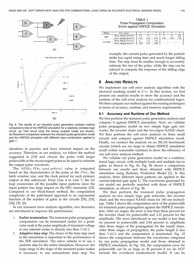
We validate our pulse generation model on a combina-tional logic circuit, with multiple loads and multiple fan-ingates, as shown in Fig. 9a. Fig. 9b shows a comparisonbetween our results and those obtained with HSPICEsimulation using Berkeley Prediction Model [1]. In thisanalysis, three different input patterns are applied to thecurrent-injected gate (gate 1). The waveforms generated byour model are perfectly matched with those of HSPICEsimulation, as shown in Fig. 9b.
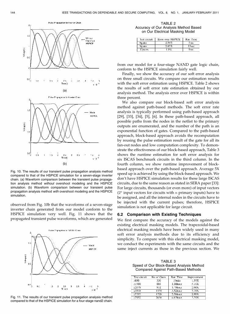
We then perform the transient pulse propagationanalysis on two simple logic gate networks: the inverterchain and the two-input NAND chain for 180 nm technol-ogy. Table 1 shows the computation error of the pulsewidthfor transient pulse propagation against the HSPICE simula-tion. After six stages, the error is less than three percent forthe inverter chain for pulsewidth and 3.22 percent for theamplitude. The error introduced in our model is less thansix percent in pulsewidth and 2.84 percent in amplitudeafter three stages of the propagation for the nand2 chain.After three stages of propagation, the pulse height is lessthan V dd=2 and the computation is terminated. Fig. 10shows the comparison between the waveforms computedby our pulse propagation model and those obtained inHSPICE simulation. In Fig. 10a, the computation error forpulsewidth can be as large as 30 percent if we do NOTinclude the overshoot (undershoot) model. It can be
WANG AND XIE: SOFT ERROR RATE ANALYSIS FOR COMBINATIONAL LOGIC USING AN ACCURATE ELECTRICAL MASKING MODEL 143
Fig. 9. The results of our transient pulse generation analysis methodcompared to that of the HSPICE simulation for a relatively complex logiccircuit. (a) Test circuit (only the strong coupled nodes are shown).(b) Waveform comparison between the transient pulse generation modeland the HSPICE simulation with different input combination applied togate 1.
TABLE 1Pulse Propagation Computation
Errors against HSPICE Simulation
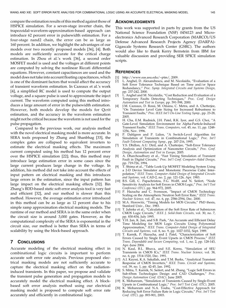
observed from Fig. 10b that the waveforms of a seven-stageinverter chain generated from our model conform to theHSPICE simulation very well. Fig. 11 shows that thepropagated transient pulse waveforms, which are generated
from our model for a four-stage NAND gate logic chain,conform to the HSPICE simulation fairly well.
Finally, we show the accuracy of our soft error analysison three small circuits. We compare our estimation resultswith the soft error estimation using HSPICE. Table 2 showsthe results of soft error rate estimation obtained by ouranalysis method. The analysis error over HSPICE is withinthree percent.
We also compare our block-based soft error analysismethod against path-based methods. The soft error rateanalysis is typically performed using path-based approach[29], [33], [34], [5], [6]. In these path-based approach, allpossible paths from the nodes in the netlist to the primaryoutputs are enumerated, and the number of the path is anexponential function of gates. Compared to the path-basedapproach, block-based approach avoids the recomputationby reusing the pulse estimation result of the gate for all itsfan-out nodes and low computation complexity. To demon-strate the effectiveness of our block-based approach, Table 3shows the runtime estimation for soft error analysis forsix ISCAS benchmark circuits in the third column. In thefourth column, we show runtime improvement of block-based approach over the path-based approach. Average 5Xspeed up is achieved by using the block-based approach. Wedon’t have HSPICE simulation results for these large ISCAScircuits, due to the same reason as stated in SERA paper [33]:For large circuits, thousands (or even more) of input vectors(2n input vectors for circuits with n primary inputs) have tobe assigned, and all the internal nodes in the circuits have tobe injected with the current pulses; therefore, HSPICEsimulation is not applicable for large circuit.
6.2 Comparison with Existing Techniques
We first compare the accuracy of the models against theexisting electrical masking models. The trapezoidal-basedelectrical masking models have been widely used in manysoft error analysis methods due to its efficiency andsimplicity. To compare with this electrical masking model,we conduct the experiments with the same circuits and thesame inject currents as those in the previous section. We
144 IEEE TRANSACTIONS ON DEPENDABLE AND SECURE COMPUTING, VOL. 8, NO. 1, JANUARY-FEBRUARY 2011
Fig. 10. The results of our transient pulse propagation analysis methodcompared to that of the HSPICE simulation for a seven-stage inverter
chain. (a) Waveform comparison between the transient pulse propaga-
tion analysis method without overshoot modeling and the HSPICE
simulation. (b) Waveform comparison between our transient pulse
propagation analysis method with overshoot modeling and the HSPICE
simulation.
Fig. 11. The results of our transient pulse propagation analysis methodcompared to that of the HSPICE simulation for a four-stage nand2 chain.
TABLE 2Accuracy of Our Analysis Method Based
on Our Electrical Masking Model
TABLE 3Speed of Our Block-Based Analysis Method
Compared Against Path-Based Methods
compare the estimation results of this method against those ofHSPICE simulation. For a seven-stage inverter chain, thetrapezoidal-waveform-approximation-based approach canintroduce 62 percent error in pulsewidth estimation. For afour-stage nand2 chain, the error can be as large as160 percent. In addition, we highlight the advantages of ourmodels over two recently proposed models [36], [4]. Bothmodels are sufficiently accurate for the critical chargeestimation. In Zhou et al.’s work [36], a second orderMOSFET model is used and the voltages at different pointsare computed by solving the nonlinear Riccati differentialequations. However, constant capacitances are used and themodel does not take into account floating capacitances, whichis one of the dominant factors that would affect the accuracyof transient waveform estimation. In Cazeaux et al.’s work[4], a simplified RC model is used to compute the outputvoltage, and a square pulse is used to approximate the injectcurrent. The waveform computed using this method intro-duces a large amount of error in the pulsewidth estimation.However, both models develop the models for Qcritestimation, and the accuracy in the waveform estimationmight not be critical because the waveform is not used for thepulse propagation.
Compared to the previous work, our analysis methodwith the novel electrical masking model is more accurate. InSERA tools proposed by Zhang and Shanbhag [33], thecomplex gates are collapsed to equivalent inverters toestimate the electrical masking effects. The maximumcurrent computed using his method has 12 percent errorover the HSPICE simulation [22]; thus, this method mayintroduce large estimation error in some cases since thelarge current produces large change in the voltage. Inaddition, his method did not take into account the effects ofinput pattern on electrical masking and this introduceslarge errors in the estimation, since the input pattern haslarge impact on the electrical masking effects [32]. BinZhang’s BDD-based static soft error analysis tool is very fastand efficient [32], and our method is slower than thismethod. However, the average estimation error introducedin this method can be as large as 12 percent due to hissimple ramp approximation electrical masking models. Theruntime of our method and SERA is in the same order whenthe circuit size is around 3,000 gates. However, as thecomputational complexity of the SERA is exponential in thecircuit size, our method is better than SERA in terms ofscalability by using the block-based approach.
7 CONCLUSIONS
Accurate modeling of the electrical masking effect incombinational logic circuits is important to performaccurate soft error rate analysis. Previous proposed elec-trical masking models are not sufficiently accurate tocapture the electrical masking effect on the radiation-induced transients. In this paper, we propose and validatethe transient pulse generation and propagation models toaccurately model the electrical masking effect. A block-based soft error analysis method using our electricalmasking model is proposed to compute soft error rateaccurately and efficiently in combinational logic.
ACKNOWLEDGMENTS
This work was supported in parts by grants from the USNational Science Foundation (NSF) 0454123 and Micro-electronics Advanced Research Corporation (MARCO)/USDefense Advanced Research Projects Agency (DARPA)-Gigascale Systems Research Center (GSRC). The authorswould also like to thank Kerry Bernstein from IBM forvaluable discussion and providing SER SPICE simulationscripts.
REFERENCES
[1] http://www.eas.asu.edu/~ptm/, 2009.[2] L. Anghel, D. Alexandrescu, and M. Nicolaidis, “Evaluation of a
Soft Error Tolerance Technique Based on Time and/or SpaceRedundancy,” Proc. Symp. Integrated Circuits and Systems Design,pp. 237-242, 2000.
[3] L. Anghel and M. Nicolaidis, “Cost Reduction and Evaluation of aTemporary Faults Detecting Techniques,” Proc. Conf. DesignAutomation and Test in Europe, pp. 591-598, 2000.
[4] J.M. Cazeaux, D. Rossi, M. Omana, C. Metra, and A. Chetterjee,“On Transistor Level Gate Sizing for Increased Robustness toTransient Faults,” Proc. IEEE Int’l On-Line Testing Symp., pp. 23-28,2005.
[5] H. Cha, E.M. Rudnick, J.H. Patel, R.K. Iyer, and G.S. Choi, “AGate-Level Simulation Environment for Alpha-Particle-InducedTransient Faults,” IEEE Trans. Computers, vol. 45, no. 11, pp. 1248-1256, Nov. 1996.
[6] P. Dahlgren and P. Liden, “A Switch-Level Algorithm forSimulation of Transients in Combinational Logic,” Proc. Int’lFault-Tolerant Computing Symp., pp. 207-216, 1995.
[7] Y.S. Dhillon, A.U. Diril, and A. Chatterjee, “Soft-Error ToleranceAnalysis and Optimization of Nanometer Circuits,” Proc. Conf.Design, Automation and Test in Europe, 2005.
[8] A. Dharchoudhury et al., “Fast Timing Simulation of TransientFault in Digital Circuits,” Proc. Int’l Conf. Computer-Aided Design,pp. 719-726, 1994.
[9] T. Shima et al., “Table Look-Up MOSFET Modeling System Usinga 2-D Device Simulator and Monotonic Piecewise Cubic Inter-polation,” IEEE Trans. Computer-Aided Design of Integrated Circuitsand Systems, vol. CAD-2, no. 2, pp. 121-126, Apr. 1983.
[10] B.S. Gill, C. Papachristou, F.G. Wolff, and N. Seifert, “NodeSensitivity Analysis for Soft Errors in CMOS Logic,” Proc. Int’l TestConference (ITC), pp. 964-972, 2005.
[11] P. Hazucha and C. Svensson, “Impact of CMOS TechnologyScaling on the Atmospheric Neutron Soft Error Rate,” IEEE Trans.Nuclear Science, vol. 47, no. 6, pp. 2586-2594, Dec. 2000.
[12] M.A. Horowitz, “Timing Models for MOS Circuits,” PhD thesis,Stanford Univ., Dec. 1983.
[13] T. Juhnke et al., “Calculation of the Soft Error Rate of SubmicronCMOS Logic Circuits,” IEEE J. Solid-State Circuits, vol. 30, no. 7,pp. 830-834, July 1995.
[14] Y.H. Jun, K. Jun, and S.B. Park, “An Accurate and Efficient DelayTime Modeling for MOS Logic Circuits Using PolynomialApproximation,” IEEE Trans. Computer-Aided Design of IntegratedCircuits and Systems, vol. 8, no. 9, pp. 1027-1032, Sept. 1989.
[15] T. Karnik, P. Hazucha, and J. Patel, “Characterization of SoftErrors Caused by Single Event Upsets in CMOS Process,” IEEETrans. Dependable and Secure Computing, vol. 1, no. 2, pp. 128-143,Apr.-June 2004.
[16] N. Kaul, B.L. Bhuva, and S.E. Kerns, “Simulation of SEUTransients in CMOS ICs,” IEEE Trans. Nuclear Science, vol. 38,no. 6, pp. 1514-1520, Dec. 1991.
[17] A.I. Kayssi, K.A. Sakallah, and T.M. Burks, “Analytical TransientResponse of CMOS Inverters,” IEEE Trans. Circuit and Systems,vol. 39, no. 1, pp. 42-45, Jan. 1992.
[18] S. Mitra, T. Karnik, N. Seifert, and M. Zhang, “Logic Soft Errors inSub-65nm Technologies Design and CAD Challenges,” Proc.Design Automation Conf. (DAC), June 2005.
[19] K. Mohanram, “Simulation of Transients Caused by Single-EventUpsets in Combinational Logic,” Proc. Int’l Test Conf. (ITC), 2005.
[20] K. Mohanram and N.A. Touba, “Cost-Effective Approach forReducing Soft Error Failure Rate in Logic Circuits,” Proc. Int’l TestConf. (ITC), pp. 893-901, 2003.
WANG AND XIE: SOFT ERROR RATE ANALYSIS FOR COMBINATIONAL LOGIC USING AN ACCURATE ELECTRICAL MASKING MODEL 145

[21] P.C. Murley and G.R. Srinivasan, “Soft-Error Monte CarloModeling Program, SEMM,” IBM J. Research and Development,vol. 1, pp. 109-118, Jan. 1996.
[22] A. Nabavi-Lishi and N.C. Rumin, “Inverter Models of CMOSGates for Supply Current and Delay Evaluation,” IEEE Trans.Computer-Aided Design of Integrated Circuits and Systems, vol. 13,no. 10, pp. 1271-1279, Oct. 1994.
[23] S. Nassif and E. Acar, “Advanced Waveform Models for nmRegime,” Proc. ACM/IEEE Int’l Workshop Timing Issues, 2004.
[24] M. Omana, G. Papasso, D. Rossi, and C. Metra, “A Model forTransient Fault Propagation in Combinatorial Logic,” Proc. Int’lOn-Line Testing Symp., 2003.
[25] J. Rabaey, A. Chandrakasan, and B. Nikolic, Digital IntegratedCircuits: A Design Perspective, second ed. Prentice Hall, 2003.
[26] R. Rao, K. Chopra, D. Blaauw, and D. Sylvester, “An EfficientStatic Algorithm for Soft Error Rate Analysis of CombinationalCircuits,” Proc. ACM/IEEE Design Automation and Test in EuropeConf. (DATE), Mar. 2006.
[27] R. Rao, K. Chopra, D. Blaauw, and D. Sylvester, “Computing theSoft Error Rate of a Combinational Logic Circuit Using Para-meterized Descriptors,” IEEE Trans. Computer-Aided Design ofIntegrated Circuits and Systems, vol. 26, no. 3, pp. 468-479, Mar.2007.
[28] T. Sakurai and A.R. Newton, “Alpha-Power Law MOSFET Modeland Its Applications to CMOS Inverter Delay and OtherFormulas,” IEEE J. Solid-State Circuits, vol. 25, no. 2, pp. 584-593,Apr. 1990.
[29] P. Shivakumar, M. Kistler, S.W. Keckler, D. Burger, and L. Alvisi,“Modeling the Effect of Technology Trends on Soft Error Rate ofCombinational Logic,” Proc Int’l Conf. Dependable Systems andNetworks, pp. 389-398, June 2002.
[30] C. Visweswariah, K. Ravindran, K. Kalafala, S.G. Walker, and S.Narayan, “First-Order Incremental Block-Based Statistical TimingAnalysis,” Proc. Design Automation Conf. (DAC), pp. 331-336, June2004.
[31] J. Vlach and K. Singhal, Computer Methods for Circuit Analysis andDesign, second ed. John Wiley & Sons, Inc., 1993.
[32] B. Zhang, W.S. Wang, and M. Orshansky, “FASER: Fast Analysisof Soft Error Susceptibility for Cell-Based Designs,” Proc. Int’lSymp. Quality Electronic Design (ISQED), 2006.
[33] M. Zhang and N. Shanbhag, “A Soft Error Rate AnalysisMethodology,” Proc. Int’l Conf. Computer Aided Design (ICCAD),pp. 111-118, 2004.
[34] C. Zhao, X.L. Bai, and S. Dey, “A Scalable Soft Spot AnalysisMethodology for Compound Noise Effects in Nano-MeterCircuits,” Proc. 41st Ann. Conf. Design Automation, pp. 894-899,2004.
[35] Q. Zhou and K. Mohanram, “Cost-Effective Radiation HardeningTechnique for Logic Circuits,” Proc. Int’l Conf. Computer-AidedDesign, pp. 100-106, 2004.
[36] Q. Zhou and K. Mohanram, “Gate Sizing to Radiation HardenCombinational Logic,” IEEE Trans. Computer-Aided Design ofIntegrated Circuits and Systems, vol. 25, no. 1, pp. 155-166, Jan. 2006.
[37] J. Ziegler, “IBM Experiments in Soft Fails in Computer Electro-nics,” IBM J. Research and Development, vol. 1, pp. 3-18, 1996.
Feng Wang (S’05) received the BS degree inelectronic engineering from Fundan University,Shanghai, China, in 1997, the MS degree inelectrical engineering from Ohio University,Athens, in 2004, and the PhD degree incomputer science and engineering from thePennsylvania State University, University Park,in 2008. He is currently with Qualcomm Incor-poration, working on architecture exploration for3D integration. His research interests include
computer architecture, VLSI design, and electronics design automation.He received ASPDAC Best Paper Award in 2008. He is a studentmember of the IEEE.
Yuan Xie (SM’07) received the BS degree inelectronic engineering from Tsinghua University,Beijing, China, in 1997, and the MS and PhDdegrees in electrical engineering from PrincetonUniversity, New Jersey, in 1999 and 2002,respectively. He is an assistant professor in theComputer Science and Engineering Depart-ment, The Pennsylvania State University (PennState), University Park. Before joining PennState in the Fall of 2003, he was with IBM
Microelectronic Divisions Worldwide Design Center. His researchinterests include VLSI Design, computer architecture, embeddedsystems design, and electronics design automation. He was a recipientof the SRC Inventor Recognition Award in 2002 and the US NationalScience Foundation CAREER Award in 2006. He is a member of theACM, and a senior member of the IEEE.
. For more information on this or any other computing topic,please visit our Digital Library at www.computer.org/publications/dlib.
146 IEEE TRANSACTIONS ON DEPENDABLE AND SECURE COMPUTING, VOL. 8, NO. 1, JANUARY-FEBRUARY 2011