ieee transactions on mobile computing, vol. 15, no. …
TRANSCRIPT
What Am I Looking At? Low-Power Radio-OpticalBeacons for In-View Recognition on Smart-Glass
Ashwin Ashok, Chenren Xu, Tam Vu, Marco Gruteser, Rich Howard,
Yanyong Zhang, Narayan Mandayam, Wenjia Yuan, and Kristin Dana
Abstract—Applications on wearable personal imaging devices, or Smart-glasses as they are called, can largely benefit from accurate
and energy-efficient recognition of objects that are within the user’s view. Existing solutions such as optical or computer vision
approaches are too energy intensive, while low-power active radio tags suffer from imprecise orientation estimates. To address this
challenge, this paper presents the design, implementation, and evaluation of a radio-optical hybrid system where a radio-optical
transmitter, or tag, whose radio-optical beacons are used for accurate relative orientation tracking of tagged objects by a wearable
radio-optical receiver. A low-power radio link that conveys identity is used to reduce the battery drain by synchronizing the radio-optical
transmitter and receiver so that extremely short optical (infrared) pulses are sufficient for orientation (angle and distance) estimation.
Through extensive experiments with our prototype we show that our system can achieve orientation estimates with 1-to-2 degree
accuracy and within 40 cm ranging error, with a maximum range of 9 m in typical indoor use cases. With a tag and receiver battery
power consumption of 81 mW and 90 mW, respectively, our radio-optical tags and receiver are at least 1.5� energy efficient than prior
works in this space.
Index Terms—Smart-glass, low-power, positioning, recognition, RFID, optical, infrared, wearables, tags
Ç
1 INTRODUCTION
SMART-GLASS or wearable personal imaging devices pro-vide endless possibilities for applications that can inter-
act with the physical world. Today, there are multiple smart-glass devices commercially available in the market enablingplethora of interactive applications ranging from visualizingcontent on a smart-glass heads-up display [1], [2] to virtuallyinteracting with objects in physical space [3], [4].
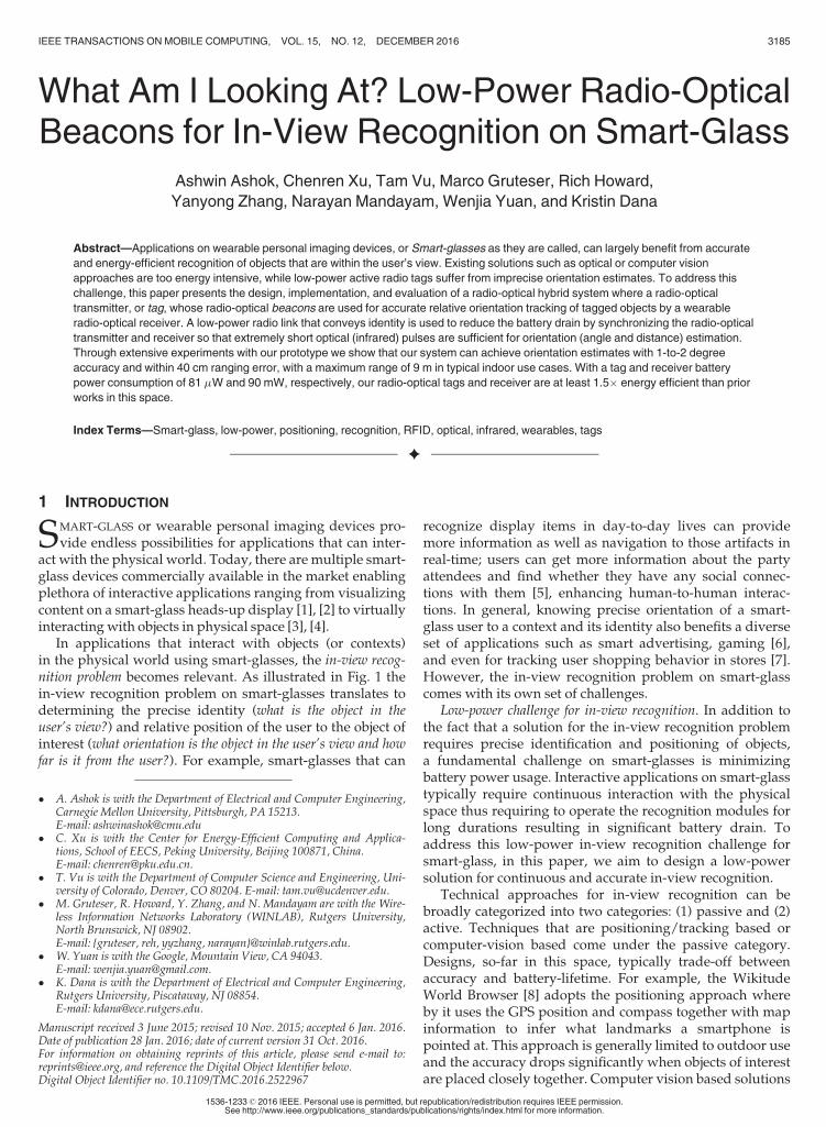
In applications that interact with objects (or contexts)in the physical world using smart-glasses, the in-view recog-nition problem becomes relevant. As illustrated in Fig. 1 thein-view recognition problem on smart-glasses translates todetermining the precise identity (what is the object in theuser’s view?) and relative position of the user to the object ofinterest (what orientation is the object in the user’s view and howfar is it from the user?). For example, smart-glasses that can
recognize display items in day-to-day lives can providemore information as well as navigation to those artifacts inreal-time; users can get more information about the partyattendees and find whether they have any social connec-tions with them [5], enhancing human-to-human interac-tions. In general, knowing precise orientation of a smart-glass user to a context and its identity also benefits a diverseset of applications such as smart advertising, gaming [6],and even for tracking user shopping behavior in stores [7].However, the in-view recognition problem on smart-glasscomes with its own set of challenges.
Low-power challenge for in-view recognition. In addition tothe fact that a solution for the in-view recognition problemrequires precise identification and positioning of objects,a fundamental challenge on smart-glasses is minimizingbattery power usage. Interactive applications on smart-glasstypically require continuous interaction with the physicalspace thus requiring to operate the recognition modules forlong durations resulting in significant battery drain. Toaddress this low-power in-view recognition challenge forsmart-glass, in this paper, we aim to design a low-powersolution for continuous and accurate in-view recognition.
Technical approaches for in-view recognition can bebroadly categorized into two categories: (1) passive and (2)active. Techniques that are positioning/tracking based orcomputer-vision based come under the passive category.Designs, so-far in this space, typically trade-off betweenaccuracy and battery-lifetime. For example, the WikitudeWorld Browser [8] adopts the positioning approach whereby it uses the GPS position and compass together with mapinformation to infer what landmarks a smartphone ispointed at. This approach is generally limited to outdoor useand the accuracy drops significantly when objects of interestare placed closely together. Computer vision based solutions
� A. Ashok is with the Department of Electrical and Computer Engineering,Carnegie Mellon University, Pittsburgh, PA 15213.E-mail: [email protected]
� C. Xu is with the Center for Energy-Efficient Computing and Applica-tions, School of EECS, Peking University, Beijing 100871, China.E-mail: [email protected].
� T. Vu is with the Department of Computer Science and Engineering, Uni-versity of Colorado, Denver, CO 80204. E-mail: [email protected].
� M. Gruteser, R. Howard, Y. Zhang, and N. Mandayam are with the Wire-less Information Networks Laboratory (WINLAB), Rutgers University,North Brunswick, NJ 08902.E-mail: {gruteser, reh, yyzhang, narayan}@winlab.rutgers.edu.
� W. Yuan is with the Google, Mountain View, CA 94043.E-mail: [email protected].
� K. Dana is with the Department of Electrical and Computer Engineering,Rutgers University, Piscataway, NJ 08854.E-mail: [email protected].
Manuscript received 3 June 2015; revised 10 Nov. 2015; accepted 6 Jan. 2016.Date of publication 28 Jan. 2016; date of current version 31 Oct. 2016.For information on obtaining reprints of this article, please send e-mail to:[email protected], and reference the Digital Object Identifier below.Digital Object Identifier no. 10.1109/TMC.2016.2522967
IEEE TRANSACTIONS ON MOBILE COMPUTING, VOL. 15, NO. 12, DECEMBER 2016 3185
1536-1233� 2016 IEEE. Personal use is permitted, but republication/redistribution requires IEEE permission.See http://www.ieee.org/publications_standards/publications/rights/index.html for more information.
analyze the camera footage from a mobile device to recog-nize objects, which works best with well-known land-marks [9] or previously recognized subjects/objects [10]. Theaccuracy of this approach degrades, however, as lightingconditions deteriorate, the number of candidate objects/sub-jects becomes very large, or the objects themselves look verysimilar (e.g., boxes in a warehouse). More importantly, cam-era operations are energy intensive and usually not opti-mized for long-term usage on battery power. Activeapproaches involve tagging objects of interest with a trans-mitting device, that emits signals carrying a unique identify-ing code pertaining to the object. An equivalent receiver thatcommunicates with the transmitter recognizes the taggedobject by decoding the identification code.
There has been a multitude of work in the active radio-frequency identification (RFID) community for positioningand localizing objects using radio signal strength (RSS);particularly indoors. However, using radio signal strengthfor positioning is very challenging due to multipath effect.Recent work on active RFIDs [11], [12] have been able topromise precise positioning accuracies. However, thesetechniques trade-off accuracy with energy-consumptionand/or cost in consideration for smart-glass usage. Forexample, in [12] directional antennas provide the key bene-fit of accurately triangulating the reflected frequency-mod-ulated continuous wave (FMCW) radio signal paths andpin-pointing the object’s position. However, this approachmay not be suitable for smart-glasses due to the highpower consumption for generating the FMCW signals.In [11] though the solution achieves very precise position-ing, the use of a R420 RFID reader makes the approach tobe power consuming and expensive for integration onsmart-glasses.
Apart from RF other possible modularities for position-ing include using ultrasound. With its low propagationspeed, ultrasound signals allow precise time-of-flight basedangle-of-arrival (AoA) estimates. However, this is achievedat the cost of increased receiver size (5–10 cm) and a signifi-cant amount of energy to overcome it’s exponential path-loss propagation; as opposed to inverse-square for electro-magnetic waves. In addition, recent works on eye-gazetracking systems [13], [14] have shown to precisely trackwhat part of the scene is the user’s eye concentrated upon.However, this solves only one dimension of the recognitionproblem as the identity of the object that the user is actually“looking at” still remains unknown. In general, solutions
so-far in the eye-gazing have required intricate or expensivehardware design.
A hybrid radio-optical beaconing approach. We address thelow-power challenge in-view recognition problem through ahybrid radio-optical system design. Our design adopts theactive approach and integrates near-IR (infrared) based orien-tation tracking with object identification using active RFIDs.The key component of our design is the radio-optical signal,or beacon as we will refer to, which is an ensemble of a radiopacket and an IR signal pulse. Infrared signals, due to theirhigh directionality, can lead to precise orientation trackingthrough angle-of-arrival and distance estimation with a rela-tively small receiver, due to their small 850 nm wavelength.Themain advantage of our approach is that it efficientlymini-mizes energy consumption by synchronizing the IR linkbetween the transmitter and receiver using a RF side-channel.This enables the receiver to know exactly when to expect theIR pulse and thus allows for using extremely short IR pulses(order of ms) due to tight synchronization between the trans-mitter and receiver. The receiver uses the ratio of the receivedIR power over a photodiode array to determine the angle-of-arrival of the signal and uses the sum of absolute receivedpowers to estimate the distance between the transmitter andreceiver. The radio link is used to communicate the identitythrough a unique code embedded in the radio-packet.
Advantages of proposed approach. The key contributionthrough our proposed design in this paper is the radio-synchronized IR signaling. Since the transmitter and receiverare synchronized it allows to operate both, the IR and radiolinks at extremely low power thus optimizing battery usage.In addition to reduced energy consumption, short IR pulsesalso lead to a simplified IR receiver design – instead of requir-ing an infrared communication receiver (such as in TV remotecontrols), a synchronized energy detection circuit suffices.Existing IR technologies ( [15], [16]) typically trade off energyconsumption with range and/or beamwidth (angular-range).For example, GigaIR [16] can achieve low energy consump-tion with extremely narrow IR beams, but only within veryshort distances (i.e., tens of centimeters). The synchronizationbetween the radio and optical links also makes it possible toestimate the 3D spatial position coordinates of the tags usinga single radio-optical beacon sample at the receiver.
In summary, the key contributions from our work in thispaper are as follows:
1. We propose a solution for low-power in-view recog-nition of objects in space using a hybrid, radio-optical,beaconing approach. We propose a design that lever-ages the high directionality of IR signals for preciseorientation tracking and low-power nature of RFIDsto communicate identity. We develop a synchroniza-tion protocol to reliably associate the IR signals withthe radio link and enabling use of extremely short IRpulses conserving significant battery power throughsynchronous transmission and reception.
2. We implement a proof-of-concept prototype radio-optical beaconing system. We design he hardwareand software of a radio-optical transmitter (tag) andreceiver, and develop a positioning application onan Android smart-glass heads-up display that inte-grates with the receiver. The application identifies
Fig. 1. Illustrating in-view recognition using smart-glasses.
3186 IEEE TRANSACTIONS ON MOBILE COMPUTING, VOL. 15, NO. 12, DECEMBER 2016
and positions objects in user’s view fit with theradio-optical tag.
3. We evaluate the tag and receiver power consump-tion. We estimate that our tag design can offer bat-tery lifetimes upto few years. We discuss the effectof important design parameters such as IR pulselength, beaconing period and beaconing rate on tagpower consumption. Overall, we show that the tagand receiver are least 1.5� power efficient comparedto prior tag based approaches.
4. We experimentally evaluate the positioning accuracyof our approach in real-world settings with tags fitonto objects and the receiver fit on eye-glasses. Weshow that AoA and distance estimation errors arelimited within 1–2 degrees and 40 cm respectively,over a maximum range of 9 m. We also show thatour prototype in-view recognition application on thesmart-glass receiver achieves 97 percent accuracy.
The outline of this paper is as follows: Section 2 moti-vates our work in this paper; Section 3 presents the systemdesign in detail; Section 4 describes the prototype designand Section 5 discusses evaluations and results; Section 6discusses challenges and limitations of this work andSection 7 concludes the paper.
2 MOTIVATION
2.1 Requirements of In-View Recognition
We identify three key requirements for the task of in-viewobject recognition using smart-glasses.
Low battery power consumption.Due to the continuous oper-ation requirement on battery powered devices it is criticallyimportant to significantly minimize power consumption onboth, the tag and receiver. In this work we consider that both,tag and receiver, are battery operated. We envision that thetags will be fit onto mobile objects. The number of tagsrequired for a finite space may be large and thus it becomesimperative to significantly reduce tag power consumptionsuch that their batteries can operate for long durations(months or even years) without needing replacement. In thiswork we take a standpoint that the receiver will be fit onto awearable device such as heads-up displays or eye-glasses.Though it is usually much easier to recharge the wearabledevices than the tags it is fundamentally important that thein-view recognition modules on the receiver can operate lowpower usage considering it must be kept switched ON forlong usage durations of hours or days.
Precise orientation estimation. The task of identifying mul-tiple objects within a user’s view demands precise orienta-tion towards these objects (knowing how far and at whatorientation is the object in user’s view), and association
between object spatial positions and their identity (knowingwhat it is). Determining such orientations is similar to esti-mating angle-of-arrival of a signal from the object to a refer-ence point on user’s view. Accurate object tracking willhave very low AoA error tolerance. For example, with 1mspacing between objects and 3 m distance between the userand the objects, the AoA error tolerance so as to distinguishthe objects in the user’s view is about 10 degrees.
Small size. It is important that an enabling technologymust make it possible for miniaturization; transmitters asintegrate into small mobile objects and receiver as it mustbe integrated into a wearable device. For mounting areceiver onto smart-glasses, desirable receiver sizes will beof the order of centimeters and smaller.
2.2 Advantages and Limitations of CandidateTechnologies for In-View Recognition
In Table 1, we compare individual candidate technologies forsolving the in-view recognition problem. AoA using RF sig-nal strength alone is very challenging due to the multipathnature of radio signals—the angle resolution is fundamen-tally limited to a few radians. However, communicatinginformation through radio signals consumes very less power.
Ultrasound signals are good candidates for AoA estima-tion due to their low propagation speed; enabling preciseranging through accurate time-of-flight estimates. However,ultrasound transducers are costlier than radio antennas andultrasound receivers have minimum size requirements dueto its relatively long wavelength; the minimum distance ofseparation between ultrasound receivers on an array isfrom few cm to tens of cm.
The highly directional nature of optical signals makes it aviable candidate for accurate AoA estimation. Visible lightbased systems, e.g., using cameras, perform accurate pose-estimation to determine AoA based on preset markers, butcameras are energy intensive and unsuitable for long-dura-tion operations.
IR signals, that are unobtrusive as they are invisible to thehuman eye, can give precise AoA estimation and rang-ing [17], [18]. However, IR wireless communication is muchless energy efficient than RF because it has to overcomemuch higher ambient noise levels than in the RF spectrum.This means that transmitting even 1 bit of information usingIR communication will incur significantly higher energythan RF.
2.3 Why Use Radio-Optical Approach
We learned that adopting a single technology will result intrading off accuracy with battery power or vice-versa.In this regard, we explore a strategy that blends multipletechnologies leveraging the key advantage(s) of each
TABLE 1Comparing Different Positioning Technologies
Technology ID AoA accuracy Range Size (order of) Battery life
RF ID from data-packets low NLOS(<100 m) few cms months-yearsUltrasound require side channel high LOS (<14 m) few inches monthsCamera image recognition high LOS (10 s of m) mm-10 s cm 1–2 daysIR encode bits as pulses high LOS(<10 m) mm-cm few days
Size of cameras can trade off with speed and image quality.
ASHOK ET AL.: WHAT AM I LOOKING AT? LOW-POWER RADIO-OPTICAL BEACONS FOR IN-VIEW RECOGNITION ON SMART-GLASS 3187
technology. In particular, we propose to bring togetherradio and optical (using IR signals) technologies to addressthe in-view recognition requirements. This hybrid approachcan provide the following key benefits:
Energy efficiency through radio synchronization. With theavailability of two orthogonal technologies it will be possi-ble to use one to synchronize communication on one linkusing the other. Our proposed approach uses the radio linkto synchronize the IR link. This approach enables to useextremely short IR pulses for positioning and the radio linkfor communication, conserving considerable battery power.
Precise AoA using IR signal strength. IR signals due to theirhigh directionality, can provide robust AoA estimation andranging. It is possible to determine AoA and distance usingthe signal strength alone of an IR pulse of a predeterminedduration (kindly refer to the Appendix, which can be foundon the Computer Society Digital Library at http://doi.ieeecomputersociety.org/10.1109/TMC.2016.2522967), forderivation of AoA estimation using IR signal strength). IRsignals are unobtrusive for humans and do not travelthrough obstructions, reducing the likelihood of includingobjects that are not directly within sight.
Size reduction through simple design. The small size ofRFIDs and the simplicity of the required IR circuitry (apulse generator at the transmitter, energy detector at thereceiver) makes the design conducive for miniaturization.
2.4 Applications
The radio-optical approach for the in-view recognitionproblem can enable plethora of applications requiring con-tinuous battery usage and precise recognition. In particular,when integrated with smart-glasses, users can be navigatedto tagged objects in stores, books in a library, items in a gro-cery store or warehouse etc. Smart-glasses can also be usedto distinguish and locate different objects in a clutteredenvironment. In addition, precise orientation mappingbecomes critical for augmented reality applications wherephysical world 3D coordinates of objects need to be mappedto the user’s view. Apart from standalone smart-glass appli-cations, the radio-synchronized IR signaling approach canbe used as low-power signaling technique, for example inRFID systems or light based communication systems.
3 RADIO-OPTICAL BEACONING SYSTEM DESIGN
In-view recognition of an object on smart-glass using ourradio-optical beaconing system will involve tagging objectsof interest with a radio-optical tag that communicates with anequivalent radio-optical receiver fit on the smart-glass. Theradio-optical receiver identifies the radio-optical tag using
the unique identification code transmitted through a radiolink. The receiver determines it’s spatial orientation with thetag by estimating the AoA and distance using the signalstrength of the IR signal received through an optical link. Byassociating the orientation with the identity of the tag, thereceiver positions the taggedwithin the user’s field-of-view.
The key novelty of our proposed design is the radio-synchronized IR signaling approach. In this approach, theradio and the IR links between the tag and the receiver aresynchronized through our proposed synchronization proto-col. This protocol enables the receiver to know exactly whenthe IR signal will be transmitted from the tag. This timinginformation is computed at the receiver by detecting thearrival time of the corresponding radio packet. Throughthis radio-synchronized IR signaling approach we mainlyleverage three key benefits to address the in-view recogni-tion problem for smart-glasses:
� Extremely short IR pulsing: It is possible to use anextremely short IR pulse for IR signaling hence pro-viding significant gains in energy efficiency,
� Synchronized radio and IR links: It is possible to esti-mate precisely the arrival time of the IR signal usingan orthogonal (radio) side-channel enabling easyassociation of orientation with identity and alsoavoiding a dedicated synchronization circuitry, and
� Collision avoidance: It is possible to preserve the accu-racy of orientation estimation even in multi-tag envi-ronments by avoiding IR signal collisions usingprecise IR signal arrival time estimates throughradio-synchronized link.
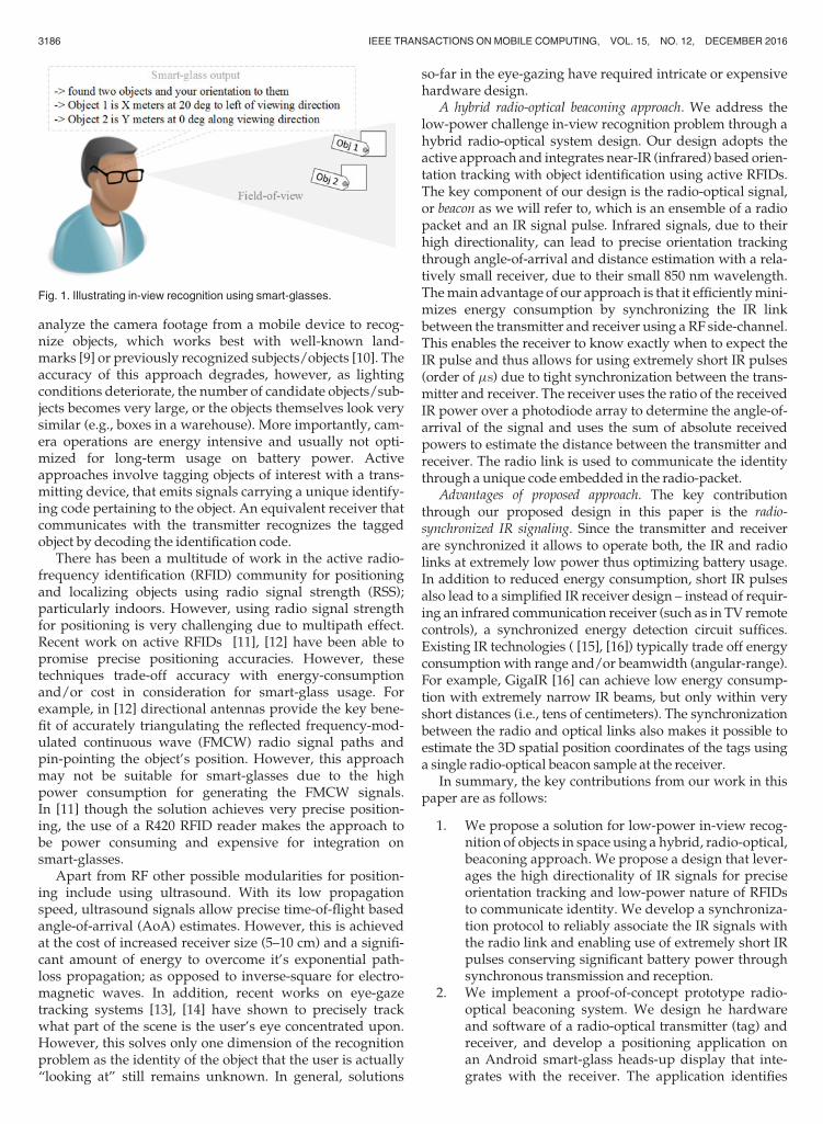
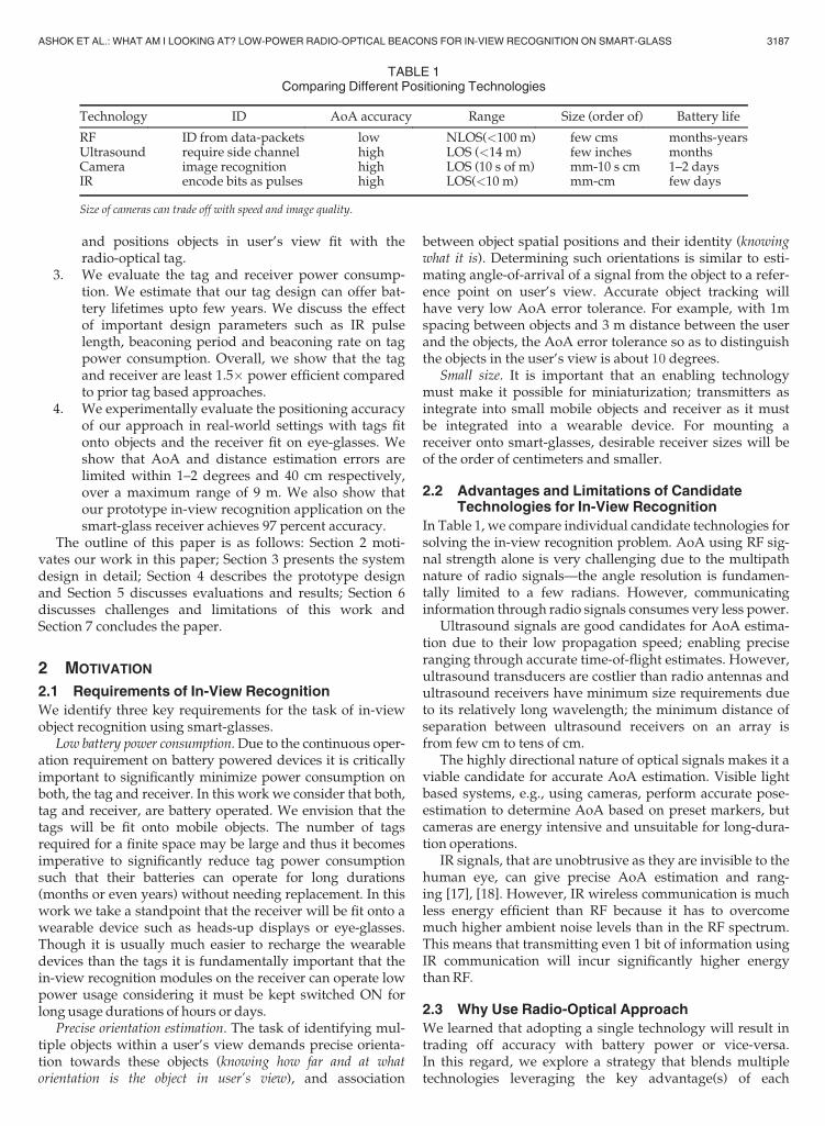
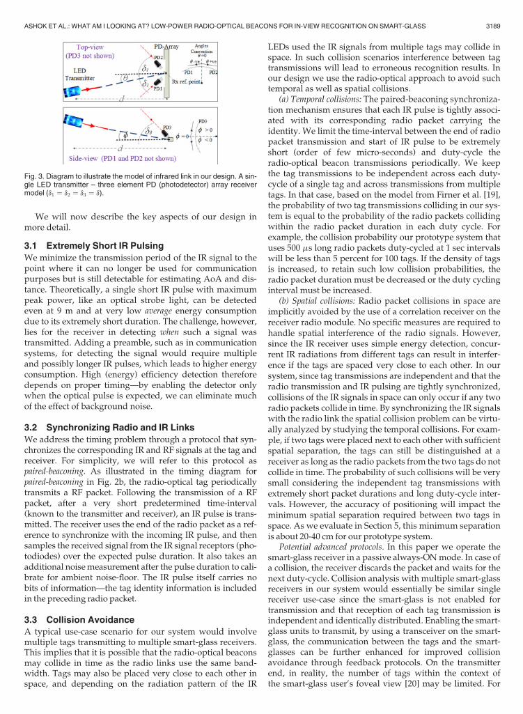
We illustrate our proposed radio-optical beaconing sys-tem through the architecture diagram in Fig. 2a. Wedescribe the IR link through our model illustrated in Fig. 3.In this model, we consider a three-element photodetector IRreceiver that samples IR signals from an IR LED transmitteron the radio-optical tag. We define AoA as the anglebetween the receiver surface normal and the vector connect-ing the transmitter and the depicted reference point at thecenter of the photodetector array; on the horizontal plane(azimuthal) as u and vertical plane (polar) as f. The photodi-odes are rotated by an angle d from the surface normal suchthat the angle between the LED and the vector in directionof photodiodes 1, 2 and 3 is u � d and u þ d, and fþ d,respectively. We use dir to represent the width of the IRpulse and d as the distance along the viewing axis betweenthe tag and receiver. We refer the reader to the Appendix,available in the online supplementary material, for themathematical derivation for determining AoA (u and f) anddistance (d) from IR signal strength.
Fig. 2. (a) Radio-optical beaconing system architecture. The IR beacon is used for accurate positioning through AoA, while synchronization and IDcommunication is through radio. (b) Timing diagram of the paired-beaconing protocol over one duty-cycle period; this example uses two tags.
3188 IEEE TRANSACTIONS ON MOBILE COMPUTING, VOL. 15, NO. 12, DECEMBER 2016
We will now describe the key aspects of our design inmore detail.
3.1 Extremely Short IR Pulsing
We minimize the transmission period of the IR signal to thepoint where it can no longer be used for communicationpurposes but is still detectable for estimating AoA and dis-tance. Theoretically, a single short IR pulse with maximumpeak power, like an optical strobe light, can be detectedeven at 9 m and at very low average energy consumptiondue to its extremely short duration. The challenge, however,lies for the receiver in detecting when such a signal wastransmitted. Adding a preamble, such as in communicationsystems, for detecting the signal would require multipleand possibly longer IR pulses, which leads to higher energyconsumption. High (energy) efficiency detection thereforedepends on proper timing—by enabling the detector onlywhen the optical pulse is expected, we can eliminate muchof the effect of background noise.
3.2 Synchronizing Radio and IR Links
We address the timing problem through a protocol that syn-chronizes the corresponding IR and RF signals at the tag andreceiver. For simplicity, we will refer to this protocol aspaired-beaconing. As illustrated in the timing diagram forpaired-beaconing in Fig. 2b, the radio-optical tag periodicallytransmits a RF packet. Following the transmission of a RFpacket, after a very short predetermined time-interval(known to the transmitter and receiver), an IR pulse is trans-mitted. The receiver uses the end of the radio packet as a ref-erence to synchronize with the incoming IR pulse, and thensamples the received signal from the IR signal receptors (pho-todiodes) over the expected pulse duration. It also takes anadditional noisemeasurement after the pulse duration to cali-brate for ambient noise-floor. The IR pulse itself carries nobits of information—the tag identity information is includedin the preceding radio packet.
3.3 Collision Avoidance
A typical use-case scenario for our system would involvemultiple tags transmitting to multiple smart-glass receivers.This implies that it is possible that the radio-optical beaconsmay collide in time as the radio links use the same band-width. Tags may also be placed very close to each other inspace, and depending on the radiation pattern of the IR
LEDs used the IR signals from multiple tags may collide inspace. In such collision scenarios interference between tagtransmissions will lead to erroneous recognition results. Inour design we use the radio-optical approach to avoid suchtemporal as well as spatial collisions.
(a) Temporal collisions: The paired-beaconing synchroniza-tion mechanism ensures that each IR pulse is tightly associ-ated with its corresponding radio packet carrying theidentity. We limit the time-interval between the end of radiopacket transmission and start of IR pulse to be extremelyshort (order of few micro-seconds) and duty-cycle theradio-optical beacon transmissions periodically. We keepthe tag transmissions to be independent across each duty-cycle of a single tag and across transmissions from multipletags. In that case, based on the model from Firner et al. [19],the probability of two tag transmissions colliding in our sys-tem is equal to the probability of the radio packets collidingwithin the radio packet duration in each duty cycle. Forexample, the collision probability our prototype system thatuses 500 ms long radio packets duty-cycled at 1 sec intervalswill be less than 5 percent for 100 tags. If the density of tagsis increased, to retain such low collision probabilities, theradio packet duration must be decreased or the duty cyclinginterval must be increased.
(b) Spatial collisions: Radio packet collisions in space areimplicitly avoided by the use of a correlation receiver on thereceiver radio module. No specific measures are required tohandle spatial interference of the radio signals. However,since the IR receiver uses simple energy detection, concur-rent IR radiations from different tags can result in interfer-ence if the tags are spaced very close to each other. In oursystem, since tag transmissions are independent and that theradio transmission and IR pulsing are tightly synchronized,collisions of the IR signals in space can only occur if any tworadio packets collide in time. By synchronizing the IR signalswith the radio link the spatial collision problem can be virtu-ally analyzed by studying the temporal collisions. For exam-ple, if two tags were placed next to each other with sufficientspatial separation, the tags can still be distinguished at areceiver as long as the radio packets from the two tags do notcollide in time. The probability of such collisions will be verysmall considering the independent tag transmissions withextremely short packet durations and long duty-cycle inter-vals. However, the accuracy of positioning will impact theminimum spatial separation required between two tags inspace. As we evaluate in Section 5, this minimum separationis about 20-40 cm for our prototype system.
Potential advanced protocols. In this paper we operate thesmart-glass receiver in a passive always-ONmode. In case ofa collision, the receiver discards the packet and waits for thenext duty-cycle. Collision analysis with multiple smart-glassreceivers in our system would essentially be similar singlereceiver use-case since the smart-glass is not enabled fortransmission and that reception of each tag transmission isindependent and identically distributed. Enabling the smart-glass units to transmit, by using a transceiver on the smart-glass, the communication between the tags and the smart-glasses can be further enhanced for improved collisionavoidance through feedback protocols. On the transmitterend, in reality, the number of tags within the context ofthe smart-glass user’s foveal view [20] may be limited. For
Fig. 3. Diagram to illustrate the model of infrared link in our design. A sin-gle LED transmitter – three element PD (photodetector) array receivermodel (d1 ¼ d2 ¼ d3 ¼ d).
ASHOK ET AL.: WHAT AM I LOOKING AT? LOW-POWER RADIO-OPTICAL BEACONS FOR IN-VIEW RECOGNITION ON SMART-GLASS 3189
example, there may be 1,000 tags in a storehouse but thenumber of tags within the context of the user’s view may belimited to those within one or two racks. This means that itmay be possible to adopt intelligent filtering schemes to limitthe number of tags the receiver would decode from in a par-ticular space and time context. For example, one simpleapproach may be to engineer the system to filter the tags notwithin a calibrated radio range (RSSI is less than a threshold).
In this paper, we have focused on emphasizing the bene-fits of radio-synchronized IR signaling, leaving advancedhardware and protocol design challenges for future work.
4 PROTOTYPE DESIGN
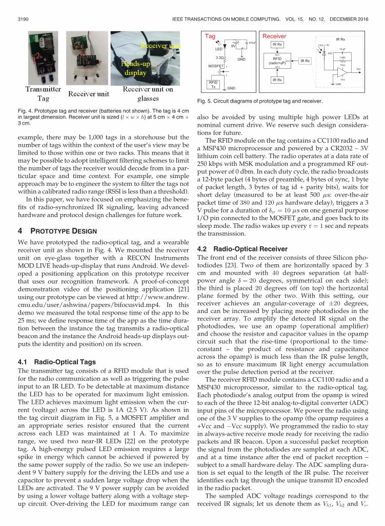
We have prototyped the radio-optical tag, and a wearablereceiver unit as shown in Fig. 4. We mounted the receiverunit on eye-glass together with a RECON InstrumentsMOD LIVE heads-up-display that runs Android. We devel-oped a positioning application on this prototype receiverthat uses our recognition framework. A proof-of-conceptdemonstration video of the positioning application [21]using our prototype can be viewed at http://www.andrew.cmu.edu/user/ashwina/papers/bifocusvid.mp4. In thisdemo we measured the total response time of the app to be25 ms; we define response time of the app as the time dura-tion between the instance the tag transmits a radio-opticalbeacon and the instance the Android heads-up displays out-puts the identity and position) on its screen.
4.1 Radio-Optical Tags
The transmitter tag consists of a RFID module that is usedfor the radio communication as well as triggering the pulseinput to an IR LED. To be detectable at maximum distancethe LED has to be operated for maximum light emission.The LED achieves maximum light emission when the cur-rent (voltage) across the LED is 1A (2.5 V). As shown inthe tag circuit diagram in Fig. 5, a MOSFET amplifier andan appropriate series resistor ensured that the currentacross each LED was maintained at 1 A. To maximizerange, we used two near-IR LEDs [22] on the prototypetag. A high-energy pulsed LED emission requires a largespike in energy which cannot be achieved if powered bythe same power supply of the radio. So we use an indepen-dent 9 V battery supply for the driving the LEDs and use acapacitor to prevent a sudden large voltage drop when theLEDs are activated. The 9 V power supply can be avoidedby using a lower voltage battery along with a voltage step-up circuit. Over-driving the LED for maximum range can
also be avoided by using multiple high power LEDs atnominal current drive. We reserve such design considera-tions for future.
The RFID module on the tag contains a CC1100 radio anda MSP430 microprocessor and powered by a CR2032 – 3Vlithium coin cell battery. The radio operates at a data rate of250 kbps with MSK modulation and a programmed RF out-put power of 0 dbm. In each duty cycle, the radio broadcastsa 12-byte packet (4 bytes of preamble, 4 bytes of sync, 1 byteof packet length, 3 bytes of tag id + parity bits), waits forshort delay (measured to be at least 500 ms: over-the-airpacket time of 380 and 120 ms hardware delay), triggers a 3V pulse for a duration of dir ¼ 10 ms on one general purposeI/O pin connected to the MOSFET gate, and goes back to itssleep mode. The radio wakes up every t ¼ 1 sec and repeatsthe transmission.
4.2 Radio-Optical Receiver
The front end of the receiver consists of three Silicon pho-todiodes [23]. Two of them are horizontally spaced by 3cm and mounted with 40 degrees separation (at half-power angle d ¼ 20 degrees, symmetrical on each side);the third is placed 20 degrees off (on top) the horizontalplane formed by the other two. With this setting, ourreceiver achieves an angular-coverage of �20 degrees,and can be increased by placing more photodiodes in thereceiver array. To amplify the detected IR signal on thephotodiodes, we use an opamp (operational amplifier)and choose the resistor and capacitor values in the opampcircuit such that the rise-time (proportional to the time-constant – the product of resistance and capacitanceacross the opamp) is much less than the IR pulse length,so as to ensure maximum IR light energy accumulationover the pulse detection period at the receiver.
The receiver RFID module contains a CC1100 radio and aMSP430 microprocessor, similar to the radio-optical tag.Each photodiode’s analog output from the opamp is wiredto each of the three 12-bit analog-to-digital converter (ADC)input pins of the microprocessor. We power the radio usingone of the 3 V supplies to the opamp (the opamp requires a+Vcc and �Vcc supply). We programmed the radio to stayin always-active receive mode ready for receiving the radiopackets and IR beacon. Upon a successful packet receptionthe signal from the photodiodes are sampled at each ADC,and at a time instance after the end of packet reception –subject to a small hardware delay. The ADC sampling dura-tion is set equal to the length of the IR pulse. The receiveridentifies each tag through the unique transmit ID encodedin the radio packet.
The sampled ADC voltage readings correspond to thereceived IR signals; let us denote them as Vh1, Vh2 and Vv.
Fig. 4. Prototype tag and receiver (batteries not shown). The tag is 4 cmin largest dimension. Receiver unit is sized (l� w� h) at 5 cm � 4 cm �3 cm.
Fig. 5. Circuit diagrams of prototype tag and receiver.
3190 IEEE TRANSACTIONS ON MOBILE COMPUTING, VOL. 15, NO. 12, DECEMBER 2016
After obtaining the signal samples, the background noise(voltage) is measured by sampling the photodiode outputsafter a 60 ms delay (10 ms of opamp delay plus 50 ms pulsefall-time), and for a duration equal to length of IR pulse. Letus denote the noise readings as Nh1, Nh2 and Nv. Since theload resistance is the same for all the voltage readings, theangle and distance are estimated by substituting the numer-ical values of Vh1 �Nh1, Vh2 �Nh2 and Vv �Nv values intoIh1, Ih2 and Iv respectively (refer to equations in Appendix,available in the online supplementary material.
5 EXPERIMENTAL EVALUATION
We conducted extensive experiments in a well-lit academiclaboratory environment using our prototype tags and eye-glasses fit with the receiver in different real-world use-casesettings. We evaluated the performance of our system basedon the following metrics:
(1) Power consumption: We evaluate the battery powerconsumption of the tag and receiver units separately. Wealso conduct micro-benchmark evaluations to study theeffect of different parameter choices on battery powerconsumption.
(2) Recognition Accuracy:We evaluate accuracy of our rec-ognition framework at two levels:
(a) Orientation estimation accuracy. We evaluate the accu-racy of orientation estimation through AoA and distanceestimates. We use the AoA and distance estimation errormetrics to represent accuracy of orientation estimation.
(b) Recognition accuracy of application. We conduct amacro-benchmark evaluation to study the end-to-end accu-racy of the radio-optical in-view recognition system throughour prototype smart-glass application.
5.1 Power Consumption
5.1.1 Tag Power Consumption
We compute the tag average power consumption as
Pavg ¼ Etott, where t is the beaconing period (duty-cycle
duration). The total energy consumption Etot of the tag isthe cumulative amount of energy consumed by the threemodules: microprocessor, radio, and IR. In Table 2, wereport the battery energy consumption in different states ofoperation during a 1 s beaconing period. We measured thecurrent draw from the battery source in different states of
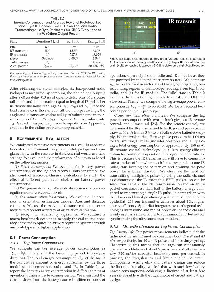
operation; separately for the radio and IR modules as theyare powered by independent battery sources. We computeIbat as total current in each state of the tag by integrating cor-responding regions of oscilloscope readings from Fig. 6a forradio, and (b) for IR module. The ‘idle’ state in Table 2includes the transitioning periods from ‘sleep’to ON andvice-versa. Finally, we compute the tag average power con-
sumption as Pavg ¼ Etott, to be 80.486 mW for a 1 second bea-
coning period in our prototype.Comparison with other prototypes. We compare the tag
power consumption with two technologies; an IR remotecontrol, and ultrasound [26]. For the remote-control, wedetermined the IR pulse period to be 10 ms and peak currentdraw at 50 mA from a 3 V (two alkaline AAA batteries) sup-ply. We interpolate the effective pulse-period to be 1.04 msfor transmitting 13 bytes (includes preamble and ID), yield-ing a total energy consumption of approximately 150 mW.IR remote control technology is a less energy-efficientoption for continuous operation in recognition applications.This is because the IR transmission will have to communi-cate a packet of bits where each bit corresponds to one IRpulse, thus keeping the battery on and draining the peakpower for a longer duration. We eliminate the need fortransmitting multiple IR pulses by using the radio channelto communicate the ID through a RFID packet. As can beseen from Table 2, the RF transmission to send an entirepacket consumes less than half of the battery energy com-pared to transmitting a single IR pulse. In comparison withthe ultrasound based positioning system implementation inSpiderBat [26], our transmitter achieves about 1.5x higherenergy efficiency. SpiderBat integrates two orthogonal tech-nologies (ultrasound and radio), however, the radio channelis only used as a side-channel to communicate ID but not forsynchronizing the ultrasound transmissions.
5.1.2 Micro-Benchmarks for Tag Power Consumption
Tag Battery Life. Our power measurements indicate that theradio module and IR module consume about 33 mW and 49mW respectively, for 10 ms IR pulse and 1 sec duty-cycling.Theoretically, this means that the tags can continuouslyoperate for a lifetime of about 9 years on a 9 V alkaline bat-tery (520 mAhrs capacity) beaconing once per second. Inpractice, the irregularities and limitations in the circuit(components, wiring etc.) and battery design can reducethe lifetime. In reality, we feel that with such low batterypower consumptions, achieving a lifetime of at least fewyears is possible with the right choice of circuit and batterydesign.
TABLE 2Energy Consumption and Average Power of Prototype Tag
for a 10 ms IR Beacon (Two LEDs on Tag) and RadioTransmitting a 12 Byte Packet at 250 KBPS Every 1sec at
1 mW (0dbm) Output Power
State Duration d [ms] Ibat [mA] Energy [mJ]
idle 800 2.95 7.08RF transmit 500 15.52 23.28IR transmit 10 527.8 48.029sleep 998,688 0.0007 2.097Total energy Etot 80.486Avg. power Pavg ¼ Etot=t 80.486 mW
Energy ¼ VbatIbatd, where Vbat ¼ 3V for radio module and 8.1V for IR, t ¼1 s;these also include the microprocessor’s consumption since we account for thetotal battery drain.
Fig. 6. (a) Tag’s radio module battery drain (voltage reading is across a1 V resistor on an analog oscilloscope). (b) Tag’s IR module batterydrain (voltage reading is across a 3.9 V resistor on a digital oscilloscope.
ASHOK ET AL.: WHAT AM I LOOKING AT? LOW-POWER RADIO-OPTICAL BEACONS FOR IN-VIEW RECOGNITION ON SMART-GLASS 3191
IR Pulse Length. A large IR pulse length in our systemimplies more radiated IR energy. Increasing IR pulse lengthenables to increase the angular and/or distance range, buttrades-off with the increase in battery power consumption.In Fig. 7a we plot the measured power consumption versusthe distance range (maximum distance of recognition) in oursystem, for different IR pulse duration choices. As can beseen from Fig. 7a, a 10 ms pulse can achieve only a 3 m range.However, we believe that this range still useful for manyshort distance interactive applications on the smart-glasses;for example, interacting with posters in a conference or arti-facts in amuseum, searching for items in a shelf in a store.
Transmitter Beaconing Period. In Fig. 7b we plot the trans-mitter power consumption for different beaconing periodst. The plot indicates that, for a 10 ms pulse, increasing thebeaconing period (less beacons per unit time) is increased to5 seconds considerably saves battery power. However,power savings is less pronounced when increasing the IRpulse length to 500 ms. We learn from Fig. 7b that the batterypower usage monotonically increases with increase in num-ber of beacons transmitted per unit time.
5.1.3 Receiver Power Consumption
The power consumption at the receiver includes that of theradio receiver and IR module. Table 3 compares the averagepower consumption of our receiver prototype with otherexisting technologies for positioning; ultrasound (US) andcamera. Overall, we observe that our design can helpachieve 2.5� more efficient on battery consumption on thereceiver compared to other approaches using competitivetechnologies. Based on our measurements, the battery life(of a 3 V alkaline AA battery) for only the receiver operation
is little less than 2 days. This ensures that it is possible tooperate the smart-glass receiver in an always-ON mode forabout two days without powering OFF.
5.1.4 Discussion
Battery power usage optimization is key to any mobile sys-tem. In this paper, we have focused primarily on optimizingthe battery power consumption of the tags, as we envisionan environment where the tags are attached to mobileobjects. We consider that the primary power source for a tagis from a battery on the mobile object and that it may not bepossible to periodically recharge the battery on such objects.For the receiver, we take an optimistic approach and believethat a wearable device, such as the smart-glass, can typicallybe switched-ON on a need-to-use basis and can be rechargedperiodically. We believe that through strategical techniquessuch as conserved usage of tag and/or receiver for powersavings is possible to further reduce power consumption. Inthis paper, we primarily emphasize the possibility of signifi-cant power savings for long-duration operations through theradio-synchronized IR signaling, enabling to operate thetags and receiver at much lower battery drain than otherstrong candidate approaches such as vision.
5.2 Recognition Accuracy
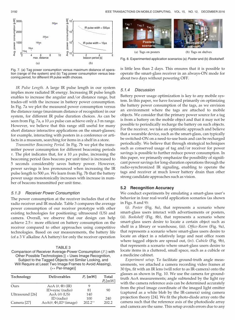
We conduct experiments by emulating a smart-glass user’sbehavior in four real-world application scenarios (as shownin Figs. 8 and 9):
(i). Poster (Fig. 8a), that represents a scenario wheresmart-glass users interact with advertisements or posters,(ii). Bookshelf (Fig. 8b), that represents a scenario wheresmart-glass users desire to locate a certain object such asshelf in a library or warehouse, (iii). Office-Room (Fig. 9a),that represents a scenario where smart-glass users desire tolocate an object in a relatively large and neat office roomwhere tagged objects are spread out, (iv). Cubicle (Fig. 9b),that represents a scenario where smart-glass users desire tolocate items in a cluttered, small space, such as a cubicle ora medicine cabinet.
Experiment setup. To facilitate ground-truth angle meas-urements, we attached a camera recording video frames at30 fps, fit with an IR lens (will refer to as IR-camera) onto theglasses as shown in Fig. 10. We use the camera for ground-truth AoA measurements; angle subtended by the light raywith the camera reference axis can be determined accuratelyfrom the pixel image coordinate of the imaged light emitter(captured as a white blob by the IR-camera) using cameraprojection theory [24]. We fit the photo-diode array onto thecamera such that the reference axis of the photodiode arrayand camera are the same. This setup avoids errors due to any
Fig. 7. (a) Tag power consumption versus maximum distance of opera-tion (range of the system) and (b) Tag power consumption versus bea-coning period, for different IR pulse width choices.
TABLE 3Comparison of Receiver Average-Power Consumption (Pr) with
Other Possible Technologies [( � Uses Image Recognition,Subject to the Tagged Objects not Similar Looking, and
Will Require at Least Two Image Frames to Avoid Aliasing),(�� Per-Image)]
Technology Deliverables PrPr [mW] TotalPrPr[mW]
Ours AoA (u;F) (IR) 9ID+sync (radio) 81 90
Ultrasound [26] AoA (u) (US) 140ID (radio) 100 240
Camera [27] AoA(u;F),ID�(image) 202.2�� 202.2
Fig. 8. Experimented application scenarios (a) Poster and (b) Bookshelf.
3192 IEEE TRANSACTIONS ON MOBILE COMPUTING, VOL. 15, NO. 12, DECEMBER 2016
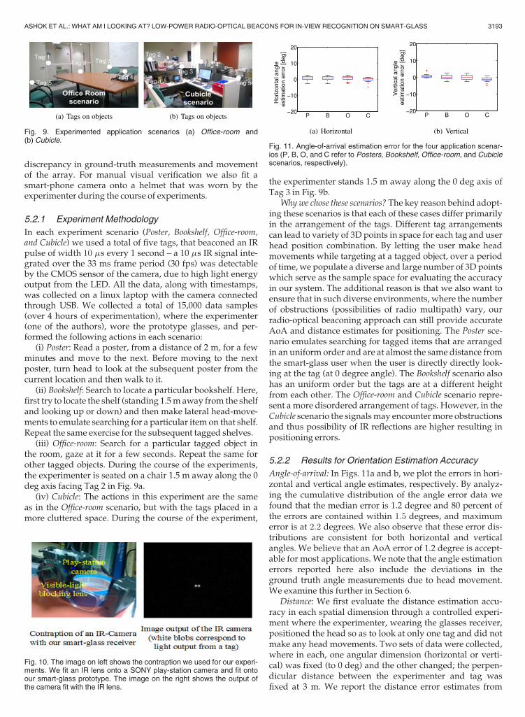
discrepancy in ground-truth measurements and movementof the array. For manual visual verification we also fit asmart-phone camera onto a helmet that was worn by theexperimenter during the course of experiments.
5.2.1 Experiment Methodology
In each experiment scenario (Poster, Bookshelf, Office-room,and Cubicle) we used a total of five tags, that beaconed an IRpulse of width 10 ms every 1 second – a 10 ms IR signal inte-grated over the 33 ms frame period (30 fps) was detectableby the CMOS sensor of the camera, due to high light energyoutput from the LED. All the data, along with timestamps,was collected on a linux laptop with the camera connectedthrough USB. We collected a total of 15,000 data samples(over 4 hours of experimentation), where the experimenter(one of the authors), wore the prototype glasses, and per-formed the following actions in each scenario:
(i) Poster: Read a poster, from a distance of 2 m, for a fewminutes and move to the next. Before moving to the nextposter, turn head to look at the subsequent poster from thecurrent location and then walk to it.
(ii) Bookshelf: Search to locate a particular bookshelf. Here,first try to locate the shelf (standing 1.5m away from the shelfand looking up or down) and then make lateral head-move-ments to emulate searching for a particular item on that shelf.Repeat the same exercise for the subsequent tagged shelves.
(iii) Office-room: Search for a particular tagged object inthe room, gaze at it for a few seconds. Repeat the same forother tagged objects. During the course of the experiments,the experimenter is seated on a chair 1.5 m away along the 0deg axis facing Tag 2 in Fig. 9a.
(iv) Cubicle: The actions in this experiment are the sameas in the Office-room scenario, but with the tags placed in amore cluttered space. During the course of the experiment,
the experimenter stands 1.5 m away along the 0 deg axis ofTag 3 in Fig. 9b.
Whywe chose these scenarios? The key reason behind adopt-ing these scenarios is that each of these cases differ primarilyin the arrangement of the tags. Different tag arrangementscan lead to variety of 3D points in space for each tag and userhead position combination. By letting the user make headmovements while targeting at a tagged object, over a periodof time, we populate a diverse and large number of 3D pointswhich serve as the sample space for evaluating the accuracyin our system. The additional reason is that we also want toensure that in such diverse environments, where the numberof obstructions (possibilities of radio multipath) vary, ourradio-optical beaconing approach can still provide accurateAoA and distance estimates for positioning. The Poster sce-nario emulates searching for tagged items that are arrangedin an uniform order and are at almost the same distance fromthe smart-glass user when the user is directly directly look-ing at the tag (at 0 degree angle). The Bookshelf scenario alsohas an uniform order but the tags are at a different heightfrom each other. The Office-room and Cubicle scenario repre-sent a more disordered arrangement of tags. However, in theCubicle scenario the signalsmay encountermore obstructionsand thus possibility of IR reflections are higher resulting inpositioning errors.
5.2.2 Results for Orientation Estimation Accuracy
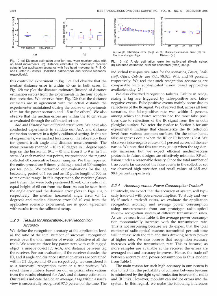
Angle-of-arrival: In Figs. 11a and b, we plot the errors in hori-zontal and vertical angle estimates, respectively. By analyz-ing the cumulative distribution of the angle error data wefound that the median error is 1.2 degree and 80 percent ofthe errors are contained within 1:5 degrees, and maximumerror is at 2:2 degrees. We also observe that these error dis-tributions are consistent for both horizontal and verticalangles. We believe that an AoA error of 1.2 degree is accept-able for most applications. We note that the angle estimationerrors reported here also include the deviations in theground truth angle measurements due to head movement.We examine this further in Section 6.
Distance: We first evaluate the distance estimation accu-racy in each spatial dimension through a controlled experi-ment where the experimenter, wearing the glasses receiver,positioned the head so as to look at only one tag and did notmake any head movements. Two sets of data were collected,where in each, one angular dimension (horizontal or verti-cal) was fixed (to 0 deg) and the other changed; the perpen-dicular distance between the experimenter and tag wasfixed at 3 m. We report the distance error estimates from
Fig. 9. Experimented application scenarios (a) Office-room and(b) Cubicle.
Fig. 10. The image on left shows the contraption we used for our experi-ments. We fit an IR lens onto a SONY play-station camera and fit ontoour smart-glass prototype. The image on the right shows the output ofthe camera fit with the IR lens.
Fig. 11. Angle-of-arrival estimation error for the four application scenar-ios (P, B, O, and C refer to Posters, Bookshelf, Office-room, and Cubiclescenarios, respectively).
ASHOK ET AL.: WHAT AM I LOOKING AT? LOW-POWER RADIO-OPTICAL BEACONS FOR IN-VIEW RECOGNITION ON SMART-GLASS 3193
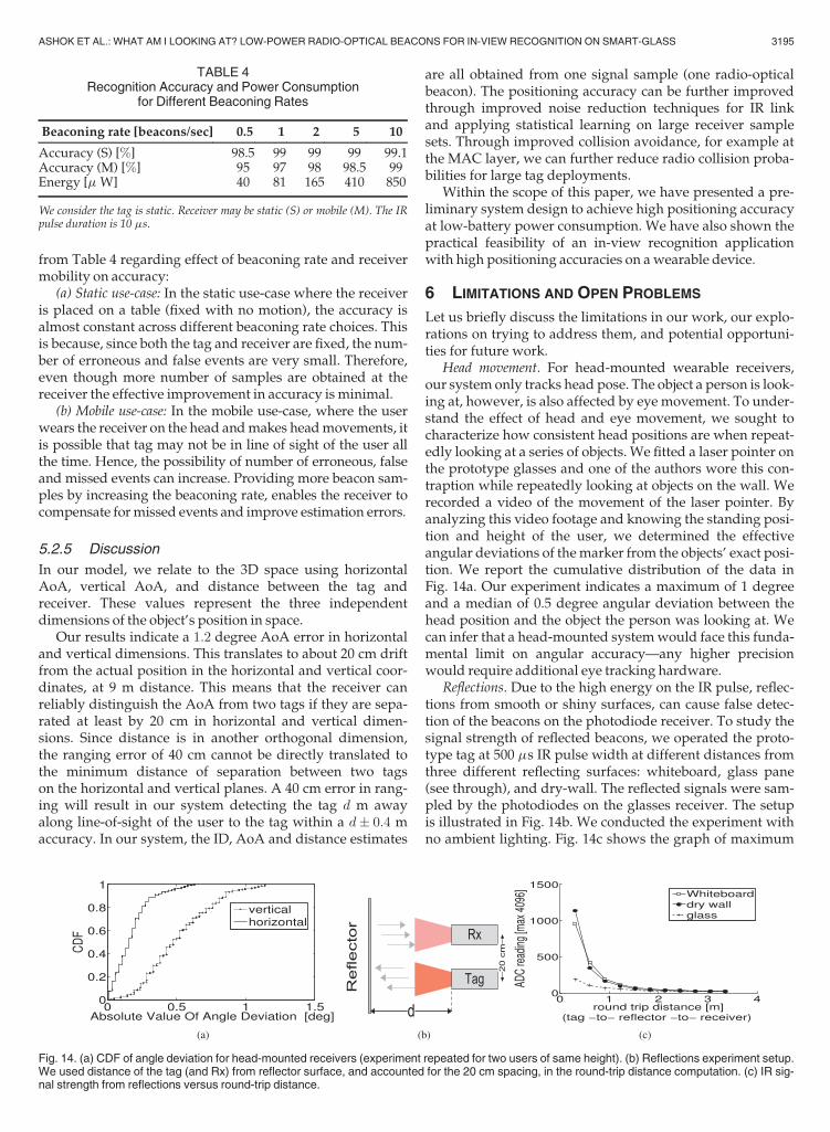
this controlled experiment in Fig. 12a and observe that themedian distance error is within 40 cm in both cases. InFig. 12b we plot the distance estimates (instead of distanceestimation errors) from the experiments in the four applica-tion scenarios. We observe from Fig. 12b that the distanceestimates are in agreement with the actual distance theexperimenter maintained during the course of experiments(2 m for the poster scenario and 1.5 m for others). We alsoobserve that the median errors are within the 40 cm valueas evaluated through the calibrated set-up.
AoA and Distance from calibrated experiments: We have alsoconducted experiments to validate our AoA and distanceestimation accuracy in a tightly calibrated setting. In this setof experiments, we marked locations on the laboratory floorfor ground-truth angle and distance measurements. Themeasurements spanned �10 to 10 degree in 1 degree spac-ings on the horizontal (uver ¼ 0) and from 5 to 9 m in 1 msteps. At each marked test points, we positioned the tag andcollected 60 consecutive beacon samples. We then repeatedthe entire procedure 5 times, yielding a total of 300 samplesper test point. We performed our evaluations for the tagbeaconing period of 1 sec and an IR pulse length of 500 msto maximize range. In this experiment, the receiver glassesand transmitter were both positioned (fixed) on a crate at anequal height of 60 cm from the floor. As can be seen fromthe angle error and the distance error plots in Figs. 13a, brespectively, the median horizontal angle error (of 1:2degrees) and median distance error (of 40 cm) from theapplication scenario experiment, are in good agreementwith results from the calibrated setup.
5.2.3 Results for Application-Level Recognition
Accuracy
We define the recognition accuracy at the application levelas the ratio of the total number of successful recognitionevents over the total number of events, collective of all thetrials. We associate three key parameters with each taggedobject: a unique object ID, AoA, and distance between tagthe receiver. For our evaluation, if the receiver decodes theID, and if angle and distance estimation errors are containedwithin 2.2 degree and 40 cm respectively, we considered itas a successful recognition event or a true-positive. Weselect these numbers based on our empirical observationsfrom the results obtained for AoA and distance estimation.Our results indicate that, on an average, a tag within a user’sview is successfully recognized 97.5 percent of the time. The
individual true-positive rates for the scenarios, Poster, Book-shelf, Office, Cubicle, are 97.1, 98.025, 97.5, and 98 percent,respectively. We feel that such recognition accuracies arecomparable with sophisticated vision based approachesavailable today [25].
We also observed recognition failures. Failure in recog-nizing a tag are triggered by false-positive and false-negative events. False-positive events mainly occur due toreflections of the IR signal. We observed that, across all fourscenarios, the false-positive rate was within 2 percent,among which the Poster scenario had the most false-posi-tives due to reflections of the IR signal from the smoothplexiglas surface. We refer the reader to Section 6 for ourexperimental findings that characterize the IR reflectionlevel from various common surfaces. On the other hand,false-negatives occur when the RF or IR beacon is lost. Weobserve a false-negative rate of 0:5 percent across all the sce-narios. We note that this rate may go up when the tag den-sity increases, but we expect efficient medium-accessprotocols in future designs can effectively minimize RF col-lisions under a reasonable density. Since the total number oftrue events far exceeded the false events in the collective setwe observed high precision and recall values of 96.5 and98.4 percent respectively.
5.2.4 Accuracy versus Power Consumption Tradeoff
Intuitively, we expect that the accuracy of system will typi-cally trade-off with power-consumption. To study and ver-ify if such a tradeoff exists, we evaluate the applicationrecognition accuracy and average power consumptionusing measurements from our prototype radio-opticalin-view recognition system at different transmission rates.As can be seen from Table 4, the average power consump-tion monotonically increases with the transmission rate.This is not surprising because we do expect that the totalnumber of radio-optical beacons transmitted per unit timewill increase with the rate and thus drawing battery powerat higher rate. We also observe that recognition accuracyincreases with the transmission rate. This is because, asmore samples are available at the receiver the errors areaveraged out and accuracy improves. Hence, the trade-offbetween accuracy and power-consumption is thus evidentfrom Table 4.
The main reason for such high accuracy in our system isdue to fact that the probability of collision between beaconsis minimized by the tight synchronization between the radioand IR links. However, mobility can induce errors into thesystem. In this regard, we make the following inferences
Fig. 12. (a) Distance estimation error for head-worn receiver setup withno head movements. (b) Distance estimates for head-worn receiversetup in four application scenarios with free head movements (P, B, O,and C refer to Posters, Bookshelf, Office-room, and Cubicle scenarios,respectively).
Fig. 13. (a) Angle estimation error for calibrated (fixed) setup.(b) Distance estimation error for calibrated (fixed) setup.
3194 IEEE TRANSACTIONS ON MOBILE COMPUTING, VOL. 15, NO. 12, DECEMBER 2016
from Table 4 regarding effect of beaconing rate and receivermobility on accuracy:
(a) Static use-case: In the static use-case where the receiveris placed on a table (fixed with no motion), the accuracy isalmost constant across different beaconing rate choices. Thisis because, since both the tag and receiver are fixed, the num-ber of erroneous and false events are very small. Therefore,even though more number of samples are obtained at thereceiver the effective improvement in accuracy is minimal.
(b) Mobile use-case: In the mobile use-case, where the userwears the receiver on the head andmakes headmovements, itis possible that tag may not be in line of sight of the user allthe time. Hence, the possibility of number of erroneous, falseand missed events can increase. Providing more beacon sam-ples by increasing the beaconing rate, enables the receiver tocompensate formissed events and improve estimation errors.
5.2.5 Discussion
In our model, we relate to the 3D space using horizontalAoA, vertical AoA, and distance between the tag andreceiver. These values represent the three independentdimensions of the object’s position in space.
Our results indicate a 1:2 degree AoA error in horizontaland vertical dimensions. This translates to about 20 cm driftfrom the actual position in the horizontal and vertical coor-dinates, at 9 m distance. This means that the receiver canreliably distinguish the AoA from two tags if they are sepa-rated at least by 20 cm in horizontal and vertical dimen-sions. Since distance is in another orthogonal dimension,the ranging error of 40 cm cannot be directly translated tothe minimum distance of separation between two tagson the horizontal and vertical planes. A 40 cm error in rang-ing will result in our system detecting the tag d m awayalong line-of-sight of the user to the tag within a d� 0:4 maccuracy. In our system, the ID, AoA and distance estimates
are all obtained from one signal sample (one radio-opticalbeacon). The positioning accuracy can be further improvedthrough improved noise reduction techniques for IR linkand applying statistical learning on large receiver samplesets. Through improved collision avoidance, for example atthe MAC layer, we can further reduce radio collision proba-bilities for large tag deployments.
Within the scope of this paper, we have presented a pre-liminary system design to achieve high positioning accuracyat low-battery power consumption. We have also shown thepractical feasibility of an in-view recognition applicationwith high positioning accuracies on awearable device.
6 LIMITATIONS AND OPEN PROBLEMS
Let us briefly discuss the limitations in our work, our explo-rations on trying to address them, and potential opportuni-ties for future work.
Head movement. For head-mounted wearable receivers,our system only tracks head pose. The object a person is look-ing at, however, is also affected by eye movement. To under-stand the effect of head and eye movement, we sought tocharacterize how consistent head positions are when repeat-edly looking at a series of objects. We fitted a laser pointer onthe prototype glasses and one of the authors wore this con-traption while repeatedly looking at objects on the wall. Werecorded a video of the movement of the laser pointer. Byanalyzing this video footage and knowing the standing posi-tion and height of the user, we determined the effectiveangular deviations of themarker from the objects’ exact posi-tion. We report the cumulative distribution of the data inFig. 14a. Our experiment indicates a maximum of 1 degreeand a median of 0.5 degree angular deviation between thehead position and the object the person was looking at. Wecan infer that a head-mounted systemwould face this funda-mental limit on angular accuracy—any higher precisionwould require additional eye tracking hardware.
Reflections. Due to the high energy on the IR pulse, reflec-tions from smooth or shiny surfaces, can cause false detec-tion of the beacons on the photodiode receiver. To study thesignal strength of reflected beacons, we operated the proto-type tag at 500 ms IR pulse width at different distances fromthree different reflecting surfaces: whiteboard, glass pane(see through), and dry-wall. The reflected signals were sam-pled by the photodiodes on the glasses receiver. The setupis illustrated in Fig. 14b. We conducted the experiment withno ambient lighting. Fig. 14c shows the graph of maximum
TABLE 4Recognition Accuracy and Power Consumption
for Different Beaconing Rates
Beaconing rate [beacons/sec] 0.5 1 2 5 10
Accuracy (S) [%] 98.5 99 99 99 99.1Accuracy (M) [%] 95 97 98 98.5 99Energy [mW] 40 81 165 410 850
We consider the tag is static. Receiver may be static (S) or mobile (M). The IRpulse duration is 10 ms.
Fig. 14. (a) CDF of angle deviation for head-mounted receivers (experiment repeated for two users of same height). (b) Reflections experiment setup.We used distance of the tag (and Rx) from reflector surface, and accounted for the 20 cm spacing, in the round-trip distance computation. (c) IR sig-nal strength from reflections versus round-trip distance.
ASHOK ET AL.: WHAT AM I LOOKING AT? LOW-POWER RADIO-OPTICAL BEACONS FOR IN-VIEW RECOGNITION ON SMART-GLASS 3195
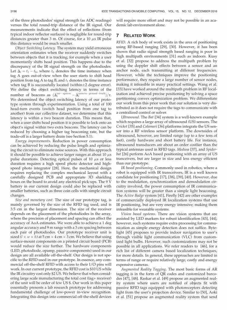
of the three photodiodes’ signal strength (as ADC readings)versus the total round-trip distance of the IR signal. Ourmeasurements indicate that the effect of reflections (fromtypical indoor reflector surfaces) is negligible for round-tripdistances greater than 3 m. Of course, for a 10 ms IR pulsethis distance would be much smaller.
Object Switching Latency. The system may yield erroneousorientation estimates when the receiver suddenly switchesbetween objects that it is tracking; for example when a usermomentarily shifts head position. This happens due to thediscrepancy of the IR signal strength on the photodiodes.Let Dt ¼ t1 � t0, where t0 denotes the time instance whentag A goes out-of-view when the user starts to shift headposition from tag A to tag B, and t1 denotes the time instancewhen tag B is successfully located (within�2 degree error).We define the object switching latency in terms of the
number of beacons as ðDour�systemt � Dcamera�ground�truth
t Þ=t.We determined the object switching latency of our proto-type system through experimentation. Using a total of 100head-turn events (switch head position from one tag toanother) from our collective dataset, we determine that thislatency is within a two beacon duration. This means that,when a user shifts head position it is possible to lock onto anobject’s signal within two extra beacons. The latency can bereduced by choosing a higher tag beaconing rate, but thetrade-off is a larger battery drain (see Section 5.1).
Energy improvements. Reduction in power consumptioncan be achieved by reducing the pulse length and optimiz-ing the circuit to eliminate noise sources. With this approachit should be possible to achieve larger ranges at about 10 mspulse durations. Detecting optical pulses of 10 ms or lessduration requires a high speed photo detector and high-speed photo integrator [28]. Here, the mechanical designrequires replacing the complex mechanical layout with acarefully designed PCB and appropriate 3D shieldingboxes on the board to avoid any electrical pick-ups. The 9 Vbattery in our current design could also be replaced withsmaller batteries, such as three coin cells with simple circuitchanges.
Size and monetary cost. The size of our prototype tag, ismainly governed by the size of the RFID tag used, and is3.5 cm in the largest dimension. The size of the receiverdepends on the placement of the photodiodes in the array,where the precision of placement and spacing can affect theaccuracy of AoA estimates. We were able to achieve a 1 degangular accuracy and 9m rangewith a 3 cm spacing betweeneach pair of photodiodes. Our prototype receiver unit issized (l� w� h) at 5 cm� 4 cm� 3 cm.We believe that usingsurface-mount components on a printed circuit board (PCB)would reduce the size further. The hardware components(LED, photodiode, opamp, passive components) used in ourdesign are all available off-the-shelf. Our design is not spe-cific to the RFID used in our prototype. In essence, any com-mercial off-the-shelf RFID with access to their I/O pins willwork. In our current prototype, the RFID cost is $10 USwhilethe IR circuitry cost only $2 US.We believe that when consid-ering large scale manufacturing the total cost (tag+ receiver)of the unit will be order of few US $. Our work in this paperessentially presents a lab research prototype for addressingfundamental challenge of low-power in-view recognition.Integrating this design into commercial off-the-shelf devices
will require more effort and may not be possible in an aca-demic lab environment alone.
7 RELATED WORK
RFID. A rich body of work exists in the area of positioningusing RF-based ranging [29], [30]. However, it has beenshown that radio signal strength based ranging is poor inhigh multipath environments [31] such as indoors. Kusyet al. [32] propose to address the multipath problem byusing the doppler shift effects between a sensor and ananchor node, each transmitting at different frequencies.However, while the techniques improve the positioningperformance, they require a large number of sensor nodes,making it infeasible in many practical settings. Wang et al.[33] have worked around the multipath problem in RF local-ization and achieved precise positioning by solving a spacepartitioning convex optimization problem. We differentiateour work from this prior work that our solution is very dis-tributed as it does not require the tags to communicate witha centralized control or solver.
Ultrasound. The Bat [34] system is a well-known examplewhich requires a large array of ultrasound (US) sensors. TheCricket [35] and Calamari [36] platforms integrate the US sen-sor into a RF wireless sensor platform. The downsides ofultrasound, however, are limited range (up to a few tens offeet), costly hardware and short battery life. For instance,ultrasound transducers are about an order costlier than thetypical antennas used in RFID tags. Medusa [37], and Spider-bat [26] perform AoA based positioning with an array of UStranceivers, but are larger in size and less energy efficientthan our prototype.
IR based positioning. Commonly used in robotics, where arobot is equipped with IR transceivers, IR is a well knowncandidate for positioning [17], [38], [39], [40]. However, dueto the modulation, synchronization and demodulation cir-cuitry involved, the power consumption of IR communica-tion systems will be greater than a simple light beaconing.The Active Badge system [41], Firefly [42] are other examplesof commercially deployed IR localization systems that useIR positioning, but are very energy intensive; making theminfeasible for wearable systems.
Vision based systems. There are vision systems that areassisted by LED markers for robust identification [43], [44],however, such systems require extra processing for commu-nication as simple energy detection does not suffice. Byte-light [45] proposes to provide indoor navigation to user’sthrough visible light communication (VLC) from custom-ized light bulbs. However, such customizations may not bepossible in all applications. We refer readers to [46], for arich list of different camera based localization techniques,for more details. In general, these approaches are limited interms of range or require relatively large, costly and energyexpensive cameras.
Augmented Reality Tagging. The most basic forms of ARtagging is in the form of QR codes and customized barco-des [47], [48]. Raskar et al. [49] propose an augmented real-ity system where users are notified of objects fit withpassive RFID tags equipped with photoreceptors detectinglight from the user’s projection device. Similar to [50], Aokiet al. [51] propose an augmented reality system that send
3196 IEEE TRANSACTIONS ON MOBILE COMPUTING, VOL. 15, NO. 12, DECEMBER 2016

context information, such as, location and ID, through IRdevices to a camera feed – for processing or communication.The RFID readers, mobile projectors, and cameras are costlyas well as energy intensive.
We note that our proposed synchronization approach tohybrid radio-optical beaconing significantly differs fromexisting multi-radio optimization techniques such as low-power wake-up [52] or intelligent switching between radioswith different energy profiles [53], [54]. Indeed, existingwake-up techniques are complementary in that the RF linkcan also be used to wake up the IR transmitter when areceiver is detected in the IR range.
8 CONCLUSIONS
In this paper, we argue that a hybrid radio-optical beacon-ing approach can facilitate accurate and low-power recogni-tion of objects within a user’s view. Our approach leveragesthe high directionality characteristic of an infrared link forprecise angle and distance estimation, and the low powernature of a radio link for synchronization and communica-tion. The novelty of this design lies in the usage of a radiolink to synchronize the infrared beacons such that veryshort high-energy infrared pulses could be used, whichresults in much reduced energy consumption, a simplifiedreceiver design, and small hardware size. We prototypedthe system by designing radio-optical tags and a wearablereceiver, in the form of an object tracking eye-glasses. Ourprototype receiver locates the infrared tags with an angularaccuracy of 1:2 degree on the horizontal and vertical dimen-sions, and up to 9 m distance at very low battery power con-sumption, supporting tag battery life of the order of years.More importantly, the receiver is able to successfully recog-nize objects more than 97 percent of the time. We believethat with such accurate in-view recognition and long life-time, our system can expand support from smart-glasses toalso a wide range of applications in the wearable computingspectrum.
The main goal of the problem addressed in this paperwas to achieve a low-power framework for precise recognitionof contexts in a user’s view-space. We designed a systemwhere objects or contexts are tagged with transmitters thatare used as active landmarks for recognition on a wearabledevice. We clearly understand that it not feasible to tagevery object/context in the world and the deployment den-sity of the tags will depend on the application. We feel thispaper, through a novel design, contributes a step forward inlow-power wearables’ technology by designing low-poweractive landmarks or tags that assist recognition using wear-able devices and that are operable for years.
ACKNOWLEDGMENTS
This project has been funded by the US NSF under grantCNS 1065463. Ashwin Ashok and Chenren Xu are corre-sponding authors.
REFERENCES
[1] (2013). Google Glass [Online]. Available: http://www.google.com/glass/start/
[2] (2008). Recon jet [Online]. Available: http://www.reconinstru-ments.com/products/jet/
[3] Meta [Online]. Available: https://www.spaceglasses.com/[4] Microsoft Hololens [Online]. Available: https://www.microsoft.
com/microsoft-hololens/en-us[5] A. D. Cheok, X. Yang, Z. Z. Ying, M. Billinghurst, and H. Kato,
“Touch-space: Mixed reality game space based on ubiquitous, tan-gible, and social computing,” Personal Ubiquitous Comput., vol. 6,nos. 5–6, pp. 430–442, 2002.
[6] Occulus vr – virtual reality headset for 3D gaming [Online]. Avail-able: http://www.oculus.com/
[7] S. Rallapalli, A. Ganesan, K. Chintalapudi, V. Padmanabhan, andL. Qiu, “Enabling physical analytics in retail stores using smartglasses,” in Proc. 20th Annu. Int. Conf. Mobile Comput. Netw., 2014,pp. 115–126.
[8] (2013). Wikitude: The world’s leading augmented reality SDK[Online]. Available: http://www.wikitude.com/
[9] H. Wang, S. Sen, A. Elgohary, M. Farid, M. Youssef, and R. R.Choudhury, “No need to war-drive: Unsupervised indoor local-ization,” in Proc. 10th Int. Conf. Mobile Syst., Appl. Serv., 2012,pp. 197–210.
[10] (2013). Inside Microsoft Research: Making purchases with zeroeffort [Online]. Available: http://tinyurl.com/bkjt9js
[11] L. Yang, Y. Chen, X.-Y. Li, C. Xiao, M. Li, and Y. Liu, “Tagoram:Real-time tracking of mobile RFID tags to high precision usingcots devices,” in Proc. 20th Annu. Int. Conf. Mobile Comput. Net-work., 2014, pp. 237–248.
[12] F. Adib, Z. Kabelac, D. Katabi, and R. C. Miller, “3D tracking viabody radio reflections,” in Proc. 11th USENIX Conf. Netw. Syst.Des. Implementation, 2014, pp. 317–329.
[13] L. Zhang, X.-Y. Li, W. Huang, K. Liu, S. Zong, X. Jian, P. Feng,T. Jung, and Y. Liu, “It starts with igaze: Visual attention drivennetworking with smart glasses, “in Proc. 20th Annu. Int. Conf.Mobile Comput. Netw., 2014, pp. 91–102.
[14] A. Mayberry, P. Hu, B. Marlin, C. Salthouse, and D. Ganesan,“Ishadow: Design of a wearable, real-time mobile gazetracker,” in Proc. 12th Annu. Int. Conf. Mobile Syst. Appl. Serv.,2014, pp. 82–94.
[15] Infrared data association [Online]. Available: http://irdajp.info/[16] Giga-ir high speed opto-communication [Online]. Available:
http://www.google.com/glass/start/[17] L. Korba, S. Elgazzar, and T. Welch, “Active infrared sensors for
mobile robots,” IEEE Trans. Instrum. Measure., vol. 43, no. 2,pp. 283–287, Apr. 1994.
[18] G. Benet, F. Blanes, J. E Sim�o, and P. P�erez, “Map building usinginfrared sensors in mobile robots,” in New Developments in RoboticsResearch? Commack, NY, USA: Nova, 2006.
[19] B. Firner, C. Xu, R. Howard, and Y. Zhang, “Multiple receiverstrategies for minimizing packet loss in dense sensor networks,”in Proc. 11th ACM Int. Symp. Mobile Ad Hoc Netw. Comput., 2010,pp. 211–220.
[20] C. Yuodelis and A. Hendrickson, “A qualitative and quantitativeanalysis of the human fovea during development,” Vis. Res.,vol. 26, no. 6, pp. 847–855, 1986.
[21] A. Ashok, C. Xu, T. Vu, M. Gruteser, R. Howard, Y. Zhang,N. Mandayam, W. Yuan, and K. Dana, “Bifocus: Using radio-optical beacons for an augmented reality search application,”in Proc. 11th Annu. Int. Conf. Mobile Syst. Appl. Serv., 2013, pp. 507–508.
[22] TSAL 5300 [Online]. Available: http://www.led-eshop.de/PDF/5mm/VISHAY_TSAL5300.pdf
[23] BPV10NF [Online]. Available: http://www.vishay.com/docs/81503/bp10nf.pdf
[24] R. I. Hartley and A. Zisserman, Multiple View Geometry in Com-puter Vision, 2nd ed. Cambridge, U.K.: Cambridge Univ. Press,2004.
[25] New object recognition algorithm learns on the fly [Online].Available: http://www.gizmag.com/learning-object-recognition-algorithm-byu/30512/
[26] G. Oberholzer, P. Sommer, and R. Wattenhofer, “Spiderbat: Aug-menting wireless sensor networks with distance and angleinformation,” in Proc. 13th Annu. Int. Conf. Mobile Syst. Appl. Serv.,2011, pp. 241–256.
[27] R. LiKamWa, B. Priyantha, M. Philipose, L. Zhong, and P. Bahl,“Energy characterization and optimization of image sensingtoward continuous mobile vision,” in Proc. 11th Annu. Int. Conf.Mobile Syst. Appl. Serv., 2013, pp. 69–82.
[28] J. Williams, 1991. Linear Technologies: High Speed AmplifierTechniques, A Designers Companion for Wideband Circuitry,http://cds.linear.com/docs/en/application-note/an47fa.pdf
ASHOK ET AL.: WHAT AM I LOOKING AT? LOW-POWER RADIO-OPTICAL BEACONS FOR IN-VIEW RECOGNITION ON SMART-GLASS 3197
[29] P. Bahl and V. N. Padmanabhan, “RADAR: An in-building RF-based user location and tracking system,” in IEEE Infocom, vol. 2,pp. 775–784, 2000.
[30] K. Whitehouse, C. Karlof, and D. Culler, “A practical evaluation ofradio signal strength for ranging-based localization,” ACM SIGMO-BILEMobile Comput. Commun. Rev., vol. 11, no. 1, pp. 41–52, 2007.
[31] M. Wattenhofer, “Lost in space or positioning in sensornetworks,” in REALWSN, 2005.
[32] B. Kusy, A. Ledeczi, and X. Koutsoukos, “Tracking mobile nodesusing rf doppler shifts,” in Proc. 5th Int. Conf. Embedded Netw. Sen-sor Syst., 2007, pp. 29–42.
[33] J. Wang, F. Adib, R. Knepper, D. Katabi, and D. Rus, “RF-com-pass: Robot object manipulation using RFIDs,” in Proc. 19th Annu.Int. Conf. Mobile Comput. Netw., 2013, pp. 3–14.
[34] A. Harter, A. Hopper, P. Steggles, A. Ward, and P. Webster, “Theanatomy of a context-aware application,” in Proc. 5th Annu. ACM/IEEE Int. Conf. Mobile Comput. Netw., 1999, pp. 59–68.
[35] N. B. Priyantha, A. Chakraborty, and H. Balakrishnan, “Thecricket location-support system,” in Proc. 6th Annu. Int. Conf.Mobile Comput. Netw., 2000, pp. 32–43.
[36] A. Woo C. Karlof K. Whitehouse, F. Jiang, and D. Culler, “Sensorfield localization: A deployment and empirical analysis,” in UCBerkeley, Berkeley, CA, Tech. Rep. UCB//CSD-04-1349, 2004.
[37] A. Savvides, C.-C. Han, and Mani B. Strivastava, “Dynamic fine-grained localization in ad-hoc networks of sensors,” in Proc. 7thAnnu. Int. Conf. Mobile Comput. Netw., 2001, pp. 166–179.
[38] E. Brassart, C. Pegard, and M. Mouaddib, “Localization usinginfrared beacons,” Robotica, vol. 18, no. 2, pp. 153–161, 2000.
[39] M. V. Moreno, M. A. Zamora, J. Santa, and A. F. Skarmeta, “Anindoor localization mechanism based on RFID and IR data inambient intelligent environments,” in Proc. 6th Int. Conf. InnovativeMobile Internet Serv. Ubiquitous Comput., 2012, pp. 805–810.
[40] S. Lee and S.-Y. Jung, “Location awareness using angle-of-arrivalbased circular-pd-array for visible light communication,” in Proc.18th Asia-Pac. Conf. Commun., 2012, pp. 480–485.
[41] R. Want, A. Hopper, V. Falc~ao, and J. Gibbons, “The active badgelocation system,” ACM Trans. Inform. Syst., vol. 10, no. 1, pp. 91–102, 1992.
[42] (1999). Firefly motion tracking system user’s guide [Online].Available: http://www.gesturecentral.com/firefly/FireflyUser-Guide.pdf
[43] S. Hijikata, K. Terabayashi, and K. Umeda, “A simple indoor self-localization system using infrared leds,” in Proc. 6th Int. Conf.Netw. Sens. Syst., 2009, pp. 1–7.
[44] News - casio unveils prototype of visible light communicationsystem [Online]. Available: bit.ly/zpfjY1
[45] Bytelight: Indoor location. with light [Online]. Available: http://www.bytelight.com/
[46] R. Mautz and S. Tilch, “Survey of optical indoor positioningsystems,” in Proc. Int. Conf. Indoor Position. Indoor Navigation, 2011,pp. 1–7.
[47] (2009). Artag [Online]. Available: http://www.artag.net/[48] A. Mohan, G. Woo, S. Hiura, Q. Smithwick, and R. Raskar,
“Bokode: Imperceptible visual tags for camera based interactionfrom a distance,” ACM Trans. Graph., New York, NY, USA,vol. 28, no. 3, pp. 98:1–98:8, Jul. 2009, Art. no. 98, Doi: 10.1145/1531326.1531404.
[49] R. Raskar, P. Beardsley, J. V. Baar, Y. Wang, P. Dietz, J. Lee,D. Leigh, and T. Willwacher, “RFIG lamps: Interacting with a self-describing world via photosensing wireless tags and projectors,”in ACM SIGGRAPH, 2004, pp. 406–415.
[50] D. J. Moore, R. Want, B. L. Harrison, A. Gujar, and K. Fishkin,“Implementing phicons: Combining computer vision with infra-red technology for interactive physical icons,” in Proc. 12th Annu.ACM Symp. User Interface Softw. Technol., 1999, pp. 67–68.
[51] H. Aoki and S. Matsushita, “Balloon tag: (In)visible marker whichtells who’s who,” in Proc. 4th IEEE Int. Symp. Wearable Comput.,2000, p. 181.
[52] E. Shih, P. Bahl, and M. J. Sinclair, “Wake on wireless: An eventdriven energy saving strategy for battery operated devices,” inProc. 8th Annu. Int. Conf. Mobile Comput. Netw., 2002, pp. 160–171.
[53] G. Ananthanarayanan and I. Stoica, “Blue-fi: Enhancing wi-fi per-formance using bluetooth signals,” in Proc. 7th Int. Conf. MobileSyst. Appl. Serv., 2009, pp. 249–262.
[54] M. Uddin and T. Nadeem, “A2PSM: Audio assisted wi-fi powersaving mechanism for smart devices,” in Proc. 14th WorkshopMobile Comput. Syst. Appl., 2013.
Ashwin Ashok received the PhD degree in Oct 2014 from the WirelessInformation Network Lab (WINLAB) at Rutgers University under thesupervision of Profs. Marco Gruteser, Narayan Mandayam, and KristinDana. He is a postdoctoral research associate in ECE at Carnegie Mel-lon University (CMU) under the mentorship of Prof. Peter Steenkiste(CMU). He works in collaboration with Dr. Fan Bai (GM labs) and con-ducts research on building cloud computing systems for vehicles. Hisresearch work spans areas in mobile systems and computing, cloudcomputing, visible light and camera communications, vehicular network-ing, computer vision, augmented reality, wearable systems and localiza-tion. His thesis pioneered camera-based communication in mobilecomputing and visible light communication (VLC) through a novel con-cept called visual MIMO. During his doctoral tenure at Rutgers, he wonthe best teaching assistant award and also a research excellence award.He is currently the workshop co-chair for MobiCom 2016 and is alsoco-chairing the workshop on Wearable Systems and Applications(WearSys) at MobiSys 2016. He is an experimentalist and has keeninterests in mobile system design and prototyping, and loves tinkeringwith circuits, Arduino and wearable devices.
Chenren Xu received the BE degree (Highest Hons.) from the Depart-ment of Automation at Shanghai University in 2008, the MS degree fromthe Department of Statistics at Rutgers in 2014, and the PhD degreeunder the guidance of Prof. Yanyong Zhang at WINLAB/Department ofElectrical and Computer Engineering of Rutgers University in 2014. Heis an assistant professor in the School of EECS at Peking University anda member of CECA. His research interests span different aspects ofwireless networks. He is currently researching cross-layer design in theXIA future internet architecture to support and optimize mobility, with aparticular focus on vehicular use cases. He is also interested in buildinghealth-related edge applications involving mobile sensing, ubiquitouscomputing, embedded systems and machine learning, to deploy them inthe wild and benefit people in daily life.
Tam Vu received the BS degree in 2006 from Hanoi University of Tech-nology, Vietnam, and the PhD degree in 2013 from WINLAB and theDepartment of Computer Science, Rutgers University, advised by Prof.Marco Gruteser and Prof. Dipankar Raychaudhuri. He is an assistantprofessor in the Department of Computer Science and Engineering,University of Colorado, Denver. He directs the Mobile and NetworkedSystems (MNS) lab, where he and his team have been working on secu-rity and privacy protections for mobile systems and context services.Collaborating with clinical doctors and and industrial partners, he is alsoleading research efforts to design and develop mobile healthcare sys-tems that help monitor and diagnose sleeping disorders in children.Before that, he worked on various topics in core networking includinginter domain routing, mobile-centric network architecture for future Inter-net, and end-host location privacy protection. He has interdisciplinaryinterests that combine algorithmic and theoretic aspects of computerscience with hardware and software engineering, distributed systemsand wireless communications of computer engineering. He is the recipi-ent of CRC Interdisciplinary Fellowship in 2015. He received the GoogleFaculty Research Award in 2014, and best paper awards in ACM Mobi-Com 2012 and ACM MobiCom 2011. His research also received presscoverage including The Wall Street Journal, National Public Radio(NPR),MIT Technology Review, Yahoo News, among other venues.
Marco Gruteser is a professor of electrical and computer engineeringas well as computer science (by courtesy) at Rutgers University’s Wire-less Information Network Laboratory (WINLAB). He directs research inmobile computing, is a pioneer in the area of location privacy and recog-nized for his work on connected vehicles.
Rich Howard is a research professor at WINLAB, Rutgers University.He was formerly with Bell-Labs research as a director of WirelessResearch.
3198 IEEE TRANSACTIONS ON MOBILE COMPUTING, VOL. 15, NO. 12, DECEMBER 2016
Yanyong Zhang received the BS degree in computer science from theUniversity of Science and Technology of China in 1997 and the PhDdegree in computer science and engineering from Penn State Universityin 2002. She joined the Electrical and Computer Engineering Depart-ment of Rutgers University as an assistant professor in 2002. In 2008,she was promoted to associate professor with tenure, and in 2015, waspromoted to full professor. She is also a member of the Wireless Infor-mation Networking Laboratory (Winlab). During March-July 2009, shewas a visiting scientist at Nokia Research Center Beijing. Dr. Zhang isthe recipient of the US NSF CAREER award. She is currently an associ-ate editor for the IEEE Transactions on Mobile Computing and IEEETransactions on Services Computing. She has served on TPC for manyconferences, including Infocom, ICDCS, DSN, IPSN, etc.
Narayan Mandayam received the BTech (Hons.) degree in 1989 fromthe Indian Institute of Technology, Kharagpur, and the MS and PhDdegrees in 1991 and 1994, respectively, from Rice University, Houston,TX, all in electrical engineering. He is a Distinguished Professor atRutgers University. From 1994 to 1996, he was a research associate atthe Wireless Information Network Laboratory (WINLAB), Dept. of Electri-cal & Computer Engineering, Rutgers University. In September 1996, hejoined the faculty of the ECE department at Rutgers where he becameassociate professor in 2001 and professor in 2003. Currently, he alsoserves as associate director at WINLAB. He was a visiting faculty fellowin the Department of Electrical Engineering, Princeton University, in Fall2002 and a visiting faculty at the Indian Institute of Science in Spring2003.
Wenjia Yuan received the PhD degree from Rutgers University inOct 2014. She is a software engineer with Google in Mountain View,California, USA.
Kristin Dana received the BS degree in 1990 from the Cooper Union(NY, NY), the MS degree from Massachusetts Institute of Technology in1992, and the PhD degree from Columbia University (NY, NY) in 1999.She is an associate professor in the Department of Electrical and Com-puter Engineering at Rutgers, The State University of New Jersey. Herresearch is in computer vision, pattern recognition, machine learning,optics, and computer graphics. She is the inventor of the “texture cam-era” for convenient measurement of reflectance and texture. Dr. Dana isalso a member of Rutgers Center for Cognitive Science, a member ofGraduate Faculty of the Computer Science Department, and an adjunctassistant professor of medicine at UMDNJ, Robert Wood Johnson Medi-cal School. From 1992-1995, she was on the research staff at SarnoffCorporation developing real-time motion estimation algorithms for appli-cations in defense, biomedicine, and entertainment industries. She is therecipient of the General Electric “Faculty of the Future” fellowship in1990, the Sarnoff Corporation Technical Achievement Award in 1994 forthe development of a practical algorithm for the real-time alignment ofvisible and infrared video images, and the 2001 US National ScienceFoundation Career Award for a program investigating surface sciencefor vision and graphics.
" For more information on this or any other computing topic,please visit our Digital Library at www.computer.org/publications/dlib.
ASHOK ET AL.: WHAT AM I LOOKING AT? LOW-POWER RADIO-OPTICAL BEACONS FOR IN-VIEW RECOGNITION ON SMART-GLASS 3199