ieee transactions on services computing, vol. 2, no. 3 ...chechik/pubs/runtime09.pdf · web...
TRANSCRIPT

Runtime Monitoring ofWeb Service Conversations
Jocelyn Simmonds, Yuan Gan, Marsha Chechik, Member, IEEE Computer Society,
Shiva Nejati, Bill O’Farrell, Elena Litani, and Julie Waterhouse
Abstract—For a system of distributed processes, correctness can be ensured by (statically) checking whether their composition
satisfies properties of interest. However, Web services are distributed processes that dynamically discover properties of other Web
services. Since the overall system may not be available statically and since each business process is supposed to be relatively simple,
we propose to use runtime monitoring of conversations between partners as a means of checking behavioral correctness of the entire
Web service system. Specifically, we identify a subset of UML 2.0 Sequence Diagrams as a property specification language and show
that it is sufficiently expressive for capturing safety and liveness properties. By transforming these diagrams to automata, we enable
conformance checking of finite execution traces against the specification. We show how our language can be used to specify the
Specification Property System (SPS) [1]. We describe an implementation of our approach as part of an industrial system. Finally, we
discuss our experience of specifying and monitoring a number of properties from three existing applications.
Index Terms—Nondeterministic finite automata, runtime monitoring, sequence diagrams, temporal logic patterns, Web service
conversations.
Ç
1 INTRODUCTION
RECENT years have seen an emergence of the field of Webservices, which use Service-Oriented Architectures
(SOAs) to dynamically discover and bind to services inorder to increase the flexibility of business interactions.Each service consists of components and can discover othercomponents using published interfaces. An SOA compo-nent can be written in a traditional compiled language suchas JavaTM, or in an XML-centric language such as BPEL [2].An SOA module is made up of multiple SOA components,which are commonly referred to as Web services.
Since each Web service is a relatively simple process,analysis can concentrate on the message exchange betweenpartners—their conversations. For a classical system ofdistributed processes, correctness can be ensured by staticallychecking their composition against properties of interest. Thesame approach has been taken by several researchers in thecontext of Web services as well, e.g., [3], [4], [5], [6], [7]. Whilestatic analysis is very appealing—errors are discovered aheadof time and without the need to exercise the system, thisapproach has several major limitations as follows:
. Web services typically communicate via infinite-length channels, so the problem is decidable onlyunder certain conditions [8].
. Web applications usually interact with Web servicesdeveloped by partners. Partners are only required tomake Web service interfaces public, not the code.
. Realistic Web services exchange many types ofmessages: some synchronous, some asynchronous,and some with acknowledgments and priorities.
. Web services are typically heterogeneous, i.e., eachcomponent can be implemented in a differentprogramming language.
Instead, we concentrate on the dynamic analysis viaruntime monitoring, which tries to ensure the quality of anapplication through the analysis of runtime events. Theseevents can be analyzed online—during the execution of theapplication, or offline—after the execution has been termi-nated. The latter can be used to express free-form queries overall generated events. However, since these queries are notnecessarily known a priori, the runtime data collected mightnot be sufficient to answer the relevant questions; or, on theother extreme, the amount of data collected may becomeexcessive and hard to manage, leading to intractable analysis.Online techniques, on the other hand, monitor predefinedproperties, collecting just those events that are related to theseproperties. While expressing properties beforehand may benontrivial, the collected data are guaranteed to be both smalland sufficient to check these properties; they also serve as anadditional, and very valuable, documentation of the desiredbehavior of the system. Monitoring as the system runs alsoprovides a chance of recovery once a problem has beendetected, e.g., by terminating execution or trying to return to astable state. For these reasons, we use online monitoringtechniques in this paper.
Our goal is, thus, to create an industrial-strength (inpartnership between the University of Toronto and the IBMToronto Lab) online monitoring framework that is nonin-trusive, supports the dynamic discovery of Web services,
IEEE TRANSACTIONS ON SERVICES COMPUTING, VOL. 2, NO. 3, JULY-SEPTEMBER 2009 223
. J. Simmonds and M. Chechik are with the Department of ComputerScience, University of Toronto, 10 King’s College Road, Toronto, ON,M5S 3G4, Canada. E-mail: {jsimmond, chechik}@cs.toronto.edu.
. Y. Gan, B. O’Farrell, E. Litani, and J. Waterhouse are with the IBMToronto Lab, 8200 Warden Ave, Markham, ON, L6G 1C7, Canada.E-mail: {ygan, billo, elitani, juliew}@ca.ibm.com.
. S. Nejati is with the Simula Research Laboratory, PO Box 134, 1325Lysaker, Norway. E-mail: [email protected].
Manuscript received 26 Sept. 2008; revised 17 Dec. 2008; accepted 18 June2009; published online 29 June 2009.For information on obtaining reprints of this article, please send e-mail to:[email protected], and reference IEEECS Log Number TSC-2008-09-0083.Digital Object Identifier no. 10.1109/TSC.2009.16.
1939-1374/09/$25.00 � 2009 IEEE Published by the IEEE Computer Society
Authorized licensed use limited to: The University of Toronto. Downloaded on March 08,2010 at 17:59:46 EST from IEEE Xplore. Restrictions apply.
deals with synchronous and asynchronous communicationand partners implemented in different languages, allowsfor specifying and efficient monitoring of a variety oftemporal behavior, permits recovery strategies (this is notpart of the current paper), and is usable by practitioners.
We also aim to create an industrial-strength language forspecifying temporal behavior that captures the distributed,interactive, and message-driven nature of business pro-cesses. Our language should enable specifying a variety ofproperties and be amenable to efficient runtime monitor-ing, allowing the analysis of orchestrations involvingmultiple partners, from the point of view of the orchestrat-ing service. We believe that such a language should havethe following characteristics:
1. its notation should be visual;2. it should allow the specification of desired temporal
behavior, via sequences of events;3. it should have an explicit emphasis on components
and enable dealing with different types of messageexchange; and
4. it should be able to specify positive and negativescenarios of interaction as well as global properties.These characteristics are necessary for the resultinglanguage to be usable by practitioners.
Having considered a few behavioral graphical languages,such as GIL [9], Time Line Editor [10], Message SequenceCharts (MSCs) [11], and Live Sequence Charts (LSCs) [12],we have chosen UML 2.0 Sequence Diagrams (SDs) [13] asthe basis for our specification language. SDs, used to captureinteractions in the form of message passing between objects,have been widely adopted by industry as a suitablelanguage for describing and documenting scenario-basedrequirement specifications, with additional constraints ex-pressed using the Object Constraint Language (OCL) [14].The other UML 2.0 diagrams did not meet our requirementsfor a specification language: no support for multiple parties(state machines); only allow the specification of simplesequences of events (communication and interaction over-view diagrams); too low-level (activity diagrams); cannot beused to specify behavior (class diagrams).
SDs are a feature-rich language without a formalsemantics. In this paper, we identify a subset of SDs thatis sufficiently expressive for capturing safety and livenessproperties. While liveness properties are not monitorable ingeneral, they can be effectively checked for Web serviceswith finitely terminating behaviors. Specifically, we aim togenerate three types of monitors: accepting individual(existential) negative behaviors that correspond to a viola-tion of safety properties; their dual, accepting universalpositive behavior that corresponds to finite liveness (oncean event occurs, the rest of the events must occur beforetermination); as well as individual positive behaviors thatcan easily be specified in SDs. For the latter type, we do notlook for violations (if a given trace does not correspond to adesired behavior, perhaps others will), but do report whenwe were able to observe their satisfaction.
To enable monitoring, we formalize our subset of SDsusing finite-state automata. Similar approaches to formaliz-ing sequence diagram variants have been previouslyproposed by other researchers, e.g., [15], [16], [17]. Sinceautomata and logic are intimately related, an automata-based
characterization allows us to investigate connections be-tween SDs and temporal logics, and translate SDs toautomata to enable conformance checking of finite executiontraces against their specifications expressed in SDs. We thenshow that this language is sufficiently expressive to capture awide variety of frequently used properties, captured andcatalogued in the Specification Pattern System (SPS) [1]. Thisapproach also gives basis for tool support to enable usablespecification of runtime conversations.
1.1 A Motivating Example
Consider, for example, a Web-based Loan Application (LA)system, distributed as a sample application with the IBM1
WebSphere1 Integration Developer v6.0.2. Users enter loanapplication information (name, taxpayer id, and loanamount) through a Web page, and are eventually informedof the status of their applications. The LA workflow firstchecks if the user’s credit score is valid, and will declinetheir loan request if the user has a bad credit score, i.e., lessthan 750. A credit score is considered valid if it is between300 and 850. If the credit score is good, the workflow thenchecks the loan amount: loans for $50,000 or less areautomatically approved; loans for larger amounts areearmarked for manual approval.
The workflow diagram in Fig. 1a, which is described as aBPEL specification, shows high-level steps that are executedin a loan application system, and Fig. 1b shows an assemblydiagram describing how the main process of the LA systeminvokes its partners, such as CreditCheck (implemented inJava), rule groups (LoanLimit), or human tasks (Follow-UpDeclinedApp, CompleteTheLoan, and Process-TheApplication). Specifically, the CheckCredit activ-ity in Fig. 1a invokes the CreditCheck partner in Fig. 1b,and the conditional activities ScoreEvaluation andAutoApprovalTest invoke the LoanLimit partner. Thepartners in Fig. 1b implement the following functions:CreditCheck uses the taxpayer id to retrieve thecorresponding credit score; the LoanLimit rule groupchecks the credit score and the loan amount. The humantasks CompleteTheLoan, ProcessApplication, andFollowUp follow the application results Approved,ManualApproval, and Declined, respectively.
Since the LA system is a composition of severaldistributed business processes, its correctness depends onthe correctness of its partners and their interactions. Forexample, the system should guarantee that every request iseventually acknowledged and none are lost or blockedindefinitely, or that loans are only given to customers with agood credit score. However, in the provided LA applica-tion, the CreditCheck module assigns a credit score atrandom, without using the customer id, thus, preventingthe overall system from satisfying this property. Table 1shows some properties of the LA system that can beexpressed using our SD subset. For example, P1 and P2 arepossible safety and liveness properties, respectively.
1.2 Organization of the Paper
The rest of this paper is organized as follows: We describesyntax of the subset of UML 2.0 sequence diagrams used forexpressing properties of Web service conversations inSection 2. We describe the semantics of our chosen subset
224 IEEE TRANSACTIONS ON SERVICES COMPUTING, VOL. 2, NO. 3, JULY-SEPTEMBER 2009
Authorized licensed use limited to: The University of Toronto. Downloaded on March 08,2010 at 17:59:46 EST from IEEE Xplore. Restrictions apply.

of SDs and show how to translate it into automata for
runtime monitoring in Section 3. We then show how our
specification language can be used to specify the complete
set of temporal logic property patterns in Section 4. We
describe the implementation of the runtime monitoring
framework in Section 5 and report on the experience using
this framework for three existing Web service systems in
Section 6. After comparing our approach with related work
in Section 7, we conclude the paper in Section 8 with a
summary and an outline of the future research directions.
2 A LANGUAGE FOR SPECIFYING CONVERSATIONS
We choose a subset of UML 2.0 Sequence Diagrams as thelanguage for specifying Web service conversations. Thissubset satisfies the requirements set forth in the previoussection. We formalize this subset in Section 3 and discuss itsexpressive power in Section 4.
Sequence Diagrams are a popular formalism for model-ing behavioral scenarios by describing sequences ofmessages communicated between different objects overtime. An example Sequence Diagram describing a scenarioof the LA system is shown in Fig. 2a. Sequence Diagramshave two dimensions: vertical, which represents time, andhorizontal, which represents objects. Each object is illu-strated by a rectangle with a vertical dashed line, called alifeline. Lifelines are connected by horizontal arrowsdenoting messages that are sent from one object to another,synchronously (solid arrowhead) or asynchronously (openarrowhead). We refer to Sequence Diagrams with thesefeatures as basic. Basic Sequence Diagrams can be aug-mented by a number of operators to capture moresophisticated scenarios. We use the operators describedbelow in our property specification language and refer toour language as SD.
. Compositional operators: Operators parallel (par)and alternatives (alt) are used to compute theintersection and union of two SDs, respectively.The operator loop is used for repeating the scenariodescribed by an SD multiple times, and opt—fordenoting an optional scenario, equivalent to alt withonly one argument.
. Alphabet changing operators: Operators considerand ignore are used for modifying the communicat-ing alphabet of SDs.
. Critical operator: The critical operator is used toensure atomicity of the enclosed sequence.
. Assertion and negation operators: Operators assertand negate allow users to express mandatory andforbidden system scenarios, respectively.
. Interaction use operator: SDs can be shared byreference, using the ref operator. This is a short-hand for copying the contents of the referred SD,where the ref operator occurs, and is a new featurein UML 2.0.
To describe system scenarios, we often need to expresscomplementation of an individual message or a set ofmessages appearing on the same arrow. The negate operatoris unsuitable for complementing sets because it capturesnegative sequences of messages rather than set comple-mentation. Instead, we use the message complementation
SIMMONDS ET AL.: RUNTIME MONITORING OF WEB SERVICE CONVERSATIONS 225
TABLE 1Several Properties of the LA System
Fig. 1. The LA system: (a) workflow describing the high-level steps of theLA system; (b) an assembly diagram describing how the main process ofthe LA system interacts with its partners.
Authorized licensed use limited to: The University of Toronto. Downloaded on March 08,2010 at 17:59:46 EST from IEEE Xplore. Restrictions apply.
operator, originally introduced in the Property SequenceCharts (PSCs) language [18]. We denote the complement ofa message m by :m and define it as the set of all messagesthat is potentially exchanged between objects of the systemexcept for m.
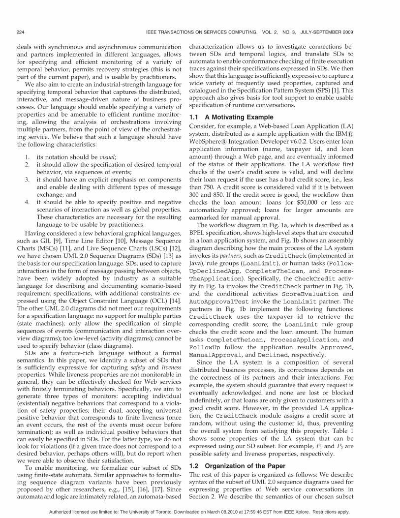
An example of sequence diagram describing a scenarioof the LA system is shown in Fig. 2a. The diagram containsthree objects, MnPs, CtCk, and LnLt. Object MnPs
corresponds to the main workflow of the LA system, andCtCk and LnLt correspond to components CheckCreditand LoanLimit, respectively. The diagram in Fig. 2ashows two alternative scenarios: First, MnPs sends a checkcredit score request, i.e., ckCtSe, to CtCk, and then a checkloan amount request, i.e., ckLnAt, to LnLt. Second, LnLtreceives a check loan amount request from MnPs. Since thecredit score has not yet been checked, LnLt sends a checkcredit score request to CtCk.
Basic Sequence Diagrams, denoted by BasicSDs, are thebuilding blocks of our language. The critical, alphabetchanging, interaction use, assert, and compositional opera-tors, except for par, can be intermixed and applied anynumber of times to BasicSDs. The use of negate and paroperators, however, is restricted to sequence diagrams that
do not use an assert operator. We discuss this assumptionand the rationale behind it in Section 3.6.2 and show inSection 4 that even with this restriction, the resultinglanguage remains very expressive.
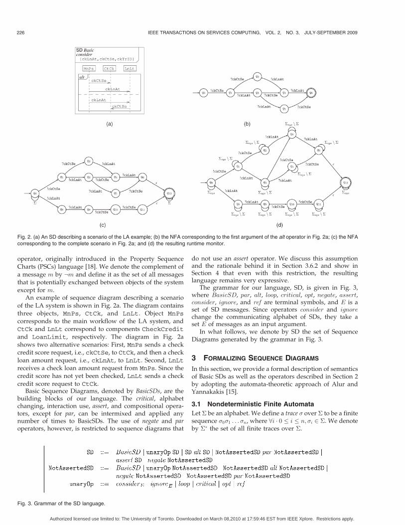
The grammar for our language, SD, is given in Fig. 3,where BasicSD, par, alt, loop, critical, opt, negate, assert,consider, ignore, and ref are terminal symbols, and E is aset of SD messages. Since operators consider and ignorechange the communicating alphabet of SDs, they take aset E of messages as an input argument.
In what follows, we denote by SD the set of SequenceDiagrams generated by the grammar in Fig. 3.
3 FORMALIZING SEQUENCE DIAGRAMS
In this section, we provide a formal description of semanticsof Basic SDs as well as the operators described in Section 2by adopting the automata-theoretic approach of Alur andYannakakis [15].
3.1 Nondeterministic Finite Automata
Let � be an alphabet. We define a trace � over � to be a finitesequence �0�1 . . .�n, where 8i � 0 � i � n; �i 2 �. We denoteby �� the set of all finite traces over �.
226 IEEE TRANSACTIONS ON SERVICES COMPUTING, VOL. 2, NO. 3, JULY-SEPTEMBER 2009
Fig. 2. (a) An SD describing a scenario of the LA example; (b) the NFA corresponding to the first argument of the alt operator in Fig. 2a; (c) the NFA
corresponding to the complete scenario in Fig. 2a; and (d) the resulting runtime monitor.
Fig. 3. Grammar of the SD language.
Authorized licensed use limited to: The University of Toronto. Downloaded on March 08,2010 at 17:59:46 EST from IEEE Xplore. Restrictions apply.
Definition 1 (Projection “# ”). Let �0 � � be an alphabet and� ¼ �0 . . .�n be a trace over �. The projection of � to �0,denoted � #�0 , is obtained by replacing every �i (0 � i � n)by the silent symbol � iff �i 62 �0.
Definition 2 (NFA [19]). A Nondeterministic Finite Auto-maton (NFA) A is a tuple ð�; Q; �;Q0; F Þ, where � is a set ofinput alphabet, Q is a finite set of states, � � Q� ��Q is atransition relation, Q0 � Q is a set of initial states, and F �Q is a set of accepting states.
A trace � ¼ �0�1 . . .�n is accepted by A iff there is a
sequence q0q1:::qnþ1 of states s.t. q0 2 Q0; qnþ1 2 F , and for
every 0 � i � n; ðqi; �i; qiþ1Þ 2 �. The language of A;LðAÞ, is
the set of all traces accepted by A.
An example of NFA over the alphabet f!ckCtSe;?ckCtSe; !ckLnAt; ?ckLnAtg is shown in Fig. 2b. In caseswhere states do not have outgoing transitions for somesymbols in �, e.g., state q1 on ?ckLnAt in Fig. 2b, it isassumed that this symbol causes a transition to a (non-accepting) dead-end state, which is usually not shown.
Let ðq; a; q0Þ be a transition in an NFA A. We often refer toa as the label of the transition from q to q0. For an NFA Awith � transitions, let LðAÞ be the set of traces of A with theoccurrences of � removed.
States in NFAs may have several outgoing transitions onthe same input symbol, or may have transitions labeled �,indicating a silent move. Deterministic finite automata(DFAs) are NFAs, where each state has at most oneoutgoing transition on each nonsilent symbol. Every NFAcan be converted into a DFA using the subset constructionalgorithm [19].
3.2 Basic SDs
We define Basic SDs as follows:
Definition 3 (Basic SDs [15]). A Basic SD S is a tuple(I ; E; f;O), where
. I is a finite set of objects.
. E is a finite set of event occurrences that is partitionedinto send events, denoted by !E, and receive events,denoted by ?E. The set of events sent and received byan object i 2 I is denoted by Ei.
. f : !E ! ?E is a bijective mapping that associates eachsend event e with a unique receive event fðeÞ, and eachreceive event e0 with a unique send event f�1ðe0Þ.
. O is a set of total order relations <i defined over theevents Ei for every object i. It corresponds to the orderin which the events are physically displayed along thelifeline of an object i.
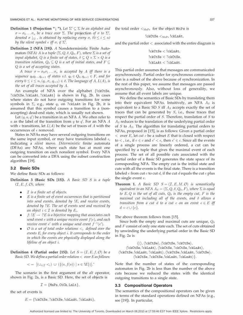
Definition 4 (Partial order [15]). Let S ¼ ðI ; E; f;OÞ be aBasic SD. We define a partial order relation< overE as follows:
< ¼ ½ð[i2I <iÞ [ ðfðs; fðsÞÞ j s 2 !EgÞ�:�
The scenario in the first argument of the alt operator,shown in Fig. 2a, is a Basic SD. Here, the set of objects is
I ¼ fMnPs; CtCk; LnLtg;
the set of events is
E ¼ f!ckCtSe; ?ckCtSe; !ckLnAt; ?ckLnAtg;
the total order <MnPs for the object MnPs is
!ckCtSe <MnPs !ckLnAt;
and the partial order< associated with the entire diagram is
!ckCtSe < !ckLnAt;
!ckCtSe < ?ckCtSe;
!ckLnAt < ?ckLnAt:
This partial order assumes that messages are communicatedasynchronously. Partial order for synchronous communica-tion is a subset of the above because of synchronization. Inthe rest of this paper, we assume that messages are passedasynchronously. Also, without loss of generality, weassume that all event labels are unique.
We define the semantics of Basic SDs by translating theminto their equivalent NFAs. Intuitively, an NFA AS isequivalent to a Basic SD S iff AS accepts exactly the set oftraces that can be generated by S, i.e., those traces thatrespect the partial order of S. Therefore, translation of S toAS reduces to the translation of the underlying partial orderof S to AS . The algorithm for translating partial orders toNFAs, proposed in [15], is as follows: Given a partial order< over E, let cut c be a subset E that is closed with respectto < , i.e., if e 2 c and e0 < e, then e0 2 c. Since all the eventsof a single process are linearly ordered, a cut can bespecified by a tuple that gives the maximal event of eachprocess. The set of all possible cuts associated with thepartial order of a Basic SD generates the state space of itscorresponding NFA. The empty cut is the initial state andcuts with all the events is the final state. There is a transitionlabeled e from cut c to cut d, if the cut d equals the cut c plusthe single event e.
Theorem 1. A Basic SD S ¼ ðI ; E;M;OÞ is semanticallyequivalent to an NFA AS ¼ ð�; Q; �;Q0; F Þ, where � is equal
to E;Q is the set of all cuts, Q0 is the empty cut, F is themaximal cut including all of the events, and � allows a
transition from a cut d to a cut c on an event e 2 E iff
d ¼ c [ feg.
The above theorem follows from [15].Since both the empty and maximal cuts are unique, Q0
and F consist of only one state each. The set of cuts obtainedby unwinding the underlying partial order in the Basic SDin Fig. 2a is
fhi; h!ckCtSei; h!ckCtSe; ?ckCtSei;h!ckCtSe; !ckLnAti; h!ckCtSe; ?ckCtSe; !ckLnAti;
h!ckCtSe; !ckLnAt; ?ckLnAti; h!ckCtSe; !ckLnAt; ?ckCtSei;h!ckCtSe; ?ckCtSe; !ckLnAt; ?ckLnAtig:
Note that the number of states of the correspondingautomaton in Fig. 2b is less than the number of the abovecuts because we reduced the states with the identicaloutgoing transitions to a single state.
3.3 Compositional Operators
The semantics of the compositional operators can be givenin terms of the standard operations defined on NFAs (e.g.,see [19]). In particular,
SIMMONDS ET AL.: RUNTIME MONITORING OF WEB SERVICE CONVERSATIONS 227
Authorized licensed use limited to: The University of Toronto. Downloaded on March 08,2010 at 17:59:46 EST from IEEE Xplore. Restrictions apply.

. par corresponds to the parallel composition operatoror the intersection operator over NFA;
. alt corresponds to the union operator;
. loop corresponds to the Kleene star operator.
The theorem below, which follows from Theorem 1 and[19], shows that the set of NFAs associated with SDs isclosed under the compositional operators.
Theorem 2. Let S; S1, and S2 be SDs, and let S ¼ S1opS2, whereop is a compositional operator. Then, AS ¼ AS1
opAS2.
For example, the automaton in Fig. 2c corresponds to thesequence diagram in Fig. 2a. As shown in the figure, theautomaton is obtained by computing the union of the twoBasic SDs corresponding to the two alternative scenarios ofthe SD in Fig. 2a. We have also added a self-loop to theinitial state of the automaton in Fig. 2c labeled with theunderlying alphabet of the SD in Fig. 2a. The self-loopallows the automaton to guess when the scenario specifiedby the SD begins.
3.4 Alphabet Changing Operators
Operators consider and ignore are used to change the set ofcommunicating alphabet of an SD. Both of them receive anSD S and a set of events E as input, but consider adds theelements in E to the set of events of S, whereas ignoreremoves the elements in E from the set of events of S.Formally, let S and S0 be SDs, E be a set of events, andAS ¼ ð�; Q; �; fq0g; F Þ be the automaton associated with S.For S0 ¼ considerES, AS0 ¼ ð� [E;Q; �; fq0g; F Þ, and forS0 ¼ ignoreES, AS0 ¼ ð� n E;Q; �0; fq0g; F Þ, where
�0 ¼�� \ ðQ� ð� n EÞ �QÞ
�[
fðq; �; q0Þ j 9� 2 E � ðq; �; q0Þ 2 �g:
It is easy to see that the set of NFAs associated with SDs isclosed under the operators consider and ignore as well.
Recall that any missing transition at a state leads to anerror state. Increasing the input alphabet � of AS withoutchanging the transition relation � means that more execu-tion traces end up in the error state, while shrinking theinput alphabet without changing the transition relationmeans that more execution traces are accepted. Forexample, the consider operator in Fig. 2a extends theunderlying alphabet � of the automaton in Fig. 2c fromf!ckCtSe; ?ckCtSe; !ckLnAt; ?ckLnAtg to f!ckCtSe; ?ckCtSe;!ckLnAt; ?ckLnAt; !ckTrID; ?ckTrIDg.
3.5 Critical Operator
A critical region in a sequence diagram can be specifiedusing the critical operator. A critical region means that thescenarios of the region cannot be interleaved by other
messages, and thus, should be treated atomically. Weformalize the semantics of this operator as follows: If thefirst message of the critical region is observed, then the restof the behavior must be observed as well, without seeingany intermediate message.
LetS be an SD enclosed within a critical operator andAS bethe automaton for S. The automaton for critical S is obtainedby adding a self-loop to every initial state of AS labeled by�nfe j9q0 2 Q0 � q0 has an outgoing transition oneg. This self-loop transition at the initial state allows the automaton towait for a satisfying run to begin. The initial state alsobecomes final.
Definition 5. Let AS ¼ ð�; Q; �; fq0g; F Þ be an NFA associatedwith an SD S and Scrit be an SD obtained by enclosing S witha critical operator. The automaton corresponding to Scrit isAcritS ¼ ð�; Q; �0; fq0g; F [ fq0gÞ, where
�0 ¼ � [ fðq0; e; q0Þ j e 2 � ^ 6 9q 2 Q � q 6¼ q0
^ ðq0; e; qÞ 2 �g:
For a sequence enclosed by a critical operator, once thefirst symbol of the sequence has been seen, the entiresequence should be seen as well. For this reason, the self-loop at the initial state of an automaton corresponding to acritical region is labeled by � minus the initial symbols of theexpected sequences. For example, Fig. 4a shows a sequencediagram with a critical operator, and Fig. 4c—its corre-sponding automaton. Similar to the automaton in Fig. 2c, wehave added a self-loop to the initial state of the automaton inFig. 4c to allow this automaton to guess when the scenario ofinterest begins.
3.6 Assertion and Negation Operators
The negate operator provides a mechanism for specifyingundesirable (negative) scenarios and the assert operatorallows us to specify desirable (positive) scenarios. The formeroperator can be used to express safety properties, e.g., P1 inTable 1, and the latter—finitary liveness properties, e.g., P2.
Various formal treatments of the semantics of the assertand negate operators are given in the literature, e.g., [16],[17], [20]. These operators have a rich expressive power, andyet, their arbitrary combinations are not well understood. Inparticular, it is unclear whether negating an assertedscenario should mean that this scenario is not required tooccur or that its negation has to occur. In this section, wedefine the semantics of assert and negate operators in termsof NFAs. Our formalization allows us to arbitrarily combinethese operators as long as we never attempt to apply anegate operator to a sequence diagram containing anasserted fragment.
228 IEEE TRANSACTIONS ON SERVICES COMPUTING, VOL. 2, NO. 3, JULY-SEPTEMBER 2009
Fig. 4. (a) A basic SD enclosed by a critical operator and its corresponding NFAs: (b) before applying critical; (c) after applying critical.
Authorized licensed use limited to: The University of Toronto. Downloaded on March 08,2010 at 17:59:46 EST from IEEE Xplore. Restrictions apply.

3.6.1 The Negate Operator
As mentioned above, negate allows us to express safetyproperties. By applying negate to an SD S, we indicatethat the scenario represented by S is forbidden, andtherefore, a safe system should never produce it [17]. Forexample, consider Fig. 5a, which shows an SD corre-sponding to the safety property P1 in Table 1. MnPs sendsa check credit score request, i.e., ckCtSe, to CtCk. Inresponse, CtCk sends the actual credit score (ctSe) toMnPs. A creditScoreNotValid (ctSeNV) message issent if the value is not in the correct range. This propertyis expressed in SD by applying a negate operator to thesequence !ckCtSe:?ckCtSe:!ctSe:?ctSe:!ctSeNV:?ctSeNV.
The negate operator over SDs is equivalent to thecomplementation operator of NFA. Given an SD S and itscorresponding automaton AS , we first add a self-looptransition labeled �, i.e., the underlying alphabet of S, to theinitial state of AS in order to enable AS to guess when asatisfying run begins. Note that after adding this self-loop,AS becomes nondeterministic. To obtain the automaton forthe negated SD, we need to first determinize AS and thencomplement the result.
For example, an automaton corresponding to the SD inFig. 5a, after adding the self-loop and before complementa-tion, is shown in Fig. 5b. Fig. 5c shows the final,complemented, automaton.
Note that since the sequence S is nonempty, the initialstate of the complement ofAS is always accepting, and hence,the empty string is always in the language of the complementof AS . This is expected because the negate operator holds1) when the negative scenario S does not completely occurand 2) when no messages at all are exchanged.
3.6.2 The Assert Operator
The meaning of the assert operator is given by the UMLstandard as follows [13]: “the sequences of the operand are theonly valid continuations. All other continuations result in invalid
behavior.” This interpretation has been formalized indifferent ways [16], [17]. The one that we have adopted isthat of [16], which is described as follows: Given an assertedbehavior � ¼ �0 . . .�n and a system behavior �0, everyoccurrence of �0 in �0 should be followed by the rest of �.Thus, an SD with an assert is interpreted universally: “forevery run, once it satisfies the start of the sequence, it mustcomplete the sequence before termination.” Note that thedifference between assert and critical is that the formerchecks all possible suffixes of the input run to probe thesequence, whereas the latter only checks the first occurrenceof its sequence.
In [16], alternating automata with universal initial statesare used to capture this meaning of assert. Such automataaccept a trace if all of the runs emanating from their initialstates are accepting. NFA, however, accepts a trace whenthere exists an accepting run emanating from the initial state.Rather than moving outside NFA (and thus, complicatingthe monitoring framework), we chose to reinterpret theacceptance for the assert operator instead: An NFA for anasserted trace � checks all suffixes of the system traces, andif one is not accepted, a failure is reported. This “universal”treatment is given to the entire sequence diagram, not justthe part containing assert. This works correctly as long assuch NFAs are not complemented or composed (inparallel)—the negation and parallel composition operatorsover automata with universally interpreted acceptance aredifferent from those operators of NFA. While negation andparallel composition operators for NFA are computed viasubset construction and cross-product, respectively, theseoperators for the alternating automata simply convertuniversal states into existential or add an additionaluniversal state, respectively [21]. Thus, we restrict theapplication of negate and par to SDs that do not contain anassert, as described in Section 2.
Since alternating automata can be converted into NFAwith a possibly exponential blowup in size, we could have
SIMMONDS ET AL.: RUNTIME MONITORING OF WEB SERVICE CONVERSATIONS 229
Fig. 5. (a) An SD describing P1 in Table 1 and its corresponding NFAs: (b) before applying negate; (c) automaton after determinization and
complementation; (d) the resulting monitor.
Authorized licensed use limited to: The University of Toronto. Downloaded on March 08,2010 at 17:59:46 EST from IEEE Xplore. Restrictions apply.

translated the assert operator directly into NFA. However,we chose not to do it to preserve the succinctness andrelatively small size of our monitoring automata.
Given the above discussion, the translation of assertoperator is straightforward: After deriving the NFA AS forSD S and adding a self-loop labeled � at its initial state, theautomaton for assert S is obtained by interpreting the initialstate as universal (we follow the notation of [16], denotingthis state with a “^”) and making it accepting. Forexample, the SD in Fig. 6a describes the liveness propertyP2 in Table 1—the desirable scenario is enclosed in thescope of an assert operator. Fig. 6b shows the automatoncorresponding to this SD.
3.7 Interaction Use Operator
The ref operator is used for referring to an SD fragmentfrom within another SD. Our treatment of ref is to inline theSD being referenced, as illustrated in Fig. 7.
3.8 Message Complementation
The message complement operator has been adoptedfrom [18]. If � is the set of messages exchanged in an SD,andm 2 �, then,:m is � n fmg. For a set fm;ng of messages,:fm;ng ¼ � n fm;ng. For example, let � ¼ fp; q; s; tg. Then,:p ¼ fq; s; tg and :fp; qg ¼ fs; tg.
This operator, although not being part of UML 2.0, can beexpressed in terms of UML operators as follows: Let S � �be a set of messages. We replace :S by an SD fragment inwhich the operator alt is applied to individual messages in� n S. For example, consider the SD in Fig. 8a with amessage :fp; qg, and let � ¼ fs; t; p; qg. This SD isequivalent to the one in Fig. 8b, where :fp; qg is replacedby an alt fragment in which s and t are two alternativemessages. The NFA for the sequence diagram without
message complement operators can be generated in a
straightforward way following the translation for the alt
operator (see Fig. 8c).
3.9 Generating Monitors from NFA
To be able to use an automaton AS obtained from an SD S
for runtime monitoring, we need to extend the language of
AS to handle system behaviors over alphabets larger than S.
We do so by adding stuttering self-loops to the automaton’s
states. Semantically, this means that AS does not change its
state when the input symbol is outside the alphabet of S.
Definition 6 (Stuttering). Let �sys be the set of system events
and A ¼ ð�; Q; �;Q0; F Þ be an NFA s.t. � � �sys. The
automaton A0 ¼ ð�sys; Q; �0; Q0; F Þ is the stutter-closed
form of A w.r.t. �sys if �0 ¼ � [ fðq;�sysn�; qÞ j 8q 2 Qg.
The transformation of Definition 6 is language preserving.
Theorem 3. Let A ¼ ð�; Q; �;Q0; F Þ be an NFA and �sys s.t.
� � �sys be given. Let A0 be the stutter-closed form of A
w.r.t. �sys (see Definition 6). Then, for every trace � 2 �sys,
� 2 LðA0Þ iff � #�2 LðAÞ (see Definition 1).
230 IEEE TRANSACTIONS ON SERVICES COMPUTING, VOL. 2, NO. 3, JULY-SEPTEMBER 2009
Fig. 6. (a) An SD describing P2 in Table 1 and its corresponding NFAs: (b) after applying assert; (c) the resulting monitor.
Fig. 7. (a) An SD with references SD C; (b) SD C; (c) SD ex after copying the content of SD C; and (d) its corresponding NFA.
Fig. 8. (a) An SD with message complementation; (b) the same SD aftereliminating the complement operator if its underlying alphabet � isfp; q; s; tg; and (c) its corresponding NFA.
Authorized licensed use limited to: The University of Toronto. Downloaded on March 08,2010 at 17:59:46 EST from IEEE Xplore. Restrictions apply.

Proof. The proof follows from the fact that the constructionof Definition 6 does not change the state space of A:
� 2 LðA0Þ
, ðBy definition of language acceptance in A0Þ
9q0; . . . ; qnþ1 2 Q � q0 2 Q0 ^ qnþ1 2 F^
8�i 2 � � �0ðqi; �i; qiþ1Þ
, ðBy definition of �0Þ
9q0; qnþ1 2 Q � q0 2 Q0 ^ qnþ1 2 F^
8�i 2 � #� ��ðqi; �i; qiþ1Þ
, ðBy definition of language acceptance in AÞ
� #�2 LðAÞ:ut
For example, the monitor corresponding to the SD inFig. 5a is shown in Fig. 5d. The language accepted by thismonitor is
��sys n���sys � !ckCtSe � ð��sys n �Þ� � ?ckCtSe�ð��sys n �Þ� � !ctSe � ð��sys n �Þ� � ?ctSe�ð��sys n �Þ� � !ctSeNV � ð��sys n �Þ� � ?ctSeNV � ��sys
�:
That is, the monitor rejects a trace that begins with a checkcredit score request (ckCtSe), which gets received (perhapswith some events not in the vocabulary of this SD in themiddle), followed by receiving the credit score (ctSe) andsending a message indicating that it is invalid (ctSeNV),followed by arbitrary events in the system. Thus, thebehaviors during which the check credit score requests aremade and results in an invalid credit score are rejected;these correspond to violations of property P1.
The monitor for the SD in Fig. 6a is shown in Fig. 6c. Itslanguage is
�ð�sys n !lnAtOkÞ� � ð!lnAtOk � ð�sys n �Þ�
� ?lnAtOk � ð�sys n �Þ�
� !ckCtSe � ð�sys n �Þ�
� ?ckCtSe���:
This monitor accepts traces that either do not exhibit!lnAtOk at all, or, if !lnAtOk has been seen, exhibit the entiresequence ?lnAtOk � !ckCtSe � ?ckCtSe. Traces not acceptedby this monitor violate property P2 of the LA system.
Note that we do not add stuttering self-loops to thecritical regions because behavior specified in critical regionscannot be interleaved by other messages.
3.10 Complexity of the Translation
The size of an automaton AS corresponding to a basic SD S,i.e., the number of states inAS , isOðnkÞ, wheren is the numberof events and k is the number of objects [15]. Applying the SDoperators does not cause a significant increase in the size ofthe resulting automata except for the cases where we need todeterminize these automata, which can exponentially in-crease their state spaces. However, in our experience, thegenerated automata have been very small (see Section 6).Obviously, it remains to see whether the approach scales tolarger Web service systems and more complex properties.
3.11 Discussion
3.11.1 On Using Our Language in MDA Tools
In this paper, we formalized the syntax of the SD languageusing a context-free grammar (see Fig. 3). As discussed inSection 5.1, we used the Rational Software Architect (RSA)[22] plug-in for WebSphere to generate an editor for SDdiagrams. To do so, we have identified a fragment of theUML metamodel that captures the SD operators describedin Fig. 3 and specified logical properties constraining thenesting and ordering of these operators. We have imple-mented a separate Java module to check these constraintsover the generated SD diagrams in our tool. In the future,we plan to encode these constraints as part of themetamodel by expressing them in the OCL [14]. This wouldmake our editor reusable in other UML environments.
3.11.2 On the Expressive Power of Our Language
In this section, we provided a transformation from ourlanguage SD to NFA, showing that SD can capture safetyand finitary liveness properties. Our transformation furthershows that SD is not more expressive than regularexpressions, i.e., the language that NFA recognizes.
The main restriction in SD is that we do not allow thenesting of asserts within the scope of negates. For example,sequence diagrams such as the one shown in Fig. 20a are notincluded in SD (we discuss these diagrams in more detail inSection 6.2). However, this restriction is mainly syntacticbecause we can always push the negate operator down to theatomic level and reformulate the sequence diagram into asemantically equivalent one in which negate is not appliedwithin the scope of assert. For example, Fig. 20b shows asequence diagram, which is semantically equivalent to theone in Fig. 20a and is within the SD language.
Note that after removing the negate operator, the resultingsequence diagram may have brand new scenarios: to do theremoval, we need to elicit the set of all possible scenarioscomplementary to the scenario enclosed by the negate. Forexample, the scenario negate(reserveHotel; hotelReserved)in Fig. 20a is replaced by two new scenarios, reserveHotel;timeout and reserveHotel; hotelNotReserved, in Fig. 20b.The process of enumeration and analysis of all possiblealternative scenarios obviously require domain knowledge,and thus, cannot be automated in general. However, theonline nature of our monitoring framework allows us toregister for and collect the alternative scenarios with ease.
4 SD TEMPLATES FOR TEMPORAL LOGIC
PROPERTY PATTERNS
In this section, we study the expressive power of our SDlanguage by using it to express temporal logic propertypatterns [1]. Property patterns have been shown to capturea wide variety of commonly used properties, and being ableto express property patterns is a good indication of anexpressive power of a new language.
We first provide an overview of property patterns inthe following section and then introduce several SDtemplates and show how they can encode the propertypatterns in Section 4.2.
SIMMONDS ET AL.: RUNTIME MONITORING OF WEB SERVICE CONVERSATIONS 231
Authorized licensed use limited to: The University of Toronto. Downloaded on March 08,2010 at 17:59:46 EST from IEEE Xplore. Restrictions apply.

4.1 Temporal Logic Property Patterns
The Specification Pattern System (SPS), proposed by Dwyeret al. [23], is a pattern-based approach to the presentation,codification, and reuse of property specifications. Thesystem allows patterns like “event P is absent betweenevents Q and S” or “S precedes P between Q and R” to beeasily expressed in and translated between linear-timetemporal logic (LTL), computational tree logic (CTL) [24]and other state-based and event-based formalisms. SPS hasbeen advocated as a standard tool for measuring thepractical usefulness and expressive power of specificationlanguages, e.g., [18] and [25].
The property patterns are organized into a hierarchybased on the kinds of system behaviors they describe (seeFig. 9a): Occurrence patterns talk about the occurrence of agiven event/state during system execution and Orderpatterns specify relative order in which multiple events/states occur during system execution. The patterns aredescribed in Table 2.
Each pattern is associated with scopes—the regions ofinterest over which the pattern must hold. There are fivebasic kinds of scopes: Global, Before, After, Between, andAfter-Until. Definitions of these scopes are given in Table 3and pictorially described in Fig. 9b.
For example, consider a property of a queue that saysthat there should be a dequeue event between everyenqueue and empty. This is the Existence pattern, with the
Between scope. Looking up the LTL formalization of thispattern/scope combination from the catalogue and sub-stituting our event names, we obtain the formula
utððenqueue ^ :emptyÞ) ð:empty W ðdequeue ^ :emptyÞÞÞ:
4.2 Mapping Property Patterns to SDs
In this section, we provide several SD templates for the SPSpatterns (see Fig. 11) and show how these templates areused to express patterns in the SPS hierarchy. Selectedmappings are described below; the remainder can be foundin the Appendix. Note that the actual direction of thearrows is determined when a template is instantiated.
Absence: message p cannot occur in a given scope. Thiscan be expressed as shown in Fig. 11a.
Existence: a message p must occur in a given scope. Thiscan be expressed as shown in Fig. 11b.
Until: This pattern is not part of the SPS; however, it isused to specify the Precedence patterns. A sequence p� ofmessages occurs until the first occurrence of message q, in agiven scope (see Fig. 11h). This pattern, formalized using asingle “until” temporal operator [24], can be refuted in oneof the two ways: either p never occurs, or after seeing afinite number of p messages (expressed using loop 1, n),neither a p nor a q message occurs (expressed as :fp; qg).
232 IEEE TRANSACTIONS ON SERVICES COMPUTING, VOL. 2, NO. 3, JULY-SEPTEMBER 2009
TABLE 2SPS Patterns
TABLE 3SPS Scopes
Fig. 9. Specification property system: (a) a pattern hierarchy and (b) pattern scopes.
Authorized licensed use limited to: The University of Toronto. Downloaded on March 08,2010 at 17:59:46 EST from IEEE Xplore. Restrictions apply.

Precedence: a message s (cause) precedes a message p
(effect), as shown in Fig. 11i. This pattern allows the causepart to occur without the effect. We describe this patternin SD by expressing the two possible cases that thispattern specifies: 1) p never occurs or 2) p never occursbefore s. The first case corresponds to checking absence ofp; the second—to checking :p U s (the “until” template),since we want to be sure that no p messages are sentbefore the first s message.
In the SDs in Fig. 11, symbols p, q, s, and t can denotecomplex SDs rather than just the individual messages. Inthis case, we treat these symbols as placeholders, use a refoperator for the SDs that should be inserted in their place,and replace message complementation by negation.
4.3 Mapping Property Scopes
We now show how to express property patterns involvingscopes that are used to define the traces over which a
property will be monitored. Scopes can be simple messages
or more complex scenarios in our specification language.
The ref operator is used to introduce scope delimiters in the
corresponding locations. For example, to apply the Before
R scope to a property, the scope delimiter R is inserted
after the property we wish to verify (see Fig. 10a). In the
case of the After Q scope, the delimiter is inserted before
the property (see Fig. 10b). Finally, both the Between (see
Fig. 10c) and After-until (see Fig. 10d) scopes add before/
after delimiters. In the After-until scope, the property is
valid even if the “until” part does not occur. Therefore, the
second delimiter in this scope is optional. Thus, there is an
implicit opt operator in each scope delimiter.
4.4 Specifying Properties of the Loan Application
We now show how property patterns can be used to express
properties of the LA system given in Table 1. Properties P1
SIMMONDS ET AL.: RUNTIME MONITORING OF WEB SERVICE CONVERSATIONS 233
Fig. 10. Scope mapping for sequence diagrams: (a) Before R; (b) After Q; (c) Between Q and R; and (d) After Q until R.
Fig. 11. Property pattern mappings for SDs: ðs; tÞ means message s followed by message t. (a) Absence. (b) Existence. (c) Bounded Existence.(d) Universality. (e) Response. (f) Response Chain: 2 stimulus - 1 response. (g) Response Chain: 1 stimulus - 2 response. (h) Until.(i) Precedence. (j) Precedence Chain: 2 cause - 1 effect.
Authorized licensed use limited to: The University of Toronto. Downloaded on March 08,2010 at 17:59:46 EST from IEEE Xplore. Restrictions apply.
and P2 are described in Figs. 5 and 6, respectively. The rest
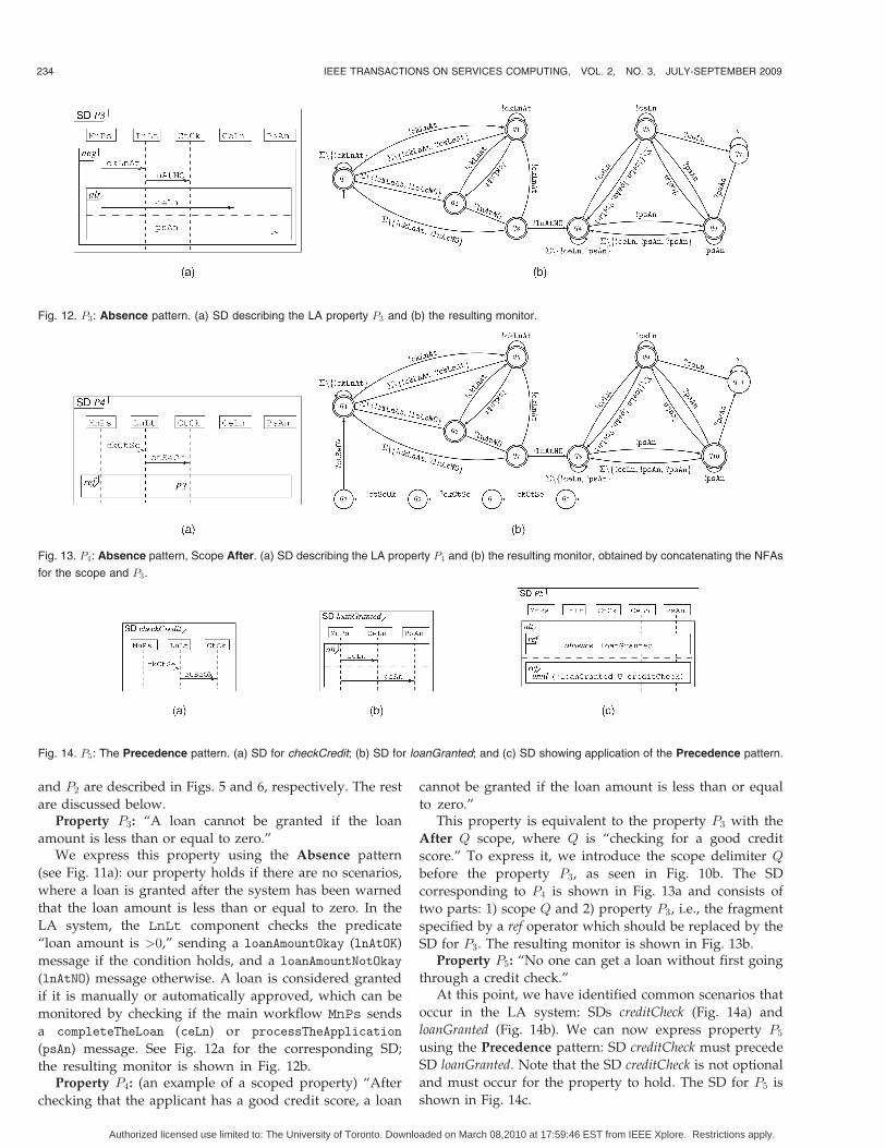
are discussed below.Property P3: “A loan cannot be granted if the loan
amount is less than or equal to zero.”We express this property using the Absence pattern
(see Fig. 11a): our property holds if there are no scenarios,
where a loan is granted after the system has been warned
that the loan amount is less than or equal to zero. In the
LA system, the LnLt component checks the predicate
“loan amount is >0,” sending a loanAmountOkay (lnAtOK)
message if the condition holds, and a loanAmountNotOkay
(lnAtNO) message otherwise. A loan is considered granted
if it is manually or automatically approved, which can be
monitored by checking if the main workflow MnPs sends
a completeTheLoan (ceLn) or processTheApplication
(psAn) message. See Fig. 12a for the corresponding SD;
the resulting monitor is shown in Fig. 12b.Property P4: (an example of a scoped property) “After
checking that the applicant has a good credit score, a loan
cannot be granted if the loan amount is less than or equal
to zero.”This property is equivalent to the property P3 with the
After Q scope, where Q is “checking for a good credit
score.” To express it, we introduce the scope delimiter Q
before the property P3, as seen in Fig. 10b. The SD
corresponding to P4 is shown in Fig. 13a and consists of
two parts: 1) scope Q and 2) property P3, i.e., the fragment
specified by a ref operator which should be replaced by the
SD for P3. The resulting monitor is shown in Fig. 13b.Property P5: “No one can get a loan without first going
through a credit check.”At this point, we have identified common scenarios that
occur in the LA system: SDs creditCheck (Fig. 14a) and
loanGranted (Fig. 14b). We can now express property P5
using the Precedence pattern: SD creditCheck must precede
SD loanGranted. Note that the SD creditCheck is not optional
and must occur for the property to hold. The SD for P5 is
shown in Fig. 14c.
234 IEEE TRANSACTIONS ON SERVICES COMPUTING, VOL. 2, NO. 3, JULY-SEPTEMBER 2009
Fig. 12. P3: Absence pattern. (a) SD describing the LA property P3 and (b) the resulting monitor.
Fig. 13. P4: Absence pattern, Scope After. (a) SD describing the LA property P4 and (b) the resulting monitor, obtained by concatenating the NFAs
for the scope and P3.
Fig. 14. P5: The Precedence pattern. (a) SD for checkCredit; (b) SD for loanGranted; and (c) SD showing application of the Precedence pattern.
Authorized licensed use limited to: The University of Toronto. Downloaded on March 08,2010 at 17:59:46 EST from IEEE Xplore. Restrictions apply.
5 ARCHITECTURE AND IMPLEMENTATION
We have implemented our runtime framework within theIBM WebSphere business integration products [26]. In whatfollows, we describe the architecture of our solution anddiscuss some of the more challenging parts of theimplementation.
5.1 Architecture
Our solution uses the WebSphere Process Server [27] andthe WebSphere Integration Developer [28]. The formerprovides a BPEL-compliant process engine for executingBPEL processes and a built-in Service Component Archi-tecture (SCA), which is a particular instantiation of SOA.The latter provides a development environment for build-ing Web service applications and a graphical package forcreating UML Sequence Diagrams.
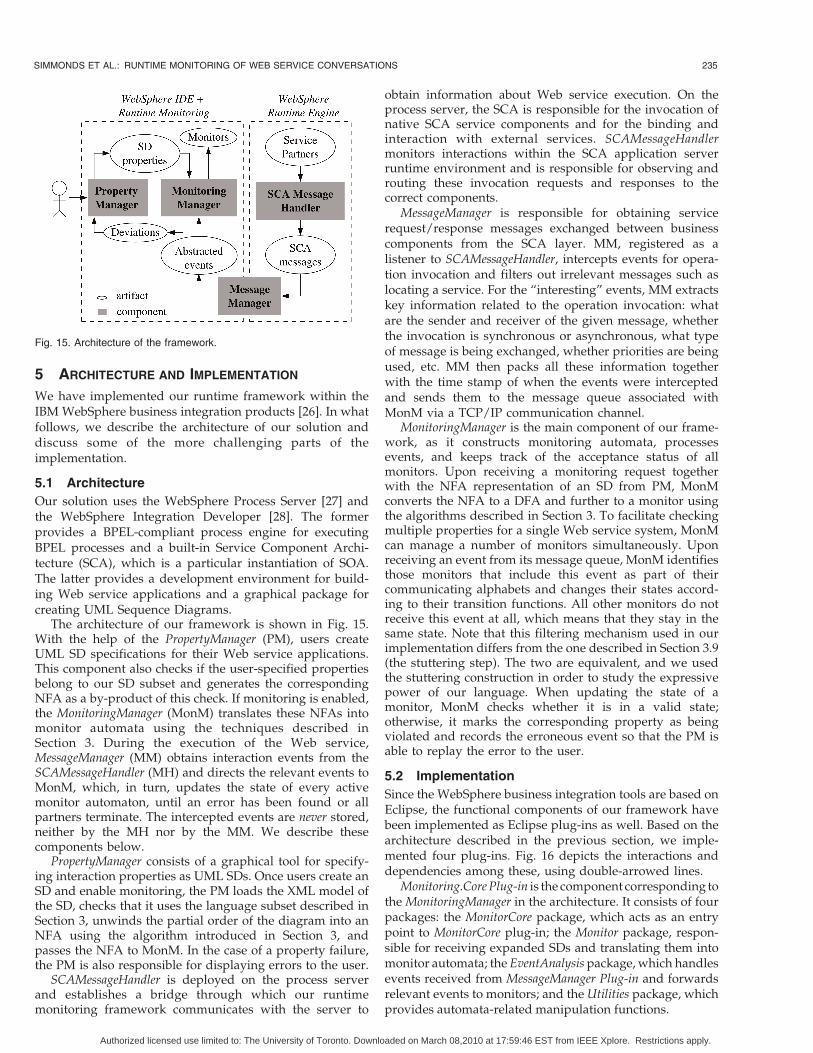
The architecture of our framework is shown in Fig. 15.With the help of the PropertyManager (PM), users createUML SD specifications for their Web service applications.This component also checks if the user-specified propertiesbelong to our SD subset and generates the correspondingNFA as a by-product of this check. If monitoring is enabled,the MonitoringManager (MonM) translates these NFAs intomonitor automata using the techniques described inSection 3. During the execution of the Web service,MessageManager (MM) obtains interaction events from theSCAMessageHandler (MH) and directs the relevant events toMonM, which, in turn, updates the state of every activemonitor automaton, until an error has been found or allpartners terminate. The intercepted events are never stored,neither by the MH nor by the MM. We describe thesecomponents below.
PropertyManager consists of a graphical tool for specify-ing interaction properties as UML SDs. Once users create anSD and enable monitoring, the PM loads the XML model ofthe SD, checks that it uses the language subset described inSection 3, unwinds the partial order of the diagram into anNFA using the algorithm introduced in Section 3, andpasses the NFA to MonM. In the case of a property failure,the PM is also responsible for displaying errors to the user.
SCAMessageHandler is deployed on the process serverand establishes a bridge through which our runtimemonitoring framework communicates with the server to
obtain information about Web service execution. On theprocess server, the SCA is responsible for the invocation ofnative SCA service components and for the binding andinteraction with external services. SCAMessageHandlermonitors interactions within the SCA application serverruntime environment and is responsible for observing androuting these invocation requests and responses to thecorrect components.
MessageManager is responsible for obtaining servicerequest/response messages exchanged between businesscomponents from the SCA layer. MM, registered as alistener to SCAMessageHandler, intercepts events for opera-tion invocation and filters out irrelevant messages such aslocating a service. For the “interesting” events, MM extractskey information related to the operation invocation: whatare the sender and receiver of the given message, whetherthe invocation is synchronous or asynchronous, what typeof message is being exchanged, whether priorities are beingused, etc. MM then packs all these information togetherwith the time stamp of when the events were interceptedand sends them to the message queue associated withMonM via a TCP/IP communication channel.
MonitoringManager is the main component of our frame-work, as it constructs monitoring automata, processesevents, and keeps track of the acceptance status of allmonitors. Upon receiving a monitoring request togetherwith the NFA representation of an SD from PM, MonMconverts the NFA to a DFA and further to a monitor usingthe algorithms described in Section 3. To facilitate checkingmultiple properties for a single Web service system, MonMcan manage a number of monitors simultaneously. Uponreceiving an event from its message queue, MonM identifiesthose monitors that include this event as part of theircommunicating alphabets and changes their states accord-ing to their transition functions. All other monitors do notreceive this event at all, which means that they stay in thesame state. Note that this filtering mechanism used in ourimplementation differs from the one described in Section 3.9(the stuttering step). The two are equivalent, and we usedthe stuttering construction in order to study the expressivepower of our language. When updating the state of amonitor, MonM checks whether it is in a valid state;otherwise, it marks the corresponding property as beingviolated and records the erroneous event so that the PM isable to replay the error to the user.
5.2 Implementation
Since the WebSphere business integration tools are based onEclipse, the functional components of our framework havebeen implemented as Eclipse plug-ins as well. Based on thearchitecture described in the previous section, we imple-mented four plug-ins. Fig. 16 depicts the interactions anddependencies among these, using double-arrowed lines.
Monitoring.Core Plug-in is the component corresponding tothe MonitoringManager in the architecture. It consists of fourpackages: the MonitorCore package, which acts as an entrypoint to MonitorCore plug-in; the Monitor package, respon-sible for receiving expanded SDs and translating them intomonitor automata; the EventAnalysis package, which handlesevents received from MessageManager Plug-in and forwardsrelevant events to monitors; and the Utilities package, whichprovides automata-related manipulation functions.
SIMMONDS ET AL.: RUNTIME MONITORING OF WEB SERVICE CONVERSATIONS 235
Fig. 15. Architecture of the framework.
Authorized licensed use limited to: The University of Toronto. Downloaded on March 08,2010 at 17:59:46 EST from IEEE Xplore. Restrictions apply.
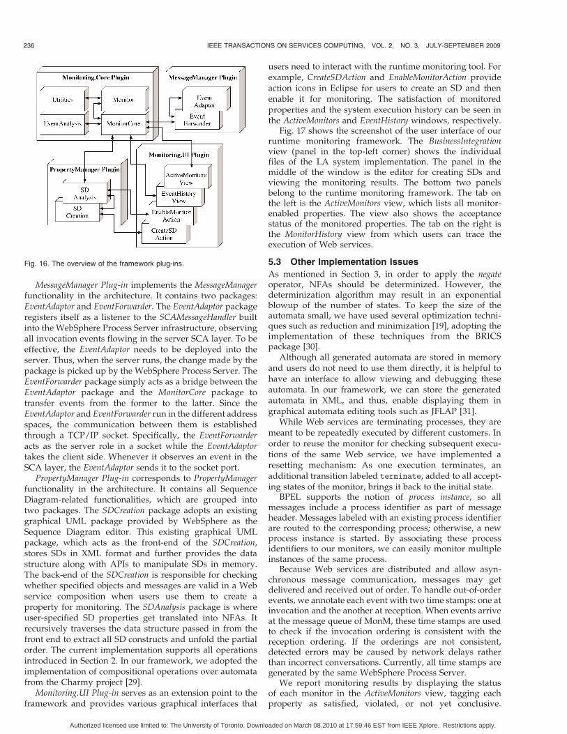
MessageManager Plug-in implements the MessageManagerfunctionality in the architecture. It contains two packages:EventAdaptor and EventForwarder. The EventAdaptor packageregisters itself as a listener to the SCAMessageHandler builtinto the WebSphere Process Server infrastructure, observingall invocation events flowing in the server SCA layer. To beeffective, the EventAdaptor needs to be deployed into theserver. Thus, when the server runs, the change made by thepackage is picked up by the WebSphere Process Server. TheEventForwarder package simply acts as a bridge between theEventAdaptor package and the MonitorCore package totransfer events from the former to the latter. Since theEventAdaptor and EventForwarder run in the different addressspaces, the communication between them is establishedthrough a TCP/IP socket. Specifically, the EventForwarderacts as the server role in a socket while the EventAdaptortakes the client side. Whenever it observes an event in theSCA layer, the EventAdaptor sends it to the socket port.
PropertyManager Plug-in corresponds to PropertyManagerfunctionality in the architecture. It contains all SequenceDiagram-related functionalities, which are grouped intotwo packages. The SDCreation package adopts an existinggraphical UML package provided by WebSphere as theSequence Diagram editor. This existing graphical UMLpackage, which acts as the front-end of the SDCreation,stores SDs in XML format and further provides the datastructure along with APIs to manipulate SDs in memory.The back-end of the SDCreation is responsible for checkingwhether specified objects and messages are valid in a Webservice composition when users use them to create aproperty for monitoring. The SDAnalysis package is whereuser-specified SD properties get translated into NFAs. Itrecursively traverses the data structure passed in from thefront end to extract all SD constructs and unfold the partialorder. The current implementation supports all operationsintroduced in Section 2. In our framework, we adopted theimplementation of compositional operations over automatafrom the Charmy project [29].
Monitoring.UI Plug-in serves as an extension point to theframework and provides various graphical interfaces that
users need to interact with the runtime monitoring tool. Forexample, CreateSDAction and EnableMonitorAction provideaction icons in Eclipse for users to create an SD and thenenable it for monitoring. The satisfaction of monitoredproperties and the system execution history can be seen inthe ActiveMonitors and EventHistory windows, respectively.
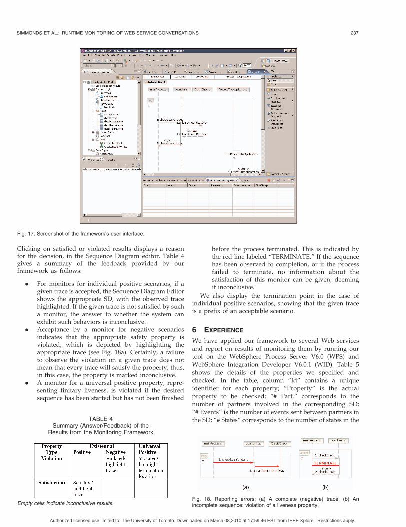
Fig. 17 shows the screenshot of the user interface of ourruntime monitoring framework. The BusinessIntegrationview (panel in the top-left corner) shows the individualfiles of the LA system implementation. The panel in themiddle of the window is the editor for creating SDs andviewing the monitoring results. The bottom two panelsbelong to the runtime monitoring framework. The tab onthe left is the ActiveMonitors view, which lists all monitor-enabled properties. The view also shows the acceptancestatus of the monitored properties. The tab on the right isthe MonitorHistory view from which users can trace theexecution of Web services.
5.3 Other Implementation Issues
As mentioned in Section 3, in order to apply the negateoperator, NFAs should be determinized. However, thedeterminization algorithm may result in an exponentialblowup of the number of states. To keep the size of theautomata small, we have used several optimization techni-ques such as reduction and minimization [19], adopting theimplementation of these techniques from the BRICSpackage [30].
Although all generated automata are stored in memoryand users do not need to use them directly, it is helpful tohave an interface to allow viewing and debugging theseautomata. In our framework, we can store the generatedautomata in XML, and thus, enable displaying them ingraphical automata editing tools such as JFLAP [31].
While Web services are terminating processes, they aremeant to be repeatedly executed by different customers. Inorder to reuse the monitor for checking subsequent execu-tions of the same Web service, we have implemented aresetting mechanism: As one execution terminates, anadditional transition labeled terminate, added to all accept-ing states of the monitor, brings it back to the initial state.
BPEL supports the notion of process instance, so allmessages include a process identifier as part of messageheader. Messages labeled with an existing process identifierare routed to the corresponding process; otherwise, a newprocess instance is started. By associating these processidentifiers to our monitors, we can easily monitor multipleinstances of the same process.
Because Web services are distributed and allow asyn-chronous message communication, messages may getdelivered and received out of order. To handle out-of-orderevents, we annotate each event with two time stamps: one atinvocation and the another at reception. When events arriveat the message queue of MonM, these time stamps are usedto check if the invocation ordering is consistent with thereception ordering. If the orderings are not consistent,detected errors may be caused by network delays ratherthan incorrect conversations. Currently, all time stamps aregenerated by the same WebSphere Process Server.
We report monitoring results by displaying the statusof each monitor in the ActiveMonitors view, tagging eachproperty as satisfied, violated, or not yet conclusive.
236 IEEE TRANSACTIONS ON SERVICES COMPUTING, VOL. 2, NO. 3, JULY-SEPTEMBER 2009
Fig. 16. The overview of the framework plug-ins.
Authorized licensed use limited to: The University of Toronto. Downloaded on March 08,2010 at 17:59:46 EST from IEEE Xplore. Restrictions apply.
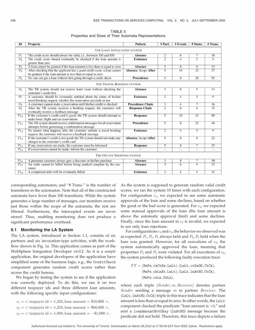
Clicking on satisfied or violated results displays a reasonfor the decision, in the Sequence Diagram editor. Table 4gives a summary of the feedback provided by ourframework as follows:
. For monitors for individual positive scenarios, if agiven trace is accepted, the Sequence Diagram Editorshows the appropriate SD, with the observed tracehighlighted. If the given trace is not satisfied by sucha monitor, the answer to whether the system canexhibit such behaviors is inconclusive.
. Acceptance by a monitor for negative scenariosindicates that the appropriate safety property isviolated, which is depicted by highlighting theappropriate trace (see Fig. 18a). Certainly, a failureto observe the violation on a given trace does notmean that every trace will satisfy the property; thus,in this case, the property is marked inconclusive.
. A monitor for a universal positive property, repre-senting finitary liveness, is violated if the desiredsequence has been started but has not been finished
before the process terminated. This is indicated bythe red line labeled “TERMINATE.” If the sequencehas been observed to completion, or if the processfailed to terminate, no information about thesatisfaction of this monitor can be given, deemingit inconclusive.
We also display the termination point in the case ofindividual positive scenarios, showing that the given traceis a prefix of an acceptable scenario.
6 EXPERIENCE
We have applied our framework to several Web services
and report on results of monitoring them by running ourtool on the WebSphere Process Server V6.0 (WPS) andWebSphere Integration Developer V6.0.1 (WID). Table 5
shows the details of the properties we specified andchecked. In the table, column “Id” contains a uniqueidentifier for each property; “Property” is the actual
property to be checked; “# Part.” corresponds to thenumber of partners involved in the corresponding SD;“# Events” is the number of events sent between partners in
the SD; “# States” corresponds to the number of states in the
SIMMONDS ET AL.: RUNTIME MONITORING OF WEB SERVICE CONVERSATIONS 237
TABLE 4Summary (Answer/Feedback) of the
Results from the Monitoring Framework
Empty cells indicate inconclusive results.Fig. 18. Reporting errors: (a) A complete (negative) trace. (b) Anincomplete sequence: violation of a liveness property.
Fig. 17. Screenshot of the framework’s user interface.
Authorized licensed use limited to: The University of Toronto. Downloaded on March 08,2010 at 17:59:46 EST from IEEE Xplore. Restrictions apply.
corresponding automaton; and “# Trans.” is the number of
transitions in the automaton. Note that all of the constructed
automata have fever than 100 transitions. While the system
generates a large number of messages, our monitors receive
just those within the scope of the automata; the rest are
filtered. Furthermore, the intercepted events are never
stored. Thus, enabling monitoring does not produce a
significant performance overhead.
6.1 Monitoring the LA System
The LA system, introduced in Section 1.1, consists of six
partners and six invocation-type activities, with the work-
flow shown in Fig. 1a. This application comes as part of the
WebSphere Integration Developer v6.0.2. As it is a sample
application, the original developers of the application have
simplified some of the business logic, e.g., the CreditCheck
component generates random credit scores rather than
access the credit bureau.We began by testing the system to see if the application
was correctly deployed. To do this, we ran it on two
different taxpayer ids and three different loan amounts,
with the following specific input configurations:
c1 ¼ < taxpayer id ¼ 1;234; loan amount ¼ $10;000 >;
c2 ¼ < taxpayer id ¼ 1;234; loan amount ¼ $60;000 >;
c3 ¼ < taxpayer id ¼ 1;888; loan amount ¼ �$1;000 >:
As the system is supposed to generate random valid credit
scores, we ran the system 10 times with each configuration.
For configuration c1, we expected to see some automatic
approvals of the loan and some declines, based on whether
the good or the bad score is generated. For c2, we expected
some manual approvals of the loan (the loan amount is
above the automatic approval limit) and some declines.
Finally, since the loan amount in c3 is invalid, we expected
to see only loan rejections.For configurations c1 and c2, the behavior we observed was
as expected: P1; P2; P5 always held and P3; P4 held when the
loan was granted. However, for all executions of c3, the
system automatically approved the loan, meaning that
properties P3 and P4 were violated. For all executions of c3,
the system produced the following faulty execution trace:
FT ¼ ðMnPs; ckCtSe; LnLtÞ; ðLnLt; ctSeOK; CtCkÞ;ðMnPs; ckLnAt; LnLtÞ; ðLnLt; lnAtNO; CtCkÞ;ðMnPs; ceLn; CeLnÞ;
where each triple ðSender;m;ReceiverÞ denotes partner
Sender sending a message m to partner Receiver. The
ðLnLt; lnAtNO; CtCkÞ triple in this trace indicates that the loan
amount is less than or equal to zero. In other words, the LnLt
component checked the predicate “loan amount is >0,” and
sent a loanAmountNotOkay (lnAtNO) message because the
predicate did not hold. Therefore, this trace depicts a failure
238 IEEE TRANSACTIONS ON SERVICES COMPUTING, VOL. 2, NO. 3, JULY-SEPTEMBER 2009
TABLE 5Properties and Sizes of Their Automata Representations
Authorized licensed use limited to: The University of Toronto. Downloaded on March 08,2010 at 17:59:46 EST from IEEE Xplore. Restrictions apply.

of P3 because it includes an invalid behavior, the acceptanceof the invalid loan, indicated by the subtrace
ðMnPs; ckLnAt; LnLtÞ;ðLnLt; lnAtNO; CtCkÞ;ðMnPs; ceLn; CeLnÞ:
As P4 is a scoped version of P3, it also fails on this trace.To identify the cause of the violations, we examined the
BPEL diagram in Fig. 1a to see that the trace FT is producedif the LA system obtains the taxpayer’s credit score, checksif the credit score is greater than 750 (ScoreEvaluation),checks if the loan amount is greater than zero (inputvalidation), and checks if the loan amount is less than$50,001 (AutoApprovalTest). The ScoreEvaluation shouldonly occasionally be true, as the CreditCheck componentgenerates random credit scores. However, we obtainedtrace FT every time the system was run with the taxpayer id1888, i.e., the system always approved a negative loan.
We traced this behavior to two problems. The first,identified after looking at the BPEL code of the LA system,was that the application did not use the results of the inputvalidation, allowing requests for negative loans to gothrough. The second problem was only identified afterexamining the source code for the CreditCheck partner.Instead of ignoring the taxpayer id and generating arandom credit score, this component always returns a goodcredit score when the taxpayer id ends with “888.”Combined, these two problems yielded the approval ofthe loan for configuration c3 every single time.
Overall, our experience showed that the system canhandle simultaneous failure of several monitors andallowed us to specify interesting properties, which led tothe discovery of two real faults in the LA system.
6.2 Monitoring Other Applications
Additionally, we modeled and checked two other applica-tions: the travel booking (TB) system and the OnlineShopping (OS) System.
6.2.1 The Travel Booking System
TB acts as a broker offering its customers the ability to bookall aspects of a trip. The workflow of TB system includes
credit validation, flight/hotel/car reservation, and commu-nication with the client. Customers can submit data abouttheir desired travel plans and receive either a confirmationnumber or a failure message depending on whether thetravel arrangements have been made successfully. Theactivity diagram in Fig. 19 shows high-level steps that areexecuted during the travel booking process.
To fulfill its business goal, the TB system needs tointeract with several partners: CreditCardChecking service,which validates the customer’s credit card data;FlightReservation service, which books a flight;HotelReservation service, which reserves a hotel room;and CarReservation service, which makes a car reserva-tion. In a typical scenario, an Internet customer begins aninteraction with the TB system by entering data for his/hertravel arrangements. The system then invokes theCreditCardChecking service, and if the credit card is valid,it tries to make hotel, flight, and car reservations. If all of thereservations are completed successfully, a confirmationnumber is generated and returned to the customer.
Table 5 lists properties we checked on this system (P6-P15). For example, P6 includes six events among threepartners and is represented by an automaton with six statesand 23 transitions. Five properties, P6, P7, P12, P13, and P14,are monitorable using patterns in the Occurrence hierarchy(see Fig. 9b). Four properties, P8, P9, P10, and P11, aremonitorable using patterns in the Order hierarchy.
Property P15 can be expressed in UML 2.0 SequenceDiagram language but not in our specification language SD.The reason for this limitation is the chosen set of events ofthe TB system: Hotel reservations are handled only by twoevents: reserveHotel (the request) and hotelReserved
(confirmation of the success). Thus, failure to reserve thehotel means that we were unable to receive the confirmationmessage. Since it is not clear how long the service shouldwait before declaring a failure, we have to express theproperty using an assert inside a negate, as shown in Fig. 20a,which is not allowed in our language (see Section 3.6.2). Theproblem can be fixed by adding two additional events to theTB system that give a reason why the hotel reservation fails:timeout (produced if a confirmation is not received by acertain time) and hotelNotReserved (produced if thereservation could not be obtained). With these, propertyP15 can be expressed as shown in Fig. 20b, which is withinthe SD language.
We checked properties P6-P14 on two versions of the TBsystem: the complete system shown in Fig. 19 and a version
SIMMONDS ET AL.: RUNTIME MONITORING OF WEB SERVICE CONVERSATIONS 239
Fig. 19. The activity diagram of the TB system.
Fig. 20. Expressing property P15: (a) using the existing alphabet of the
TB system; (b) with additional events.
Authorized licensed use limited to: The University of Toronto. Downloaded on March 08,2010 at 17:59:46 EST from IEEE Xplore. Restrictions apply.

where we removed the error handler for invalid credit cards(dashed links in Fig. 19). We did not detect any errors whenrunning the complete system against these properties.When running the modified version of the system, themonitoring framework was able to detect a violation of theproperty P7 when the user submitted a travel request withan invalid card, and reported this violation by showing thatthe event displayResult is missing. We believe that thisfeedback would have been useful for debugging of theTravel Booking System.
6.2.2 The Online Shopping System
This system implements a typical online shopping serviceand consists of four partners and 20 invocation-typeactivities. These activities are invoked via asynchronous orsynchronous message passing. For a complete descriptionof the system, see [32].
The first two properties, P16 and P17 in Table 5, areexpressed using the Absence pattern. The remainingproperty, P18, is expressed using the Existence pattern.We did not detect errors in the OS system when running itagainst these properties.
6.2.3 Summary
Overall, our experience showed that SD is a languageexpressive enough to capture a variety of properties ofexisting Web service applications, and all of the propertiesexcept one could be expressed using the pattern system.Expressing the remaining property required enriching theset of events in the corresponding system. Despite apotential exponential increase in the size of monitoringautomata, we did not encounter it in examples we havetried, and thus, monitoring always yielded negligibleoverhead. Finally, the experience of encountering an errorin an existing application, which resulted in a simultaneousfailure of several monitors, allowed us to conclude that ourframework can be used to facilitate effective debugging.
7 RELATED WORK
The main contributions of our work are the definition of aruntime monitoring language and the creation of a dynamicruntime monitoring framework based on this language.Thus, we first summarize some work studying UML 2.0Sequence Diagrams as a specification language. Afterward,we survey the research on runtime monitoring in thecontext of Web services.
7.1 Sequence Diagrams as a SpecificationLanguage
Like other partial-order scenario-based formalisms such asMSCs [11] and LSCs [12], UML Sequence Diagrams areenjoying an increasing usage as a specification language.
Lettrari and Klose [33] show how UML 1.3 SequenceDiagrams can be used to check properties of UML models.UML 1.3 SDs allow only simple event sequences, so thelanguage formalized in [33] is a small subset of ourspecification language.
Ameedeen and Bordbar [34] show how a subset ofUML 2.0 SDs can be transformed into Free Choice Petrinets, enabling the use of the corresponding analysis
techniques. This SD subset is only used to specify possiblesystem behaviors, and thus, does not include the negate andassert operators. This work also assumes that sending andreceiving an event happen simultaneously. While thisassumption works well for synchronous systems, it doesnot hold for most Web applications that rely on messagequeues for communication.
Autili et al. [18] propose a PSC language, which is anextended notation of a subset of UML 2.0 SDs. PSC enablesexpressing safety and liveness properties by assigningattributes fail and required to messages. This is equivalentto applying operators negate and assert to individual SDmessage, respectively. The semantics of PSC is given usingBuchi Automata, designed to operate on infinite executiontraces. Since we consider only finite executions of Webservices, automata over finite words are sufficient andsignificantly easier to implement.
STAIRS [35] is a trace-based requirement specificationmethodology that also uses extended UML 2.0 SDs. Tracescenarios are classified into positive (mandatory andpotential), negative, and inconclusive. Negative traces arecaptured using the negate operator. STAIRS does not useassert and instead defines a new mandatory choiceoperator, xalt, to express the requirement that bothalternatives be present in a choice. In our work, we enableexpression of mandatory and forbidden behaviors withoutextending the language.
Grosu and Smolka [17] interpret positive and negativeUML 2.0 Sequence Diagrams as safety and liveness proper-ties and give formal semantics for such diagrams usingSafety and Liveness automata, respectively. Their approachdoes not use the assert operator and defines automata overinfinite traces.
Harel and Maoz [16] define Modal Sequence Diagrams(MSD), an extension of UML 2.0 Sequence Diagrams. Thesemantics of negate and assert operators in MSD is given viathe universal/existential distinction made by the LSCs [12].In this formalism, diagrams, messages, and constraints canbe defined as either hot (universal) or cold (existential), andthe semantics of MSDs is given via alternating weak wordautomata (AFA). This formalism includes not only non-deterministic choices of NFA (the language into which wetranslated SDs) but universal choices as well [16]. Giventhat any AFA can be translated to an (exponentially larger)NFA [21], we believe that SDs and LSCs have the sameexpressive power. These languages, however, differ in theirsyntactic and usability properties. Specifically, LSCs aremore succinct because they can freely combine nondeter-ministic and universal choices. However, SDs are easier toimplement and use in a monitoring framework because ofthe existence of several efficient packages for manipulatingNFAs. Moreover, unlike LSCs, the syntax of SDs conformsto UML 2.0, and hence, many existing UML tools can beused to capture and display these diagrams.
The same authors discuss how LSC specifications can beused to monitor the execution of the program using aspects[36] (a method used by several runtime monitoring frame-works described in the literature, e.g., [37]), but the exacttranslation from alternating automata into AspectJ and theresulting complexity of the approach are unclear. Finally, an
240 IEEE TRANSACTIONS ON SERVICES COMPUTING, VOL. 2, NO. 3, JULY-SEPTEMBER 2009
Authorized licensed use limited to: The University of Toronto. Downloaded on March 08,2010 at 17:59:46 EST from IEEE Xplore. Restrictions apply.

existential, constant, subset of LSCs has been expressed interms of NFA [38]. It is a strict subset of SDs, not allowinguniversal traces.
While we concentrated on specifying behavioral proper-ties of interactions between partners, Bultan [39] identifiedCollaboration Diagrams (CDs) and Conversation Protocols(CPs) as more appropriate formalisms for specifying suchproperties as realizability and synchronizability, which hethen checks using model-checking. These formalisms aresimpler than UML 2.0 Sequence Diagrams and are appro-priate for expressing such special-purpose properties.
7.2 Runtime Monitoring of Web Services
In this section, we compare our approach to existingruntime monitoring techniques. Online (offline) techniquesanalyze system events during (after) execution and theproperties to check are determined a priori (a posteriori).Examples of the online techniques are [40], [41], [42], [43],[44], [45], and [46], [47], [48] are the offline techniques.
These techniques differ in the types of properties theycan handle. Global properties allow the analysis of orche-strated obligations. These obligations are expressed fromthe point of view of the orchestrating service, but alsoinclude events from the other services involved in theconversation being monitored. Local properties are restrictedto monitoring the events of a single service. Furthermore,some techniques concentrate on state properties, whereasothers allow the user to express sequences of events. Likeours’, the approach introduced by Pistore and Traverso [43]can be used to check global properties. In [43], propertiesare specified in LTL, which is more expressive than ourspecification language. However, specifying propertiescorrectly in LTL can be challenging, especially when tryingto specify sequences of events [1], whereas these are quiteintuitive in our framework.
The frameworks described in [40], [41], [42], [44], [45] arerestricted to local properties. Li et al. [45] specify propertiesusing Interaction Constraints (ICs) [49]—a language basedon Dwyer et al.’s Specification Pattern System [1]. Unlikeour specification language, IC does not allow patternnesting. Thus, new events must be introduced in order toreason about sequences of events. The rest of the localproperty frameworks check state formulas, specified usingsimple predicate logic. Specifically, Baresi et al. [41], [42]and Lohmann et al. [44] check service pre- and postcondi-tions associated to external service invocations, whileLazovik et al. [40] check local assertions.
Offline techniques can handle both global and localproperties. In the work of Mahbub and Spanoudakis [46],[47], properties are expressed using event calculus [50]. vander Aalst and Pesic [48] introduce DerSecFlow, a graphicallanguage that can be used to express properties similar toour patterns, but without pattern nesting.
Various techniques are used for checking properties. Theauthors of [40] and [43] rely on planning techniques tocreate service compositions. Pistore and Traverso [43]analyze the application once the composition has beenobtained, by instrumenting the system to include Java codethat checks LTL monitors during runtime. Lazovik et al. [40]iteratively replace the violated service with another one,
with weaker assertions, continuing the process until thereare no more violations, or the composition is not possible.
In the case of service pre- and postconditions, theauthors of [41], [42] modify the original BPEL diagram,introducing new BPEL activities that check the contractduring external service calls. The authors of [44] propose asimilar, but more intrusive framework, as JML contracts areintegrated at the source code level. The authors of [46], [47]use temporal deductive databases to store and reason aboutevents generated during runtime, while the authors of [48]analyze low-level event logs using an LTL checker.
Techniques used in the work of Li et al. [45] are theclosest to ours. Like us, they take an automata-basedapproach for monitoring communications between partnersand enable graphical display of violations.
As discussed before, the advantage of online techniquesis that it is possible for the system to react once a problemhas been detected. In [41], [42], BPEL exception handlerscan be attached to the properties being checked. If such anexception handler is not provided, execution terminateswhen a violation occurs. As [43], [44] are Java-based, theycan use Java’s exception handling mechanism for recoveryactions; however, this approach is highly intrusive. Li et al.[49] do not discuss recovery. Offline techniques like [46],[47], [48] instead suggest corrective actions, which can betested during future executions.
8 CONCLUSION AND FUTURE WORK
In this paper, we described our framework for runtimemonitoring of Web service conversations developed as partof an industrial-strength system. The framework is anaggregation of existing runtime verification techniques. It isnonintrusive, running in parallel with the monitored systemand intercepting interaction events during runtime. Thus, itdoes not require any code instrumentation, does notsignificantly affect the performance of the monitoredsystem, and enables reasoning about partners expressedin different languages. Furthermore, the use of a subset ofUML 2.0 SDs as a specification language ensures that theframework is usable by practitioners to specify safety andliveness properties. Liveness becomes finitary, where user-specified time limits or the process termination acts as thestopping event.
We have successfully mapped all the SpecificationProperty System patterns into our SD subset. The avail-ability of customizable patterns should improve theusability of our specification language. More complexconversations can be checked, as it is easy to buildproperties through SD composition. Using SD references,our properties are also easier to read, since details can behidden. We have also created a library of such sequencediagram patterns and shown how patterns can be used tospecify monitors for a number of interesting properties ofseveral Web service applications. Finally, we reported onthe implementation of our framework which allowed us tofind bugs in real Web service applications.
8.1 Future Work
While the initial experience using the framework has beenpositive, we need to address a number of issues before it
SIMMONDS ET AL.: RUNTIME MONITORING OF WEB SERVICE CONVERSATIONS 241
Authorized licensed use limited to: The University of Toronto. Downloaded on March 08,2010 at 17:59:46 EST from IEEE Xplore. Restrictions apply.

becomes fully usable. The first set of issues deals withincreasing the range of properties that can be specified andmonitored. In the examples presented here, all objects wereunique, whereas in practice, users may be interested inverifying interactions between multiple processes of thesame type. For example, in the LA system, a user with agood credit score may concurrently apply for two loans,each for less than $50,001, to bypass the manual approvalrequired for a loan for the total amount. In this case, twobank branches may want to communicate to avoid this kindof situation. BPEL supports the notion of process instancesand encodes a process ID in all message headers so as toidentify which process instance is the intended recipient ofthe message. We believe that our framework accommodatesthis approach readily, by encoding these process IDs intothe specification, the automata transition relation, andinteraction events.
Currently, our framework permits the definition ofproperties that depend only on the order and occurrenceof system events. By monitoring the actual data exchangedby conversation participants, we could check richer proper-ties that depend on such data. We cannot use the existingautomata translations for data exchange properties directlybecause the resulting automata would be too large to beuseful for monitoring. Instead, we are currently investigat-ing the use of Parameterized NFA [51] (PNFA) to createmore succinct monitors, as single-PNFA transitions repre-sent sets of NFA transitions.
Current BPEL recovery mechanisms are not suitable fordeveloping self-healing Web services, as error handling andcompensation mechanisms must be defined before deploy-ment. As discussed in Section 1, online runtime monitoringtechniques allow dynamic recovery, since recovery strate-gies can be applied as soon as errors are detected. Existingwork [52], [53] focuses on the definition of recoverystrategies for local properties, assuming that process defini-tion is correct and errors are introduced only via interac-tions with external services. The recovery strategies aresuggested “per message.” Specifically, Baresi et al. [52]check external service pre- and postconditions to determinewhen a partner link should be modified, while Moser et al.[53] use QoS parameters. Our approach allows us to definerecovery strategies suitable for global properties, i.e., definethem “per conversation.” We also want to study recoverystrategies that dynamically modify the BPEL processdefinition [54].
We also plan to investigate techniques to help locatecauses of errors (as opposed to places where a violation wasdetected) from observing results of successful and unsuc-cessful runs of the system. We will experiment with thetechniques in [55], [56] for this task.
Finally, our work so far has assumed that all partnersoperate within the same process server, and thus, acentralized monitor is a viable option. In practice, mostWeb services are distributed, requiring a distributedmonitoring framework. We plan to investigate techniquesused in the DESERT project [57] to turn a centralizedmonitor into a set of distributed ones, running in differentprocess servers.
APPENDIX
Below, we continue the discussion of expressing propertypatterns in SD, started in Section 4.
k—Bounded Existence: Message p can occur at mostk times in a given scope. We can check the existence of atmost k messages using the loop operator. After the loop, weneed to check that p does not occur, which corresponds tothe Absence pattern (see Fig. 11c).
Universality: Only a sequence p� of messages can occurin a given scope. This is equivalent to checking for theabsence of complement messages (see Fig. 11d).
Response: Message p (stimulus) must be followed bymessage s (response) in a given scope. A response can occurwithout stimuli, so the stimulus is represented using aregular message, whereas the response is mandatory. Theexistence of stimulus/response pairs is checked in aninfinite loop, as there can be many stimulus/response pairsin one execution trace (see Fig. 11e).
Response chain: A sequence p1; . . . ; pn of messages mustbe followed by the sequence q1; . . . ; qm of messages in a givenscope. We show two examples of this pattern: p responds tos; t (see Fig. 11f) and s; t responds to p (see Fig. 11g). Thispattern has the same basic form as Response.
. p responds to s; t: 2 stimulus—1 response. Thecritical operator is used to enclose the messagesequence s; t, to ensure atomicity of this sequence.An assert cannot be used since the stimulus sequenceis optional.
. s; t responds to p: 1 stimulus—2 response. Themessage sequence now occurs within the assertoperator, so an additional critical operator wouldbe superfluous.
Precedence chain: A sequence p1; . . . ; pn of messagesmust precede the sequence q1; . . . ; qm of messages in a givenscope. We show an example of this pattern, 2 cause—1effect, p is preceded by s; t (see Fig. 11j). This pattern isimplemented using the Absence and Until patterns, justlike in the Precedence pattern. The implicit negate operatorsin the Absence and Until patterns handle the messagesequences, so there is no need to add critical operators.
ACKNOWLEDGMENTS
The authors thank Jonathan Amir for implementingseveral parts of the monitoring framework, and SimonMoser and Axel Martens for generating many usefuldiscussions. This work is financially supported by theIBM Toronto Centre for Advanced Studies, OntarioGraduate Scholarship, MITACS Accelerate program, andNSERC. IBM and WebSphere are trademarks or registeredtrademarks of International Business Machines Corpora-tion in the US, other countries, or both. Java and all Java-based trademarks are trademarks of Sun Microsystems,Inc., in the US, other countries, or both. Other company,product, and service names may be trademarks or servicemarks of others.
REFERENCES
[1] M. Dwyer, G. Avrunin, and J. Corbett, “Patterns in PropertySpecifications for Finite-State Verification,” Proc. 21st Int’l Conf.Software Eng. (ICSE ’99), pp. 411-420, May 1999.
[2] OASIS, Web Services Business Process Execution Language Version2.0, http://docs.oasis-open.org/wsbpel/2.0/OS/wsbpel-v2.0-OS.html, Jan. 2009.
242 IEEE TRANSACTIONS ON SERVICES COMPUTING, VOL. 2, NO. 3, JULY-SEPTEMBER 2009
Authorized licensed use limited to: The University of Toronto. Downloaded on March 08,2010 at 17:59:46 EST from IEEE Xplore. Restrictions apply.
[3] X. Fu, T. Bultan, and J. Su, “Conversation Protocols: A Formalismfor Specification and Verification of Reactive Electronic Services,”Proc. Eighth Int’l Conf. Implementation and Application of Automata(CIAA ’03), pp. 188-200, July 2003.
[4] X. Fu, T. Bultan, and J. Su, “Analysis of Interacting BPEL WebServices,” Proc. 13th Int’l World Wide Web Conf. (WWW ’04),pp. 621-630, May 2004.
[5] R. Kazhamiakin and M. Pistore, “A Parametric CommunicationModel for the Verification of BPEL4WS Compositions,” Proc. Int’lWorkshop Web Services and Formal Methods (WS-FM ’05), pp. 318-332, 2005.
[6] M. Baldoni, C. Baroglio, A. Martelli, V. Patti, and C. Schifanella,“Verifying the Conformance of Web Services to Global InteractionProtocols: A First Step,” Proc. Int’l Workshop Web Services andFormal Methods (WS-FM ’05), pp. 257-271, 2005.
[7] H. Foster, S. Uchitel, J. Magee, and J. Kramer, “Model-BasedVerification of Web Service Compositions,” Proc. 18th IEEE Int’lConf. Automated Software Eng. (ASE ’03), pp. 152-163, 2003.
[8] N. Ghafari, A. Gurfinkel, N. Klarlund, and R. Trefler, “Algorith-mic Analysis of Piecewise FIFO Systems,” Proc. Seventh Int’l Conf.Formal Methods in Computer-Aided Design (FMCAD ’07), pp. 45-52,Nov. 2007.
[9] L.K. Dillon, G. Kutty, L.E. Moser, P.M. Melliar-Smith, and Y.S.Ramakrishna, “A Graphical Interval Logic for Specifying Con-current Systems,” ACM Trans. Software Eng. and Methodology(TOSEM), vol. 3, no. 2, pp. 131-165, 1994.
[10] M. Smith, G. Holzmann, and K. Etessami, “Events and Con-straints: A Graphical Editor for Capturing Logic Requirements ofPrograms,” Proc. Fifth IEEE Int’l Symp. Requirements Eng. (RE ’01),pp. 14-22, Aug. 2001.
[11] ITU-TS, “ITU-TS Recommendation Z.120: Message SequenceChart 1996 (MSC96),” technical report, ITU-TS, Geneva, 1996.
[12] W. Damm and D. Harel, “LSCs: Breathing Life into MessageSequence Charts,” J. Formal Methods in System Design (FMSD),vol. 19, no. 1, pp. 45-80, 2001.
[13] Object Management Group (OMG), Unified Modeling Language(UML 2.0), http://www.omg.org/spec/UML/2.0/, Jan. 2009.
[14] Object Management Group (OMG), Object Constraint Language(OCL 2.0), http://www.omg.org/spec/OCL/2.0/, Jan. 2009.
[15] R. Alur and M. Yannakakis, “Model Checking of MessageSequence Charts,” Proc. 10th Int’l Conf. Concurrency Theory(CONCUR ’99), pp. 114-129, 1999.
[16] D. Harel and S. Maoz, “Assert and Negate Revisited: ModalSemantics for UML Sequence Diagrams,” Proc. Int’l Conf. SoftwareEng. (ICSE ’06) Workshop Scenarios and State Machines (SCESM ’06),pp. 13-20, 2006.
[17] R. Grosu and S.A. Smolka, “Safety-Liveness Semantics for UML2.0 Sequence Diagrams,” Proc. Fifth Int’l Conf. Application ofConcurrency to System Design (ACSD ’05), pp. 6-14, 2005.
[18] M. Autili, P. Inverardi, and P. Pelliccione, “A Scenario BasedNotation for Specifying Temporal Properties,” Proc. Int’l Conf.Software Eng. (ICSE ’06) Workshop Scenarios and State Machines(SCESM ’06), 2006.
[19] J.E. Hopcroft and J.D. Ullman, Introduction to Automata TheoryLanguages and Computation. Addison Wesley, 1979.
[20] H. Storrle, “Assert, Negate and Refinement in UML 2 Interac-tions,” Proc. Unified Modeling Language (UML ’03) Workshop CriticalSystems Development with UML, pp. 79-94, 2003.
[21] M. Vardi, “An Automata-Theoretic Approach to Linear TemporalLogic,” Proc. Eighth Banff Higher Order Workshop, pp. 238-266, Aug.1996.
[22] IBM, IBM Rational Software Architect, http://www.ibm.com/software/awdtools/architect/swarchitect, Jan. 2008.
[23] M.B. Dwyer, G.S. Avrunin, and J.C. Corbett, “PropertySpecification Patterns for Finite-State Verification,” Proc. SecondWorkshop Formal Methods in Software Practice (FMSP ’98), Mar.1998.
[24] E. Clarke, O. Grumberg, and D. Peled, Model Checking. MIT Press,1999.
[25] J. Yu, T.P. Manh, J. Han, Y. Jin, Y. Han, and J. Wang, “PatternBased Property Specification and Verification for ServiceComposition,” Proc. Seventh Int’l Conf. Web Information SystemsEng. (WISE ’06), pp. 156-168, 2006.
[26] IBM, WebSphere Business Integration Software, http://www-306.ibm.com/software/info1/websphere/index.jsp?tab=products/businessint, Jan. 2009.
[27] IBM, WebSphere Process Server, http://www-306.ibm.com/software/integration/wps, Jan. 2009.
[28] IBM, WebSphere Integration Developer, http://www-306.ibm.com/software/integration/wid, Jan. 2009.
[29] P. Inverardi, H. Muccini, and P. Pelliccione, “CHARMY: AnExtensible Tool for Architectural Analysis,” Proc. 13th ACMSIGSOFT Int’l Symp. Foundations of Software Eng. (FSE ’05),pp. 111-114, Sept. 2005.
[30] A. Møller, dk.brics.automaton, http://www.brics.dk/automaton,Jan. 2009.
[31] Duke Univ., JFLAP, http://www.jflap.org, Jan. 2009.[32] Y. Gan, “Runtime Monitoring of Web Service Conversations,”
master’s thesis, Dept. of Computer Science, Univ. of Toronto, Mar.2007.
[33] M. Lettrari and J. Klose, “Scenario-Based Monitoring andTesting of Real-Time UML Models,” Proc. Fourth Int’l Conf.Unified Modeling Language, Modeling Languages, Concepts, andTools (UML ’01), pp. 317-328, 2001.
[34] M.A. Ameedeen and B. Bordbar, “A Model Driven Approachto Represent Sequence Diagrams as Free Choice Petri Nets,”Proc. 12th Int’l IEEE Enterprise Distributed Object Computing Conf.(EDOC ’08), pp. 213-221, 2008.
[35] Ø. Haugen, K.E. Husa, R.K. Runde, and K. Stølen, “STAIRS:Towards Formal Design with Sequence Diagrams,” J. Software andSystem Modeling, vol. 4, pp. 355-357, 2005.
[36] S. Maoz and D. Harel, “From Multi-Modal Scenarios to Code:Compiling LSCs into AspectJ,” Proc. SIGSOFT Conf. Foundations ofSoftware Eng. (FSE ’06), pp. 219-230, 2006.
[37] F. Chen and G. Rosu, “MOP: An Efficient and Generic RuntimeVerification Framework,” Proc. Int’l Conf. Object-Oriented Program-ming, Systems, Languages and Applications (OOPSLA ’07), pp. 569-588, 2007.
[38] D. Harel and R. Marelly, Come Let’s Play: Scenario-Based Program-ming Using LSCs and the Play-Engine. Springer, 2003.
[39] T. Bultan, “Modeling Interactions of Web Software,” Proc. SecondInt’l Workshop Automated Specification and Verification of WebSystems (WWV ’06), pp. 45-52, 2006.
[40] A. Lazovik, M. Aiello, and M.P. Papazoglou, “AssociatingAssertions with Business Processes and Monitoring Their Execu-tion,” Proc. Second Int’l Conf. Service Oriented Computing (ICSOC’04), pp. 94-104, Nov. 2004.
[41] L. Baresi, C. Ghezzi, and S. Guinea, “Smart Monitors forComposed Services,” Proc. Second Int’l Conf. Service OrientedComputing (ICSOC ’04), pp. 193-202, Nov. 2004.
[42] L. Baresi and S. Guinea, “Towards Dynamic Monitoring of WS-BPEL Processes,” Proc. Third Int’l Conf. Service Oriented Computing(ICSOC ’05), pp. 269-282, 2005.
[43] M. Pistore and P. Traverso, “Assumption-Based Composition andMonitoring of Web Services,” Test and Analysis of Web Services,pp. 307-335, Springer, 2007.
[44] M. Lohmann, L. Mariani, and R. Heckel, “A Model-DrivenApproach to Discovery, Testing and Monitoring of Web Services,”Test and Analysis of Web Services, pp. 173-204, Springer, 2007.
[45] Z. Li, Y. Jin, and J. Han, “A Runtime Monitoring and ValidationFramework for Web Service Interactions,” Proc. 17th AustralianSoftware Eng. Conf. (ASWEC ’06), pp. 70-79, 2006.
[46] K. Mahbub and G. Spanoudakis, “A Framework for RequirementsMonitoring of Service Based Systems,” Proc. Second Int’l Conf.Service Oriented Computing (ICSOC ’04), pp. 84-93, 2004.
[47] K. Mahbub and G. Spanoudakis, “Run-Time Monitoring ofRequirements for Systems Composed of Web-Services: InitialImplementation and Evaluation Experience,” Proc. Int’l Conf. WebServices (ICWS ’05), pp. 257-265, July 2005.
[48] W.M.P. van der Aalst and M. Pesic, “Specifying and MonitoringService Flows: Making Web Services Process-Aware,” Test andAnalysis of Web Services, pp. 11-55, Springer, 2007.
[49] Z. Li, J. Han, and Y. Jin, “Pattern-Based Specification andValidation of Web Services Interaction Properties,” Proc. ThirdInt’l Conf. Service Oriented Computing (ICSOC ’05), pp. 73-86,2005.
[50] M. Shanahan, “The Event Calculus Explained,” Artificial Intelli-gence Today, pp. 409-430, Springer, 1999.
[51] J.A. Baier and S.A. McIlraith, “Planning with First-OrderTemporally Extended Goals Using Heuristic Search,” Proc. 21stNat’l Conf. Artificial Intelligence (AAAI ’06) and the 18th InnovativeApplications of Artificial Intelligence Conf. (IAAI ’06), July 2006.
SIMMONDS ET AL.: RUNTIME MONITORING OF WEB SERVICE CONVERSATIONS 243
Authorized licensed use limited to: The University of Toronto. Downloaded on March 08,2010 at 17:59:46 EST from IEEE Xplore. Restrictions apply.

[52] L. Baresi, S. Guinea, and L. Pasquale, “Self-Healing BPELProcesses with Dynamo and the JBoss Rule Engine,” Proc. Int’lWorkshop Eng. of Software Services for Pervasive Environments(ESSPE ’07), pp. 11-20, 2007.
[53] O. Moser, F. Rosenberg, and S. Dustdar, “Non-Intrusive Monitor-ing and Service Adaptation for WS-BPEL,” Proc. 17th Int’l Conf.World Wide Web (WWW ’08), pp. 815-824, 2008.
[54] M. Reichert and P. Dadam, “ADEPTflex: Supporting DynamicChanges of Workflows without Losing Control,” J. IntelligentInformation Systems, vol. 10, no. 2, pp. 93-129, 1998.
[55] A. Zeller, “Isolating Cause-Effect Chains from Computer Pro-grams,” SIGSOFT Software Eng. Notes, vol. 27, no. 6, pp. 1-10, 2002.
[56] A. Groce, S. Chaki, D. Kroening, and O. Strichman, “ErrorExplanation with Distance Metrics,” Int’l J. Software Tools forTechnology Transfer, vol. 8, no. 3, pp. 229-247, 2006.
[57] P. Inverardi, L. Mostarda, M. Tivoli, and M. Autili, “Synthesis ofCorrect and Distributed Adaptors for Component-Based Systems:An Automatic Approach,” Proc. 20th Int’l Conf. Automated SoftwareEng. (ASE ’05), pp. 405-409, 2005.
Jocelyn Simmonds received the BSc degreefrom the University of Chile in 2003 and the MScdegree from the Free University of Brussels in2003. She also received a degree in computerengineering from the University of Chile in 2005.She is currently working toward the PhD degreeunder the supervision of Marsha Chechik. Herresearch interests are in software testing andautomated verification.
Yuan Gan received the MSc degree from theDepartment of Computer Science at the Uni-versity of Toronto in April 2007. She is currentlya software developer at the IBM Toronto Lab,where she works on development of WebSphereBPM tools.
Marsha Chechik received the PhD degree fromthe University of Maryland in 1996. She iscurrently a professor in the Department ofComputer Science at the University of Toronto.Her research interests are in the application offormal methods to improve the quality of soft-ware. She has authored more than 60 papers informal methods, software specification and ver-ification, computer security, and requirementsengineering. In 2002-2003, she was a visiting
scientist at Lucent Technologies in Murray Hill, New York, and ImperialCollege, London, United Kingdom. In 2003-2007, she was an associateeditor of the IEEE Transactions on Software Engineering. She is amember of the IFIP WG 2.9 on Requirements Engineering, and regularlyserves on program committees of international conferences in the areasof software engineering and automated verification. She was a cochair ofthe 2008 International Conference on Concurrency Theory (CONCUR), aprogram committee cochair of the 2008 International Conference onComputer Science and Software Engineering (CASCON), and a programcommittee cochair of the 2009 International Conference on FormalAspects of Software Engineering (FASE). She is a member of the IEEEComputer Society
Shiva Nejati received the BSc degree from theSharif University of Technology, Iran, in 2000, andthe MSc and PhD degrees from the University ofToronto in 2003 and 2008, respectively. She iscurrently a research scientist at the SimulaResearch Laboratory in Norway. Her main re-search area is software engineering, with specificinterests in model-based development, behavioranalysis, requirements engineering, specificationand design methods, and Web services.
Bill O’Farrell received the PhD degree inparallel computing from Syracuse University.He is a senior technical advisor in the area ofbusiness process management. He has been atIBM for 18 years, and has worked in a number ofareas, including two positions (research associ-ate and manager) within the Center for Ad-vanced Studies. Besides BPM, his researchinterests include debuggers, concurrency, andobject-oriented design.
Elena Litani received the bachelor’s degree incomputer science from York University, Toronto,Canada. She is an advisory software developerat the IBM Toronto Lab. She has been at IBM forseven years, working as a software developerand development manager on different projects,including Eclipse Modeling Framework (EMF)and Apache Xerces2 open source projects. Sheis currently a member of the Center for AdvancedStudies at IBM.
Julie Waterhouse is an advisory softwaredeveloper with 16 years of combined experiencein software development and consulting with theIBM Toronto Lab. She is currently a member ofthe WebSphere Integration Developer SWATTeam, where she works with customers to helpthem be successful in building SOA-basedintegration solutions across WebSphere Pro-cess Server, WebSphere Enterprise ServiceBus, and WebSphere Adapters.
244 IEEE TRANSACTIONS ON SERVICES COMPUTING, VOL. 2, NO. 3, JULY-SEPTEMBER 2009
Authorized licensed use limited to: The University of Toronto. Downloaded on March 08,2010 at 17:59:46 EST from IEEE Xplore. Restrictions apply.