ieee transactions on visualization and computer...
TRANSCRIPT

IEEE TRANSACTIONS ON VISUALIZATION AND COMPUTER GRAPHICS, VOL. 16, NO. 5, SEPTEMBER/OCTOBER 2010 1
Transforming GIS Data into Functional RoadModels for Large-Scale Traffic Simulation
David Wilkie, Jason Sewall, and Ming C. Lin
Abstract—There exists a vast amount of geographic information system (GIS) data that models road networks around the world as polylineswith attributes. In this form, the data is insufficient in and of itself for applications such as simulation and 3D visualization – toolswhich will grow in power and demand as sensor data becomes more pervasive and as governments try to optimize their existingphysical infrastructure. In this paper, we propose an efficient method for enhancing a road map from a GIS database to create ageometrically and topologically consistent 3D model to be used in real-time traffic simulation, interactive visualization of virtual worlds,and autonomous vehicle navigation. The resulting model representation also provides important road features for traffic simulations,including ramps, highways, overpasses, legal merge zones, and intersections with arbitrary states, and it is independent of thesimulation methodologies. We test the 3D models of road networks generated by our algorithm on real-time traffic simulation usingboth macroscopic and microscopic techniques.
Index Terms—Virtual World, Geometric Modeling.
�
Fig. 1. A road network generated directly from GIS databy our method. The road network has been overlaid ontop of a satellite image. Note that the cars on the roadnetwork are animated using a traffic simulator running onour road network representation.
1 INTRODUCTION
TRAFFIC is an integral component of any virtualenvironment that attempts to realistically portray
the contemporary world, be it a video game, movie, orvirtual globe. Traffic is also a global challenge with adirect impact on the economy, energy consumption, andthe environment in today’s society. Traffic simulation is
The authors are with the Department of Computer Science, University ofNorth Carolina at Chapel Hill, Chapel Hill, NC, 27599, U.S.A
E-mail: {wilkie, sewall, lin}@cs.unc.edu
a key tool to address both the challenges of traffic andits visualization. However, traffic simulation takes placeon a complex domain and realistic road networks. Themain objective of this work is to create road networkrepresentations from polyline data that can be useddirectly for real-time traffic simulation and visualizationin a virtual world.
Traffic simulation describes large numbers of vehicleson a traffic network by taking advantage of the reduceddimensionality typically found on road networks: ve-hicles follow roads and their motion can be describedwith few degrees of freedom. Research on techniques fortraffic simulation has been carried out since the 1950s;see the survey of Helbing [1] for a good overview of thefield.
Traffic simulation presents unique challenges in theacquisition and representation of the underlying simu-lation domain, namely the road network. Digital repre-sentations of real-world road networks are commonlyavailable, but the level of detail of these data is notimmediately usable for many queries related to trafficsimulation. Traffic simulations take place on a networkof lanes. This network needs to be represented with allits details, including the number of lanes on a road,intersections, merging zones, and ramps.
The work presented in this paper is primarily aimedat augmenting freely-available data sets with sufficientdetail to allow for useful vehicle motion synthesis. Weintroduce an efficient approach for automatically trans-forming geographic information system (GIS) data, i.e.polyline roads and associated metadata, into functionalroad models for large-scale traffic simulations. The re-sulting representation consists of two tightly integratedcomponents, (1) a lane-centric topological representationof complex road networks and (2) an arc-road represen-
Digital Object Indentifier 10.1109/TVCG.2011.116 1077-2626/11/$26.00 © 2011 IEEE
This article has been accepted for publication in a future issue of this journal, but has not been fully edited. Content may change prior to final publication.
2 IEEE TRANSACTIONS ON VISUALIZATION AND COMPUTER GRAPHICS, VOL. 16, NO. 5, SEPTEMBER/OCTOBER 2010
tation for geometric modeling of the road networks. Theresulting model has the following characteristics:
• It provides a road network representation with thenecessary details for traffic simulation and realisticvisualization using GIS data as input, instead ofdigital models created manually;
• The resulting road models are C1 continuous andwell-defined across the entire simulation domain;
• It is computationally efficient for performing geo-metric operations, such as computing the distancebetween cars, location-based queries, etc.
We demonstrate the effectiveness of the detail-enhancedroad networks automatically generated by our techniqueon two different contemporary traffic simulation tech-niques, the continuum based method of Sewall et al. [2]and the agent-based simulation method of Treiber etal. [3]. We use these simulators to create traffic visual-izations on realistic road networks overlaid on satelliteimages. In Fig. 1, we can see an example road net-work generated by our method seamlessly overlaid ona satellite photograph and used for a real-time trafficsimulation and visualization.
Challenges. This project entails numerous scientificchallenges. First, constructing the intersection, ramp,and road geometries presents numerous special anddegenerate cases, typical of geometric computation. Ourmethod is specifically designed to automatically han-dle as many of these cases as possible. Second, GISdata of road networks are not intended to be used forsimulation. We reformulate these networks in order toextrapolate a network on which simulation can be done.Third, the data as available requires filtering in orderto be processed; while this is not the main focus of ourwork, it is a challenge that we have addressed in thispaper. Fourth, these networks are large in scale, and soefficient algorithms and implementations are required.Fifth, the scale of the implementation itself is a challengeas this project is a combination of multiple systems, aroad network importer, a road network representation,a simulation system, and a visualization system. Finally,there are algorithmic challenges in capturing details suchas overpasses and in defining arc roads, which furtheraddress the needs of traffic simulation.
The paper is organized as follows. In Section 2, wediscuss existing road network representations, both com-mercial and public domain, and prior work in represent-ing roads. In Section 3, we discuss the specific require-ments that traffic simulation imposes on a road networkrepresentation and give an overview of our approach. InSection 4, we discuss the topological processing we do inorder to create our road network. In Section 5, we discussthe handling of overpasses and underpasses. In Section6, we discuss our geometric representation. In Section 7,we discuss our results and validation. In Section 8, wepresent our concluding remarks.
2 RELATED WORK
Digital representations of traffic networks have beenwidely used for tasks such as civil planning, consumer-level GPS systems, simulation, and visual applicationslike maps, games, films, and virtual environments, yeteach application requires different types of informationabout the road network. For many display and routingapplications, simple graphs with edge metadata are suf-ficient; for other applications, such as traffic simulationor driving in a virtual world, geometric details aboutthe lanes that constitute the network, their topologicalarrangement, the layout of intersections, traffic-light tim-ing behavior, road surfaces, and other information areneeded.
2.1 GIS Data, Tools, and Software Systems
While digital road networks are widely available, theamount of detail varies widely across sources. Data forNorth America and Europe are freely available fromthe U.S. Census Bureau’s TIGER/Line R© database [4]and ‘crowd-sourced’ community projects like Open-StreetMaps [5], but these data sets contain polylineroads with minimal attributes — information aboutlanes and intersection structure is wholly missing.Commercially-available data sets, such as those providedby NAVTEQ [6], often contain some further attributes,such as the lane arrangements at intersections, but theyare expensive to obtain, the techniques used are notknown, and they do not capture all of the desired detail.
Numerous methods have been proposed for automaticand semi-automatic GIS road extraction from aerial andsatellite images. Extensive surveys include [7], [8], and[9]. These methods are complimentary to our work: theGIS network we assume as input could be the productof a satellite image extraction method.
Procedural modeling of cities and roads have been anactive area of research interest in computer graphics. Forexample, recent work by [10] and [11], among a notablebody of investigation, have enabled the generation ofdetailed, realistic urban layouts and roads for visualiza-tion.
Commercial procedural city modelling software is alsoavailable. For example, consider the intersection geome-try generated by CityEngine R© shown in Figure 2. Here,the intersection is modelled as a square connected toneighboring rectangles with narrow triangles. In ourwork, we construct the geometry for every lane, notjust the roads; the lane connections are C1 continuous,and the geometry defines all the needed parametersfor vehicle animation, including orientation and steeringangle.
2.2 Geometric Representation
Numerous spatial representations of curves have beendeveloped over the years — see the comprehensivebooks by Farin [13] and Cohen et al. [14]. However,
This article has been accepted for publication in a future issue of this journal, but has not been fully edited. Content may change prior to final publication.

WILKIE et al.: TRANSFORMING GIS DATA INTO FUNCTIONAL ROAD MODELS FOR LARGE-SCALE TRAFFIC SIMULATION 3
(a) (b)
Fig. 2. Geometry for a simple road network createdby CityEngine R©[12] is shown in (a). In (b), we showthe geometry created by our method for a similar roadnetwork. Note that only the lanes in the intersections thatcurrently have a green light are shown.
road networks and traffic behavior have specific require-ments: existing curve representations are not the bestsuited for modeling road networks to support real-timetraffic simulations.
For example, the popular NURBS formulation [15],despite of its generality of representations, is costly inspace and efficiency. In particular, many splines do notreadily admit arc-length parametrizations: those must beobtained using relatively expensive numerical integra-tion techniques for establishing vehicle positions and fordescribing quantities of vehicles on each lane in trafficsimulators.
Willemsen et al. [16] describe ribbon networks, specif-ically discussing the need for ‘fattened’ splines to de-scribe road shapes, and our technique is potentially com-plimentary to the modeling technique for road networksthey present. However, they use the representation ofWang et al. [17], which is only approximately arc-lengthparametrized and requires iterative techniques for eval-uation. In contrast, our method only needs a simpler andmuch cheaper direct evaluation.
van den Berg and Overmars [18] proposed a modelof roadmaps for robot motion planning using connectedclothoid curves. However, their choice of representationis based solely on the need to generate vehicle motion.For both traffic visualization and simulation, the repre-sentation must also be suitable for the generation of roadsurfaces, which are not necessarily clothoid curves. Ad-ditionally, clothoid curves are expensive to compute —requiring the evaluation of Fresnel integrals — whereasour method relies solely on coordinate frames, sines, andcosines.
Nieuwenhuisen et al. [19] use circular arcs, as we do,to represent curves, but these arcs are used to smooththe corners of roadmaps for motion planning as in [18].Furthermore, neither of these techniques have been in-vestigated for the case of extracting ribbon-like surfaces,as we do, nor is there an established technique for fittingthem to multi-segment, non-planar polylines.
We have developed an arc road representation thatoffers (1) a visually smooth (C1) appearance and close
resemblance to real roads, (2) an ease of extension fromwidely available polyline data, and (3) a low cost tocompute, evaluate, and perform geometric queries onthe road model.
3 PRELIMINARIES
3.1 Simulation Requirements
The common formulations for traffic simulation are lane-based. These lanes are treated as queues of cars, repre-sented either as discrete agents or by continuous densityvalues. For traffic simulation, lane geometry is irrelevantas long as speed limits and distances are available.However, geometry matters for visualization and forlocalizing data, such as cell phone or GPS transmissionssent to inform about traffic conditions. These lanes areconnected in various ways to form a road network,and cars traverse these connected lanes by crossingintersections and merging between adjacent lanes.
The principle requirement for simulation is the cre-ation of this network of lanes. This includes the divisionof roads into lanes, but also the creation of transient‘virtual’ lanes within intersections: these virtual lanesexist only during specific states of a traffic signal. Thecreation of the network of lanes also entails determiningthe topological relationships between lanes (so that ve-hicles can change lanes and take on- and off-ramps) andmaking geometric modifications to the road network toallow the construction of 2D or 3D road geometry.
To efficiently support traffic simulation, there are anumber of queries the network needs to be able to an-swer in a computationally efficient manner. The nature ofthese queries depends on the simulation technique, (i.e.whether the technique is continuum-based or discrete).Additionally, it is desirable that the road network rep-resentation abstract away the details the queries on theroad network to maintain clear separation and softwaremodularity between the traffic simulation and the roadnetwork.
3.1.1 Discrete Simulation
A discrete formulation, commonly called microscopic sim-ulation (e.g. agent-based simulations), focuses on theinteractions between individual cars, typically by using aleader-follower formula to calculate each cars’ acceleration.For example
ac = f(vl, al, |c− l|)calculates the acceleration for the car c based on theacceleration and velocity of the leading car l as well asthe distance between c and l. Therefore, one requirementis that the road network representation be able to facili-tate this leader-follower query. The specific formulas forthis type of equation vary, but they typically require thestate of the leading car and the distance along the roadto that car, which we respectively call get leader(c) andget free dist(c).
This article has been accepted for publication in a future issue of this journal, but has not been fully edited. Content may change prior to final publication.

4 IEEE TRANSACTIONS ON VISUALIZATION AND COMPUTER GRAPHICS, VOL. 16, NO. 5, SEPTEMBER/OCTOBER 2010
get leader(c) is defined as a mapping from a car c toa car l. Let Rc be the route of c, where route is definedas an ordered set of roads such that for ri, ri+1 ∈ Rc,the last vertex of ri is the first vertex of ri+1. Note thatthis does not require the simulator to use routing: theroute can be defined as the current free path throughthe network ahead of the car c. It must be the case thatfor c and l = get leader(c), no cars exist between c andl along Rc. When there are no cars along Rc (or whenthere are no cars on Rc up to some specified distance),get leader(c) must return a virtual car. The state of thisvirtual car can be defined on a per simulation basis:some reasonable definitions would be 1) a stationarycar at a position sufficiently far ahead of c as to have aminimal impact on its calculations, i.e. the free distanceis expected to dominate the leader-follower calculation,and 2) a car moving at the speed limit of some road in Rc
at a sufficient distance ahead of c. For boundaries, suchas the end of lanes and temporary stops at intersections,a virtual car of type (1) should be returned such that it’sposition is at the end of the lane.
get free dist(c) is defined as the distance from c tol = get leader(c) along Rc. This operation is depen-dent on the geometric structure used and motivates ourmethod of arc roads, which have a closed form for lengthcalculation.
3.2 Continuum simulation
For continuum formulations, commonly called macro-scopic methods, the lanes are divided into cells wheretraffic state data are stored. As with the microscopicformulation, this requires that distances along the lanescan be computed.
Both formulations require that the network have thecapability to efficiently cycle through the cars in all thelanes, in order to update their states (or update thecontinuum quantities of all the lane elements). Addition-ally, cars must be easily moved between lanes to allowfor merging behavior and intersection traffic. Finally,for both visualization and for accurate representation ofroads, the road network must use a visually smooth (C1)geometric representation for lanes.
In summary, our method constructs a representationcapable of efficient simulation by fulfilling specific re-quirements for traffic simulation, such as
• A network of lanes: we construct a graph withformal properties, then process the graph to con-struct a network of lanes with the correct topologi-cal relationships, including temporal connections atintersections and intervals that allow merging.
• Intersections with connections and states: we use ageometric method to truncate roads at intersectionsand create internal lanes for the intersection to allowthrough traffic. Our method can ensure that noturn is made that would violate a car’s kinematicconstraint on turning radius.
• Fast calculations for get leader(c) andget free dist(c): our method uses a geometricrepresentation with a closed form lengthformula and a well-defined network of lanesand intersections for easy graph traversal.
• Simple interface between simulation and the roadrepresentation: our system allows for a high-levellanguage interface. The road network representationis independent from any single simulation method-ology.
• Visually smooth spatial representation: for visu-alization and increased accuracy, we introduce aformulation for representing roads as arc and linesegments with C1 continuity that can be quickly cre-ated, queried, and used to create 3D mesh geometry.
3.3 System OverviewOur system takes a road network representation from aGIS source as input. This representation is assumed tocontain polyline roads along with metadata consistingprimarily of road classifications. From these road classi-fications, we estimate data such as the number of laneson the road and the speed limit.
There are two phases for our system and two resultingoutputs. First, there is a topological phase, in whichthe semantics of the network are encoded in a graph.And second, there is a geometric phase, in which thelanes and intersections are described by visually smooth,ribbon-like geometry.
In the topological phase, we first enforce constraints onthe network. Primarily, as will be discussed below, weenforce a formal definition of a road as a polyline withtwo boundary vertices of degree not equal to two andall internal vertices having degree two. GIS data oftenrequires filtering, including removing duplicate nodes,ensuring the vertices in a road follow the logical orderof the road, ensuring one way roads are defined in thecorrect direction, etc.. We discuss filtering below.
This phase also ensures that all the interfaces betweenthe lanes are well-defined: normal intersections havestates and internal lanes; neighboring lanes have merg-ing zones defined and the functionality for a simulatorto use the zones; and ramps flow into highway merginglanes, even if the final geometry of the ramps is not yetdefined.
In the geometric phase, every lane is assigned bound-ary curves that are calculated using the underlyingpolyline road representation, the offset of the lane fromthe road’s center line, and a geometric representation in-troduced in Section 6. This representation both capturesthe curves of the physical roads and allows fast distancecalculations needed for the simulation formulation.
3.4 GIS Data FilteringWe filter the GIS data we use to remove the mostcommonly occurring errors. These changes are not meantto change the underlying geometry or topology of the
This article has been accepted for publication in a future issue of this journal, but has not been fully edited. Content may change prior to final publication.

WILKIE et al.: TRANSFORMING GIS DATA INTO FUNCTIONAL ROAD MODELS FOR LARGE-SCALE TRAFFIC SIMULATION 5
network, only to correct sloppy data creation. The firstfilter removes points that are ε−coincident, where ε isa distance argument that is kept on the order of feet.This is done prior to the splitting and joining algorithmsdiscussed in Section 4.1, while the remaining filters areapplied afterwards. The second filter removes collinearpoints within roads. The third filter ensures that nopoint added to a road causes it to turn too sharply ordouble back on itself. This filter calculates the offset,as in Figure 3, that would be required for a circle ofminimum turning radius to be inscribed within thepolyline segments. If this offset is greater than half thelength of either segment, the node is not added. Thisensures that when a point is added to the road, the roadstill satisfies the kinematic constraints of a typical car.Further filtering includes ensuring that one way roadsare defined in the correct direction and that roads havebeen assigned the correct classification.
4 A LANE-CENTRIC GRAPH REPRESENTA-TION
This section discusses the transformation of GIS mapdata into a road network representation suitable for usein traffic simulation.
For the purposes of formal communication, we presentaspects of this process using matrix notation. The roadnetwork can be represented as a directed graph, con-sisting of vertices, V , and edges, E. Every edge e ∈ Ehas a starting vertex, es, and an ending vertex, ee. Weassume the vertices are sampled along the center linesof the physical roads of the network. We can describethe connectivity between the edges and vertices using agraph represented by an incidence matrix, M ,
M|V |,|E| =
⎛⎜⎜⎜⎝
m1,1 m1,2 · · · m1,|E|m2,1 m2,2 · · · m2,|E|
......
. . ....
m|V |,1 m|V |,2 · · · m|V |,|E|
⎞⎟⎟⎟⎠ .
Each element of the matrix at row i and column j isdefined as
mi,j =
{1 if vi ∈ ej0 if vi �∈ ej
Every vertex has the operator degree defined as the num-ber of coincident edges, degree(vi) = eTi ·M =
∑nj=0 mi,j .
4.1 RoadsWe introduce the data structure of road and define it asan ordered set of vertices, R, with a starting vertex rs andan ending vertex re such that for all ri ∈ R, degree(ri) = 2if and only if ri �∈ {rs, re} and edge(ri, ri+1) ∈ M . Thisimplies that a road ends at a higher degree node or anode with degree one, i.e. an intersection or a dead end.
While GIS data sets have roads defined, it is likely thatthe data contains errors or does not strictly adhere to therules we want to assume. To ensure the above definition
holds on our data set, we perform two operations, roadsplit and road join. These operations are performed onsets of vertices derived from GIS polylines.
4.1.1 Road SplitLet the internal vertices, internal(R), be all ri ∈ R suchthat ri �∈ {rs, re}. To satisfy the road definition givenabove, ∀ri ∈ internal(R), degree(ri) = 2. Intuitively, thisdiffers from the colloquial use of road in that roads donot go through intersections: they start and stop at deadends or intersections.
The split operation is defined as a mapping from aset of vertices p ∈ P , where edge(pi, pi+1) ∈ M , to a setof sets S = {S0, S1, ...} such that for all Si ∈ S, for alls ∈ internal(Si), degree(s) = 2 and
⋃Si = P . This is
achieved by Algorithm 1.
Algorithm 1 Algorithm for Road Splitting.Require: A set of vertices V ′ such that edge(v′i, v
′i+1) ∈
M .Ensure: For all output Sj ∈ S, for all v ∈ internal(Sj),degree(v) = 2.
S = {}Sj = {V ′
s}for all v ∈ internal(V ′) do
Sj ← vif degree(v) > 2 thenS ← Sj
Sj = {v}end if
end forSj ← V ′
e
S ← Sj
return S
4.1.2 Road JoinA set Si described above differs from a road only in that itlacks sufficient constraints on its starting and ending ver-tices. This condition, degree(vs) �= 2 and degree(ve) �= 2,is satisfied by Algorithm 2, which iterates over eachvertex and joins neighbors Si and Sj if their coincidentvertex has degree(vc) = 2. This algorithm uses roads(v),which maps a vertex to the set of roads coincident withthat vertex: roads(v) = {R|v ∈ R}.
Of final note in Algorithm 2, the join operation addsevery vertex of its second argument to its first argumentin order and removes the vertices from the secondargument, updating roads(v).
4.1.3 Proof of Road CreationBefore proving that the above creates roads, we de-fine a degenerate road D as a road in all ways exceptfor degree(ds) = degree(de) = 2 and roads(ds) =roads(de) = D. In other words, a degenerate road is aloop, disconnected from the rest of the network.
This article has been accepted for publication in a future issue of this journal, but has not been fully edited. Content may change prior to final publication.

6 IEEE TRANSACTIONS ON VISUALIZATION AND COMPUTER GRAPHICS, VOL. 16, NO. 5, SEPTEMBER/OCTOBER 2010
Algorithm 2 Algorithm for Road Joining.Require: The set of all vertices V in M , a set of road REnsure: For all v ∈ V , degree(v) = 2⇒ |roads(v)| = 1.
toDelete← {}for all v ∈ V do
if degree(v) = 2 thenif |Roads(v)| = 2 then
a, b← Roads(v)if ae = bs = v thenswap(a, b)
end ifif as = be = v thenjoin(a, b)toDelete← b
end ifif ae = be = v thena← reverse(a)join(a, b)toDelete← b
end ifif as = bs = v thenb← reverse(b)join(a, b)toDelete← b
end ifend if
end ifend forreturn R \ toDelete
Theorem 1: Given a road network M and disjoint setsof vertices Si ∈ S, the result of applying Algorithm 1 toeach set Si and applying Algorithm 2 is a set of roadsRi ∈ R and a set of degenerate roads.
Proof: Suppose on the contrary there exists a set ofvertices R′ produced by the above methods that is nota road or degenerate road.R′ then either has a vertex v ∈ internal(R′) with
degree(v) �= 2 or a vertex u ∈ {rs, re} with degree(u) =|roads(u)| = 2.
For any vertex v ∈ V , Algorithm 2 will ensure thatv cannot have degree(v) = 2 and |roads(v)| = 2. Everyvertex is processed. For any vertex with degree(v) = 2and |roads(v)| = 2, one of the exhaustive joining caseswill be executed resulting in |roads(v)| = 1. As no vertexexists with degree(v) = 2 and |roads(v)| = 2, the road R′
cannot begin or end at such a vertex. Therefore, R′ musteither begin and end at vertices with degree(v) �= 2, orR′ must be a degenerate road that begins and ends andthe same vertex.
Therefore, R′ must have a vertex v ∈ internal(R′)with degree(v) �= 2. However, as R′ is a result ofAlgorithm 1, and as Algorithm 1 splits the set at everyvertex with degree(v) > 2, no vertex in internal(R′) canhave degree(v) > 2. Further, no vertex in internal(R′)can have degree(v) < 2, as that would contradict v being
an internal vertex.Therefore, every vertex v ∈ internal(R′) has
degree(v) = 2 and neither ve nor vs have degree(v) = 2and |roads(v)| = 2. R′ is either a road or degenerate road,which contradicts our assumption.
4.2 LanesThe commonly used simulation formulations are lane-based. Therefore, lanes must exist to hold cars, andthey must have a relation to the roads. We assume thatevery road has a known number of lanes, and that theselanes belong fully to their associated roads. Each lanehas the following data: an offset value, which defineshow far its center line is displaced from the road centerline; adjacency intervals, which define which lanes areadjacent to the lane and where they are adjacent (toallow for merging); a road membership, and a lane widthvalue. The adjacency intervals of a lane are definedas {A1, A2, ..., An}, where Ai = {si, ei, osi, oei, li} andsi ∈ [0, 1] is the parametric starting point on the laneof the adjacency interval, ei is the intervals parametricending point, and os1 and oe1 are the parametric boundsfor the adjacent lane. li is a reference to the lane whichis adjacent in the ith interval. The road membershipis simply one interval {s, e} where s, e ∈ [0, 1] are theparametric bounds that determine where on the road thelane starts and where it stops.
4.3 IntersectionsOur road network contains polyline roads that terminateat dead ends or at intersections. In a realistic roadnetwork, intersections have their own geometries. Forphysical roads that meet at intersections, we can say thatthe roads are 2-manifolds with boundaries. As simula-tion systems require 1D lane structures, it is not sufficientto only create the geometry of these intersections; lanesalso need to be created to define how traffic can movethrough the intersection at time t.
In this work, we consider two classes of intersec-tions, signaled intersections and highway ramps. Otherclasses of intersections, such as n-way stops or trafficcircles, have similar geometric construction as the inter-section classes described here, but they require differenthandling at the simulation level. Signaled intersectionsfeature a traffic light that determines the state of theintersection. This state defines which incoming lanes cansend traffic into the intersection and to which outgoinglanes that traffic can flow. In our representation, thiscorresponds to a state defining which internal lanesexist at a certain time. For ramp class intersections,one road becomes an additional lane for a second roadfor some spatial interval. This allows cars on the firstroad to merge onto or off of the second. Our methoduses a rule-based classifier1 to determine the intersection
1. Our system classifies based on the road type information providedin the GIS metadata. Intersections on the highway type roads aretreated as ramps, and all other intersections are considered signalized.
This article has been accepted for publication in a future issue of this journal, but has not been fully edited. Content may change prior to final publication.

WILKIE et al.: TRANSFORMING GIS DATA INTO FUNCTIONAL ROAD MODELS FOR LARGE-SCALE TRAFFIC SIMULATION 7
type, but the classifier is separate from the intersectionconstruction, and a more advanced classifier could beused with no modification to our method. For example, aclassifier using a machine learning technique on satelliteimage data could be used to determine intersection class.
4.3.1 Signalized IntersectionsLet s ⊂ V be the vertices classified as signalized intersec-tions. As shown in Fig. 3, we calculate an offset o for eachroad that is dependent on the desired minimum turningradius of the intersection, which is a user specified valuethat can be intersection specific and parametrized byspeed limit, road type, or other road safety requirements,for example.
To calculate this offset, the roads are sorted by theangle each forms with the x-axis to yield a clockwiseordering. For each road Rj , we calculate the offsetneeded for a circle of the specified radius to be tangentto both the boundary of Rj and its clockwise and coun-terclockwise neighbors. The final offset assigned to Rj
is the maximum offset found for either neighbor, whichguarantees that no radius smaller than the specified isneeded to make a turn from the end of Rj to either ofits neighbors.
For some roads, the offset calculated to satisfy theminimum turning radius will be longer than the roadsthemselves. This is typically the case for small roads androads that make very acute angles. If an offset for a roadR is longer than the length of R, we propose collapsingthe vertices ve and vs, the starting and ending vertices ofR, combining the intersections those vertices form. Theroad R is then deleted from the network. As the verticeswere collapsed, the topology of the network is preserved,if not the geometry.
States. Timer-based signalized intersections havean ordered set of states S in which each states ∈ S is defined as s = {P, h}, where P ={{I1, O1}, {I2, O2}, ..., {Im, Om}} and {Ij , Oj} is a pairingof an input lane and an output lane, and h is the dura-tion for the state. The actual states for an intersectionare unknown from the GIS data alone. Therefore, weassume that every pair of roads in roads(v) are joinedin a state, and each state is of equal duration. Furtherdata on the actual states or more advanced methods ofestimating the states could trivially be integrated withour approach.
4.3.2 Ramp IntersectionsFor vertices classified as ramp intersections, we will callone road the ramp and one road the highway, as this iswhere this class of intersection commonly occurs. Ourend goal is to have the ramp end alongside the highwayand to have a merging lane added to the highway for aninterval before or after the ramp, depending on whetherthe ramp is an onramp or offramp2. The steps needed to
2. The ramps are defined in the direction of the flow of traffic. If lastvertex in the ramp is the intersection point, the ramp is an onramp.Else it is an offramp.
o
rA B
C
Fig. 3. A simple intersection with three roads. For eachroad, we calculate an offset, o, based on each of itsneighbors. Here, we see the calculation of the offset forthe road A with respect to B. To calculate the offset, firstthe position of a circle tangent to A and B is calculatedwith a radius such that a car turning from A to B will havea turning radius of r. The offset is then the length on Afrom the intersection to the projection of the center of thecircle onto A.
perform this transformation are 1) joining the highwayroads that connect at the intersection, 2) transforming thegeometry of the ramp so that the ramp becomes tangentto the highway, and 3) adding a merging lane to thehighway.
1) To accomplish this, we remove Rm from roads(vt)and decrease degree(vt) by one. We then execute Algo-rithm 2 on the intersection point to merge the highwayroads that contain it.
2) The ramp needs to be tangent to the highway so carsdo not appear to vanish from one road and appear onanother or undergo a sudden change in orientation. Todo this, we create a new vertex vr to serve as the ramp’sintersection point. We locate the closest point p on thehighway’s geometric representation at an offset equal tothe (n + 1)th lane, where n is the number of lanes ofthe highway. The intersection point of the ramp is set tobe p. Additionally, a vector �u tangent to the highway atp is calculated in the opposite direction of the ramp. Avertex is added to the ramp equal to �u ∗ ε+ p to ensurethat the ramp approaches tangent to the highway.
3) Finally, the cars entering or leaving the highwayneed an interval in which they can merge onto or offof the highway. We consider these merging lanes tobe part of the highway. Therefore, we add a merginglane to the highway that starts at the parameter valueof p and continues for a user-defined distance. In ourdemonstrations, we used a value of 60m.
This article has been accepted for publication in a future issue of this journal, but has not been fully edited. Content may change prior to final publication.
8 IEEE TRANSACTIONS ON VISUALIZATION AND COMPUTER GRAPHICS, VOL. 16, NO. 5, SEPTEMBER/OCTOBER 2010
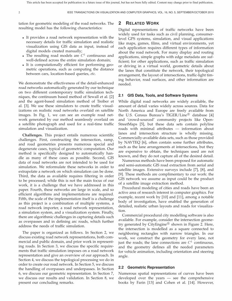
(a) An overhead view of a highway interchange withoverpasses. The highways are colored to show the ar-rangement computed by our method.
(b) A view of the blue highway, which is given the greatestheight.
Fig. 4. A highway interchange with overpasses generatedby our method.
5 OVERPASSES AND UNDERPASSES
Another feature of real road networks is the presenceof overpasses and underpasses, including the complexweaving of roads at multi-highway interchanges. Whileit is only necessary to capture the topological relation-ships between these roads for current traffic simulationformulations (as traffic simulations only take place in1D), a reasonable method for estimating road heightsis needed for 3D modeling. These height calculationscan be done following the procedures described above,resulting in overpasses as shown in Figure 4.
We assume that underpasses and overpasses are rep-resented in the GIS data by roads that contain linesegments that intersect but have no shared nodes. Inother words, the overpasses are represented implicitly,and the point of intersection must be calculated fromthe data.
5.1 Intersection Points
The problem of calculating intersection points amongline segments lacking any structure is well-studied incomputational geometry, with optimal algorithms beingO(N logN+K) where N is the number of line segmentsand K is the number of intersecting points [20]. Thesealgorithms typically consider segments with shared end-points to be colliding, which is not a desired assumptionfor our application. To handle this, every road segmentof every road can be truncated by ε to avoid theseintersections being found, or a post-processing step can
be done to discard all intersections for which the onlyintersecting segments are neighbors.
5.2 Road Height LevelsOnce the intersection points have been either givenor found, the road heights at those points need to bedetermined. In simple cases, one road will be aboveand one below. The specific order might be given in themetadata. In general, however, there could be multiplelevels of overpasses. Our method divides the overpassesinto levels with the goal of having the smallest numberof roads elevated, as would be the most cost-efficientapproach for a real road system.
We consider the k intersection points and their corre-sponding roads. As a pre-processing step, we first divideevery road into multiple sets such that (1) no roadintersects itself and (2) no two intersections on a road areseparated by a distance greater than δ. The reason for (1)is so that we can consider every road as being on a singlelevel, and the reason for (2) is that intersections thatare separated by a large distance should be consideredindependently.
Given the above, our proposed method is to generatethe set of conflicting roads, C, for each road with an in-tersection. The roads are then sorted by |C| in ascendingorder3 and placed in a priority queue Q1. For the ith stepof the algorithm, we build level i: until Qi is empty, weremove the road j with the smallest |Cj |. This road is setto level i. For every road c in Cj , we remove c from Qi,and add it to Qi+1. When Qi is empty, the loop repeatsfor Qi+1 until no roads remain.
The result of this loop is that all the roads that don’tconflict with one another are placed on the same level,and the levels are ordered such that those roads thatconflict with the greatest number of other roads areplaced at higher levels: this is a greedy approach tocreate levels that have fewer roads the higher the level.
6 GEOMETRIC MODELING OF ROAD NET-WORKS: ARC ROADS
Most digital maps use polylines — C0 series of line seg-ments — to represent road shapes. However, real-worldroads are curved, and these polylines visibly deviatefrom the real shape of the road and give the road anangular shape. Furthermore, linear segments generallylead to visible artifacts in the motion of vehicles alongthese roads: the sudden change in direction between seg-ments produces large instantaneous changes in vehicleorientation, in violation of car kinematics. Figure 6(a)shows a polyline-based road imported from GIS data.
Given the true curve of the underlying road, one couldsimply refine the approximation of the underlying curve
3. We can also add meta data into the sorting procedure. Forexample, if we wanted highways to be underpasses wherever possible,we could add road type as a tie-breaker in the sort.
This article has been accepted for publication in a future issue of this journal, but has not been fully edited. Content may change prior to final publication.

WILKIE et al.: TRANSFORMING GIS DATA INTO FUNCTIONAL ROAD MODELS FOR LARGE-SCALE TRAFFIC SIMULATION 9
(a) A large scene featuring two towns and a highway. (b) An overpass created with our method and proceduralmodeling.
(c) A suburban neighborhood road network created byour method and aligned with a satellite image.
(d) A divided highway with two ramps created by ourmethod.
Fig. 5. A collection of road networks, all generated by our method. The traffic in these figures was simulated using thetechnique of [2]
by adding more straight line segments. This can giveacceptable results in certain cases, although it leads toa proliferation of data points. However, barring extremelevels of refinement, the C0 nature of the representationis still observable, and it should also be noted that thereis no clear method by which to use polylines in threedimensions to describe vehicle motion with consistentorientation. However, we have only the polylines in theinput GIS data set to work with and lack informationneeded for such refinement.
Numerous techniques have been proposed for fittingcurves to polyline road data and for the refinement andsmoothing of these curves [21], [22], [23], [24]. Thesemethods are useful for visual description, but can becomputational obstacles for simulation. For example,splines are frequently costly to compute with. B-splineshave no general closed form for arc-length and requirenumerical quadrature to evaluate. Traffic simulationtechniques frequently represent vehicles’ positions alongroads parametrically. To advance the position of vehiclesalong roads, information about velocity is integratedinto position and translated into parametric space; todisplay vehicles’ locations, this parametric information
is translated into a point x in R3. This process can
occur multiple times per vehicle per simulation step, andwhen it requires quadrature, its expense can dominateruntimes.
As an alternative, we propose arc roads, which consistof alternating straight line segments and circular arcs.This representation has numerous advantages over poly-lines:
• The curve is C1.• It is well-defined in three dimensions and suitable
for traffic simulation — a consistent Frenet framedefining ‘forward’, ‘up’, and ‘right’ is available ateach point.
• It is straightforward to derive from existing polylinedata.
• It admits a simple and inexpensive parametrization.• It allows efficient computation of vehicle position
and orientation.• It enables much smoother animations of vehicle
motion.
Figure 6(b) shows an exemplary arc road derived fromthe polyline shown in Figure 6(a). Arc roads are particu-larly suitable for describing vehicle motion; the turning
This article has been accepted for publication in a future issue of this journal, but has not been fully edited. Content may change prior to final publication.

10 IEEE TRANSACTIONS ON VISUALIZATION AND COMPUTER GRAPHICS, VOL. 16, NO. 5, SEPTEMBER/OCTOBER 2010
(a) Polyline road geometry (imported from the TIGER R©
database [4] via OpenStreetMap [5] )
(b) An arc road derived from the above polyline. Theorange arcs show the center and radius of each arc usedto give the road its smooth appearance.
Fig. 6. A polyline and derived arc road
behavior it prescribes matches the kinematic model ofthe simple car [25].
6.1 Arc FormulationWe have an ordered sequence P of n points:
P := (p0, p1, . . . , pn−2, pn−1) (1)
These points define a polyline, which is not necessarilyplanar, with n− 1 segments such as that in Figure 6(a).Assume, without loss of generality, that there are notwo points adjacent in the sequence that are equal, andthat there are no three adjacent points that are collinear;we wish to smooth this polyline to what is shown inFigure 6(b), which we shall refer to as PS . We constructPS by replacing the region around each interior pointpi of P with a circular arc and retaining the exteriorpoints p0 and pn−1. Each of these circular arcs can becharacterized by a center ci, radius ri, orientation oi, startradius direction si, and angle φi; see Figure 7. Each arci corresponds to an interior point pi, and we require itto be tangent to pi−1pi and pipi+1.
To help describe each arc i, we introduce the followingquantities derived from the polyline P :
vi = pi+1 − pi (2)Li = |vi| (3)
ni =vi
Li=
vi
|vi| (4)
Fig. 7. The quantities defining an arc i corresponding tointerior point pi. The orientation vector oi is coming out ofthe page.
These are: vectors from point pi+1 to point pi (Eq. (2)),the vector lengths (Eq. (3)), and associated unit vectors(Eq. (4)), respectively. We will also refer to −ni−1 =pi−1−pi
|pi−1−pi| and to the normal of the plane containing thecircle,
oi = −ni−1 × ni (5)
At certain times, it is useful to construct a matrix Fi thatdescribes the axes defined by ni, si, and oi:
Fi =[ni si oi
](6)
Parametrization: Arc roads admit straightforwardparametrizations Ps(t) = �x because their lengths aresimple to compute. They are simply the length of theoriginal polyline P adjusted by the difference betweeneach arc and the ‘corner’ of the polyline it replaces.Just as with a polyline, parametrization operations canbe accelerated by storing the cumulative length of eachsegment and arc. Binary search can then be used to findthe relevant length for a given t. This is considerablyless compute-intensive than performing quadrature todetermine lengths, as is necessary for many spline rep-resentation.
Speed limit estimation: Where input GIS data lacksdetail about speed limits, arc roads can be used toestimate speed limits:
vmax =√gμsr (7)
Here g is acceleration due to gravity, μs the coefficientof static friction, and r the radius (of a given arc) —vmax is the highest velocity achievable on the arc withoutslipping; safe speed limits should be proportional to thisvalue to meet the road safety requirements.
6.2 Fitting arc roads to polylines
Given an arbitrary polyline P , it is desirable to auto-matically select the ri to complete the definition of a C1
This article has been accepted for publication in a future issue of this journal, but has not been fully edited. Content may change prior to final publication.

WILKIE et al.: TRANSFORMING GIS DATA INTO FUNCTIONAL ROAD MODELS FOR LARGE-SCALE TRAFFIC SIMULATION 11
smoothed polyline PS . A reasonable goal is to pick theri such that the quantity
mini∈[1,n−2]
ri (8)
is maximal over all valid configurations of ri; this helpsminimize the ‘sharpness’ of each corner.
We have developed a recursive algorithm for selectingthe ri for each arc given a polyline P that satisfiesEquation (8). Briefly, we iterate over all of the segmentspipi+1, i ∈ [0, n − 2] and consider how large a radius itis possible to assign to the arcs i, i + 1 at either end ofthe segment i; we take the smallest such radius over allconsidered segments and assign it to the associated arcs.This process is repeated recursively until each interiorpoint has been assigned a radius value.
In the interest of space, we have omitted the detailsof the algorithm; a complete description and proof of itsoptimality in satisfying Equation 8 is given in [26].
6.3 Offset polylines
It is natural to consider roads as 2-dimensional surfacesin 3-dimensional space. The arc road formulation abovedescribes 1-dimensional curves — we can define such a2-dimensional surface by ‘offsetting’ the curve in a givendirection. That is, we consider a new curve P ′
S is ‘offset’from PS to one side by a signed distance d; see Fig. 8.P ′S that has the property that at every point, the nearest
point on PS is exactly distance d away. We have usedthe convention that d > 0 refers to a ‘right’ offset (thelower blue line in Fig. 8) and d < 0 to a ‘left’ offset(the upper blue line in the same figure). The new arcs i
Fig. 8. A ‘fattened’ arc road; the original arc road PS
as computed above is drawn in black. The blue linesrepresent the same shape offset to either side by an equaldistance.
corresponding to P ′S (with signed offset d) can be derived
from PS by replacing each ri with ri + d.New endpoints p′0 and p′n−1 must be established for
this line. A reasonable definition is use the plane of thefirst and last arcs to choose perpendiculars suitable forplacing these offset endpoints, resulting in,
p′0 = p0 + d(n0 × o1) (9)p′n−1 = pn−1 + d(nn−2 × on−1 (10)
(a) P ∗: A polyline approximation of an arcroad PS
(b) A triangle mesh approximation of a‘fattened’ arc road PS
Fig. 9. Discrete approximations of arc roads
6.4 Discrete approximations of arc roadsTo visually depict an arc road, we may wish to computea discrete representation.
6.4.1 PolylinesOne way to do this is by approximating the shape by aseries of segments, a new polyline P ∗. See Figure 9(a).Each arc i must be approximated with a sequence Γi ofqi ∈ Z>1 connected points. Then the sequence of pointsin P ∗ is simply:
P ∗S =
(p0,Γ
01, . . . ,Γ
q1−11 , . . . ,Γ0
n−2, . . . ,Γqn−2−1n−2 , pn−1
)(11)
Each Γi is generated by rotating and scaling the frameFi (from Equation (6)) of each arc incrementally andtranslating by the center ci,
Γji = ci + riFi
[cos tj , sin tj , 0
]T, j ∈ Z[0, qi − 1] (12)
Here the tj are the elements of a sequence[0, φi/(qi − 1), 2φi/(qi − 1), . . . , φi] of length qi.
6.4.2 Triangle meshesA surface representation of an arc road can be easilycomputed from a pair of offset arc roads (computed asin Sec. 6.3). Given an arc road PS and two polylinesoffset from PS , order the polylines by offset so that wehave a ‘left’ polyline P l
S and a ‘right’ polyline P rS . Now
we can use any constrained triangulation technique to
This article has been accepted for publication in a future issue of this journal, but has not been fully edited. Content may change prior to final publication.

12 IEEE TRANSACTIONS ON VISUALIZATION AND COMPUTER GRAPHICS, VOL. 16, NO. 5, SEPTEMBER/OCTOBER 2010
compute a planar triangle mesh with P lS and P r
S as theboundaries; see Figure 9(b).
6.5 Road mesh geometryIn Sec. 6.4, we show how to construct a mesh for a pairof given offsets. To create geometry for roads, we needonly compute the width of each road — this is easilydone by examining the position of each member lane ofa given road: the position of the left edge of leftmostmember lane forms the left offset, and the position ofthe right edge of the rightmost member lane forms theright offset.
Our data structure allows for the member lanes of aroad to vary along its length; in the case, we simplyextract a mesh for each parametric interval along theroad that has a constant arrangement of member lanes.
7 RESULTS
We have implemented our method described in thispaper. In Figure 5, we show some example road net-works created by our technique used in real-time trafficsimulation. The models illustrated here were createdusing GIS data from the Open Street Map website. Thefirst image, Figure 5(a), shows a large road networkcreated within only a few seconds by our method. Thenetwork features two small towns in North Carolina,Biscoe and Star, connected by a highway with multipleoverpasses and ramps. Figure 5(b) shows a highwayoverpass that was created using our GIS processingand 3D procedural modeling. Figure 5(c) shows a roadnetwork created by our method from GIS data overlaidon top of a satellite image. Notice the degree to which theroads align, despite the fact that the original data is C0
polylines. Figure 5(d) shows another road representationcreated by our method and overlaid on a satellite image.This map is from another set of highways with an on-ramp and an off-ramp. Note that the ramps C1 smoothlyconnect to the highway, enabling simulated cars to mergeonto and off of the highway seamlessly, given the inputpolyline data not suitable for traffic simulation. This isalso shown in the sequence of images in Figure 10, whichshow an on-ramp and off-ramp to a highway from aboveat a decreasing height.
As shown in Figure 5(a), 5(c) and 5(d), the seamlessalignment between the large-scale road networks in thesatellite images and the models created directly fromGIS data using our method provides a convincing visualvalidation of our technique. The functional validity ofthe road networks created by our algorithm is furtherdemonstrated by the successful real-time traffic simula-tions on the road networks generated from real-worldGIS data, with the resulting visual simulations mappedback to the original satellite images showing no notice-able artifacts in the simulated traffic flows. The videoclips for the real-time traffic simulations using the roadnetwork models created by our method, as shown inFigure 5(a) to Figure 5(d), can be found at:
http://gamma.cs.unc.edu/RoadNetwork.
8 CONCLUSION
We have presented a method for transforming GIS datainto a topological and geometric representation suitablefor use in traffic simulation. Our geometric represen-tation of roads is visually smooth, including at rampsand intersections. Our method preserves the topologicalrelationships of the GIS road network. We have shownexamples of GIS data that have been processed by ourmethod and composed with satellite images. These fig-ures illustrate features of the road networks generated byour method, such as intersection handling and highwayramps, as well as the extensive scale of models that ourmethod can process within a matter of few seconds.
ACKNOWLEDGMENTS
This research is supported in part by Army ResearchOffice, National Science Foundation, and RDECOM.
REFERENCES
[1] D. Helbing, “Traffic and related self-driven many-particle sys-tems,” Reviews of Modern Physics, vol. 73, no. 4, pp. 1067–1141,2001.
[2] J. Sewall, D. Wilkie, P. Merrell, and M. Lin, “Continuum TrafficSimulation,” in Computer Graphics Forum, vol. 29, no. 2. BlackwellPublishing, 2010, pp. 439–448, (Proceedings of Eurographics 2010).
[3] M. Treiber, A. Hennecke, and D. Helbing, “Congested traffic statesin empirical observations and microscopic simulations,” PhysicalReview E, vol. 62, no. 2, pp. 1805–1824, 2000.
[4] U.S. Census Bureau, “TIGER/Line R©,” 2010. [Online]. Available:http://www.census.gov/geo/www/tiger/
[5] OpenStreetMap community, “OpenStreetMap,” 2010. [Online].Available: http://www.openstreetmap.org/
[6] NAVTEQ, “NAVTEQ,” 2010. [Online]. Available: http://www.navteq.com/
[7] J. Mena, “State of the art on automatic road extraction for gisupdate: a novel classification,” Pattern Recognition Letters, vol. 24,pp. 3037–3058, 2003.
[8] J. Park, R. Saleh, and Y. Yeu, “Comprehensive survey of extrac-tion techniques of linear features from remote sensing imageryfor updating road spatial databases,” in ASPRS-ACSM AnnualConference and FIG XXII Congress, 2002.
[9] A. Fortier, D. Ziou, C. Armenakis, and S. Wang, “Survey ofwork on road extraction in aerial and satellite images,” Center forTopographic Information Geomatics, Ontario, Canada. Technical Report,vol. 241, 1999.
[10] E. Galin, A. Peytavie, N. Marechal, and E. Guerin, “ProceduralGeneration of Roads,” in Computer Graphics Forum, vol. 29, no. 2.Wiley Online Library, 2010, pp. 429–438, (Proceedings of Euro-graphics 2010).
[11] G. Chen, G. Esch, P. Wonka, P. Mueller, and E. Zhang, “Interactiveprocedural street modeling,” in SIGGRAPH 2008. New York, NY,USA: ACM, 2008.
[12] Prodecural Inc., “CityEngine Manual,” February2011. [Online]. Available: http://www.procedural.com:8080/help/topic/com.procedural.cityengine.help/html/manual/is/create/streetshapes.html
[13] G. Farin, Curves and Surfaces for Computer-Aided Geometric Design:A Practical Code. Academic Press, Inc. Orlando, FL, USA, 1996.
[14] E. Cohen, R. Riesenfeld, and G. Elber, Geometric modeling withsplines: an introduction. AK Peters Ltd, 2001.
[15] L. Piegl and W. Tiller, The NURBS book. Springer Verlag, 1997.[16] P. Willemsen, J. Kearney, and H. Wang, “Ribbon networks for
modeling navigable paths of autonomous agents in virtual envi-ronments,” IEEE Transactions on Visualization and Computer Graph-ics, pp. 331–342, 2006.
This article has been accepted for publication in a future issue of this journal, but has not been fully edited. Content may change prior to final publication.

WILKIE et al.: TRANSFORMING GIS DATA INTO FUNCTIONAL ROAD MODELS FOR LARGE-SCALE TRAFFIC SIMULATION 13
Fig. 10. A series of images showing ramps smoothly connected to a highway, at a variety of scales
[17] H. Wang, J. Kearney, and K. Atkinson, “Arc-length parameterizedspline curves for real-time simulation,” in Proc. 5th InternationalConference on Curves and Surfaces. Citeseer, 2002, pp. 387–396.
[18] J. van den Berg and M. Overmars, “Kinodynamic motion plan-ning on roadmaps in dynamic environments,” in Proceedings ofthe 2007 IEEE/RSJ International Conference on Intelligent Robots andSystems, San Diego, CA, November 2007, pp. 4253–4258.
[19] D. Nieuwenhuisen, A. Kamphuis, M. Mooijekind, and M. Over-mars, “Automatic construction of roadmaps for path planning ingames,” in Proceedings of the International Conferefence on ComputerGames, Artificial Intelligence, Design and Education, 2004, pp. 285–292.
[20] I. Balaban, “An optimal algorithm for finding segments intersec-tions,” in Proceedings of the eleventh annual symposium on Computa-tional geometry. ACM, 1995, p. 219.
[21] R. McMaster, “Automated line generalization,” Cartographica: TheInternational Journal for Geographic Information and Geovisualization,vol. 24, no. 2, pp. 74–111, 1987.
[22] J. Ware, C. Jones, and N. Thomas, “Automated map generalizationwith multiple operators: a simulated annealing approach,” Inter-national Journal of Geographical Information Science, vol. 17, no. 8,pp. 743–769, 2003.
[23] D. Burghardt, “Controlled line smoothing by snakes,” GeoInfor-matica, vol. 9, no. 3, pp. 237–252, 2005.
[24] M. Harrower and M. Bloch, “MapShaper. org: A map general-ization web service,” Computer Graphics and Applications, IEEE,vol. 26, no. 4, pp. 22–27, 2006.
[25] S. M. LaValle, Planning Algorithms. Cambridge University Press,2006.
[26] J. Sewall, “Efficient, scalable traffic and compressible fluid simu-lations using hyperbolic models,” Ph.D. dissertation, Universityof North Carolina at Chapel Hill, 2010.
David Wilkie received a BS in computer sci-ence from Drexel University. He is currently inthe doctoral program at the University of NorthCarolina at Chapel Hill, Department of Com-puter Science. He is a research assistant inthe GAMMA group, and prior to that he wasa research assistant in the GICL laboratory atDrexel University. David’s research interests in-clude motion planning, geometric modeling, andintelligent transportation systems.
Jason Sewall received his BA in Mathematicsand BS in Computer Science from the Universityof Maine and his MS and PhD from the Uni-versity of North Carolina at Chapel Hill. Whileat UNC-Chapel Hill, he worked on physically-based modeling problems under the supervisionof Prof. Ming Lin. Jason joined the Parallel Com-puting Lab at Intel in 2010 as a Research Sci-entist. His research interests include graphics,physically-based modeling, scientific computa-tions, parallel computing, and algorithms.
This article has been accepted for publication in a future issue of this journal, but has not been fully edited. Content may change prior to final publication.

14 IEEE TRANSACTIONS ON VISUALIZATION AND COMPUTER GRAPHICS, VOL. 16, NO. 5, SEPTEMBER/OCTOBER 2010
Ming C. Lin received her B.S., M.S., and Ph.D.degrees in Electrical Engineering and ComputerScience from the University of California, Berke-ley. She is current the John R. & Louise S.Parker Distinguished Professor of Computer Sci-ence at the University of North Carolina (UNC),Chapel Hill. She has received several honorsand awards, including the NSF Young FacultyCareer Award in 1995, UNC Hettleman Awardfor Scholarly Achievements in 2002, Beverly W.Long Distinguished Term Professor 2007-2010,
Carolina Women’s Center Faculty Scholar in 2008, Carolina’s WOWSScholar 2009-2011, IEEE VGTC VR Technical Achievement Award2010, and 8 best paper awards. Her research interests include computergraphics, visualization, robotics, and human-computer interaction ingeneral with a focus on physically-based modeling, real-time interactionwith virtual environments, geometric modeling, and GPU-Computing.She has (co-) authored more than 220 refereed publications and co-edited/authored four books. She is the Editor-in-Chief of IEEE Transac-tions on Visualization and Computer Graphics and a member of six ed-itorial boards of scientific journals. She has served as a program/papercommittee member for over 100 leading conferences and co-chairedover 20 international conferences and workshops. She also has servedon the Steering Committees of international conferences and advisoryboards for government agencies and industry.
This article has been accepted for publication in a future issue of this journal, but has not been fully edited. Content may change prior to final publication.