ifatca the controller - october 1962
DESCRIPTION
ÂTRANSCRIPT
-------10 Or----
D 0
----....jO>----
TELEFUNKEN radar for safe
guidance from take-off to
landing
TELEFUNKEN
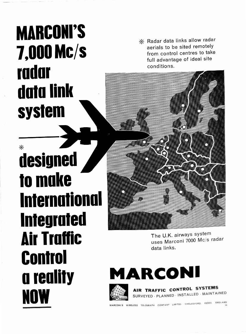
MARCON I'S 7,000Mc/s rod or doto link system
* designed to moke lnternotionol lnteuroted Air Troftic Control o reolity NOW
* Radar data links allow radar aerials to be sited remotely from control centres to take full advantage of ideal site conditions.
The U.K. airways system uses Marconi 7000 Mc/s radar
data l inks.
MARCONI .~
AIR TRAFFIC CONTROL SYSTEMS
MARCONl 'S WIRELESS TELEGR APH COMPANY LIMITED CHELMSFORD ESSEX ENGLAND so

Sat co
Efficient transport means prosperity
Satco comprises the ground equipment to predict, coordinate, check and display the movements of air traffic en route and in terminal areas. It provides an extremely rapid method of calculating flight paths, for assessing potential conflicts and for coordination between Area Control Centres. Special features are included for military / ci vil coordination and for the control of jetpowered traffic.
The system has been ordered by The Netherlands Government and the first phase is in operational use.
Signaal N.V. HOLLAN DSE SIGNAALAPPARATEN - HENGELO - NETHERLANDS
-~- -- --~-~-- -
IFATCA JOURNAL OF AIR TRAFFIC CONTROL
THE CONTROLLER Frankfurt am Main, October 1962 Volume 1 · No. 4
Publisher: International Federation of Air Traffic Con· !rollers' Associations, Cologne· Wahn Airport, Germany.
Elective Officers of IFATCA: L. N. Tekstra, President; Maurice Cerf, First Vice President; Roger Sade!, Second Vice President; Hans W. Thau, Secretary; Henning Throne, Treasurer; Walter Endlich, Editor.
Editor: Walter H. Endlich, 6 Frankfurt am Main 1, Raimundstrasse 147, Phone 20821 or 521710.
Production and Advertising Sales Office: W.Kramer&Co., 6 Frankfurt am Main NO 14, Barnheimer Landwehr 57a, Phone 44325, Postscheckkonto Frankfurt am Main 11727. Rate Card Nr. 1.
Printed by: W.Kramer&Co.,6 Frankfurt am Main N014, Bornheimer Landwehr 57a.
Subscription Rate: DM 8,- per annum (in Germany).
Contributors are expressing thei_r personal points of view and opinions, which must not necessarily coincide with those of the International Federation of Air Traffic Controllers' Assaciatians (IFATCA).
IFATCA docs not assume responsibility for statements made and opinions expressed, it does only accept responsibility for publishing these contributions.
Contributions are welcome as are comments and criticism. No payment can be made for monuscripts submitted for publication in "The Controller". The Editor reserves the right to make any editorial changes in manuscripts, which he believes will improve the material without altering the intended meaning.
Written permission by the Editor is necessary for reprinting any part of this Journal.
Advertisers in this Issue: The Decca Navigator Company, Ltd. (Inside Bock Cover). Flughofen Frankfurt/Main AG (34). General Prescision Incorporated (33). Gilfillan Corporation (Bock Cover). Marconi"s Wireles Telegraph Company (1, 4). Hollondse Signoolapparoten N. V. (2). Standart Elektrik Lorenz (35). Telefunken GmbH (Inside Front Cover).
Picture Credit: British Features (27, 28, 29, 30, 31, 32). Hazeltine Corporation (22, 23, 25, 26). Marconi (5, 6, 8, 9, 10). Dr.-!ng. Zelzmonn (15, 16, 17, 18, 19, 20).
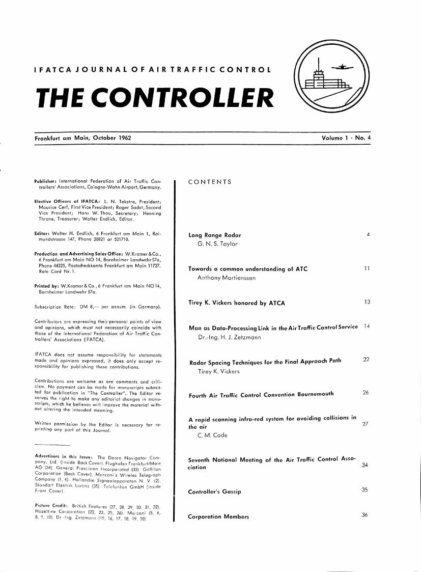
CONTENTS
Long Range Radar
G. N. S. Taylor
Towards a common understanding of ATC
Anthony Martienssen
Tlrey K. Vickers honored by ATCA
Man as Data-Processing Link in the Air Traffic Control Service
Dr.-lng. H.J. Zetzmann
Radar Spacing Techniques for the Final Approach Path
Tirey K. Vickers
Fourth Air Traffic Control Convention Bournemouth
A rapid scanning infra-red system for avoiding collisions in the air
C. M. Cade
Seventh National Meeting of the Air Traffic Control Association
Controller's Gossip
Corporation Members
4
11
13
14
22
26
27
34
35
36
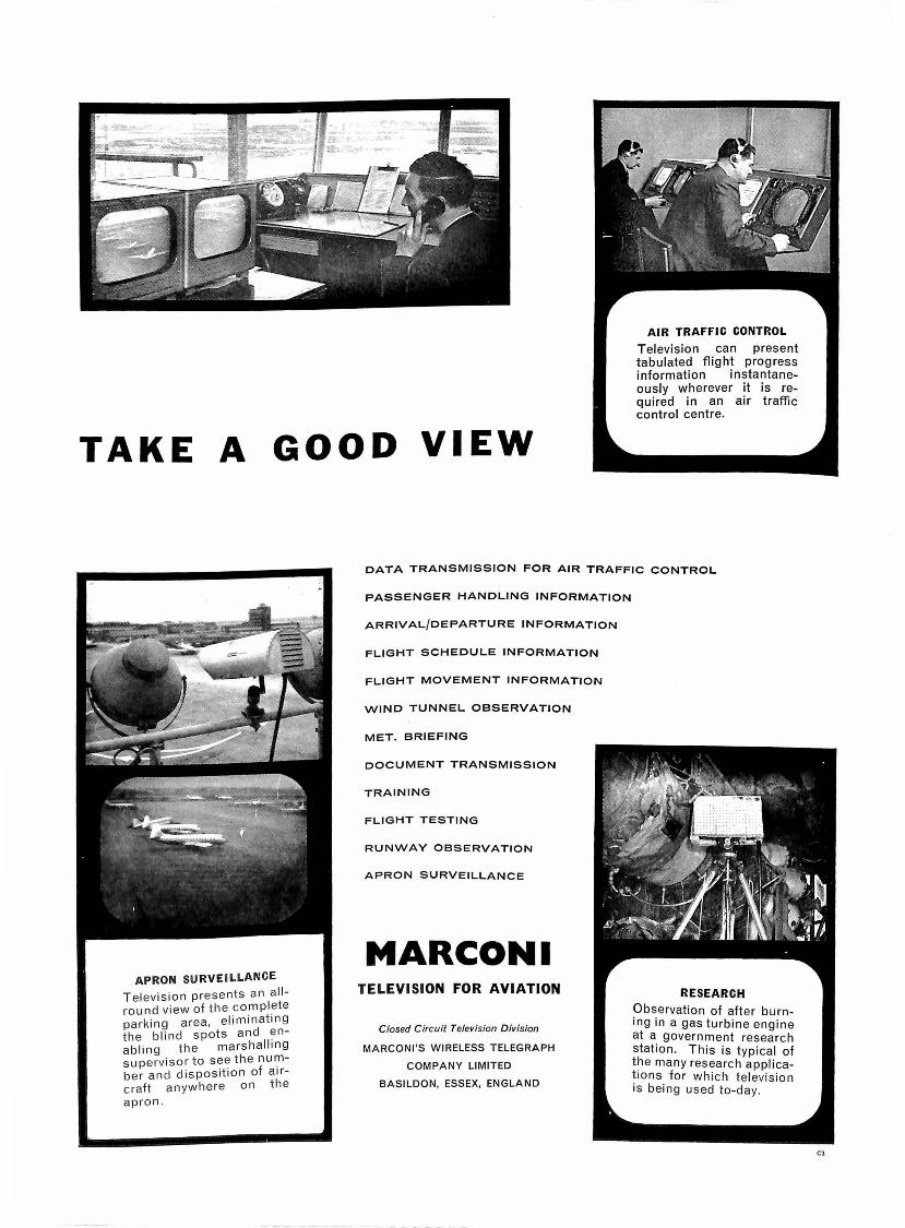
AIR TRAFFIC CONTROL
Television can present tabulated flight progress information instantaneously wherever it is required in an air traffic control centre.
TAKE A GOOD VIEW
APRON SURVEILLANCE
Television presents an allround view of the comp lete parking area, eliminating the b lin d spots and enab ling the marshalling supervisor to see the number and dispos1t1on of airc raft an ywhere on t he apron .
DATA TRANSMISSION FOR AIR TRAFFIC CONTROL
PASSENGER HANDLING INFORMATION
ARRIVAL/DEPARTURE INFORMATION
FLIGHT SCHEDULE INFORMATION
FLIGHT MOVEMENT INFORMATION
WIND TUNNEL OBSERVATION
MET. BRIEFING
DOCUMENT TRANSMISSION
TRAINING
FLIGHT TESTING
RUNWAY OBSERVATION
APRON SURVEILLANCE
MARCONI TELEVISION FOR AVIATION
Closed Circuit Television Division
MARCONl'S WIRELESS TELEGRAPH
COMPANY LIMITED
BASILDON, ESSEX, ENGLAND
RESEARCH
Observation of after burning in a gas turbine engine at a government research station. This is typ ical of the many research applications for which television is being used to-day.
Cl
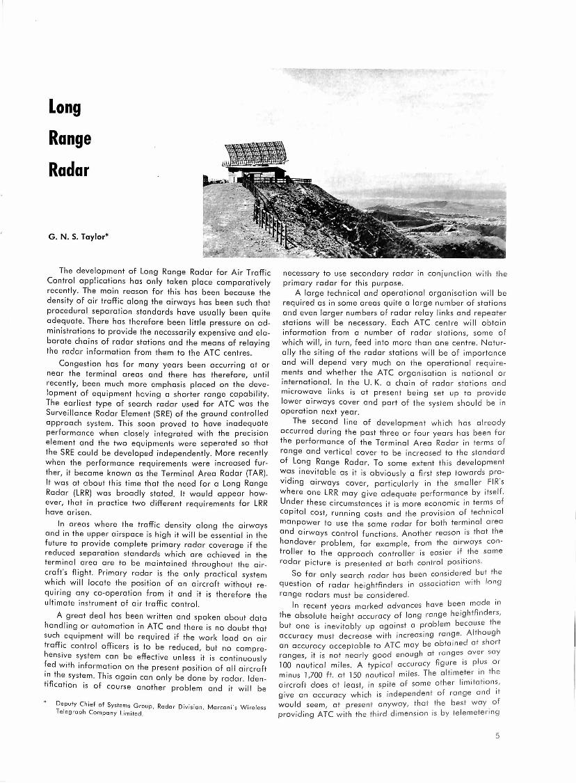
Long
Range
Radar
G. N. S. Taylor*
The development of Long Range Radar for Air Traffic Control applications has only taken place comparatively recently. The main reason for this has been because the density of air traffic along the airways has been such that procedural separation standards have usually been quite adequate. There has therefore been little pressure on administrations to provide the necessarily expensive and elaborate chains of radar stations and the means of relaying the radar information from them to the ATC centres.
Congestion has for many years been occurring at or near the terminal areas and there has therefore, until recently, been much more emphasis placed on the development of equipment having a shorter range capability. The earliest type of search radar used for ATC was the Surveillance Radar Element (SRE) of the ground controlled approach system. This soon proved to have inadequate performance when closely integrated with the precision element and the two equipments were seperated so that the SRE could be developed independently. More recently when the performance requirements were increased further, it became known as the Terminal Area Radar (TAR). It was at about this time that the need for a Long Range Radar (LRR) was broadly stated. It would appear however, that in practice two different requirements for LRR have arisen.
In areas where the traffic density along the airways and in the upper airspace is high it will be essential in the future to provide complete primary radar coverage if the reduced separation standards which are achieved in the terminal area are to be maintained throughout the aircraft 's flight . Primary radar is the only practical system which will locate the position of an aircraft without requiring any co-operation from it and it is therefore the ultimate instrument of air traffic control.
A great deal has been written and spoken about data handling or automation in ATC and there is no doubt that such equipment will be requ·ired if the work load on air traffi.c control officers is to be reduced, but no comprehens1~e s.ystem can be effective unless it is continuously fed with information on the present position of all aircraft in the system. This again can only be done by radar. Identification is of course another problem and it will be
Deputy Chief of Systems Group , Rada r D iv ision , Marconi ·s Wire less Telegraph Company Limited.
necessary to use secondary rada r in conjunction w i th the primary radar for this purpose.
A large technical and operational organisation will be required as in some areas quite a large number of stations and even larger numbers of radar relay links and repeater staiions will be necessary. Each ATC centre will obtain information from a number of radar stations, some o f which will, in turn, feed into more than one centre . Naturally the siting of the radar stations will be of importance and will depend very much on the operational requirements and whether the ATC organisation is national o r international. In the U. K. a chain of radar stations and microwave links is at present being set up to provide lower airways cover and part of the system should be in operation next year.
The second line of development which has already occurred during the past three or four years has been fo r the performance of the Terminal Area Radar in term s of range and vertical cover to be increased to the standard of Long Range Radar. To some extent this development was inevitable as it is obviously a first step towards providing airways cover, particularly in the smaller FIR 's where one LRR may give adequate performance by itself. Under these circumstances it is more economic in term s of capital cost, running costs and the provision of technical manpower to use the same radar for both terminal area and airways control functions. Another reason is that the handover problem, for example, from the airways controller to the approach control !er is easier if the same radar picture is presented at both contro l positions.
So far only search radar has been considered bu t the question of radar heightflnders in associ ation with lon g
range radars must be conside1·ed . In recent years marked advances have been made in
the absolute height accu racy of long range heightfinders, but one is inevitably up against a problem because th e accuracy must decrease with increasing range . Al though an accuracy acceptable to ATC may be obtained at sho r t ranges, it is not nearly good enough at ranges. over say 100 nautical miles. A typical accuracy figure is p lus 0 1· minus 1,700 ft. at 150 nautical miles . The altimeter in the aircraft does at least, in spite of some other limi ta t ion s, give an accuracy which is independent of ra nge and it would seem, at presen t anyway, tha t th e b es t w ay of providing ATC with the th ird d imen sion is by te lemetering
5
the altimeter reading from each aircraft over the secondary radar system.
Having broadly stated the main uses of long range radar how does one define the technical parameters of the equipment? This is a much more difficult problem as there are as yet no standard parameters which are accepted universally. Any radar system is a mass of compromises ond as operational requirements differ from one administrat ion to another it is inevitable that some will prefer a different compromise to others. Again, manufacturers generally design their equipment to have what they consider to be the best compromises to suit their particular market. The administration wishing to buy equipment has therefore the problem of selecting the particular product which he thinks comes nearest to his requirements. This is by no means easy as the definitions of radar performance are at present much too loose and therefore open to a wide divergence of interpretation. In addition the methods of performance measurement are too subjective to be very accurate.
9. Ease of modification to give a long life to the equipment by allowing new developments to be added to keep it up to date.
All these are simple and straightforward and the majority would apply to any form of ATC equipment.
It is when one comes to the more detailed technical parameters that the problems arise. Some of these parameters must be firmly laid down, others can be left for the radar designer to choose, most of them are interrelated to a greater of lesser degree.
These technical parameters are:
l . Overall coverage. 2. Pulse Recurrence Frequency. 3. Peak Transmitter power. 4. Transmitter Pulse Length. 5. Wavelength.
6. Aerial size (i . e. horizontal and vertical beamwidths) . 7. Aerial rotation speed.
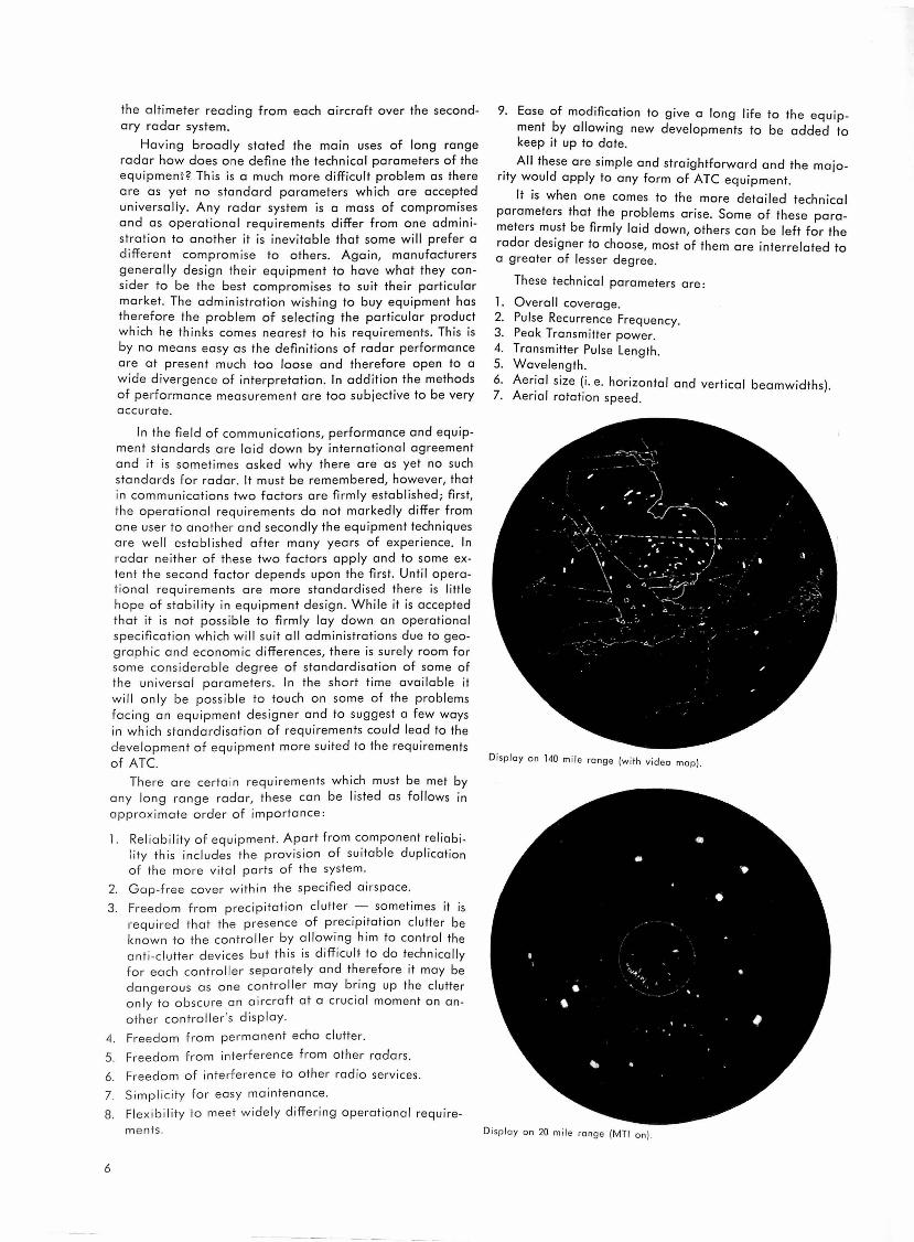
In the field of communications, performance and equipment standards are laid down by international agreement and it is sometimes asked why there are as yet no such standards for radar. It must be remembered, however, that in communications two factors are firmly established; first, the operational requirements do not markedly differ from one user to another and secondly the equipment techniques are well established after many years of experience. In radar neither of these two factors apply and to some extent the second factor depends upon the first. Until operational requirements are more standardised there is little hope of stability in equipment design . While it is accepted that it is not possible to firmly lay down an operational specification which will suit all admin istrations due to geographic and economic differences, there is surely room for some considerable degree of standardisation of some of the universal parameters. In the short time ava i lable it will only be possible to touch on some of the problems facing an equipment designer and to suggest a few ways in which standardisation of requirements could lead to the deve lopme nt of equipment more suited to the requirements of A TC. Display an 140 mile range (with v ideo map).
There are certa in requirements which must be met by any long range radar, these can be listed as follows in approximate order of importance :
l . Reliability of equipment. Apart from component reliabi lity thi s includes the provision of suitable duplication of th e more vita l parts of the system .
2. G ap-free cover w ithin the specified ai rs pace.
3. Freedom from precipitation clutter - sometimes it is required that the presence of precipitation clutter be known to the controll er by allowing him to control the anti-clu tter devices but this is difficult to do technically for each controller separately and therefore it may be dangerous as one controller may bring up the clutter only to obscure an aircraft at a crucial moment on an
other controller's d isp lay.
4. Freedom from permanent echo clutter.
5. Freedom from interference from other radars .
6. Freedom of interference to other radio services.
7. Simp l ic ity for easy maintenance.
8. Fl exibi li ty to meet wide ly differing operational require
ments .
6
Di sp lay on 20 mile range (MTI on) .

Overall coverage may be stated by the equipment designer and manufacturer or may be specified by the user. Over the past few years a large number of specifications for Long Range Radar and extended Terminal Area Radar have been issued by various administrations. These have called for ranges varying from 70 nautical miles to 200 nautical miles. Aircraft echoing areas for which these ranges must be achieved vary from l square metre to 15 square metres or sometimes are specified as a "medium transport". Maximum heights vary from 30,000 to 100,000 ft. The low cover requirement varies from a realistic one which takes some account of the shape of the bottom edge of the radiation pattern from an aerial to a somewhat unrealistic one where radiation is required to reach down to one fifth of a degree at the maximum range. In some cases the vertical cover requirement is shown diagramatically with an apparently flat earth. The top angle of the cover varies from 20 degrees to, in one case, 90 degrees.
It would certainly simplify the radar designer's problems if a standard aircraft echoing area be specified on all cover diagrams. A figure of 10 square metres has been fairly widely accepted in the past but with the advent of joint civil and military control of the upper airspace it may well be more convenient to specify a smaller figure such as 2 or 3 square metres.
Maximum range and altitude are more difficult to standardise as they depend upon local air traffic problem. As the maximum range and the pulse recurrence frequency are interrelated and this in turn affects the MT! performance some reasonable limit should be set to the maximum range. Unfortunately we live on a round earth so there is little object in specifying a very long range as cover in the lower flight levels is lost as range is increased. A very low angle of radiation is also difficult to achieve at long ranges so that even more of the lower flight levels cannot be seen. For a radar which must be used for lower airspace cover a nominal maximum range of 120 nautical miles would seem reasonable. At this range assuming that the lowest angle of the radiation is 'h degree, cover would be possible down to about 15,000 ft. If a chain of stations is required to cover an FIR it would of course be necessary to site the stations so that cover down to about 5,000 ft. is obtained. A range of about 60 miles could be expected at this altitude on a small target so that the stations themselves would be about 100 miles apart allowing some 20 miles of overlap. A displayed range of 120 miles would allow a pulse recurrence frequency of about 500 pulses per second to be used. This would allow a reasonable MT! performance to be achieved at a fairly high aerial rotation speed. A range of 120 miles does not seem to be very much for a long range radar but, as mentioned earlier, this should be achieved on a 2 or 3 sauare metre aircraft. Much greater ranges would be achiev~ble on larger transport aircraft but due to the earth's curvature limitation this additional cover would not be provided in the lower flight levels and would therefore be useless operationally. It is better to limit the maximum displayed range and make use of the higher PRF which is available for improving the general radar performance and the MT! in particular. A high PRF will probably be essential in the future when secondary radar is required with active decoding and mode interlacing.
The maximum required altitude could well be standardised at least for the next few years. Remembering that high altitude cover costs money in terms of more trans-
milter power, a figure of around 70,000 ft. would perhaps be reasonable although this depends very much on the performance of military aircraft coming under upper air
space ATC. The back angle of the cover should not be set too high
as the short range error can be serious. It is not possible to correct for this without accurate continuous knowledge of the aircraft height. A figure of 4S degrees would seem to be a maximum and 30 degrees would be better. All long range radars make use of swept gain circuits which reduce the receiver gain progressively as the range is reduced. This is done in order to prevent echoes from large aircraft at short ranges from overloading the receiver and also to reduce the amplitude of permanent echoes and "angels". Vertical cover should therefore be specified with the swept gain circuits in operation.
Pulse recurrence frequency has already been dealt with to a large extent and it is not generally a parameter which is specified exactly as it depends to some extent on the radar design.
Peak transmitter power again cannot be standardised as this depends upon the wavelength and the pulse length. For economic reasons the radar designer keeps it as low as possible but he is continually under pressure to raise it in order to meet expanding cover requirements.
Transmitter pulse length is related to peak power as it is the mean power in the transmitted pulse which affects the radar performance rather than the peak power. As the pulse length affects the radial definition of the radar it is generally specified within broad limits. Figures of 4 or 5 microseconds seem to be operationally acceptable as they give a blip which is about 1/3 to 1/2 mile wide on the display. If the radar is required for terminal area use as well, a figure of 3 microseconds may be needed in order to give adequate radial definition.
The question of wavelength is a controversial one. The three suitable wavebands generally available to ATC are 10 cm, 2S cm and SO cm, a !though North and South America are limited to the first two. Each waveband has its own particular characteristics and it would be a mistake to attempt to standardise on one particular waveband at the present state of development of long range radar. Although 10 cm is the shortest practical wavelength for this purpose it is perhaps a pity that the requirements of the entertainment world for television channels has prevented the exploitation of longer wavelengths than SO cm for ATC. In the U. K. some use is made of l '/• metres but
this is perhaps rather too long a wavelength.
One cannot really consider wavelength on its own as the size of the aerial and the horizontal beamwidth in particular are very much tied up with it.
Put very briefly 10 cm needs only a fairly small aerial in order for a narrow horizontal beamwidth to be obtained and the radar is not generally site conscious although it must be mounted high to avoid too coarse a lobe structure (see Fig. l ). Jt suffers severely from rain clutter and polarisers are essential· even then the rain c!utter problem is still serious. Althou~h M.T. I. can be used on 10 cm Terminal Area Radars, provided 0 too narrow beamw1dth is not used, it is difficult to provide efficient MT/ on. Long Range Radar at this wavelength as the horizontal size of the aerial must be increased to obtain the required range and this means that too few pulses per target are obtained. One solution to the difficulty is to use two aerials back to back and turn the combination at one half of the speed.
7

13• 100
30 12• 11• ELEVATION
90
25 ao
I 70
20
60
50
... :r ':!!
40 w :r
10
20
10
METP.'ts ~EET o•
x x !OOO 1000
- . 50 50
0 10 20 30 40 ('
50 -·75°
Fig. 1.
- ,. 100 110
120 130
140 150
160 17 IBO N.M.
K.M.
100
150
200
250
30 SLANT RANGE
r,,;,0
' "'"''"' '°"" ""ornm fo, o W 'm rndo,, "'" >ho ""'"' mo""'•d "' o mooo ho;0,, "' <o "· 1'2 m.,,.,,
00 0
'"' '"•
The dotted line shows the "Free Space Cover".
o'
8 "'"", .,, "'°' '°"'' ""ornm '"' o '5 <m rndo. "'" •ho "'''"' m0o,,,, "' o moo, ''''"' "' <o "· 112 • .,,.,1
"" 0
'"' '"•
The dotted line shows the "Free Space Cover".
Fig 2.

An example of a back-ta-back radar syste m. In this case one aerial radiates an l 0 cm and the other an 25 cm . The l 0 cm provides the long range cave r, while the 25 cm system gives the short range and high cover.
100 30
qO
" BO
10
20
\0
Alternatively multiple beams may be used with a multifeed aerial and the cover from the lower beams is blanked out at the shorter ranges where the permanent echo amp Iitude is high. This solution is expensive in transmitters and receivers ond information on aircraft at low altitudes may be lost. Siting difficulties are also introduced in areas of high permanent echo density.
25 cm is a rather better wavelength generally for Long Range Radar as it is less affected by rain clutter although polarisers ore still required . These introduce some loss of performance and the radar must therefore be designed with this to mind. On hill top sites the provision of the necessary vertical cover presents no great problems although an aerial of rather large vertical size is needed to obtain the correct shape of cover. On flat sites the lobe structure due to ground r.eflections can be troublesome particularly in relation to the first gap (see Fig. 2). The MTI performance is usually acceptable provided that a high aerial turning speed is not required . The horizontal size of the aerial must be larger than at l 0 ems for the same horizontal beamwidth but in practice it is designed on economic grounds for a rather wider beamwidth and this also helps the MTI. The manufacturing tolerances on the aerial profile are not so tight as at 10 ems.
50 cm takes those trends further. Rain clutter is much less of a problem and polarisers me not necessary in th e comparatively modest power levels at present used. Siting is generally more difficult but on d ear unobstructed fla t sites virtue can be made of necessity ond the aerial placed close enough to the ground to enabl," the major part of the required vertical cover to be obtai ned within the first lobe. On steeply sloping hill-top sites a free space cover can be obtained as at the shorter wavelengths (see Fig. 3) .
Fig . 3. Typical ve rti cal cave r diagram for 0 50 cm rada r with the a e ri a l mo unted at mea n heig hts of 12 ft. (3,7 me tres) a nd 15 ft . (4,6 metres) .
The do tted line shows th e "Free Space Cove r".
9
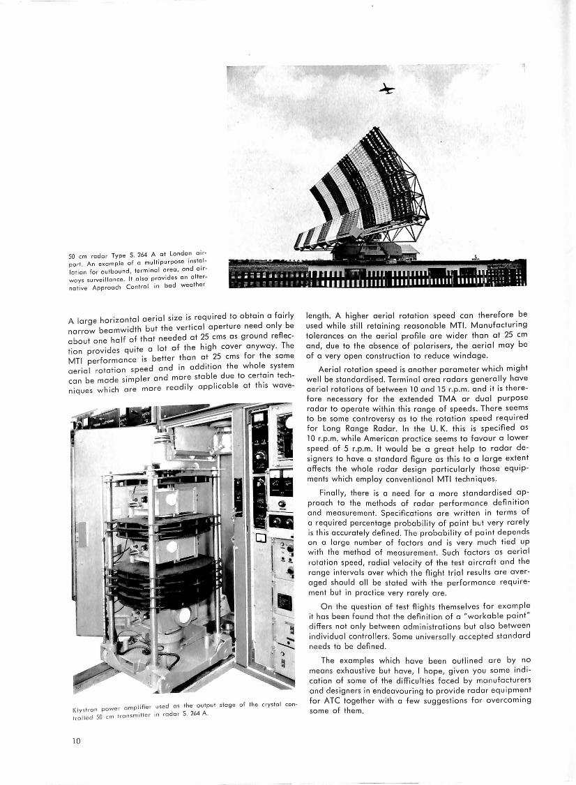
50 cm radar Type S. 264 A at London airport. An exa mpl e of a multipu rpose in stal
lation for outbound , terminal area , and airways surve i llance . It also provides an alter
nat ive Approach Control in bad weather
A large horizontal aerial size is required to obtain a fairly narrow beamwidth but the vertical aperture need only be about one half of that needed at 25 ems as ground reflec-. "d qu "ite a lot of the high cover anyway. The t1on prov1 es
MT! performance is better than a_t . 25 ems for the same · I t · · speed and in add1t1on the whole system aeria ro anon .
b d ·mpler and more stable due to certain tech-can e ma e s1 . · h . h are more readily applicable at this wave-n1ques w 1c
Kly sl ran powe r a mpli fi er _used as th e autpul stage of th e c rys ta l con
trol led 50 cm tra nsmitter in ra da r S. 264 A .
10
leng1h. A higher aerial rotation speed can therefore be used while still retaining reasonable MTL Manufacturing tolerances on the aerial profile are wider than at 25 cm and, due to the absence of polarisers, the aerial may be of a very open construction to reduce windage.
Aerial rotation speed is another parameter which might well be standardised. Terminal area radars generally have aerial rotations of between l 0 and 15 r.p.m . and it is therefore necessary for the extended TMA or dual purpose radar to operate within this range of speeds. There seems to be some controversy as to the rotation speed requ ired for Long Range Radar. In the U. K. this is specified as 10 r.p .m. while American practice seems to favour a lower speed of 5 r.p .m. It would be a great help to radar designers to have a standard figure as this to a large extent affects the whole radar design particularly those equipments which employ conventional MT! techniques.
Finally, there is a need for a more standardised approach to the methods of radar performance definition and measurement. Specifications are written in terms of a required percentage probability of paint but very rarely is this accurately defined. The probability of paint depends on a large number of factors and is very much tied up with the method of measurement. Such factors as aerial rotation speed, radial velocity of the test aircraft and the range intervals over which the flight trial results are averaged should all be stated with the performance requirement but in practice very rarely are.
On the question of test flights themselves for example it has been found that the definition of a "workable paint" differs not only between administrations but also between individual controllers. Some universally accepted standard needs to be defined .
The examples which have been outlined are by no means exhaustive but have, I hope, given you some indication of some of the difficulties faced by manufacturers and designers in endeavouring to provide radar equipment for ATC together with a few suggestions for overcoming some of them.

Towards a common understanding of ATC Anthony Martienssen
Nearly all controllers are gadget-minded. One sees signs of this in every Centre - here a device for silencing strip-holders, there a telephone on an extension arm, somewhere else an improved form of signalling lamps. The gadgets range from simple things like ball-points with different colours to elaborate runway lighting monitors in the Tower. Most, if not all, of these things were thought of first by controllers themselves - which is not really surprising since such improvements and inventions nearly always arise out of direct experience of the job. However, this tradition of gadget-mindedness, if I may call it that, has had one big drawback: it has tended to make controllers narrow-minded. We get irritated by the noise made when rearranging strip-holders; we invent a way of damping the noise; few of us ever stop to think of the function of strips in the system as a whole. And this is also true of the bigger gadgets like radar and navigation aids and, yes, computers. We get irritated by not being able to get a position report at the moment we need it! We think of all sorts of ways of solving this problem, from radar to computer operated air/ground data links; but few of us ever stop to think of the function of position reports in the system as a whole.
Can industry do any better than the controllers? Industry has gone to considerable trouble to meet what they think to be the needs of air traffic control. They have hired controllers and pilots to help them, and some have devoted a large part of their engineering talent and development resources to producing both ground and airborne equipment for air traffic control. Manufacturers, however, like controllers, are also primarily gadgetminded, though for different reasons. Profits in industry are made much more easily, and more quickly, by marketing a single instrument in large quantities than by trying to make and sell a complex system consisting of a variety of instruments, none of which will have a long production run. Furthermore, a manufacturer usually enters the market for ATC equipment either because he already has a gadget (designed for another purpose) which he thinks can also be sold as an ATC instrument, or because some bright engineer on his staff has had a good idea which is close to the normal products of the firm and which seems to him to be a useful thing for ATC. In both cases, the usual result is a high-powered itinerant salesman running around with a wonderful instrument and looking for (or inventing) an ATC problem for that instrument to solve. There are exceptions, but mostly the system as a whole is once more forgotten or ignored.
So much for industry. What about administrations? Here, indeed, there is a difference. The nature of a staff job at headquarters forces one to take a broad view. One moment you are dealing with a complaint about noise, the next you are advising on the precise location of a new VOR beacon, and after that you may have to handle a near-miss report or an embarrassing question from the Minister about why was his aircraft (with a VIP on board) held for ten minutes on his last flight back from Washington. Administrations, however, suffer from
a number of different and often conflicting influences. They are, for example, very sensitive to the opinions of controllers, pilots and operators, the users of the system. (You may not believe this, but I assure you it is true.) In addition, politics, both national and international, the interests of local industries, defence, national economics, lhe overall policy of the goverment concerning air transport, also all play their part in guiding the work of your staffs at headquarters. But it is very rare indeed to find any of these so-called pressure groups exerting their influence on behalf of a system concept. Once again it is a gadget, or at best a group of gadgets, which catches their imagination and arouses their support, so that headquarters staffs, very often against their will, are forced into the gadget-minded stream. Above all, nearly every headquarters that I know is short of staff and so overloaded by day-to-day job of administration that they have no time to sit back and think.
As for myself, however, I am only being wise after the event. Satco also started just like any other ATC gadget. When I first got the idea, way back in 1954, I was a mi Iitary Approach Controller looking after naval and air force aircraft operating within civil controlled airspace. The thing that irritated me and started me off trying to find a better way of doing things was the delay in getting outbound and inbound clearances from my civil colleagues in the Centre. Those were still the comparatively early days of jets, and the delays were sometimes dangerous - a fact which was of personal as well as professional concern to me since in those days I also used to make the odd flight in a Vampire or Meteor myself.
There were a number of ways in which the problem could be solved. My military colleagues were all in favour of radar, but I knew from my own experience of controlling large numbers of aircraft by radar that the capacity of a radar controller was strictly limited. Radar was an excellent means for supplementing position reports; it ~ould be used effectively for navigational guidance during an approach or for tricky situations en route provided that not more than three or four aircraft were involved; used by itself, however, it was inadequate as a control method. We had to know the pilot's intentions - and the intentions, or clearance instructions, of all the other pilots in the sector - and radar could not give us this. As a first step, therefore, it seemed to me necessary to improve procedure control (in which I had become '.n~~ctrinated by serving one watch in three with the civilian controllers) and then later to marry the two forms of control into one system.
At that time there seemed to be three weaknesses 111
the procedure control method: pilot's estimates and _controllers estimates were unreliable, the method of writing and distributing strips was much too slow, coordination of clearances between sectors and Centres was poor. (If a controller had solved a problem in his ~wn sector, he did not seem to mind too much - or he did not have time to think - about the consequences in the next sector.) If something could be done to put these things right, I thought, we would be well on our way to solving the
11
main part of the problem. And so i·he concept of Satco was born. But it was still a gadget, or rather group of gadgets: a dead-reckoning calculator which would take into account all the known factors affecting the calculation of estimates and which could be easily and quickly kept up-to-date by corrections resulting from position reports (or radar), an automatic flight progress board which would display strips - and changes to those strips - much more quickly than before, a system of conflict computing and light signals which would warn a controller if his neighbour had given a clearance which might later cause a conflict in his own sector. Like everybody else, however, we did not at that time see the ATC system as a whole. The light did not shine until much later. 17 was sorting out the details that showed us the way.
When I die, you will find engraved on my heart: "Details! Damned details!" It is one thing to sketch an idea for a gadget in smooth, broad outlines; it is something quite different to describe to an engineer in c~ear unequivocal terms the detailed specifications ~f a piece of hardware. What, for instance, were the precise factors involved in the calculation of estimates? That seemed on easy question: aircraft performance data, wind speeds and directions, temperature and pressure. But - what about the aircraft performance? Do all pilots fly the same way? Do all aircraft of the same type behave the same way? How many types of aircraft are there? Is the met. information reliable? Oh, well - let's get some figures and find out. Easier said than done. Then, we were asked: you talk about making corrections as the result of position reports: fine, but what about corrections as i·he. result of clearance instructions? What different types of clearances can be given? What are the details? How ma.ny variations and combinations of variations are possible? (About 500 OOO - in case you want to know.) You wish to show the.flight levei of an aircraft: if the clearance was "at or above" a certain flight level, what do you want shown -1he caiculated flight level? the cleared flight level? the
cleared airways flight level? the last reporred fl:ght le.vel? ihe cruising flight level originally planned by the pil.ot? the top-of-climb/ start-of-descent flight level?. the cru1seclincb flight level at that fix? or what? You think the ans· wer is obvious. Then you start to think. In such-and-such a case, I would like to know this. In another c~se, I would like to know Jhat. in yet another case,! would like_ to know both this and that. (In Satco, we ended up with three different flight levels on every strip.) What about times? We all know about actuals and estimates, of course. Many
~ I "e ~1·aosed times. But what about these -o, US a SO U> " . .
d h d Over tl.me initial time of entering area, propose an - ' . I exp .ires time flow-control stop and go limes, c e0t·ance , . . · sei·vation times< The route of an 0trcraft is wrspace re · d" f
another headache: there are at least half-a-dozen 1_f e-
rent ways of describing it, and I ha~e seen one flight I hich contained examples of all six. There are many
Pan w ·1 " d h. t f th more of these "damned deta 1 s , an t 1s par o e ·r. t·ons for Satco can take anything up to 250 close-spec111ca I . ff
iy typed pages, according to _the complexity of the tra 1c in the area where it is to be installed.
To an engineer, it is a crazy nightmare of apparently irrelevant and illogical procedures which could and should be reduced to a few nice equations plus, perhaps, a little practita I application of information theory and the Monte Carlo method. However, it usually happens that, by the
12
time the engineer is finished with his mathematical models, the translation of his equations into terms which controllers and pilots can use ends up in something just as complicated as we had before. The simple truth is that ATC is very complex, and, although we can certainly simplify (or, at !east, consolidate) a number of ATC procedures and habits, we will always be left with the hard fact of a system where men and machine move in ever-changing patterns in space and time, and which is, above all, subject to human temperament, mechanical imperfection and the uncertainty of the weather.
It was the details, as I said earlier, that led us to the broad system approach to ATC. Details show more clearly than anything else the close relationship - and the nature of that relationship - between the different parts of ATC. Take, for instance, what we know in Europe as ihe "Boundary Estimate" message. (For the benefit of controllers outside Europe, this is the message which one Centre sends to another giving details of a flight which is airborne and on its way to the next Flight Information Region. It is nearly always sent direct by telephone from controller - or assistant controller - to controller.) Now, one of the things we try to do in Satco is to speed up the passing of information from one Centre to another. As I think you will all agree, one of the most annoying breakdowns in the present ATC system is to be called up by a pilot entering your sector before you have received any information about that flight. We thought that if we could arrange things so that the recording of the actual time of departure in the original Centre would automatically cause a message to be sent to the next Centre, we would get rid of most, if not all, cases of unexpected arrivals. The only question was: what information should such a message contain? Obviously, we thought, something like, perhaps identical to, the boundary estimate message. This message also had the advantage that, provided we could send it out in ordinary teleprinter code, it could be used directly by Centres which had no automatic equipment as well as by those that did. However,
as you will have understood by now, nothing is obvious in ATC; nothing is simple. To begin with, the input in the Centre of origin had to be as short as possible - just the identity and the ATC, we thought - otherwise it would take as long (perhaps longer, if we had to rely on a onefinger typist) to get the message through as in the old manual system. Right. Where, then, were the rest of the details of the message to come from? This was not too difficult for us because in Satco the type of aircraft, route, clearance, estimates, etc., are all stored and can be extracted automaticaiiy. Our troubles started when we tried to t·ake into account situation such as radar hand-overs before the boundary is reached, or in cases where alternative transfer points are used according to the density of traffic, or where take-off clearances are subject to clearances from the adjacent Centre, or where there was no boundary fix (such places exist), or where it was a direct flight off airways, and so on. Every detail of the confounded message had problem after problem, but it was a blessing in disguise because it forced us to appreciate the relationship between flight planning and control procedures, between control and communication procedures, between position reporting and navigation aids, and between navigation aids and airspace organisation. It made us stop and think as deeply as we could for the first time about the ATC system as a whole

The process of thinking took a long time, nearly four years, and even now I cannot be certain that we have the complete picture of ATC. I see the system first as a number of functions in the form of a loop, each function leading on to the next until we come back to the beginning and start again. These functions are carried out for every flight we control.
Next, there are what I call the air traffic services: the Met. service, navigational systems, communications ground/ground, communications air/ground, radar, etc. Now, if you add the functions and the aids together, you get the picture of a very big system divided into a number of subsystems.
Control, you see, is just one sub-system. We believe it is the most important sub-system, the centre round which everything else revolves, but controllers cannot work without the other sub-systems. Further, my concept of the sub-systems is that, not only should each subsystem be so designed so that it can work together with the other sub-systems, but also that certain sub-systems should fill in gaps in other sub-systems. For instance, radar should be able to fill in the gap in navigational aids, control should help ground/ground communications, Met. should help control and flight planning, and so on. If we keep this clearly in our minds, we should then be able to fit all the parts neatly together in a smoothly purring system, doing its work with optimum efficiency and the minimum effort.
During these last few paragraphs, you may have been misled by the words "system" and "sub-systems" into thinking that I was writing about machines, computers and other electronic devices. This was not my intention. A system can consist entirely of human beings, or it can be entirely mechanical, or it can be both human and mechanical. In every sub-system in ATC there are both human and mechanical (or electronic) elements. The way in which the different functions are carried out - and by this I mean not only the method but also the means, man or machine - is determined, in this concept of the system, primarily by the organisation in the area in which the system is to be used.
By organisation I mean the four principal decisions which any administration must take before it can begin to provide any type of air traffic service at all. These are:
a) What traffic is to have what degree of air traffic service under what conditions? E. g. Civil transport, full ATC, under all weather conditions. Or, all aircraft, advisory service, IMC only. There are a number of possibilities, and the administration will make its choice based on traffic densities, international obligations, means and money available, etc.
b) What organisation of the airspace is required? E. g. airways? areas? upper/lower predetermined routes? control zones? etc.
c) What control method should be used? Basically, there are two possibilities: clearing aircraft through fixed geographical points, or clearing aircraft through variable positions using constant time steps. (The second
may sound complex to you, but it is in fact what an Approach Controller does using radar: the sweep of the antenna gives him his constant time steps, and he clears the aircraft according to the variable positions he receives with each radar sweep. In the "Free-route" or "Area" Satco, we have developed the idea of constant time steps to the extent that we can now carry out full procedure control on this same basis.) The decision as to which method to use is, of course, directly linked with the decision concerning the organisation of the airspace.
d) What control organisation should be set up? This is the organisation of sector responsibilities, Approach and Tower responsibilities, coordination requirements, flight planning arrangements, and so on. The decision is again linked with the decision on all the other points.
Underlying all the decisions, however, there are two other factors. Firstly, there is what exists already. In most western countries, air traffic control has just "grown up" more or less haphazarardly, and there is a history of established procedures and methods (which is one of our biggest headaches and which cannot easily be overcome). Secondly, there is the consideration of what resources are available for carrying out the functions in the way required by the organisation decisions. You will understand, therefore, that when we start building up - or modernising - the sub-systems, there is a constant interplay between organisation, tradition and techniques, and the choice of man or machine is by no means simple. In the Satco philosophy, we try to advise on each case according to its merits. We have our own rough rules for our own guidance, but it would take another article almost as long as this one to set those rules out and explain how we arrived at them. There are also so many other things that there is not space for discussion in one article - the question of reliability, for instance, how far should we go? or questions concerning the best forms of displays, and a whole host of questions concerning how to use computers _ but perhaps your Editor will give me an opportunity at some later date to discuss these matters with you. (With pleasure, Ed.).
In this article, I have tried only to give you the background and theory behind our work, and I can but hope that it may be of some use to you in achieving a common level of understanding of this most fascinating of professions - air traffic control.
Tirey K. Vickers honored by ATCA
A Special Award of the Traffic Control Association was
presented to Tirey K. Vickers on October 3rd, 1962, for
his "outstanding and imaginative contributions to the
science of air traffic control". The award was made at
the Seventh National Meeting of the Air Traffic Control
Association in Las Vegas, Nevada, October 1-3, 1962.
13

Man as Data-Processing Link in the Air Traffic Control Service
H. J. Zetzmann
Summary
Considering the flow of information in traffic control and prevention of collisions in aviation, the human o~erator is acting as a data-processing and data-~valuating link in the ground-based air traffic control service. By the constant increase of air traffic in volume and speed, the control problem is becoming critical now and then and the human being in its operational function is fac~d by increasing difficulties. In this respect the ad~ptat1on 15
constituting a decisive part in the man/machine s~stem. These anthropo-technical correlations (in the meaning of "human engineering") are shown and the psychical. ph~siological stress is dealt with, to which the human ~e1ng is exposed by the type of control actions, especially at the radar scope. To eliminate the "stress" and to tran~form the usual lack of time into sufficient time reserves is not only an aim of automation of air traffic control technique but a!so that of anthropo-technical adaptation of man and machine within the ATC servo-system.
Contents
Control of traffic flow and prevention of collisions
Remote information about the traffic situation
Display of the traffic situation
The requirements of control work and its
psycho-physical burden
The evaluation work at the control strip board The special psycho-physical problems of
radar scope evaluation
The lack of time as "stress" in air traffic control
Conclusion
Literature
Control of traffic flow and prevention of collisions
All types of traffic transporting men and goods on predetermined routes _ might it be on water, ground or in the air _ make it necessary at a certain traffic density to introduce an efficient surveillance system from the outside sphere, creating an expeditious and tin:ie-saving flow of traffic, at the same time being responsible th~t each · ' t ff'c element ;, never endangered to collide du-s1ng1e ra 1 , .. ·- . .
ring parallel, opposite or crossing flow of traffic at mi-
nimum possible separation.
The problem of collision prevention, namely: the sepa
ration is, by its nature, contradictin~ the des'.re for :los~r stacking as required by traffic continuously increasing 1n
speed or density.
In practice this generally valid. basic fact of traffic control is applying different techniques of data collecting data-transmitting and data-processing depending on the' type of transport and its characteristics. The control installations on the waterways, at canals or harbour outlets for instance, are working different from the surveillance and control installations of the railbound traffic of a great railroad center and both are - besides a cer-
14
lain similarity - different from the installations of the air traffic control service.
Remote information about the traffic situation
All installations of the different traffic disciplines are operated and will have to be operated by human beings, which we will generally call traffic controllers, since a completely automatic traffic flow will be a wishdream. As visual surveillance of the traffic elements is only possible to a very small fraction, the picture of the traffic situation has to be formed by a number of remote informations about position, process of manoeuvres and additional characteristics of the traffic elements. These data are forwarded to the surveillance and control position by the known means of remote action technique as there are: wire- or wireless communication, or both. The incoming information is mostly varying in its type. It might be regulated or non-regulated, pertaining to the single traffic elements as wel I as to the relation of traffic elements to each other, i. e.
by requesting individual items of information
information coming in automatically at certain periodic or non-periodic time intervals
by permanent offer of continuous data as given e. g. by plan position radar sets in maritime and air navigation.
Aside from its contents, information in itself is differing by volume and type, whereby the !otter one is existing in its ac~ustic form (speech), the written display alpha-numerically in open text or coded, and the optical form with a
more or .less schematic representation as light panels (~resentation of trackplan in the railway technique of s:gnalbox) or ~adar display, all these forms appearing sing.ly or combined. This incoming flow of different inforn:iot10.n has to be "composed" into a picture of the overall situation and to be evo-luated with regard to the control function.
Display of the traffic situation
The display of the traffic situation differs with the types of traffic. At slow traffic flow as for instance in the N?rd-Ostsee-Kanal (Kiel-Canal) the drawing of a route-lime-diagram by hand is sufficient in order to have a clear and precise traffic picture on hand and to be able to execute separation and prevention of col I is ions. It was done the same way in the air traffic services some 30 years ago.
It has always been the goal of the inventors to reach a true scaled-down reproduction of the actual traffic situation. The relatively best solution is the modern presentation of trackplan within the technique of signalbox of the railroad, which has a number of advantages as -without going into details - clear two-dimensionality, fixed roads, block formation, possibilities of collision only on pre-known crossing points etc. thus alleviating the
"controllers action" right from the beginning. Due to the high speed of the traffic means in aviation and their very ticklish separation problem, extremely high standards should be set with regard to survey and quick readability of the situation display. In foct, the present means do not at all represent a true scaled-down model let olone a three-dimensional display of the situation in the air. Furthermore such a display cannot be of great value due to the nature of the evaluation work and the decisions resulting from it. All real movements within a model display are so small and in practice remain stationary* for the evaluator, so that always much additional information is required for an easier evaluation. On account of this foct the model display is loosing its importance.
For the display and evaluation of the traffic situation all means of remote control technique have to be such, that the human evaluation work during the control action is as clear, simple and precise as it ever could be.
The comparative introduction is intended to indicate certain analogies between the different types of traffic, but also to make understandable, that the function of the air traffic controller is a field of operation, where the capacity of the traffic means depends directly and at certain times to a remarkably high degree upon the efficiency of the human link within the data-processing function. It may lead to a limitation of the traffic flow -and regrettably it often does at present - simply due to the foct that the servo-system of the air traffic service with the men working in it becomes a bottleneck.
The requirements of control work and its psycho-physical burden
In this study it is not intended to discuss the technical installations of the present air traffic services system and the viewpoints for its possible further development and automation in detail. This has been done several times on other occasions, for instance [l, 2]. The discussion of the problem is intended to be limited strict-ly to the human part only with the meaning of the adaptation of man/
Radio navigational machine, which has become a fixed aids
standard in the U.S. known as "human engineering". In Germany the expres-sion "Anthropotechnik" should be ap-plied, which has the advantage of per-mitting the use of the adjective form.
The naive or single system, that has been lined up to the machine and where the human being has to adapt himself ("fitting the man to the job").
An enlargement of this group is the system, where the human being and his capacity are limiting the total capacity at certain requirements. In such a case, the machine has to be fitted to the human being in order to reach better results ("man-centered system = fitting the job to the man").
The complex system [8], where the man and the machine have to be considered as own parts of the system; they are "system-centered". To reach the peak efficiency man and machine both have to be fitted to the problem ("fitting man and job to the system").
Air traffic control is a matter, which belongs to the second group according to its present stage of development, but will pass over into the third group during further outomation in dota handling.
Therefore it is the problem of air services technique, to accelerate the process of
data transfer
data handling and
display
by improvements and automation of the technical means to such a degree, that the requirements of the continou_sly
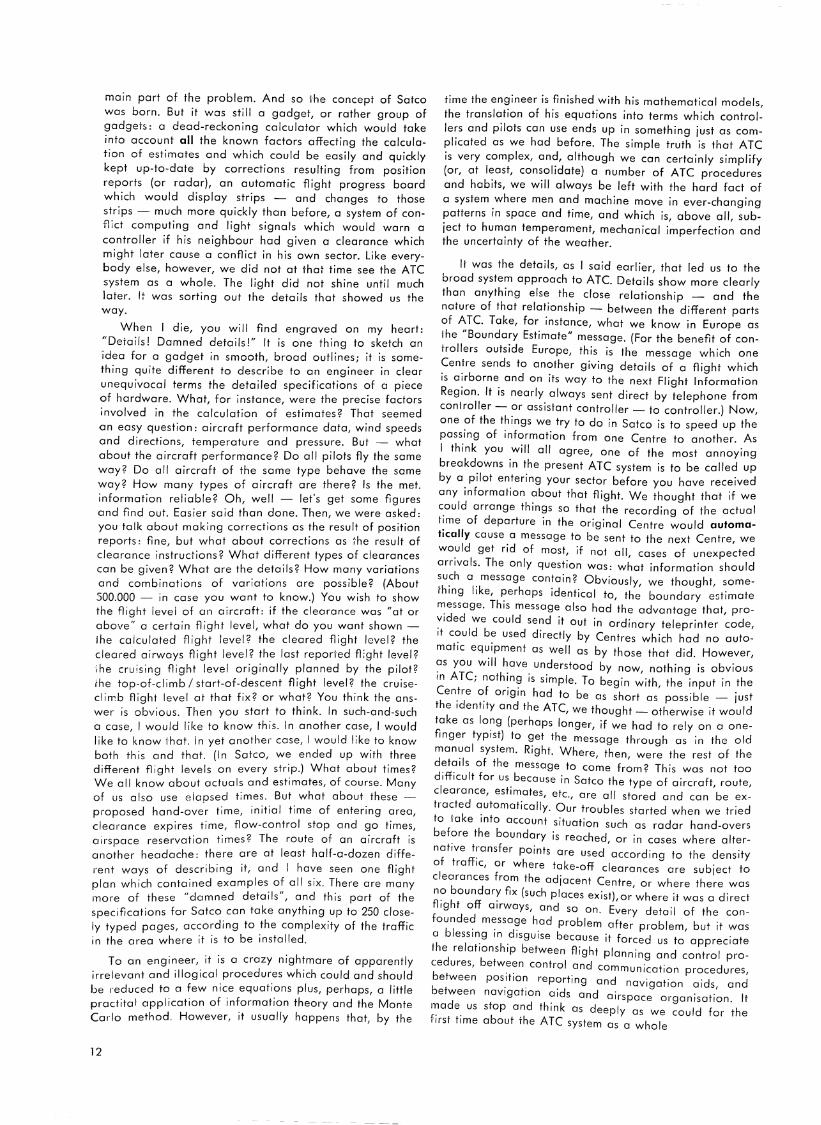
growing control velocity are met. Thereby man _b~ing switched into the servo-system is able to execute a l1m1ted number of control functions simultaneously only (in air traffic control approximately 5-6), picture 2, and due to the speed of his reactions, which cannot be increased as desired he necessarily more and more becomes the weakest
Pilot is flying according to instrument
0 in~nstructions.
~
radar set
The air traffic control work is shown schematically in picture l, it is a servosystem wherein a greater number of system loops have been connected parallel and where at deciding points a human being is positioned (here disregarding the pilot), who within the
instructions flow of informations
from aircraft
system loop intelligently processes the incoming data. In this system men and machine are linked to a chain of func-
tion.
Considering it from its psychological aspects such system, formed by men and machine, can be divided into
3 groups:
("sub-conscious") Fig. 1.
to aircraft
\ \ ~ 'I I
\ \ '/ 111 \II
Air Traffic Control
15
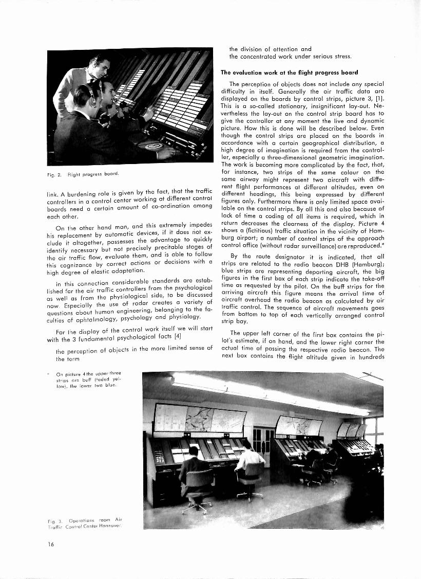
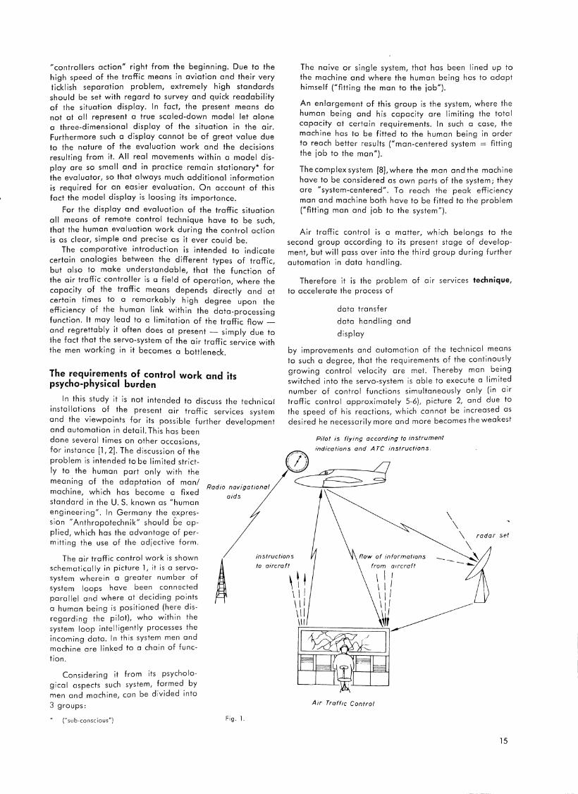
Fig . 2. Flight progress board .
I. k A b d · le 1·s given by the fact, that the traffic in . ur en1ng ro .
t II · trol center working at different control con ro ers 1n a con . . boards need a certain amount of co-ordination among
each other.
On the other hand man, and this extremely impedes
h · I t b automatic devices, if it does not ex-1s rep acemen y . elude it altogether, possesses the advan.tage to quickly ·d ·f but not precisely prec1table stages of 1 ent1 y necessary
h · ff" fl evaluate them and is able to follow t e air tra 1c ow, ' . . .
h. · b correct actions or dec1s1ons with a t 1s cognizance Y .
high degree of elastic adaptation.
I h. t "o n considerable standards are estab-n t. 1s connec 1 . lished for the air traffic controllers from the psychological
I ' f th"' physiological side, to be discussed as we 1 as rom ~ . c · 11 the use of radar creates a variety of
now. LSpec1a Y . . · h f · b t human engineering, belonging tot e a-questions a ou .
culties of ophtalmology, psychology ond physiology.
For the d is play of the control work itself we will start
with the 3 fundamental psychological facts (4]
the perception of obj ects in the more limited sense of
the term
On picture 4 the upper three strip s a re buff (faded yellow ), the lowe r two blue.
Fig . 3. Operations roo m A ir Traff ic Contro l Center Hannover .
16
the division of attention and the concentrated work under ser ious stress.
The evaluation work at the flight progress board
The perception of objects does not include any special difficulty in itself. Generally the air traffic data are displayed on the boards by control strips, picture 3, (l ] . This is a so-called stationary, insignificant lay-out. Nevertheless the lay-out on the control strip board has to give the controller at any moment the live and dynamic picture. How this is done will be described below. Even though the control strips are placed on the boards in accordance with a certain geographical distribution, a high degree of imagination is required from the controller, especially a three-dimensional geometric imagination. The work is becoming more complicated by the fact, that, for instance, two strips of the same colour on the same airway might represent two aircraft with different flight performances at different altitudes, even on different headings, this being expressed by different figures only. Furthermore there is only limited space avai lable on the control strips . By all this and also because of lack of time a coding of all items is required, which in return decreases the clearness of the display. Picture 4 shows a (fictitious) traffic situation in the vicinity of Hamburg airport; a number of control strips of the approach control office (without radar surveillance) are reproduced.*
By the route designator it is indicated, that all strips are related to the radio beacon DHB (Hamburg); blue strips are representing departing aircraft, the big f igures in the first box of each strip indicate the take-off time as requested by the pilot. On the buff strips for the arriving aircraft this figure means the arrival time of aircraft ove rhead the radio beacon as calculated by air traffic control. The sequence of aircraft movements goes from bottom to top of each vertically arranged control strip bay.
The upper left corner of the first box contains the pilot's estimate, if on hand, and the lower right corner the actual time of passing the respective radio beacon . The next box contains the flight altitude given in hundreds

DHB 90 EGLL
10 45 TWA 774
4 180
()7 OHB 80~ EDOF JO DHB
7031 LH082
/:: CR 210
fJ7 OHB -Bff I £KCH
7027 ~~ SAS 673
/:: 6 220
[7 DHB 75 EOBB
p 7025 FBALZ
/ vs 270
l7 DHB 60 EGLL
p 1020 LH602
/ CR 210
of feet, the number 90 therefore means 9000 feels. Numbers of altitudes that are crossed out indicate, that the aircraft has left this altitude upward or downward. A1·-1·ows show ascent or descent. The center of the big box in the middle of the control strip carries the radio call sign of the aircraft, the upper left corner the point of departure, the upper right corner the point of destination, the lower left the type of aircraft, the lower right the travelling speed (true air speed) in knots or nautical miles per hour. The following eight small boxes have different meanings in the air traffic control operation, depending whethe 1· this is a tower, approach or an area control unit, and will not be explained here now. The last big box at the right side contains the issued air traffic control clearances
or insti-uctions in coded form.
When this coded display is translated into open lan
guage it expiesses the following:
v [Z 25
S-!LS
v NC M>75 A
+1-> 6 5 WENTORF
25 /QC
V1 /OC
19
Fig. 4.
Aircraft SAS 613, coming from Cope:ihagen, was ;;upposed to overfly the radio beacon DHB at 10.27 hours
at en altitude of 8000 fet. A descent clearance for 5000 feet was issued initially, late1· on for 3000 feet and at 1025 ihe clearance fm a "Straight-in-ILS-approach" was given. But at 1028, one minute iaie1· than predete1·mined, SAS 613 was overflying the DHB radio beacon and staded the aerodrome apprnach. At the moment the ai1·uaft is about to land. The strips for LH 082 and TWA 714 have to be ,-ead acco1·dingly. LH 602 was to depmt fm London at 1020 hours. She received the desired flight altitude of 6000 feet and the insh"uction to "Climb on cou1·se (OC, last column). The depmture time was 1019 hours. Now the a i 1·crnft is
at 6000 feet and short of the radio beacon Weser The
strip fm F-BALZ according to the details of the last colu1nn reads: "Cleared to the airport of destination. Berlin via the Northern air corrido1·, maintain 7500 feet, but maintain 6500 feet to the Wentorf fan mmker, climb on cau1·se 1"
17
..---/ ' / DHB & '\
I '- LH082 //-ff'f J .& I I
STA ', _ _,y ~ SECTOR 'T
.\. rwA A "" ~" LH ,,.--602 /
/
SECTOR A 207~~0 FT
SEC TOR B -12Q!JfL FT 1700
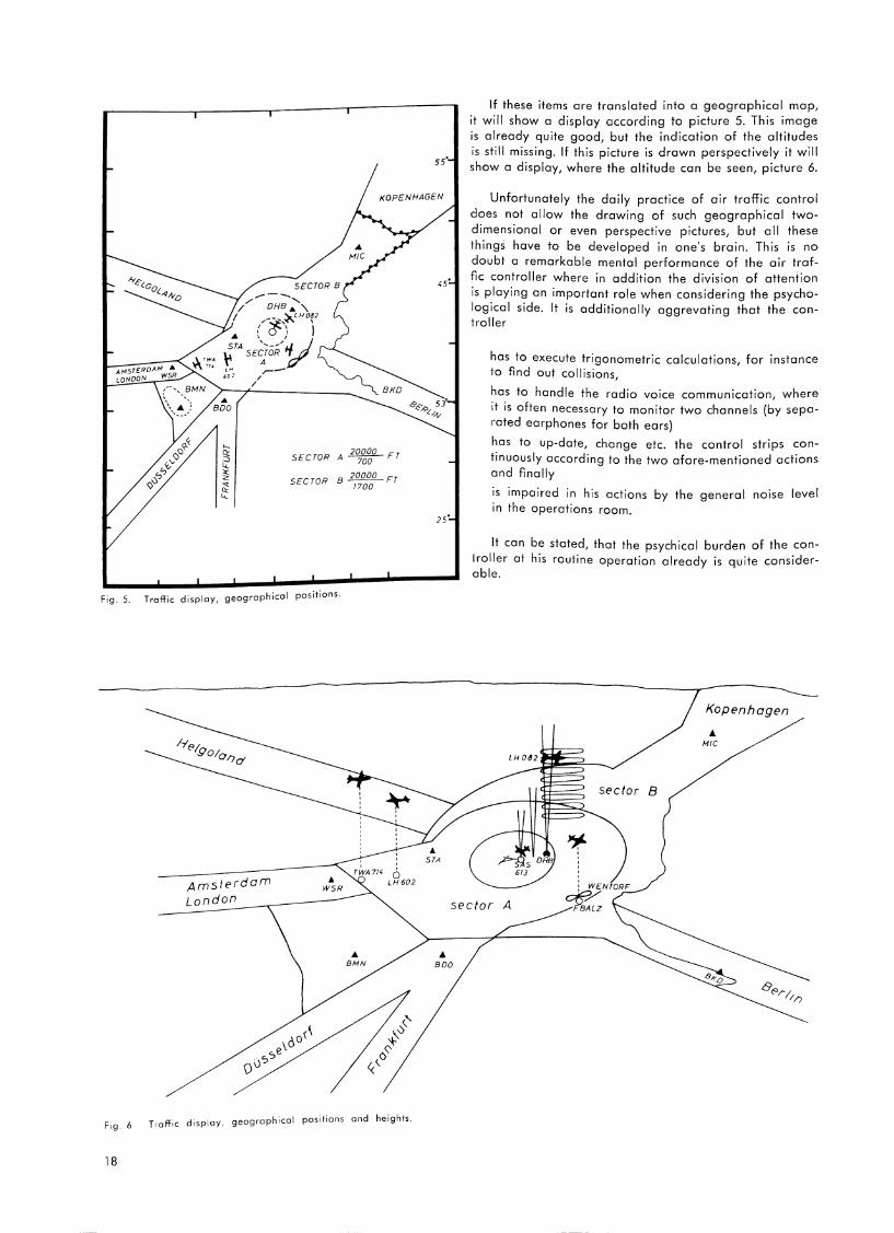
Fig. 5. Traffic display, geographical positions.
18
Amsterdam London
' TWA 714 0 LH602
.. BMN
Trnffic display, geographical positions and heights.
55'
STA
If these items are translated into a geographical map, it will show a display according to picture 5. This image is already quite good, but the indication of the altitudes is still missing. If this picture is drawn perspectively it will show o display, where the altitude can be seen, picture 6.
Unfortunately the daily practice of air traffic control does not allow the drawing of such geographical twodimensional or even perspective pictures, but all these things have to be developed in one's brain. This is no doubt o remarkable mental performance of the air traffic controller where in addition the division of attention is playing an important role when considering the psychological side. It is additionally aggrevating that the controller
has to execute trigonometric calculations, for instance 1o find out collisions,
has to handle the radio voice communication, where it is often necessary to monitor two channels (by separated earphones for both ears)
has to up-date, change etc. the control strips continuously according to the two afore-mentioned actions and finally
1s impaired in his actions by the general noise level 1n the operations room.
It can be stated, that the psychical burden of the coniroller at his routine operation already is quite considerable.
sector 8
Kopenhagen
... MIC
sector A
... BOO
1
\
The special psycho-physical problems of radar scope evaluation
Even the radar indication is, though derived from the dynamic process in the airspace, practically stationary because of the - if it is allowed to express it this way -high relation of transmission of the speeds from nature to the scale of display on the radar scope by its objective displacements. For this reason a long duration of afterglow of the screen is desirable in order to allow the recognition of the actually moving targets by their so- called afterglow trails.
A special onthropotechnical terrain not sufficiently covered yet is the evaluation work on the radar scope. The inefficeny from which the present radar technique is still suffering is not to be discussed now, but it is playing a decisive part for data-evaluation within the field of air traffic control technique [2]. The area covering PPI (plan position indicator) set naturally gives no information of altitudes, the comparative specification of the coding to the blips indicating the different targets has not been solved well yet, and the reliability of paint still needs im
provement.
In the following part only the operationally important problems of adaptation resulting from reading and evaluating the radar picture shall be discussed.
They have to be divided into
the visual problems of target detection the influence of the environmental light the problem of the oberserver's efficiency to the duration of observation.
1n relation
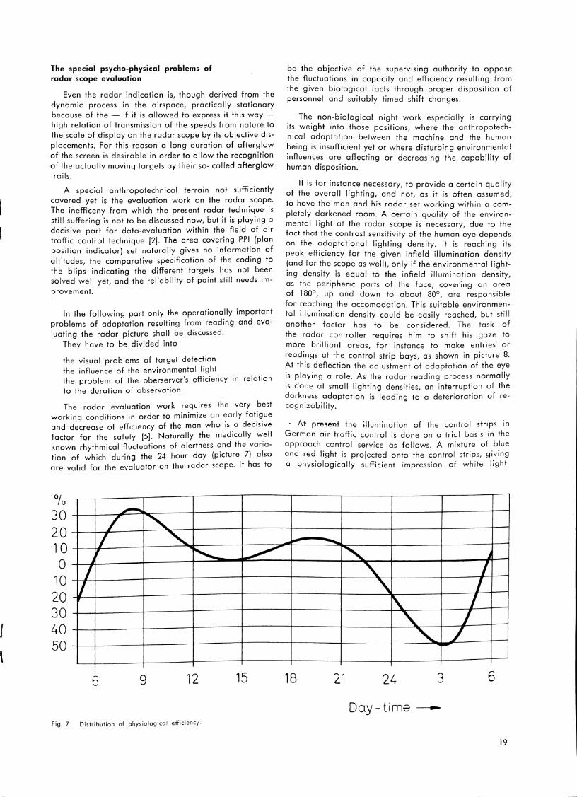
The radar evaluation work requires the very best working conditions in order to minimize an ~arly fat.i~ue and decrease of efficiency of the man who is a decisive factor for the safety [5]. Naturally the medically w_ell known rhythmical fluctuations of alertness and the variation of which during the 24 hour day (picture 7) also are valid for the evaluator on the radar scope. It has to
0/o JO 20 10 0
10 20 JO 40 50
~ z ~ L 'I ~
_j
f
6 9 12
Fig. 7. Distribution of physiologicai efficiency.
~
15
be the objective of the supervising authority to oppose the fluctuations in capacity and efficiency resulting from the given biological facts through proper disposition of personnel and suitably timed shift changes.
The non-biological night work especially is carrying its weight into those positions, where the anthropotechnical adaptation between the machine and the human being is insufficient yet or where disturbing environmental influences ore affecting or decreasing the capability of human disposition.
It is for instance necessary, to provide a certain quality of the overall lighting, and not, as it is often assumed, lo have the man and his radar set working within a completely darkened room. A certain quality of the environmental light at the radar scope is necessary, due to the fact that the contrast sensitivity of the human eye depends on the adaptational lighting density. It is reaching its peak efficiency for the given infield illumination density (and for the scope as well), only if the environmental lighting density is equal to the infield illumination density, as the peripheric parts of the face, covering on area of 180°, up and down to about 80°, are responsible for reaching the occomodotion. This suitable environmental illumination density could be easily reached, but still another factor hos to be considered. The task of the radar controller requires him to shift his gaze to more brilliant areas, for instance to make entries or readings at the control strip bays, as shown in picture 8. .At this deflection the adjustment of adaptation of the eye
is playing a role. As the radar reading process normally is done at small lighting densities, an interruption of the darkness adaptation is leading to a deterioration of recognizability.
· At present the il~umination of the control strips in German air traffic control is done on a trial basis in the approach control service as follows. A mixture of blue and red light is projected onto the control strips, giving a physiologically sufficient impression of white light.
..- --~ _j
~ l I
~ 1
t ' ,.......
18 21 24 3 6
Day-time~
19
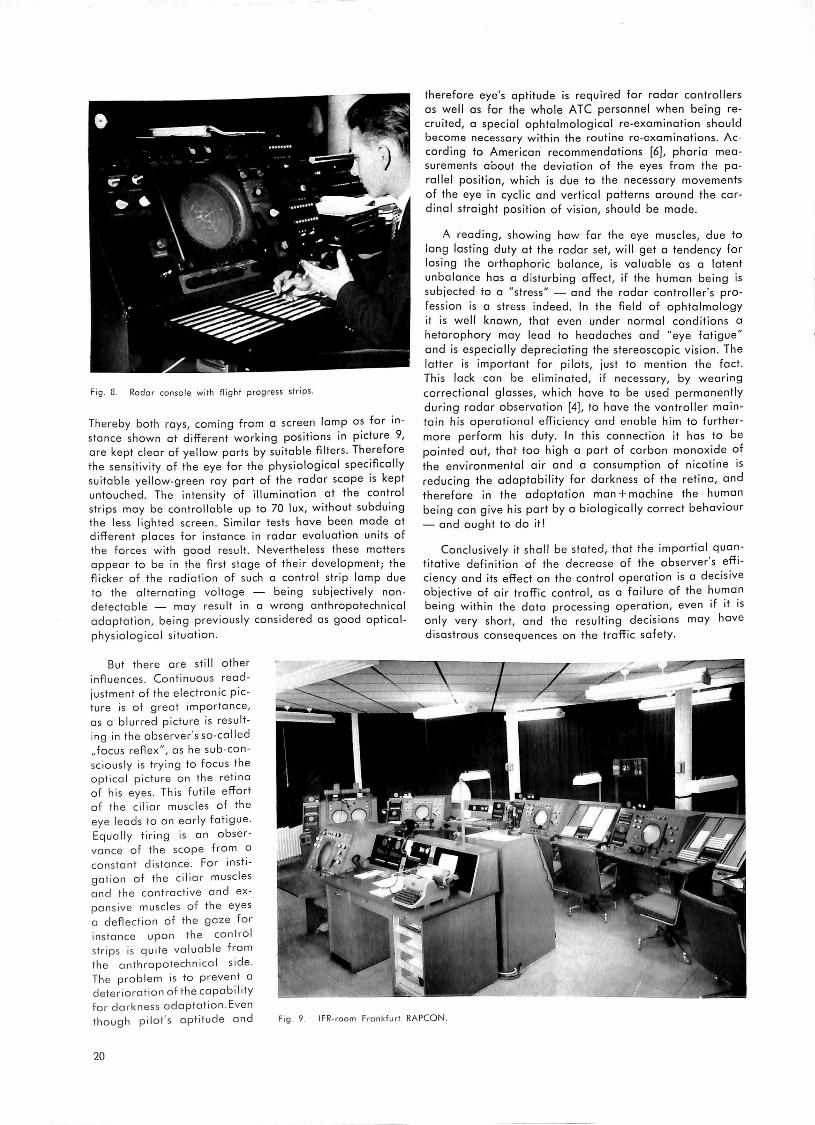
Fig . 8. Radar console with flight progress strips.
Thereby both rays, coming from a screen lamp as for instance shown at different working positions in picture 9, o re kept clear of yellow ports by suitable filters . Therefore the sensitivity of the eye for the phys iological specifically sui table ye llow-green ray port of the radar scope is kept untouched. The inten sity of illumination at the control stri ps may be controllable up to 70 lux, without subduing the less lighted screen . Similar tests hove been mode at different places for instance in radar evaluation un its of the forces with good result. N everth eless these matters appear to be in the first stage of their development ; the flicker of the radiation of such a control strip lamp due to the al ternating vo ltage - being subjectively non detectoble - may result in a w rong onthropotechnicol adaptatio n, being previously considered as good opticol
physiolog ico l situa tion.
therefore eye's aptitude is required for radar controllers as well as for the whole ATC personnel when being recruited, a special ophtolmolog icol re-examination should become necessary within the routine re-examinations . According to American· recommendations [6], phorio measurements about the deviation of the eyes from the parallel position, which is due to the necessary movements of the eye in cycl ic and vertical patterns around the cardinal straight position of vision, should be mode.
A reading, showing how far the eye muscles, due to long lasting duty at the radar set, will get a tendency for losing the orthophoric balance, is valuable as a latent unbalance hos a d isturbing affect, if the human being is subjected to a "stress " - and the radar controller 's profession is a stress indeed. In the field of ophtolmology ii is well known, that even under normal conditions a hetorophory may lead to headaches and "eye fatigue " and is especially depreciating the stereoscopic vision . The latter is important for pilots, just to mention the fact . This lock con be eliminated, if necessary, by wearing correctional glosses, which hove to be used permanently during radar observat ion [4], to hove the vontroller maintain h is operational eff iciency and enable him to furthermore perform his duty. In this connection it hos to be pointed out, that too high a port of carbon monoxide of the environmental air and a consumption of nicotine is reducing the adaptability for darkness of the retina, and therefore in th e adaptation man + machine the human being con give his port by a biologically correct behaviour
- and ought to do it!
Conclusive ly it shall be stated, that the impartial quantitative definition of the decrease of the observer' s efficiency and its effect on the control operation is a decisive obj ective of air traffic control , a s a failure of the human being within th e data processing operation, even if it is only very short, and the resu lt ing decisions may hove disastrous consequences on the traffic safety .
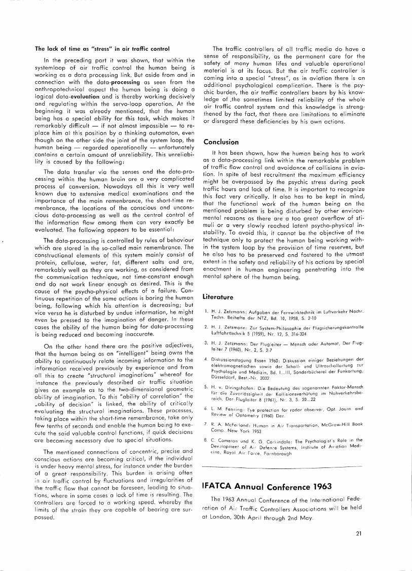
But there ore still other influences. Continuous read justment of the e lectronic picture is of great importance, as a blurred picture is res ulting in the observer 's so-co iled ,,focus reflex", as he sub-consc io usly is trying to focus the optica l picture o n th e retina of his eyes. Thi s f util e effort of the ciliar muscles of the eye leads to an ear ly fatig ue. Equa ll y tiring is an observance of the scope from o constant distance. For instigation of the ciliar musc les and th e controct ive and expansive musc les of the eyes a deflection of the gaze for instance upon the control strips is q uite va lu able from the anthropotechnical side. Th e problem is to prevent a deterioration of the capabi I ity for darkness adaptat ion . Even though pilot 's aptitude and Fig . 9. IF R-raam Frankfurt RAPCON .
20
The lack of time as "stress" in air traffic control
In the preceding part it was shown, that within the systemloop of air traffic control the human being is working as a data processing link. But aside from and in connection with the data-processing as seen from the anthropotechnical aspect the human being is doing a logical data-evaluation and is thereby working decisively and regulating within the servo-loop operation. At the beginning it was already mentioned, that the human being has a special ability for this task, which makes it remarkably difficult - if not almost impossible - to replace him al· this position by a thinking automaton, even though on the other side the joint of the system loop, the human being - regarded operationally - unfortunately conlains a certain amount of unreliability. This unreliability is caused by the following:
The data transfer via the senses and the data-processing within the human brain are a very complicated process of conversion. Nowadays all this is very well known due to extensive medical examinations and the importance of the main remenbrance, the short-time remenbrance, the locations of the conscious and unconscious data-processing as well as the central control of the information flow among them can very exactly be evaluated. The following appears to be essential:
The data-processing is controlled by rules of behaviour which are stored in the so-called main remembrance. The constructional elements of this system mainly consist of protein, cellulose, water, fat, different salts and are, remarkably well as they are working, as considered from the communication technique, not time-constant enough and do not work linear enough as desired. This is the cause of the psycho-physical effects of a failure. Continuous repetition of the same actions is boring the human being, following which his attention is decreasing; but vice versa he is disturbed by undue information, he might even be pressed to the imagination of danger. In these cases the ability of the human being for data-processing is being reduced and becoming inaccurate.
On the other hand there are the positive adjectives, that the human being as an "intelligent" being owns the ability to continuously relate incoming information to the information received previously by experience and from all this to create "structural imaginations" whereof for instance the previously described air traffic situation gives an example as to the two-dimensional geometric ability of imagination. To this "ability of correlation" the ,,ability of decision" is linked, the ability of critica!ly evaluating the structural imaginations. These processes, taking place within the short-time remembrance, take only few tenths of seconds and enable the human being to execute the said valuable control functions, if quick decisions are becoming necessary due to special situations.
The mentioned connections of concentric, precise and conscious actions are becoming critical, if the individual is under heavy mental stress, for instance under the burden of a great responsibility. This burden is arising often in air traffic control by fluctuations and irregularities of the traffic flow that cannot be foreseen, leading to situations, where in some cases a lack of time is resulting. The controllers are forced to a working speed. whereby the limits of the strain they are capable of bearing are surpassed.
The traffic controllers of all traffic media do have a sense of responsibility, as the permanent care for the safety of many human lifes and valuable operational material is at its focus. But the air traffic controller is coming into a special "stress", as in aviation there is an additional psychological complication. There is the psychic burden, the air traffic controllers bears by his knowledge of .the sometimes limited reliability of the whole air traffic control system and this knowledge is strengthened by the fact, that there are limitations to eliminate or disregard these deficiencies by his own actions.
Conclusion
It has been shown, how the human being has to work as a data-processing link within the remarkable problem of traffic flow control and avoidance of collisions in avialion. In spite of best recruitment the maximum efficiency might be overpassed by the psychic stress during peak traffic hours and lack of time. It is important to recognize !his fact very critically. It also has to be kept in mind, that the functional work of the human being on the mentioned problem is being disturbed by other environmental reasons as there are a too great overflow of stimuli or a very slowly reached latent psycho-physical instability. To avoid this, it cannot be the objective of the technique only to protect the human being working within the system loop by the provision of time reserves, but he also has to be preserved and fostered to the utmost extent in the safety and reliability of his actions by special enactment in human engineering penetrating into the mental sphere of the human being.
Literature
l. H. J. Zetzmann: Aufgaben der Fernwirktechnik im Luftverkehr Nachr.
Techn. Beihefte der NTZ, Bd. 10, 1958, S. 2-10
2. H. J. Zetzmann: Zur System-Philosophie der Flugsicherungskontrolle
Luftfahrttechnik 5 (1959), Nr. 12, S. 316-324
3. H. J. Zetzmann: Der Flugleiter - Mensch oder Automat, Der Flugleiter 7 (1960), Nr. 2, S. 2-7
4. Diskussionstagung Essen 1960: Diskussion einiger Beziehungen der elektromognetischen sowie der Schall- und Ultraschallortung zur Psychologie und Medizin, Bd. 1 ... 111, Sonderbucherei der Funkortung, Dusseldorf, Best.-Nr. 2032
5. H. v. Diringshofen: D;e Bedeutung des sogenannten Faktor-Mensch !Ur die Zuverlossigkeit der Kollisionsverhutung im Nahverkehrsbe
reich, Der Flugleiter 8 (1961). Nr. 3, S. 20 ... 22
6. L. M. Fenning: Eye protection for radar observer, Opt. Journ. and Review of Optometry (1960) Dez.
7. R. A. McFarland: Human in Ai 1· Transportation, McGraw-Hill Book Comp. New York 1953
8. C. Cameron und K. G. Corkindale: The Psychologist's Role in the Devalopmen! of Ai1· Defence Systems, lnstiiute of Aviation Medi
cine, Royal Air force, Fo!"nborough
IFATCA Annual Conference 1963
The 1963 Annual Conference of the International Fede
ration of Air Traffic Controllers Associations wil I be held
at London, 30th April through 2nd May.
21

Radar Spacing Techniques for the Final Approach Path
Tirey K. Vickers*
Separation Versus Capacity
Although it is not as well known as it should be, there is an inexorable physical law which states that traffic flow in any lane or channel is directly proportional to the average speed, and inversely proportional to the average interval between vehicles. In ATC terms, this is expressed by the equation, N = VIS, where N is the acceptance rate in aircraft per hour, V is the average ground speed in knots, and S is the average separation in nautical miles. The equation implies that there are two possi~le ways of increasing the acceptance rate - either by increasing the ground speed, or by reducing the separation. Since it isn't good practice to require pilots to fly higher approach speeds, the only practical method of increasing the acceptance rate of the approach lane is to find some means of reducing the average separation interval as low as possible, without the existing separation standards.
N0.1 A/C I D ~ FINAL I B r--M APPROACH COURSE --+.------I-I--~
NO I ; S _____--J ~
S = M + 8 + o(~ -1)
S = Initial separation, in nautical miles.
M = Minimum separation, in nautical miles (normally 3). 8 = Buffer, in nautical miles (normally 15 ta 20% of D). y, = Ground speed al Na. 1 aircraft, in knots. y, = Ground speed of No. 2 aircraft, in knots.
Fig. 1. Approach Spacing Equation for successive landings.
To use the spacing chart, you need a good estimate of the approach speeds which will be used by the individual aircraft. (If in doubt, you might ask the pilots.) For example, suppose that the Number One aircraft will fly at 130 knots, with Number Two at 150 knots. Suppose also th~re is a 10-knot headwind on the final approach path. This reduces the ground speeds of the two aircraft to 120 and 140 knots, respectively. To use the chart, first find the ve_rtic_ol line_ which_ represents 120; then go straight up this line until you intersect the horizontal line which re~res~nts 140. Th: location of this intersection you need; 1n this case the intersection is approximately on the fivemile diagonal line. This indicates that, when the Number ~ne aircraft is passing the reference point (six miles .rom touchdown) the Number Two aircraft should be no less than five miles behind it.
How much is Enough?
The amount of separation actually required between two aircraft starting down the final approach path _must be enough to maintain three miles separation at all times, in spite of any difference between the ground speeds of the two aircraft. This value can be computed mathematically, using the equation shown in Figure 1; but you probably won't have time to do this on the job. Th~refore, we have computed it for you already, for a typical turn-on distance of six nautical miles; the separation data is presented in chart form in Figur~ 2.
C\I
0 z 0 L&J L&J
~ 120~~.J..,,il~~-7"-:__-t-~-f7o&-t---t~-r-.:::iJll 0 z :::> 0 a:: <.!>
90-1£,,--Jb-,_.JllC:,,,...,...+--=oii......i;....L.~=+---a~..J---1
90 !20 150 180 GROUND SPEED NO. I (KNOTS)
Fig. 2. Spacing chart to obtain 3 miles separation at touchdown.
22
Numbers show separ·ation required (in nautical miles) when No. 1 aircraft is passing reference point 6 miles from touchdown.
Enginee1·ing Leade,·. Haze!tine Corporation Technical Development Center
Another example: The approach speeds of the Number One and Number Two aircraft are 130 and 120 k ot
. n ~
respectively; the headwind component is 20 knots, which '.11akes t~e ground speeds '.10 and 100 respectively. The intersection of the 110/100 lines lies halfway between the three-mile and four-mile separation lines, so the desired separation at the six-mile reference point is three and one-half miles.
You. will notice that within the shaded area at the lower right corner of the chart, the numbers call f
. or se-parations of less than three miles. The shaded area h d b . . covers
t e spee corn 1nations in which the Number Two · _ f• . . . a1rc1a , 1sh s1gn1fibcantly slohwer_than the_Number One aircraft, and t e num ers on t e diagonal lines simply show the _
. th . ·1 . h sepa rations at e s1x-m1 e point w ich would giv . e you at least three miles at touchdown. Obviously howe
' ver, you cannot use these reduced separations under present IFR standards. So under I FR conditions you must th
. . , use ree m_iles separation for all speed combinations which foll w1th1n the shaded area on the chart: This naturally will rnsult in a separation of more than three miles at touchdown.
Because of variations in the actual ground speeds of the aircraft on the way down the final approach th ·t · · f 1· h I po ' 1 1s necessary to aim or s 1g t.y more than three miles separation at touchdown, in order to ov01"d 0 · I
ccas1ona violations of the three-miles rule. For this reason, the

spacing chart shown in Figure 2 has an extra mile of separation built in as a buffer, or safety factor. This will keep your aircraft on the safe side of the three-mile minimum, even though the actual ground speeds of both aircraft may be off as much as 8% from the expected values.
Spacing Reference Lines
When you are trying to get exactly four and one-half miles spacing between a certain pair of aircraft, it would be very nice to have some sort of reference on the scope face to show you what four and one, half miles looks like. On the other hand, you don't want your radar scope to be cluttered up with a maze of confusing reference lines.
A satisfactory compromise is shown in Figure 3; this is a simple spacing reference which is made up to three concentric arcs, scaled at distances of 3, 6, and 9 nautical miles, respectively, from the minimum turn-on point on the final approach course. You can interpolate between the lines to get a close check on the distance between radar targets. For best results, the arcs should be incorporated into the video map or the radar overlay. However, you can draw them on the scope face with a grease pencil.
][
Fig. 3. Spacing Reference lines.
RUNWAY THRESHOLD
MINIMUM TURN-ON POINT
REFERENCE LINES /l
30 0
The Gain Concept
Two of the most important couses of poor spacing accurary are: (a) errors in the time starting the final turn toward the approach gate, and (b) variations in the turning rates of the aircraft. One way to approach this problem is to look for procedures which are relatively insensitive to these two sources of error.
An old adage in control-system design gives us a clue. It states that high-gain elements in a control loop characteristically produce high errors, or low accuracy; while low-gain elements produce low errors, or high accuracy. Don't let these engineering terms scare you. In an aircraft spacing system, what we "gain" is separation from the aircraft ahead; or delay in the arrival time, if you choose to look at it that way. In this applicotion, the terms highgain or low-gain refer to the rate at which we con pick up additional separation or delay.
As shown in Figure 4, an aircraft on an opposite heading from the approach gate is flying a path with a gain of approximately 2; in that for every second it stays on this path, it will delay its arrival time by 2 seconds. Thus, any error in the time of starting the turn will be magnified by 2. Such errors can result from controller misjudgement, communications lag, or pilot reaction time. For example,
APPROACH GATE (MINIMUM TURN-ON POINT)
w (/)
0::: ::i 0 u :i:: u <t 0 0::: a.. a.. <(
Fig. 4. The Gain Concept.
APPROXIMATE GAIN WHILE ON
HEADING SHOWN
o.o
o.5
1.0
23
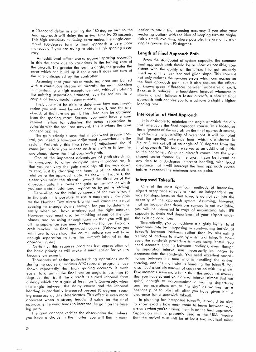
a 10-second delay in starting the 180-degree turn to the final approach will delay the arrival time by 20 seconds. This high sensitivity to timing error makes the single-command 180-degree turn to fina I approach a very poor maneuver, if you are trying to obtain high spacing accuracy.
An additional effect works against spacing accuracy in this the error due to variations in the turning rate of the aircraft. The greater the turning angle, the greater the error which can build up if the aircraft does not turn at
the rate anticipated by the controller.
Assuming that your radar vectoring area can be fed with a continuous stream of aircraft, the main problem in maintaining a high acceptance rate, without violating the existing separation standard, can be reduced to a
couple of fundamental requirements:
First, you must be able to determine how much separation you wi!I need between each aircraft, and the one ahead, at the turn-on point. This data can be obtained from the spacing chart. Second, you must have ~ convenient method for adjusting the actual separation '.0
coincide with the required amount. This is where the gain
concept applies. The gain principle says that if you want precise: con
trol, you need a low-gain adjustment somewhere in the system. Preferably this fine (Vernier) adjustment should come just before you release each aircraft to follow the
one ahead, down the final approach path. . One of the important advantages of path-stretchin~,
as compared to other delay-adjustment procedures, is that you can vary the gain smoothly, all the W?Y do"".n to zero, just by changing the heading of the aircraft in
relation to the approach gate. As shown in Figure 4, the closer you point the aircraft toward the direction of t_he approach gate, the lower the gain, or the rate at w~1ch you can obtain additional separation by path-stretching.
Depending on the relative speeds of the two aircra_ft in the pair, it is possible to use a moderately low gain on the Number Two aircraft, which will cause the actual spacing to change slowly enough for you to determine easily when you have attained just the right amou?t. However, you must also be thinking ahead of the a1rplanes, and be using enough gain so that you will get all the separation you need before the Number Two aircraft reaches the final approach course. (Otherwise you will have to overshoot the course before you will have enough separation to turn this aircraft inbound to the
approach gate.) Certainly, this requires practice; but appreciation of
the basic principles will make it much easier for you to
become an expert. Thousands of radar path-stretching operations made
during the course of various ATC research programs have shown repeatedly that high spacing accuracy is much easier to attain if the final turn-on angle is less than 90 degrees; that is, if the aircraft is turned inbound from a delay which has a gain of less than 1. Conversely, when the angle between the delay course and the inbound heading is gradually increased beyond 90 degrees, spacing accuracy quickly deteriorates. This effect is even more apparent when a strong headwind exists on the final approach; the wind tends to increase the gain on the base
leg path. The gain concept verifies the observation that, where
you have a choice in the matter, you will find it much
24
easier to attain high spacing accuracy if you plan your vectoring pattern with the idea of keeping turn-on angles fairly small, avoiding, where possible, the use of turn-on angles greater than 90 degrees.
Length of Final Approach Path
From the standpoint of system capacity, the common final approach path should be as short as possible, con~-istent with the ability of the aircraft to get properly lined up on the localizer and glide slope. This concept not only reduces the spacing errors which can accrue on the final approach path, but it also reduces the effects of known speed differences between successive aircraft. Because it reduces the touchdown interval whenever a slower aircraft follows a faster aircraft, a shorter final approach path enables you to a achieve a slightly higher landing rate.
Interception of Final Approach
It is desirable to minimize the angle at which the aircraft intercepts the final approach course. This facilitates the alignment of the aircraft on the final approach course by reducing the possibility of overshoot. It will be noted that the spacing reference lines, which are shown in Figure 3, are cut off at an angle of 30 degrees from the final approach. This feature serves as an additional guide to the controller. When an aircraft comes into the pieshaped sector formed by the arcs, it can be turned at any time to a 30-degree intercept heading, with good assurance that it will intercept the final approach course before it reaches the minimum turn-on point.
Interposed Takeoffs
. One of the most significant methods of increasing arrport acceptance rates is to install an independent runway f?r departures, so that takeoffs do not cut into the
capacity. of the approach system. Assuming, however, that an independent departure runway is not available
you V.:ill be _interested in ways of maximizing total IFR capac1_ty_ (arrivals and departures) of your airport under the exrsting conditions.
Theoretically, you can achieve a slightly higher total operations rate by interposing or sandwiching individual take?ffs betwe~n landings, rather than by alternating a string of landings followed by a string of takeoffs. However, the sandwich procedure is more comp I icat d y
d e . ou nee accur~te s_pacing between landings, even though the separation interval must necessarily be longer to acc?mmodate the sandwich. You need excellent coordinati~n between the man who is handling the arrival spacing, and the man who is handling the takeoff y
I d . . OU a so nee a certain amount of cooperation with the pilots. Few moments seem more futile than the sudden d. h h . . 1scovery
t ~t you ave spread your arrival interval almost (but not quite) enough '.o accommodate a waiting departure; and few operations are as "twitchy" 0 - ·t· f s wa1 1ng or a hesitant pilot to blast off after you have · h" clearance for a sandwich takeoff.
given 1m a
In planning for interposed takeoffs, it would be nice to know exactly how much room to leave b~t . , , . "° ween your amvars when you re turning them in on the fi I h . . . 1na approac . Separation m1nrma presently used in the USA · h h . require
t at t e arrival must still be at least two n t" I ·1 au 1ca m1 es
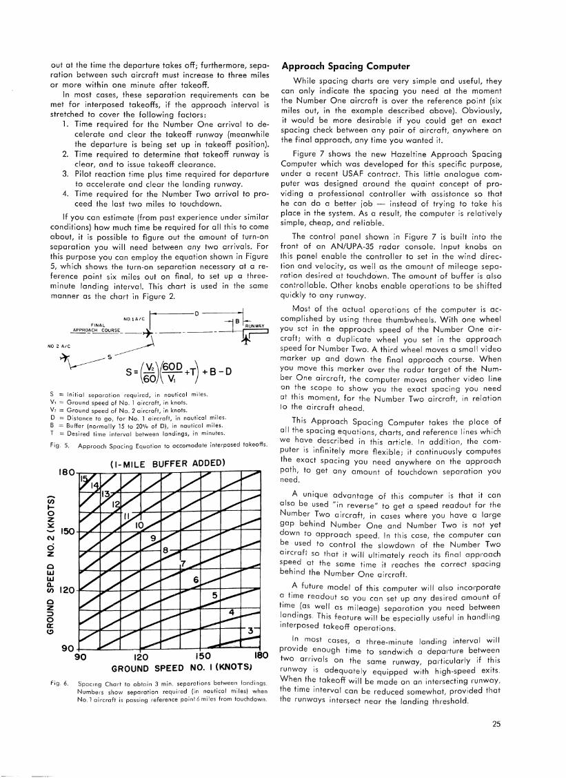
out at the time the departure takes off; furthermore, separation between such aircraft must increase to three miles or more within one minute after takeoff.
In most cases, these separation requirements can be met for interposed takeoffs, if the approach interval is stretched to cover the following factors:
1. Time required for the Number One arrival to decelerate and clear the takeoff runway (meanwhile the departure is being set up in takeoff position).
2. Time required to determine that takeoff runway is clear, and to issue takeoff clearance.
3. Pilot reaction time plus time required for departure to accelerate and clear the landing runway.
4. Time required for the Number Two arrival to proceed the last two miles to touchdown.
If you can estimate (from past experience under similar conditions) how much time be required for all this to come about, it is possible to figure out the amount of turn-on separation you will need between any two arrivals. For this purpose you can employ the equation shown in Figure 5, which shows the turn-on separation necessary at a reference point six miles out on final, to set up a threeminute landing interval. This chart is used in the same manner as the chart in Figure 2.
1 · D -~ NO.!A/C B FINAL RUNWAY APPRO~CH COURSE_--+- __ . __ ----~
NO 2 A/C ~ .It! ~ s
~ s=(:;)~6~0 +T)+s-o S = Initial separation required, in nautical miles. V, = Ground speed of No. l aircraft, in knots. y, = Ground speed of No. 2 aircraft, in knots. D :::::: Distance to go, for No. 1 aircraft, in nautical miles. B = Buffer (normally 15 to 20% of D), in nautical miles. T = Desired time interval between landings, in minutes.
Fig. 5. Approach Spacing Equation to accomodate interposed takeoffs.
(I-MILE BUFFER ADDED)
--Cl) I-0 z :z:::
150 N
d z 0 LLI LLI a..
120 (/)
0 z :::> 0 a:: (!)
90 90 120 150 180
GROUND SPEED NO. I (KNOTS)
fig. 6. Spacing Chart to obtain 3 min. separations between landings. Numbers show separation required (in nautical miles) when No. l aircraft is passing reference pain~ 6 miles from touchdown.
Approach Spacing Computer
While spacing charts are very simple and useful, they can only indicate the spacing you need at the moment the Number One aircraft is over the reference point (six miles out, in the example described above). Obviously, it would be more desirable if you could get an exact spacing check between any pair of aircraft, anywhere on the final approach, any time you wanted it.
Figure 7 shows the new Hazeltine Approach Spacing Computer which was developed for this specific purpose, under a recent USAF controct. This little analogue computer was designed around the quaint concept of providing a professional controller with assistance so that he can do a better job - instead of trying to take his place in the system. As a result, the computer is relatively simple, cheap, and reliable.
The control panel shown in Figure 7 is built into the front of an AN/UPA-35 radar console. Input knobs on this panel enable the controller to set in the wind direction and velocity, as well as the amount of mileage separation desired at touchda"wn. The amount of buffer is also conirollable. Other knobs enable operations to be shifted quickly to any runway.
Most of the actual operations of the computer is accomplished by using three thumbwheels. With one wheel you set in the approach speed of the Number One aircraft; with a duplicate wheel you set in the approach speed for Number Two. A third wheel moves a small video marker up and down the final approach course. When you move this marker over the radar target of the Number One aircraft, the computer moves another video line on the scope to show you the exact spacing you need at this moment, for the Number Two aircraft, in relation lo the aircraft ahead.
This Approach Spacing Computer takes the place of all the spacing equations, charts, and reference lines which we have described in this article. In addition, the computer is infinitely more flexible; it continuously computes the exact spacing you need anywhere on the approach path, to get any amount of touchdown separation you need.
A unique advantage of this computer is that it can also be used "in reverse" to get a speed readout for the Number Two aircraft, in cases where you have a large gap behind Number One and Number Two is not yet down to approach speed. In this case, the computer can be used to control the slowdown of the Number Two aircrafi- so that it will ultimately reach its final approach speed at the same time it reaches the correct spacing behind the Number One aircraft.
_A future model of this computer will also inco1·porate ~ time readout so you can set up any desired amount of time. (as well as mileage) separation you need between !andrngs. This feature will be especially useful in handling interposed takeoff operations.
In most cases, a three-minute landing interval will provide enough time to sandwich a depmture between two rn-i-ivals on the same runway, padicularly if this runway is adequately equipped with high-speed exits. When the takeoff will be made on an intersecting rnnway, the time interval can be reduced somewhat, provided that the runways intersect near the landing threshold.
25
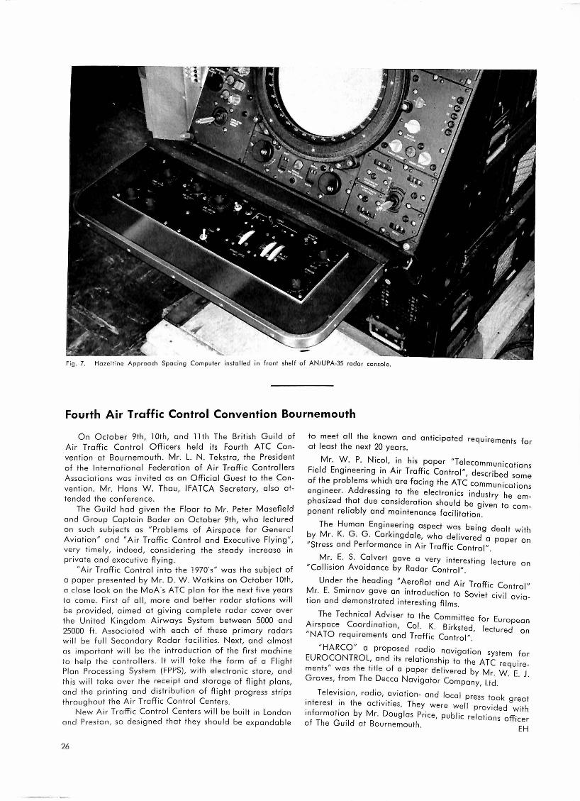
fig. 7. Hazeltine Approach Spacing Computer installed in front shelf of AN/UPA-35 radar console .
Fourth Air Traffic Control Convention Bournemouth
On October 9th, lOth, and 1 lth The British Guild of Air Traffic Control Officers held its Fourth ATC Convention ot Bournemouth . Mr. L. N . Tekstra, the President of the International Federation of Air Traffic Controllers Associations was invited as an Official Guest to the Convention. Mr. Hans W. Thau, IFATCA Secretary, also attended the conference.
The Guild had given the Floor to Mr. Peter Masefreld and Group Captain Bader on October 9th, who lectured on such subjects as "Problems of Airspace for General Aviation " and "Air Traffic Control and Executive Flying ", very timely, indeed, considering the steady increase in private and executive flying.
"Air Traffic Control into the 1970's" was the subject of a paper presented by Mr. D. W. Watkins on October 1 Oth, a close look on the MoA's ATC plan for the next five years to co me. First of all, more and better radar stations will be provided, aimed at giving complete radar cover over the United Kingdom Airways System between 5000 and 25000 ft. Associated with each of these primary radars wi ll be full Secondary Radar facilities. Next, and almost as important will be the introduction of the first machine to help the controllers . It will take the form of a Flight Plan Process ing System (FPPS), with electronic store, and this wi ll take over the receipt and storage of flight plans, and the printing and distribution of flight progress strips throughout the Air Traffic Control Centers.
New Air Traffi c Control Centers will be built in London and Pres ton , so designed that they should be expandable
26
to meet all the known and anticipated requirements for at least the next 20 years.
Mr. W. P. Nicol, in his paper "Telecommunications Field Engineering in Air Traffic Control", described some of the problems which are facing the ATC communications engineer. Addressing to the electronics industry he emphasized that due consideration should be given to component reliably and maintenance facilitation.
The Human Engineering aspect was being dealt with by Mr. K. G . G. Corkingdale, who delivered 0 paper on "Stress and Performance in Air Traffic Control".
Mr. E. S. Calvert gave a very interesting lecture on "Collision Avoidance by Radar Control" .
Under the heading "Aeroflot and Air Traffic Control" Mr. E. Smirnov gave an introduction to Soviet civil aviation and demonstrated interesting films.
. The Technical_ Adviser to the Committee for European Arrspace Coordrnatron, Col. K. Birksted, lectured on "NA TO requirements and Traffic Control".
"HARCO" a proposed radio navigation system for EURO,~ONTROL,. and its relationship to the ATC re quirements was the trtle of a paper delivered by Mr. W. E. J. Groves, from The Decca Navigator Company, Ltd.
Television, radio, aviation- and local press took reat interest in the activities. They were well provided g with information by Mr. Douglas Price, public relations officer of The Guild at Bournemouth. EH

A rapid scanning infra-red system for avoiding collisions in the air* C. M. Cade
A rapid scanning infra-red system for collision avoidance in the air is proposed which completes a 360 degrees search, from horizon to 30 degrees elevation, in a time of five seconds, with a pencil beam of 0.l degree included angle. Alternatively, a beam of 0.2 degree included angle may be employed and a 360 degrees search from horizon to 60 degrees elevation made in the same time.
Using existing detectors, the range in clear weather is calculated to be about 130 miles (210 kilometres). Apart from military applications, such a system has obvious potentialities as an anti-collision proximity warning.
Advantages of Infra-Red
1. Infra-red systems operating on passive reception are not limited in information-rate by echo-propagation time.
2. It is possible to obtain very high angular resolution with infra-red systems.
3. For military purposes, the passive infra-red system has the great advantage of being undetectable in use.
4. Compared with radars of equivalent function, infra-red systems are lighter, smaller, less complex and less expensive.
Disadvantages
There are basically three disadvantages to infra-red systems:
l. The ratio of the minimum detectable signal Pr min., for a radar set, to the minimum detectable signal Pt min., for a thermal receiver, is about 10-21 watt to l 0-12 watt, or in other words, the radar is l 09 times as sensitive as the infra-red receiver.
2. Infra-red radiation is attenuated far more severely than is the centimetric wavelength radiation used by a radar set.
3. Passive infra-red systems supply no range information.
The first of these disadvantages is partly offset by the greater gain of infra-red receivers produced by the im-
o.:ME T.\·.:.:· • .:.p4\~T Tc
APPROPR11/TE n/-'Jye; t!S>JN/'
~AtJAR Feet:> OR
!NFIVI~ [lt!TE'-TOR
AX/5 OF rl1 uH Sf'EEt>
~TllrlON
Fig. 1,n. •.
Courtesy "British Features".
proved wave-length/aperture ratio, and is further offset by the fact that in a passive system the radiation has to traverse the path once only, and back-scattering is less serious for this reason.
Over-riding Effect of Information-Rate and Resolution
If infra-red systems are inadequate when there is an all-weather operational requirement, it still must be borne in mind that, on the counts of resolution and of information-rate, conventional pulse-radar is frequently inadequate, even in perfectly clear weather.
In a passive system in which the target is the transmitter, range information is not available; and the plan position indicator cannot be used. However, both bearing and elevation of the target may be displayed on a cathode ray tube instead of bearing and range, by employing a hemispherical scan. Some idea of aspect may a!so be given by the hot "wake" behind the aircraft.
A system suitable for generating and displaying a hemispherical scan is illustrated in Figures 1, 1 A and l B. It wi!! be noted that the periphery of the C.R.T. screen represents the 360 degrees of the horizon, just as with a normal PPI, but the centre of the screen represents the
Fig. l.
P41V480LCID. tl/M£!V5/C'N:!> 4.:.ct:'.£NN6'
77> 0PJ:R4TICIV,ql... W.4Y£~111.:;.rH t
Fig. 1 B.
27
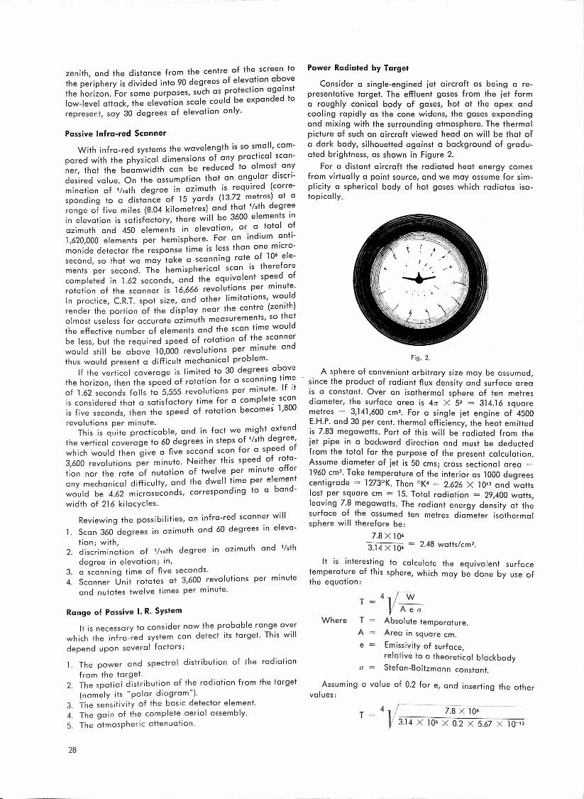
. . h t of the screen to zenith, and the distance from t e cen re . the periphery is divided into 90 degrees of elev~tion ab?ve
. h s protection against the horizon. For some purposes, sue 0 d d low-level attack the elevation scale could be expan e to
' . I represent, say 30 degrees of elevation on Y·
Passive Infra-red Scanner
With infra-red systems the wavelength is so s~all, corn-. . 1 d " · f any pract1cal scan-pared with the phys1ca 1mens1ons o
ner, that the beamwidth can be reduced to almost. an: t . th t an angular d1scr1-desired value. On the assump ion a .
mination of '/10th degree in azimuth is required (corre-. . f 15 d (13 72 metres} at a spending to a distance o yar s ·
. . k"I } d that 1/sth degree range of five miles (8.04 1 ometres an . in elevation is satisfactory, there will be 3600 elemen~s 1 ~ azimuth and 450 elements in elevation, or 0 . tote ~ 1,620,000 elements per hemisphere. For an indium ~ntimonide detector the response time is less than one micr
1o-
. ate of 1 o• e e-secon d so that we may take a scanning r ' h . h · I can is therefore ments per second. The em1sp erica s f
completed in 1.62 seconds, and the equivalent spe~d 0
. . 666 I fons per minute. rotation of the scanner 1s 16, revo u 1 . . Id In practice, C.R.T. spot size, and other limitations, wo~h}
. d. 1 the centre (zen1t render the portion of the 1sp ay near h . h rements so t at almost useless for accurate az1mut measu . ' Id
the effective number of elements and the scan time wou be less but the required speed of rotation of the scannedr
' · te an would still be above 10,000 revolutions per minu thus would present a difficult mechanical problem.
If the vertical coverage is limited to 30 degrees ab?ve the horizon then the speed of rotation for a scanning time
' . t If 1t of 1.62 seconds falls to 5,555 revolutions per minu e. is considered that a satisfactory time for a complet~ scan is five seconds, then the speed of rotation becomes l ,800
revolutions per minute. . d This is quite practicable, and in fact we might exten
. d · t of '/sth degree, the vertical coverage to 60 egrees 1n s eps which would then give a five second scan for a speed of
. N · h th" peed of rota-3 600 revolutions per minute. e1t er is s ' f · f t I per minute offer tion nor the rate o nutation o we ve
. . . 1 d th d II time per element any mechan1cal d1ff1cu ty, an e we would be 4.62 microseconds, corresponding to a band-
width of 216 kilocycles .
Reviewing the possibilities, an infra-red scanner will
1. Scan 360 degrees in azimuth and 60 degrees in eleva
tion ; with, 2. discrimination of 1/10th degree in azimuth and '/sth
degree in elevation; in, 3. a scanning time of five seconds. . 4. Scanner Unit rotates at 3,600 revolutions per minute
and nutates twelve times per minute.
Range of Passive I. R. System
It is necessary to consider now the probable range over which the infra-red system can detect its target. This will
depend upon severe I factors ;
1. The power and spectral distribution of the radiation
from the target. 2. The spatial distribution of the radiation from the target
(namely its " polar diagram "}. 3. The sensitivity of the basic detector element. 4. The gain of the complete aerial assembly.
5. The atmospheric attenuation .
28
Power Radiated by Target
Consider a single-engined jet aircraft as being a representative target. The effluent gases from the jet form a roughly conical body of gases, hot at the apex and cooling rapidly as the cone widens, the gases expanding and mixing with the surrounding atmosphere. The thermal picture of such an aircraft viewed head on will be that of a dark body, silhouetted against a background of graduated brightness, as shown in Figure 2.
For a distant aircraft the radiated heat energy comes from virtually a point source, and we may assume for simplicity a spherical body of hot gases which radiates isotopically.
Fig. 2.
A sphere of convenient arbitrary size may be assumed, since the product of radiant flux density and surface area is a constant. Over an isothermal sphere of ten metres diameter, the surface area is 4n X 5' = 314.16 square metres = 3,141,600 cm'. For a single jet engine of 4500 E.H.P. and 30 per cent. thermal efficiency, the heat emitted is 7.83 megawatts. Part of this will be radiated from the
jet pipe in a backward direction and must be deducted from the total for the purpose of the present calculation .
Assume diameter of jet is 50 ems; cross sectional area =
1960 cm'. Take temperature of the interior as 1000 degrees
centigrade = l 273°K. Then ° K• = 2.626 X 10" and watts lost per square cm = 15. Total radiation = 29,400 watts, leaving 7.8 megawatts. The radiant energy density at the
surface of the assumed ten metres diameter isotherma I sphere will therefore be:
7.8 x 10⁶
3.14 X lO• - 2.48 watts/cm'.
It is interesting to calculate the equivalent surface temperature of this sphere, which may be done by use of the equation:
T 4v w A ea
Where T Absolute temperature .
A Area in square cm .
e Emissivity of surface,
relative to a theoretical blackbody
a = Stefan-Boltzmann constant.
Assuming a value of 0.2 for e, and inserting the other values:
T - 4 I 7.8 x 10⁶ -- 13.14 x 10• x 0.2 x 5.67 x 10-12

= 4 i/2.19 X 1012 = 1216°K
This is equal to 943 degrees centigrade which seems a probable value.
Cl.l.(VE
I ll 11! IF If JZ[
'I'll 'EllI
l·O
.... 0·9
~ ~ 0·8
~ a 0·7
~ ~ O·~ ~
! O·S i.;
0·4
JV,'l•/~OW ~EGIONS IN ih',: IN~~AREI> (.4,r.c..r £J.#l.f ~ ~r..ro11111)
Wl.V#OW ,,.vrt.eNw?'J(L/ K,
0·72-0·'2 IS·!
O· 'z. - I· I 1'·5
I· I - /.4 11·1
1·4 - ,., 13.1 ,., -2·7 13·1
2·7 - 4·:3 12.s
*·3 -5., 21·2 5., - 14 -
0·01 0·1 10
PK.!Cl"rAal.I wATFA/ (••)
t, 106·3 106·3
96·3 Sl·O 7Z·.5 72·3 51.2
-
T;tANSH!SSIQN C~,..l'JCJE'NT !'LOTTE{> A~lllN.ST '"'"·
o,r l';f£Cll'Jrll61..I!: WllT&IC 1'0/C WAVELl!:N$TH3 ~RONI
O· !2 ro .S· !I MICRONS ' ( Al'Tlt/C ELDEIC .. S'f'Al<WCi .)
Fig. 3.
Detector Sensitivity
The characteristics of jet-engine effluents are such that a range of about 2.5 to 11 microns may be encountered, although a large part of the energy will be in the two bands, 2.5-3.2 ,u and 4.2-4.5 ,u, due to carbon dioxide and to water vapour respectively. Indium antimonide is quite suitable for use in this region (see Figure 4 A), although refrigerated lead telluride would also be of use (at 90 degrees Absolute, - 183 degrees Centigrade lead telluride shows 50 per cent. of its maximum response at about l micron and 4.9 microns). The response time of lead telluride, however, is far too long, whereas the response time of indium antimonide is almost ideal. For these cells the minimum detectable power is about 4 X 10·9 watts per cycle for a window area of three sq. mm.
The Gain of the Aerial
This is given by the ratio of the effective area of the collecting paraboloid to the area of the sensitive element. For an 18 inch (45.72 centimetre) paraboloid the surface area is 1640 cm2, and if the effective aperture is taken as 80 per cent., this gives 1312 cm2. The gain is therefore
0 2 4 6 >.. (.U)
Sl'ECT,('4L RE.3/'0NSE llVIJll/M ANT"IMONlt>E
(ffVLIJIKO ORPJO)
Fig. 4A.
1312X100
3 = 43,700.
8
Calculation of Maximum Range, neglecting Attenuation
The minimum detectable signal for the 3 mm2 indium antimonide cell is 4 X 10⁻⁹ watts per cycle = 1.33 X 10⁻¹
watts per cm2 per cycle, and for a bandwidth of one megacycle this becomes 1.33 x 1 o-· watts per cm2, since the minimum detectable power is proportional to the square root of the bandwidth. The effective minimum detectable signal flux will be weaker than this by a factor equal to the aerial gain:
Smin = 1.33 x 10-· 4_37 X lO• = 3 X 10⁻⁹ watts cm-2.
The distance at which the flux density of radiant energy will have fallen to this value is given by the radius of the original arbitrary reference sphere, multiplied by the root of the ratio of the two val•1es for flux density:
'h D = 5 X ( 2.48 ) metres = 151 km.
3.0 x 10⁻⁹;
= 94 miles.
For a bandwidth of 216 kilocycles, required by the scanner the minimum detectable power is 6.2 X lo-s watts per cm2, Smin = 1.4 X l0-9 watts cm-2, and D = 130 miles (210 kilometres).
The sensitivity in a clear atmosphere is evidently far in advance of probable requirements, and it may be more profitable to calculate the available signal power at more practical ranges.
wx
wx
(Radius of ini.tial sphere) 2
target distance
( 3.218: >: 104 y 6 x: 1 o-a watts cm 2
29
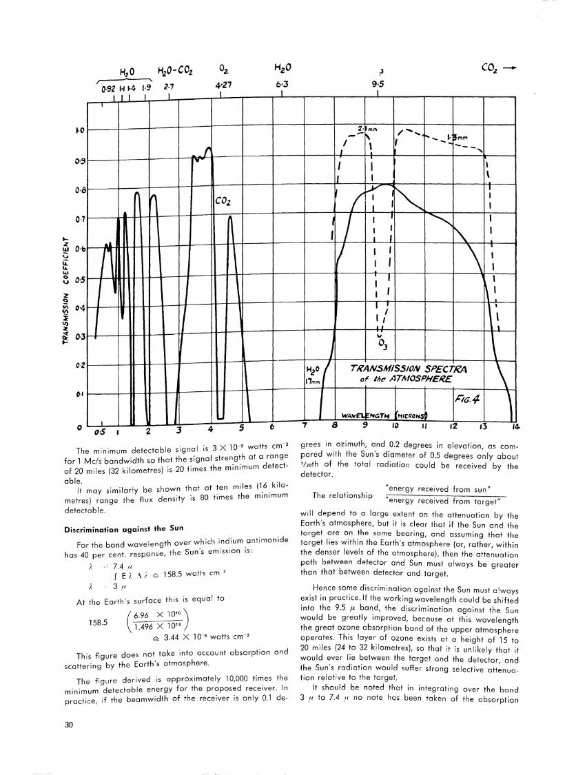
H2 0 HzO-COz Oz HzO
92 1-11-4 19 27 4•21 6·3 O· lll l _l _l _l
I
J.O
_f. 0-9 JV
O·B " /I. COz
0-7
I-..a.a z
O·b ~ r1 'J
ii: .... \l.I 0 0·5 u
2 ~
"' 0·4 U)
i II) z : 0-3 ....
O· z
0 ,,
0 ..1 J 4 5 6 o·S 2
. I . 3 X io-• watts cm-2 The minimum detectable s1gna is e
for l Meis bandwidth so that the signal_stren_g~h a~_adr~atn~t-) . 20 r the min1mur11 "'e of 20 miles (32 kilometres is imes
able. similar/ be shown that at ten miles (1_6. kilo-lt may theyflux density is 80 times the m1n1mum
metres) range detectabie.
Discrimination against the Sun
d I th over which indium antimonide For the ban wave eng . . · •h Sun's em1ss1on 1s: has 40 per cent. response, " e
i_ 7.4 /I 2
J E ;_ .\ i ~ 158.5 watts cm
}. 3 .LI
At the Earth's surface this is equai to
(6.96 x 10' 0 )
158.5 l .496 x l 013
~ 3.44 x l 0··5 watts cm-2
This figure does not take into account absorption and . b the Earth's atmosphere. scattering Y
The figure derived is approximately l 0,000 times the · · detectable energy for the proposed receiver. In
m1n1mum f h · · I Olde · ·f the beamwidth o t e receiver 1s on y . -practice, 1
30
7
:3 9·5 l
2· mm /-..... II:. 'T- - 1-pmm -'""t'
I \ -1- -t
I -~--~ -,
I I ll. I
,/ I
I ...1
~ \
'~ :
I I I
j
I I 1•
1/ ...LI.
TRANSMISSION SPECTRA of tit~ ATMOSPHERE
W;\~NGTH MICRO~ 8 9 10 II 12 13
\ .1.
l 14-
grees in azimuth, and 0.2 degrees in elevation, as compared with the Sun's diameter of 0.5 degrees only about 'hoth of the Iota! radiation could be received by the detector.
The relationship "energy received from sun"
"energy received from target"
wi 11 depend to a large extent on the attenuation by the Earth's atmosphere, but it is clear that if the Sun and the target are on the same bearing, and assuming that the target lies within the Earth's atmosphere (or, rather, within the denser levels of the atmosphere), then the attenuation path between detector and Sun must always be greater than that between detector and target.
Hence some discrimination against the Sun must always exist in practice. If the working wavelength could be shifted into the 9.5 µ band, the discrimination against the Sun would be greatly improved, because at this wavelength the great ozone absorption band of the upper atmosphere operates. Th is layer of ozone exists at a height of 15 to 20 miles (24 to 32 kilometres), so that it is unlikely that it would ever lie between the target and the detector, and the Sun's radiation would suffer strong selective attenuation relative to the target.
It should be noted that in integrating over the band 3 ,11 to 7.4 ,11 no note has been taken of the absorption
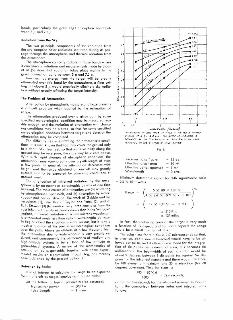
bands, particularly the great H,O absorption band between 5 11 and 7.5 /I.
Radiation from the Sky
The two principle components of the radiation from the sky comprise solar radiation scattered during its passage through the atmosphere, and thermal radiation from the atmosphere.
The atmosphere can only radiate in those bands where it can absorb radiation: and measurements made by Sloan et al [5] show that radiation takes place mainly in the great absorption band between 5 µ and 7.5 fl.
Inasmuch as energy from the target will be greatly attenuated over this band by the atmosphere, a filter cutting off above 5 fl would practically eliminate sky radiation without greatly affecting the target intensity.
The Problem of Attenuation
Attenuation by atmospheric moisture and haze presents a difficult problem when applied to the estimation of range.
The attenuation produced over a given path by some specified meteorological condition may be measured readily enough, and the variation of attenuation with changing conditions may be plotted, so that for some specified meteorological condition between target and detector the attenuation may be computed.
The difficulty lies in estimating the atmospheric conditions. It is well known that fog may cover the ground only to a depth of a few feet, so that while visibility along the ground may be very poor, the stars may be visible above. With such rapid changes of atmospheric conditions, the attenuation may vary greatly over a path length of even a few yards. In general, the attenuation decreases with height, and the range obtained on aircraft may greatly exceed that to be expected by observing conditions at ground level.
The attenuation of infra-red radiation by the atmosphere is by no means as catastrophic as was at one time believed. The main causes of attenuation are (a) scattering by atmospheric suspensoids, and (b) absorption by watervapour and carbon dioxide. The work of Gebbie and his associates [1], also that of Taylor and Yates [2], and of K. H. Stewart [3] (to mention only three examples from the vast infra-red literature) clearly shows that in the "window" regions, infra-red radiation of a few microns wavelength is attenuated much less than optical wavelengths by haze. In fog or cloud the situation is more serious, but it is very much a question of the precise meteorological conditions over the path. Above an altitude of a few thousand feet, the attenuation due to water-vapour is very greatly reduced, and consequently the performance of medium and high-altitude systems is better than of low altitude or ground-level systems. A review of the mathematics of attenuation by suspensoids, together with some experimental results on transmission through fog, has recently been published by the present author [4].
Detection by Radar
It is of interest to calculate the range to be expected for an aircraft as target, employing a pulsed radar.
Let the following typical parameters be assumed:
Transmitter power 500 Kw. Pulse Length = 1 ,11 sec.
i l -1
i
~ '---1-------tr---,'foT----+-T-~--.L__ iii 0·4~ ~ ! ~ 11 ;;; ~ il3 ·----
!': 02'>-----+-~__,-,..~ -·-~--!- ~ -I
·!' --- _L ~ 0·' ----I I
Z.18 I 3·o! I
o>---~'-----'-----------'----~l-~--05 2 3
/~cROIVS} 4
.-.f'4.\S.ll.'SS10,v c.: zccJ ~llR"3 o= ~-4ZE .\· .... ..,_: (',:_;, 4 \.:'.'iAK.£1>
WN.>cw.:s AT .2 .e,,.,.. & .~,-01...t. ~.,~ 5,-4r,e ~,: ,.,4z,.'\£SS .. ~
SP,e'c,.C.£.) B> -""!£ ':°-:f';/.\$/.fi~/ON 41 0·6i..t £ A~S .... 8'i V1SJ4._
:JErEcr:o~ .i'.ot\.JES t/ , ... CJT£D OIV ThE' C/;{'V~S
Fig. 5.
Receiver noise figure Effective target area Effective aeria I aperture Wavelength
12 db. 10 m2
1 m2
3 ems.
Minimum detectable signal for 3db signal/noise ratio 2.6 X l 0-13 watts.
R max 5Xl05 Xl023 Xl )'I• x 2.6 x 10·13 x 9 x l 0 '
17 X 1020 1/, = 105 2.15 )
_;- 215 Km. " 137 miles
In fact, the scattering area of the target is very much a function of its aspect, and for some aspects the range would be a small fraction of this.
The echo time for 215 Km is 717 microseconds so that, in practice, about one millisecond would have to be allowed per pulse, and if allowance is made for the integration of six pulses per element of scan, this becomes six milliseconds. The beamwidth of such a rndar would be about 2 degr-ees between 3 db points (as against 1/10 degrees for the infra-red scanner) and there would therefore be 180 elements in azimuth and 30 in elevation (for 60 degrees covernge). Time for scan rs:
180 ', 30 '< 6
1000 32.4 seconds,
as against five seconds for the infra-red scanner. In tabular form, the comparison between radar and infrared is as follows:
31
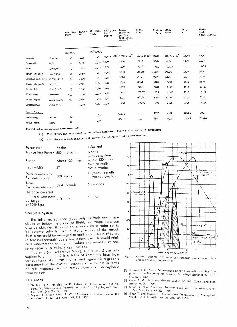
Air Hllss TbruSt SP. Fuel Galo, per Total hour calories
Total BTllU.
Approx, B?HU, H.P, l!!quiT.
EFF. i
Ila ate Heat
Flow KP. Cons. P<1r KP, per hr. (For total thrust).
(Mega llatta.)
KG/3oc.
Orenda 0 - 14 J450
1400
e ,'3 x irfa 3040 x io7 uo.6 x io6 0000 20,35 x io6 16.6i 29,4
14.9 Dassault
Fiat
R,7
4002,001
Prutt-",lhctne;· lS.7 P.lJ
General Electric J.?1. G::;.J
3tato ;,.ircra.ft :W.45
Japc.n Jet J - J - 1
Slaci:rurn
Rolls Ro:rce
Continental
:·:a.rbore
Avon RAo.29
7d
,'()
,u
l9
7,6
'/';:.
;l
325
4100
4UO
4760
420
1.09 10, 7
l • .!5 12.J
.s 7,84
• 9 s.B
1.0 'J.f:
1,00 10.6
l.~5 11.2
.76 7.6
1.1 10.8
1500
400
3890
3600
2650
1270
3720
452
59.5
154.36
142 •
105,1
50.3
17,77
l4T.6
17.94
J2~
754
11500
'l50C
6220
?25
11000
15,'32
7 .al
2.353
27.98
2.46
lJ.9
12.2
13.9
12.5
15.1
14,2
lJ,2
17.4
lJ.5
3.'!5
35.4
34.5
24.8
12.59
4.51
35,6
4.54
l'rop. Turbos.
r.riostrong .Jl
5(14,0 20, 1770
19?0
10,2
11.04 lv ,26 504.0 20.
10
T!-10 foL!.o·.ring o.sswpt1ona have been gade 1-
(a) That thl"'rnt can .,,, oquated to a<yniTalsnt horeeoowor for !l piston engine or tur~. (b) T.lu.t the \laste heat includes <lll losses, inclucling aircrui't power sernce•.
Parameter Radar
Transmitter Power 500 kilowatts
Range
Beamwidth
Discrimination at five miles range
Time for complete scan
Distance covered in time of one scan by target at 1 OOO f.p.s.
Complete System
About 130 miles
20
300 yards
22.4 seconds
61/i miles
Infra-red
None: passive system About 130 miles 1/10Q azimuth, '/s0 elevation
15 yards azimuth 30 yards elevation
5 seconds
1 mile
The infra-red scanner gives only azimuth and angle above or below the plane of flight, but range data can also be obtained if provision is made for a radar set to be automatically trained in the direction of the target. Such a set could be arranged to emit a short train of pulses (a few milliseconds) every ten seconds, which would minimise interference with other radars and would also preserve security in military applications.
Figures 3 (see reference No. 6), 4, 4 A and 5 are selfexplanatory; Figure 6 is a table of computed heat from various types of aircraft engine; and Figure 7 is a graphic assessment of the overall response of a system in terms of cell response, source temperature and atmospheric
transmission.
References [1] Gebbie, H. A., Harding, W.R., Hilsum, C., Pryce, A. W., and Ro·
berts, V., "Ati11ospheric Transmission in the 1 to 14 ~· Region" Proc. Roy. Soc., (A), 206, 87, (1950).
12] Taylor, J. H. and Yates, H. W., "Atmospheric Transmission in the Infra-red' J. Opt. Sec Amer., 47, 223, (1957).
32
·O
.l .l j
1' I I •I l J.... Ii ~-t.~o~·-•< I' I 7' 1\ ff 1~•P~~·- . -i ' I I 11~ I I I • I l ! I
I
~"I
O·S11111-V-i1tf'flt--fk-\-+-H~J1-t-1' ~:T';.__~_.JJ r?f t ~ ~ I'
0 ~ ~· ~- 111 1 '
Fig. 7. Overall response in terms of cell and atmospheric transmission. response source temperature
[3] Stewart, K. N. "Some Observations on the .. paper of the Meterological Research C ~ompos1tion of Fogs". A No. 1074, (1957). ommittee (London), M. R. P.
[4] Cade, C. M., ,,Infra-red Navigational A'd " B . Ironies, 6, 592, (1959). 1 s · nt. Comm. and Elec·
[5] Sloan, R. et al. "Infra-red Emission Spectrum J. Opt. Soc. Amre. 45, 455, 11955). of the Atmosphere".
[6] Elder, T. and Strong, J. "The Infra-red T . . W . d " J F ransm1ss1on of Atmosphe .·
in ows .. ranklin Institute, 255, 189, 11953). iic

introducing
I THE NEW GENERAL PRECISION MINIATURE INERTIAL PLATFORM Weighing only 14.3 pounds and occupying less than 113 of a cubic foot, the new MINS inertial platform, built by General Precision's Kearfott Division, achieves precise navigation with high reliability as well as the short ready time required by V / STOL aircraft. It is fully operational in 4.5 minutes from -65°F, draws only 64 watts during warm-up, and only 14 watts while running. Utilized in a pure inertial navigation system, MINS is compatible with analog or digital computers and with high performance Doppler inputs.
GENERAL PRECISION-A WORLD LEADER IN GUIDANCE AND CONTROL SYSTEMS One or more divisions of General Precision have designed and produced guidance and control systems, subsystems or components for every major aircraft, missile or space program. GPL Division is a leading producer of Doppler navigation. Librascope Division is a leader in airborne computers. In addition, Link Division designs and manufactures aircraft simulators which are used throughout the world for flight training purposes. General Precision capabilities and hardware are available throughout the free world with field service back-up of highest professional quality. General Precision, Inc., Tarrytown, New York, the principal operating subsidiary of General Precision Equipment Corporation.
GPL DIVISION KEARFOTT DIVISION LIBRASCOPE DIVISION LINK DIVISION COMMERCIAL COMPUTER DIVISION

Seventh National Meeting
of the Air Traffic Control Association
. A" Traffic Control From October 1 to 3 the American ir . . L
Association held its Seventh National MeetingMin . as V. p ident aurice
Vegas, Nevada. I FATCA's First ice res. f' A" T f-. I F derat1on o ir ra Cerf, represented the lnternat1ona e
fie Controllers Associations at the Conference.
The editor, unfortunately not having . be~n ~~let ~o attend the Conference himself, visited the Vice r~SI ue~t I~ Paris immediately after he had returned from t e II ni e f
.t Chief Contro er o States . Mr. Cerf, in his capac1 Y as f d h"mself
. · h" return oun 1 Paris Le Bourget airport, upon is .
. . k Th . t llat1on of a new confronted with quite some tas : e ins a . . IFR room at Le Bourget. Therefore he was nodt in ~ pot~;:
. t f our rea ers in tion to provide a written repor or d . . · I postponed, an we issue. However, this report is on Y h"I here hope that we can publish it in January. Meanw. 1 e, "th
I . f our di scussions w1 are a few remarks, resu ting rom "th the Maurice Cerf and from our correspondance wi
ATCA.
•• 1• · traffic control
The relationship of the c1v1 1an air . d for use of the system
system to the military services nee s h ATCA f t . at the Sevent absorbed a large share o atten ion
Conve ntion .
f d total over 1800, Preliminary es timates o atten ance d dd't' I
. t f s an a 1 1ona including over 1200 controller reg1s ra ion ' b hundreds of military controllers and aircrew memd ers,I
d ff . · 1 f om the Fe era industry representatives an o 1c1a s r t f the airways Government involved in managemen o
systems .
FAA Administrato r Halaby - who delivernd ~ ~·ajor speech th e evening of October 2 - led the list 0 igni-
tarie s.
34
Mr. Halaby's address at the banquet in his honor frankly outlined some of the hardships and dislocations which result from the FAA's Air Route Traffic Control Center consolidation program, which will reduce the present 29 to 21 in the future.
About 1400 controllers and their families, he said, will be uprooted by the move. Stressing the opportunities for career advancement inherent in the move, Halaby pointed out that the fewer, newer centers would handle more traffic, involve more people, and higher pay scales for the supervisory positions. He noted, however, that about 52 supervisors would become surplus in that capacity when the consolidation was completed. These men, Halaby said, will be placed "where their experience and capabilities can best be used ." He also hinted at the increasing FAA interest in management talents, as opposed to strict air traffic control technical knowledge, for filling the top administrative jobs.
Announced at the ATCA Convention was formation of sixteen local level Technical Advisory Groups of the ATCA National Advisory Committee to Industry. Originally organized on a national level this Spring, NACI will provide consultant and technical advisory service to industries developing equipment to update the air traffic control system. The Nat ional Group, with a staff composed of ATCA member controllers from the National Aviation Facilities Experimental Center near Atlantic City, New Jersey, has already been consulted by a major aviation electronics manufacturer. When fully implemented throughout the country, the local Technical Advisory Groups, affiliated with ATCA Chapters, will perform the advisory function in direct contact with manufacturers.
VERKEHRSFLUGHAFEN
FRANKFURT «RHEIN-MAIN»
1961
Flugzeug-99 872 bewegungen
2 570 330 Fluggaste
63 313 229 kg Luftfracht
17 171 756 kg Luftpost
rd .
rd .
1962 (geschatzt)
105 OOO
3 OOO OOO
rd . 80 OOO OOO kg
rd. 25 OOO OOO kg
Die zentraleuropaische Drehscheibe
des Weltluftverkehrs
EH

ATC test.
Instructor: "Do you know of any procedure to hold two aircraft in IMC at the same level over the same beacon, still maintaining standard separation?"
Student: "Affirmative, hold one aircraft standard, the other one non-standard."
* Running very tight approaches the controller all of
a sudden realizes that one bird is catching up rapidly to the aircraft in front: "Happyline 7 make a three-sixty to delay your flight for one minute." "Tower this is Happyline 7, you should know that a three-sixty takes us tho minutes." "Never mind sir, make a one-eighty and bring her in backwards."
* "Tower, do you have any traffic out here at my alti
tude?" "Negative, you are my only one." "Roger Tower, your only one is now turning final."
* A military aircraft with a high ranking VIP on board is expected to land very soon. Every 5 seconds the controller relays another questions from a military "operational control" station to the pilot. Each answer raises new questions and all of a sudden the pilot advises: "And you may also tell them that the pilot's license expires at 27th February 1963." Says the controller, rather excitedly as it seems: "You think you can reach your destination by that time?"
* Radar traffic information is one thing, its interpreta
tion is something else. "This is Bigfield Director, traffic information: an unidentified target, altitude unknown, at your 11 o'clock position."
"Thank you Bigfleld, is that time local or Zulu?"
* "Hotrod 709, do you have a VIP on board?" - "Nega-tive, we just have ADF, ILS, and VOR."
* Language difficulties apparently still exist rn aviation
now and then.
"Distinct 00011 this will be a surveillance approach to runway 14." "Whatdya mean clearing an Air Force aircraft for a civilian approach?"
* "Bigfield Tower, Chance 200 is on feenale." "Chance 200, roger, cleared to land." "Rrroger"
"Chance 200, apparently you are heading for some highway, not for the runway!"
"Rrroger"
"Chance 200, this is Bigfleld Tower, turn right imme-diately, the runway is half a mile to your right!"
"Rrroger, on short feenale." "Chance 200, pull up and go round again!" "Rr·roger, on very short feenale." Tower pr-esses crash button. "Chance 200, vee are overshooting, vy didn't you tell
us that there me cars on the runway?"
LORENZ seit mehr als 25 Jahren bahnbrechend in der Flugnavigation durch Funk
VOR I LS
FBI I ZFB
VD F 1 U D F 1
TACAN CONSOL
VH F-Drehfunkfeuer nach FAA Richtlinien Landefunkfeuer dem Dusenflugverkehr angepaBt Facherfunkfeuer und Z-Marker Mittelwellenfunkfeuer fUr Zielanfiuge GroBbasis-Doppler-Peiler im VH F-Bereich Grol3basis-Doppler-Peiler im UHF- Bereich Rho -Theta-System fur Mittelstrecken Funkfeuer fur Langstrecken
~SEL Standard Elektrik Lorenz AG Stuttgart
35
36
Corporation Members
of the International Federation
of Air Traffic Controllers' Associations
Cossor Radar and Electronics Limited,
Harlow, England
The Decca Navigator Company Limited,
London
KLM Royal Dutch Airlines
The Hague, Netherlands
Marcon i's Wireless Telegraph Company, Ltd.
Radar Division
Chelmsford, Essex, England
N.V. Hollandse Signaalapparaten
Hengelo, Netherlands
Texas Instruments Inc., Dallas 22, Texas, USA
The International Federation of Air Traffic Controllers' Associations would like to invite all corporations, organizations, and institutions interested in and concerned with the maintenance and promotion of safety in air traffic to ioin their organization as Corporation Members.
Corporation Members support the aims of the Federation by means of an annual subscription and bv supplying the Federation with technical information. The Federation's international iournal "The Con'troller" is offered as a platform for the discussion of technical and procedural developments in the
field of air traffic control.
For further information on Corporation Membership please contact Mr. H. W. Thau, Secretary, IFATCA,
Cologne-Wahn Airport, Germany.

the data link navigation system
KEEPS THE SITUATION UNDER CONTROL "Air Traffic Controllers are working at a level of s u stain e d pressure
and tension unequalled in aviation or a n y oth e r profess ion . . . "
Evidence s ubmitted to the U.S. Senate A viation Sub -committee on ATC
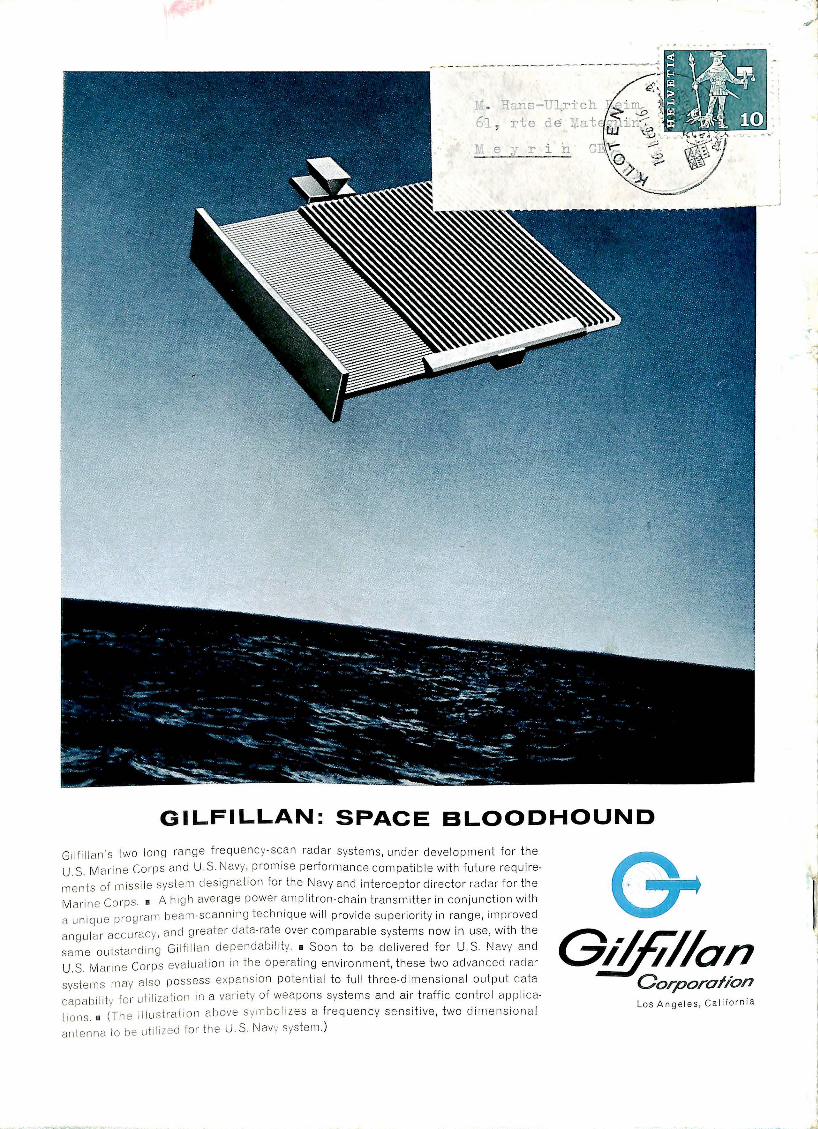
l" . Rans-U:lrich 61 , rte de Tiat
GILFILLAN: SPACE BLOODHOUND
Gil fillan's two long rnnge frequenc y-scan radar systems , under development for t he
U.S. Mmi ne Co1·ps an d U.S. Navy, promise peliormance compat ible with futu 1-e require
ments of miss il e system desi gnation to:· the Navy and interceptor director rndar for the
Mai· in e Co i·ps. • A h igh avernge powe1· amplitron -cha in trnnsmitter in conjunct ion with a uniq ue pi·ogrnm beam-scanning technique wil l provide supe1·iority in range, improved
angul ai- accu racy, and gi-eater data-rate over comparable systems now in use, with the
same outstanding Gi lfi I Ian clepenclab i I ity . • Soon to be de !ive1-ed for U.S. Navy and
U.S. Mai·in e Co1·ps evaluati on in the operating env ironment, these two advanced racl a1·
systems may also possess expansi on potent ial to full three-cli111e11siona l output data
capability fo 1- uti lization in a va1·iety of wea pons systems and ai1· fraffic contro l applica
tions. 0
(The illustration above sy111 boli zes a frequ ency sensitive, two d imensiona l
ante nn a to be utilized for· the U. S. Navy syste m.)
Gi/f/7/on Corporation Los Angeles, California