igcnewsletter issn 0972-5741 volume 122 october 2019 · • bits summer practice school at igcar...
TRANSCRIPT

IGCNewsletter
INDIRA GANDHI CENTRE FOR ATOMIC RESEARCHhttp://www.igcar.gov.in/lis/nl122/igc122.pdf
Technical Articles• Design and Development of Electron Impact Coupled Matrix Isolation
Infrared Spectroscopy: Exploration of ‘Dark’ Oxidation through the
Generation of Nascent Oxygen Atoms at Low Temperatures
• Development of Coupled System Dynamics and Computational Fluid
Dynamics Code to Address Thermal Stratification in Sodium Cooled Fast
Reactors
Young Officer’s Forum• Exploration of 2D Plasmon Nature of InN Nanostructures and their SERS
Activity
Young Researcher’s Forum• Electrodeposition of Platinum on Gas Diffusion Layer for the Application in
Proton Exchange Membrane Based Amperometric H2 Sensor
Conference and Meeting Highlights• National Conference on Light Matter Interaction at Nanoscale (LMIN-2019)
• National Technology Day Meet 2019
Training Programmes and Courses• Summer Training in Physics & Chemistry (STIPAC-2019)
• BITS Summer Practice School at IGCAR
• Bridge Course on ‘Welding and Fabrication’
• Eddy current Level-2 certification course
News and Events• Graduation Function of the 13th Batch of Trainee Scientific Officers of BARC
Training School at IGCAR
• Special Colloquium on March for Science
HBNI-IGCAR Corner
Awards & Honours
ISSN 0972-5741 Volume 122 October 2019
From the Editor
From the Editorial Committee
Dear Reader
It is our pleasant privilege to forward a copy of the latest issue of IGC Newsletter (Volume 122, October 2019 issue).
In the first technical article Dr. N. Ramanathan & colleagues, Materials Chemistry & Metal Fuel Cycle Group have discussed about the “Design and Development of Electron Impact Coupled Matrix Isolation Infrared Spectroscopy: Exploration of ‘Dark’ Oxidation through the Generation of Nascent Oxygen Atoms at Low Temperatures”.
In the second technical article Shri K. Natesan & colleagues, Reactor Design & Technology Group have discussed about the “Development of Coupled System Dynamics and Computational Fluid Dynamics Code to Address Thermal Stratification in Sodium Cooled Fast Reactors”.
Dr. Kishore Kumar Madapu, Materials Science Group has described about the “Exploration of 2D Plasmon Nature of InN Nanostructures and their SERS Activity” in the Young Officer’s Forum.
This issue’s Young Researcher’s Forum features an article by Ms. E. Jayanthi, Materials Chemistry & Metal Fuel Cycle Group, IGCAR discussing about the “Electrodeposition of Platinum on Gas Diffusion Layer for the Application in Proton Exchange Membrane Based Amperometric H2 Sensor”.
We are happy to share with you the awards, honours and distinctions earned by our colleagues.
We look forward to your comments, continued guidance and support.
With best wishes and personal regards
Editorial Committee, IGC Newsletter
IGC Newsletter
1
IGC Newsletter
matrix isolation set-up, a vacuum of 5 x 10⁻⁷ mbar was ensured
before performing the experiments. Using the third generation
electron gun assembly, a series of experiments were performed.
It was observed that due to the thermionic emission of electrons,
the temperature of the flange increased, which resulted in the
decomposition of high vacuum ‘Torr’ seal. Since the viton ‘O’-ring
connected to the flange was close to the filament, the heating
of the filament resulted in the deformation of the O’-ring, which
eventually demanded further modification of the electron gun
assembly.
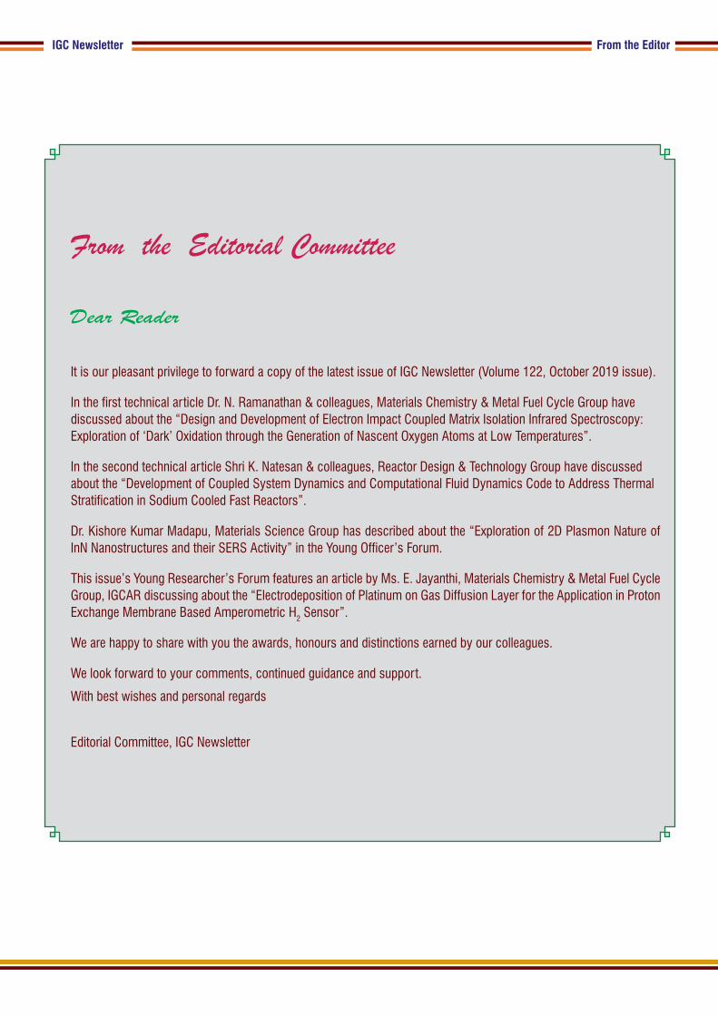
In the final design, we have addressed all these problems with high
vacuum feed through connector, which completely eliminated
the use of ‘Torr’ seal and the ‘O’-ring in the area adjoining the
filament. The design drawings of the fourth generation electron
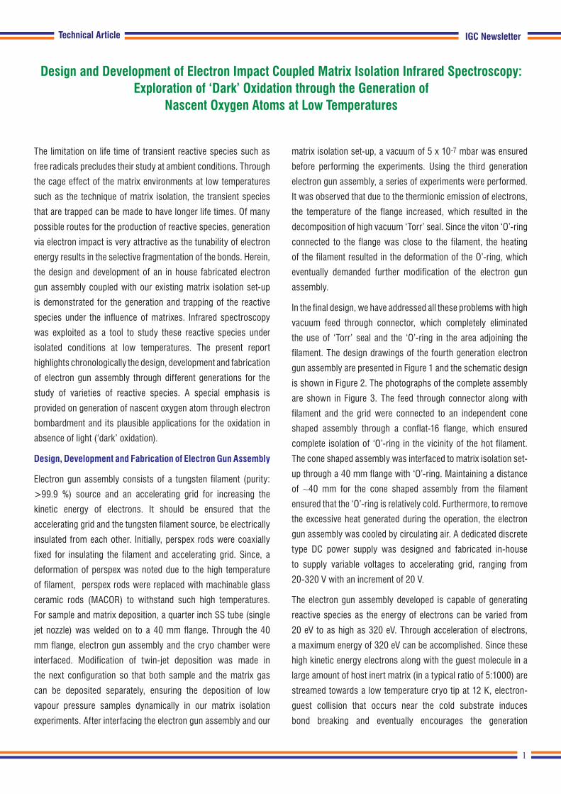
gun assembly are presented in Figure 1 and the schematic design
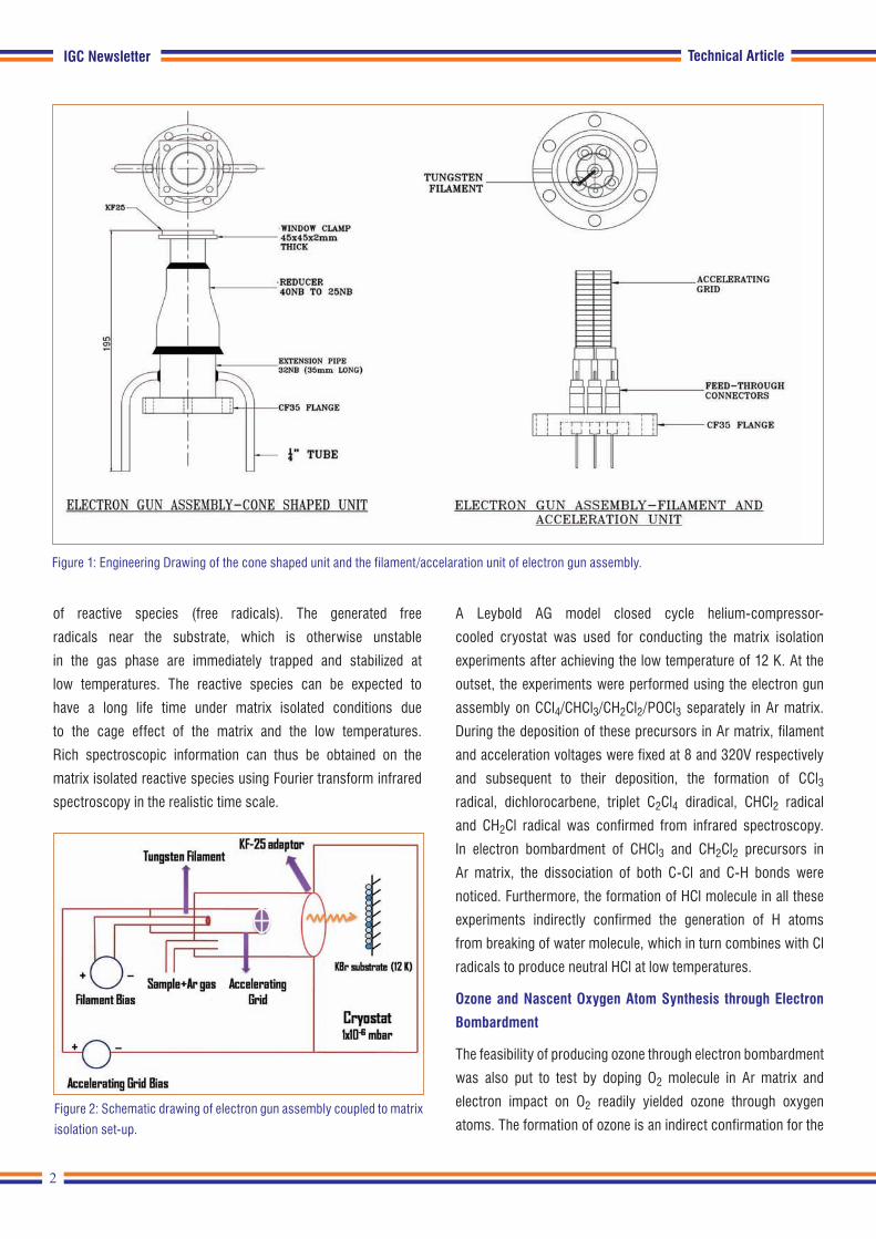
is shown in Figure 2. The photographs of the complete assembly
are shown in Figure 3. The feed through connector along with
filament and the grid were connected to an independent cone
shaped assembly through a conflat-16 flange, which ensured
complete isolation of ‘O’-ring in the vicinity of the hot filament.
The cone shaped assembly was interfaced to matrix isolation set-
up through a 40 mm flange with ‘O’-ring. Maintaining a distance
of ~40 mm for the cone shaped assembly from the filament
ensured that the ‘O’-ring is relatively cold. Furthermore, to remove
the excessive heat generated during the operation, the electron
gun assembly was cooled by circulating air. A dedicated discrete
type DC power supply was designed and fabricated in-house
to supply variable voltages to accelerating grid, ranging from
20-320 V with an increment of 20 V.
The electron gun assembly developed is capable of generating
reactive species as the energy of electrons can be varied from
20 eV to as high as 320 eV. Through acceleration of electrons,
a maximum energy of 320 eV can be accomplished. Since these
high kinetic energy electrons along with the guest molecule in a
large amount of host inert matrix (in a typical ratio of 5:1000) are
streamed towards a low temperature cryo tip at 12 K, electron-
guest collision that occurs near the cold substrate induces
bond breaking and eventually encourages the generation
The limitation on life time of transient reactive species such as
free radicals precludes their study at ambient conditions. Through
the cage effect of the matrix environments at low temperatures
such as the technique of matrix isolation, the transient species
that are trapped can be made to have longer life times. Of many
possible routes for the production of reactive species, generation
via electron impact is very attractive as the tunability of electron
energy results in the selective fragmentation of the bonds. Herein,
the design and development of an in house fabricated electron
gun assembly coupled with our existing matrix isolation set-up
is demonstrated for the generation and trapping of the reactive
species under the influence of matrixes. Infrared spectroscopy
was exploited as a tool to study these reactive species under
isolated conditions at low temperatures. The present report
highlights chronologically the design, development and fabrication
of electron gun assembly through different generations for the
study of varieties of reactive species. A special emphasis is
provided on generation of nascent oxygen atom through electron
bombardment and its plausible applications for the oxidation in
absence of light (‘dark’ oxidation).
Design, Development and Fabrication of Electron Gun Assembly
Electron gun assembly consists of a tungsten filament (purity:
>99.9 %) source and an accelerating grid for increasing the
kinetic energy of electrons. It should be ensured that the
accelerating grid and the tungsten filament source, be electrically
insulated from each other. Initially, perspex rods were coaxially
fixed for insulating the filament and accelerating grid. Since, a
deformation of perspex was noted due to the high temperature
of filament, perspex rods were replaced with machinable glass
ceramic rods (MACOR) to withstand such high temperatures.
For sample and matrix deposition, a quarter inch SS tube (single
jet nozzle) was welded on to a 40 mm flange. Through the 40
mm flange, electron gun assembly and the cryo chamber were
interfaced. Modification of twin-jet deposition was made in
the next configuration so that both sample and the matrix gas
can be deposited separately, ensuring the deposition of low
vapour pressure samples dynamically in our matrix isolation
experiments. After interfacing the electron gun assembly and our
Technical Article
Design and Development of Electron Impact Coupled Matrix Isolation Infrared Spectroscopy: Exploration of ‘Dark’ Oxidation through the Generation of
Nascent Oxygen Atoms at Low Temperatures
2
IGC Newsletter
of reactive species (free radicals). The generated free
radicals near the substrate, which is otherwise unstable
in the gas phase are immediately trapped and stabilized at
low temperatures. The reactive species can be expected to
have a long life time under matrix isolated conditions due
to the cage effect of the matrix and the low temperatures.
Rich spectroscopic information can thus be obtained on the
matrix isolated reactive species using Fourier transform infrared
spectroscopy in the realistic time scale.
A Leybold AG model closed cycle helium-compressor-
cooled cryostat was used for conducting the matrix isolation
experiments after achieving the low temperature of 12 K. At the
outset, the experiments were performed using the electron gun
assembly on CCl4/CHCl3/CH2Cl2/POCl3 separately in Ar matrix.
During the deposition of these precursors in Ar matrix, filament
and acceleration voltages were fixed at 8 and 320V respectively
and subsequent to their deposition, the formation of CCl3
radical, dichlorocarbene, triplet C2Cl4 diradical, CHCl2 radical
and CH2Cl radical was confirmed from infrared spectroscopy.
In electron bombardment of CHCl3 and CH2Cl2 precursors in
Ar matrix, the dissociation of both C-Cl and C-H bonds were
noticed. Furthermore, the formation of HCl molecule in all these
experiments indirectly confirmed the generation of H atoms
from breaking of water molecule, which in turn combines with Cl
radicals to produce neutral HCl at low temperatures.
Ozone and Nascent Oxygen Atom Synthesis through Electron
Bombardment
The feasibility of producing ozone through electron bombardment
was also put to test by doping O2 molecule in Ar matrix and
electron impact on O2 readily yielded ozone through oxygen
atoms. The formation of ozone is an indirect confirmation for the
Technical Article
Figure 1: Engineering Drawing of the cone shaped unit and the filament/accelaration unit of electron gun assembly.
Figure 2: Schematic drawing of electron gun assembly coupled to matrix
isolation set-up.
3
IGC NewsletterTechnical Article
generation of nascent oxygen atoms. It was discerned that the
yield of ozone is strongly dependent on the acceleration voltage
and the rate of deposition. In order to confirm the production of
oxygen atoms, oxidation was performed at low temperatures.
PCl3 molecule can be thought of as the prototype to test for
the generation of oxygen atoms as PCl3 can be oxidized readily
to POCl3 in presence of oxygen atoms. An oxidation of PCl3 to
POCl3 was therefore accomplished in the absence of light through
electron bombardment of O2 doped Ar matrix. Generation of
oxygen atoms and ozone is first of its kind through electron
bombardment with ‘soft (low energy) electrons’ under matrix
isolated conditions in contrast to ozone synthesis from solid O2
at 11 K with high energy 5 KeV electrons as reported earlier in the
literature.
Oxidation of CCl4 through Electron Bombardment
Subsequent to the oxidation of PCl3 to POCl3 (where the formation
of pentavalent phosphorus from its trivalent state is due to the
availability of vacant ‘d’ orbital), it will be intriguing to examine the
Figure 3: Photograph showing the electron gun assembly in parts: A) Tungsten filament B) Accelerating grid C) Top view of feed through connector on
which filament and accelerating grids are connected D) Complete electron gun assembly E) Coupling of electron gun assembly and matrix isolation
set-up F) Matrix isolation experiments with electron gun assembly
oxidation of analogous carbon compound (CCl4) in the tetravalent
state, in which the central carbon does not possess a vacant ‘d’
orbital. A similar oxidation of CCl4 in presence of oxygen atoms in
absence of light was therefore attempted by co-depositing CCl4
with 5% oxygen in Ar matrix by keeping the electron gun ‘on’. As
the electron bombardment of CCl4 produces CCl3 radical with a
larger yield through C-Cl bond breaking, the nascent oxygen atom
available can induce reactions yielding radicals/neutral species.
Figure 4, trace ‘a’ shows the infrared spectrum of CCl4 without
electron bombardment, trace ‘b’ represents the spectrum
with electron bombardment in 16O2 doped CCl4 and trace ‘c’
displays the spectrum with electron bombardment in isotopically
substituted 18O2 doped CCl4 in Ar matrix. In contrast to the direct
oxygen addition on PCl3, which produced POCl3, the electron
bombardment of CCl4 triggered the formation of phosgene
(COCl2) in Ar matrix. The spectral features observed at 1815.4,
1814.1, 1812.1, 837.3 and 836.4 cm-1 are due to COCl2, which
was confirmed through both literature report and ab initio
computations performed at MP2 level of theory with aug-cc-

4
IGC Newsletter Technical Article
pVDZ basis set. The spectral bands appearing at 1039.7 and
1033.2 cm-1 correspond to O3 and O3…O complex respectively.
On 18O isotopic substitution, the spectral features of C18OCl2 was
shifted to 1777.8, 1776.9, 1776.1, 834.7 and 833.7 cm-1, whereas 18O3 and 18O3…18O complex correspond to 982.4 and 976.3 cm-1
respectively. As 18O2 doping experiments have small amount of 16O2 impurity, the mixture of features due to C16OCl2 and C18OCl2
were noticed (trace ‘c’ in Figure 4). Likewise, O3 also has various
isotopic combinations, which are marked with asterisk in trace
‘c’ of Figure 4. Since, COCl2 generation warrants the breaking
of two C-Cl bonds, the mechanism of the formation of COCl2
from CCl4 should be very different from POCl3 formation through
direct oxygen atom addition on PCl3. The following mechanism is
therefore proposed for the formation COCl2 molecule.
CCl4 + e- → CCl3. + Cl.+e-
O2 + e- → 2O. + e-
O2 + O → O3
CCl3. + O → COCl3.→ COCl2 + Cl.
In addition to the said discussed features, the spectral features
that correspond to 1105.5, 1101.7, 1094.0 and 1090.4 cm-1 with
an isotopic shift of 1068.6, 1064.9, 1056.8 and 1053.2 cm-1
respectively are attributable to stable Cl2O4 dimer, which is
expected to be formed from a relatively unstable ClO2 radical.
2Cl. + 4O → 2ClO2.→ Cl2O4
Apart from the spectral features explored, the infrared bands that
were observed at 1010.0, 1004.3 and 848.5 cm-1 with an isotopic
shift of 986.2 and 846.0 cm-1 could not be clearly assigned for
any specific specie of oxygen formed through radicals of CCl4.
Even though, COCl3 radical was thought to be the possible
contender and since the formation of the stable COCl2 product
can be ascribed only via COCl3 radical intermediate, the trapping
of COCl3 radical at low temperatures can be ruled out. Since,
multitude of possibilities can be thought of during the electron
bombardment of CCl4 in Ar matrix in presence of oxygen; those
spectral features are left unassigned.
An electron gun assembly was designed, developed and
fabricated in-house and was successfully tested by coupling with
our existing matrix isolation facility for the generation of diverse
reactive species. Oxygen atom generation was also accomplished
by breaking the oxygen molecule through electron collision, which
opens up avenues in exploring ‘dark’ oxidation of molecules in the
absence of light. Subsequently, an oxidation was accomplished
in ‘dark’ by generating oxygen atoms and CCl3 radical through
electron bombardment of CCl4 with O2 molecule in Ar matrix and
the products were characterized using infrared spectroscopy.
Phosgene was the product, produced predominantly through this
oxidation. Cl2O4 (dimer of ClO2) also was generated with a small
yield. Overall, the ‘dark’ oxidation described in this work through
electron bombardment is very powerful for the generation of
the species, which are otherwise difficult to be produced and
stabilized at ambient conditions upon its generation.
Reported by
Dr. N. Ramanathan & colleagues,
Materials Chemistry & Metal Fuel Cycle Group
Figure 4. The infrared spectra of matrix isolated CCl4/16O2/Ar (5/50/1000)
a) without electron impact b) with electron impact using a filament
voltage of 8 V and acceleration voltage of 320 V during deposition c)
matrix isolated CCl4/18O2/Ar (5/50/1000) with electron impact. The
features marked with asterisk are due to various isotopic combinations
of O3. The features marked with ‘?’ are left unassigned
5
IGC Newsletter
Following this, cold sodium starts emanating from the reactor core due to loss of heating. Thus, adverse buoyancy conditions would be developed on the cold sodium flow emanating from the core and this makes it difficult to penetrate through the hot sodium prevailing in hot pool. This results in transient thermal stratification of hot pool. Due to the large size of pool, this phenomenon is more pronounced in pool type compared to loop type reactors.
Stratification during steady state operation
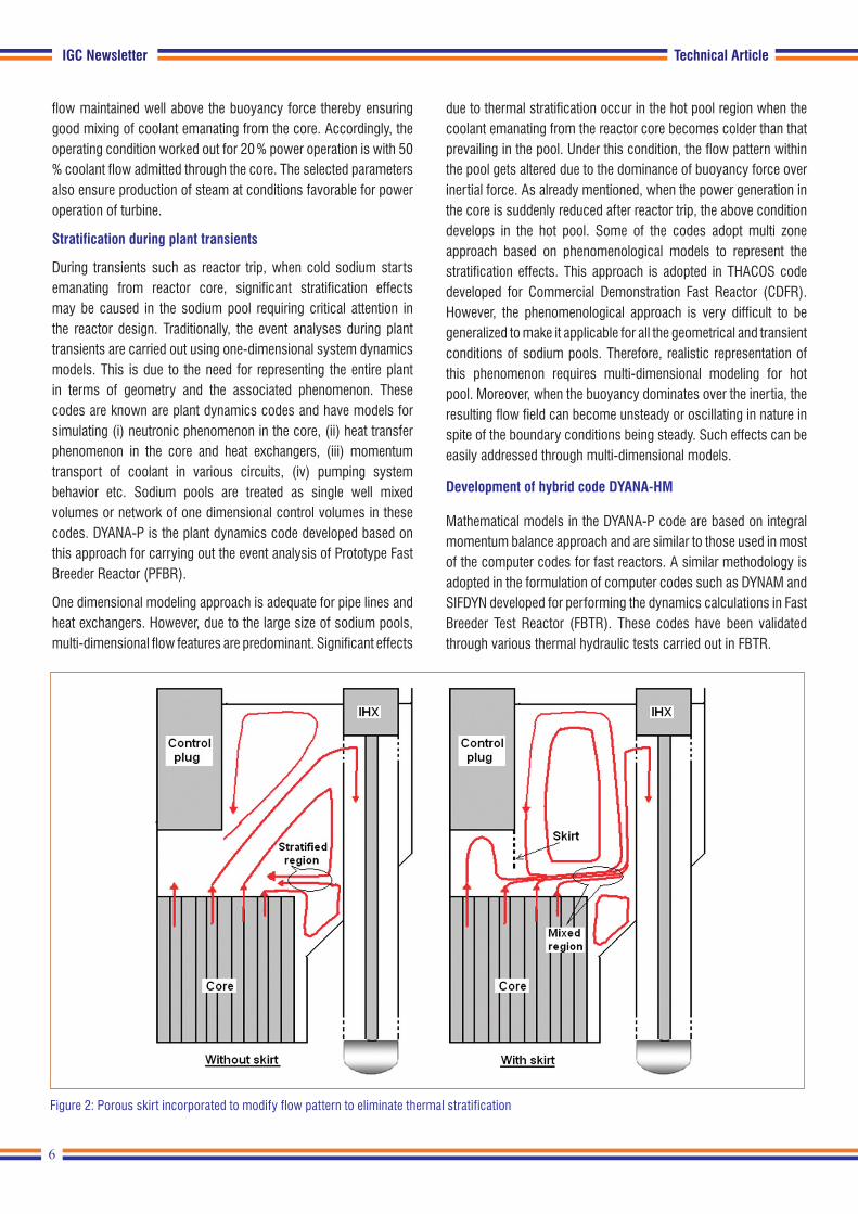
Thermal stratification in sodium pool can be prevented if inertial force of coolant flow emanating from core is made to dominate over buoyancy or the development of adverse buoyancy conditions is avoided. The primary approach taken in the design is to eliminate the conditions leading to formation of thermal stratification layers. If this is not feasible, the approach is to consider the resulting thermo-mechanical loads in the component design. Based on the detailed thermal hydraulic investigations of hot pool, a porous skirt is introduced below control plug in the design as shown in Figure 2 to eliminate the formation of thermal stratification layers during normal operating conditions of the reactor. The porous skirt diverts the flow and induces mixing of coolant streams emanating from various subassemblies thereby eliminating the development of adverse buoyancy conditions. The configuration of the skirt is worked out based on pool hydraulics studies carried out for full power operating conditions of the reactor. However, the reactor may also be operating at low power conditions as well. Hence, it is essential to establish that the stratification do not arise under these conditions also. For this, the approach adopted is to operate the reactor under part load conditions with inertial force of the coolant
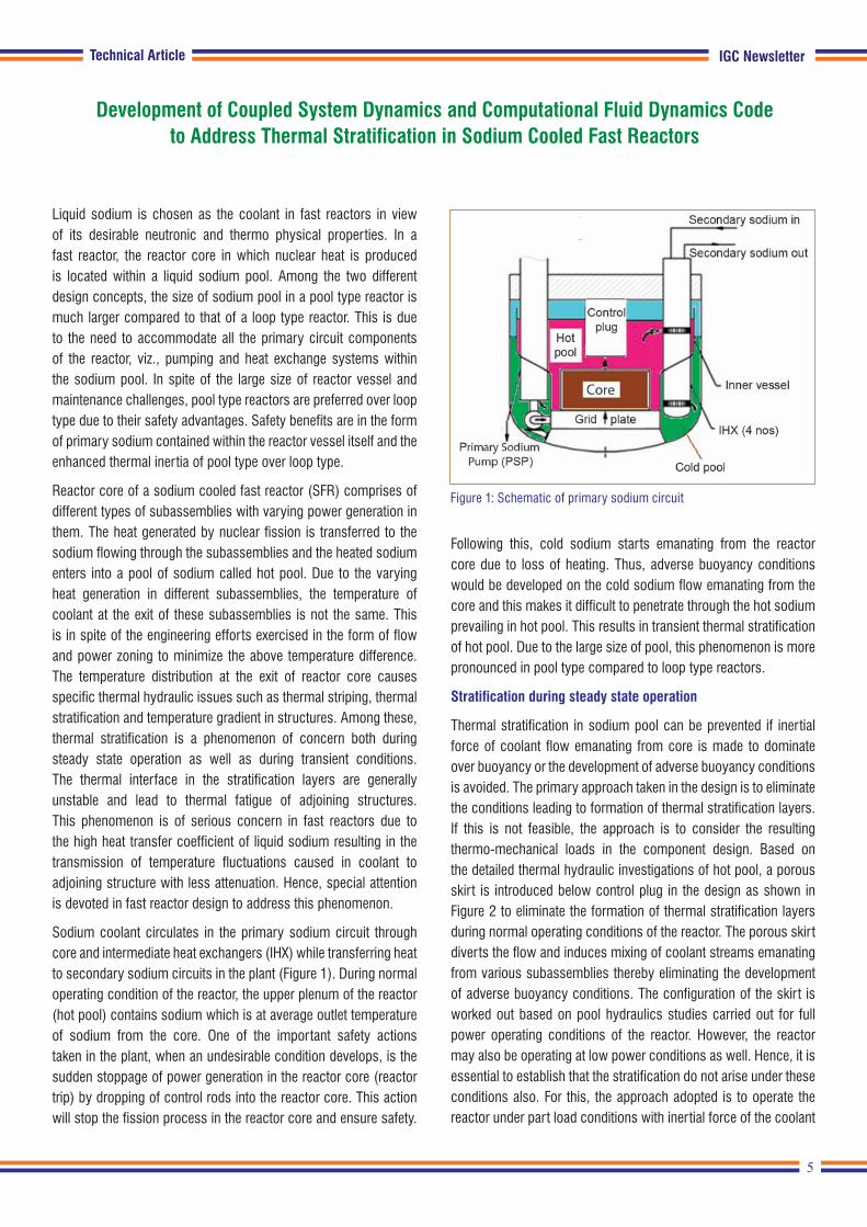
Liquid sodium is chosen as the coolant in fast reactors in view of its desirable neutronic and thermo physical properties. In a fast reactor, the reactor core in which nuclear heat is produced is located within a liquid sodium pool. Among the two different design concepts, the size of sodium pool in a pool type reactor is much larger compared to that of a loop type reactor. This is due to the need to accommodate all the primary circuit components of the reactor, viz., pumping and heat exchange systems within the sodium pool. In spite of the large size of reactor vessel and maintenance challenges, pool type reactors are preferred over loop type due to their safety advantages. Safety benefits are in the form of primary sodium contained within the reactor vessel itself and the enhanced thermal inertia of pool type over loop type.
Reactor core of a sodium cooled fast reactor (SFR) comprises of different types of subassemblies with varying power generation in them. The heat generated by nuclear fission is transferred to the sodium flowing through the subassemblies and the heated sodium enters into a pool of sodium called hot pool. Due to the varying heat generation in different subassemblies, the temperature of coolant at the exit of these subassemblies is not the same. This is in spite of the engineering efforts exercised in the form of flow and power zoning to minimize the above temperature difference. The temperature distribution at the exit of reactor core causes specific thermal hydraulic issues such as thermal striping, thermal stratification and temperature gradient in structures. Among these, thermal stratification is a phenomenon of concern both during steady state operation as well as during transient conditions. The thermal interface in the stratification layers are generally unstable and lead to thermal fatigue of adjoining structures. This phenomenon is of serious concern in fast reactors due to the high heat transfer coefficient of liquid sodium resulting in the transmission of temperature fluctuations caused in coolant to adjoining structure with less attenuation. Hence, special attention is devoted in fast reactor design to address this phenomenon.
Sodium coolant circulates in the primary sodium circuit through core and intermediate heat exchangers (IHX) while transferring heat to secondary sodium circuits in the plant (Figure 1). During normal operating condition of the reactor, the upper plenum of the reactor (hot pool) contains sodium which is at average outlet temperature of sodium from the core. One of the important safety actions taken in the plant, when an undesirable condition develops, is the sudden stoppage of power generation in the reactor core (reactor trip) by dropping of control rods into the reactor core. This action will stop the fission process in the reactor core and ensure safety.
Development of Coupled System Dynamics and Computational Fluid Dynamics Code to Address Thermal Stratification in Sodium Cooled Fast Reactors
Technical Article
Figure 1: Schematic of primary sodium circuit
6
IGC Newsletter Technical Article
flow maintained well above the buoyancy force thereby ensuring good mixing of coolant emanating from the core. Accordingly, the operating condition worked out for 20 % power operation is with 50 % coolant flow admitted through the core. The selected parameters also ensure production of steam at conditions favorable for power operation of turbine.
Stratification during plant transients
During transients such as reactor trip, when cold sodium starts emanating from reactor core, significant stratification effects may be caused in the sodium pool requiring critical attention in the reactor design. Traditionally, the event analyses during plant transients are carried out using one-dimensional system dynamics models. This is due to the need for representing the entire plant in terms of geometry and the associated phenomenon. These codes are known are plant dynamics codes and have models for simulating (i) neutronic phenomenon in the core, (ii) heat transfer phenomenon in the core and heat exchangers, (iii) momentum transport of coolant in various circuits, (iv) pumping system behavior etc. Sodium pools are treated as single well mixed volumes or network of one dimensional control volumes in these codes. DYANA-P is the plant dynamics code developed based on this approach for carrying out the event analysis of Prototype Fast Breeder Reactor (PFBR).
One dimensional modeling approach is adequate for pipe lines and heat exchangers. However, due to the large size of sodium pools, multi-dimensional flow features are predominant. Significant effects
due to thermal stratification occur in the hot pool region when the coolant emanating from the reactor core becomes colder than that prevailing in the pool. Under this condition, the flow pattern within the pool gets altered due to the dominance of buoyancy force over inertial force. As already mentioned, when the power generation in the core is suddenly reduced after reactor trip, the above condition develops in the hot pool. Some of the codes adopt multi zone approach based on phenomenological models to represent the stratification effects. This approach is adopted in THACOS code developed for Commercial Demonstration Fast Reactor (CDFR). However, the phenomenological approach is very difficult to be generalized to make it applicable for all the geometrical and transient conditions of sodium pools. Therefore, realistic representation of this phenomenon requires multi-dimensional modeling for hot pool. Moreover, when the buoyancy dominates over the inertia, the resulting flow field can become unsteady or oscillating in nature in spite of the boundary conditions being steady. Such effects can be easily addressed through multi-dimensional models.
Development of hybrid code DYANA-HM
Mathematical models in the DYANA-P code are based on integral momentum balance approach and are similar to those used in most of the computer codes for fast reactors. A similar methodology is adopted in the formulation of computer codes such as DYNAM and SIFDYN developed for performing the dynamics calculations in Fast Breeder Test Reactor (FBTR). These codes have been validated through various thermal hydraulic tests carried out in FBTR.
Figure 2: Porous skirt incorporated to modify flow pattern to eliminate thermal stratification

7
IGC NewsletterTechnical Article
Figure 3: Nodalisation scheme in DYANA-P with respect to single primary and secondary sodium circuits of a pool type fast reactor
Thermal models are based on heat balance between various sections exchanging the heat such as fuel and sodium through the clad in subassembly, primary sodium and secondary sodium through the tube wall in IHX, sodium and ambient air through the pipe wall and insulation in sodium piping, secondary sodium and water through the tube wall in steam generators (SG) etc. Hydraulic model is based on momentum balance between various flow segments in the primary and secondary sodium circuits. Torque balance is adopted for the modelling of pump with the characteristics derived from generalized homologous characteristics. Fluid levels in the tanks are modelled through dynamic mass balance. Neutronic model for the core is based on point kinetics approximation. Transient solution is obtained by prompt jump approximation. Detailed models are also incorporated for the calculation of various reactivity feedback effects due to radial expansion of grid plate in which the reactor core is supported, relative thermal expansion between main vessel and control rods, volumetric expansion of sodium contained in the reactor core, axial expansion of core structures, axial expansion of fuel and Doppler effect due to changes in fuel temperature. Nodalization scheme adopted in the code for the modelling of a pool type fast reactor is shown in Figure 3.
The codes which are intended to address thermal stratification behaviour of sodium pools adopt multi zone or CFD based multi-dimensional models for representing the thermal hydraulics of sodium pools. Detailed studies carried out earlier have revealed that two-dimensional (2D axi-symmetric) modelling approach for hot pool is adequate to accurately represent the thermal stratification conditions in the hot pool of a fast reactor. Therefore, a coupled code system named DYANA-HM with 2D model for hot pool and one dimensional (1D) models for rest of the plant has been developed for carrying out plant dynamics studies for a pool type fast reactor. The one dimensional formulation adopted in the code has been validated against end of life studies carried out in the French fast reactor PHENIX.
Axi-symmetric model developed for hot pool solves governing equations for continuity, momentum balance and energy balance along with adequate treatment of turbulence. For this, the generic k-ε based turbulence model is adopted. Effect of buoyancy on sodium flow in the pool is modelled through Boussinesq approximation with appropriate source term considered in the axial momentum balance equation. The governing equations are discretised through finite volume method adopting staggered mesh approach for continuity and momentum balance equations.
8
IGC Newsletter
Figure 5: Model architecture of DYANA-HM
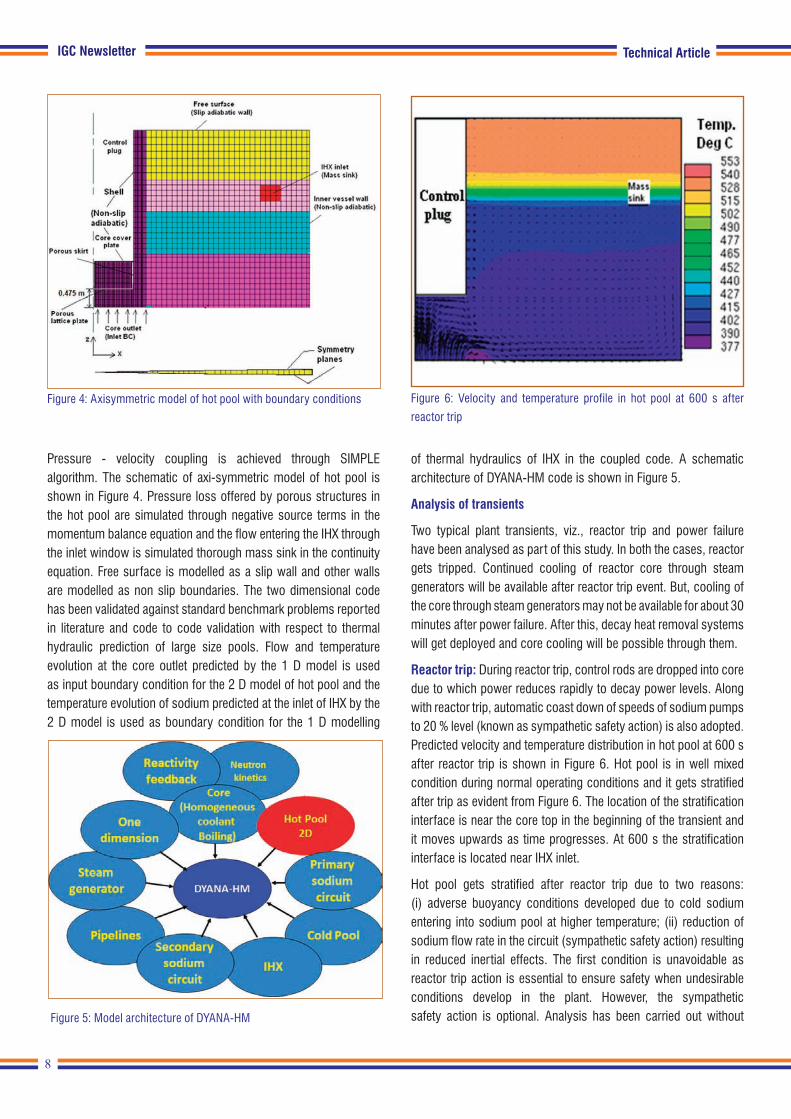
Pressure - velocity coupling is achieved through SIMPLE algorithm. The schematic of axi-symmetric model of hot pool is shown in Figure 4. Pressure loss offered by porous structures in the hot pool are simulated through negative source terms in the momentum balance equation and the flow entering the IHX through the inlet window is simulated thorough mass sink in the continuity equation. Free surface is modelled as a slip wall and other walls are modelled as non slip boundaries. The two dimensional code has been validated against standard benchmark problems reported in literature and code to code validation with respect to thermal hydraulic prediction of large size pools. Flow and temperature evolution at the core outlet predicted by the 1 D model is used as input boundary condition for the 2 D model of hot pool and the temperature evolution of sodium predicted at the inlet of IHX by the 2 D model is used as boundary condition for the 1 D modelling
of thermal hydraulics of IHX in the coupled code. A schematic architecture of DYANA-HM code is shown in Figure 5.
Analysis of transients
Two typical plant transients, viz., reactor trip and power failure have been analysed as part of this study. In both the cases, reactor gets tripped. Continued cooling of reactor core through steam generators will be available after reactor trip event. But, cooling of the core through steam generators may not be available for about 30 minutes after power failure. After this, decay heat removal systems will get deployed and core cooling will be possible through them.
Reactor trip: During reactor trip, control rods are dropped into core due to which power reduces rapidly to decay power levels. Along with reactor trip, automatic coast down of speeds of sodium pumps to 20 % level (known as sympathetic safety action) is also adopted. Predicted velocity and temperature distribution in hot pool at 600 s after reactor trip is shown in Figure 6. Hot pool is in well mixed condition during normal operating conditions and it gets stratified after trip as evident from Figure 6. The location of the stratification interface is near the core top in the beginning of the transient and it moves upwards as time progresses. At 600 s the stratification interface is located near IHX inlet.
Hot pool gets stratified after reactor trip due to two reasons: (i) adverse buoyancy conditions developed due to cold sodium entering into sodium pool at higher temperature; (ii) reduction of sodium flow rate in the circuit (sympathetic safety action) resulting in reduced inertial effects. The first condition is unavoidable as reactor trip action is essential to ensure safety when undesirable conditions develop in the plant. However, the sympathetic safety action is optional. Analysis has been carried out without
Figure 6: Velocity and temperature profile in hot pool at 600 s after
reactor trip
Technical Article
Figure 4: Axisymmetric model of hot pool with boundary conditions
9
IGC Newsletter
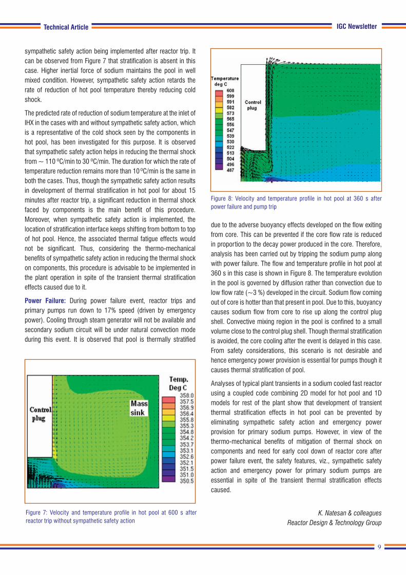
sympathetic safety action being implemented after reactor trip. It can be observed from Figure 7 that stratification is absent in this case. Higher inertial force of sodium maintains the pool in well mixed condition. However, sympathetic safety action retards the rate of reduction of hot pool temperature thereby reducing cold shock.
The predicted rate of reduction of sodium temperature at the inlet of IHX in the cases with and without sympathetic safety action, which is a representative of the cold shock seen by the components in hot pool, has been investigated for this purpose. It is observed that sympathetic safety action helps in reducing the thermal shock from ~ 110 ºC/min to 30 ºC/min. The duration for which the rate of temperature reduction remains more than 10 ºC/min is the same in both the cases. Thus, though the sympathetic safety action results in development of thermal stratification in hot pool for about 15 minutes after reactor trip, a significant reduction in thermal shock faced by components is the main benefit of this procedure. Moreover, when sympathetic safety action is implemented, the location of stratification interface keeps shifting from bottom to top of hot pool. Hence, the associated thermal fatigue effects would not be significant. Thus, considering the thermo-mechanical benefits of sympathetic safety action in reducing the thermal shock on components, this procedure is advisable to be implemented in the plant operation in spite of the transient thermal stratification effects caused due to it.
Power Failure: During power failure event, reactor trips and primary pumps run down to 17% speed (driven by emergency power). Cooling through steam generator will not be available and secondary sodium circuit will be under natural convection mode during this event. It is observed that pool is thermally stratified
due to the adverse buoyancy effects developed on the flow exiting from core. This can be prevented if the core flow rate is reduced in proportion to the decay power produced in the core. Therefore, analysis has been carried out by tripping the sodium pump along with power failure. The flow and temperature profile in hot pool at 360 s in this case is shown in Figure 8. The temperature evolution in the pool is governed by diffusion rather than convection due to low flow rate (~3 %) developed in the circuit. Sodium flow coming out of core is hotter than that present in pool. Due to this, buoyancy causes sodium flow from core to rise up along the control plug shell. Convective mixing region in the pool is confined to a small volume close to the control plug shell. Though thermal stratification is avoided, the core cooling after the event is delayed in this case. From safety considerations, this scenario is not desirable and hence emergency power provision is essential for pumps though it causes thermal stratification of pool.
Analyses of typical plant transients in a sodium cooled fast reactor using a coupled code combining 2D model for hot pool and 1D models for rest of the plant show that development of transient thermal stratification effects in hot pool can be prevented by eliminating sympathetic safety action and emergency power provision for primary sodium pumps. However, in view of the thermo-mechanical benefits of mitigation of thermal shock on components and need for early cool down of reactor core after power failure event, the safety features, viz., sympathetic safety action and emergency power for primary sodium pumps are essential in spite of the transient thermal stratification effects caused.
K. Natesan & colleagues
Reactor Design & Technology Group
Figure 8: Velocity and temperature profile in hot pool at 360 s after power failure and pump trip
Technical Article
Figure 7: Velocity and temperature profile in hot pool at 600 s after reactor trip without sympathetic safety action

10
IGC Newsletter
Exploration of 2D Plasmon Nature of InN Nanostructures and their SERS Activity
Young Officer’s FORUM
In the last decade, surface plasmons (SPs) are widely studied because of its potentiality in the miniaturization of photonic devices and other widespread applications in multiple fields like biological and chemical sensing. The SP is collective oscillations of conduction band electrons excited by the electromagnetic waves. The SPs have the two fundamental excitations such as localized surface plasmon resonance (LSPR) and propagating surface plasmon polaritons (SPPs). The LSPR is excited when the size of nanoparticles are significantly less than the wavelength of the exciting light, where it experiences a uniform electric field, and frequency of the electromagnetic wave matches with the resonance frequency of nanoparticles. The important applications of the LSPR are realized from the strong extinction of the electric field and subsequent enhancement of the local electric field around the nanoparticles in the near-field (Figure 1a, Top). The strong electric field enhancement near the nanoparticle surface exhibits the spectacular application in the field of surface-enhanced Raman spectroscopy (SERS). In addition, the subsistence of the resonance condition depends on the surrounding medium of the nanoparticles; consequently, the LSPR phenomenon can find the applications in chemical sensing.
On the other hand, SPPs are propagating electromagnetic waves along the metal and dielectric interface, which are confined along the interface region (Figure 1a, Bottom). The SPPs are evanescent in nature, which means that the field strength is decreased exponentially perpendicular to the surface. The most spectacular application of SPP is its ability to confine and guide the light in the sub-wavelength structures by overcoming the Abbe's diffraction limit. The propagation of light in sub-wavelength nanostructures is reported to be utilized for the realization of nano-photonic devices as well as optical nano-connectors. One can visualize these SP excitations, LSPR and SPP, using the near-field scanning optical microscopy (NSOM) technique. Typical NSOM experimental setup is shown in Figure 1b. So far, the most studied plasmonic materials are Au and Ag, which show SPR phenomenon in the IR to the visible region. However, metal nanoparticles have their inherent limitations because of the plasmonic losses, which are attributed to Ohmic losses, inter-band transitions, and poor structural integrity. Notably, in the case of SPPs, the propagation length is more important when it is used as a guiding medium and inter-connectors. To mitigate the inherent properties of noble metals, there is a search for the
Dr. Kishore Kumar Madapu obtained his M.Sc. in physics from Osmania University, Hyderabad with the specialisation in solid state physics. He joined IGCAR as a DAE Graduate Fellow in 2011 and is currently working as Scientific Officer in SND/MSG. Recently
he was awarded Ph.D degree in Physical Sciences from Homi Bhabha National Institute (HBNI). His doctoral research work is mainly focussed on the growth of InN nanostructures and study of their near-field optical properties. His current area of interest is growth of 2D materials using CVD technique and study their optical and gas sensing properties.
Young Officer’s Forum
Figure 1: a) Schematic representation of the LSPR (Top) and SPP (Bottom) phenomenon. b) Experimental setup of near-field scanning optical microscopy (NSOM) for studying the plasmonic properties.

11
IGC NewsletterYoung Officer’s Forum
alternative plasmonic materials. In this context, metamaterials and semiconductors with sufficiently high carrier density can be the alternative for metallic nanostructures in the field of plasmonics.
Recently, two-dimensional (2D) plasmons have generated much curiosity because of its terahertz (THz) resonance frequency. The plasmon frequency (ωp) of 3D plasmas is scaled with the square root of the carrier density of the system. On the other hand, in case of the 2D plasmas ωp depends on the in-plane wave vector as well as areal carrier density. The plasmon frequency of the 2D electron gases (2DEG) is written as
(1)
where ns is the areal carrier density of 2D electron gas, m*, effective mass of electron, ε1 and ε2 are the dielectric constants of the substrate and surrounding media, q is the in-plane wave vector, and d is the thickness of the 2D electron system. In recent times, graphene is emerging as an alternate plasmonic material and the plasmonics of the graphene is attributed to the 2D mass-less Dirac Fermions.
2DEG of Indium nitride (InN)
2D plasmons can also be observed in the semiconductor inversion layers. Theses inversion layers provide the 2DEG near the surface region. In this context, InN is the material which belongs to the III-nitride family and is having the unique property of possessing surface electron accumulation (SEA) near the surface region, which can act as a 2DEG. The presence of indium-indium (In-In) adatoms on the surfaces of InN is the physical origin of the SEA.
The surface states of In-In adatoms exist above the conduction band minima (CBM) owing to the narrow band gap of InN. These surface states donate the electron to conduction band acquiring the positive charge. The electrons are accumulated near the surface to compensate the positive charge leading to the SEA. Subsequently, downward surface band bending prevails near the surface region. However, the presence of the In-In adatoms at the surface depends on the growth conditions. In other words, one can tune the sheet carrier density in SEA using the growth parameters.
Controlled growth of InN nanostructures with SEA
InN nanostructures were grown on crystalline (0001) oriented Al2O3 substrate at three different temperatures of 580 oC (sample A), 620 oC (sample B) and 630 oC (sample C) using the atmospheric pressure chemical vapour deposition (APCVD) technique. The metallic indium shots and reactive ultra-high pure NH3 gas were used as the source and precursor gas, respectively. The field emission scanning electron microscopy analysis shows that nanostructures were devoid of any particular shape and were having complete random morphology. Figures 2(a)-2(c) show the typical morphology of nanostructures corresponding to samples A, B, and C, respectively.
Room temperature Raman spectra of samples A, B and C were shown in Figures 2(d)
_2(f), respectively. Raman spectra were
excited with 514.5 nm laser line and the scattered light collected with CCD detector after 1800 lines/mm grating monochromatization. The distinct peaks were observed around the wave numbers of 87, 445, 490 and 580 cm-1 which correspond to the symmetry allowed modes of E2(low), A1(TO), E2(high) and A1(LO) phonon modes of the wurtzite InN, respectively. A difference in the line shape of the A1(LO) phonon mode with asymmetric broadening was observed in samples B and C as compared to that for the sample A. The asymmetric line shape of the A1(LO) mode is attributed to the Fano interference between carrier density and the A1(LO) phonon modes. Usually, the Fano line shape arises because of the interference between discrete phonon modes and background continuum electron transitions in the system. The asymmetric line shape of A1(LO) phonon mode elucidates the fact that samples B and C may be having higher carrier density in the system as compared to that for the sample A. In addition to the asymmetric broadening of A1(LO) phonon mode, there is a striking difference in the Raman spectra (Figures 2e & 2f) near the low wave number region. In the case of samples B and C, an additional peak was observed around 57 cm-1. As the growth temperature increases, this peak got strengthened further (sample C). The low-frequency spectral feature may be attributed to the plasmon excitation in the InN nanostructures system. The observed low-frequency spectral feature can neither be attributed to the bulk plasmon frequency nor to the LSPR of indium clusters of InN matrix because of its observed frequency region. The low-frequency peak may originate because of 2D plasmonic
Figure 2. a)-c) Morphology of InN nanostructures grown at 580, 620, and 630 oC, respectively. d)-f) Raman spectra of InN nanostructures grown at 580, 620, 630 oC, respectively, and showing an asymmetric broadening and 2D plasmon excitation for the sample grown at 620 and 630 oC.
12
IGC Newsletter
oscillations of SEA. The condition for the excitation of the 2D plasmons in layered structure is k||d ˂˂1, where k|| is the in-plane wave vector and d is the thickness of the layered structure. The width of the SEA of the InN is in the range 4-10 nm, and the maximum in-plane wave vector is ᴝ 2π/λ (θᴝ0) which fulfil the condition for the 2D plasmon excitation. As a result, observed low-frequency mode was assigned as 2D plasmon peak. In other words, Raman spectroscopic analysis reveals the fact that high temperature grown nanostructures (620 and 630 oC) possesses the SEA.
Excitation of SPP of InN nanostructures using near-field scanning optical microscopy (NSOM)
The SPPs are propagating EM waves along the metal and dielectric interface, which are confined along the interface region. The SPPs are evanescent in nature, which means that the field strength is decreased exponentially perpendicular to the surface. However, it is well known that the propagating EM waves and the SPPs always have momentum (k) mismatch in their dispersion curves. In the present study, in order to excite the SPPs, apertured NSOM probe is used to overcome the momentum mismatch. The light passing through the sub-wavelength aperture possesses higher spatial frequencies, required to excite SPPs, which are not present in the propagating light. Higher spatial frequencies at the aperture are the consequences of confinement of light in the sub-wavelength aperture, which emit the combination of the evanescent and propagating waves. Typical experimental technique of NSOM is shown in Figure 1b
NSOM imaging of InN nanostructures grown at 580 oC in the absence of SEA
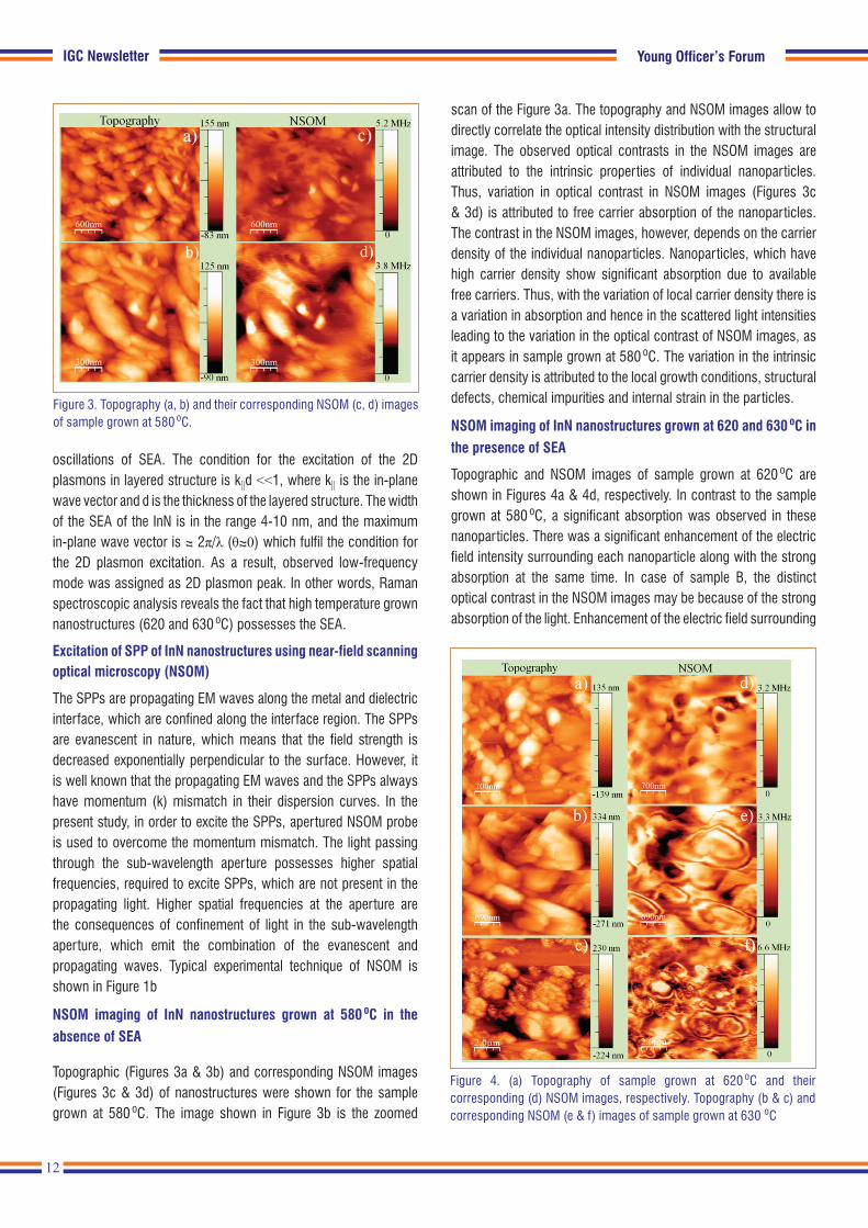
Topographic (Figures 3a & 3b) and corresponding NSOM images (Figures 3c & 3d) of nanostructures were shown for the sample grown at 580 oC. The image shown in Figure 3b is the zoomed
scan of the Figure 3a. The topography and NSOM images allow to directly correlate the optical intensity distribution with the structural image. The observed optical contrasts in the NSOM images are attributed to the intrinsic properties of individual nanoparticles. Thus, variation in optical contrast in NSOM images (Figures 3c & 3d) is attributed to free carrier absorption of the nanoparticles. The contrast in the NSOM images, however, depends on the carrier density of the individual nanoparticles. Nanoparticles, which have high carrier density show significant absorption due to available free carriers. Thus, with the variation of local carrier density there is a variation in absorption and hence in the scattered light intensities leading to the variation in the optical contrast of NSOM images, as it appears in sample grown at 580 oC. The variation in the intrinsic carrier density is attributed to the local growth conditions, structural defects, chemical impurities and internal strain in the particles.
NSOM imaging of InN nanostructures grown at 620 and 630 oC in the presence of SEA
Topographic and NSOM images of sample grown at 620 oC are shown in Figures 4a & 4d, respectively. In contrast to the sample grown at 580 oC, a significant absorption was observed in these nanoparticles. There was a significant enhancement of the electric field intensity surrounding each nanoparticle along with the strong absorption at the same time. In case of sample B, the distinct optical contrast in the NSOM images may be because of the strong absorption of the light. Enhancement of the electric field surrounding
Young Officer’s Forum
Figure 3. Topography (a, b) and their corresponding NSOM (c, d) images of sample grown at 580 oC.
Figure 4. (a) Topography of sample grown at 620 oC and their corresponding (d) NSOM images, respectively. Topography (b & c) and corresponding NSOM (e & f) images of sample grown at 630 oC

13
IGC Newsletter
each nanoparticle is attributed to the resonance kind of behavior of nanoparticles with the availability of sufficient free carrier density originating from the SEA in the system. The plasmonic behavior of these nanoparticles is also confirmed by the Raman spectroscopic analysis (Figure 2e).
Figures 4b & 4e reveal the topography and corresponding NSOM images of the sample C, respectively, scanned at an arbitrary area. Interestingly, there is a striking difference of the NSOM images of sample grown at 630 oC as compared to the other samples. Periodic fringes were observed at each particle in the NSOM images instead of a resonance kind of behaviour. The observed fringes are attributed to the excitation of the propagating SPPs (wavelength, λp). The evanescent field produced by the sub-wavelength aperture excites the SPPs and they propagate towards the edge of the surface where they get reflected. Thus, the observed fringes may be the result of the interference of the excited and back-reflected SPPs. The periodicity of fringe (δ), which is related to the wavelength of SPPs (δ = λp/2), is in the range of 137-250 nm. Thus, the λp is in the range of 274 - 500 nm. The variation in the SPP wavelength for different nanoparticles is attributed to the variation in the carrier density of individual nanoparticles. Origin of the SPPs must be attributed to the 2DEG of the SEA. This is further corroborated by the observed 2D plasmon peak in the Raman spectra (Figures 2e & 2f). Two-dimensional nature of electron gas and very high sheet carrier density are the sole reasons for the observation of the very small SPP wavelengths.
In order to confirm the wave nature of fringes, NSOM imaging is further performed in another area of sample C. The topography and corresponding NSOM images are shown in Figures 4c & 4f, respectively. However, from the topographic images, it is revealed
Young Officer’s Forum
Figure 5. SERS (a) and PL (b) enhancement studies on InN nanostructures grown at 580 oC. SERS (c) and PL (d) enhancement studies on InN nanostructures grown at 650 oC
that nanoparticles are within clustered regions. Interestingly, the NSOM images show interference of fringes between the particles. In essence, the observation of the destructive interference further confirms that the recorded fringes are because of the SPPs generated by the accumulated surface electron of InN and not related to any other phenomena.
SERS activity InN nanostructures
SERS activity of InN nanostructures was explored using the standard SERS analyte such as Rhodamine 6G (R6G) molecules. However, the measurements were performed to study the role of SEA in the SERS activity of InN nanostructures. Hence, two samples were selected for the measurements which were grown at 580 and 650 oC. Among these, high temperature grown sample (650 oC) possesses the SEA. 2D plasmon peak was observed in the Raman spectra of nanostructures grown at and above 620 oC (Figures 2e & 2f). In other words, nanostructures grown at and above 620 oC possess the SEA. Raman spectral intensity of R6G molecules adsorbed on InN nanostructures and bare Al2O3 substrate was compared to probe the SERS activity.
Raman spectra of the R6G molecules adsorbed on the InN nanostructures grown at 580 oC and adsorbed on Al2O3 are shown in Figure 5a. A negligible amount of intensity enhancement was observed in the presence of the InN nanostructures (Figure 5a) as compared to the absence of InN nanostructures (Al2O3 substrate). In addition, the luminescence of the R6G molecules was collected in the presence and absence of the InN nanostructures (Figure 5b). However, enhancement of luminescence intensity was also not observed in the presence of InN nanostructures as compared to the bare substrate.
Raman spectra of the R6G molecules absorbed on the InN nanostructures are grown at 650 oC and Al2O3 substrate are shown in Figure 5c. A considerable amount of intensity enhancement was observed in the presence of InN nanostructures as compared to the absence of InN nanostructures (Al2O3 substrate). The Raman enhancement factor of ~ 1.4x10⁴ is calculated by taking the signals on the Al2O3 substrate as reference. In addition, luminescence from the R6G molecules was also collected in the presence and absence of InN nanostructures (Figure 5d), and the luminescence band intensity was observed to enhance by four times in the presence of nanostructures.
The SERS enhancement is attributed to the excitation of the 2D plasmons of 2DEG corresponding to the SEA of InN nanostructures rather than the LSPR of nanostructures. Thus, InN can be a potential plasmonic material in THz plasmonic region, for which plasmonic properties can be tailored using the variation of carrier density in the SEA. In addition, it is demonstrated that materials InN with SEA can also be used as the semiconductor SERS substrates.
14
IGC Newsletter
in vacuum. The thermal decomposition of sodium hydride releases a large quantity of H2 as the by-product. The released H2 during sodium cleaning and cold trap regeneration will be sampled in inert ambient such as argon or nitrogen. The concentration of H2 has to be monitored to maintain it within the safe level of below 4 % before being let out to the atmosphere. Therefore, both sodium cleaning and cold trap regeneration are in demand of reliable, flow rate independent and accurate H2 sensors which can function in inert ambient. At present, several researchers are taking efforts to develop room temperature H2 sensor operating on change in electrical resistivity, optical constants, potential, current, volume and work function to meet the ever growing demand. Mainly, five types of H2 sensors have been discussed in this report (1) metal oxide sensors, (2) catalytic sensors, (3) thermal conductivity sensors, (4) optical sensors and (5) electrochemical sensors. The above classifications of sensors are based purely on the principle of operation and their characteristics are listed in Table 1.
Table 1 gives the advantages and disadvantages of different types of H2 sensors. Electrochemical sensors are more suitable for monitoring H2 in argon atmosphere than metal oxide and catalytic sensors as these sensors need the presence of O2 in H2 gas stream for detection. Thermal conductivity sensors are highly sensitive to the flow rate change. Interference from ambient light is the issue with optical sensors. Electrochemical sensors comprise both potentiometric and amperometric devices. Unlike potentiometric
Future of this planet largely depends on the successful utilization of molecular hydrogen (H2) as an energy resource in the renewable energy sector. H2 is a clean source of energy with environmentally green combustion products and has the potential to be the lead energy carrier and energy provider. In spite of all these advantages, H2 forms an explosive mixture with air in the concentration range of 4-75% (V/V) resulting in a catastrophic damage. Therefore, to prevent any unforeseen disaster, H2 in the concentration between 0-4 % (Lower Explosion Limit of hydrogen in air) needs to be monitored using suitable sensors. Hence, H2 sensor is high in demand to monitor its leakage wherever H2 is utilized or released as a by product. In fast breeder reactor technology sodium is used as coolant because of its favourable physicochemical properties. The components of the reactor will be removed for the purpose of service/disposal and it will have sodium sticking on the surface. The most adopted processes for sodium removal are steam-nitrogen and water vapour processes depending upon the nature of the component. The reaction of sodium with steam releases a large quantity of H2 which calls for its safe management. H2 sensor also finds application during cold trap regeneration. Cold traps are made up of stainless steel mesh (SS mesh), which are used in sodium cooled fast reactor to maintain the purity of sodium by trapping H2 and O2 as sodium hydrides and sodium oxides and get collected in SS mesh. The cold trap gets saturated with hydride and oxide during the continuous operation of the reactor. Hence, once in five years cold trap needs to be regenerated by thermal decomposition
Young Researcher’s ForumMs. E. Jayanthi is pursuing PhD under HBNI in materials processing chemistry section, MC & MFCG, IGCAR. She received her M.Sc chemistry from Stella Maris College, Chennai. Her research areas includes electrocatalyst, electrodeposition, electrochemical
sensors and fuel cell. She has three peer reviewed journal publications.
Electrodeposition of Platinum on Gas Diffusion Layer for the Application in Proton Exchange Membrane Based
Amperometric H2 Sensor
Young Researcher’s Forum
15
IGC NewsletterYoung Researcher’s Forum
sensors, signal in amperometric sensors varies linearly with respect to H2 concentration, works at room temperature and can operate in wide range of concentration (Table 1) consuming low power with superior sensitivity, selectivity and stability.
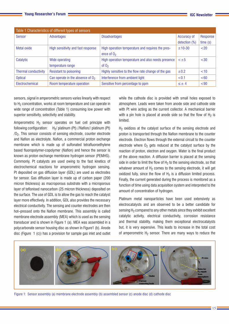
Amperometric H2 sensor operates on fuel cell principle with following configuration: H2/ platinum (Pt) //Nafion// platinum (Pt) /O2. This sensor consists of sensing electrode, counter electrode and Nafion as electrolyte. Nafion, a commercial proton exchange membrane which is made up of sulfonated tetrafluoroethylene based fluoropolymer-copolymer (Nafion) and hence the sensor is known as proton exchange membrane hydrogen sensor (PEMHS). Commonly, Pt catalysts are used owing to the fast kinetics of electrochemical reactions for amperometric hydrogen sensing. Pt deposited on gas diffusion layer (GDL) are used as electrodes for sensor. Gas diffusion layer is made up of carbon paper (200 micron thickness) as macroporous substrate with a microporous layer of teflonised nanocarbon (25 micron thickness) deposited on the surface. The use of GDL is to allow the gas to reach the catalyst layer more effectively. In addition, GDL also provides the necessary electrical conductivity. The sensing and counter electrodes are then hot–pressed onto the Nafion membrane. This assembly is called membrane electrode assembly (MEA) which is used as the sensing transducer and is shown in Figure 1 (a). MEA was assembled in a polycarbonate sensor housing disc as shown in Figure1 (b). Anode disc (Figure 1 (c)) has a provision for sample gas inlet and outlet
while the cathode disc is provided with small holes exposed to atmosphere. Leads were taken from anode side and cathode side with Pt wire acting as the current collector. A mechanical barrier with a pin hole is placed at anode side so that the flow of H2 is limited.
H2 oxidizes at the catalyst surface of the sensing electrode and proton is transported through the Nafion membrane to the counter electrode. Electron flows through the external circuit to the counter electrode where O2 gets reduced at the catalyst surface by the reaction of proton, electron and oxygen. Water is the final product of the above reaction. A diffusion barrier is placed at the sensing side in order to limit the flow of H2 to the sensing electrode, so that whatever amount of H2 comes to the sensing electrode, it will get oxidized fully, since the flow of H2 is a diffusion limited process. Finally, the current generated during the process is monitored as a function of time using data acquisition system and interpreted to the amount of concentration of hydrogen.
Platinum metal nanoparticles have been used extensively as electrocatalysts and are observed to be a better candidate for sensing H2 compared to any other metals since they exhibit excellent catalytic activity, electrical conductivity, corrosion resistance and thermal stability, making them exceptional electrocatalysts but, it is very expensive. This leads to increase in the total cost of amperometric H2 sensor. There are many ways to reduce the
Table 1 Characteristics of different types of sensors
Sensor Advantages Disadvantages Accuracy of
detection (%)
Response
time (s)
Metal oxide High sensitivity and fast response High operation temperature and requires the pres-
ence of O2
±10-30 <20
Catalytic Wide operating
temperature range
High operation temperature and also needs presence
of O2
<±5 <30
Thermal conductivity Resistant to poisoning Highly sensitive to the flow rate change of the gas ±0.2 <10
Optical Can operate in the absence of O2 Interference from ambient light <0.1 <60
Electrochemical Room temperature operation Sensitive from percentage to ppm ≤± 4 <90
Figure 1: Sensor assembly (a) membrane electrode assembly (b) assembled sensor (c) anode disc (d) cathode disc

16
IGC Newsletter Young Researcher’s Forum
cost without sacrificing the performance of H2 sensing and are listed below: reduction of precious metal loading, nanostructured thin-flm development for catalyst layer, particle size reduction for electrocatalyst, developing non-precious metal/alloy and developing novel catalyst preparation methods. We have adopted novel catalyst preparation method for the application in H2 sensor. Commercially adopted methods for Pt catalyst deposition are electrophoretic, brush coating, spray coating and electrodeposition methods. There are advantages and disadvantages with respect to each method. In the case of spray coating/brush coating methods, the active sites are being covered by Nafion which eventually reduce the catalytic sites. Electrophoretic and electrodeposition methods are found to be efficient for deposition of catalyst due to the control of particle size or thickness of the film by potential or time. Electrophoretic method requires high voltage and also their efficiency of deposition depends on the nature of colloidal suspensions. Though electrodeposition method is less efficient compared to electrophoretic, it is economic as well as preparation handy. Hence, platinum on GDL is prepared by electrodeposition method for H2 sensing application and compared with that of brush coated commercial Pt/C catalyst.
Brush coating and electrodeposition of Pt on gas diffusion layer
The catalyst slurry for the cathode was prepared by ultrasonically mixing 10% Pt supported Vulcan XC72R catalyst (E-Tek) with 5 wt. % Nafion, 1:1 ratios of deionized water and 2-propanol was added sequentially to obtain a homogeneous mixture. The catalyst thus prepared was spray-coated onto the GDL and dried in oven at 60°C for 2 h. MEA was prepared by hot pressing the electrodeposited Pt anode and spray coated Pt cathode on either side of pre-cleaned Nafion electrolyte at 120°C under a pressure of 50 bar for a period of 120 s. Electrodeposition of Pt on GDL was carried out in three electrode cells with constant stirring. GDL was used as the working electrode. Platinum sheet and saturated calomel electrode (SCE)
were used as the counter and reference electrodes respectively. Platinum was electrodeposited on GDL at the optimum potential of -0.2 V vs SCE using 3 mM of potassium hexachloro platinate (K2PtCl6) in 0.5 M sulphuric acid (H2SO4) as electrolyte for the duration of 10 min. The loading of Pt on GDL used was 0.5 mg/cm2 and it was calculated by measuring the weight difference before and after the deposition.
Field emission scanning electron microscope (FESEM) images of brush coated Pt on GDL shown in Figure 2 indicate that the particles are connected to each other eventually reducing the catalytic area whereas electrodeposited Pt showed finer distribution of particles. Hence, electrodeposited Pt particles are expected to show better sensing characteristics when compared to brush coated commercial Pt/C catalyst.
Performance evaluation of the sensor
Pristine Ar was passed at the anode side of the sensor to obtain the baseline for sensing H2/Ar mixture. The required concentrations of H2 were passed at anode side using a mass flow controller. Sensor signal leads were connected in series with the current measuring device (Agilent 34972 A data acquisition system/switch unit). The sensor response was recorded with respect to various concentrations of H2 ranging from 1% to 5% (V/V). The sensor was tested for repeatability. Response time of the sensor was calculated at 90 % saturation of the sensor signal. Sensitivity of the sensor was obtained from the slope of the calibration plot of sensor signal vs concentration of H2.
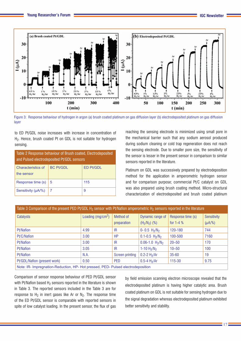
Sensor response to 0.5 % - 4 % H2/Ar for sensors with brush coated Pt on GDL (BC Pt/GDL) and electrodeposited Pt on GDL (ED Pt/GDL) are shown in Figure 3. Sensitivity and response time of BC Pt/GDL and ED Pt/GDL are shown in Table 2. The sensitivity of ED Pt/GDL sensor is found to be better than BC Pt/GDL sensor. Even though the response time is less in BC Pt/GDL sensor compared
Figure 2: FESEM images of (a) blank GDL (b) brush coated Pt/C catalyst on GDL (c) electrodeposited Pt on GDL
17
IGC NewsletterYoung Researcher’s Forum
Figure 3: Response behaviour of hydrogen in argon (a) brush coated platinum on gas diffusion layer (b) electrodeposited platinum on gas diffusion layer
to ED Pt/GDL noise increases with increase in concentration of H2. Hence, brush coated Pt on GDL is not suitable for hydrogen sensing.
Table 2 Response behaviour of Brush coated, Electrodeposited
and Pulsed electrodeposited Pt/GDL sensors
Characteristics of the sensor
BC Pt/GDL ED Pt/GDL
Response time (s) 5 115
Sensitivity (μA/%) 7 9
reaching the sensing electrode is minimized using small pore in the mechanical barrier such that any sodium aerosol produced during sodium cleaning or cold trap regeneration does not reach the sensing electrode. Due to smaller pore size, the sensitivity of the sensor is lesser in the present sensor in comparison to similar sensors reported in the literature.
Platinum on GDL was successively prepared by electrodeposition method for the application in amperometric hydrogen sensor and for comparison purpose; commercial Pt/C catalyst on GDL was also prepared using brush coating method. Micro-structural characterization of electrodeposited and brush coated platinum
Table 3 Comparison of the present PED Pt/GDL H2 sensor with Pt/Nafion amperometric H2 sensors reported in the literature
Catalysts Loading (mg/cm2) Method of
preparation
Dynamic range of
(H2/N2) (%)
Response time (s)
for 1-4 %
Sensitivity
(µA/%)
Pt/Nafion 4.99 IR 0- 0.5 H2/N2 120-180 744
Pt/C/Nafion 3.00 HP 0.1-0.5 H2/N2 100-500 7160
Pt/Nafion 3.00 IR 0.06-1.0 H2/N2 20–50 170
Pt/Nafion 3.05 IR 1-10 H2/N2 10–50 100
Pt/Nafion N.A. Screen printing 0.2-2 H2/Ar 35-60 19
Pt/GDL/Nafion (present work) 0.50 PED 0.5-4 H2/Ar 115-30 9.75
Note: IR- Impregnation-Reduction, HP- Hot pressed, PED- Pulsed electrodeposition
Comparison of sensor response behaviour of PED Pt/GDL sensor with Pt/Nafion based H2 sensors reported in the literature is shown in Table 3. The reported sensors included in the Table 3 are for response to H2 in inert gases like Ar or N2. The response time of the ED Pt/GDL sensor is comparable with reported sensors in spite of low catalyst loading. In the present sensor, the flux of gas
by field emission scanning electron microscope revealed that the
electrodeposited platinum is having higher catalytic area. Brush
coated platinum on GDL is not suitable for sensing hydrogen due to
the signal degradation whereas electrodeposited platinum exhibited
better sensitivity and stability.
18
IGC Newsletter Conference and Meeting Highlights
Conference and Meeting Highlights
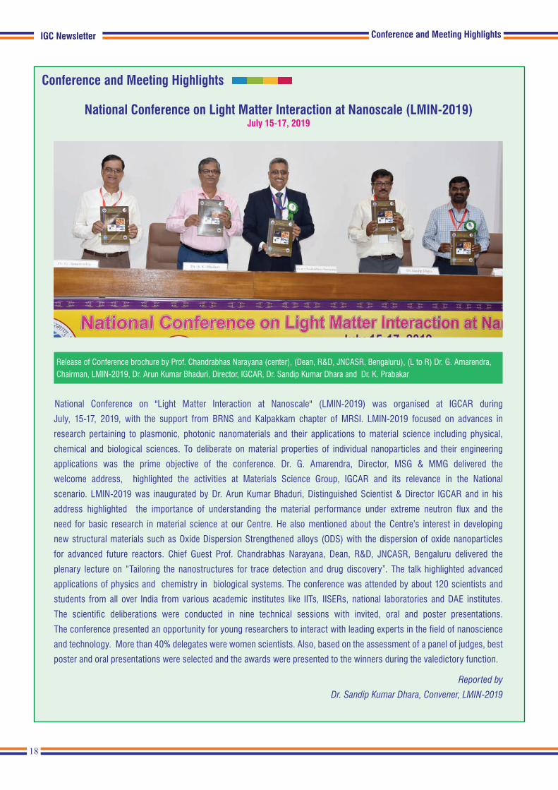
Release of Conference brochure by Prof. Chandrabhas Narayana (center), (Dean, R&D, JNCASR, Bengaluru), (L to R) Dr. G. Amarendra, Chairman, LMIN-2019, Dr. Arun Kumar Bhaduri, Director, IGCAR, Dr. Sandip Kumar Dhara and Dr. K. Prabakar
National Conference on Light Matter Interaction at Nanoscale (LMIN-2019)July 15-17, 2019
National Conference on "Light Matter Interaction at Nanoscale" (LMIN-2019) was organised at IGCAR during
July, 15-17, 2019, with the support from BRNS and Kalpakkam chapter of MRSI. LMIN-2019 focused on advances in
research pertaining to plasmonic, photonic nanomaterials and their applications to material science including physical,
chemical and biological sciences. To deliberate on material properties of individual nanoparticles and their engineering
applications was the prime objective of the conference. Dr. G. Amarendra, Director, MSG & MMG delivered the
welcome address, highlighted the activities at Materials Science Group, IGCAR and its relevance in the National
scenario. LMIN-2019 was inaugurated by Dr. Arun Kumar Bhaduri, Distinguished Scientist & Director IGCAR and in his
address highlighted the importance of understanding the material performance under extreme neutron flux and the
need for basic research in material science at our Centre. He also mentioned about the Centre’s interest in developing
new structural materials such as Oxide Dispersion Strengthened alloys (ODS) with the dispersion of oxide nanoparticles
for advanced future reactors. Chief Guest Prof. Chandrabhas Narayana, Dean, R&D, JNCASR, Bengaluru delivered the
plenary lecture on “Tailoring the nanostructures for trace detection and drug discovery”. The talk highlighted advanced
applications of physics and chemistry in biological systems. The conference was attended by about 120 scientists and
students from all over India from various academic institutes like IITs, IISERs, national laboratories and DAE institutes.
The scientific deliberations were conducted in nine technical sessions with invited, oral and poster presentations.
The conference presented an opportunity for young researchers to interact with leading experts in the field of nanoscience
and technology. More than 40% delegates were women scientists. Also, based on the assessment of a panel of judges, best
poster and oral presentations were selected and the awards were presented to the winners during the valedictory function.
Reported by
Dr. Sandip Kumar Dhara, Convener, LMIN-2019

19
IGC Newsletter
Conference and Meeting Highlights
National Technology Day Meet 2019July 30, 2019
As a part of National Technology Day celebration, a seminar cum exhibition was conducted at IGCAR on July 30, 2019 for the
non-gazetted staff (technical/administration/accounts/stores) of the DAE Units at Kalpakkam. The objective of this event was
to highlight the important, innovative and novel contributions made by the staff towards the various projects and programmes
of the Centre. It was conducted as a trilingual event (English, Hindi and Tamil) with the participants presenting and showcasing
their works/achievements in the past two years. The seminar comprised of both oral and poster sessions. An exhibition
was also arranged wherein the components / products / gadgets / devices / systems / models / concepts developed by the
individuals / groups were displayed.
The meet was held in parallel sessions with wide participation of employees from IGCAR, MAPS, BHAVINI, BARC(F), SRI and
GSO. Totally 167 papers were presented which included 60 oral and 94 poster presentations with remaining as exhibits. Apart
from the 225 presenting authors 40 staff members who superannuated from service during July 1, 2019 to May 31, 2020 also
participated in this event.
Shri V. Balamurugan, Outstanding Scientist & Director Combat Vehicles Research and Development Establishment (CVRDE)
Chennai, was the Chief Guest. He made a lucid presentation on the development of Arjun Main Battle Tanks for Indian army.
Panels of juries evaluated the oral, poster and exhibit presentations. Certificates for best papers / posters / exhibits were
distributed by Dr. Arun Kumar Bhaduri, Distinguished Scientist & Director, IGCAR during the valedictory function.
Reported by
K. Velusamy, Convener, National Technology Day Meet 2019
Conference and Meeting Highlights
Dr. P. Selvaraj, the then Director FRTG, Dr. Arun Kumar Bhaduri, Director, IGCAR, Shri V. Balamurugan, Director, CVRDE, Dr. K. Velusamy, Convener of the meet during the release of Technology Day brochure

20
IGC Newsletter Training Programmes and Courses
Training Programmes and Courses
Summer training in physics and chemistry (STIPAC) is a prestigious flagship programme conducted by IGCAR every year
since 1995, for M.Sc. first year students. This program is intended to motivate, enthuse and encourage young students to
take up scientific research as a career. STIPAC has evolved over the years to train the pre-final PG Physics & Chemistry
students from across the country both in theoretical & experimental expertise available in IGCAR.
Theme chosen for this year’s programme was “Physics and Chemistry of Nanomaterials” and students were asked to submit
a one page write up about their perspective on the above theme. Applications were invited online and about 650 applications
were received from Physics and Chemistry, representing about 100 universities across the country. Based on their academic
credentials, quality of their write-up, twenty five students in each discipline were selected.
The STIPAC-19 programme was inaugurated on June 06, 2019 and Dr. Arun Kumar Bhaduri, Distinguished Scientist &
Director, IGCAR graced the event and gave a special lecture on “Fast Breeder Reactor & Associated Fuel Cycle for the Second
Stage of Indian Nuclear Programme”.
The program was conducted for six weeks consisting of about 100 hours of lectures in theory and 50 hours of experiments.
The students were encouraged to have hands-on learning experience by either doing project works or carrying out experimental
works on various topics. Towards the end of the course, the students gave a presentation on the project work carried out,
which was evaluated by senior Scientists of the Centre. Site visits to MAPS and BHAVINI were also organized during the
Chief Guests Dr. Arun Kumar Bhaduri, Director, IGCAR and Prof. P. Appa Rao, Vice Chancellor, University of Hyderabad
addressing STIPAC students during inaugural and valedictory functions, respectively
Summer Training in Physics & Chemistry (STIPAC-2019)June 03 - July 12, 2019
21
IGC NewsletterTraining Programmes and Courses
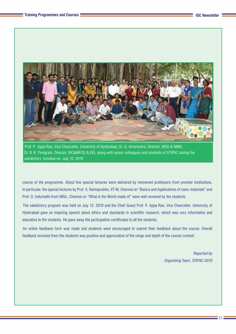
Prof. P. Appa Rao, Vice Chancellor, University of Hyderabad, Dr. G. Amarendra, Director, MSG & MMG,
Dr. B. K. Panigrahi, Director, MC&MFCG & EIG, along with senior colleagues and students of STIPAC during the
valedictory function on July 12, 2019
course of the programme. About five special lectures were delivered by renowned professors from premier institutions.
In particular, the special lectures by Prof. S. Ramaprabhu, IIT-M, Chennai on “Basics and Applications of nano-materials” and
Prof. D. Indumathi from IMSc, Chennai on “What is the World made of” were well received by the students.
The valedictory program was held on July 12, 2019 and the Chief Guest Prof. P. Appa Rao, Vice Chancellor, University of
Hyderabad gave an inspiring speech about ethics and standards in scientific research, which was very informative and
educative to the students. He gave away the participation certificates to all the students.
An online feedback form was made and students were encouraged to submit their feedback about the course. Overall
feedback received from the students was positive and appreciative of the range and depth of the course content.
Reported by
Organising Team, STIPAC-2019

22
IGC Newsletter
Training Programmes and Courses
Fifty students from BITS Pilani, Hyderabad and Goa Campuses underwent summer practice school at IGCAR during
May 21 to July 13, 2019. The programme is aimed at exposing the students to industrial and research environment, how the
organizations work, maintaining work ethics, and completing the projects given to them in time by effectively making use
of the guidance, scientific information resources, hard work and creativity. Dr. Arun Kumar Bhaduri, Distinguished Scientist
and Director, IGCAR inaugurated the practice school programme and interacted with the students. Dr. Satyapaul Singh from
Hyderabad campus was the program coordinator from BITS. The students were from various disciplines like Mechanical
Engineering, Chemical Engineering, Civil Engineering, Electrical and Electronics Engineering, Electronics & Instrumentation
Engineering, Electronics and Communication Engineering, Computer Science and Engineering and Manufacturing Technology.
They carried out challenging projects in various groups of the Centre according to their discipline under the able guidance of
Scientists and Engineers at IGCAR. During the period of their stay, they visited facilities at IGCAR, BHAVINI and MAPS. As
a part of the curriculum, quiz, project work presentations, group discussions, report writing and viva were conducted. The
valedictory function was held on July 13, 2019. Dr. B. Venkatraman, Director, SQRMG and ESG delivered the valedictory
address and gave away the certificates to the students.
Reported by
Organising Team, BITS-Practice School
BITS Summer Practice School at IGCARMay 21 - July 13, 2019
Students from BITS Practice School with Dr. B. Venkatraman, Director, SQRMG & ESG and senior colleagues of the Centre
Training Programmes and Courses

23
IGC NewsletterTraining Programmes and Courses
First Bridge Course on ‘Welding and Fabrication’ was organised during July 22-26, 2019 at IGCAR, Kalpakkam for the
benefit of students completing first year M.E/M.Tech. This was jointly organised by the Indian Institute of Welding (IIW),
Chennai branch, American Welding Society, India International Section & Indira Gandhi Centre for Atomic Research (IGCAR),
Kalpakkam.
A total of 25 students from Institutes across the country such as IIT Kanpur, NIT’s, PSG college of technology, MS university
of Baroda, GEC Thrissur, Engineering colleges in Tamil Nadu & neighboring states participated in the course.
The course was inaugurated by Shri T. Johny, Associate Director, TSG/ESG, IGCAR, in the presence of Dr. M. V. Venkatesan,
Chairman IIW-INDIA Chennai Branch and Shri Shyam Baskaran, General Secretary, AWS INDIA International Section.
The valedictory function was chaired by Dr. Arun Kumar Bhaduri, Director IGCAR & President, IIW-INDIA. Prizes were given
to three students who topped the evaluation conducted for them. The course convener was Dr. Shaju K Albert, Associate
Director, MEG/MMG and was coordinated by Shri T. V. Prabhu, Shri R. Ravikumar and their colleagues.
Reported by
Shri T.V. Prabhu and colleagues
Dr. Arun Kumar Bhaduri, Director, IGCAR along with senior colleagues of the Centre and participants of the course
Bridge Course on ‘Welding and Fabrication’ July 22-26, 2019
Training Programmes and Courses

24
IGC Newsletter Training Programmes and Courses
Level-2 certification course on Eddy Current Testing as per IS 13805 was conducted by IGCAR in association with ISNT
Kalpakkam chapter during August 19-23, 2019 at IGCAR. Certification examination was conducted by National Certification
Board (NCB) of ISNT on August 24, 2019. Dr. C. K. Mukhopadhyay, Head, NDE Division/MMG served as the Course Director.
The course was inaugurated by Dr. Shaju K. Albert, Associate Director, MEG/MMG. A special address was given by
Dr. B. P. C. Rao, Project Director, FRFCF and Chairman, ISNT Kalpakkam Chapter during the inaugural session. The course
was attended by nineteen participants from different organisations including IGCAR, NPCIL, BHAVINI and Heavy Water
Plants. Eminent faculty like Shri Arbind Kumar, QAD, BARC, Mumbai and Shri T. S. V. R. Nageswara Rao, M-QAT, NFC,
Hyderabad delivered lectures in the course. Fourteen candidates have successfully passed the examination conducted
by NCB and certificates were issued to them.
Reported by
Dr. C. K. Mukhopadhyay
Head, NDED, MMG
Participants of the course along with senior colleagues of the Centre
Eddy current Level-2 certification courseAugust 19-24, 2019
Training Programmes and Courses

25
IGC Newsletter
Twenty three Trainee Scientific Officers from the 13th batch of BARC Training School at IGCAR have successfully completed
their training and were graduated in a special ceremony that took place on July 29, 2019. Shri S.A. Bhardwaj, Former
Chairman, Atomic Energy Regulatory Board (AERB) Mumbai was the Chief Guest for the function. Dr. B. Venkatraman,
Director, SQ&RMG & ESG, welcomed the gathering. Dr. Vidya Sundararajan, Head, P&HRMD briefed the audience about
Orientation Course in Engineering and Sciences disciplines. Dr. Arun Kumar Bhaduri, Distinguished Scientist and Director,
IGCAR delivered the presidential address. Shri S. A. Bhardwaj released the souvenir featuring the activities of the training
school programme in the previous academic year. He also gave away the prestigious ‘Homi Bhabha Prizes' comprising of
a medallion and books worth Rs.5000 to the toppers from each discipline and addressed the gathering. He also gave away
the course completion certificates to all the graduates passing out. A few of the Trainee Scientific Officers passing out
shared their experience, gave feedback on the academic programme and their stay at the hostel. Shri S. A. Bhardwaj gave
a very inspiring and enlightening lecture to the gathering. Dr. N. Madurai Meenachi, Head, OCES-Training Section, Resource
Management Group, proposed the vote of thanks.
Reported by Dr. N. Madurai Meenachi, Head, OCES
Release of souvenir at the graduation function. Dr. B. Venkatraman, Director, SQRMG & ESG, Dr. Arun Kumar Bhaduri, Director, IGCAR, Shri S. A. Bhardwaj, Former Chairman, AERB, Mumbai, Dr. Vidya Sundararajan, Head, P&HRMD and Dr. N. Madurai Meenachi, Head, OCES-Training Section, RMG
Graduation Function of the 13th Batch of Trainee Scientific Officers of BARC Training School at IGCAR
July 29, 2019
News and Events
Graduates of BARC Training School at IGCAR with Shri S. A. Bhardwaj, Former Chairman, AERB, Mumbai, Dr. Arun Kumar Bhaduri, Director, IGCAR and senior colleagues of the Centre
News and Events

26
IGC Newsletter
March for Science is a worldwide movement to spread the scientific temper and to urge greater priority for science education
and research. Starting from 2017, every year science programmes and rallies are organised. Many prominent scientists have
been participating in these events world over and across India. As part of this, a special Colloquium was organised by IGCAR
in association with Tamil Nadu Science Forum (TNSF) on September 03, 2019 at IGCAR. Dr R. Ramanujam and Dr. M. V. N.
Murthy, Institute of Mathematical Sciences, Chennai delivered lectures respectively on the topics “Let us March for Science"
and "Science Needs Funding”. The lectures highlighted the genesis of this global initiative and the need for such a movement.
Dr. Arun Kumar Bhaduri, Distinguished Scientist & Director, IGCAR, gave a special address to the audience. At the end there
was an interaction session with the speakers and the audience.
As part of this programme, a rally was organised in the Kalpakkam Township in the evening to spread the Scientific
temper amongst public. Volunteers from
Tamil Nadu Science Forum, Research
Scholars of HBNI-IGCAR and common public
participated in the rally. At the culmination
point, a brief meeting was organised and
Dr. B. Venkatraman, Director SQRMG and ESG
gave a special address to the participants of the
rally.
Reported by
Dr. T. S. Lakshmi Narasimhan and
Shri R. Mathiyarasu,
SQ&RMG
Dr. Arun Kumar Bhaduri, Director, IGCAR addressing the audience
Special Colloquium on March for Science September 03, 2019
News and Events
News and Events
Participants of evening rally
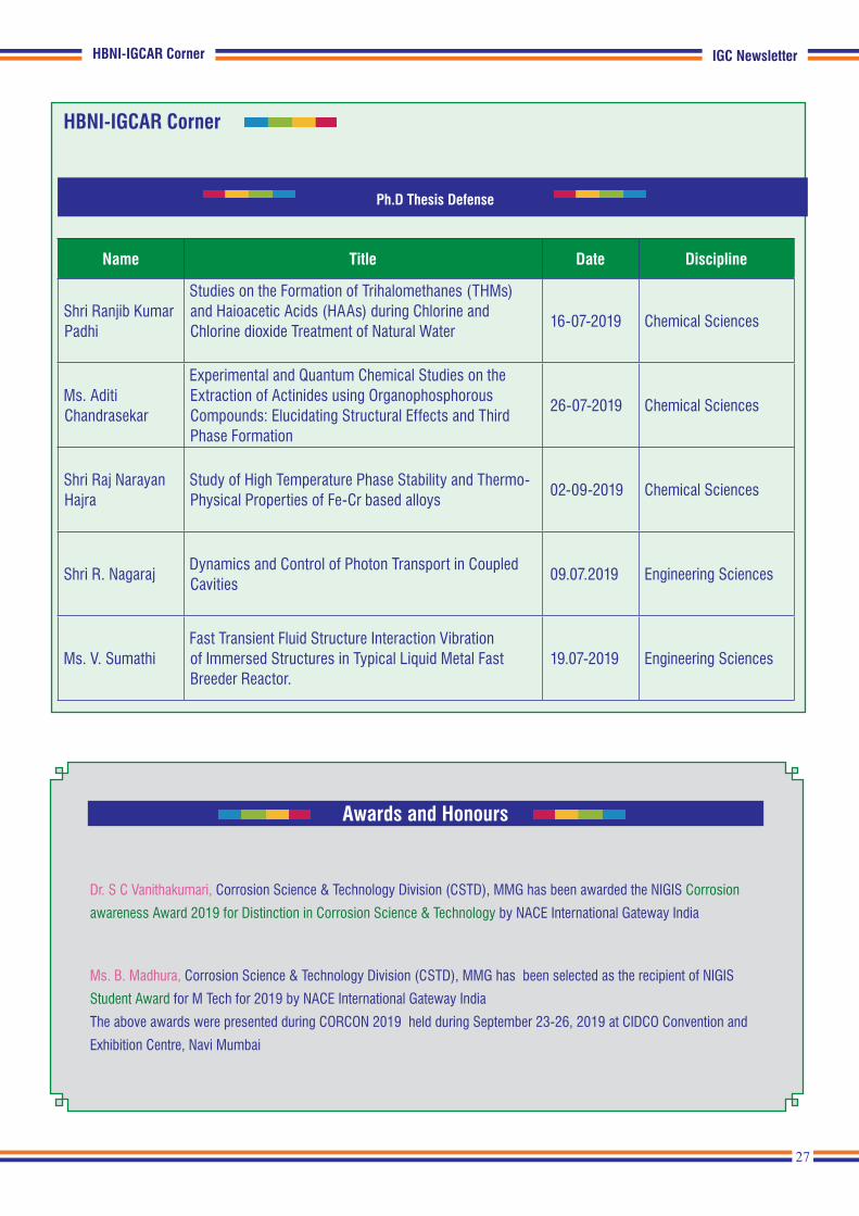
27
IGC Newsletter
Ph.D Thesis Defense
Name Title Date Discipline
Shri Ranjib Kumar Padhi
Studies on the Formation of Trihalomethanes (THMs) and Haioacetic Acids (HAAs) during Chlorine and Chlorine dioxide Treatment of Natural Water
16-07-2019 Chemical Sciences
Ms. Aditi Chandrasekar
Experimental and Quantum Chemical Studies on the Extraction of Actinides using Organophosphorous Compounds: Elucidating Structural Effects and Third Phase Formation
26-07-2019 Chemical Sciences
Shri Raj Narayan Hajra
Study of High Temperature Phase Stability and Thermo-Physical Properties of Fe-Cr based alloys
02-09-2019 Chemical Sciences
Shri R. Nagaraj Dynamics and Control of Photon Transport in Coupled Cavities
09.07.2019 Engineering Sciences
Ms. V. SumathiFast Transient Fluid Structure Interaction Vibration of Immersed Structures in Typical Liquid Metal Fast Breeder Reactor.
19.07-2019 Engineering Sciences
HBNI-IGCAR Corner
HBNI-IGCAR Corner
Awards and Honours
Dr. S C Vanithakumari, Corrosion Science & Technology Division (CSTD), MMG has been awarded the NIGIS Corrosion
awareness Award 2019 for Distinction in Corrosion Science & Technology by NACE International Gateway India
Ms. B. Madhura, Corrosion Science & Technology Division (CSTD), MMG has been selected as the recipient of NIGIS
Student Award for M Tech for 2019 by NACE International Gateway India
The above awards were presented during CORCON 2019 held during September 23-26, 2019 at CIDCO Convention and
Exhibition Centre, Navi Mumbai
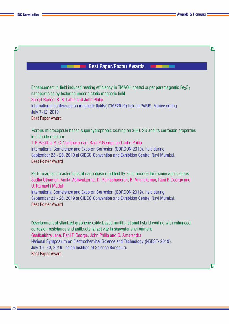
28
IGC Newsletter Awards & Honours
Enhancement in field induced heating efficiency in TMAOH coated super paramagnetic Fe3O4 nanoparticles by texturing under a static magnetic field Surojit Ranoo, B. B. Lahiri and John PhilipInternational conference on magnetic fluids( ICMF2019) held in PARIS, France during July 7-12, 2019 Best Paper Award
Porous microcapsule based superhydrophobic coating on 304L SS and its corrosion properties in chloride medium T. P. Rasitha, S. C. Vanithakumari, Rani P. George and John PhilipInternational Conference and Expo on Corrosion (CORCON 2019), held during September 23 - 26, 2019 at CIDCO Convention and Exhibition Centre, Navi Mumbai. Best Poster Award
Performance characteristics of nanophase modified fly ash concrete for marine applications Sudha Uthaman, Vinita Vishwakarma, D. Ramachandran, B. Anandkumar, Rani P. George and U. Kamachi MudaliInternational Conference and Expo on Corrosion (CORCON 2019), held during September 23 - 26, 2019 at CIDCO Convention and Exhibition Centre, Navi Mumbai. Best Poster Award
Development of silanized graphene oxide based multifunctional hybrid coating with enhanced corrosion resistance and antibacterial activity in seawater environment Geetisubhra Jena, Rani P. George, John Philip and G. AmarendraNational Symposium on Electrochemical Science and Technology (NSEST- 2019), July 19 -20, 2019, Indian Institute of Science BengaluruBest Paper Award
Best Paper/Poster Awards
Awards & Honours IGC Newsletter
Best Paper/Poster Awards
Corrosion Kinetics Study of 316N Weldment Under Cyclic Loading in Acidified Chloride Environment A. Poonguzhali, S. Ningshen and G. AmarendraInternational Conference on Advances in Minerals, Metals, Materials, Manufacturing and Modelling (ICAM-2019) held during September 25 - 27, 2019 at NIT, Warangal Best Paper Award
Numerical Simulation of Fluid flow and Weld Penetration during A-TIG Welding of 316 LN SS Anoop K. Unni and M. VasudevanInternational Conference on Materials and Manufacturing Methods, NIT Trichy, July 5-8, 2019 Best Paper Award
Numerical Simulation and Experimental Validation of A-TIG Welding of 2.25Cr-1Mo Steel A. R. Pavan, B. Arivazhagan, S. Arunkumar, M. Vasudevan and S. MahadevanInternational Conference on Computational Methods in Manufacturing, March 8-9, 2019, IIT Guwahati. Best Paper Award
Aerosol penetration in submerged gravel bed scrubber Arjun Pradeep, Anil Kumar Sharma, D. Ponraju, B. K. Nashine, and P. Selvaraj7th Asian Symposium on Computational Heat Transfer and Fluid Flow - 2019, September 3-7, 2019,Tokyo, Japan Best Paper Award

Editorial Committee Members: Dr. T. S. Lakshmi Narasimhan, Dr. N. V. Chandra Shekar, Dr. C. K. Mukhopadhyay, Dr. Vidya Sundararajan, Shri A. Suriyanarayanan, Dr. C. V. S. Brahmananda Rao, Dr. V. Subramanian, Ms. R. Preetha, Shri J. Kodandaraman,
Shri G. Venkat Kishore, Shri S. Kishore, Dr. N. Desigan, Shri M. Rajendra Kumar, Ms. S. Rajeswari, Shri K. Ganesan, Shri K. Varathan and Shri G. Pentaiah
Published by Scientific Information Resource Division, RMG, SQ&RMG, IGCAR, Kalpakkam-603102
Common Kingfisher is a small bird and one of the most common birds in Kalpakkam backwaters. Male and female are almost identical except that in the case of female, there will be an orange coloration with a black tip on the lower part of the mandible.
Biodiversity Basket - Avian Fauna
Common Kingfisher