igcse physics notes
TRANSCRIPT

Physicsfor the
Cambridge iGCSE Syllabus
B. Murphy


Contents
Topic Page Number
Topic 1 General Physics 2 Past Paper Questions 26Topic 2 Thermal Physics 70 Past Paper Questions 83Topic 3 Waves 108 Past Paper Questions 120Topic 4 Electricity & Magnetism 146 Past Paper Questions 173Topic 5 Atomic Physics 214 Past Paper Questions 221
AppendixSyllabus 234
1

Topic 1:General Physics
Length• Length is a distance measurement and its SI unit is
the metre (m).
• Length is usually measured with a rule, a tape or a trundle wheel.
• Small lengths are measured with a micrometer or callipers where a greater precision is available.
• In certain circumstances, average lengths can be found be measuring a number of distances together then dividing by the number of objects eg a ream of paper.
Time• Time is usually measured with a stopclock. Human
timing is not precise because of reaction times.
• The SI unit for time is seconds (s).
• For repeated events, an average time can be found by measuring a number of repeats then dividing by the number of cycles eg. a pendulum.
1
2
3
2
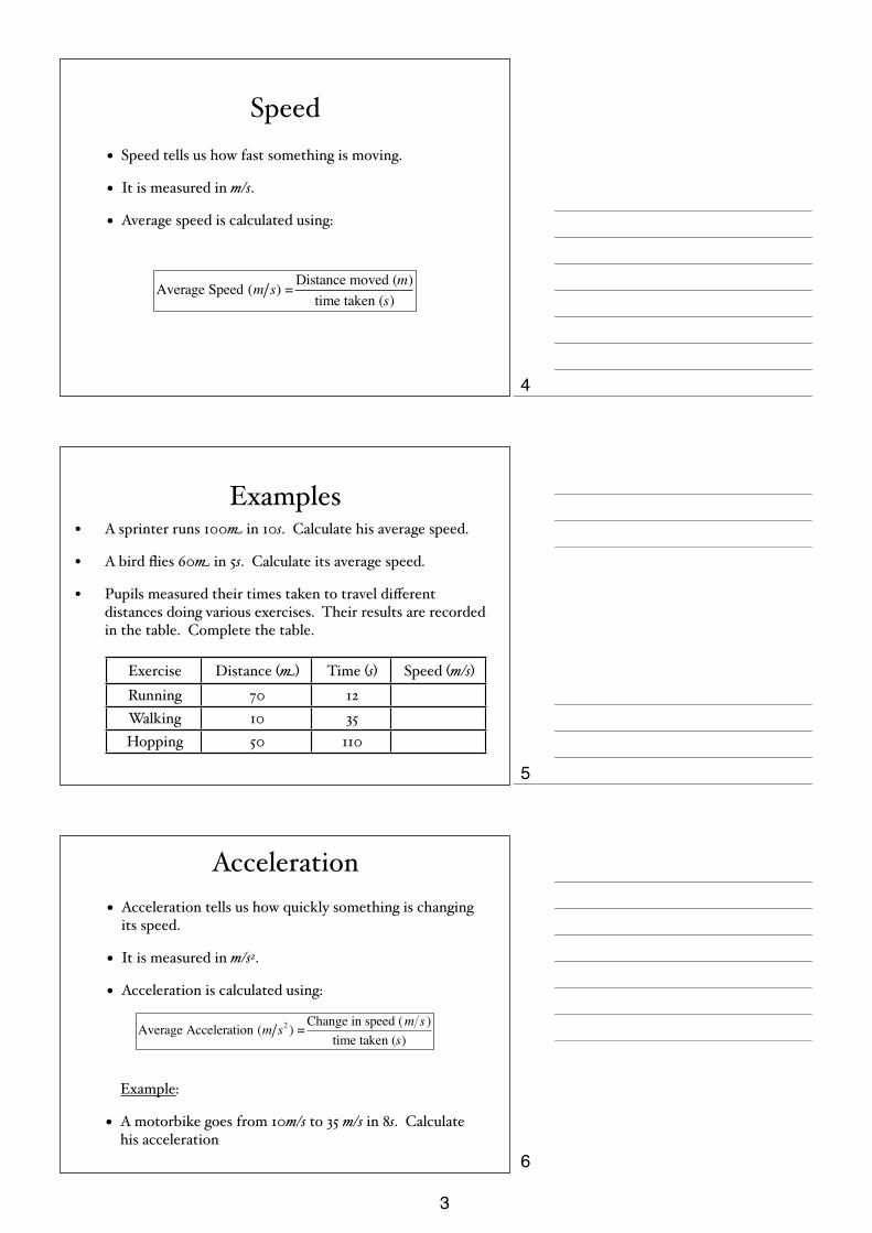
Speed• Speed tells us how fast something is moving.
• It is measured in m/s.
• Average speed is calculated using:
Average Speed (m s) = Distance moved (m)time taken (s)
Examples• A sprinter runs 100m in 10s. Calculate his average speed.
• A bird flies 60m in 5s. Calculate its average speed.
• Pupils measured their times taken to travel different distances doing various exercises. Their results are recorded in the table. Complete the table.
Exercise Distance (m) Time (s) Speed (m/s)Running 70 12Walking 10 35Hopping 50 110
Acceleration• Acceleration tells us how quickly something is changing
its speed.
• It is measured in m/s2.
• Acceleration is calculated using:
Average Acceleration (m s2 ) = Change in speed (m s )time taken (s)
Example:
• A motorbike goes from 10m/s to 35 m/s in 8s. Calculate his acceleration
4
5
6
3
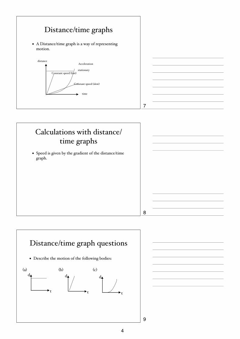
Distance/time graphs
• A Distance/time graph is a way of representing motion.
time
distance
stationaryConstant speed (fast)
Constant speed (slow)
Acceleration
Calculations with distance/time graphs
• Speed is given by the gradient of the distance/time graph.
Distance/time graph questions
• Describe the motion of the following bodies:
t
d(a)
t
d(b)
t
d
(c)
7
8
9
4

Distance/Time Graph questions
• Calculate the speeds of the car and the bike below:
CarBike
0
125
250
375
500
0 5 10 15 20 25
Dis
tanc
e (m
)
Time (s)
Speed/time graphs• A Speed/time graph is an alternative way
of representing motion.
time
speed
Constant speedRapid acceleration
Gradual acceleration
Non-Uniform Acceleration
Stationary
Calculations with speed/time graphs
• Acceleration is given by the gradient of the speed/time graph.
• Distance is given by the Area under the speed/time graph.
10
11
12
5

Speed/time graph questions
• Describe the motion of the following bodies:
t
v(a)
t
v(b)
t
v
(c)
Speed/time calculation.• (a) Find the acceleration of the bike in the first 10s.
• (b) Find the distance moved by the bike in the first 20s.
0
3.75
7.50
11.25
15.00
0 5 10 15 20
Motion of a bike
Spee
d (m
/s)
time (s)
The Ticker-Timer
• The ticker-timer runs at 50Hz. It puts 50 dots on the tape every second.
• If the tape moves quickly, the dots are widely spaced.
• If the tape moves slowly, the dots are close
Ticker Timer
Ticker Tape
13
14
15
6
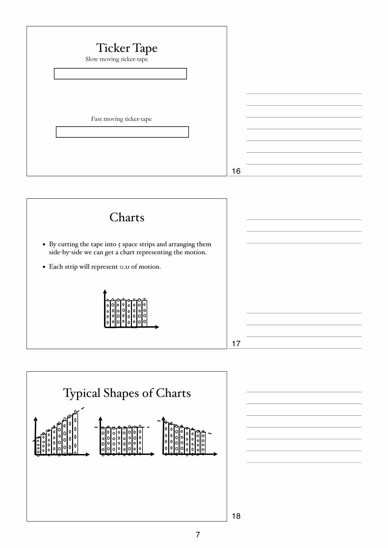
Ticker TapeSlow moving ticker-tape
Fast moving ticker-tape
Charts
• By cutting the tape into 5 space strips and arranging them side-by-side we can get a chart representing the motion.
• Each strip will represent 0.1s of motion.
Typical Shapes of Charts
16
17
18
7
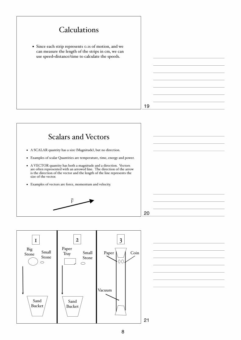
Calculations
• Since each strip represents 0.1s of motion, and we can measure the length of the strips in cm, we can use speed=distance/time to calculate the speeds.
Scalars and Vectors• A SCALAR quantity has a size (Magnitude), but no direction.
• Examples of scalar Quantities are temperature, time, energy and power.
• A VECTOR quantity has both a magnitude and a direction. Vectors are often represented with an arrowed line. The direction of the arrow is the direction of the vector and the length of the line represents the size of the vector.
• Examples of vectors are force, momentum and velocity.
F
Big Stone
Sand Bucket
Small Stone
1
Small Stone
Paper Tray
Sand Bucket
2
Vacuum
Paper Coin
3
19
20
21
8

Gravity• Experiment 1
• Both Stones Land at the same time.
• Gravity makes them fall at the same rate.
• Experiment 2
• Stone landed first.
• Air Resistance slowed down the paper tray.
• Experiment 3
• Both coin & paper land at the same time.
Weight and Mass• Weight is a force. It tells us how heavy something
is. It is measured in newtons (N). It changes depending upon the size of gravity. (Trip to the moon)
• Mass tells us how much substance there is in an object. It is measured in kilograms (kg). It never changes.
• On Earth we multiply mass by 10 to get weight.
Density• Density tells us how compact the mass is in a material.
• It is given by:
or
•Stick to one set of units.
•Water has a density of 1000 kg/m3 or 1 g/cm3.
•Materials with a smaller density than water will float, materials with a higher density than water will sink.
Density (kg m3) = mass(kg)volume(m3)
Density (g cm3) = mass(g)volume(cm3)
22
23
24
9

Density CalculationComplete the following table:
Object Density (kg/m3) Mass (kg) Volume (m3)
A 4000 2
B 8000 4
C 2000 1000
D 2000 4
a) Which object has the greatest mass?
b) Which has the smallest volume?
c) Which objects could be made of the same substance?
d) Which object would float on water?
Irregular objects• The volume of a liquid can be determined using a
measuring cylinder.
• The volume of irregular objects has to be found by displacement.
Hooke’s Law• Hooke’s Law states that the extension in a spring is
proportional to the load applied.
The constant of proportionality is called the Spring Constant.
load α extensionor
F = kx
25
26
27
10
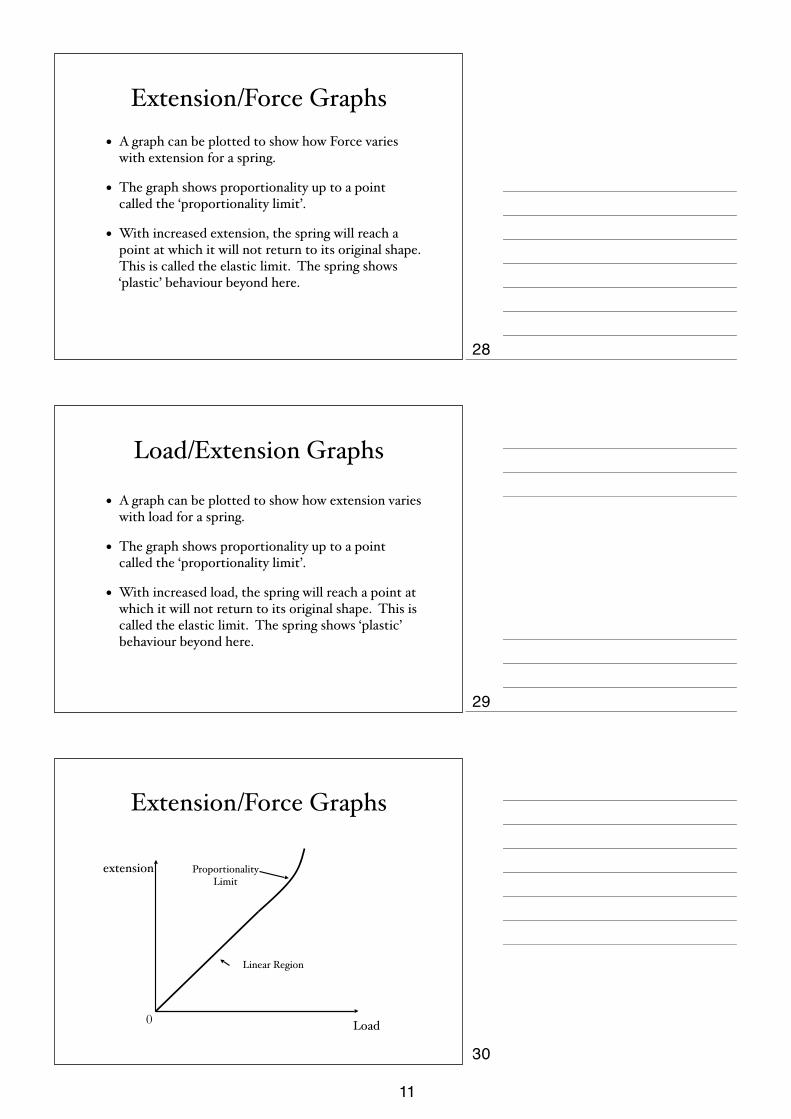
Extension/Force Graphs• A graph can be plotted to show how Force varies
with extension for a spring.
• The graph shows proportionality up to a point called the ‘proportionality limit’.
• With increased extension, the spring will reach a point at which it will not return to its original shape. This is called the elastic limit. The spring shows ‘plastic’ behaviour beyond here.
Load/Extension Graphs
• A graph can be plotted to show how extension varies with load for a spring.
• The graph shows proportionality up to a point called the ‘proportionality limit’.
• With increased load, the spring will reach a point at which it will not return to its original shape. This is called the elastic limit. The spring shows ‘plastic’ behaviour beyond here.
Extension/Force Graphs
extension
Load0
Proportionality Limit
Linear Region
28
29
30
11
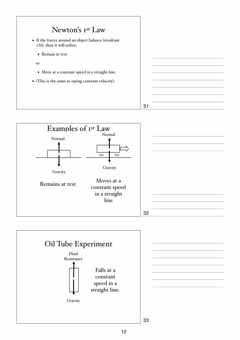
Newton’s 1st Law• If the forces around an object balance (resultant
0N), then it will either:
• Remain at rest
or
• Move at a constant speed in a straight line.
• (This is the same as saying constant velocity).
Examples of 1st Law
Remains at rest Moves at a constant speed
in a straight line
Normal
Air Air
Gravity
Normal
Gravity
Oil Tube Experiment
Gravity
Fluid Resistance
Falls at a constant
speed in a straight line.
31
32
33
12

Unbalanced Forces• If the forces around an object do not balance, then
they will cause the object to accelerate (or decelerate).
• The rate of the acceleration depends upon the mass of the object.
• The quantities are linked by the following equation:
F(N ) = m(kg) × a(m s2 )
Questions
• 1. What will be the Force needed to produce an acceleration of 2m/s2 on a mass of 4kg?
• 2. What will be the Force needed to produce an acceleration of 5m/s2 on a mass of 42kg?
• 3. What will be the acceleration produced when a Force of 50N acts upon a mass of 10kg?
Newton’s Laws Calculation
A front wheel drive car is travelling at constant velocity. Q is the force of the air on the moving car. P is the total upward force on both front wheels.
(a) Explain why P= 4 000N, Q= 400N
(b) Calculate the mass of the car.
(c) The 400 N driving force to the left is suddenly doubled.
(i) Calculate the resultant forward driving force.
(ii) Calculate the acceleration of the car.
(iii) Sketch a graph showing how the velocity of the car changes with time (start the graph just before the driving force is doubled.)
400 N
P 6000 N
Q
10 000 N
34
35
36
13

Circular Motion• When an object is moving in a circle, it must be experiencing a
force TOWARDS THE CENTRE of the circle.
• We call this the CENTRIPETAL Force.
• This should not be confused with CENTRIFUGAL Force.
• The centripetal force is directed at right angles to the object’s velocity.
object’s path
direction of force
Questions• For each of the following examples, draw a sketch to
show the situation, name the force providing the circular motion, and indicate its direction:
• A) The Earth orbiting the Sun.
• B) A car rounding a bend.
• C) A hammer-thrower winding into his throw.
Moments• A moment is a turning force.
• It is given by:
Moment(Nm) = Force(N ) × distance(m)
37
38
39
14
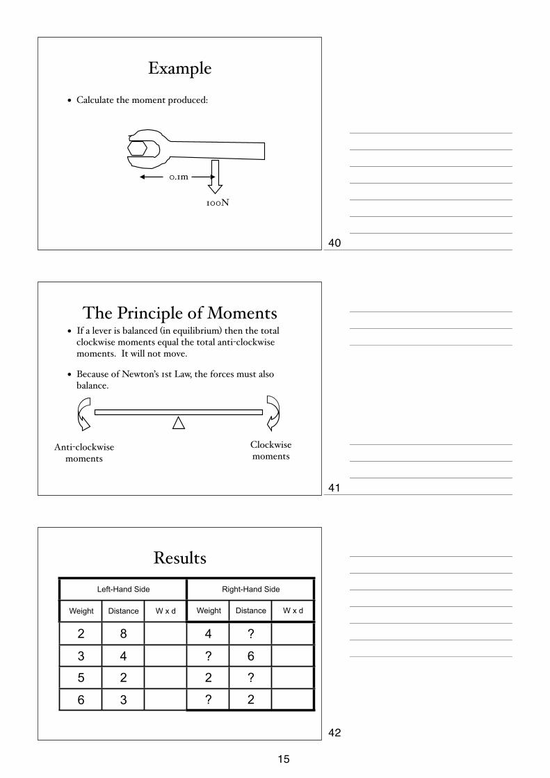
Example
• Calculate the moment produced:
0.1m
100N
The Principle of Moments• If a lever is balanced (in equilibrium) then the total
clockwise moments equal the total anti-clockwise moments. It will not move.
• Because of Newton’s 1st Law, the forces must also balance.
Anti-clockwise moments
Clockwise moments
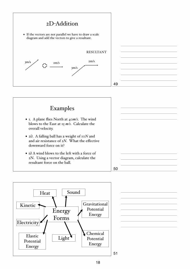
ResultsLeft-Hand Side Right-Hand Side
Weight Distance W x d Weight Distance W x d
2 8 4 ?
3 4 ? 6
5 2 2 ?
6 3 ? 2
40
41
42
15

Moments Questions
• 1. Explain why a mechanic would choose a long-arm spanner to undo a tight nut.
• 2. In the following diagram, what is the weight of X ?
X 4N
20 cm 25 cm
Uses of Levers
• Spanner
• Nutcracker
• Scissors
Centre of Mass
• Centre of mass is the point on an object that is the ‘average’ position of the mass of the object.
• The centre of gravity is a point on all objects through which forces appear to act.
• The two points are the same.
• The centres of mass of regular objects are obvious. They always lie on a line of symmetry.
• They are the point under which we place a pivot to balance the object.
43
44
45
16

Regular Objects
Stability
• Stability tells us how secure something is on the ground.
• If something is stable, then it will not topple easily.
• There are two factors to consider when changing the stability of an object:
• The area of the object’s base.
• The position of the centre of mass of the object.
• A stable object will have a BIG base, and a LOW centre of gravity.
Simple Addition
• If two vectors are parallel, then they can be simply added or subtracted to give a resultant.
3N 5N
2N
RESULTANT
46
47
48
17
2D-Addition
• If the vectors are not parallel we have to draw a scale diagram and add the vectors to give a resultant.
3m/s 2m/s
RESULTANT
3m/s
2m/s
Examples
• 1. A plane flies North at 40m/s. The wind blows to the East at 15 m/s. Calculate the overall velocity.
• 2i). A falling ball has a weight of 10N and and air resistance of 2N. What the effective downward force on it?
• ii) A wind blows to the left with a force of 2N. Using a vector diagram, calculate the resultant force on the ball.
Energy Forms
Elastic Potential Energy
Heat
Kinetic
Electricity
Sound
Gravitational Potential Energy
Chemical Potential Energy
Light
49
50
51
18
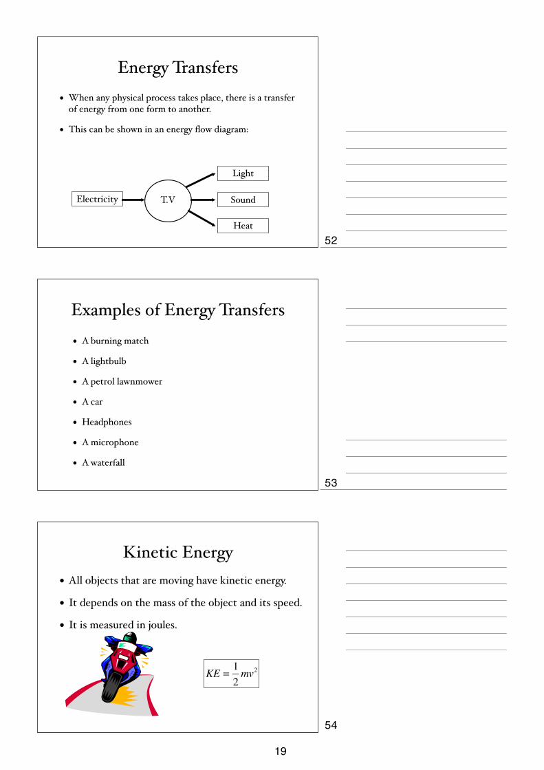
Energy Transfers• When any physical process takes place, there is a transfer
of energy from one form to another.
• This can be shown in an energy flow diagram:
T.VElectricity
Light
Sound
Heat
Examples of Energy Transfers
• A burning match
• A lightbulb
• A petrol lawnmower
• A car
• Headphones
• A microphone
• A waterfall
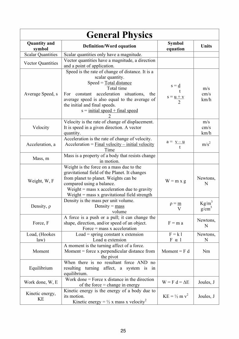
Kinetic Energy• All objects that are moving have kinetic energy.
• It depends on the mass of the object and its speed.
• It is measured in joules.
KE =12mv2
52
53
54
19

Gravitational Energy• Gravitational energy is stored in objects that
are at a height.
• It depends upon the mass of the object, and how high the object is.
• It measured in joules.
GPE = mgh
The Principle of the Conservation of Energy
• Energy cannot be created or destroyed, it simply moves from one form to another.
• When energy moves from one form to another, the total AMOUNT of energy remains the same.
• A certain amount of heat energy is always lost to the surroundings in any process.
Efficiency• Efficiency tells us how effective a process or energy transfer is.
• The more useful energy that is produced, for the least input energy, the more efficient the process is.
• Efficiency has no unit, and can be expressed as a decimal or percentage.
• It can be the ratio of power output to input, or energy output to input for a process
Efficiency =outputinput
(×100)
55
56
57
20

Work Done• Work is a type of energy change and is measured
in Joules.
• For work to be done, a force must be acting upon an object as it moves through a distance.
• The Work Done is given by:
Work Done (J )=Force(N ) × Distance(m)
Power• Power is the rate at which energy is transferred.
• It is also the rate at which Work is done.
• The unit for Power is Watts (W).
• Power is calculated from either:
or
Power(W )= Energy Change(J )Time Taken(s)
Power(W )= Work Done(J )Time Taken(s)
Calculating Personal Power
• Measure your weight in newtons.
• Measure the height of the steps in metres.
• Measure the time taken to climb the steps in seconds.
• Calculate the Work Done in joules.
• Calculate the Power of your legs in Watts.
heighttime
weight
58
59
60
21
Pressure• Pressure tells us how concentrated a force is.
• It is calculated from:
or
Stick to one set of units
Pressure(N m2 )= Force(N )Area(m2 )
Pressure(N cm2 )= Force(N )Area(cm2 )
Examples
1. Calculate the Volume of the block.
2. Calculate the block’s density.
3. Calculate the block’s weight.
4. Calculate the area in contact with the ground.
1cm
1cm
2cm
20g
Examples
• Why do camels have large flat feet?
• Why is it easier to walk in snow shoes in the snow?
61
62
63
22

Pressure in LiquidsPressure in a liquid is due to
the weight of the liquid above a point.
Pressure increases with depth.
Pressure will also increase with density of liquid (more weight).
We can calculate pressure from:
P = ρgd
Direction
• The pressure in a liquid acts in ALL directions equally at a point.
• This is why bubbles are spherical.
Questions• 1a). Draw a diagram of the cross section of a dam.
• b) Explain why it has this shape.
• 2. Calculate the pressure on a scuba diver at a depth of 20m. (The density of water is 1000kg/m3)
• 3. Describe a demonstration to show that Pressure increases with depth in a liquid.
64
65
66
23

Non-Renewable Energy Resources
• Non-Renewable resources are resources that are used up and cannot be easily replaced. Examples are fossil fuels and Nuclear fuels.
Renewable Energy Resources
• Renewable Energy Resources are energy resources that keep running and do not run-out easily.
The Energy Crisis
• Transport
• Electricity
• Fossil Fuels
• Pollution
• Depletion
Energy usage
• Energy Density
• Pollution
• Safety
Nuclear Fission
Renewable Alternatives
• Advantages
• Unreliable
• Not Controllable
• Energy Density
Nuclear Fusion
• Safety
• Pollution
• Problems
67
68
69
24
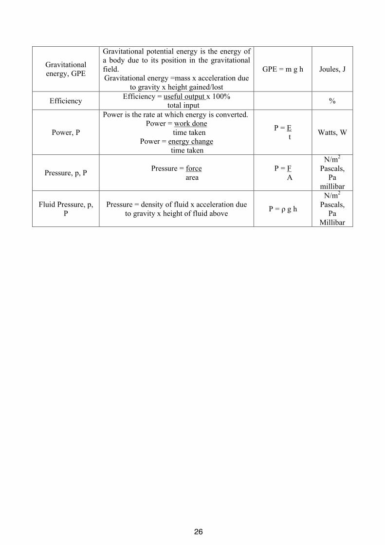
General Physics Quantity and
symbol Definition/Word equation Symbol equation Units
Scalar Quantities Scalar quantities only have a magnitude.
Vector Quantities Vector quantities have a magnitude, a direction and a point of application.
Average Speed, s
Speed is the rate of change of distance. It is a scalar quantity.
Speed = Total distance Total time
For constant acceleration situations, the average speed is also equal to the average of the initial and final speeds.
s = initial speed + final speed 2
s = d t
s = u + v 2
m/s cm/s km/h
Velocity Velocity is the rate of change of displacement. It is speed in a given direction. A vector quantity.
m/s cm/s km/h
Acceleration, a Acceleration is the rate of change of velocity. Acceleration = Final velocity – initial velocity
Time
a = v – u t m/s2
Mass, m Mass is a property of a body that resists change in motion.
Weight, W, F
Weight is the force on a mass due to the gravitational field of the Planet. It changes from planet to planet. Weights can be compared using a balance.
Weight = mass x acceleration due to gravity Weight = mass x gravitational field strength
W = m x g Newtons, N
Density, ρ Density is the mass per unit volume.
Density = mass volume
ρ = m V
Kg/m3
g/cm3
Force, F A force is a push or a pull; it can change the shape, direction, and/or speed of an object.
Force = mass x acceleration F = m a Newtons,
N
Load, (Hookes law)
Load = spring constant x extension Load α extension
F = k l F α l
Newtons, N
Moment A moment is the turning affect of a force. Moment = force x perpendicular distance from
the pivot Moment = F d Nm
Equilibrium When there is no resultant force AND no resulting turning affect, a system is in equilibrium.
Work done, W, E Work done = Force x distance in the direction of the force = change in energy W = F d = ΔE Joules, J
Kinetic energy, KE
Kinetic energy is the energy of a body due to its motion.
Kinetic energy = ½ x mass x velocity2 KE = ½ m v2 Joules, J
25
Gravitational energy, GPE
Gravitational potential energy is the energy of a body due to its position in the gravitational field. Gravitational energy =mass x acceleration due
to gravity x height gained/lost
GPE = m g h Joules, J
Efficiency Efficiency = useful output x 100% total input %
Power, P
Power is the rate at which energy is converted. Power = work done time taken
Power = energy change time taken
P = E t Watts, W
Pressure, p, P Pressure = force area
P = F A
N/m2 Pascals,
Pa millibar
Fluid Pressure, p, P
Pressure = density of fluid x acceleration due to gravity x height of fluid above P = ρ g h
N/m2 Pascals,
Pa Millibar
26

iGCSE PhysicsPast Paper QuestionsPaper 1 Compilation
General Physics
27

2
0625/1/M/J/02
1 The diagram shows the level of liquid in a measuring cylinder.
What is the volume of the liquid?
A 24 cm3 B 28 cm3 C 29 cm3 D 32 cm3
2 A cylindrical can is rolled along the ruler shown in the diagram.
The can rolls over twice.
What is the circumference (distance all round) of the can?
A 13 cm B 14 cm C 26 cm D 28 cm
0 cm 5 10 15 20 25 30 cm
mark oncan
can rolled
starting position final position
30
20
cm3
liquid
1.
2.
28

3
0625/1/M/J/02 [Turn over
3 The graph shows how the speed of a car changes with time.
Which of the following gives the distance travelled in time interval OR?
A the area OPQR
B the length PQ
C the length (QR – PO)
D the ratio QR/PO
4 A snail crosses a garden path 30 cm wide at a speed of 0.2 cm/s.
How long does the snail take?
A 0.0067 s B 6.0 s C 15 s D 150 s
5 What are correct units used for mass and for weight?
30 cmmovementof snail
snail
speed
P
Q
RO time
mass weight
A kg kg
B kg N
C N kg
D N N
3.
4.
5.
29

4
0625/1/M/J/02
6 Two objects X and Y are placed on a beam as shown. The beam balances on a pivot at itscentre.
What does this show about X and Y?
A They have the same mass and the same density.
B They have the same mass and the same weight.
C They have the same volume and the same density.
D They have the same volume and the same weight.
7 A shop-keeper places two identical blocks of cheese on a set of scales and notices that theircombined mass is 240 g. Each block measures 2.0 cm x 5.0 cm x 10.0 cm.
What is the density of the cheese?
A 0.42 g / cm3 B 0.83 g / cm3 C 1.2 g / cm3 D 2.4 g / cm3
8 The table shows the length of a wire as the load on it is increased.
Which subtraction should be made to find the extension caused by the 20 N load?
A 54.1 cm – 0 cm
B 54.1 cm – 50.0 cm
C 54.1 cm – 52.1 cm
D 56.3 cm – 54.1 cm
g
X
Y
pivot
load / N 0 10 20 30
length / cm 50.0 52.1 54.1 56.3
6.
7.
8.
30
5
0625/1/M/J/02 [Turn over
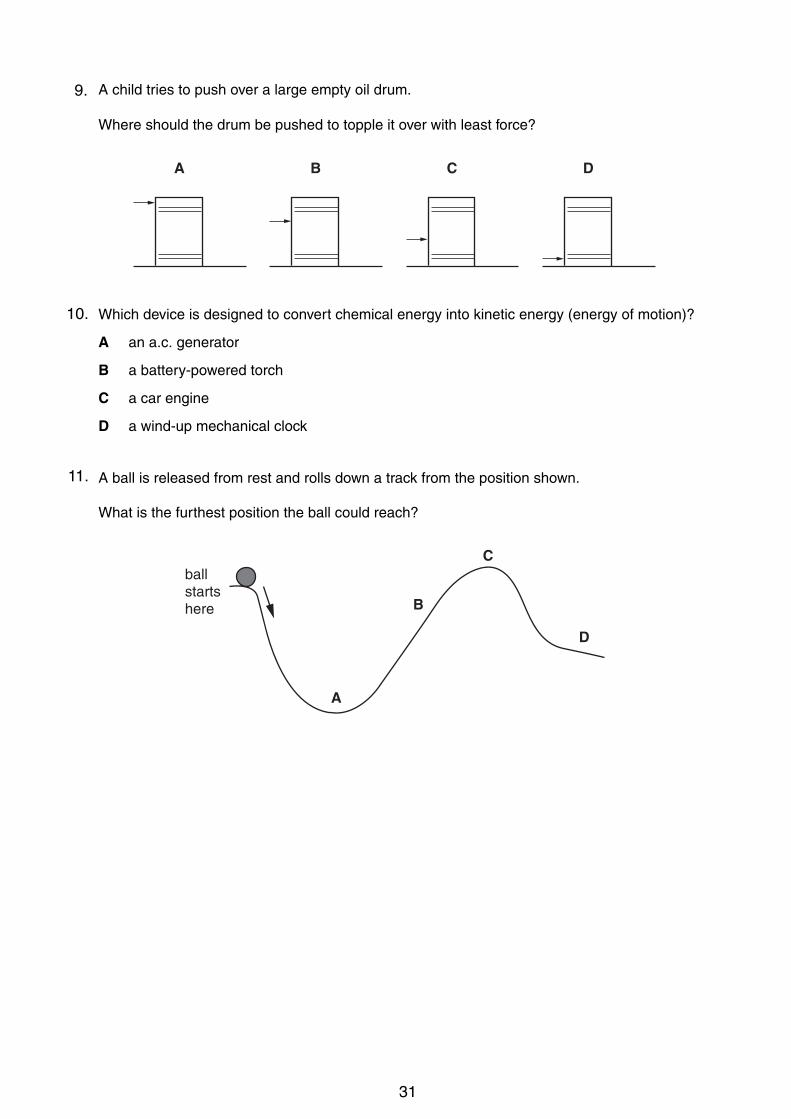
9 A child tries to push over a large empty oil drum.
Where should the drum be pushed to topple it over with least force?
10 Which device is designed to convert chemical energy into kinetic energy (energy of motion)?
A an a.c. generator
B a battery-powered torch
C a car engine
D a wind-up mechanical clock
11 A ball is released from rest and rolls down a track from the position shown.
What is the furthest position the ball could reach?
ballstartshere
A
B
C
D
A B C D
9.
10.
11.
31

6
0625/1/M/J/02
12 Two sharp nails and two blunt nails are held on a piece of wood. Each nail is hit with the samehammer with the same amount of force.
When it is hit, which nail causes the greatest pressure on the wood?
13 The diagram shows a manometer connected to a container of carbon dioxide.
Which statement correctly describes the pressure exerted by the carbon dioxide?
A It is equal to the atmospheric pressure.
B It is equal to 5 cm of mercury.
C It is equal to 5 cm of mercury above atmospheric pressure.
D It is equal to 5 cm of mercury below atmospheric pressure.
carbon dioxide
container
mercurymanometer
5 cm
A Bhammer
sharp nails
C Dhammer
blunt nails
12.
13.
32

2
0625/01/M/J/03
1 A glass tank contains some water.
The length QR and the width RS of the tank are known.
What other distance needs to be measured in order to be able to calculate the volume of thewater?
A ST B SV C TU D TV
2 A stopwatch is used to time a race. The diagrams show the watch at the start and at the end of therace.
How long did the race take?
A 45.7 s B 46.0 s C 46.5 s D 47.0 s
45
30
15
seconds
start
50
5560 5
10
20
2535
40
45
30
15
seconds
end
50
5560 5
10
20
2535
40
water
Q
R
S
T
V
U
14.
15.
33
3
0625/01/M/J/03 [Turn over
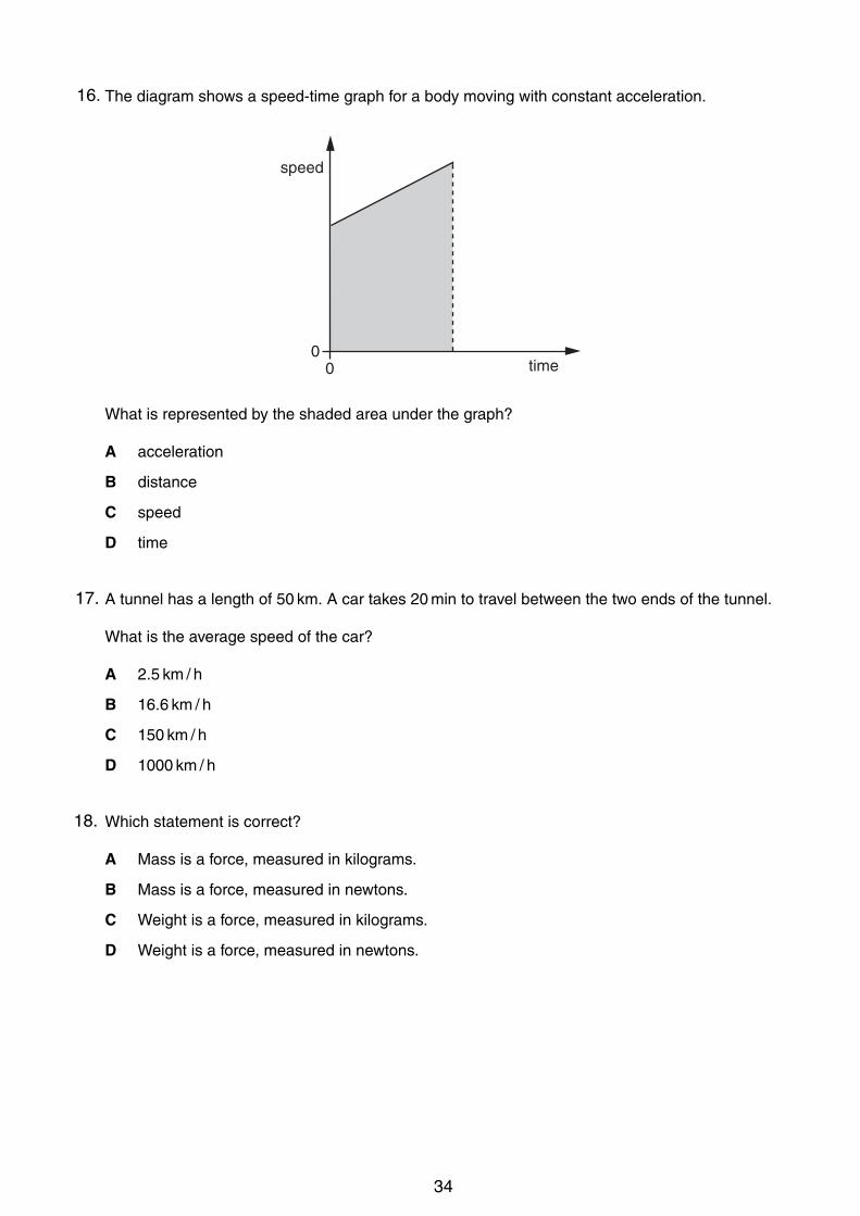
3 The diagram shows a speed-time graph for a body moving with constant acceleration.
What is represented by the shaded area under the graph?
A acceleration
B distance
C speed
D time
4 A tunnel has a length of 50 km. A car takes 20 min to travel between the two ends of the tunnel.
What is the average speed of the car?
A 2.5 km / h
B 16.6 km / h
C 150 km / h
D 1000 km / h
5 Which statement is correct?
A Mass is a force, measured in kilograms.
B Mass is a force, measured in newtons.
C Weight is a force, measured in kilograms.
D Weight is a force, measured in newtons.
speed
time0
0
16.
17.
18.
34

4
0625/01/M/J/03
6 Three children, X, Y and Z, are using a see-saw to compare their weights.
Which line in the table shows the correct order of the children’s weights?
7 What apparatus is needed to determine the density of a regularly-shaped block?
A a balance and a ruler
B a balance and a forcemeter (spring balance)
C a measuring cylinder and a ruler
D a measuring cylinder and a beaker
8 A spring is suspended from a stand. Loads are added and the extensions are measured.
Which graph shows the result of plotting extension against load?
00
exte
nsio
n
load
A
00
exte
nsio
n
load
B
00
exte
nsio
n
load
C
00
exte
nsio
n
load
D
spring
stand
loads rule
X Y Y Z X Z
heaviest !"# lightest
A X Y Z
B X Z Y
C Y X Z
D Y Z X
19.
20.
21.
35

5
0625/01/M/J/03 [Turn over
9 A student uses a stand and clamp to hold a flask of liquid.
Which diagram shows the most stable arrangement?
10 What is the source of the energy converted by a hydro-electric power station?
A hot rocks
B falling water
C oil
D waves
11 A labourer on a building site lifts heavy concrete blocks onto a lorry. Lighter blocks are now liftedthe same distance in the same time.
What happens to the work done in lifting each block and the power exerted by the labourer?
A B C D
work done in power exerted bylifting each block labourer
A decreases decreases
B decreases remains the same
C increases increases
D remains the same increases
22.
23.
24.
36
6
0625/01/M/J/03
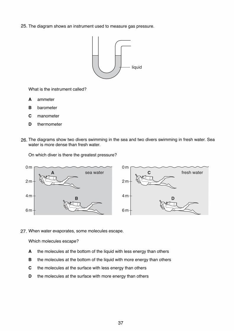
12 The diagram shows an instrument used to measure gas pressure.
What is the instrument called?
A ammeter
B barometer
C manometer
D thermometer
13 The diagrams show two divers swimming in the sea and two divers swimming in fresh water. Seawater is more dense than fresh water.
On which diver is there the greatest pressure?
14 When water evaporates, some molecules escape.
Which molecules escape?
A the molecules at the bottom of the liquid with less energy than others
B the molecules at the bottom of the liquid with more energy than others
C the molecules at the surface with less energy than others
D the molecules at the surface with more energy than others
fresh waterC
D
2 m
0 m
4 m
6 m
sea waterA
B
2 m
0 m
4 m
6 m
liquid
25.
26.
27.
37

2
U CLE S 2004 0625/01/M/J/04
1 The diagram shows a measuring cylinder.
102030405060708090100
Which unit would be most suitable for its sca le?
A mm2 B mm3 C cm2 D cm3
2 A piece of cotton is measured be tween two points on a ruler.
1cm 2 3 4 5 6 7 8 9 10 11 12 13 14 15 16
cotton
When the length of cotton is wound close ly around a pen, it goes round six times.
pen six turns of cotton
Wha t is the distance once round the pen?
A 2.2 cm B 2.6 cm C 13.2 cm D 15.6 cm
28.
29.
38

3
! UCLES 2004 0625/01/M/J/04 [Turn over
3 The diagram shows the speed-time graph for an object moving at constant speed.
2
00 3 4
time / s
speed
m/s
1
1 2
What is the distance travelled by the object in the first 3s?
A 1.5m B 2.0m C 3.0m D 6.0m
4 A small steel ball is dropped from a low balcony.
Ignoring air resistance, which statement describes its motion?
A It falls with constant acceleration.
B It falls with constant speed.
C It falls with decreasing acceleration.
D It falls with decreasing speed.
5 Which statement about the mass of a falling object is correct?
A It decreases as the object falls.
B It is equal to the weight of the object.
C It is measured in newtons.
D It stays the same as the object falls.
30.
31.
32.
39
4
! UCLES 2004 0625/01/M/J/04
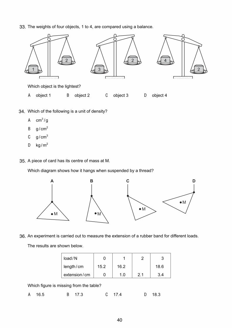
6 The weights of four objects, 1 to 4, are compared using a balance.
1
2
3
2 4
2
Which object is the lightest?
A object 1 B object 2 C object 3 D object 4
7 Which of the following is a unit of density?
A cm3
/ g
B g / cm2
C g / cm3
D kg /m2
8 A piece of card has its centre of mass at M.
Which diagram shows how it hangs when suspended by a thread?
A B C D
M MM
M
9 An experiment is carried out to measure the extension of a rubber band for different loads.
The results are shown below.
load /N 0 1 2 3
length / cm 15.2 16.2 18.6
extension / cm 0 1.0 2.1 3.4
Which figure is missing from the table?
A 16.5 B 17.3 C 17.4 D 18.3
33.
34.
35.
36.
40
5
! UCLES 2004 0625/01/M/J/04 [Turn over
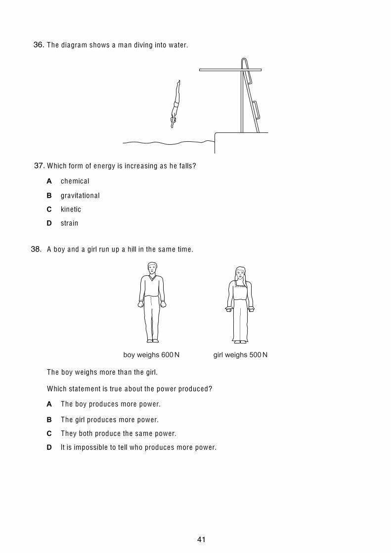
10 The diagram shows a man diving into wa ter.
Which form of energy is increasing as he fa lls?
A chemica l
B gravita tiona l
C kine tic
D stra in
11 A boy and a girl run up a hill in the same time .
boy weighs 600 N girl weighs 500 N
The boy we ighs more than the girl.
Which sta tement is true about the power produced?
A The boy produces more power.
B The girl produces more power.
C They both produce the same power.
D It is impossible to te ll who produces more power.
36.
37.
38.
41

6
U CLE S 2004 0625/01/M/J/04
12 The diagram shows a simple mercury barome ter. The barome ter reading is h cm of mercury.
mercury
S
h
Wha t is the pressure a t S?
A approxima te ly zero
B a tmospheric pressure
C a tmospheric pressure + h cm of mercury
D h cm of mercury
13 Two boys X and Y each have the same tota l we ight and are standing on soft ground.
X Y
Which boy is more like ly to sink into the soft ground and why?
boy morelike ly to sink
pressure on soft ground
A X larger than Y
B X sma ller than Y
C Y larger than X
D Y sma ller than X
39.
40.
41.
42

2
© UCLES 2005 0625/01/M/J/05
1 A decorator wishes to calculate the area of a bathroom tile so that he can estimate the amount of
adhesive that he needs to buy.
What must he use?
A a measuring cylinder only
B a ruler only
C a measuring cylinder and a clock only
D a measuring cylinder and a ruler only
2 The three balls shown are dropped from a bench.
aluminium lead wood
Which balls have the same acceleration?
A aluminium and lead only
B aluminium and wood only
C lead and wood only
D aluminium, lead and wood
3 A car accelerates from traffic lights. The graph shows how the car’s speed changes with time.
time / s
20
100
0
speed
m / s
How far does the car travel before it reaches a steady speed?
A 10 m B 20 m C 100 m D 200 m
42.
43.
44.
43

3
© UCLES 2005 0625/01/M/J/05 [Turn over
4 Which statement is correct?
A The mass of a bottle of water at the North Pole is different from its mass at the Equator.
B The mass of a bottle of water is measured in newtons.
C The weight of a bottle of water and its mass are the same thing.
D The weight of a bottle of water is one of the forces acting on it.
5 Two blocks X and Y are placed on a beam as shown. The beam balances on a pivot at its centre.
XY
pivot
What does this show about X and Y?
A They have the same mass and the same density.
B They have the same mass and the same weight.
C They have the same volume and the same density.
D They have the same volume and the same weight.
6 The masses of a measuring cylinder before and after pouring some liquid into it are shown in the
diagram.
200
100
cm3
mass = 80 g
200
100
cm3
mass = 180 g
liquid
What is the density of the liquid?
A
120
100g / cm
3
B
140
100g / cm
3
C
120
180g / cm
3
D
140
180g / cm
3
45.
46.
47.
44

4
© UCLES 2005 0625/01/M/J/05
7 A girl and a boy are pulling in opposite directions on a rope. The forces acting on the rope are
shown in the diagram.
200 N
rope
150 N
girl boy
Which single force has the same effect as the two forces shown?
A 50 N acting towards the girl
B 350 N acting towards the girl
C 50 N acting towards the boy
D 350 N acting towards the boy
8 Objects with different masses are hung on a 10 cm spring. The diagram shows how much the
spring stretches.
100 g
M
10 cm
20 cm
30 cm
The extension of the spring is directly proportional to the mass hung on it.
What is the mass of object M?
A 110 g B 150 g C 200 g D 300 g
48.
49.
50.
45

5
© UCLES 2005 0625/01/M/J/05 [Turn over
9 What is designed to change electrical energy into kinetic energy?
A capacitor
B generator
C motor
D transformer
10 A power station uses nuclear fission to obtain energy.
In this process, nuclear energy is first changed into
A chemical energy.
B electrical energy.
C gravitational energy.
D internal energy.
11 A ball is released from rest and rolls down a track from the position shown.
What is the furthest position the ball could reach?
A
B
C
D
ballstartshere
51.
52.
53.
46

6
© U CLE S 2005 0625/01/M/J/05
12 A water manometer is used to measure the pressure of a gas supply to a house. It gives a
reading of h cm of water.
gassupply
h cm
Why is it better to use water rather than mercury in this manometer?
A h would be too large if mercury were used.
B h would be too small if mercury were used.
C The tube would need to be narrower if mercury were used.
D The tube would need to be wider if mercury were used.
13 A farmer has two carts. The carts have the same weight, but one has four narrow wheels and the
other has four wide wheels.
narrow wheel wide wheel
In rainy weather, which cart sinks less into soft ground, and why?
cart wheels why
A narrow greater pressure on the ground
B narrow less pressure on the ground
C wide greater pressure on the ground
D wide less pressure on the ground
54.
55.
56.
47

2
© UCLES 2006 0625/01/M/J/06
1 A measuring cylinder contains some water. When a stone is put in the water, the level rises.
150
100
50
cm3
150
100
50
cm3
200 200
stone
What is the volume of the stone?
A 50 cm3 B 70 cm
3 C 75 cm
3 D 125 cm
3
2 The graph represents the movement of a body accelerating from rest.
1 2 3 4 5
10
8
6
4
2
0
time / s
speedm / s
After 5 seconds how far has the body moved?
A 2 m B 10 m C 25 m D 50 m
3 A child is standing on the platform of a station, watching the trains.
A train travelling at 30 m / s takes 3 s to pass the child.
What is the length of the train?
A 10 m B 30 m C 90 m D 135 m
57.
58.
59.
48
3
© UCLES 2006 0625/01/M/J/06 [Turn over
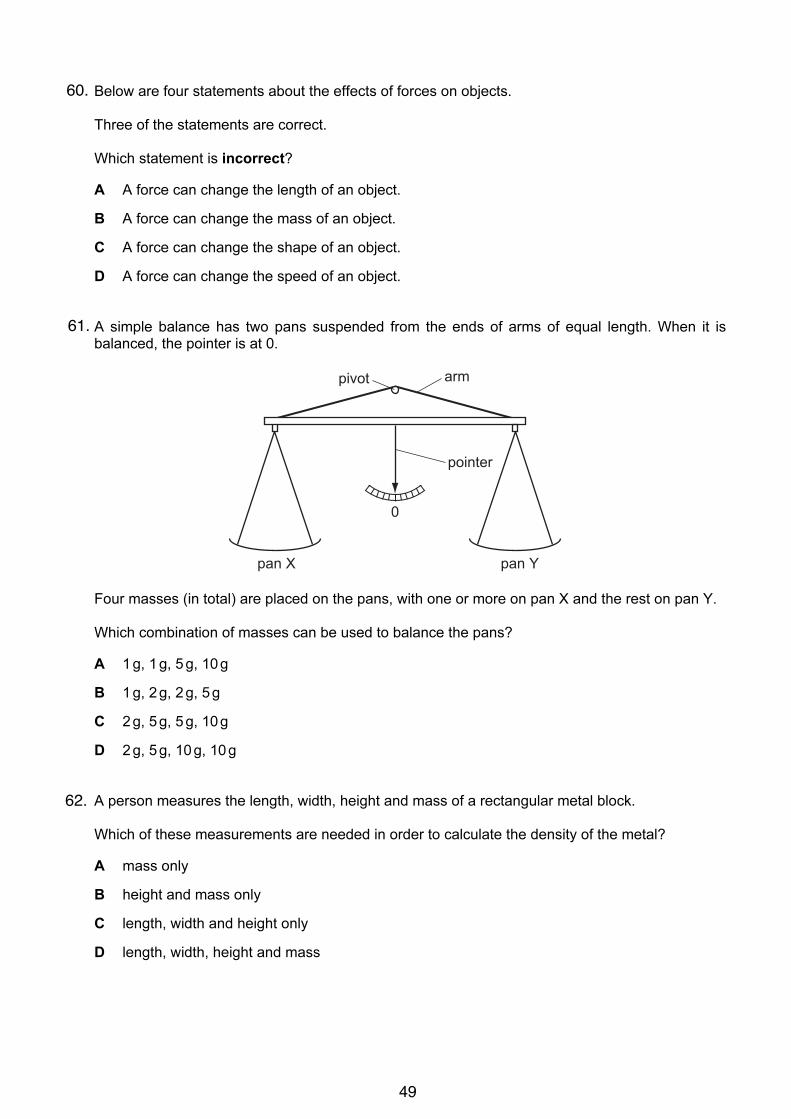
4 Below are four statements about the effects of forces on objects.
Three of the statements are correct.
Which statement is incorrect?
A A force can change the length of an object.
B A force can change the mass of an object.
C A force can change the shape of an object.
D A force can change the speed of an object.
5 A simple balance has two pans suspended from the ends of arms of equal length. When it is
balanced, the pointer is at 0.
0
pointer
pan X pan Y
armpivot
Four masses (in total) are placed on the pans, with one or more on pan X and the rest on pan Y.
Which combination of masses can be used to balance the pans?
A 1 g, 1 g, 5 g, 10 g
B 1 g, 2 g, 2 g, 5 g
C 2 g, 5 g, 5 g, 10 g
D 2 g, 5 g, 10 g, 10 g
6 A person measures the length, width, height and mass of a rectangular metal block.
Which of these measurements are needed in order to calculate the density of the metal?
A mass only
B height and mass only
C length, width and height only
D length, width, height and mass
60.
61.
62.
49

4
© UCLES 2006 0625/01/M/J/06
7 Two forces act on an object.
In which situation is it impossible for the object to be in equilibrium?
A The two forces act in the same direction.
B The two forces act through the same point.
C The two forces are of the same type.
D The two forces are the same size.
8 The diagram shows four models of buses placed on different ramps.
centreof mass
centreof mass
centreof mass
centreof mass
How many of these models will fall over?
A 1 B 2 C 3 D 4
9 Which form of energy do we receive directly from the Sun?
A chemical
B light
C nuclear
D sound
10 A labourer on a building site lifts a heavy concrete block onto a lorry. He then lifts a light block the
same distance in the same time.
Which of the following is true?
work done in lifting the
blocks power exerted by labourer
A less for the light block less for the light block
B less for the light block the same for both blocks
C more for the light block more for the light block
D the same for both blocks more for the light block
63.
64.
65.
66.
50
5
© U CLE S 2006 0625/01/M/J/06 [Turn over
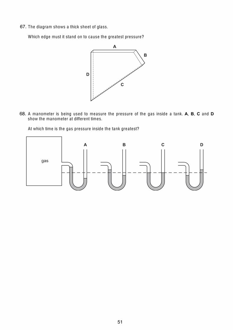
11 The diagram shows a thick shee t of glass.
Which edge must it stand on to cause the grea test pressure?
A
D
C
B
12 A manome ter is be ing used to measure the pressure of the gas inside a tank. A, B, C and D
show the manome ter a t different times.
A t which time is the gas pressure inside the tank grea test?
gas
A B C D
13 Brownian motion is seen by looking a t smoke particles through a microscope .
How do the smoke particles move in Brownian motion?
A a ll in the same direction
B a t random
C in circles
D vibra ting about fixed points
67.
68.
51

iGCSE PhysicsPast Paper QuestionsPaper 3 Compilation
General Physics
52

2
0625/3/M/J/02
1 A group of students attempts to find out how much power each student can generate. Thestudents work in pairs in order to find the time taken for each student to run up a flight ofstairs. The stairs used are shown in Fig. 1.1.
Fig. 1.1
(a) Make a list of all the readings that would be needed. Where possible, indicate how theaccuracy of the readings could be improved.
..........................................................................................................................................
..........................................................................................................................................
..........................................................................................................................................
..........................................................................................................................................
..........................................................................................................................................
..................................................................................................................................... [4]
(b) Using words, not symbols, write down all equations that would be needed to work outthe power of a student.
..........................................................................................................................................
..........................................................................................................................................
..................................................................................................................................... [2]
(c) (i) When the student has reached the finishing point and is standing at the top of thestairs, what form of energy has increased to its maximum?
...................................................................................................................................
(ii) Suggest why the total power of the student is greater than the power calculated bythis method.
...................................................................................................................................
...................................................................................................................................[3]
starting point
finishing point
ForExaminer’s
Use1.
53
3
0625/3/M/J/02 [Turn over
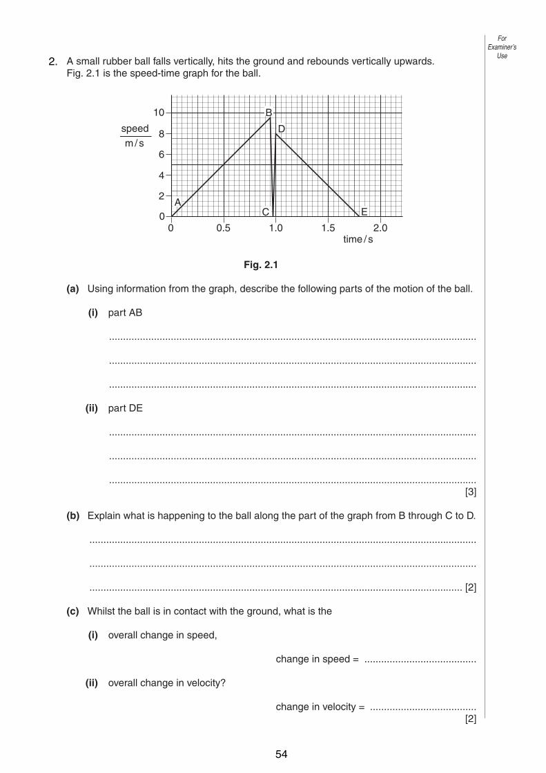
2 A small rubber ball falls vertically, hits the ground and rebounds vertically upwards.Fig. 2.1 is the speed-time graph for the ball.
Fig. 2.1
(a) Using information from the graph, describe the following parts of the motion of the ball.
(i) part AB
...................................................................................................................................
...................................................................................................................................
...................................................................................................................................
(ii) part DE
...................................................................................................................................
...................................................................................................................................
...................................................................................................................................[3]
(b) Explain what is happening to the ball along the part of the graph from B through C to D.
..........................................................................................................................................
..........................................................................................................................................
..................................................................................................................................... [2]
(c) Whilst the ball is in contact with the ground, what is the
(i) overall change in speed,
change in speed = ........................................
(ii) overall change in velocity?
change in velocity = ......................................[2]
10
8
6
4
2
00
0.5 1.0 1.5 2.0time / s
speedm/s
B
D
C EA
ForExaminer’s
Use2.
54

4
0625/3/M/J/02
(d) Use your answer to (c) to explain the difference between speed and velocity.
..........................................................................................................................................
..........................................................................................................................................
..................................................................................................................................... [2]
(e) Use the graph to calculate the distance travelled by the ball between D and E.
distance travelled = ..................................[2]
(f) Use the graph to calculate the deceleration of the ball between D and E.
deceleration = ..................................[2]
ForExaminer’s
Use
55
2
0625/3/M/J/03
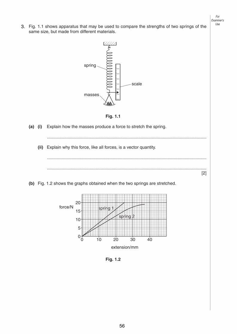
1 Fig. 1.1 shows apparatus that may be used to compare the strengths of two springs of thesame size, but made from different materials.
Fig. 1.1
(a) (i) Explain how the masses produce a force to stretch the spring.
...................................................................................................................................
(ii) Explain why this force, like all forces, is a vector quantity.
...................................................................................................................................
...................................................................................................................................[2]
(b) Fig. 1.2 shows the graphs obtained when the two springs are stretched.
Fig. 1.2
00
5
10
15
20force/N
10 20 30 40
extension/mm
spring 1spring 1
spring 2spring 2
spring 1
spring 2
spring
masses
scale
ForExaminer’s
Use3.
56

3
0625/3/M/J/03 [Turn over
(i) State which spring is more difficult to extend. Quote values from the graphs tosupport your answer.
...................................................................................................................................
...................................................................................................................................
...................................................................................................................................
...................................................................................................................................
(ii) On the graph of spring 2, mark a point P at the limit of proportionality. Explain yourchoice of point P.
...................................................................................................................................
...................................................................................................................................
...................................................................................................................................
(iii) Use the graphs to find the difference in the extensions of the two springs when aforce of 15 N is applied to each one.
difference in extensions = ..................................[6]
2 The speed of a cyclist reduces uniformly from 2.5 m/s to 1.0 m/s in 12 s.
(a) Calculate the deceleration of the cyclist.
deceleration = ..................................[3]
(b) Calculate the distance travelled by the cyclist in this time.
distance = ..................................[2]
ForExaminer’s
Use
4.
57

4
0625/3/M/J/03
3 Fig. 3.1 shows the arm of a crane when it is lifting a heavy box.
Fig. 3.1
(a) By the use of a scale diagram (not calculation) of the forces acting at P, find the weightof the box. [5]
40° 30°
950N1220 N
P
box
ForExaminer’s
Use5.
58
5
0625/3/M/J/03 [Turn over
(b) Another box of weight 1500 N is raised vertically by 3.0 m.
(i) Calculate the work done on the box.
work done = ..................................
(ii) The crane takes 2.5 s to raise this box 3.0 m. Calculate the power output of thecrane.
power = ..................................[4]
4 Fig. 4.1 shows a sealed glass syringe that contains air and many very tiny suspended dustparticles.
Fig. 4.1
(a) Explain why the dust particles are suspended in the air and do not settle to the bottom.
..........................................................................................................................................
..........................................................................................................................................
..........................................................................................................................................
......................................................................................................................................[3]
(b) The air in the syringe is at a pressure of 2.0 ! 105 Pa. The piston is slowly moved into thesyringe, keeping the temperature constant, until the volume of the air is reduced from80 cm3 to 25 cm3. Calculate the final pressure of the air.
pressure = ..................................[3]
syringeseal
dust particles
piston
ForExaminer’s
Use
59

2
0625/03 M/J/04
1 Fig. 1.1 shows a cycle track.
Fig. 1.1
A cyclist starts at A and follows the path ABCDEB.
The speed-time graph is shown in Fig. 1.2.
Fig. 1.2
(a) Use information from Fig. 1.1 and Fig. 1.2 to describe the motion of the cyclist
(i) along AB,
...................................................................................................................................
(ii) along BCDEB.
...................................................................................................................................
...................................................................................................................................[4]
0
1
0
2
3
4
5
6
30 40 5010 20 60 70 80 90 100time / s
speed m / s
A
B C D E B
A B
E C
D
v = 6 m/s
ForExaminer’s
Use
© UCLES 2004
6.
60

3
0625/03 M/J/04 [Turn over
(b) The velocity v of the cyclist at C is shown in Fig. 1.1.
State one similarity and one difference between the velocity at C and the velocity at E.
similarity ...........................................................................................................................
difference ......................................................................................................................[2]
(c) Calculate
(i) the distance along the cycle track from A to B,
distance = …………………
(ii) the circumference of the circular part of the track.
circumference = …………………[4]
ForExaminer’s
Use
© UCLES 2004
61
4
0625/03 M/J/04
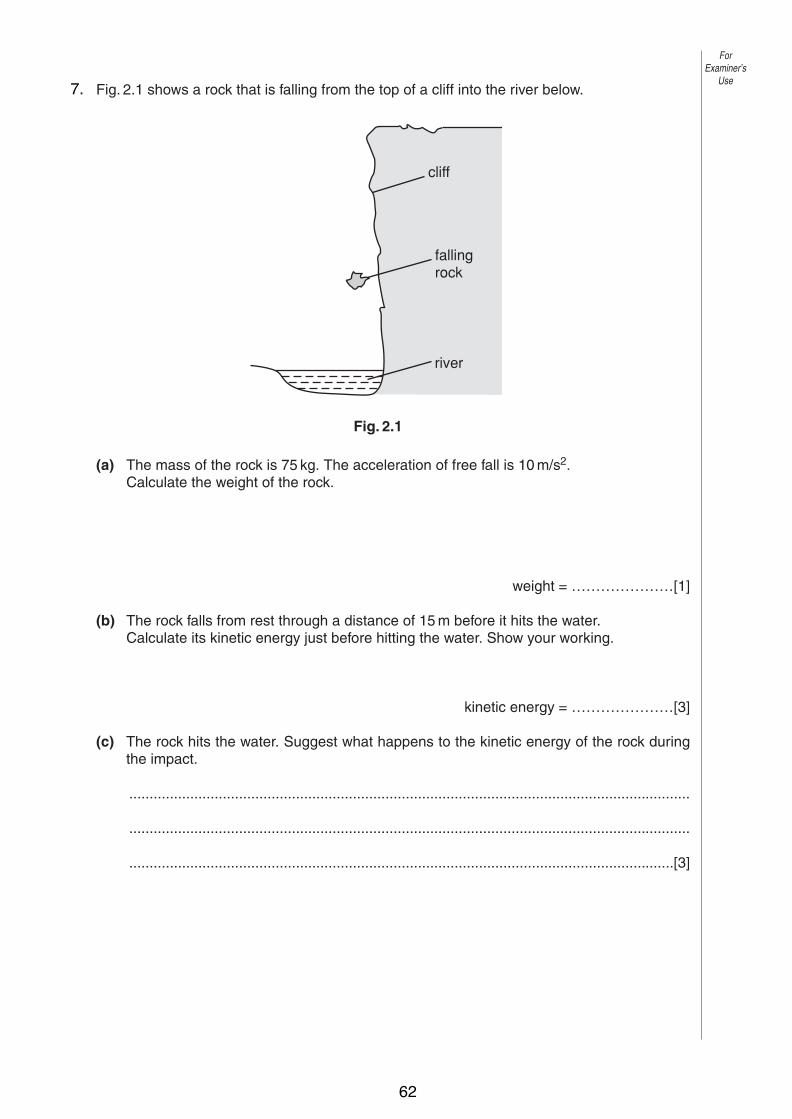
2 Fig. 2.1 shows a rock that is falling from the top of a cliff into the river below.
Fig. 2.1
(a) The mass of the rock is 75 kg. The acceleration of free fall is 10 m/s2.Calculate the weight of the rock.
weight = …………………[1]
(b) The rock falls from rest through a distance of 15 m before it hits the water.Calculate its kinetic energy just before hitting the water. Show your working.
kinetic energy = …………………[3]
(c) The rock hits the water. Suggest what happens to the kinetic energy of the rock duringthe impact.
..........................................................................................................................................
..........................................................................................................................................
......................................................................................................................................[3]
cliff
falling rock
river
ForExaminer’s
Use
© UCLES 2004
7.
62

5
0625/03 M/J/04 [Turn over
3 A large spring is repeatedly stretched by an athlete to increase the strength of his arms.Fig. 3.1 is a table showing the force required to stretch the spring.
Fig. 3.1
(a) (i) State Hooke’s law.
...................................................................................................................................
...............................................................................................................................[1]
(ii) Use the results in Fig. 3.1 to show that the spring obeys Hooke’s law.
[1]
(b) Another athlete using a different spring exerts an average force of 400 N to enable herto extend the spring by 0.210 m.
(i) Calculate the work done by this athlete in extending the spring once.
work done = …………………
(ii) She is able to extend the spring by this amount and to release it 24 times in 60 s.Calculate the power used by this athlete while doing this exercise.
power = …………………[4]
ForExaminer’s
Use
© UCLES 2004
extension of spring/m 0.096 0.192 0.288 0.384
force exerted to produce extension/N 250 500 750 1000
8.
63

2
0625/03/M/J/05
1 A solid plastic sphere falls towards the Earth.
Fig. 1.1 is the speed-time graph of the fall up to the point where the sphere hits the Earth’ssurface.
Fig. 1.1
(a) Describe in detail the motion of the sphere shown by the graph.
..........................................................................................................................................
..........................................................................................................................................
..........................................................................................................................................
..........................................................................................................................................
..................................................................................................................................... [3]
0
20
P
Q
R S T
40
60
80
100
120
140
speedm / s
100 20 30 40 50 60 70 80 90 100 110time / s
ForExaminer’s
Use
© UCLES 2005
9.
64

3
0625/03/M/J/05 [Turn over
(b) On Fig. 1.2, draw arrows to show the directions of the forces acting on the sphere whenit is at the position shown by point S on the graph. Label your arrows with the names ofthe forces. [2]
Fig. 1.2
(c) Explain why the sphere is moving with constant speed at S.
..........................................................................................................................................
..........................................................................................................................................
..................................................................................................................................... [2]
(d) Use the graph to calculate the approximate distance that the sphere falls
(i) between R and T,
distance = ………………. [2](ii) between P and Q.
distance = ………………. [2]
ForExaminer’s
Use
© UCLES 2005
65
4
0625/03/M/J/05
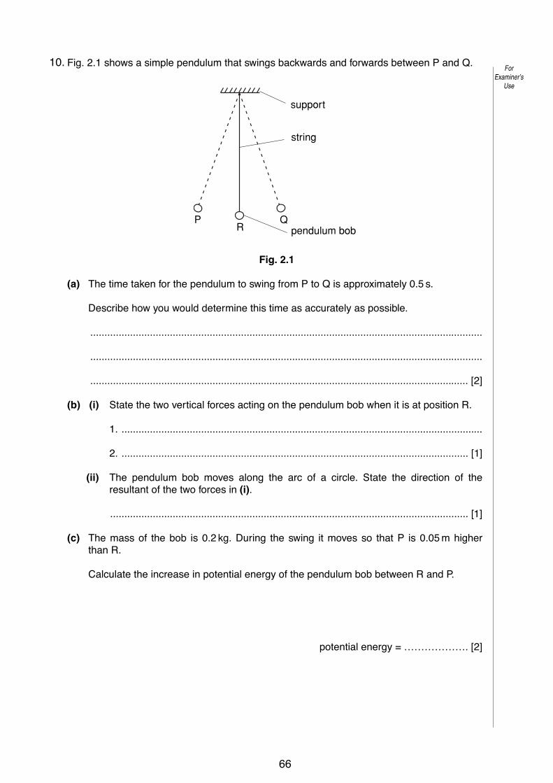
2 Fig. 2.1 shows a simple pendulum that swings backwards and forwards between P and Q.
Fig. 2.1
(a) The time taken for the pendulum to swing from P to Q is approximately 0.5 s.
Describe how you would determine this time as accurately as possible.
..........................................................................................................................................
..........................................................................................................................................
..................................................................................................................................... [2]
(b) (i) State the two vertical forces acting on the pendulum bob when it is at position R.
1. ...............................................................................................................................
2. .......................................................................................................................... [1]
(ii) The pendulum bob moves along the arc of a circle. State the direction of theresultant of the two forces in (i).
.............................................................................................................................. [1]
(c) The mass of the bob is 0.2 kg. During the swing it moves so that P is 0.05 m higher than R.
Calculate the increase in potential energy of the pendulum bob between R and P.
potential energy = ………………. [2]
support
string
pendulum bobP
RQ
ForExaminer’s
Use
© UCLES 2005
10.
66
5
0625/03/M/J/05 [Turn over
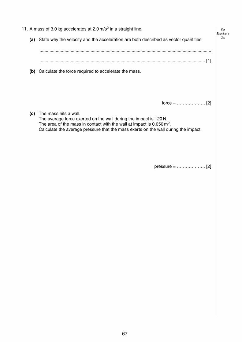
3 A mass of 3.0 kg accelerates at 2.0 m/s2 in a straight line.
(a) State why the velocity and the acceleration are both described as vector quantities.
..........................................................................................................................................
..................................................................................................................................... [1]
(b) Calculate the force required to accelerate the mass.
force = ………………. [2]
(c) The mass hits a wall.The average force exerted on the wall during the impact is 120 N.The area of the mass in contact with the wall at impact is 0.050 m2.Calculate the average pressure that the mass exerts on the wall during the impact.
pressure = ………………. [2]
ForExaminer’s
Use
© UCLES 2005
11.
67

2
0625/03/M/J/06
ForExaminer’s
Use
© UCLES 2006
1 A bus travels from one bus stop to the next. The journey has three distinct parts. Stated in order they are
uniform acceleration from rest for 8.0 s, uniform speed for 12 s, non-uniform deceleration for 5.0 s. Fig. 1.1 shows only the deceleration of the bus.
5
0
10
15
5 0 10 15 20 25
speed m/s
time/s
Fig. 1.1
(a) On Fig. 1.1, complete the graph to show the first two parts of the journey. [3]
(b) Calculate the acceleration of the bus 4.0 s after leaving the first bus stop.
acceleration = ........................[2]
(c) Use the graph to estimate the distance the bus travels between 20 s and 25 s.
estimated distance = ........................[2]
(d) On leaving the second bus stop, the uniform acceleration of the bus is 1.2 m / s2. The mass of the bus and passengers is 4000 kg.
Calculate the accelerating force that acts on the bus.
force = ........................[2]
(e) The acceleration of the bus from the second bus stop is less than that from the first bus stop.
Suggest two reasons for this.
1. ......................................................................................................................................
..........................................................................................................................................
2. ......................................................................................................................................
......................................................................................................................................[2]
12.
68

3
0625/03/M/J/06 [Turn over
ForExaminer’s
Use
© UCLES 2006
2 A student sets up the apparatus shown in Fig. 2.1 in order to find the resultant of the two tensions T1 and T2 acting at P. When the tensions T1, T2 and T3 are balanced, the angles between T1 and the vertical and T2 and the vertical are as marked on Fig. 2.1.
verticalboard
pulley
pulley
69° 44°
P
T1 = 6.0 N T2 = 8.0 N
T3
Fig. 2.1
In the space below, draw a scale diagram of the forces T1 and T2. Use the diagram to find the resultant of the two forces.
State
(a) the scale used, scale = ........................................
(b) the value of the resultant, value = ........................................
(c) the direction of the resultant. direction = ........................................ [6]
13.
69
4
0625/03/M/J/06
ForExaminer’s
Use
© UCLES 2006
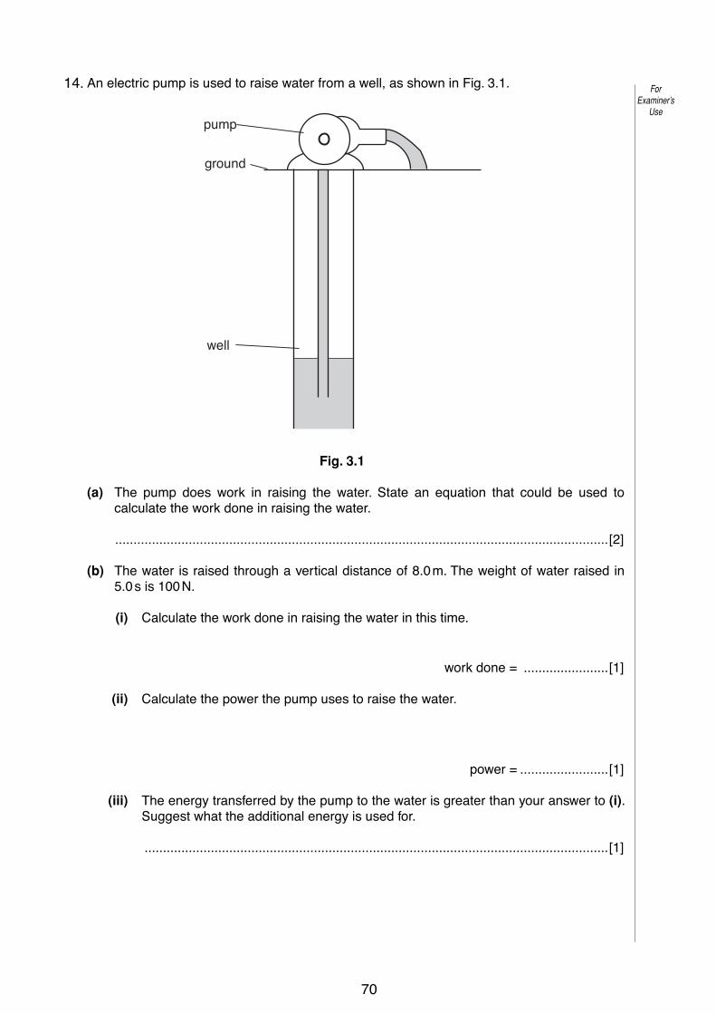
3 An electric pump is used to raise water from a well, as shown in Fig. 3.1.
pump
ground
well
Fig. 3.1
(a) The pump does work in raising the water. State an equation that could be used to calculate the work done in raising the water.
......................................................................................................................................[2]
(b) The water is raised through a vertical distance of 8.0 m. The weight of water raised in 5.0 s is 100 N.
(i) Calculate the work done in raising the water in this time.
work done = .......................[1]
(ii) Calculate the power the pump uses to raise the water.
power = ........................[1]
(iii) The energy transferred by the pump to the water is greater than your answer to (i). Suggest what the additional energy is used for.
..............................................................................................................................[1]
14.
70

Topic 2:Thermal Physics
Solids• The particles in solids are tightly held together by strong
forces.
• They vibrate around mean positions.
• The higher the temperature, the more vibrational kinetic energy the particles have.
• Solids have a rigid shape.
Liquids• In liquids the forces are strong, but the vibrating
particles are not fixed in position.
• The particles can move but they are held close to their neighbours.
• Liquids do not keep their shape.
1
2
3
71

Gases• In gases the forces are very weak and they are virtually
free to move around their container.
• The particles occasionally collide.
• Gases expand to fill their container.
• The collisions between the particles and the container walls provides pressure.
Changing State• When a material changes from one state to another,
bonds are either broken or created.
• When bonds are broken, heat must be supplied. When bonds are created, heat is released.
• When materials change state there is no change in the temperature.
Phase Changes• The phase change from solid to liquid is called ‘fusion’.
• The phase change from liquid to gas is called ‘vaporisation’.
• The energy required to effect the phase change is called the ‘Latent Heat’.
• The Latent Heat required per kg is called the ‘Specific Latent Heat’.
4
5
6
72

Phases Changes (Graphical)Temperature
Time
fusion
vaporisation
liquid water
Latent Heat Calculations
• The Specific Latent Heat of a material is given the symbol l.
• From the definition, we have the following relationship:
H - Jm - kgl - J/kg
H = ml
Heat Capacity
• Whilst a material is being heated within a certain state of matter, its temperature will rise.
• The temperature rise depends upon the mass of the material, the type of material and the amount of heat supplied.
• The property of a material that represents how much heat is needed to raise its temperature is called its ‘Specific Heat Capacity’ and is given the symbol c.
7
8
9
73
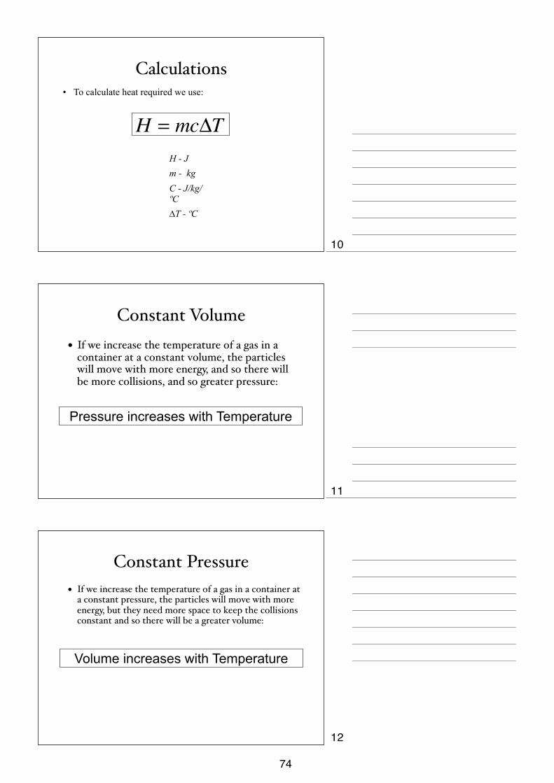
Calculations• To calculate heat required we use:
H - Jm - kgC - J/kg/ºC∆T - ºC
H = mcΔT
Constant Volume • If we increase the temperature of a gas in a
container at a constant volume, the particles will move with more energy, and so there will be more collisions, and so greater pressure:
Pressure increases with Temperature
Constant Pressure • If we increase the temperature of a gas in a container at
a constant pressure, the particles will move with more energy, but they need more space to keep the collisions constant and so there will be a greater volume:
Volume increases with Temperature
10
11
12
74

Constant Temperature• If we keep the temperature of a gas constant, we
keep the kinetic energy of the particles constant.
• Decreasing the volume of the gas’ container will increase the number of collisions of the particles with the container.
• The pressure of the gas will increase.
• Pressure and Volume changes are described by the following relationship:
P1V1 = P2V2
Brownian Motion• When pollen grains are placed on the surface of a
liquid and a strong light source is used to illuminate the pollen, the pollen is seen to move randomly.
• This movement is called ‘Brownian Motion’ and cause by the invisible water particles hitting the pollen grains.
Expansion
• When particles are heated they gain energy.
• They become more spaced-out, and the material gets bigger.
• We say that the material expands.
• Generally, objects expand as they get hotter and contract as they get cooler.
• Liquids expand more than solids on heating, and gases expand more than liquids.
• Solids expand with the greatest force. Gases expand with the least force.
13
14
15
75
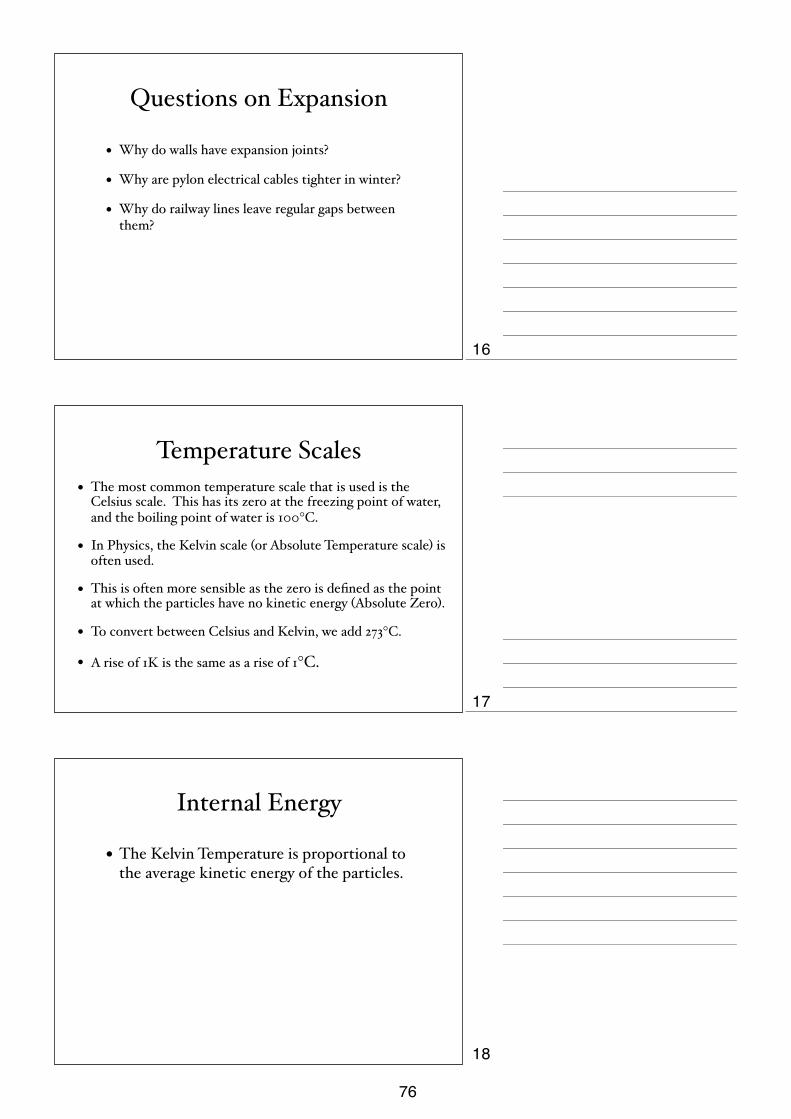
Questions on Expansion
• Why do walls have expansion joints?
• Why are pylon electrical cables tighter in winter?
• Why do railway lines leave regular gaps between them?
Temperature Scales• The most common temperature scale that is used is the
Celsius scale. This has its zero at the freezing point of water, and the boiling point of water is 100°C.
• In Physics, the Kelvin scale (or Absolute Temperature scale) is often used.
• This is often more sensible as the zero is defined as the point at which the particles have no kinetic energy (Absolute Zero).
• To convert between Celsius and Kelvin, we add 273°C.
• A rise of 1K is the same as a rise of 1°C.
Internal Energy
• The Kelvin Temperature is proportional to the average kinetic energy of the particles.
16
17
18
76
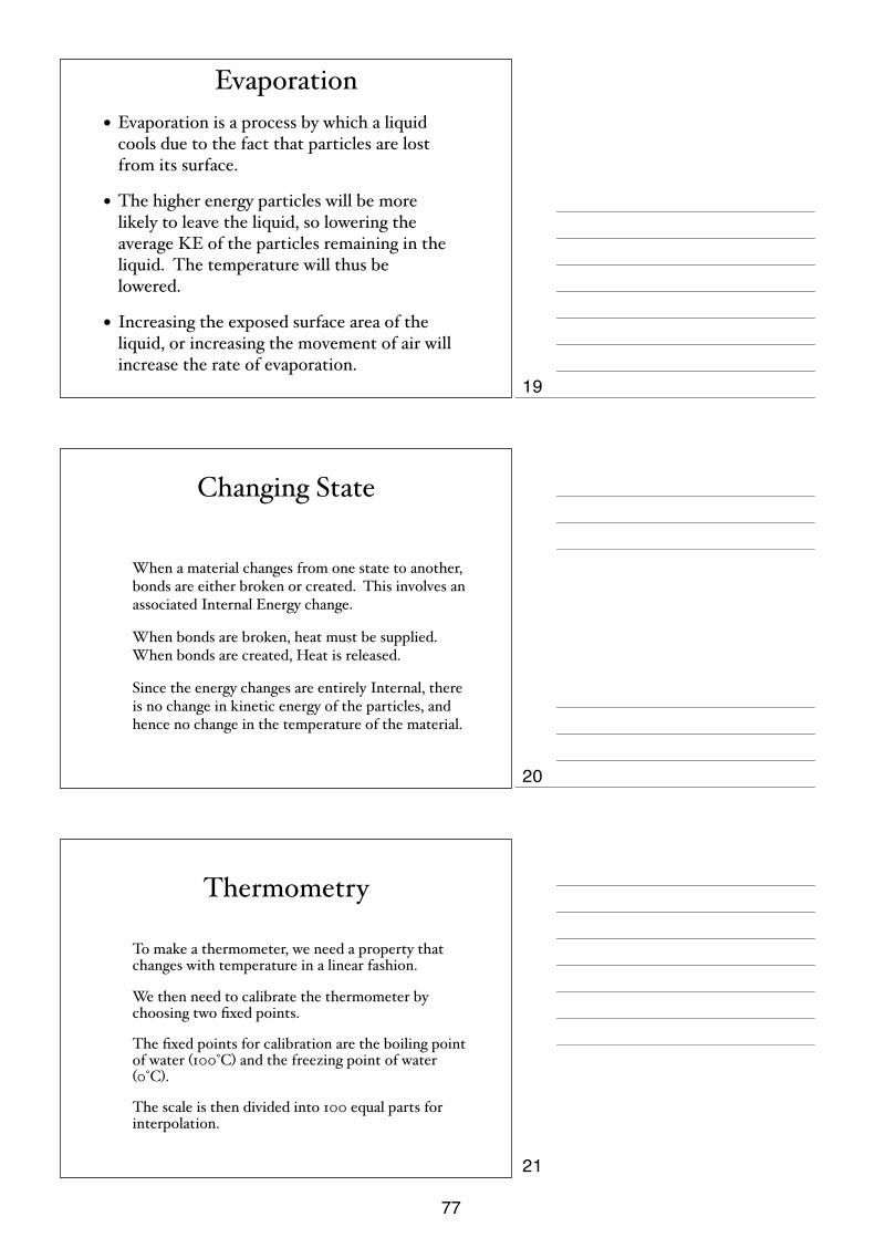
Evaporation• Evaporation is a process by which a liquid
cools due to the fact that particles are lost from its surface.
• The higher energy particles will be more likely to leave the liquid, so lowering the average KE of the particles remaining in the liquid. The temperature will thus be lowered.
• Increasing the exposed surface area of the liquid, or increasing the movement of air will increase the rate of evaporation.
Changing State
When a material changes from one state to another, bonds are either broken or created. This involves an associated Internal Energy change.
When bonds are broken, heat must be supplied. When bonds are created, Heat is released.
Since the energy changes are entirely Internal, there is no change in kinetic energy of the particles, and hence no change in the temperature of the material.
Thermometry
To make a thermometer, we need a property that changes with temperature in a linear fashion.
We then need to calibrate the thermometer by choosing two fixed points.
The fixed points for calibration are the boiling point of water (100°C) and the freezing point of water (0°C).
The scale is then divided into 100 equal parts for interpolation.
19
20
21
77

Liquid in Glass Thermometers• Liquid in glass thermometers have liquid in
a glass bulb. As the liquid is heated it expands and its level rises up the scale.
• The choice of liquid, the thinness of the bore or the size of the bulb will affect the sensitivity of the thermometer.
• The choice of liquid will affect the range of the thermometer.
Thermocouple• A thermocouple is a junction of two different metals.
• Electrons will move across the junction creating a measurable voltage.
• The higher the temperature, the more energy the electrons will have, more electrons will move and we get a greater voltage.
• The voltage is then calibrated.
• High temperatures can be quickly recorded.
Heat Transfer • Heat flows from hot areas to cold areas.
• In solids, heat moves by conduction.
• In liquids and gases (fluids), heat moves by convection.
• In a vacuum heat has to move by radiation.
22
23
24
78

Conduction
• Heat moves from particle to particle as they collide.
• Poor conductors are called insulators.
• Solids are the best conductors (especially metals).
• Gases are the best insulators.
HeatHeat
Questions on Conduction.
1. Why does a robin fluff up its feathers in Winter?
2. Why is a string vest warmer than a cotton vest?
3. Design an experiment to compare conductors.
Cool fluid in a beaker.
ConvectionWarm fluid expands and
rises. (low density)
Denser Cool fluid sinks
Convection currents
circulate the heat.
HeatHeat source is applied.
25
26
27
79
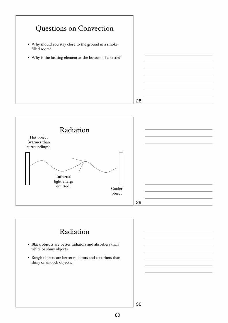
Questions on Convection
• Why should you stay close to the ground in a smoke-filled room?
• Why is the heating element at the bottom of a kettle?
Radiation
Infra-red light energy
emitted.. Cooler object
Hot object (warmer than surroundings).
Radiation• Black objects are better radiators and absorbers than
white or shiny objects.
• Rough objects are better radiators and absorbers than shiny or smooth objects.
28
29
30
80

Questions on Radiation
• Why are houses often painted white in hot countries?
• Why do marathon runners wear an aluminium blanket at the end of a race?
The Vacuum Flaskstopper
silver surface
vacuum
31
32
81

1
Thermal Physics Quantity and
symbol Definition Symbol equation units
Temperature, T, θ
The temperature of a gas is related to the motion of its particles. The faster, and therefore the more energetic the particles the hotter the gas.
oC, K
Brownian Motion
The random, jerky motion of particles (pollen in water, smoke in air) in a suspension is evidence for the kinetic model of matter. The massive particles are moved by light, fast moving molecules.
Evaporation
The more energetic molecules escape from the surface of a liquid. This leaves the liquid left behind with a lower average KE, and hence a cooler liquid.
Boyles’ Law For a fixed mass of gas, the pressure is inversely proportional to the volume, (at constant temperature)
P α 1 V PV = k
Charles’ Law For a fixed mass of gas, the volume is directly proportional to the temperature, (at constant pressure)
V α T V = k T
Pressure Law For a fixed mass of gas, the pressure is directly proportional to the temperature, (at constant volume)
P α T P = k T
Gas Law
For a fixed mass of gas, the Pressure x Volume = a constant
Temperature
PV = k T P1V1 = P2V2 T1 T2
Temperature must be the
absolute temperature in Kelvin,
K. The other quantities must be
consistent.
Thermal Capacity, c The amount of heat energy required to change the temperature of a body by 1 oC
c = E ΔT
J/ oC
Specific Heat Capacity, c
The amount of heat energy required to change the temperature of a unit mass of a substance by 1 oC
c = Q mΔT
J/kg oC Jkg oC
Latent Heat, L The amount of energy required to change the state of a body without a change in temperature
J
Specific Latent Heat of Fusion, L
The amount of energy required to change the state of unit mass of substance, from solid to liquid without a change in temperature
L = Q m
J/kg J/g
Specific Latent Heat of Vaporisation, L
The amount of energy required to change the state of unit mass of a substance from liquid to gas without a change in temperature
L = Q m
J/kg J/g
Conduction The movement of heat energy by the passing on of vibrations from particle to particle.
82

2
Convection The movement of heat energy by the mass movement of fluids, due to expansion and density changes due to heating.
Radiation The movement of heat energy by the form of an electromagnetic wave. (Infrared)
83

iGCSE PhysicsPast Paper QuestionsPaper 1 Compilation
Thermal Physics
84
7
0625/1/M/J/02 [Turn over
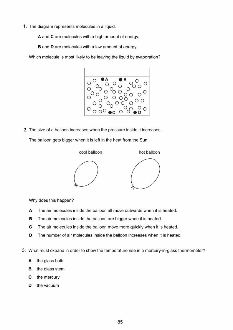
14 The diagram represents molecules in a liquid.
A and C are molecules with a high amount of energy.
B and D are molecules with a low amount of energy.
Which molecule is most likely to be leaving the liquid by evaporation?
15 The size of a balloon increases when the pressure inside it increases.
The balloon gets bigger when it is left in the heat from the Sun.
Why does this happen?
A The air molecules inside the balloon all move outwards when it is heated.
B The air molecules inside the balloon are bigger when it is heated.
C The air molecules inside the balloon move more quickly when it is heated.
D The number of air molecules inside the balloon increases when it is heated.
16 What must expand in order to show the temperature rise in a mercury-in-glass thermometer?
A the glass bulb
B the glass stem
C the mercury
D the vacuum
cool balloon hot balloon
A
C D
B
1.
2.
3.
85
8
0625/1/M/J/02
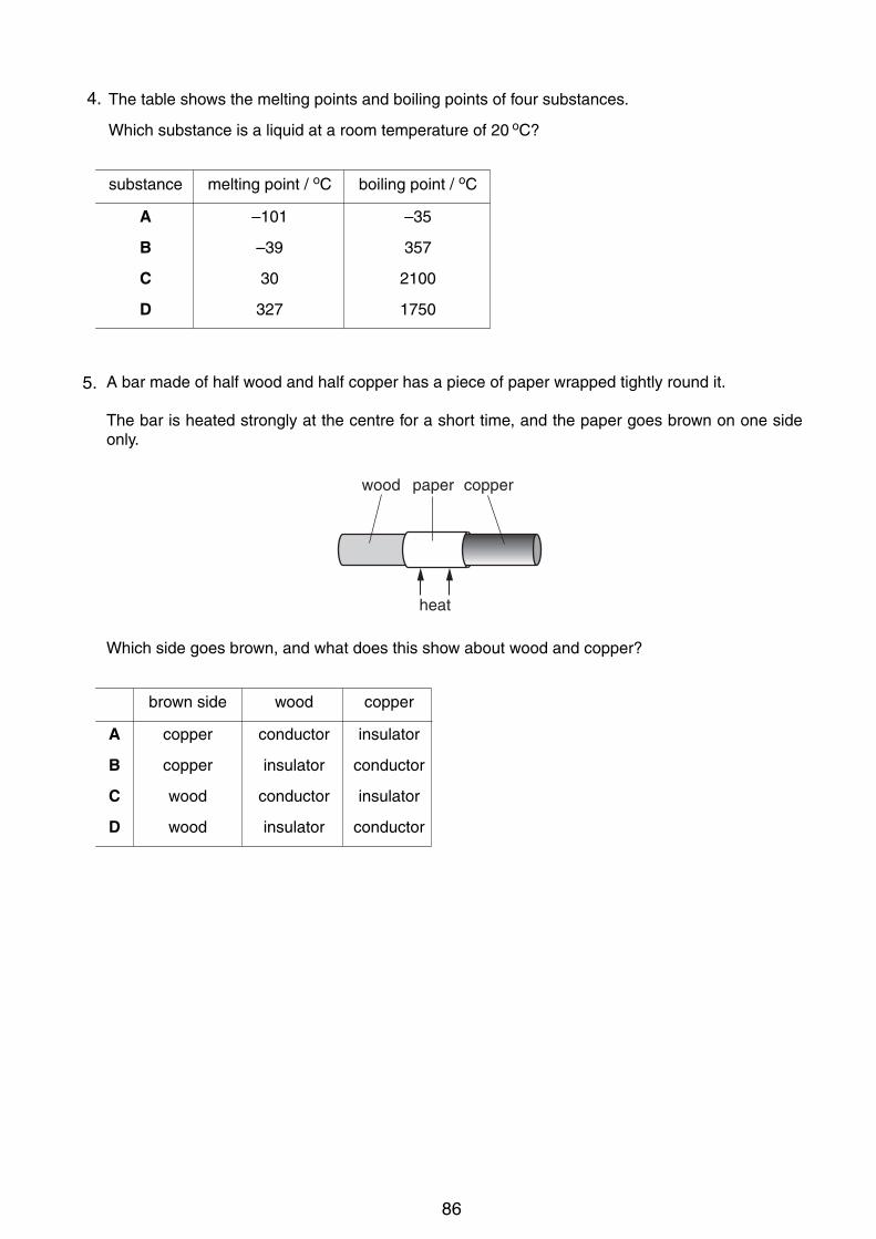
17 The table shows the melting points and boiling points of four substances.
Which substance is a liquid at a room temperature of 20 oC?
18 A bar made of half wood and half copper has a piece of paper wrapped tightly round it.
The bar is heated strongly at the centre for a short time, and the paper goes brown on one sideonly.
Which side goes brown, and what does this show about wood and copper?
wood paper copper
heat
substance melting point / oC boiling point / oC
A –101 –35
B –39 357
C 30 2100
D 327 1750
brown side wood copper
A copper conductor insulator
B copper insulator conductor
C wood conductor insulator
D wood insulator conductor
4.
5.
86

9
0625/1/M/J/02 [Turn over
19 The diagrams show part of a water-heating system which is working by convection.
Which diagram shows the most likely flow of water in the system?
20 A drop of water from a tap falls onto the surface of some water of constant depth.
Water waves spread out on the surface of the water.
Which statement is true?
A The waves are longitudinal and travel at the same speed in all directions.
B The waves are longitudinal and travel more quickly in one direction than in others.
C The waves are transverse and travel at the same speed in all directions.
D The waves are transverse and travel more quickly in one direction than in others.
view from above
hotwatertank
boiler
heat
A
hotwatertank
boiler
heat
B
hotwatertank
boiler
heat
C
hotwatertank
boiler
heat
D
9
0625/01/M/J/03 [Turn over
19 The diagram shows a heater used to heat a tank of cold water.
What is the main process by which heat moves through the water?
A conduction
B convection
C evaporation
D radiation
20 What causes refraction when light travels from air into glass?
A The amplitude of the light waves changes.
B The colour of the light changes.
C The frequency of the light waves changes.
D The speed of the light changes.
21 A woman tunes her radio to a station broadcasting on 200 m.
What does the 200m tell her about the radio wave?
A its amplitude
B its frequency
C its speed
D its wavelength
water
lagging
tank
heater
6.
7.
87

7
0625/01/M/J/03 [Turn over
15 Two metal boxes containing air are standing in a room. Box X is on top of a heater. Box Y is on abench. The boxes are left for a long time.
Which line in the table best describes the average speed of the molecules in the containers?
16 The top of the mercury thread in a mercury-in-glass thermometer reaches point X at 0 °C andpoint Z at 100 °C.
Where might it be at a temperature below the ice-point?
A point W
B point X
C point Y
D point Z
XW
ZY
X Y
heater bench
box X box Y
A fast zero
B fast slow
C slow fast
D zero fast
8.
9.
88
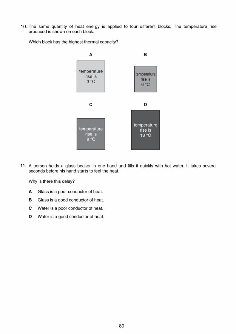
8
0625/01/M/J/03
17 The same quantity of heat energy is applied to four different blocks. The temperature riseproduced is shown on each block.
Which block has the highest thermal capacity?
18 A person holds a glass beaker in one hand and fills it quickly with hot water. It takes severalseconds before his hand starts to feel the heat.
Why is there this delay?
A Glass is a poor conductor of heat.
B Glass is a good conductor of heat.
C Water is a poor conductor of heat.
D Water is a good conductor of heat.
A B
C D
temperaturerise is3 °C
temperaturerise is9 °C
temperaturerise is18 °C
temperaturerise is6 °C
10.
11.
89

7
! UCLES 2004 0625/01/M/J/04 [Turn over
14 A student places his thumb firmly on the outlet of a bicycle pump, to stop the air coming out.
handle
trapped air
direction ofmotion
What happens to the pressure and to the volume of the trapped air as the pump handle is pushed
in?
pressure volume
A decreases decreases
B decreases remains the same
C increases decreases
D increases remains the same
15 A balloon is inflated in a cold room. When the room becomes much warmer, the balloon becomes
larger.
How does the behaviour of the air molecules in the balloon explain this?
A The molecules become larger.
B The molecules evaporate.
C The molecules move more quickly.
D The molecules repel each other.
9
© UCLES 2005 0625/01/M/J/05 [Turn over
19 The diagram shows a block of ice placed in a warm room.
At which point is the temperature the lowest?
!"#$%
&$"'()&%
!
"
#
$
20 The drawing shows a wave.
Which labelled distance is the wavelength?
AB
C
D
21 Radio waves are received at a house at the bottom of a hill.
hill
The waves reach the house because the hill has caused them to be
A diffracted.
B radiated.
C reflected.
D refracted.
A
CD
B
90

8
! U CLE S 2004 0625/01/M/J/04
16 A substance is heated at a steady rate. It changes from a solid to a liquid, and then to a gas.
The graph shows how its temperature changes with time.
temperature
time
P
Q
R
S
Which parts of the graph show a change of state taking place?
A P and R
B P and S
C Q and R
D Q and S
17 An engineer wants to fix a steel washer on to a steel rod. The rod is just too big to fit into the hole
of the washer.
steel rodsteelwasher
How can the engineer fit the washer onto the rod?
A cool the washer and put it over the rod
B cool the washer and rod to the same temperature and push them together
C heat the rod and then place it in the hole
D heat the washer and place it over the rod
5
© UCLES 2006 0625/01/M/J/06 [Turn over
11 The diagram shows a thick sheet of glass.
Which edge must it stand on to cause the greatest pressure?
A
D
C
B
12 A manometer is being used to measure the pressure of the gas inside a tank. A, B, C and D
show the manometer at different times.
At which time is the gas pressure inside the tank greatest?
gas
A B C D
13 Brownian motion is seen by looking at smoke particles through a microscope.
How do the smoke particles move in Brownian motion?
A all in the same direction
B at random
C in circles
D vibrating about fixed points
12.
13.
14.
91
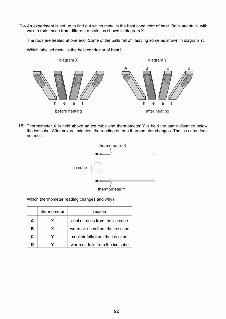
9
UCLES 2004 0625/01/M/J/04 [Turn over
18 An experiment is set up to find out which metal is the best conductor of heat. Balls are stuck with
wax to rods made from different metals, as shown in diagram X.
The rods are heated at one end. Some of the balls fall off, leaving some as shown in diagram Y.
Which labelled metal is the best conductor of heat?
before heating after heating
h e a t h e a t
diagram X diagram Y
A B C D
19 Thermometer X is held above an ice cube and thermometer Y is held the same distance below
the ice cube. After several minutes, the reading on one thermometer changes. The ice cube does
not melt.
ice cube
thermometer X
thermometer Y
Which thermometer reading changes and why?
thermometer reason
A X cool air rises from the ice cube
B X warm air rises from the ice cube
C Y cool air falls from the ice cube
D Y warm air falls from the ice cube
15.
16.
92

7
© UCLES 2005 0625/01/M/J/05 [Turn over
14 Viewed through a microscope, very small particles can be seen moving with Brownian motion.
Which line in the table is correct?
type of motion
of particles
particles are
suspended in
A vibration a liquid or a gas
B vibration a solid, a liquid or a gas
C random a liquid or a gas
D random a solid, a liquid or a gas
15 A measured mass of gas is placed in a cylinder at atmospheric pressure and is then slowly
compressed.
piston pushed in
pistongas
The temperature of the gas does not change.
What happens to the pressure of the gas?
A It drops to zero.
B It decreases, but not to zero.
C It stays the same.
D It increases.
16 The graph shows the change in temperature of a material as it is heated.
Which part on the graph shows when the material is boiling?
temperature
time
A
B
C
D
17.
18.
19.
93
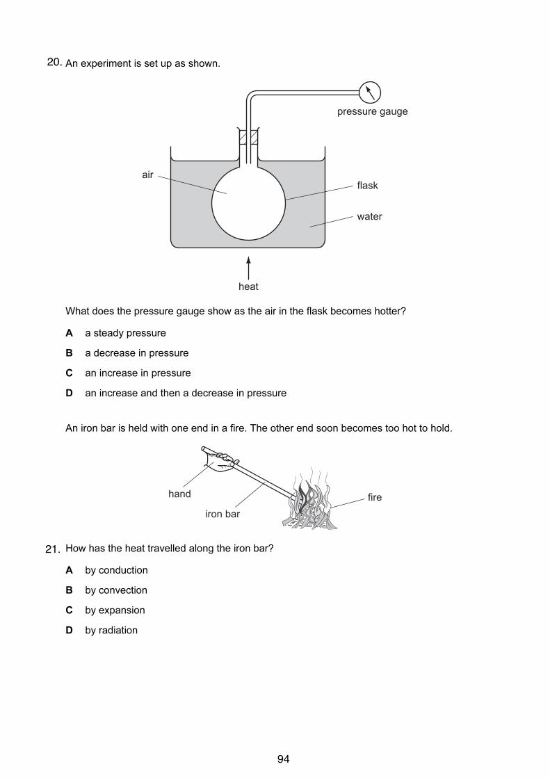
8
© UCLES 2005 0625/01/M/J/05
17 An experiment is set up as shown.
pressure gauge
flask
water
air
heat
What does the pressure gauge show as the air in the flask becomes hotter?
A a steady pressure
B a decrease in pressure
C an increase in pressure
D an increase and then a decrease in pressure
18 An iron bar is held with one end in a fire. The other end soon becomes too hot to hold.
firehand
iron bar
How has the heat travelled along the iron bar?
A by conduction
B by convection
C by expansion
D by radiation
20.
21.
94
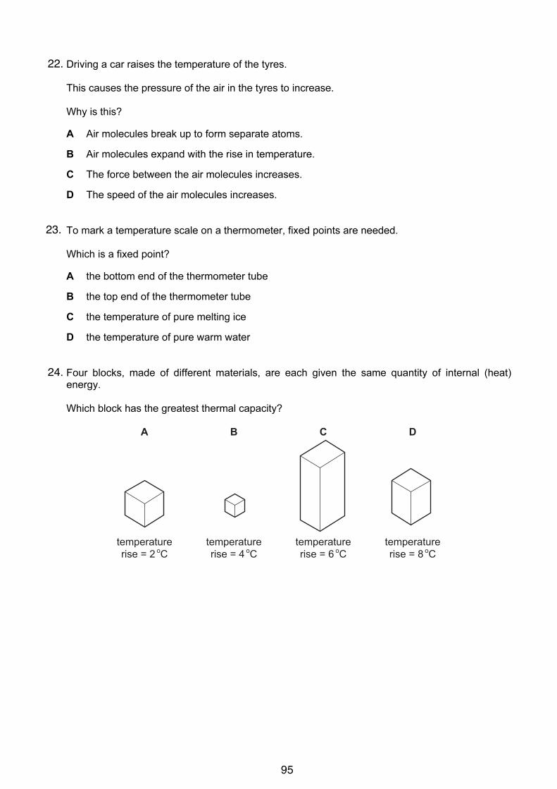
6
© UCLES 2006 0625/01/M/J/06
14 Driving a car raises the temperature of the tyres.
This causes the pressure of the air in the tyres to increase.
Why is this?
A Air molecules break up to form separate atoms.
B Air molecules expand with the rise in temperature.
C The force between the air molecules increases.
D The speed of the air molecules increases.
15 To mark a temperature scale on a thermometer, fixed points are needed.
Which is a fixed point?
A the bottom end of the thermometer tube
B the top end of the thermometer tube
C the temperature of pure melting ice
D the temperature of pure warm water
16 Four blocks, made of different materials, are each given the same quantity of internal (heat)
energy.
Which block has the greatest thermal capacity?
A
temperaturerise = 2 oC
B
temperaturerise = 4 oC
C
temperaturerise = 6 oC
D
temperaturerise = 8 oC
22.
23.
24.
95

7
© UCLES 2006 0625/01/M/J/06 [Turn over
17 A long thin bar of copper is heated evenly along its length.
copper bar
heat
What happens to the bar?
A It becomes lighter.
B It becomes longer.
C It becomes shorter.
D It bends at the ends.
18 A beaker contains water at room temperature.
X
Y
water
How could a convection current be set up in the water?
A cool the water at X
B cool the water at Y
C stir the water at X
D stir the water at Y
8
© UCLES 2006 0625/01/M/J/06
19 Two plastic cups are placed one inside the other. Hot water is poured into the inner cup and a lid
is put on top as shown.
lid
small spacer
small air gap
hot water
bench
Which statement is correct?
A Heat loss by radiation is prevented by the small air gap.
B No heat passes through the sides of either cup.
C The bench is heated by convection from the bottom of the outer cup.
D The lid is used to reduce heat loss by convection.
20 Which is the best description of the speed of a water wave?
A the distance between one wave crest and the next
B the distance between the crest of a wave and a trough
C the distance that a particle of water moves up and down in one second
D the distance that a wavefront moves along the surface in one second
25.
26.
27.
96

iGCSE Physics
Past Paper Questions
Paper 3 Compilation
Thermal Physics
97

5
0625/3/M/J/02 [Turn over
3 Fig. 3.1 is an attempt to show the molecules in water and the water vapour molecules overthe water surface.
Fig. 3.1
(a) Explain, in terms of the energies of the molecules, why only a few water molecules haveescaped from the water surface.
..........................................................................................................................................
..........................................................................................................................................
..................................................................................................................................... [2]
(b) State two ways of increasing the number of water molecules escaping from the surface.
1 .......................................................................................................................................
2 .................................................................................................................................. [2]
(c) Energy is required to evaporate water.
Explain, in molecular terms, why this energy is needed.
..........................................................................................................................................
..........................................................................................................................................
..................................................................................................................................... [2]
water vapourmolecules
water molecules
ForExaminer’s
Use1.
98
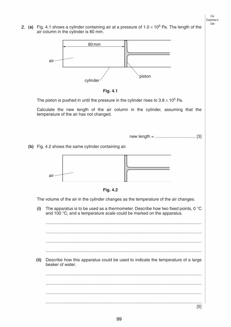
6
0625/3/M/J/02
4 (a) Fig. 4.1 shows a cylinder containing air at a pressure of 1.0 × 10⁵ Pa. The length of theair column in the cylinder is 80 mm.
Fig. 4.1
The piston is pushed in until the pressure in the cylinder rises to 3.8 × 10⁵ Pa.
Calculate the new length of the air column in the cylinder, assuming that thetemperature of the air has not changed.
new length = .................................. [3]
(b) Fig. 4.2 shows the same cylinder containing air.
Fig. 4.2
The volume of the air in the cylinder changes as the temperature of the air changes.
(i) The apparatus is to be used as a thermometer. Describe how two fixed points, 0 °Cand 100 °C, and a temperature scale could be marked on the apparatus.
...................................................................................................................................
...................................................................................................................................
...................................................................................................................................
...................................................................................................................................
(ii) Describe how this apparatus could be used to indicate the temperature of a largebeaker of water.
...................................................................................................................................
...................................................................................................................................
...................................................................................................................................
...................................................................................................................................[5]
air
80mm
air
cylinderpiston
ForExaminer’s
Use2.
99

5
0625/3/M/J/03 [Turn over
(b) Another box of weight 1500 N is raised vertically by 3.0 m.
(i) Calculate the work done on the box.
work done = ..................................
(ii) The crane takes 2.5 s to raise this box 3.0 m. Calculate the power output of thecrane.
power = ..................................[4]
4 Fig. 4.1 shows a sealed glass syringe that contains air and many very tiny suspended dustparticles.
Fig. 4.1
(a) Explain why the dust particles are suspended in the air and do not settle to the bottom.
..........................................................................................................................................
..........................................................................................................................................
..........................................................................................................................................
......................................................................................................................................[3]
(b) The air in the syringe is at a pressure of 2.0 ! 105 Pa. The piston is slowly moved into thesyringe, keeping the temperature constant, until the volume of the air is reduced from80 cm3 to 25 cm3. Calculate the final pressure of the air.
pressure = ..................................[3]
syringe
seal
dust particles
piston
ForExaminer’s
Use
5
0625/3/M/J/03 [Turn over
(b) Another box of weight 1500 N is raised vertically by 3.0 m.
(i) Calculate the work done on the box.
work done = ..................................
(ii) The crane takes 2.5 s to raise this box 3.0 m. Calculate the power output of thecrane.
power = ..................................[4]
4 Fig. 4.1 shows a sealed glass syringe that contains air and many very tiny suspended dustparticles.
Fig. 4.1
(a) Explain why the dust particles are suspended in the air and do not settle to the bottom.
..........................................................................................................................................
..........................................................................................................................................
..........................................................................................................................................
......................................................................................................................................[3]
(b) The air in the syringe is at a pressure of 2.0! 105 Pa. The piston is slowly moved into thesyringe, keeping the temperature constant, until the volume of the air is reduced from80 cm3 to 25 cm3. Calculate the final pressure of the air.
pressure = ..................................[3]
syringe
seal
dust particles
piston
For
Examiner’s
Use
3.
100
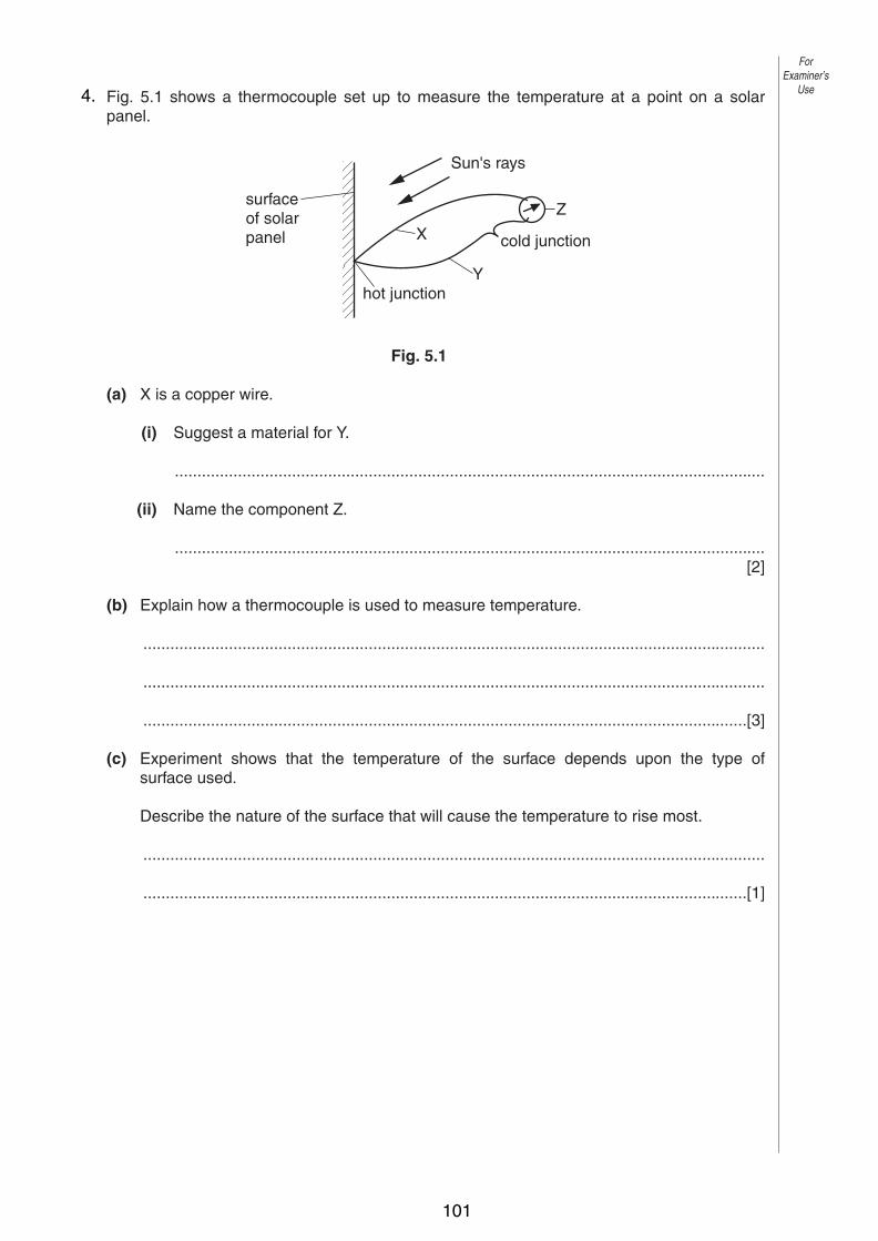
6
0625/3/M/J/03
5 Fig. 5.1 shows a thermocouple set up to measure the temperature at a point on a solarpanel.
Fig. 5.1
(a) X is a copper wire.
(i) Suggest a material for Y.
...................................................................................................................................
(ii) Name the component Z.
...................................................................................................................................[2]
(b) Explain how a thermocouple is used to measure temperature.
..........................................................................................................................................
..........................................................................................................................................
......................................................................................................................................[3]
(c) Experiment shows that the temperature of the surface depends upon the type ofsurface used.
Describe the nature of the surface that will cause the temperature to rise most.
..........................................................................................................................................
......................................................................................................................................[1]
cold junction
Y
Z
X
hot junction
Sun's rays
surfaceof solarpanel
ForExaminer’s
Use4.
101

6
0625/03 M/J/04
4 (a) Two identical open boxes originally contain the same volume of water.One is kept at 15 °C and the other at 85 °C for the same length of time.
Fig. 4.1 shows the final water levels.
Fig. 4.1
With reference to the energies of the water molecules, explain why the levels aredifferent.
..........................................................................................................................................
..........................................................................................................................................
..........................................................................................................................................
......................................................................................................................................[3]
(b) In an experiment to find the specific latent heat of vaporisation of water, it took 34 500 Jof energy to evaporate 15 g of water that was originally at 100 °C.
A second experiment showed that 600 J of energy was lost to the atmosphere from theapparatus during the time it took to evaporate 15 g of water.
Calculate the specific latent heat of vaporisation of water that would be obtained fromthis experiment.
specific latent heat = …………………[3]
85 °C15 °C
ForExaminer’s
Use
© UCLES 2004
5.
102
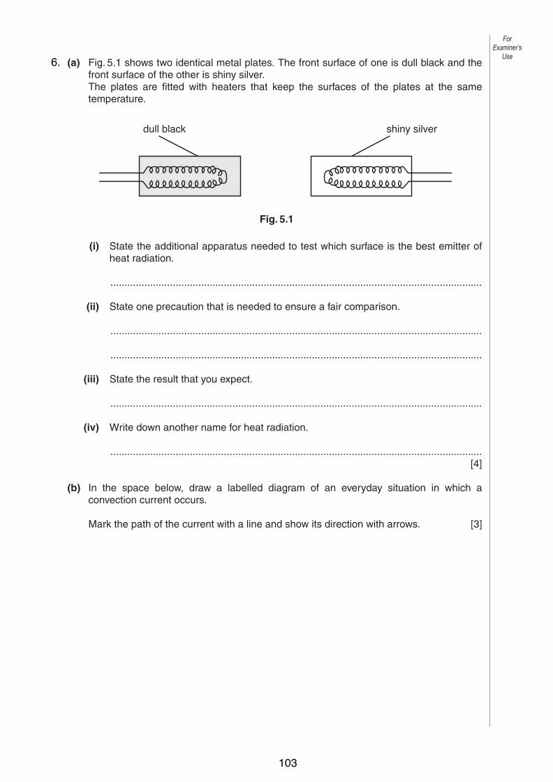
7
0625/03 M/J/04 [Turn over
5 (a) Fig. 5.1 shows two identical metal plates. The front surface of one is dull black and thefront surface of the other is shiny silver.The plates are fitted with heaters that keep the surfaces of the plates at the sametemperature.
Fig. 5.1
(i) State the additional apparatus needed to test which surface is the best emitter ofheat radiation.
...................................................................................................................................
(ii) State one precaution that is needed to ensure a fair comparison.
...................................................................................................................................
...................................................................................................................................
(iii) State the result that you expect.
...................................................................................................................................
(iv) Write down another name for heat radiation.
...................................................................................................................................[4]
(b) In the space below, draw a labelled diagram of an everyday situation in which aconvection current occurs.
Mark the path of the current with a line and show its direction with arrows. [3]
dull black shiny silver
ForExaminer’s
Use
© UCLES 2004
6.
103

6
0625/03/M/J/05
4 Fig. 4.1 shows apparatus that a student uses to make an estimate of the specific heatcapacity of iron.
Fig. 4.1
(a) The power of the heater is known. State the four readings the student must take to findthe specific heat capacity of iron.
1. ......................................................................................................................................
2. ......................................................................................................................................
3. ......................................................................................................................................
4. ................................................................................................................................. [3]
(b) Write down an equation, in words or in symbols, that could be used to work out thespecific heat capacity of iron from the readings in (a).
[2]
iron block
electrical heaterthermometer
ForExaminer’s
Use
© UCLES 2005
7.
104

7
0625/03/M/J/05 [Turn over
(c) (i) Explain why the value obtained with this apparatus is higher than the actual value.
...................................................................................................................................
.............................................................................................................................. [1]
(ii) State one addition to the apparatus that would help to improve the accuracy of thevalue obtained.
...................................................................................................................................
.............................................................................................................................. [1]
ForExaminer’s
Use
© UCLES 2005
105

8
0625/03/M/J/05
5 (a) Fig. 5.1 shows the paths of a few air molecules and a single dust particle. The actual airmolecules are too small to show on the diagram.
Fig. 5.1
Explain why the dust particle undergoes small random movements.
..........................................................................................................................................
..........................................................................................................................................
..........................................................................................................................................
..................................................................................................................................... [4]
(b) Fig. 5.2 shows the paths of a few molecules leaving the surface of a liquid. The liquid isbelow its boiling point.
Fig. 5.2
(i) State which liquid molecules are most likely to leave the surface.
...................................................................................................................................
.............................................................................................................................. [1]
(ii) Explain your answer to (i).
...................................................................................................................................
...................................................................................................................................
.............................................................................................................................. [2]
air and vapourliquid
dust particle
paths ofair molecules
ForExaminer’s
Use
© UCLES 2005
8.
106
5
0625/03/M/J/06 [Turn over
ForExaminer’s
Use
© UCLES 2006
4 (a) State two differences between evaporation of water and boiling of water.
1. ......................................................................................................................................
2. ..................................................................................................................................[2]
(b) The specific latent heat of vaporisation of water is 2260 kJ / kg. Explain why this energy is needed to boil water and why the temperature of the water
does not change during the boiling.
..........................................................................................................................................
..........................................................................................................................................
..........................................................................................................................................
......................................................................................................................................[3]
(c) A laboratory determination of the specific latent heat of vaporisation of water uses a 120 W heater to keep water boiling at its boiling point. Water is turned into steam at the rate of 0.050 g / s.
Calculate the value of the specific latent heat of vaporisation obtained from this experiment. Show your working.
specific latent heat of vaporisation = ........................[3]
9.
107

6
0625/03/M/J/06
ForExaminer’s
Use
© UCLES 2006
5 (a) Fig. 5.1 shows a tank used for evaporating salt solution to produce crystals.
salt solution
evaporating tank
steam out
steam in
Fig. 5.1
Suggest two ways of increasing the rate of evaporation of the water from the solution. Changes may be made to the apparatus, but the rate of steam supply must stay constant.
You may assume the temperature of the salt solution remains constant.
1. ......................................................................................................................................
..........................................................................................................................................
2. ......................................................................................................................................
......................................................................................................................................[2]
(b) A manufacturer of liquid-in-glass thermometers changes the design in order to meet new requirements.
Describe the changes that could be made to
(i) give the thermometer a greater range,
..............................................................................................................................[1]
(ii) make the thermometer more sensitive.
..............................................................................................................................[1]
(c) A toilet flush is operated by the compression of air. The air inside the flush has a pressure of 1.0 × 10⁵ Pa and a volume of 150 cm3. When the flush is operated the volume is reduced to 50 cm3. The temperature of the air remains constant during this process.
Calculate the new pressure of the air inside the flush.
pressure = .......................[2]
10.
108

Topic 3:Waves
Transverse Waves
Wavelength
Wavelength
amplitude
amplitude
Frequency=Number of Waves per second (Hz)
Types of Waves
• Waves carry energy without matter being transferred.
• There are two types of wave motion:
• Transverse.
• Longitudinal.
1
2
3
109

Transverse Waves
• In a transverse wave, the wave motion is at right angles to the direction of the wave.
• The Energy flows in a direction at right angles to the wave motion.
• Examples of transverse waves are Light, Pond-ripples, Seismic S-waves.
Longitudinal Waves
In a longitudinal wave, the wave motion is along the direction of the wave. It consists of a series of compressions and rarefractions.
The Energy flows in the same direction as the wave motion.
Examples of longitudinal waves are Sound and Seismic P-waves.
Reflection• If waves hit a boundary, they will reflect.
• The angle of incidence will be equal to the angle of reflection.
Incident wavefronts
Reflected wavefronts
Reflecting Surface
Normal
4
5
6
110
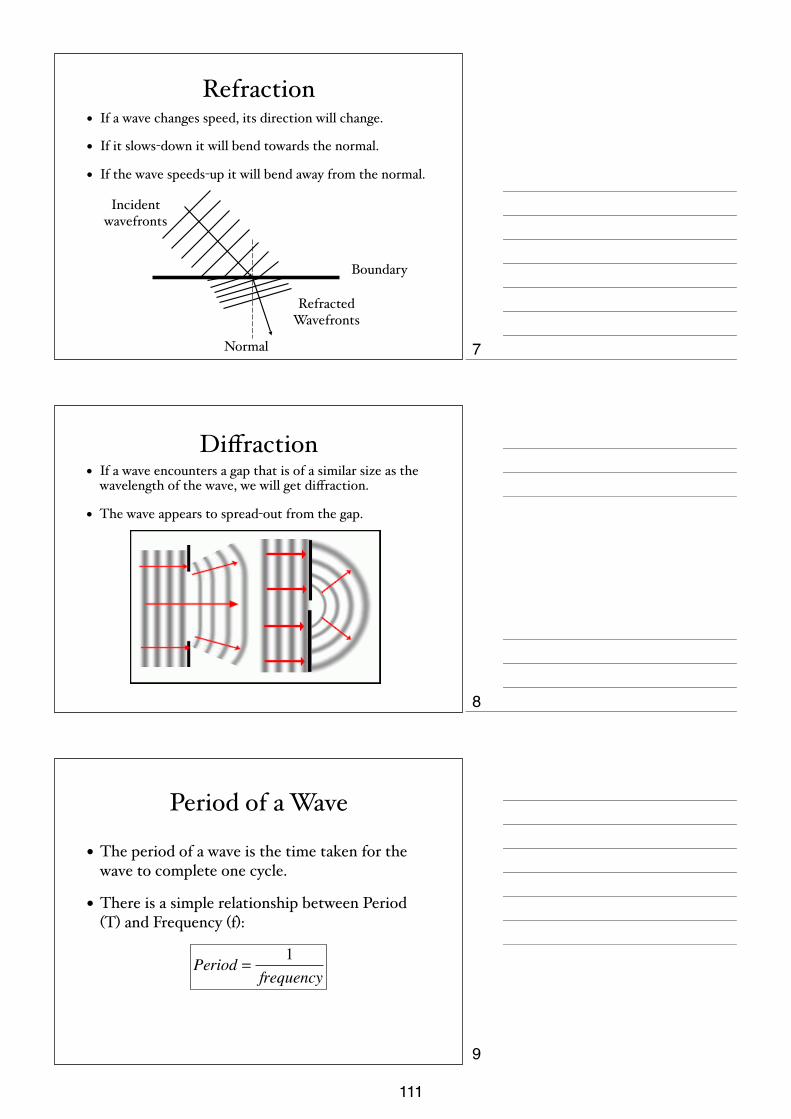
Refraction• If a wave changes speed, its direction will change.
• If it slows-down it will bend towards the normal.
• If the wave speeds-up it will bend away from the normal.
Boundary
Normal
Incident wavefronts
Refracted Wavefronts
Diffraction• If a wave encounters a gap that is of a similar size as the
wavelength of the wave, we will get diffraction.
• The wave appears to spread-out from the gap.
Period of a Wave
• The period of a wave is the time taken for the wave to complete one cycle.
• There is a simple relationship between Period (T) and Frequency (f):
Period =1
frequency
7
8
9
111

The Wave Equation
• The wave-speed (v), the frequency (f) and the wavelength (λ) are linked with the wave equation:
v(m s) = f (Hz)λ(m)
Wave Equation Questions1. The speed of sound in air is 340m/s. A musical note has a wavelength of 0.6m. Calculate the frequency of the note.
2. In a concert hall, an echo is heard 0.5s after the note was played. How long is the hall?
3 The speed of light in air is 300 000 000 m/s. The frequency of the “Radio Uno” radio station is 567 kHz. Calculate the wavelength of the radio waves.
4 What would be the Period of one these waves?
Reflection in a Plane Mirror• In a plane mirror, angle of incidence=angle of reflection.
• The mirror produces a virtual upright image behind the mirror, the same size as the object and at the same distance as the object.
• The image is laterality inverted.
Eye
ImageObject
10
11
12
112
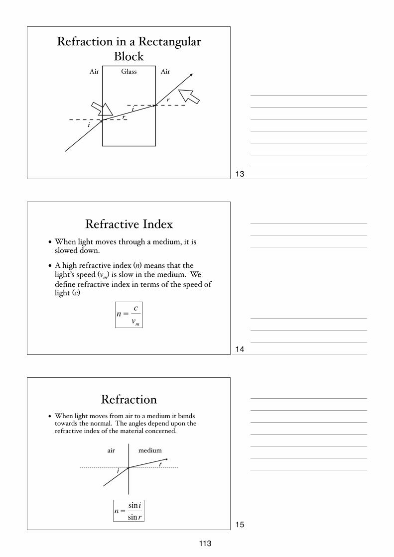
Refraction in a Rectangular Block
Air AirGlass
i
ir
r
Refractive Index• When light moves through a medium, it is
slowed down.
• A high refractive index (n) means that the light’s speed (vm) is slow in the medium. We define refractive index in terms of the speed of light (c)
n =cvm
Refraction• When light moves from air to a medium it bends
towards the normal. The angles depend upon the refractive index of the material concerned.
ir
air medium
n =sin isin r
13
14
15
113

Spectrum of Visible Light• The colours of visible light can be arranged
according to their wavelength.
• We normally say that there are seven distinct colours, although the spectrum is continuous.
• In order of increasing wavelength, the colours are:
• Red, Orange, Yellow, Green, Blue, Indigo & Violet.
• Each colour of light refracts by a different amount; violet light the most, red light the least.
prism
White light
screen
Dispersion
Refraction
Refraction in a Semi-Circular Block
Critical Angle
Total Internal
Reflection
C i ri
r
16
17
18
114

Total Internal Reflection• If the angle of Incidence is greater than the Critical
angle then the light undergoes TOTAL INTERNAL REFLECTION.
• All of the energy stays inside the block.
Optical Fibres
Optical Fibre
Refracting Periscope
19
20
21
115

Keyhole Surgery
A camera and remote-controlled surgical instruments are inserted
into a small incision in the patient.
There is less risk of infection and a quicker recovery time than
invasive surgery.
Fibre Optic Transmission
Signals are sent as pulses of light.
Cheaper signal production, less signal boosting, more secure transmission, higher bandwidth (more information
possible).
Converging Lens
• A convex (converging) lens is wider in the middle than at the edges.
• Convex lenses have a principal focus on either side.
• The distance between the lens and the focus is called the “focal length”
focus focus
focallength
focallength
22
23
24
116
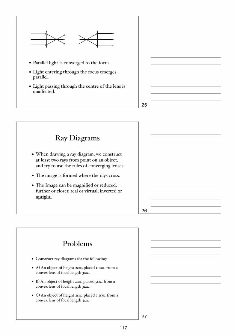
• Parallel light is converged to the focus.
• Light entering through the focus emerges parallel.
• Light passing through the centre of the lens is unaffected.
Ray Diagrams
• When drawing a ray diagram, we construct at least two rays from point on an object, and try to use the rules of converging lenses.
• The image is formed where the rays cross.
• The Image can be magnified or reduced, further or closer, real or virtual, inverted or upright.
Problems
• Construct ray diagrams for the following:
• A) An object of height 2cm placed 10cm from a convex lens of focal length 3cm.
• B) An object of height 2cm placed 5cm from a convex lens of focal length 3cm.
• C) An object of height 2cm placed 2.5cm from a convex lens of focal length 3cm.
25
26
27
117

Radio Waves
Infra-red Waves Visible
Ultra-violet Rays
X-Rays Gamma Rays
Micro Waves
The Electromagnetic SpectrumLong Wavelength
Low Frequency
Short Wavelength
High Frequency
Sound• Sounds are produced when objects VIBRATE.
• Sound is a LONGITUDINAL wave.
• Reflected sound waves produce echoes.
• Sound travels at about 340 m/s in air. It travels faster in liquids and faster still in solids.
• Unlike light, sound needs a medium.
• Sound waves can be displayed electronically using an Oscilloscope.
• The greater the amplitude, the louder the sound.
• The greater the frequency, the higher the pitch.
• Our ears are sensitive to sound in the range 20 Hz - 20 kHz.
• Ultrasound is of a higher frequency than our ears can detect. (pre-natal scans, sonar)
Sound Waves
Low Frequency (Low pitch) and Large Amplitude (Loud)
Low Frequency (Low pitch) and Small Amplitude (Quiet)
High Frequency (High pitch) and Large Amplitude (Loud)
High Frequency (High pitch) and Small Amplitude (Quiet)
28
29
30
118
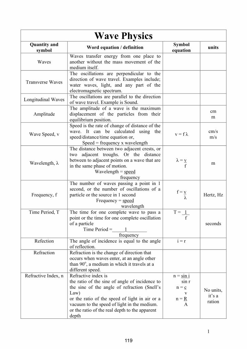
1
Wave Physics Quantity and
symbol Word equation / definition Symbol equation units
Waves Waves transfer energy from one place to another without the mass movement of the medium itself.
Transverse Waves
The oscillations are perpendicular to the direction of wave travel. Examples include; water waves, light, and any part of the electromagnetic spectrum.
Longitudinal Waves The oscillations are parallel to the direction of wave travel. Example is Sound.
Amplitude The amplitude of a wave is the maximum displacement of the particles from their equilibrium position.
cm m
Wave Speed, v
Speed is the rate of change of distance of the wave. It can be calculated using the speed/distance/time equation or,
Speed = frequency x wavelength
v = f λ cm/s m/s
Wavelength, λ
The distance between two adjacent crests, or two adjacent troughs. Or the distance between to adjacent points on a wave that are in the same phase of motion.
Wavelength = speed frequency
λ = v f m
Frequency, f
The number of waves passing a point in 1 second, or the number of oscillations of a particle or the source in 1 second
Frequency = speed wavelength
f = v λ Hertz, Hz
Time Period, T The time for one complete wave to pass a point or the time for one complete oscillation of a particle
Time Period =_____1________ frequency
T = _1_ f
seconds
Refection The angle of incidence is equal to the angle of reflection.
i = r
Refraction Refraction is the change of direction that occurs when waves enter, at an angle other than 90o, a medium in which it travels at a different speed.
Refractive Index, n Refractive index is the ratio of the sine of angle of incidence to the sine of the angle of refraction (Snell’s Law) or the ratio of the speed of light in air or a vacuum to the speed of light in the medium. or the ratio of the real depth to the apparent depth
n = sin i sin r
n = c v n = R A
No units, it’s a ration
119
2
Critical Angle, C The Critical Angle occurs inside the more dense medium and is the angle of incidence, at which the angle of refraction is 90o, i.e. along the boundary between the mediums
n = ___1___ sin C
Total Internal Reflection
Total internal reflection occurs at angles greater than the critical angle inside a more dense medium.
Diffraction Diffraction is the spreading out of waves as they pass through a gap. The narrower the gap the more diffraction there is.
Dispersion Dispersion is the splitting of light into the colours of the spectrum, due to the different speeds at which these colours travel in the prism.
Speed of Light And all other waves in the electromagnet spectrum
3.0 x10⁸ m/s
Monochromatic Monochromatic means of one frequency. Therefore if monochromatic light is passed through a triangular prism dispersion will not occur.
Speed of Sound 330 m/s
120
iGCSE PhysicsPast Paper QuestionsPaper 1 Compilation
Waves
121

9
0625/1/M/J/02 [Turn over
19 The diagrams show part of a water-heating system which is working by convection.
Which diagram shows the most likely flow of water in the system?
20 A drop of water from a tap falls onto the surface of some water of constant depth.
Water waves spread out on the surface of the water.
Which statement is true?
A The waves are longitudinal and travel at the same speed in all directions.
B The waves are longitudinal and travel more quickly in one direction than in others.
C The waves are transverse and travel at the same speed in all directions.
D The waves are transverse and travel more quickly in one direction than in others.
view from above
hotwatertank
boiler
heat
A
hotwatertank
boiler
heat
B
hotwatertank
boiler
heat
C
hotwatertank
boiler
heat
D
9
0625/1/M/J/02 [Turn over
19 The diagrams show part of a water-heating system which is working by convection.
Which diagram shows the most likely flow of water in the system?
20 A drop of water from a tap falls onto the surface of some water of constant depth.
Water waves spread out on the surface of the water.
Which statement is true?
A The waves are longitudinal and travel at the same speed in all directions.
B The waves are longitudinal and travel more quickly in one direction than in others.
C The waves are transverse and travel at the same speed in all directions.
D The waves are transverse and travel more quickly in one direction than in others.
view from above
hotwatertank
boiler
heat
A
hotwatertank
boiler
heat
B
hotwatertank
boiler
heat
C
hotwatertank
boiler
heat
D
12
0625/1/M/J/02
25 A girl stands in front of a rock face.
The girl claps her hands once. The speed of sound in air is 330 m / s.
How long is it before she hears the echo?
A s B s C s D s
26 Which diagram best shows the pattern of field lines around a bar magnet?
N S
A B
N S
N S
C D
N S
330______2 x 660
330___660
660___330
2 x 660______330
660 m
rock face
1.
2.
122

10
0625/1/M/J/02
21 A student measures how far a cork moves up and down on a wave in a tank of water.
Which quantity can he obtain from his measurement?
A amplitude
B frequency
C speed
D wavelength
22 Alpha-particles, beta-particles, gamma-rays and infra-red radiation may all be emitted from asolid.
Which of these are included in the electromagnetic spectrum?
A alpha-particles and beta-particles
B alpha-particles and gamma-rays
C beta-particles and infra-red radiation
D gamma-rays and infra-red radiation
ruler
cork
directionof wave
3.
4.
123

11
0625/1/M/J/02 [Turn over
23 The image of a clock face as seen in a plane mirror is shown.
What is the actual time on the clock?
A 1.25 B 1.35 C 10.25 D 10.35
24 Four sound waves W, X, Y and Z are displayed by an oscilloscope screen. The oscilloscopesettings are the same in each case.
Which two sounds have the same pitch?
A W and X
B W and Y
C X and Y
D X and Z
W X
Y Z
12
6
93
5.
6.
124

10
0625/01/M/J/03
22 Which statement is correct about the speed of electromagnetic waves in a vacuum?
A Ultra-violet waves have the greatest speed.
B Visible light waves have the greatest speed.
C Infra-red waves have the greatest speed.
D All electromagnetic waves have the same speed.
23 Which diagram correctly shows rays passing through a camera lens?
camera
film
imagelens
object
A
camera
film
imagelens
object
C
camera
film
imagelens
object
B
camera
film
imagelens
object
D
7.
125
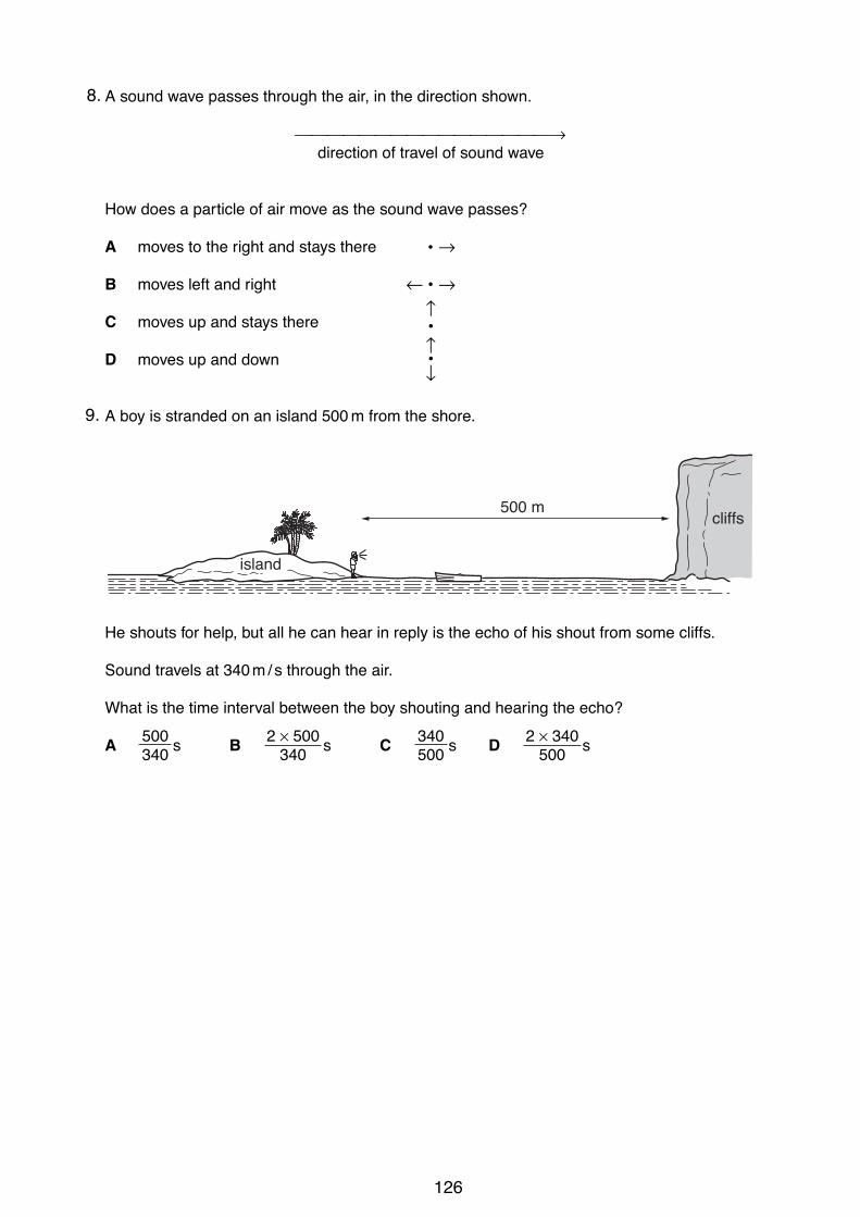
11
0625/01/M/J/03 [Turn over
24 A sound wave passes through the air, in the direction shown.
!!!!!!!!!!!!!!!!"direction of travel of sound wave
How does a particle of air move as the sound wave passes?
A moves to the right and stays there • "
B moves left and right # • "
C moves up and stays there
D moves up and down
25 A boy is stranded on an island 500 m from the shore.
He shouts for help, but all he can hear in reply is the echo of his shout from some cliffs.
Sound travels at 340m/s through the air.
What is the time interval between the boy shouting and hearing the echo?
A s B s C s D s2 $ 340500
340500
2 $ 500340
500340
island
cliffs500 m
%•&
%•
8.
9.
126
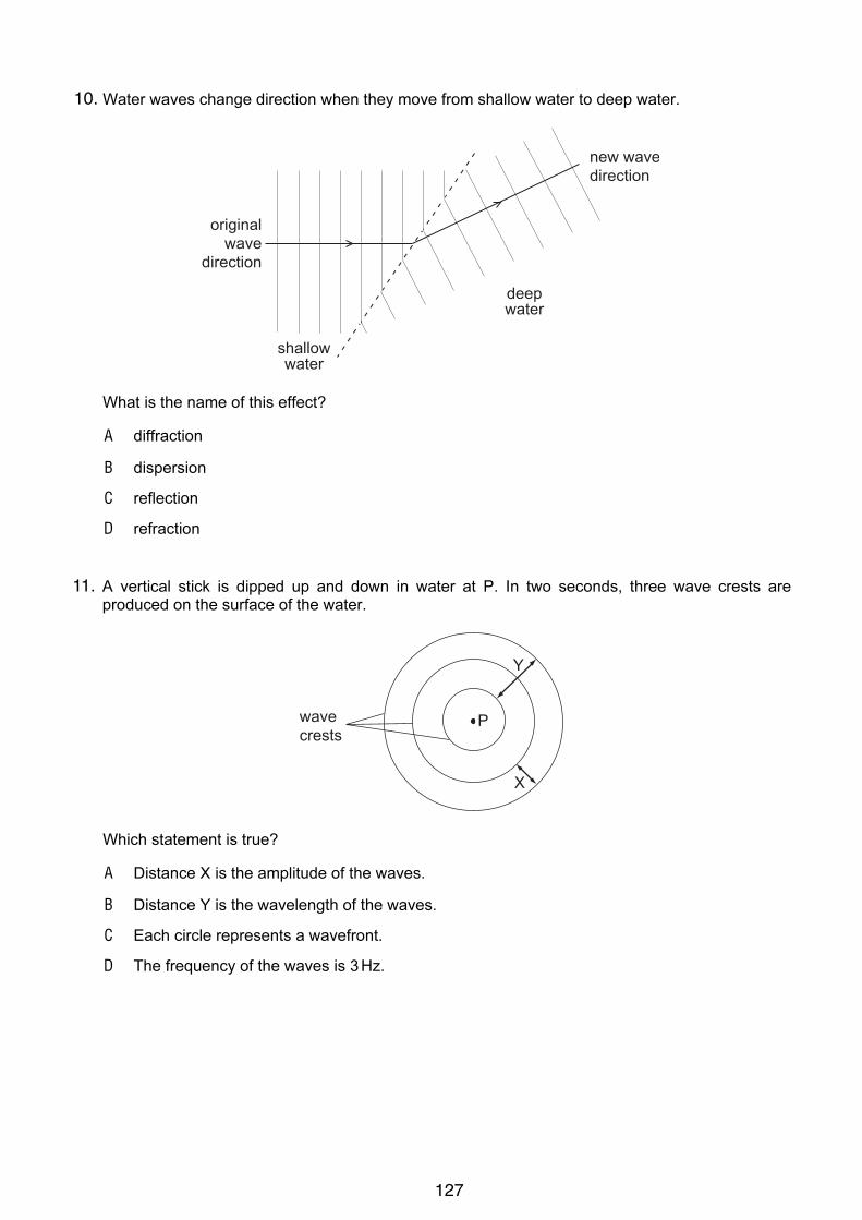
10
! UCLES 2004 0625/01/M/J/04
20 Water waves change direction when they move from shallow water to deep water.
shallowwater
deepwater
originalwave
direction
new wavedirection
What is the name of this effect?
A diffraction
B dispersion
C reflection
D refraction
21 A vertical stick is dipped up and down in water at P. In two seconds, three wave crests are
produced on the surface of the water.
P
X
Y
wavecrests
Which statement is true?
A Distance X is the amplitude of the waves.
B Distance Y is the wavelength of the waves.
C Each circle represents a wavefront.
D The frequency of the waves is 3Hz.
10.
11.
127

11
! UCLES 2004 0625/01/M/J/04 [Turn over
22 A plane mirror is on a wall.
Which is a correct description of the image formed by the mirror?
A the right way up and smaller than the object
B the right way up and the same size as the object
C upside down and smaller than the object
D upside down and the same size as the object
23 The diagram shows a ray of light entering a block of glass.
12
3
4
normal
air
glass
ray oflight
Which numbered angles are the angles of incidence and of refraction?
angle
of incidence
angle
of refraction
A 1 3
B 1 4
C 2 3
D 2 4
12.
13.
128
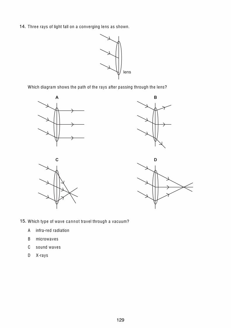
12
U CLE S 2004 0625/01/M/J/04
24 Three rays of light fa ll on a converging lens as shown.
lens
Which diagram shows the pa th of the rays a fter passing through the lens?
A B
C D
25 Which type of wave c a n n o t trave l through a vacuum?
A infra-red radia tion
B microwaves
C sound waves
D X-rays
14.
15.
129

13
! UCLES 2004 0625/01/M/J/04 [Turn over
26 An engineer standing at P hears the sound of an explosion at X.
Z
YX
WV
P
DANGER - BLASTING
After the explosion, she hears two bangs. One bang is heard a fraction of a second after the
other.
The second bang is an echo from
A XY.
B PV.
C ZY.
D WX.
27 How can a permanent magnet be demagnetised?
A cool the magnet for a long time
B hit the magnet repeatedly with a hammer
C leave the magnet in a coil which carries direct current
D pass a small current through the magnet
28 An electromagnet is used to separate magnetic metals from non-magnetic metals.
Why is steel unsuitable as the core of the electromagnet?
A It is a good conductor of electricity.
B It forms a permanent magnet.
C It has a high density.
D It has a high thermal capacity.
9
© U CLE S 2005 0625/01/M/J/05 [Turn over
19 The diagram shows a block of ice placed in a warm room.
A t which point is the tempera ture the lowest?
table
clampice
!
"
#
$
20 The drawing shows a wave .
Which labe lled distance is the wave length?
A
B
C
D
21 Radio waves are rece ived a t a house a t the bottom of a hill.
hill
The waves reach the house because the hill has caused them to be
A diffracted.
B radia ted.
C re flected.
D re fracted.
16.
17.
130

10
© UCLES 2005 0625/01/M/J/05
22 Which diagram correctly shows a ray of light passing through a rectangular glass block?
A B
C D
23 The ray diagram shows how an image is formed by a converging lens.
24 cm 10 cm 8 cm
What is the focal length of this lens?
A 8 cm B 10 cm C 18 cm D 24 cm
9
© UCLES 2005 0625/01/M/J/05 [Turn over
19 The diagram shows a block of ice placed in a warm room.
At which point is the temperature the lowest?
table
clampice
!
"
#
$
20 The drawing shows a wave.
Which labelled distance is the wavelength?
A
B
C
D
21 Radio waves are received at a house at the bottom of a hill.
hill
The waves reach the house because the hill has caused them to be
A diffracted.
B radiated.
C reflected.
D refracted.
18.
19.
20.
131
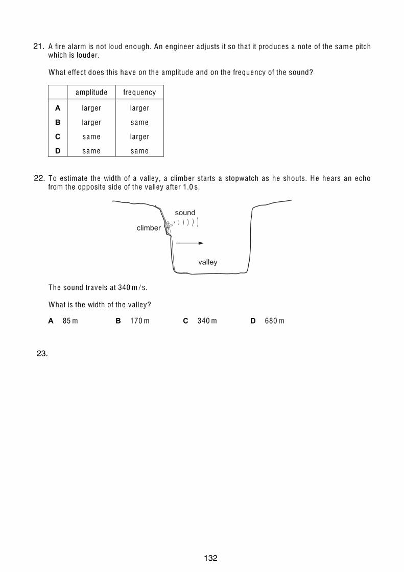
11
© UCLES 2005 0625/01/M/J/05 [Turn over
24 A fire a larm is not loud enough. An engineer adjusts it so tha t it produces a note of the same pitch which is louder.
Wha t e ffect does this have on the amplitude and on the frequency of the sound?
amplitude frequency
A larger larger
B larger same
C same larger
D same same 25 To estima te the width of a va lley, a climber starts a stopwa tch as he shouts. He hears an echo
from the opposite side of the va lley a fter 1.0 s.
valley
sound
climber
The sound trave ls a t 340 m / s.
Wha t is the width of the va lley?
A 85 m B 170 m C 340 m D 680 m 26 Which ma teria l is used for the core of an e lectromagne t?
A a luminium
B copper
C iron
D stee l
8
© U CLE S 2006 0625/01/M/J/06
19 Two plastic cups are placed one inside the other. Hot wa ter is poured into the inner cup and a lid is put on top as shown.
lid
small spacer
small air gap
hot water
bench
Which sta tement is correct?
A Hea t loss by radia tion is prevented by the sma ll a ir gap.
B No hea t passes through the sides of e ither cup.
C The bench is hea ted by convection from the bottom of the outer cup.
D The lid is used to reduce hea t loss by convection. 20 Which is the best description of the speed of a wa ter wave?
A the distance be tween one wave crest and the next
B the distance be tween the crest of a wave and a trough
C the distance tha t a particle of wa ter moves up and down in one second
D the distance tha t a wave front moves a long the surface in one second
21.
22.
23.
132
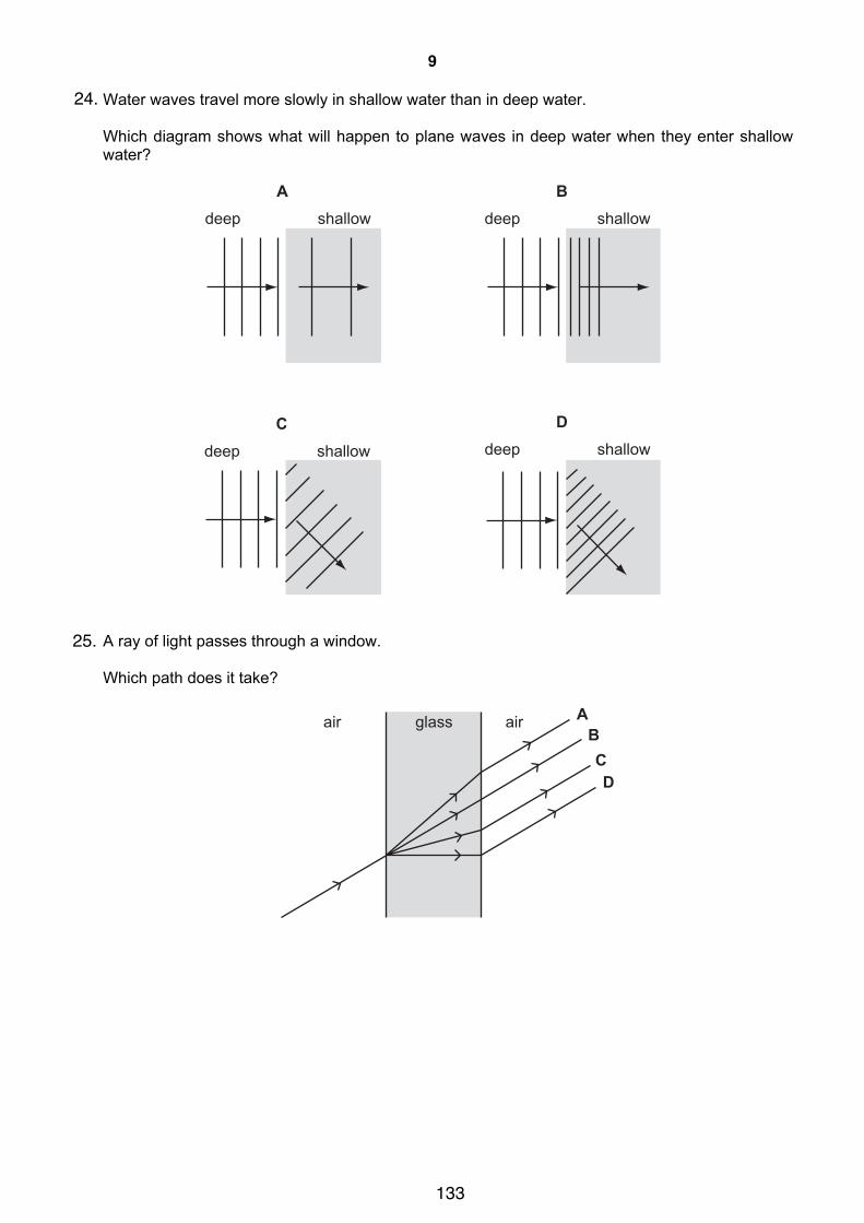
9
© UCLES 2006 0625/01/M/J/06 [Turn over
21 Water waves travel more slowly in shallow water than in deep water.
Which diagram shows what will happen to plane waves in deep water when they enter shallow
water?
Adeep shallow
Bdeep shallow
Ddeep shallow
Cdeep shallow
22 A ray of light passes through a window.
Which path does it take?
ABCD
glassair air
24.
25.
133

10
© UCLES 2006 0625/01/M/J/06
23 The diagram shows the image of a clock in a plane mirror.
What time is shown?
A 02:25 B 02:35 C 09:25 D 09:35
24 The diagram shows a man standing at X who shouts to a man standing at Y.
N
E
S
W
X
Y
The man’s voice will be heard sooner and more clearly if the wind is blowing towards the
A north.
B south.
C east.
D west.
25 Sounds are made by vibrating objects. A certain object vibrates but a person nearby cannot hear
any sound.
Which statement might explain why nothing is heard?
A The amplitude of the sound waves is too large.
B The frequency of the vibration is too high.
C The sound waves are transverse.
D The speed of the sound waves is too high.
26.
27.
28.
134

9
0625/01/M/J/03 [Turn over
19 The diagram shows a heater used to heat a tank of cold water.
What is the main process by which heat moves through the water?
A conduction
B convection
C evaporation
D radiation
20 What causes refraction when light travels from air into glass?
A The amplitude of the light waves changes.
B The colour of the light changes.
C The frequency of the light waves changes.
D The speed of the light changes.
21 A woman tunes her radio to a station broadcasting on 200 m.
What does the 200m tell her about the radio wave?
A its amplitude
B its frequency
C its speed
D its wavelength
water
lagging
tank
heater
29.
9
0625/01/M/J/03 [Turn over
19 The diagram shows a heater used to heat a tank of cold water.
What is the main process by which heat moves through the water?
A conduction
B convection
C evaporation
D radiation
20 What causes refraction when light travels from air into glass?
A The amplitude of the light waves changes.
B The colour of the light changes.
C The frequency of the light waves changes.
D The speed of the light changes.
21 A woman tunes her radio to a station broadcasting on 200 m.
What does the 200m tell her about the radio wave?
A its amplitude
B its frequency
C its speed
D its wavelength
water
lagging
tank
heater
5.
30.
135

iGCSE Physics
Past Paper Questions
Paper 3 Compilation
Waves
136

7
0625/3/M/J/02 [Turn over
5 Fig. 5.1 shows an arrangement where a plane mirror is used in a shop to watch a displaycounter. The arrangement is drawn to a scale of 1 cm : 1 m.
Fig. 5.1
(a) (i) State the law of reflection.
...................................................................................................................................
(ii) On Fig. 5.1, draw rays to show how much of the display cannot be seen from P.Indicate this by shading in the part that cannot be seen.
[3]
(b) By construction on Fig. 5.1 and by using the scale, calculate how far the mirror must bemoved so that all of the display counter can be seen from P.
distance moved = .................................... [2]
(c) State the characteristics of an image seen in a plane mirror.
..........................................................................................................................................
..........................................................................................................................................
..................................................................................................................................... [2]
display counter
wall
plane mirror
P
ForExaminer’s
Use1.
137

8
0625/3/M/J/02
6 Observations of a distant thunderstorm are made.
(a) During a lightning flash, the average wavelength of the light emitted is 5 × 10⁻⁷ m. Thislight travels at 3 × 10⁸ m/s.
Calculate the average frequency of this light.
frequency = ...................................... [2]
(b) The interval between the lightning flash being seen and the thunder being heard is3.6 s. The speed of sound in air is 340 m/s.
(i) Calculate the distance between the thunderstorm and the observer.
distance = ............................................
(ii) Explain why the speed of light is not taken into account in this calculation.
...................................................................................................................................
...................................................................................................................................[3]
(c) A single ray of white light from the lightning is incident on a prism as shown in Fig. 6.1.
Fig. 6.1
Complete the path of the ray to show how a spectrum is formed on the screen. Label thecolours. [2]
ray oflight
prism
screen
ForExaminer’s
Use2.
138
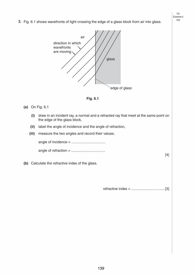
7
0625/3/M/J/03 [Turn over
6 Fig. 6.1 shows wavefronts of light crossing the edge of a glass block from air into glass.
Fig. 6.1
(a) On Fig. 6.1
(i) draw in an incident ray, a normal and a refracted ray that meet at the same point onthe edge of the glass block,
(ii) label the angle of incidence and the angle of refraction,
(iii) measure the two angles and record their values.
angle of incidence = ..................................
angle of refraction = ..................................[4]
(b) Calculate the refractive index of the glass.
refractive index = ..................................[3]
edge of glass
glass
air
direction in whichwavefrontsare moving
ForExaminer’s
Use3.
139

8
0625/3/M/J/03
7 In a thunderstorm, both light and sound waves are generated at the same time.
(a) How fast does the light travel towards an observer?
speed = .................................. [1]
(b) Explain why the sound waves always reach the observer after the light waves.
......................................................................................................................................[1]
(c) The speed of sound waves in air may be determined by experiment using a source thatgenerates light waves and sound waves at the same time.
(i) Draw a labelled diagram of the arrangement of suitable apparatus for theexperiment.
(ii) State the readings you would take.
...................................................................................................................................
...................................................................................................................................
...................................................................................................................................
(iii) Explain how you would calculate the speed of sound in air from your readings.
...................................................................................................................................
...................................................................................................................................[4]
ForExaminer’s
Use4.
140

8
0625/03 M/J/04
6 Fig. 6.1 shows a ray PQ of blue light incident on the side of a rectangular glass block.
Fig. 6.1
(a) (i) By drawing on Fig. 6.1, continue the ray PQ through and beyond the block.
(ii) Mark the angle of incidence at CD with the letter i and the angle of refraction at CDwith the letter r.
[3]
(b) The speed of light in air is 3.0 x 10⁸ m/s and the speed of light in glass is 2.0 x 10⁸ m/s.
(i) Write down a formula that gives the refractive index of glass in terms of thespeeds of light in air and glass.
refractive index =
(ii) Use this formula to calculate the refractive index of glass.
refractive index = …………………[2]
(c) The frequency of the blue light in ray PQ is 6.0 x 10¹⁴ Hz.Calculate the wavelength of this light in air.
wavelength = ……………..……[2]
A B
DCQ
P
glass
air
Fig. 6.1
ForExaminer’s
Use
© UCLES 2004
5.
141

9
0625/03 M/J/04 [Turn over
7 Fig. 7.1 shows the cone of a loudspeaker that is producing sound waves in air.At any given moment, a series of compressions and rarefactions exist along the line XY.
Fig. 7.1
(a) On Fig. 7.1, use the letter C to mark three compressions and the letter R to mark threerarefactions along XY. [1]
(b) Explain what is meant by
(i) a compression,
...................................................................................................................................
...................................................................................................................................
(ii) a rarefaction.
...................................................................................................................................
...................................................................................................................................[2]
(c) A sound wave is a longitudinal wave. With reference to the sound wave travelling alongXY in Fig. 7.1, explain what is meant by a longitudinal wave.
..........................................................................................................................................
......................................................................................................................................[2]
(d) There is a large vertical wall 50 m in front of the loudspeaker. The wall reflects thesound waves.The speed of sound in air is 340 m/s.Calculate the time taken for the sound waves to travel from X to the wall and to return to X.
time = …………………[2]
air
cone
wires
X Y
ForExaminer’s
Use
© UCLES 2004
6.
142
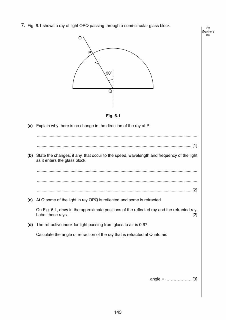
9
0625/03/M/J/05 [Turn over
6 Fig. 6.1 shows a ray of light OPQ passing through a semi-circular glass block.
Fig. 6.1
(a) Explain why there is no change in the direction of the ray at P.
..........................................................................................................................................
..................................................................................................................................... [1]
(b) State the changes, if any, that occur to the speed, wavelength and frequency of the lightas it enters the glass block.
..........................................................................................................................................
..........................................................................................................................................
..................................................................................................................................... [2]
(c) At Q some of the light in ray OPQ is reflected and some is refracted.
On Fig. 6.1, draw in the approximate positions of the reflected ray and the refracted ray.Label these rays. [2]
(d) The refractive index for light passing from glass to air is 0.67.
Calculate the angle of refraction of the ray that is refracted at Q into air.
angle = ………………. [3]
30°
Q
P
O
ForExaminer’s
Use
© UCLES 2005
7.
143
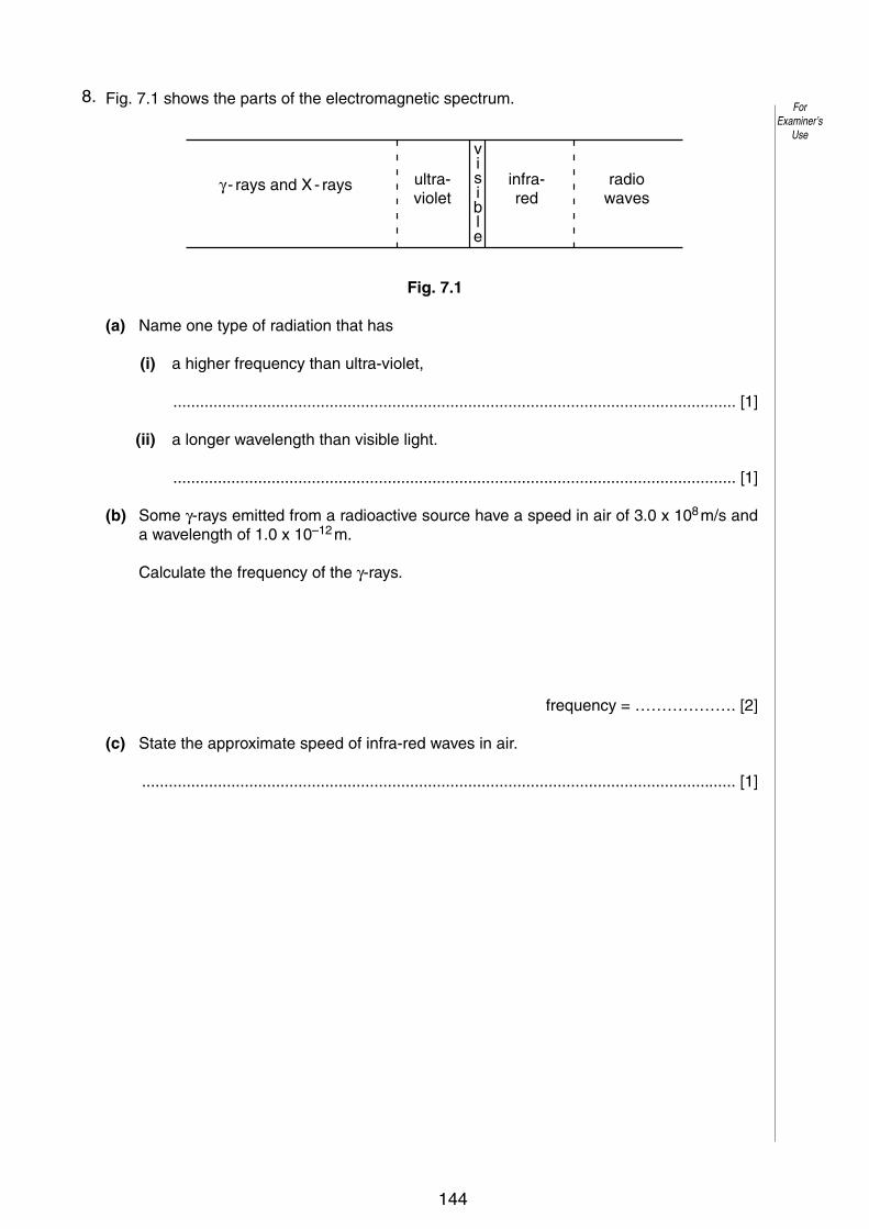
10
0625/03/M/J/05
7 Fig. 7.1 shows the parts of the electromagnetic spectrum.
Fig. 7.1
(a) Name one type of radiation that has
(i) a higher frequency than ultra-violet,
.............................................................................................................................. [1]
(ii) a longer wavelength than visible light.
.............................................................................................................................. [1]
(b) Some !-rays emitted from a radioactive source have a speed in air of 3.0 x 10⁸ m/s anda wavelength of 1.0 x 10⁻¹² m.
Calculate the frequency of the !-rays.
frequency = ………………. [2]
(c) State the approximate speed of infra-red waves in air.
..................................................................................................................................... [1]
! - rays and X - rays ultra-violet
infra-red
radiowaves
visible
ForExaminer’s
Use
© UCLES 2005
8.
144

7
0625/03/M/J/06 [Turn over
ForExaminer’s
Use
© UCLES 2006
6 Fig. 6.1 shows white light incident at P on a glass prism. Only the refracted red ray PQ is shown in the prism.
PQ
white light
red ray
screen
Fig. 6.1
(a) On Fig. 6.1, draw rays to complete the path of the red ray and the whole path of the violet ray up to the point where they hit the screen. Label the violet ray. [3]
(b) The angle of incidence of the white light is increased to 40°. The refractive index of the glass for the red light is 1.52.
Calculate the angle of refraction at P for the red light.
angle of refraction = ........................[3]
(c) State the approximate speed of
(i) the white light incident at P, speed = ........................ [1]
(ii) the red light after it leaves the prism at Q. speed = ........................ [1]
9.
145

8
0625/03/M/J/06
ForExaminer’s
Use
© UCLES 2006
7 Fig. 7.1 shows how the air pressure at one instant varies with distance along the path of a continuous sound wave.
air pressure
normalair pressure
P X Y
distance in directionof travel of the wave
Fig. 7.1
(a) What type of waves are sound waves?
......................................................................................................................................[1]
(b) On Fig. 7.1, mark on the axis PY
(i) one point C where there is a compression in the wave, [1]
(ii) one point R where there is a rarefaction in the wave. [1]
(c) Describe the motion of a group of air particles situated on the path of the wave shown in Fig. 7.1.
..........................................................................................................................................
..........................................................................................................................................
......................................................................................................................................[2]
(d) The sound wave shown has speed of 340 m / s and a frequency of 200 Hz. Calculate the distance represented by PX on Fig. 7.1.
distance = ........................[2]
10.
146

Topic 4:Electricity & Magnetism
Charge• Charge is a property that objects can have.
• Charge can be positive (+) or negative (-).
• Charge is measured in coulombs (C).
• Conductors allow charge to move (metals & graphite).
• Insulators prevent charge from moving (Most non-metals).
• Electrons are usually responsible for movement of charge (current).
Charging by Friction• When two insulators are rubbed together,
ELECTRONS are transferred from one to the other and the objects become charged.
• This is called charging by friction because friction is the force that moves the electrons.
• Only electrons move. Positive charge does not move.
1
2
3
147
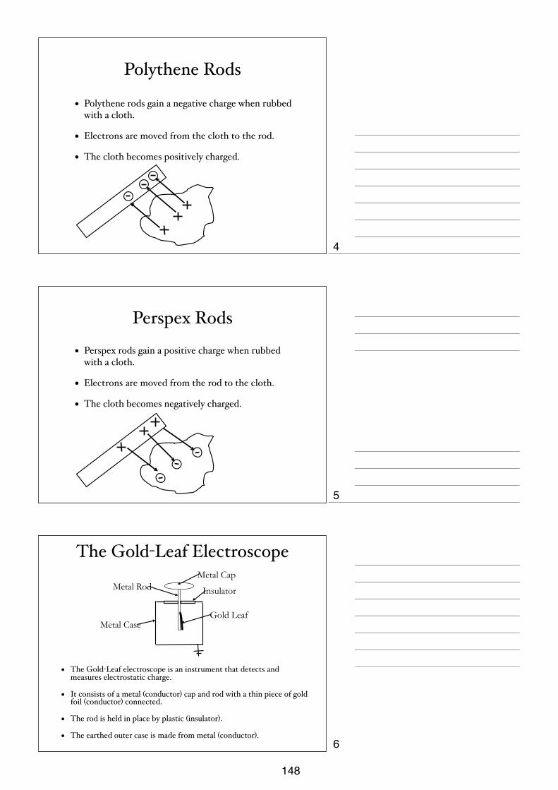
Polythene Rods
• Polythene rods gain a negative charge when rubbed with a cloth.
• Electrons are moved from the cloth to the rod.
• The cloth becomes positively charged.
Perspex Rods
• Perspex rods gain a positive charge when rubbed with a cloth.
• Electrons are moved from the rod to the cloth.
• The cloth becomes negatively charged.
The Gold-Leaf Electroscope
• The Gold-Leaf electroscope is an instrument that detects and measures electrostatic charge.
• It consists of a metal (conductor) cap and rod with a thin piece of gold foil (conductor) connected.
• The rod is held in place by plastic (insulator).
• The earthed outer case is made from metal (conductor).
Metal Cap
Gold Leaf
Metal Rod
Metal Case
Insulator
4
5
6
148

The Law of Electrostatics• If charged objects are placed beside each other, they
experience a force.
• The force depends upon the charges on the objects.
• An electric field surrounds the charges. This is a region of influence on other charges.
attract
repel
attract
repel
The Law of Electrostatics• This can be summarised as:
Opposite Charges Attract.Like Charges Repel.
Summary of Quantities
Quantity Symbol Unit Unit’s Symbol
Current I Ampere A
Potential Difference (Voltage)
V Volt V
Resistance R Ohm Ω
7
8
9
149

Current/Voltage Graphs
• The characteristics of a component can be shown by graphing the current through it for varying voltages.
• This graph is called the characteristic of the component.
• Negative p.d.s are plotted as well as positive ones.
Ohmic Resistors
• Ohmic resistors have a proportional relationship between current and pd. This is because the resistance remains constant for all voltages.
current
p.d.
Filament Lamp• A filament lamp or standard resistor does not ‘behave
itself ’ as well as an ohmic resistor. The resistance increases with voltage as the wire gets hotter.
p.d.
current
10
11
12
150
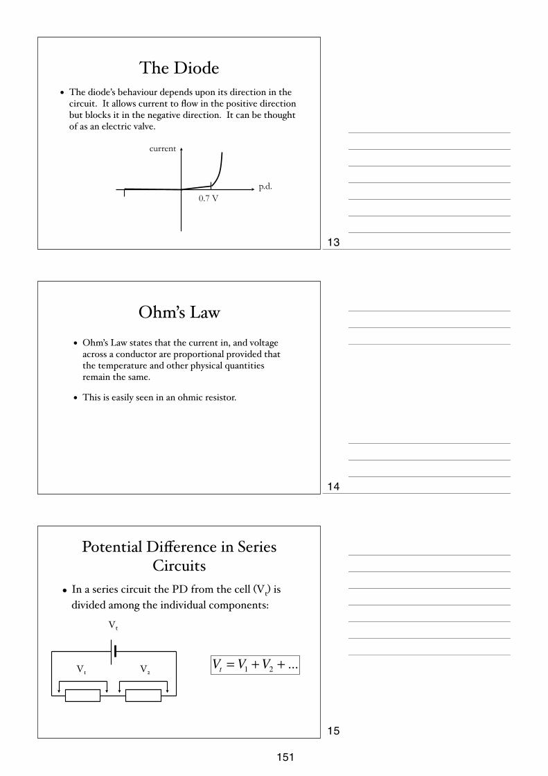
The Diode• The diode’s behaviour depends upon its direction in the
circuit. It allows current to flow in the positive direction but blocks it in the negative direction. It can be thought of as an electric valve.
p.d.
current
0.7 V
Ohm’s Law• Ohm’s Law states that the current in, and voltage
across a conductor are proportional provided that the temperature and other physical quantities remain the same.
• This is easily seen in an ohmic resistor.
Potential Difference in Series Circuits
• In a series circuit the PD from the cell (Vt) is divided among the individual components:
Vt
V1 V2Vt = V1 +V2 + ...
13
14
15
151

Current in Series Circuits
• In a series circuit the Current is the same at all points in the circuit. This is because of the conservation of charge.
It It
I1 I2 I3
It = I1 = I2 = ...
Resistance in Series Circuits
• The Combined Resistance (Rt) is equal to the sum of the individual resistances:
Rt
R1 R2
Rt = R1 + R2 + ...
Potential Difference in Parallel
• In a Parallel circuit the PD across each strand is the same as the PD supplied to the strand since the voltage is between the same two points in each case.
Vt
V1
V2
Vt = V1 = V2 = ...
16
17
18
152
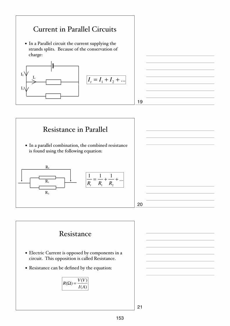
Current in Parallel Circuits
• In a Parallel circuit the current supplying the strands splits. Because of the conservation of charge:
It I1
I2
It = I1 + I2 + ...
Resistance in Parallel
• In a parallel combination, the combined resistance is found using the following equation:
R2
R1
Rt
1Rt
=1R1
+1R2
+ ...
Resistance
• Electric Current is opposed by components in a circuit. This opposition is called Resistance.
• Resistance can be defined by the equation:
R(Ω) = V (V )I(A)
19
20
21
153

Current• Current is the rate at which charge (coulombs) passes a point in
a circuit.
• Current is measured with an ammeter in a circuit which is placed in series at the point where the current needs to be measured.
I(A) = Q(C)t(s)
Potential Difference• Electrical Energy is given to the charges in a cell (battery). This energy is
given up in the components.
• Both cells and components in a circuit have a voltage across them.
• Potential Difference is measured in a circuit with an voltmeter. It should be placed in parallel across the two points where the PD is to be found.
V (V ) = ΔEnergy(J )Q(C)
The Potential Divider
• The total PD across the resistors is shared by the resistors.
• The share of the voltage that each resistor gets depends upon its resistance.
• If R1 is large compared to R2 then it will have a much bigger share of the voltage across it.
Vt
V1=IR1 V2=IR2
I
22
23
24
154

Simpler Design
• The Potential Divider can be made adjustable by using a variable resistor and taking a voltage from the rheostat.
Vt
I
V1
Task• Using the 12V setting on the power pack, a
variable resistor, a voltmeter a bulb and leads, construct a circuit that supplies the bulb with exactly 4.56 V.
V
Energy in D.C. CircuitsIt has been shown that
Voltage is the Work Done per Coulomb
But we also know that:
So:
V =WDQ
I =Qt
Q = ItEnergy = VQ
Energy = VIt
25
26
27
155
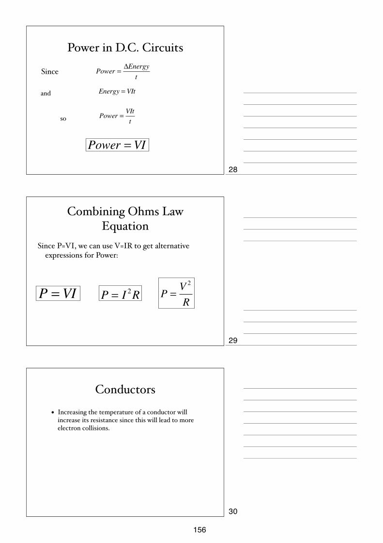
Power in D.C. Circuits
Since
and
so
Power =ΔEnergy
t
Energy = VIt
Power =VItt
Power = VI
Combining Ohms Law Equation
Since P=VI, we can use V=IR to get alternative expressions for Power:
P = VI P = I 2R P =V 2
R
Conductors
• Increasing the temperature of a conductor will increase its resistance since this will lead to more electron collisions.
28
29
30
156
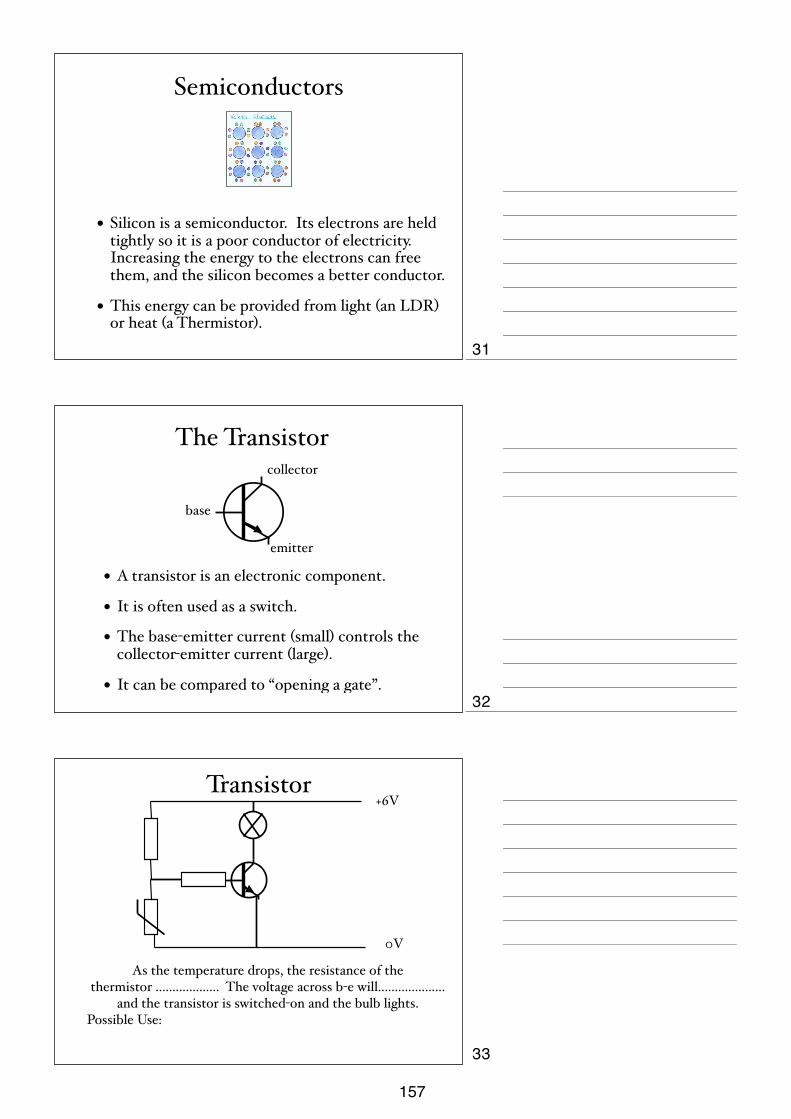
Semiconductors
• Silicon is a semiconductor. Its electrons are held tightly so it is a poor conductor of electricity. Increasing the energy to the electrons can free them, and the silicon becomes a better conductor.
• This energy can be provided from light (an LDR) or heat (a Thermistor).
The Transistor
• A transistor is an electronic component.
• It is often used as a switch.
• The base-emitter current (small) controls the collector-emitter current (large).
• It can be compared to “opening a gate”.
base
emitter
collector
Transistor+6V
0V
As the temperature drops, the resistance of the thermistor ................... The voltage across b-e will....................
and the transistor is switched-on and the bulb lights.Possible Use:
31
32
33
157

Transistor+6V
0V
As the temperature rises, the resistance of the thermistor ................... The voltage across b-e will....................
and the transistor is switched-on and the bulb lights.Possible Use:
Transistor+6V
0V
As the light level drops, the resistance of the LDR ................... The voltage across b-e will.................... and the transistor is
switched-on and the bulb lights.Possible Use:
Transistor+6V
0V
As the light level rises, the resistance of the LDR ................... The voltage across b-e will.................... and the transistor is
switched-on and the bulb lights.Possible Use:
34
35
36
158
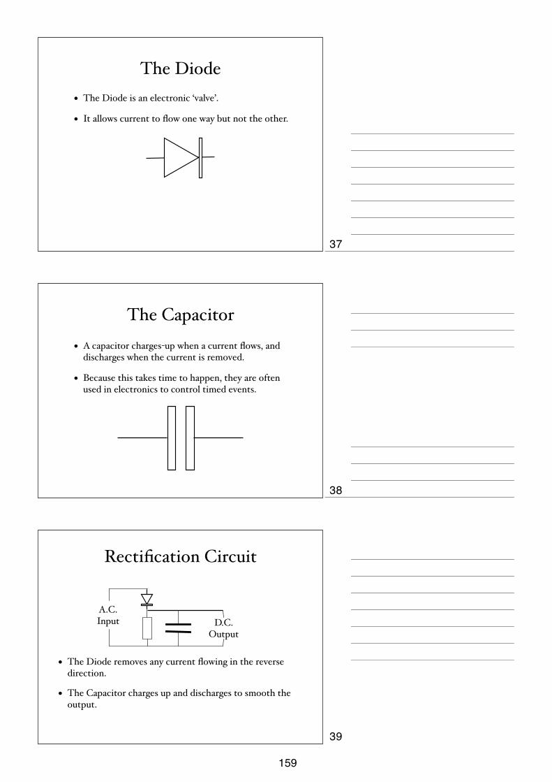
The Diode• The Diode is an electronic ‘valve’.
• It allows current to flow one way but not the other.
The Capacitor• A capacitor charges-up when a current flows, and
discharges when the current is removed.
• Because this takes time to happen, they are often used in electronics to control timed events.
Rectification Circuit
• The Diode removes any current flowing in the reverse direction.
• The Capacitor charges up and discharges to smooth the output.
A.C. Input D.C.
Output
37
38
39
159
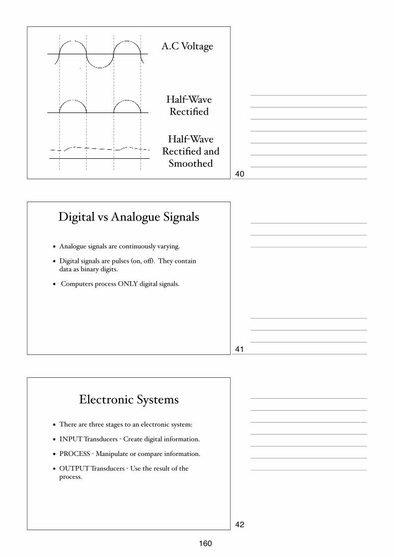
A.C Voltage
Half-Wave Rectified
Half-Wave Rectified and
Smoothed
Digital vs Analogue Signals
• Analogue signals are continuously varying.
• Digital signals are pulses (on, off). They contain data as binary digits.
• Computers process ONLY digital signals.
Electronic Systems
• There are three stages to an electronic system:
• INPUT Transducers - Create digital information.
• PROCESS - Manipulate or compare information.
• OUTPUT Transducers - Use the result of the process.
40
41
42
160
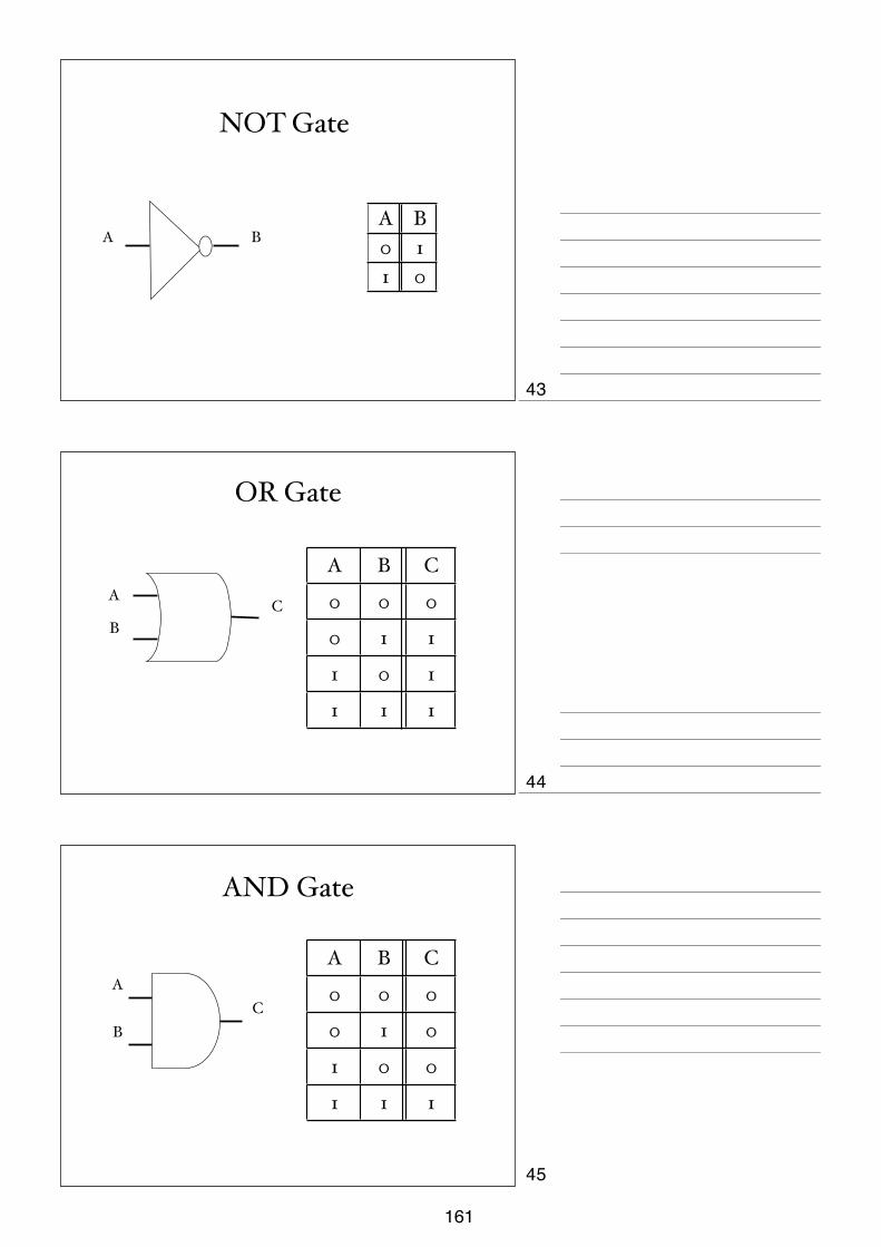
NOT Gate
A BA B0 11 0
OR Gate
B
AC
A B C
0 0 0
0 1 1
1 0 1
1 1 1
AND Gate
AC
B
A B C
0 0 0
0 1 0
1 0 0
1 1 1
43
44
45
161

Tasks• Build an alarm clock for a deaf person that will light up at dawn.
• Build a eco-friendly device that would tell you if your pool was too cold for swimming. The device should light up when you press a button.
• Build a device that will sound an alarm at Isha. It must activate a buzzer when it is dark and the device is switched on.
• Build a fire alarm that activates a buzzer and a warning light when it gets too hot. The alarm should have a test button for the battery.
Production of a Cathode Ray
• The heating element ‘boils’ the excess electrons off the cathode.
• Most of the electrons hit the Anode, but some pass through the gap in a high speed Cathode Ray.
H
Heating Element
Cathode
Anode
Vacuum
The Electron Gun
• A television produces a picture by focusing a cathode ray onto a screen that glows when the beam hits it.
• Computer monitors and Cathode Ray Oscilloscopes (CROs) also use this idea.
• X-Ray generators also use cathode rays.
46
47
48
162

Uses of Cathode Rays
Magnets• There are two types of magnetic pole, North and
South.
• Fields run from North to South and can be shown with iron filings.
• Magnets attract magnetic materials.
• Ferrous materials (containing iron) are often magnetic, especially steel.
• Magnetic materials can have magnetism induced. This is called ‘magnetising’.
• Pure iron loses its magnetism easily.
Magnetising and Demagnetising
• Methods of magnetising include:
• Stroking
• Field induction (DC Coil)
• Methods of demagnetising include
• Heating
• Hammering
• AC coil
49
50
51
163
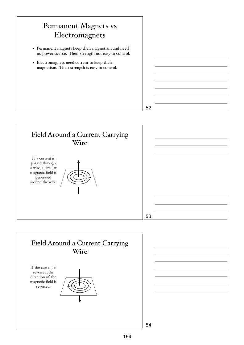
Permanent Magnets vs Electromagnets
• Permanent magnets keep their magnetism and need no power source. Their strength not easy to control.
• Electromagnets need current to keep their magnetism. Their strength is easy to control.
Field Around a Current Carrying Wire
If a current is passed through a wire, a circular magnetic field is
generated around the wire.
Field Around a Current Carrying Wire
If the current is reversed, the
direction of the magnetic field is
reversed.
52
53
54
164
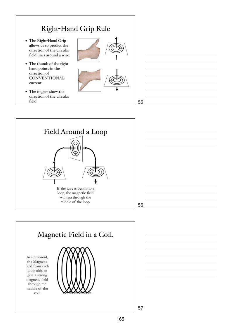
Right-Hand Grip Rule• The Right-Hand Grip
allows us to predict the direction of the circular field lines around a wire.
• The thumb of the right hand points in the direction of CONVENTIONAL current.
• The fingers show the direction of the circular field.
Field Around a Loop
If the wire is bent into a loop, the magnetic field
will run through the middle of the loop.
Magnetic Field in a Coil.
In a Solenoid, the Magnetic
field from each loop adds to give a strong
magnetic field through the
middle of the coil.
55
56
57
165

Field Around a CoilThe magnetic field around a solenoid is similar to that of
a bar magnet.
The Relay
• A relay is a device that uses electromagnetism to allow a small current to switch-on a large current.
• When the small current flows, the solenoid becomes magnetised and a switch is activated.
small current large
current
starter motor
spring
iron
The Reed Relay
• Another variation on the relay involves two strips of metal (reeds) placed side by side. One is iron, and one is non-magnetic.
• When the current flows, the magnetic reed makes contact with the non-metal.
large current
non-magnetic reed
magnetic reed
small current
58
59
60
166

The Motor Effect• If a current is placed in a magnetic field, the wire is forced
out.
NS
The Motor Effect• If a current is placed in a magnetic field, the wire is forced
out.
N S
Left Hand Rule
• To predict the direction of the movement we use Fleming’s Left-hand rule.
First finger - Field
seCond finger - Current
thuMb - Movement
61
62
63
167

The DC Motor• If we pass a current through a loop of wire, and
place it in a magnetic field, we get forces due to the motor effect.
commutator
NS
Design Improvements
• Increasing the supply voltage (current) increases the strength of the motor.
• Increasing the strength of the magnetic field increases the strength of the motor.
• Adding more loops increases the strength of the motor.
Induction• Electromagnetic Induction can be seen as the opposite to
the Motor Effect.
Motor EffectElectrical Energy
Kinetic Energy
InductionKinetic Energy
Electrical Energy
G
A current is induced when the magnet is moved through the
coil, but no current is induced when the
magnet is stationary.
64
65
66
168
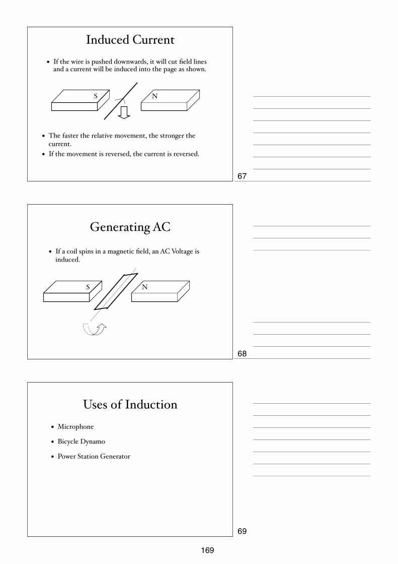
Induced Current• If the wire is pushed downwards, it will cut field lines
and a current will be induced into the page as shown.
• The faster the relative movement, the stronger the current.
• If the movement is reversed, the current is reversed.
NS
Generating AC
• If a coil spins in a magnetic field, an AC Voltage is induced.
NS
Uses of Induction• Microphone
• Bicycle Dynamo
• Power Station Generator
67
68
69
169
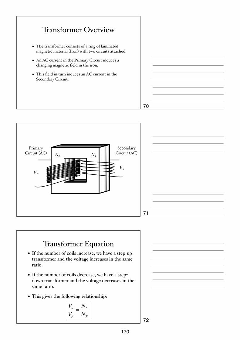
Transformer Overview
• The transformer consists of a ring of laminated magnetic material (Iron) with two circuits attached.
• An AC current in the Primary Circuit induces a changing magnetic field in the iron.
• This field in turn induces an AC current in the Secondary Circuit.
VPVS
NSNP
Primary Circuit (AC)
Secondary Circuit (AC)
Transformer Equation• If the number of coils increase, we have a step-up
transformer and the voltage increases in the same ratio.
• If the number of coils decrease, we have a step-down transformer and the voltage decreases in the same ratio.
• This gives the following relationship:
VSVP
=NS
NP
70
71
72
170
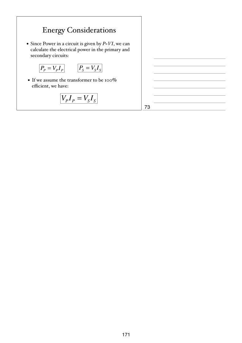
Energy Considerations
• Since Power in a circuit is given by P=VI, we can calculate the electrical power in the primary and secondary circuits:
• If we assume the transformer to be 100% efficient, we have:
PS = VSISPP = VPIP
VPIP = VSIS73
171

1
Electricity and Magnetism Quantity and
symbol Word equation / definition Symbol equation units
Charge, q, Q Charge = current x time The charge on one electron is 1.6 x 10⁻¹⁹ Q = I t Coulombs,
C, As
Electric Field
An electric field is a region in which an electric charge experiences a force. The direction of the field is the direction in which a positive test charge would move.
Electro-motive force, E, E.M.F.,
e.m.f.
The electro-motive force, or E.M.F., is defined as the amount of energy supplied by a source in driving charge around a complete circuit.
V
Potential Difference, p.d.,V
The potential difference is the energy difference per coulomb of charge that the current is carrying before and after a component.
1 V = 1 J/C V mV
Current, I
Current is the rate of flow of charge. Conventional current is from positive to negative. This is the opposite direction to the flow of electrons.
I = Q t
A mA
Resistance, R
Resistance is a property of a material that opposes the flow of current.
Resistance = potential difference current
R = V I
Ohms Ω
Resistance, R Resistance is directly proportional to the length of a piece of wire, for constant temperature and cross-section area.
R α L Ohms Ω
Resistance, R
Resistance is indirectly proportional to the cross-section area of a piece of wire, for constant temperature and length. Material and temperature also affect the resistance.
R α 1 A
Ohms Ω
Series Circuits
The current in a series circuit is the same at every point. The sum of the p.d.’s across the components in a series circuit is equal to the total p.d. across the supply.
Parallel Circuits
The current from the source is the sum of the currents in the separate branches of a parallel circuit. The p.d.’s across each parallel branch in a parallel circuit is the same.
Resistors, in series Total resistance = the sum of the resistors in series RT = R1 + R2
Ohms Ω
Resistors, in parallel The combined resistance of 2 resistors in parallel is less than that of either resistor by itself.
1 1 1 RT = R1 + R2
Ohms Ω
Electrical Energy, E Electrical energy = potential difference x current x time E = V I t Joules, J
Electrical Power, P Electrical power = potential difference x P = I V Watts, W
172

2
current Or Electrical power = potential difference2
resistance Or Electrical power = current2 x resistance
P = V2
R P = I2R
Electromagnetic Induction
A changing magnetic field can induce a e.m.f. in a closed circuit. The direction of the induced e.m.f. opposes the change causing it.
Transformer, (for 100% efficiency)
Ratio of the potential difference in the primary coil to the secondary coil is equal to the ratio of the number of turns on the primary to the secondary, and equal to the ratio of the current in the secondary to the current in the primary
np/ns = Vp/Vs =Is/Ip
No units, it’s a ratio
The Motor Effect A current carrying wire in a magnetic field experiences a force. The direction of that force can be worked out using Fleming’s Left Hand Rule.
Thermionic Emission
A heated piece of metal will release electrons.
173
iGCSE PhysicsPast Paper QuestionsPaper 1 Compilation
Electricity & Magnetism
174

12
0625/1/M/J/02
25 A girl stands in front of a rock face.
The girl claps her hands once. The speed of sound in air is 330 m / s.
How long is it before she hears the echo?
A s B s C s D s
26 Which diagram best shows the pattern of field lines around a bar magnet?
N S
A B
N S
N S
C D
N S
330______2 x 660
330___660
660___330
2 x 660______330
660 m
rock face
15
0625/1/M/J/02 [Turn over
34 When electricity is transmitted over long distances, energy is wasted. How can the wastedenergy be kept as small as possible?
A Keep the current in the transmission lines as large as possible.
B Keep the power supplied to the transmission lines as large as possible.
C Keep the resistance of the transmission lines as large as possible.
D Keep the voltage supplied to the transmission lines as large as possible.
35 The diagram shows a transformer.
What is the voltmeter reading?
A 1.2 V B 12 V C 120 V D 1200 V
12 Va.c. V
300 turns30 turns
a.c. voltmeter
1.
2.
3.
175

13
0625/1/M/J/02 [Turn over
27 Which materials are suitable to make a permanent magnet and the core of an electromagnet?
28 Which two electrical quantities are measured in volts?
A current and e.m.f.
B current and resistance
C e.m.f. and potential difference
D potential difference and resistance
29 Which of the following pieces of copper wire has the greatest electrical resistance?
30 A 20 ! resistor and a 10 ! resistor are connected in parallel.
What is their combined resistance?
A less than 10 !
B 10 !
C 20 !
D more than 20 !
20 !
10 !
length / m diameter / mm
A 5.0 0.05
B 5.0 0.10
C 50 0.05
D 50 0.10
permanent magnet core of an electromagnet
A iron iron
B iron steel
C steel iron
D steel steel
4.
5.
6.
7.
176

14
0625/1/M/J/02
31 The diagram shows an incomplete circuit.
Which component should be connected in the space to make the lamp light?
32 Why are the electric lamps in a house lighting circuit normally connected in parallel?
A The current in every circuit must be the same.
B The lamps are always switched on and off at the same time.
C The voltage across each lamp must be the mains voltage.
D When one of the lamps blows, all the others go out.
33 In the circuit shown, one of the fuses blows and all the lamps go out.
Which fuse blows?
A
B CD
+ –
A B C D
A
space
8.
9.
10.
177

16
0625/1/M/J/02
36 The diagram shows part of a circuit used to switch street lamps on and off automatically.
What is the effect on the light-dependent resistor (LDR) when it gets dark?
37 An alternating potential difference (p.d.) is applied to the Y-plates of a cathode-ray oscilloscope.The time-base is turned off.
Which of the following patterns would appear on the screen?
38 What is a beta-particle?
A a helium nucleus
B a high-energy electron
C four protons
D two neutrons
A B C D
+
–
LDR
resistance of LDR p.d. across LDR
A decreases decreases
B decreases increases
C increases decreases
D increases increases
11.
12.
178

12
0625/01/M/J/03
26 A student wishes to use a magnetising coil to make a permanent magnet from a piece of metal.
Which metal should she use?
A aluminium
B copper
C iron
D steel
27 A metal rod XY is placed near a magnet. End X is attracted when it is placed near to the north poleof the magnet, and also when it is placed near to the south pole.
How does end Y behave when it is placed, in turn, near to the two poles of the magnet?
X Y
N
S
attractionX Y
N
S
attraction
metal
Y near north pole Y near south pole
A attraction attraction
B attraction repulsion
C repulsion attraction
D repulsion repulsion
13.
14.
179

13
0625/01/M/J/03 [Turn over
28 When the potential difference (p.d.) across a piece of resistance wire is changed, the currentthrough the wire also changes.
The temperature of the wire is kept the same.
Which graph shows how the p.d. and current are related?
29 Two faulty ammeters and two perfect ammeters are connected in series in the circuit shown.
The readings on the ammeters are
A1 2.9 A
A2 3.1 A
A3 3.1 A
A4 3.3 A
Which two ammeters are faulty?
A A1 and A2 B A1 and A4 C A2 and A3 D A3 and A4
30 Which electrical component would not normally be found in a battery-operated torch (flashlight)?
A B C D
A1 A2 A3 A4
00 p.d.
A
00 p.d.
B
00 p.d.
C
00 p.d.
D
current current current current
15.
16.
17.
180

14
0625/01/M/J/03
31 A student connects two lamps in the circuit shown.
Which switches must he close to light both lamps?
A 1 and 2
B 1, 2 and 3
C 1 and 3
D 2 and 3
32 A student makes four circuits.
In which circuit are both lamps protected by the fuse?
A B
C D
2
1
3
18.
19.
181

15
0625/01/M/J/03 [Turn over
33 Four lamps are labelled ‘60 W 240 V’.
In which circuit are the lamps connected so that they all work at normal brightness?
34 The diagram shows a solenoid connected to a sensitive voltmeter.
Which of the following would give a zero reading on the voltmeter?
A holding the magnet stationary inside the solenoid
B moving the magnet away from the solenoid
C moving the magnet towards the solenoid
D moving the solenoid towards the magnet
V
solenoid
magnetS
N
A
240 V
B
240 V
C
240 V
D
240 V
20.
21.
182

16
0625/01/M/J/03
35 The diagram shows a transformer with an alternating voltage of 100 V applied to the primary coil.
What is the voltage produced across the secondary coil?
A 50 V B 100 V C 200 V D 8000 V
36 The diagram below shows the screen of a cathode-ray oscilloscope tube.
The tube is placed between a pair of charged plates.
Which diagram shows the new position of the spot?
+
+
+
+
+
–
–
–
–
–
A
+
+
+
+
+
–
–
–
–
–
B
+
+
+
+
+
–
–
–
–
–
C
+
+
+
+
+
–
–
–
–
–
D
spot of light
primary coil secondary coil
100 V (40 turns) (80 turns)
21.
22.
183

17
0625/01/M/J/03 [Turn over
37 An electrical component X is placed in water, as shown.
When the temperature of the water is increased, the reading on the ammeter increases.
What is component X?
A a capacitor
B a light-dependent resistor
C a reed relay
D a thermistor
38 Which type of radiation can be stopped by a sheet of paper?
A !-particles
B "-particles
C #-rays
D X-rays
39 The half-life of a radioactive substance is 5 hours. A sample is tested and found to contain 0.48 gof the substance.
How much of the substance was present in the sample 20 hours before the sample was tested?
A 0.03 g
B 0.12 g
C 1.92 g
D 7.68 g
X
A
thermometer
water
13
UCLES 2004 0625/01/M/J/04 [Turn over
26 An engineer standing at P hears the sound of an explosion at X.
Z
YX
WV
P
DANGER - BLASTING
After the explosion, she hears two bangs. One bang is heard a fraction of a second after the
other.
The second bang is an echo from
A XY.
B PV.
C ZY.
D WX.
27 How can a permanent magnet be demagnetised?
A cool the magnet for a long time
B hit the magnet repeatedly with a hammer
C leave the magnet in a coil which carries direct current
D pass a small current through the magnet
28 An electromagnet is used to separate magnetic metals from non-magnetic metals.
Why is steel unsuitable as the core of the electromagnet?
A It is a good conductor of electricity.
B It forms a permanent magnet.
C It has a high density.
D It has a high thermal capacity.
23.
24.
25.
184

14
! UCLES 2004 0625/01/M/J/04
29 Which circuit shows how a voltmeter is connected to measure the potential difference across the
cell?
A B C D
VV
V
V
30 A polythene rod repels an inflated balloon hanging from a nylon thread.
What charges must the rod and the balloon carry?
A The rod and the balloon carry opposite charges.
B The rod and the balloon carry like charges.
C The rod is charged but the balloon is not.
D The balloon is charged but the rod is not.
31 An electrical component is to be placed in the circuit at Z, to allow the brightness of the lamp to
be varied from bright to dim.
Z
What should be connected at Z?
A B C D
V
11
© UCLES 2005 0625/01/M/J/05 [Turn over
24 A fire alarm is not loud enough. An engineer adjusts it so that it produces a note of the same pitch
which is louder.
What effect does this have on the amplitude and on the frequency of the sound?
amplitude frequency
A larger larger
B larger same
C same larger
D same same
25 To estimate the width of a valley, a climber starts a stopwatch as he shouts. He hears an echo
from the opposite side of the valley after 1.0 s.
valley
sound
climber
The sound travels at 340 m / s.
What is the width of the valley?
A 85 m B 170 m C 340 m D 680 m
26 Which material is used for the core of an electromagnet?
A aluminium
B copper
C iron
D steel
26.
27.
28.
29.
185

15
U CLE S 2004 0625/01/M/J/04 [Turn over
32 The circuit shown conta ins four lamps and three switches.
lamp 1
lamp 2
lamp 3
lamp 4
switch 1
switch 3
switch 2
Which switches must be closed to light only lamps 1 and 3?
A switch 1 only
B switch 1 and switch 2 only
C switch 1 and switch 3 only
D switch 2 and switch 3 only
33 The diagram shows a torch conta ining two 2 V ce lls, a switch and a lamp.
plasticcase
brassconnecting
stripswitch
lamp
Wha t is the circuit diagram for the torch?
CBA D
30.
31.
186

16
! UCLES 2004 0625/01/M/J/04
34 Which statement is correct?
A A fuse is included in a circuit to prevent the current becoming too high.
B A fuse should be connected to the neutral wire in a plug.
C An electric circuit will only work if it includes a fuse.
D An earth wire is needed to prevent the fuse blowing.
35 A straight wire carrying a current produces a magnetic field.
Which diagram shows the correct shape of the field?
current current
current current
A B
C D
32.
33.
187

17
U CLE S 2004 0625/01/M/J/04 [Turn over
36 A student carries out an experiment to see the e ffect of a magne tic fie ld on a wire carrying a current.
The wire moves upwards as shown.
directionof current
N S
wire movesupwards
Wha t should the student do to make the wire move downwards?
A change the direction of the current
B move the poles of the magne t closer toge ther
C send a sma ller current through the wire
D use a stronger magne t
37 A beam of ca thode rays passes through an e lectric fie ld be tween two para lle l pla tes.
+ + + + + +
_ _ _ _ _ _
cathode rays
In which direction is the beam de flected?
A into the page
B out of the page
C towards the bottom of the page
D towards the top of the page
34.
35.
188
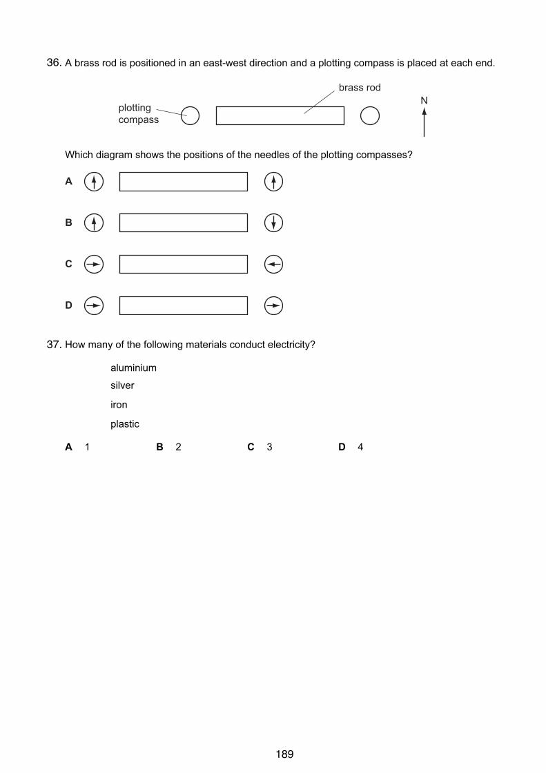
12
© UCLES 2005 0625/01/M/J/05
27 A brass rod is positioned in an east-west direction and a plotting compass is placed at each end.
Nplottingcompass
brass rod
Which diagram shows the positions of the needles of the plotting compasses?
A
B
C
D
28 How many of the following materials conduct electricity?
aluminium
silver
iron
plastic
A 1 B 2 C 3 D 4
36.
37.
189

13
© UCLES 2005 0625/01/M/J/05 [Turn over
29 In which circuit does the voltmeter read the potential difference across the lamp?
C
V
D
V
A B
V
V
30 In the circuit below, X and Y are identical 6 V lamps.
switchX
Y
6 V
What happens when the switch is closed?
A X lights more brightly than Y.
B Y lights more brightly than X.
C X and Y light with equal brightness.
D Neither X nor Y light.
38.
39.
190
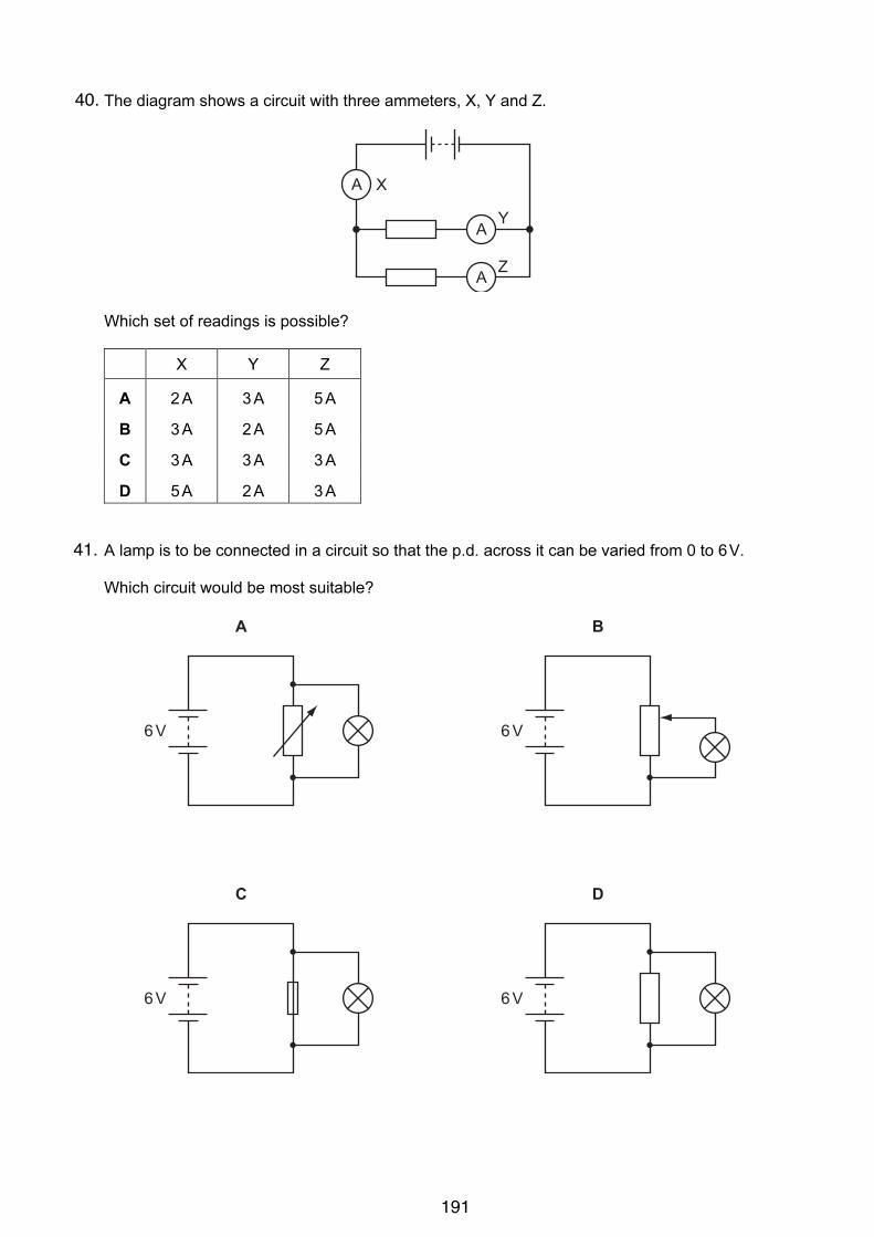
14
© UCLES 2005 0625/01/M/J/05
31 The diagram shows a circuit with three ammeters, X, Y and Z.
A
A
A
X
Y
Z
Which set of readings is possible?
X Y Z
A 2 A 3 A 5 A
B 3 A 2 A 5 A
C 3 A 3 A 3 A
D 5 A 2 A 3 A
32 A lamp is to be connected in a circuit so that the p.d. across it can be varied from 0 to 6 V.
Which circuit would be most suitable?
6 V
A
6 V
B
6 V
C
6 V
D
40.
41.
191
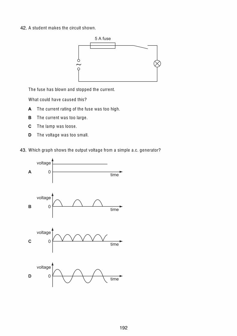
15
© UCLES 2005 0625/01/M/J/05 [Turn over
33 A student makes the circuit shown.
5 A fuse
The fuse has blown and stopped the current.
Wha t could have caused this?
A The current ra ting of the fuse was too high.
B The current was too large .
C The lamp was loose .
D The voltage was too sma ll. 34 Which graph shows the output voltage from a simple a .c. genera tor?
0Atime
voltage
0Btime
voltage
0Ctime
voltage
0Dtime
voltage
42.
43.
192
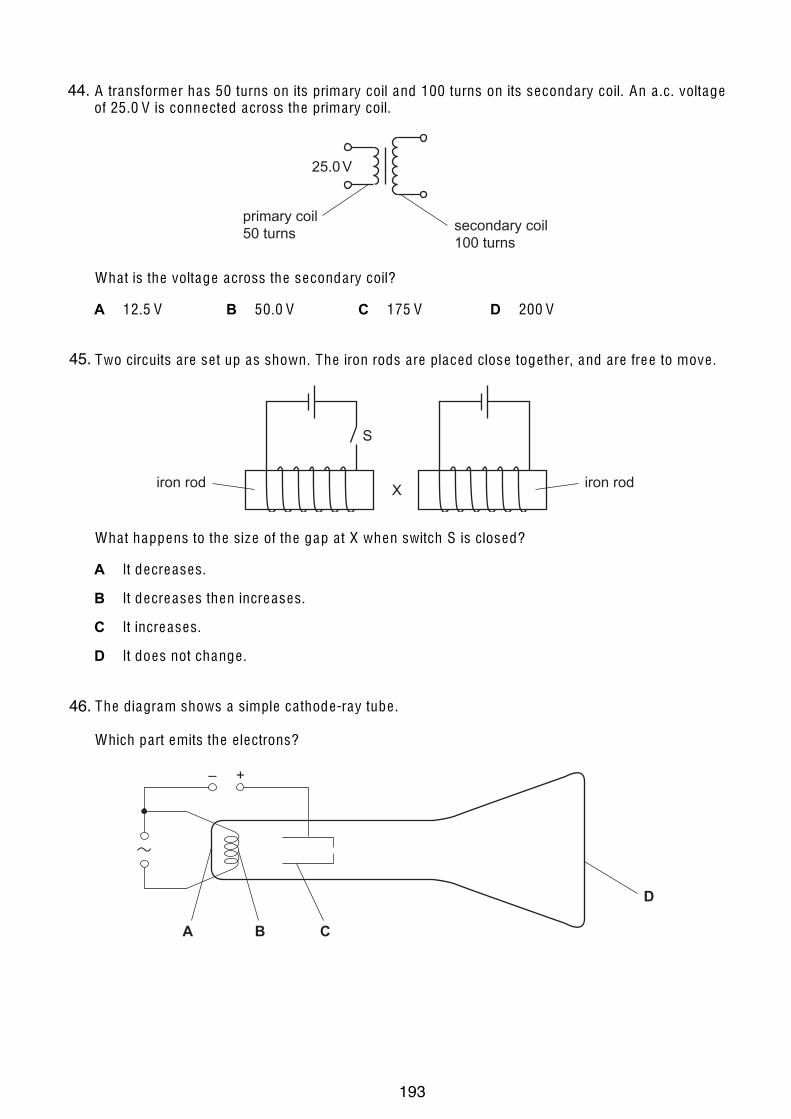
16
© U CLE S 2005 0625/01/M/J/05
35 A transformer has 50 turns on its primary coil and 100 turns on its secondary coil. An a .c. voltage of 25.0 V is connected across the primary coil.
25.0 V
primary coil50 turns secondary coil
100 turns
Wha t is the voltage across the secondary coil?
A 12.5 V B 50.0 V C 175 V D 200 V 36 Two circuits are se t up as shown. The iron rods are placed close toge ther, and are free to move .
X
S
iron rod iron rod
Wha t happens to the size of the gap a t X when switch S is closed?
A It decreases.
B It decreases then increases.
C It increases.
D It does not change . 37 The diagram shows a simple ca thode-ray tube .
Which part emits the e lectrons?
+–
A B C
D
44.
45.
46.
193
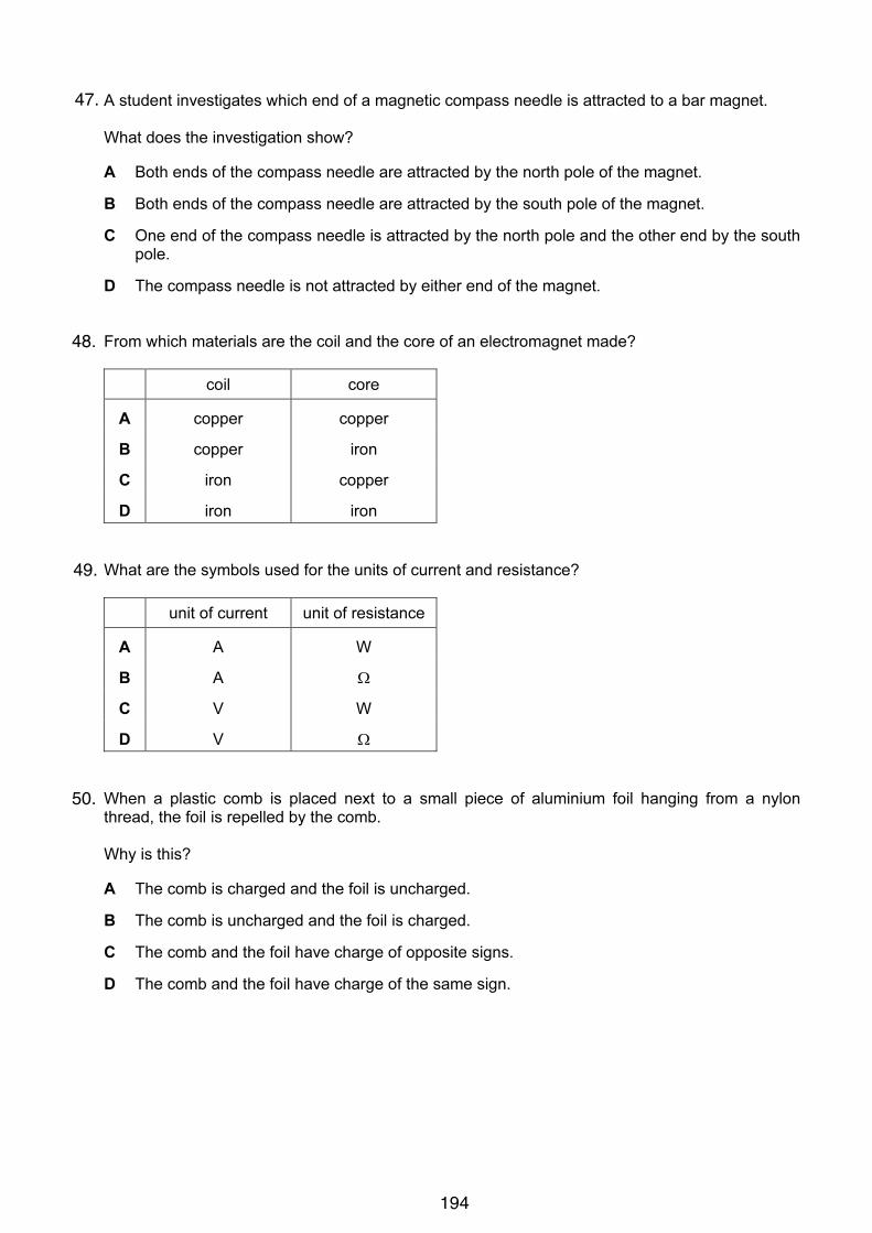
11
© UCLES 2006 0625/01/M/J/06 [Turn over
26 A student investigates which end of a magnetic compass needle is attracted to a bar magnet.
What does the investigation show?
A Both ends of the compass needle are attracted by the north pole of the magnet.
B Both ends of the compass needle are attracted by the south pole of the magnet.
C One end of the compass needle is attracted by the north pole and the other end by the south
pole.
D The compass needle is not attracted by either end of the magnet.
27 From which materials are the coil and the core of an electromagnet made?
coil core
A copper copper
B copper iron
C iron copper
D iron iron
28 What are the symbols used for the units of current and resistance?
unit of current unit of resistance
A A W
B A !
C V W
D V !
29 When a plastic comb is placed next to a small piece of aluminium foil hanging from a nylon
thread, the foil is repelled by the comb.
Why is this?
A The comb is charged and the foil is uncharged.
B The comb is uncharged and the foil is charged.
C The comb and the foil have charge of opposite signs.
D The comb and the foil have charge of the same sign.
47.
48.
49.
50.
194
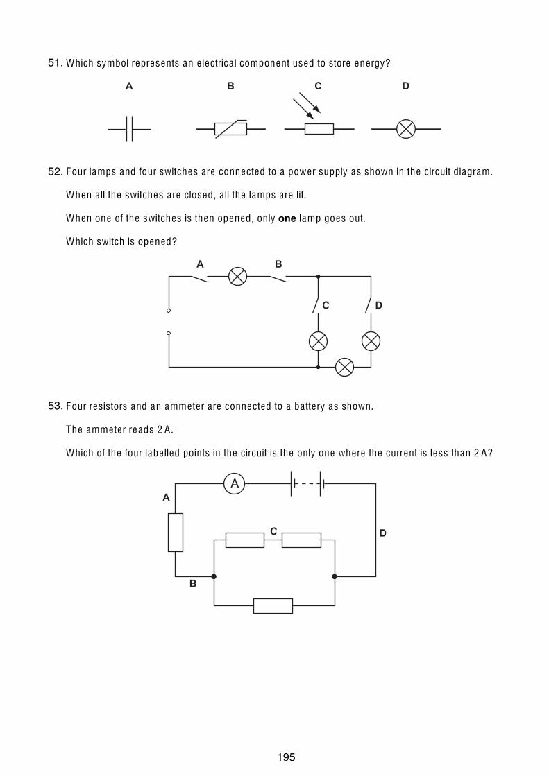
12
© UCLES 2006 0625/01/M/J/06
30 Which symbol represents an e lectrica l component used to store energy?
BA C D
31 Four lamps and four switches are connected to a power supply as shown in the circuit diagram.
When a ll the switches are closed, a ll the lamps are lit.
When one of the switches is then opened, only one lamp goes out.
Which switch is opened?
A B
C D
32 Four resistors and an amme ter are connected to a ba ttery as shown.
The amme ter reads 2 A .
Which of the four labe lled points in the circuit is the only one where the current is less than 2 A?
B
A
C D
A
51.
52.
53.
195

13
© U CLE S 2006 0625/01/M/J/06 [Turn over
33 Why is a fuse used in an electrical circuit in a house?
A to increase the circuit resistance
B to keep the power used to a minimum value
C to prevent a short-circuit from occurring
D to stop the cables from carrying too much current
34 An electric power tool is being used outdoors in a shower of rain.
What is the greatest hazard to the user?
A The cable gets hot and causes burns.
B The circuit-breaker cuts off the current.
C The current passes through water and causes a shock.
D The tool rusts.
35 A current-carrying coil in a magnetic field experiences a turning effect.
N S
variable power supply
How can the turning effect be increased?
A increase the number of turns on the coil
B reduce the size of the current
C reverse the direction of the magnetic field
D use thinner wire for the coil
54.
55.
56.
196

14
© UCLES 2006 0625/01/M/J/06
36 A transformer is to be used to produce a 6 V output from a 24 V input.
24 V 6 V
coil Ycoil X
What are suitable numbers of turns for coil X and for coil Y?
number of turns
on coil X
number of turns
on coil Y
A 240 60
B 240 240
C 240 960
D 960 60
37 A cathode-ray tube has an anode and an earthed cathode.
Which line in the table shows the charge and the temperature of the anode?
anode charge anode temperature
A negative cool
B negative hot
C positive cool
D positive hot
57.
58.
197

iGCSE PhysicsPast Paper QuestionsPaper 3 Compilation
Electricity & Magnetism
198

9
0625/3/M/J/02 [Turn over
7 (a) Two non-conducting spheres, made of different materials, are initially uncharged. Theyare rubbed together. This causes one of the spheres to become positively charged andone negatively charged.
Describe, in terms of electron movement, why the spheres become charged.
..........................................................................................................................................
..........................................................................................................................................
..................................................................................................................................... [2]
(b) Once charged, the two spheres are separated, as shown in Fig. 7.1.
Fig. 7.1
On Fig. 7.1, draw the electric field between the two spheres. Indicate by arrows thedirection of the electric field lines. [2]
(c) A conducting wire attached to a negatively charged metal object is connected to earth.This allows 2.0 ! 1010 electrons, each carrying a charge of 1.6 ! 10–19 C, to flow toearth in 1.0 ! 10–3 s.
Calculate
(i) the total charge that flows,
charge .....................................
(ii) the average current in the wire.
current .....................................[3]
++++
+++ ––
––
–––
ForExaminer’s
Use1.
199

10
0625/3/M/J/02
8 Fig. 8.1 shows a transformer and a rectifier used in a battery charging circuit for a 12 Vbattery.
Fig. 8.1
(a) The transformer produces an output of 15 V across the secondary coil.
Calculate a suitable turns ratio for the transformer.
turns ratio = ................................ [2]
(b) Fig. 8.2 shows the 15 V output across the secondary coil.
Fig. 8.2
On the same axes, sketch the graph of the potential difference across the terminals T1and T2 before the battery is connected. [2]
(c) Explain how the circuit converts an a.c. supply into a d.c. output.
..........................................................................................................................................
..........................................................................................................................................
..................................................................................................................................... [2]
(d) On Fig. 8.1, draw in a battery connected so that it may be charged. [1]
time
potentialdifference
240V a.c.
primary secondary
T1
T2
ForExaminer’s
Use2.
200

11
0625/3/M/J/02 [Turn over
(e) When fully charged, the 12V battery can supply a current of 2.0 A for 30 hours (1.08 ×10⁵ s).
Calculate
(i) the battery power when supplying a current of 2.0 A,
power = ......................................
(ii) the total energy that the battery will supply during the 30 hours.
energy = ......................................[4]
9 Fig. 9.1 shows three resistors connected across a low voltage d.c. supply, and a c.r.o.
Fig. 9.1
(a) Explain how you would use a 1 V d.c. supply to calibrate the c.r.o.
..........................................................................................................................................
..........................................................................................................................................
..................................................................................................................................... [2]
(b) On Fig. 9.1, draw in the connections between the c.r.o. and the circuit so that thepotential difference between points C and D may be measured. [2]
(c) The potential differences between A and F, B and C, C and D, and D and E aremeasured.
State the relationship between them.
..........................................................................................................................................
......................................................................................................................................[2]
Y input
A F
B C D E
d.c.supply
ForExaminer’s
Use
3.
201

9
0625/3/M/J/03 [Turn over
8 Fig. 8.1 shows a battery with a resistor connected across its terminals. The e.m.f. of thebattery is 6.0 V.
Fig. 8.1
The battery causes 90 C of charge to flow through the circuit in 45 s.
(a) Calculate
(i) the current in the circuit,
current = ..................................
(ii) the resistance of the circuit,
resistance = ..................................
(iii) the electrical energy transformed in the circuit in 45 s.
energy = ..................................[6]
(b) Explain what is meant by the term e.m.f. of the battery.
..........................................................................................................................................
..........................................................................................................................................
......................................................................................................................................[2]
6.0V
ForExaminer’s
Use4.
202

10
0625/3/M/J/03
9 A transformer has an output of 24 V when supplying a current of 2.0 A. The current in theprimary coil is 0.40 A and the transformer is 100% efficient.
(a) Calculate
(i) the power output of the transformer,
power = ..................................
(ii) the voltage applied across the primary coil.
voltage = ..................................[4]
(b) Explain
(i) what is meant by the statement that the transformer is 100% efficient,
...................................................................................................................................
...................................................................................................................................
...................................................................................................................................
(ii) how the transformer changes an input voltage into a different output voltage.
...................................................................................................................................
...................................................................................................................................
...................................................................................................................................
...................................................................................................................................[4]
ForExaminer’s
Use5.
203

11
0625/3/M/J/03 [Turn over
10 Fig. 10.1 and Fig. 10.2 show two views of a vertical wire carrying a current up through ahorizontal card. Points P and Q are marked on the card.
Fig. 10.1 Fig. 10.2
(a) On Fig. 10.2,
(i) draw a complete magnetic field line (line of force) through P and indicate itsdirection with an arrow,
(ii) draw an arrow through Q to indicate the direction in which a compass placed at Qwould point.
[3]
(b) State the effect on the direction in which compass Q points of
(i) increasing the current in the wire,
...................................................................................................................................
(ii) reversing the direction of the current in the wire.
...................................................................................................................................[2]
(c) Fig. 10.3 shows the view from above of another vertical wire carrying a current upthrough a horizontal card. A cm grid is marked on the card. Point W is 1 cm verticallyabove the top surface of the card.
Fig. 10.3
State the magnetic field strength at S, T and W in terms of the magnetic field strengthat R. Use one of the alternatives, weaker, same strength or stronger for each answer.
at S ........................................................................
at T ........................................................................
at W........................................................................ [3]
R S
T
W
verticalwire carryingcurrent
P Qverticalwire
view from above the card
ForExaminer’s
Use6.
204

10
0625/03 M/J/04
8 Fig. 8.1 shows a 240 V a.c. mains circuit to which a number of appliances are connected andswitched on.
Fig. 8.1
(a) Calculate the power supplied to the circuit.
power = …………..[1]
(b) The appliances are connected in parallel.
(i) Explain what connected in parallel means.
...................................................................................................................................
...................................................................................................................................
(ii) State two advantages of connecting the appliances in parallel rather than in series.
advantage 1 ...............................................................................................................
advantage 2 ...............................................................................................................[3]
(c) Calculate
(i) the current in the refrigerator,
current = …………..
(ii) the energy used by the fan in 3 hours,
energy = …………..
(iii) the resistance of the filament of one lamp.
resistance = …………..[7]
1.2 kW 200 W60 W 60 W
refrigeratorfan240 V a.c.
ForExaminer’s
Use
© UCLES 2004
7.
205
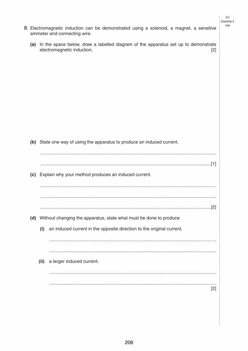
11
0625/03 M/J/04 [Turn over
9 Electromagnetic induction can be demonstrated using a solenoid, a magnet, a sensitiveammeter and connecting wire.
(a) In the space below, draw a labelled diagram of the apparatus set up to demonstrateelectromagnetic induction. [2]
(b) State one way of using the apparatus to produce an induced current.
..........................................................................................................................................
......................................................................................................................................[1]
(c) Explain why your method produces an induced current.
..........................................................................................................................................
..........................................................................................................................................
......................................................................................................................................[2]
(d) Without changing the apparatus, state what must be done to produce
(i) an induced current in the opposite direction to the original current,
...................................................................................................................................
...................................................................................................................................
(ii) a larger induced current.
...................................................................................................................................
...................................................................................................................................[2]
ForExaminer’s
Use
© UCLES 2004
8.
206
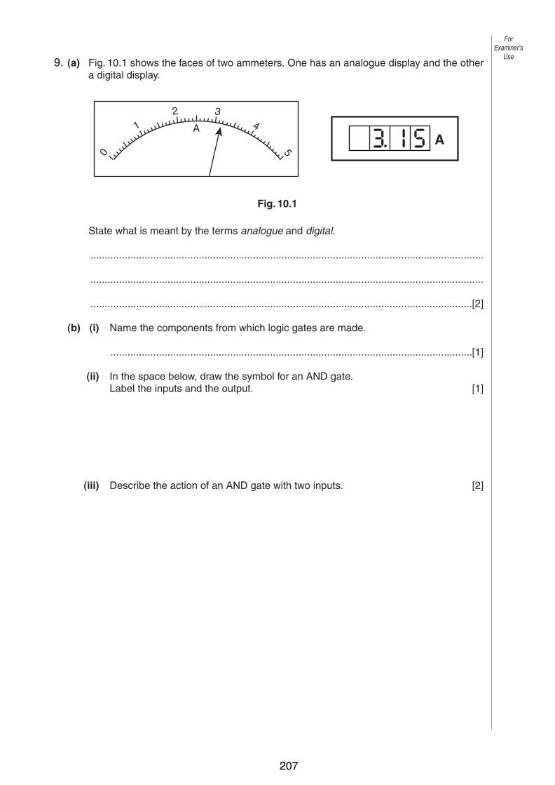
12
0625/03 M/J/04
10 (a) Fig. 10.1 shows the faces of two ammeters. One has an analogue display and the othera digital display.
Fig. 10.1
State what is meant by the terms analogue and digital.
..........................................................................................................................................
..........................................................................................................................................
......................................................................................................................................[2]
(b) (i) Name the components from which logic gates are made.
...............................................................................................................................[1]
(ii) In the space below, draw the symbol for an AND gate.Label the inputs and the output. [1]
(iii) Describe the action of an AND gate with two inputs. [2]
2 34
5
1
0
AA
ForExaminer’s
Use
© UCLES 2004
9.
207
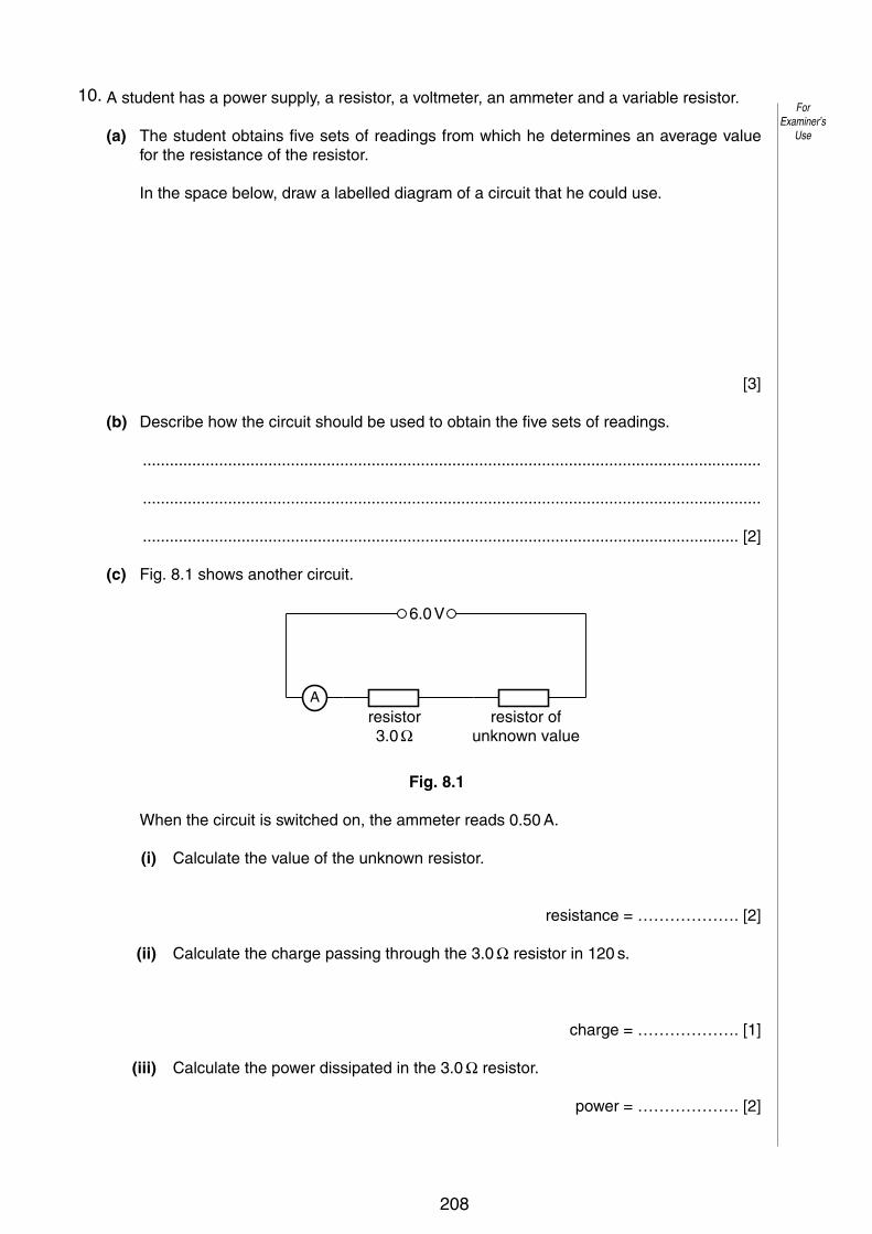
11
0625/03/M/J/05 [Turn over
8 A student has a power supply, a resistor, a voltmeter, an ammeter and a variable resistor.
(a) The student obtains five sets of readings from which he determines an average valuefor the resistance of the resistor.
In the space below, draw a labelled diagram of a circuit that he could use.
[3]
(b) Describe how the circuit should be used to obtain the five sets of readings.
..........................................................................................................................................
..........................................................................................................................................
..................................................................................................................................... [2]
(c) Fig. 8.1 shows another circuit.
Fig. 8.1
When the circuit is switched on, the ammeter reads 0.50 A.
(i) Calculate the value of the unknown resistor.
resistance = ………………. [2]
(ii) Calculate the charge passing through the 3.0 ! resistor in 120 s.
charge = ………………. [1]
(iii) Calculate the power dissipated in the 3.0 ! resistor.
power = ………………. [2]
6.0 V
resistor3.0 !
resistor ofunknown value
A
ForExaminer’s
Use
© UCLES 2005
10.
208
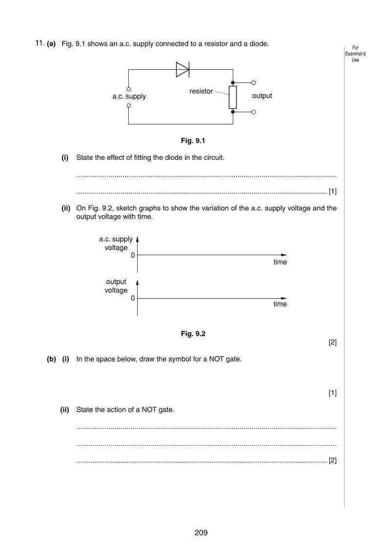
12
0625/03/M/J/05
9 (a) Fig. 9.1 shows an a.c. supply connected to a resistor and a diode.
Fig. 9.1
(i) State the effect of fitting the diode in the circuit.
...................................................................................................................................
.............................................................................................................................. [1]
(ii) On Fig. 9.2, sketch graphs to show the variation of the a.c. supply voltage and theoutput voltage with time.
Fig. 9.2[2]
(b) (i) In the space below, draw the symbol for a NOT gate.
[1]
(ii) State the action of a NOT gate.
...................................................................................................................................
...................................................................................................................................
.............................................................................................................................. [2]
a.c. supplyvoltage
time
time
0
0
outputvoltage
a.c. supply outputresistor
ForExaminer’s
Use
© UCLES 2005
11.
209

14
0625/03/M/J/05
11 Fig. 11.1 shows a flexible wire hanging between two magnetic poles. The flexible wire isconnected to a 12 V d.c. supply that is switched off.
Fig. 11.1
(a) Explain why the wire moves when the supply is switched on.
..........................................................................................................................................
..........................................................................................................................................
..................................................................................................................................... [2]
(b) State the direction of the deflection of the wire.
..........................................................................................................................................
..................................................................................................................................... [2]
(c) When the wire first moves, energy is changed from one form to another. State these twoforms of energy.
from ........................................................... to ............................................................ [1]
wire fixed here
wire fixed here
12 V d.c.+
N S–
flexible wire hangingbetween magnetic poles
ForExaminer’s
Use
© UCLES 2005
12.
210

15
0625/03/M/J/05
(d) Fig. 11.2 shows the flexible wire made into a rigid rectangular coil and mounted on anaxle.
Fig. 11.2
(i) Add to the diagram an arrangement that will allow current to be fed into the coilwhilst allowing the coil to turn continuously. Label the parts you have added. [1]
(ii) Briefly explain how your arrangement works.
...................................................................................................................................
.............................................................................................................................. [2]
axle
magnetic pole
magnetic pole
axle
N N
S S
coil
ForExaminer’s
Use
© UCLES 2005
211

9
0625/03/M/J/06 [Turn over
ForExaminer’s
Use
© UCLES 2006
8 Fig. 8.1 shows an electrical circuit.
12.0 V d.c.
4.0 !
R A C B
sliding contact
one metre resistance wire
Fig. 8.1
The resistance of the lamp is 4.0 Λ when it is at its normal brightness.
(a) The lamp is rated at 6.0 V, 9.0 W. Calculate the current in the lamp when it is at its normal brightness.
current = ........................[2]
(b) The sliding contact C is moved to A. The lamp lights at its normal brightness. Calculate
(i) the total circuit resistance,
resistance = ........................[1]
(ii) the potential difference across the 4.0 Λ resistor R.
potential difference = ........................[1]
(c) The sliding contact C is moved from A to B.
(i) Describe any change that occurs in the brightness of the lamp.
..............................................................................................................................[1]
(ii) Explain your answer to (i).
..................................................................................................................................
..............................................................................................................................[2]
(d) The 1 m wire between A and B, as shown in Fig. 8.1, has a resistance of 2.0 Λ. Calculate the resistance between A and B when
(i) the 1 m length is replaced by a 2 m length of the same wire,
resistance = ........................[1]
(ii) the 1 m length is replaced by a 1 m length of a wire of the same material but of only half the cross-sectional area.
resistance = ........................[1]
13.
212

10
0625/03/M/J/06
ForExaminer’s
Use
© UCLES 2006
9 A transformer is needed to step down a 240 V a.c. supply to a 12 V a.c. output.
(a) In the space below, draw a labelled diagram of a suitable transformer. [3]
(b) Explain
(i) why the transformer only works on a.c.,
..................................................................................................................................
..............................................................................................................................[1]
(ii) how the input voltage is changed to an output voltage.
..................................................................................................................................
..................................................................................................................................
..............................................................................................................................[2]
(c) The output current is 1.5 A.
Calculate
(i) the power output,
power = ........................[1]
(ii) the energy output in 30 s.
energy = ........................[1]
14.
213

11
0625/03/M/J/06 [Turn over
ForExaminer’s
Use
© UCLES 2006
10 (a) Fig. 10.1 shows a positively charged plastic rod, a metal plate resting on an insulator, and a lead connected to earth.
metal plateinsulator
positively chargedplastic rod
lead connected to earth
Fig. 10.1
Describe how the metal plate may be charged by induction.
..........................................................................................................................................
..........................................................................................................................................
......................................................................................................................................[3]
(b) An electrostatic generator sets up a current of 20 mA in a circuit.
Calculate
(i) the charge flowing through the circuit in 15 s,
charge = ............................
(ii) the potential difference across a 10 kΛ resistor in the circuit.
potential difference = ............................ [3]
15.
214
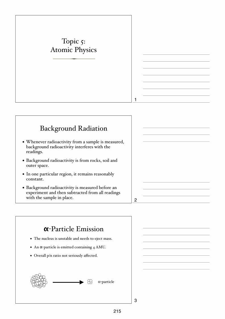
Topic 5:Atomic Physics
Background Radiation
• Whenever radioactivity from a sample is measured, background radioactivity interferes with the readings.
• Background radioactivity is from rocks, soil and outer space.
• In one particular region, it remains reasonably constant.
• Background radioactivity is measured before an experiment and then subtracted from all readings with the sample in place.
α-Particle Emission• The nucleus is unstable and needs to eject mass.
• An α-particle is emitted containing 4 AMU.
• Overall p/n ratio not seriously affected.
α-particle
1
2
3
215
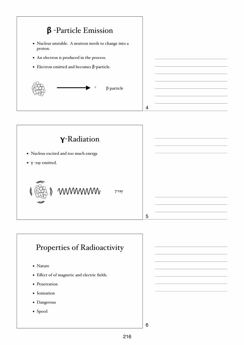
β -Particle Emission• Nucleus unstable. A neutron needs to change into a
proton.
• An electron is produced in the process.
• Electron emitted and becomes β-particle.
β-particle
γ-Radiation
• Nucleus excited and too much energy.
• γ -ray emitted.
γ-ray
Properties of Radioactivity
• Nature
• Effect of of magnetic and electric fields.
• Penetration
• Ionisation
• Dangerous
• Speed
4
5
6
216
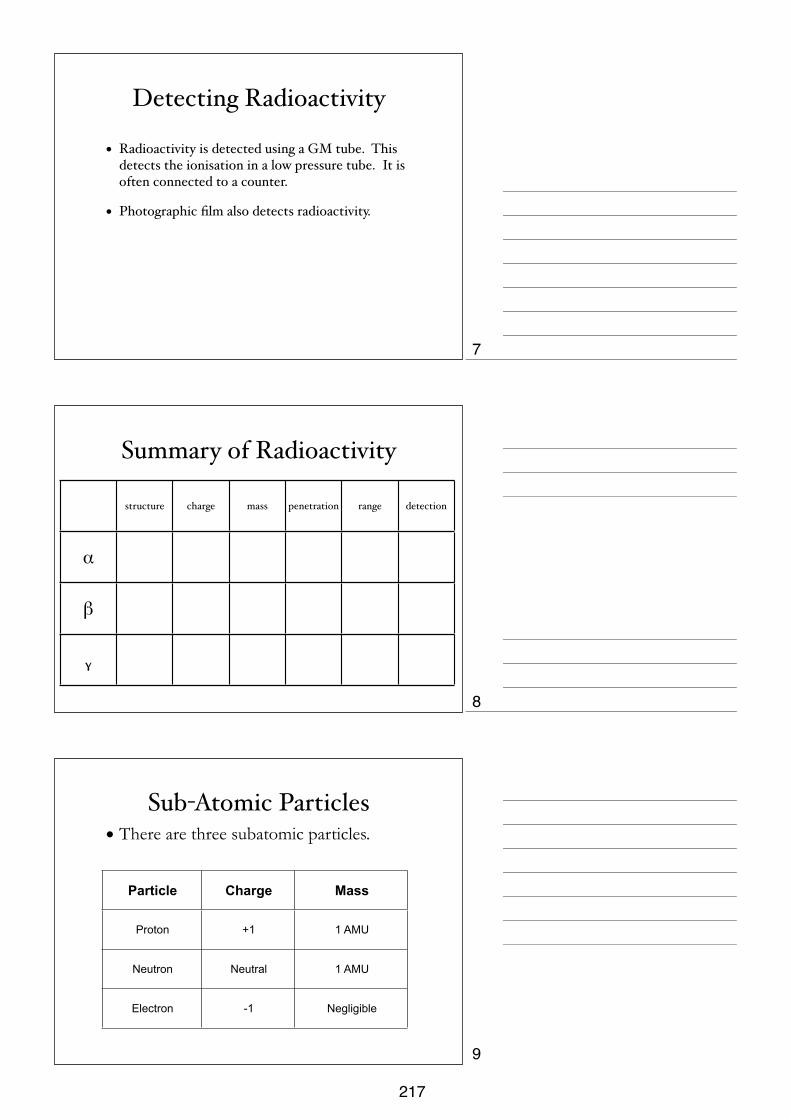
Detecting Radioactivity
• Radioactivity is detected using a GM tube. This detects the ionisation in a low pressure tube. It is often connected to a counter.
• Photographic film also detects radioactivity.
Summary of Radioactivity
structure charge mass penetration range detection
α
β
ᵧ
Sub-Atomic Particles• There are three subatomic particles.
Particle Charge Mass
Proton +1 1 AMU
Neutron Neutral 1 AMU
Electron -1 Negligible
7
8
9
217

Rutherford Scattering
• Large + α-particles are fired at gold atoms.
• Most of the particles pass straight through the gold.
• Some particles are deflected.
• Some particles actually ‘bounce’ back towards the source.
Rutherford’s Nuclear Model
• Rutherford explained these results using the nuclear model of the atom. This says:
• Most of the atom is empty space.
• There is a positively charged nucleus.
• Electrons orbit the nucleus in circular paths.
Gold Nucleus
Paths of α-particles
Nuclear Notation
• Proton number (or Atomic Number) (Z) is the number of protons in the Nucleus.
• Nucleon Number (or Mass Number) (A) is the total number of particles in the nucleus (protons + neutrons)
XA
Z
10
11
12
218

Isotopes
• Isotopes are two nuclei with the same number of electrons, the same numbers of protons, but different numbers of neutrons.
• They are chemically identical, but physically different (density, radioactivity).
Half-Life• Over time, the number of particles in a radioactive
sample decreases, and so does the activity of the sample.
• This produces an exponential decay curve.
• The time taken for the number of radioactive nuclei to half is called the ‘half-life’.
• It is also the time taken for the activity of THE SAMPLE to half.
Decay Curve
0
250000
500000
750000
1000000
0 25 50 75 100
Num
ber o
f Par
ticle
s
TimeA similar shaped curve is produced for the activity of the sample
against time with the same half-life.
13
14
15
219
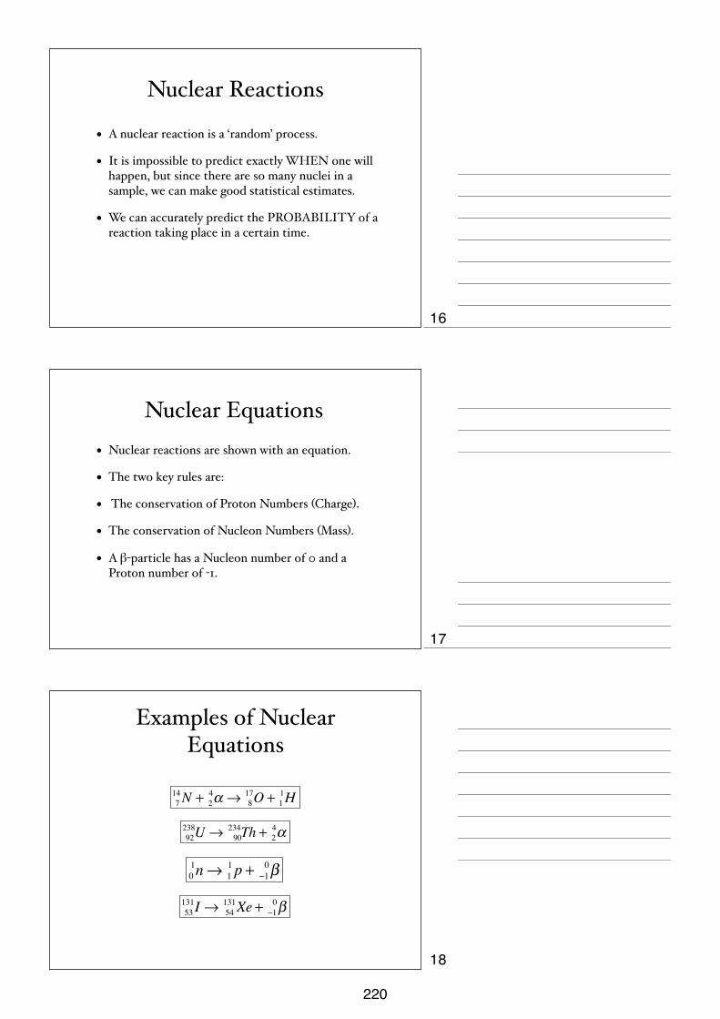
Nuclear Reactions
• A nuclear reaction is a ‘random’ process.
• It is impossible to predict exactly WHEN one will happen, but since there are so many nuclei in a sample, we can make good statistical estimates.
• We can accurately predict the PROBABILITY of a reaction taking place in a certain time.
Nuclear Equations• Nuclear reactions are shown with an equation.
• The two key rules are:
• The conservation of Proton Numbers (Charge).
• The conservation of Nucleon Numbers (Mass).
• A β-particle has a Nucleon number of 0 and a Proton number of -1.
Examples of Nuclear Equations
714N + 2
4α → 817O + 1
1H
92238U → 90
234Th + 24α
01n→ 1
1p + −10β
53131I → 54
131Xe + −10β
16
17
18
220

Nuclear and Atomic Physics Quantity and
symbol Word equation / definition Symbol equation charge
Proton, p Positive particle found in the nucleus of an atom.
11p +1
Electron, e Negative particle found in orbits around the nucleus of an atom.
0-1e -1
Neutron, n Neutral particle found in the nucleus 10n 0
Nucleon Any particle found in the nucleus of an atom.
Nuclide notation A
ZX Where X is the symbol for the nuclide
Proton Number, Z The number of protons in the nucleus Nucleon Number, A The number of nucleons in the nucleus
Alpha Particle, α A helium nucleus, consisting of 2 protons and 2 neutrons, given out when a nucleus decays
42 α +2
Beta Particle, β
A high speed electron, given off when a neutron in the nucleus decays in to a proton and beta particle. The proton remains in the nucleus.
0-1β -1
Gamma Ray, γ Electromagnetic radiation, sometimes given off when a nucleus decays.
00γ 0
Background Radiation
There is a small amount of radiation around us all the time because of radioactive materials in the environment. It is mainly from sources such as soil, rock, air, building materials, food and drink, and even space.
Radioactive Decay Radioactive decay is a random, spontaneous event that cannot be change by chemical or physical methods.
Alpha Decay AZX → A-4
Z-2Y +42 α
Beta Decay AZX → AZ+1Y + 0-1β
Gamma Decay AZX → AZX + 00γ
Half Life The half life of a radioactive source is the time taken for half the available particle to decay. It is constant for a source.
Isotopes
The atoms of one element are not all exactly alike. Some may have more neutrons than others. These different versions of the element are called isotopes. They have identical chemical properties, although the atoms have different masses. Isotopes have the same proton number, but different neutron numbers
221

iGCSE PhysicsPast Paper QuestionsPaper 1 Compilation
Atomic & Nuclear Physics
222

17
0625/1/M/J/02
39 The diagram shows a radioactivity experiment.
When a piece of paper is used as the absorber, the count rate drops to the background countrate.
What radiation is the source emitting?
A alpha only
B beta only
C gamma only
D alpha, beta and gamma
40 2210Ne represents an atom of neon.
How many neutrons does it have?
A 10 B 12 C 22 D 32
absorber counter
radiation detectorsource
16
0625/1/M/J/02
36 The diagram shows part of a circuit used to switch street lamps on and off automatically.
What is the effect on the light-dependent resistor (LDR) when it gets dark?
37 An alternating potential difference (p.d.) is applied to the Y-plates of a cathode-ray oscilloscope.The time-base is turned off.
Which of the following patterns would appear on the screen?
38 What is a beta-particle?
A a helium nucleus
B a high-energy electron
C four protons
D two neutrons
A B C D
+
–
LDR
resistance of LDR p.d. across LDR
A decreases decreases
B decreases increases
C increases decreases
D increases increases
1.
2.
3.
4.
223

17
0625/1/M/J/02
39 The diagram shows a radioactivity experiment.
When a piece of paper is used as the absorber, the count rate drops to the background countrate.
What radiation is the source emitting?
A alpha only
B beta only
C gamma only
D alpha, beta and gamma
40 2210Ne represents an atom of neon.
How many neutrons does it have?
A 10 B 12 C 22 D 32
absorber counter
radiation detectorsource
5.
6.
7.
224

18
0625/01/M/J/03
40 An atom of lithium contains three protons and three electrons.
The nucleon number (mass number) of the atom is 7.
How many neutrons are there in the atom?
A 3 B 4 C 7 D 10
17
0625/01/M/J/03 [Turn over
37 An electrical component X is placed in water, as shown.
When the temperature of the water is increased, the reading on the ammeter increases.
What is component X?
A a capacitor
B a light-dependent resistor
C a reed relay
D a thermistor
38 Which type of radiation can be stopped by a sheet of paper?
A α-particles
B β-particles
C γ-rays
D X-rays
39 The half-life of a radioactive substance is 5 hours. A sample is tested and found to contain 0.48 gof the substance.
How much of the substance was present in the sample 20 hours before the sample was tested?
A 0.03 g
B 0.12 g
C 1.92 g
D 7.68 g
X
A
thermometer
water
8.
9.
10.
225

18
! U CLE S 2004 0625/01/M/J/04
38 Which line correctly describes -particles?
e lectric charge pene tra tes 1 cmof a luminium?
A nega tive yes
B nega tive no
C positive yes
D positive no
39 A sma ll amount of a radioactive isotope conta ins 72 billion unstable nucle i. The ha lf-life of the isotope is 4 hours.
How many unstable nucle i would rema in a fter 12 hours?
A 6 billion
B 9 billion
C 18 billion
D 24 billion
40 How many nucleons are in a nucleus of K39
19?
A 19 B 20 C 39 D 58
11.
12.
13.
226
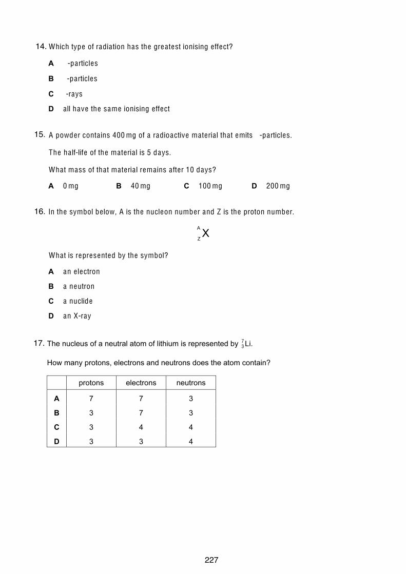
17
© UCLES 2005 0625/01/M/J/05
38 Which type of radia tion has the grea test ionising e ffect?
A -particles
B -particles
C -rays
D a ll have the same ionising e ffect 39 A powder conta ins 400 mg of a radioactive ma teria l tha t emits -particles.
The ha lf-life of the ma teria l is 5 days.
Wha t mass of tha t ma teria l rema ins a fter 10 days?
A 0 mg B 40 mg C 100 mg D 200 mg 40 In the symbol be low, A is the nucleon number and Z is the proton number.
X
A
Z
Wha t is represented by the symbol?
A an e lectron
B a neutron
C a nuclide
D an X-ray
16
Permission to reproduce items where third-party owned material protected by copyright is included has been sought and cleared where possible. Every
reasonable effort has been made by the publisher (UCLES) to trace copyright holders, but if any items requiring clearance have unwittingly been included, the
publisher will be pleased to make amends at the earliest possible opportunity.
University of Cambridge International Examinations is part of the University of Cambridge Local Examinations Syndicate (UCLES), which is itself a department
of the University of Cambridge.
© U CLE S 2006 0625/01/M/J/06
40 The nucleus of a neutral atom of lithium is represented by Li.73
How many protons, electrons and neutrons does the atom contain?
protons electrons neutrons
A 7 7 3
B 3 7 3
C 3 4 4
D 3 3 4
14.
15.
16.
17.
227
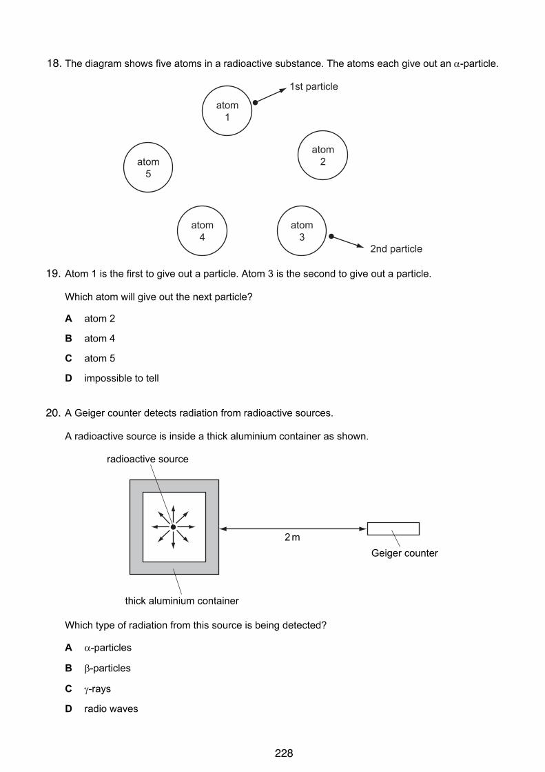
15
© UCLES 2006 0625/01/M/J/06 [Turn over
38 The diagram shows five atoms in a radioactive substance. The atoms each give out an !-particle.
atom1
atom5
atom4
atom3
atom2
1st particle
2nd particle
Atom 1 is the first to give out a particle. Atom 3 is the second to give out a particle.
Which atom will give out the next particle?
A atom 2
B atom 4
C atom 5
D impossible to tell
39 A Geiger counter detects radiation from radioactive sources.
A radioactive source is inside a thick aluminium container as shown.
radioactive source
2 mGeiger counter
thick aluminium container
Which type of radiation from this source is being detected?
A !-particles
B "-particles
C #-rays
D radio waves
18.
19.
20.
228
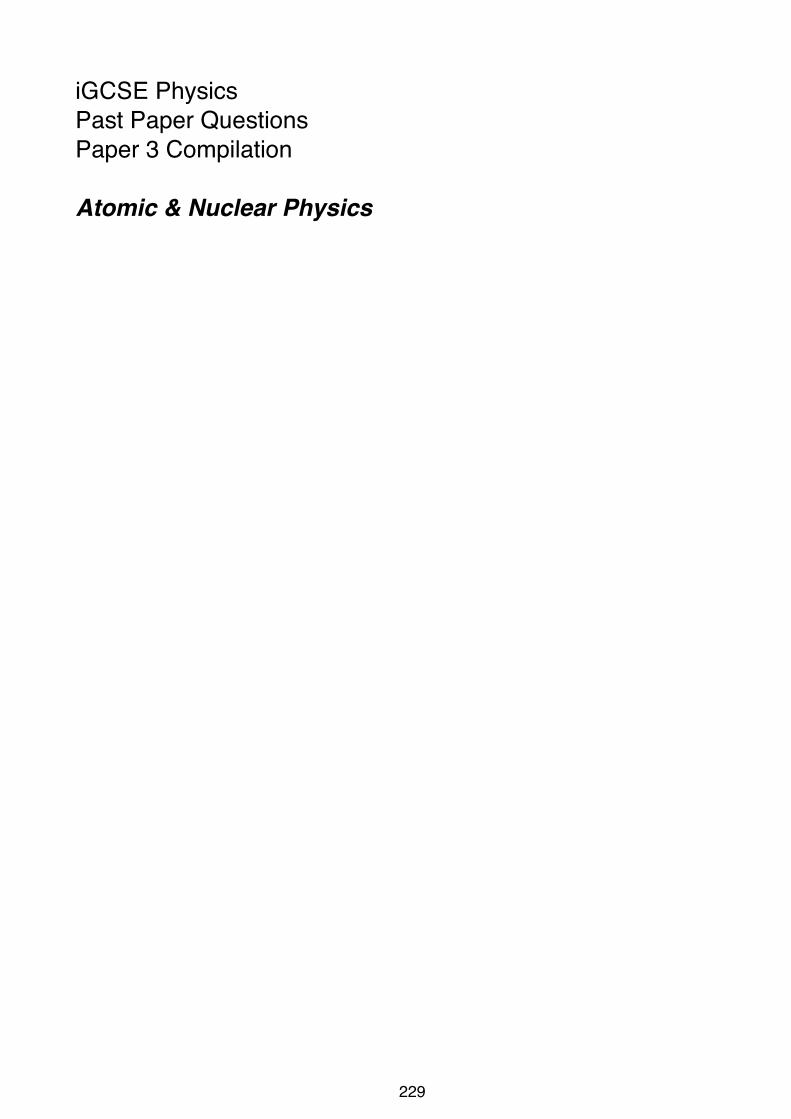
iGCSE PhysicsPast Paper QuestionsPaper 3 Compilation
Atomic & Nuclear Physics
229

12
0625/3/M/J/02
10 Some liquid from an atomic power station is known to be radioactive. A sample of this liquidis tested in a laboratory.
(a) In the space below, draw a labelled diagram of the test apparatus used to verify that!-particles are emitted from the liquid. [2]
(b) Explain how the apparatus may be used to estimate the quantity of !-radiation beingemitted from the sample.
..........................................................................................................................................
..........................................................................................................................................
..........................................................................................................................................
..........................................................................................................................................
..................................................................................................................................... [2]
(c) State any two safety precautions that the technician might take whilst making the test.
precaution 1 .....................................................................................................................
..........................................................................................................................................
precaution 2 .....................................................................................................................
..................................................................................................................................... [2]
ForExaminer’s
Use
230

12
0625/3/M/J/03
11 (a) A radioactive isotope emits only !-particles.
(i) In the space below, draw a labelled diagram of the apparatus you would use toprove that no "-particles or #-radiation are emitted from the isotope.
(ii) Describe the test you would carry out.
...................................................................................................................................
...................................................................................................................................
...................................................................................................................................
...................................................................................................................................
(iii) Explain how your results would show that only !-particles are emitted.
...................................................................................................................................
...................................................................................................................................
...................................................................................................................................[6]
(b) Fig. 11.1 shows a stream of !-particles about to enter the space between the poles of avery strong magnet.
Fig. 11.1
Describe the path of the !-particles in the space between the magnetic poles.
..........................................................................................................................................
..........................................................................................................................................
......................................................................................................................................[3]
N
S!-particles
ForExaminer’s
Use
231
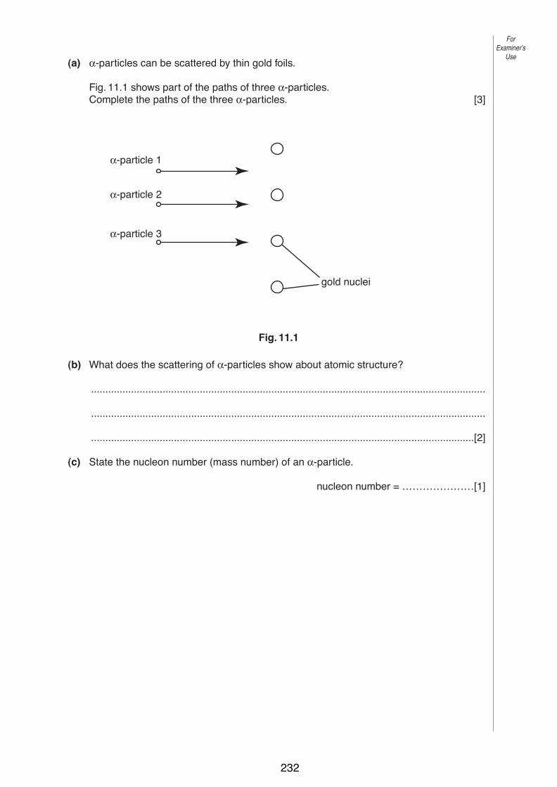
13
0625/03 M/J/04
11 (a) α-particles can be scattered by thin gold foils.
Fig. 11.1 shows part of the paths of three α-particles.Complete the paths of the three α-particles. [3]
Fig. 11.1
(b) What does the scattering of α-particles show about atomic structure?
..........................................................................................................................................
..........................................................................................................................................
......................................................................................................................................[2]
(c) State the nucleon number (mass number) of an α-particle.
nucleon number = …………………[1]
α-particle 1
α-particle 2
α-particle 3
gold nuclei
ForExaminer’s
Use
© UCLES 2004
232
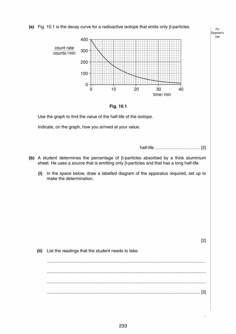
13
0625/03/M/J/05 [Turn over
10 (a) Fig. 10.1 is the decay curve for a radioactive isotope that emits only β-particles.
Fig. 10.1
Use the graph to find the value of the half-life of the isotope.
Indicate, on the graph, how you arrived at your value.
half-life …………………………. [2]
(b) A student determines the percentage of β-particles absorbed by a thick aluminiumsheet. He uses a source that is emitting only β-particles and that has a long half-life.
(i) In the space below, draw a labelled diagram of the apparatus required, set up tomake the determination.
[2]
(ii) List the readings that the student needs to take.
...................................................................................................................................
...................................................................................................................................
...................................................................................................................................
.............................................................................................................................. [3]
0 10
100
0
200
300
400
20time / min
count ratecounts / min
30 40
ForExaminer’s
Use
© UCLES 2005
233

12
0625/03/M/J/06
ForExaminer’s
Use
© UCLES 2006
11 Fig. 11.1 shows a beam of radiation that contains !-particles, "-particles and #-rays. The beam enters a very strong magnetic field shown in symbol form by N and S poles.
beam ofradiation
N
S
Fig. 11.1
Complete the table below.
radiation direction of deflection, if any
charge carried byradiation, if any
!-particles
"-particles
#-rays
[6]
Permission to reproduce items where third-party owned material protected by copyright is included has been sought and cleared where possible. Every reasonable effort has been made by the publisher (UCLES) to trace copyright holders, but if any items requiring clearance have unwittingly been included, the publisher will be pleased to make amends at the earliest possible opportunity.
University of Cambridge International Examinations is part of the University of Cambridge Local Examinations Syndicate (UCLES), which is itself a department of the University of Cambridge.
234
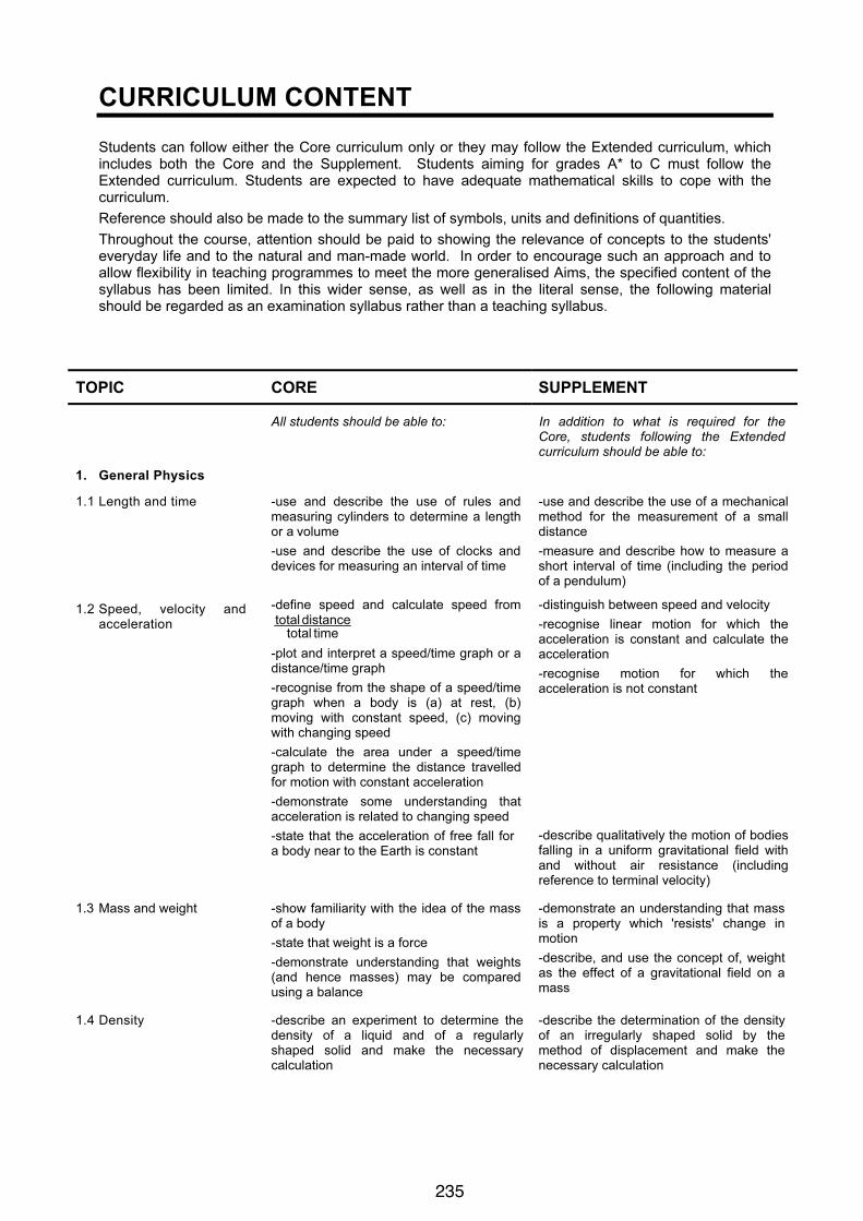
PHYSICS 0625 IGCSE 2007
5
CURRICULUM CONTENT
Students can follow either the Core curriculum only or they may follow the Extended curriculum, which
includes both the Core and the Supplement. Students aiming for grades A* to C must follow the
Extended curriculum. Students are expected to have adequate mathematical skills to cope with the
curriculum.
Reference should also be made to the summary list of symbols, units and definitions of quantities.
Throughout the course, attention should be paid to showing the relevance of concepts to the students'
everyday life and to the natural and man-made world. In order to encourage such an approach and to
allow flexibility in teaching programmes to meet the more generalised Aims, the specified content of the
syllabus has been limited. In this wider sense, as well as in the literal sense, the following material
should be regarded as an examination syllabus rather than a teaching syllabus.
TOPIC CORE SUPPLEMENT
All students should be able to: In addition to what is required for the
Core, students following the Extended
curriculum should be able to:
1. General Physics
1.1 Length and time -use and describe the use of rules and
measuring cylinders to determine a length
or a volume
-use and describe the use of clocks and
devices for measuring an interval of time
-use and describe the use of a mechanical
method for the measurement of a small
distance
-measure and describe how to measure a
short interval of time (including the period
of a pendulum)
1.2 Speed, velocity and
acceleration
-define speed and calculate speed from
time total
distance total
-plot and interpret a speed/time graph or a
distance/time graph
-recognise from the shape of a speed/time
graph when a body is (a) at rest, (b)
moving with constant speed, (c) moving
with changing speed
-calculate the area under a speed/time
graph to determine the distance travelled
for motion with constant acceleration
-demonstrate some understanding that
acceleration is related to changing speed
-state that the acceleration of free fall for
a body near to the Earth is constant
-distinguish between speed and velocity
-recognise linear motion for which the
acceleration is constant and calculate the
acceleration
-recognise motion for which the
acceleration is not constant
-describe qualitatively the motion of bodies
falling in a uniform gravitational field with
and without air resistance (including
reference to terminal velocity)
1.3 Mass and weight
-show familiarity with the idea of the mass
of a body
-state that weight is a force
-demonstrate understanding that weights
(and hence masses) may be compared
using a balance
-demonstrate an understanding that mass
is a property which 'resists' change in
motion
-describe, and use the concept of, weight
as the effect of a gravitational field on a
mass
1.4 Density -describe an experiment to determine the
density of a liquid and of a regularly
shaped solid and make the necessary
calculation
-describe the determination of the density
of an irregularly shaped solid by the
method of displacement and make the
necessary calculation
235

PHYSICS 0625 IGCSE 2007
6
TOPIC CORE SUPPLEMENT
1.5 Forces
(a) Effects of forces
-state that a force may produce a change
in size and shape of a body
-plot extension/load graphs and describe
the associated experimental procedure
-describe the ways in which a force may
change the motion of a body
-find the resultant of two or more forces
acting along the same line
-interpret extension/load graphs
-state Hooke’s Law and recall and use the
expression F = k x
-recognise the significance of the term 'limit
of proportionality' for an extension/load
graph
-recall and use the relation between force,
mass and acceleration (including the
direction)
-describe, qualitatively, motion in a curved
path due to a perpendicular force
(F = mv2
/ r is not required)
(b) Turning effect -describe the moment of a force as a
measure of its turning effect and give
everyday examples
-describe, qualitatively, the balancing of a
beam about a pivot
-perform and describe an experiment
(involving vertical forces) to verify that
there is no net moment on a body in
equilibrium
-apply the idea of opposing moments to
simple systems in equilibrium
(c) Conditions for
equilibrium
-state that, when there is no resultant force
and no resultant turning effect, a system is
in equilibrium
(d) Centre of mass -perform and describe an experiment to
determine the position of the centre of
mass of a plane lamina
-describe qualitatively the effect of the
position of the centre of mass on the
stability of simple objects
(e) Scalars and vectors -demonstrate an understanding of the
difference between scalars and vectors
and give common examples
-add vectors by graphical representation to
determine a resultant
-determine graphically a resultant of two
vectors
1.6 Energy, work and power
(a) Energy
-demonstrate an understanding that an
object may have energy due to its motion
or its position, and that energy may be
transferred and stored
-give examples of energy in different
forms, including kinetic, gravitational,
chemical, strain, nuclear, internal,
electrical, light and sound
-give examples of the conversion of energy
from one form to another and of its transfer
from on place to another
-apply the principle of energy conservation
to simple examples
-recall and use the expressions
k.e.= ! mv2
and p.e. = mgh
236
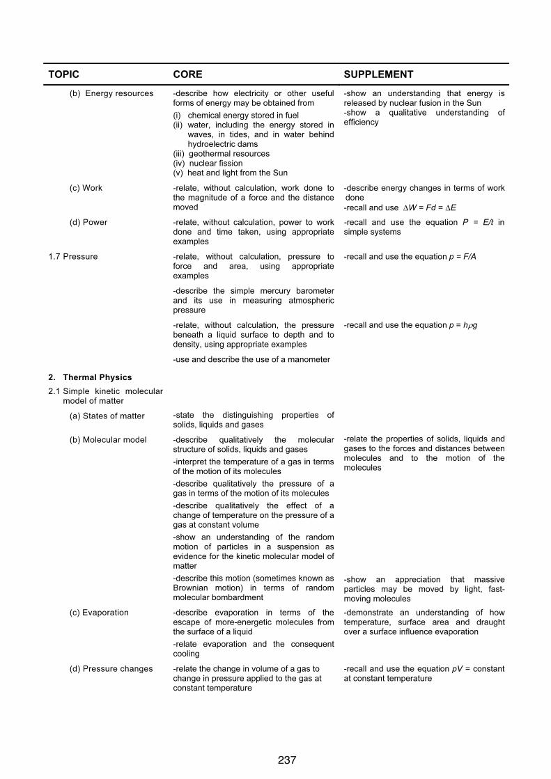
PHYSICS 0625 IGCSE 2007
7
TOPIC CORE SUPPLEMENT
(b) Energy resources -describe how electricity or other useful
forms of energy may be obtained from
(i) chemical energy stored in fuel
(ii) water, including the energy stored in
waves, in tides, and in water behind
hydroelectric dams
(iii) geothermal resources
(iv) nuclear fission
(v) heat and light from the Sun
-show an understanding that energy is
released by nuclear fusion in the Sun
-show a qualitative understanding of
efficiency
(c) Work -relate, without calculation, work done to
the magnitude of a force and the distance
moved
-describe energy changes in terms of work
done
-recall and use !W = Fd = !E
(d) Power -relate, without calculation, power to work
done and time taken, using appropriate
examples
-recall and use the equation P = E/t in
simple systems
1.7 Pressure -relate, without calculation, pressure to
force and area, using appropriate
examples
-describe the simple mercury barometer
and its use in measuring atmospheric
pressure
-relate, without calculation, the pressure
beneath a liquid surface to depth and to
density, using appropriate examples
-use and describe the use of a manometer
-recall and use the equation p = F/A
-recall and use the equation p = h!g
2. Thermal Physics
2.1 Simple kinetic molecular
model of matter
(a) States of matter
-state the distinguishing properties of
solids, liquids and gases
(b) Molecular model -describe qualitatively the molecular
structure of solids, liquids and gases
-interpret the temperature of a gas in terms
of the motion of its molecules
-describe qualitatively the pressure of a
gas in terms of the motion of its molecules
-describe qualitatively the effect of a
change of temperature on the pressure of a
gas at constant volume
-show an understanding of the random
motion of particles in a suspension as
evidence for the kinetic molecular model of
matter
-describe this motion (sometimes known as
Brownian motion) in terms of random
molecular bombardment
-relate the properties of solids, liquids and
gases to the forces and distances between
molecules and to the motion of the
molecules
-show an appreciation that massive
particles may be moved by light, fast-
moving molecules
(c) Evaporation -describe evaporation in terms of the
escape of more-energetic molecules from
the surface of a liquid
-relate evaporation and the consequent
cooling
-demonstrate an understanding of how
temperature, surface area and draught
over a surface influence evaporation
(d) Pressure changes -relate the change in volume of a gas to
change in pressure applied to the gas at
constant temperature
-recall and use the equation pV = constant
at constant temperature
237

PHYSICS 0625 IGCSE 2007
8
TOPIC CORE SUPPLEMENT
2.2 Thermal properties
(a) Thermal expansion
of solids, liquids and
gases
-describe qualitatively the thermal
expansion of solids, liquids and gases
-identify and explain some of the everyday
applications and consequences of thermal
expansion
-describe qualitatively the effect of a
change of temperature on the volume of a
gas at constant pressure
-show an appreciation of the relative order
of magnitude of the expansion of solids,
liquids and gases
(b) Measurement of
temperature
-appreciate how a physical property which
varies with temperature may be used for
the measurement of temperature and state
examples of such properties
-recognise the need for and identify fixed
points
-describe the structure and action of liquid-
in-glass thermometers
-demonstrate understanding of sensitivity,
range and linearity
-describe the structure of a thermocouple
and show understanding of its use for
measuring high temperatures and those
which vary rapidly
(c) Thermal capacity -relate a rise in temperature of a body to an
increase in internal energy
-show an understanding of the term
thermal capacity -describe an experiment to measure the
specific heat capacity of a substance
(d) Melting and boiling -describe melting and boiling in terms of
energy input without a change in
temperature
-state the meaning of melting point and
boiling point
-describe condensation and solidification
-distinguish between boiling and
evaporation
-use the terms latent heat of vaporisation
and latent heat of fusion and give a
molecular interpretation of latent heat
-describe an experiment to measure
specific latent heats for steam and for ice
2.3 Transfer of thermal
energy
(a) Conduction
-describe experiments to demonstrate the
properties of good and bad conductors of
heat
-give a simple molecular account of heat
transfer in solids
(b) Convection -relate convection in fluids to density
changes and describe experiments to
illustrate convection
(c) Radiation -identify infra-red radiation as part of the
electromagnetic spectrum
-describe experiments to show the
properties of good and bad emitters and
good and bad absorbers of infra-red
radiation
(d) Consequences of
energy transfer
-identify and explain some of the everyday
applications and consequences of
conduction, convection and radiation
3. Properties of waves,
including light and
sound
3.1 General wave properties -describe what is meant by wave motion as
illustrated by vibration in ropes, springs and
by experiments using water waves
-use the term wavefront
-give the meaning of speed, frequency,
wavelength and amplitude
-recall and use the equation v = f !
238

PHYSICS 0625 IGCSE 2007
9
TOPIC CORE SUPPLEMENT
-distinguish between transverse and
longitudinal waves and give suitable
examples
-describe the use of water waves to show
(i) reflection at a plane surface
(ii) refraction due to a change of speed
(iii) diffraction produced by wide and
narrow gaps
-interpret reflection, refraction and
diffraction using wave theory
3.2 Light
(a) Reflection of light -describe the formation, and give the
characteristics, of an optical image by a
plane mirror
-use the law angle of incidence = angle of
reflection
-perform simple constructions,
measurements and calculations
(b) Refraction of light -describe an experimental demonstration of
the refraction of light
-use the terminology for the angle of
incidence i and angle of refraction r and
describe the passage of light through
parallel-sided transparent material
-give the meaning of critical angle
-describe internal and total internal
reflection
-recall and use the definition of refractive
index n in terms of speed
-recall and use the equation sin i /sin r = n
-describe the action of optical fibres
(c) Thin converging
lens
-describe the action of a thin converging
lens on a beam of light
-use the term principal focus and focal
length
-draw ray diagrams to illustrate the
formation of a real image by a single lens
-draw ray diagrams to illustrate the
formation of a virtual image by a single lens
-use and describe the use of a single lens
as a magnifying glass
(d) Dispersion of light -give a qualitative account of the dispersion
of light as illustrated by the action on light
of a glass prism
(e) Electromagnetic
spectrum
-describe the main features of the
electromagnetic spectrum and state that all
e.m. waves travel with the same high
speed in vacuo
-state the approximate value of the speed
of electro-magnetic waves
-use the term monochromatic
3.3 Sound -describe the production of sound by
vibrating sources
-describe the longitudinal nature of sound
waves
-state the approximate range of audible
frequencies
-show an understanding that a medium is
required in order to transmit sound waves
-describe an experiment to determine the
speed of sound in air
-relate the loudness and pitch of sound
waves to amplitude and frequency
-describe how the reflection of sound may
produce an echo
-describe compression and rarefaction
-state the order of magnitude of the speed
of sound in air, liquids and solids
4. Electricity and magnetism
4.1 Simple phenomena of
magnetism
-state the properties of magnets
-give an account of induced magnetism
-distinguish between ferrous and non-
ferrous materials
-describe methods of magnetisation and of
demagnetisation
239

PHYSICS 0625 IGCSE 2007
10
TOPIC CORE SUPPLEMENT
-describe an experiment to identify the
pattern of field lines round a bar magnet
-distinguish between the magnetic
properties of iron and steel
-distinguish between the design and use of
permanent magnets and electromagnets
4.2 Electrical quantities
(a) Electric charge -describe simple experiments to show the
production and detection of electrostatic
charges
-state that there are positive and negative
charges
-state that unlike charges attract and that
like charges repel
-describe an electric field as a region in
which an electric charge experiences a
force
-distinguish between electrical conductors
and insulators and give typical examples
-state that charge is measured in coulombs
-state the direction of lines of force and
describe simple field patterns
-give an account of charging by induction
-recall and use the simple electron model
to distinguish between conductors and
insulators
(b) Current -state that current is related to the flow of
charge
-use and describe the use of an ammeter
-show understanding that a current is a
rate of flow of charge and recall and use
the equation l = Q/t
-distinguish between the direction of flow of
electrons and conventional current
(c) Electro-motive force -state that the e.m.f. of a source of
electrical energy is measured in volts
-show understanding that e.m.f. is defined
in terms of energy supplied by a source in
driving charge round a complete circuit
(d) Potential difference -state that the potential difference across a
circuit component is measured in volts
-use and describe the use of a voltmeter
(e) Resistance -state that resistance = p.d./ current and
understand qualitatively how changes in
p.d. or resistance affect current
-recall and use the equation R = V/I
-describe an experiment to determine
resistance using a voltmeter and an
ammeter
-relate (without calculation) the resistance
of a wire to its length and to its diameter
-recall and use quantitatively the
proportionality between resistance and the
length and the inverse proportionality
between resistance and cross-sectional
area of a wire
(f) Electrical energy -recall and use the equations P = I V and
E = I V t
4.3 Electric circuits
(a) Circuit diagrams
(b) Series and parallel
circuits
-draw and interpret circuit diagrams
containing sources, switches, resistors
(fixed and variable), lamps, ammeters
voltmeters, magnetising coils,
transformers, bells, fuses and relays
-understand that the current at every point
in a series circuit is the same
-give the combined resistance of two or
more resistors in series
-state that, for a parallel circuit, the current
from the source is larger than the current in
each branch
-state that the combined resistance of two
resistors in parallel is less than that of
either resistor by itself
-draw and interpret circuit diagrams
containing diodes and transistors
-recall and use the fact that the sum of the
p.d.’s across the components in a series
circuit is equal to the total p.d. across the
supply
-recall and use the fact that the current
from the source is the sum of the currents
in the separate branches of a parallel
circuit
-calculate the effective resistance of two
resistors in parallel
240
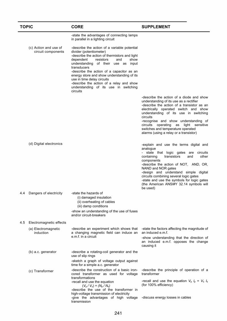
PHYSICS 0625 IGCSE 2007
11
TOPIC CORE SUPPLEMENT
(c) Action and use of
circuit components
(d) Digital electronics
-state the advantages of connecting lamps
in parallel in a lighting circuit
-describe the action of a variable potential
divider (potentiometer)
-describe the action of thermistors and light
dependent resistors and show
understanding of their use as input
transducers
-describe the action of a capacitor as an
energy store and show understanding of its
use in time delay circuits
-describe the action of a relay and show
understanding of its use in switching
circuits
-describe the action of a diode and show
understanding of its use as a rectifier
-describe the action of a transistor as an
electrically operated switch and show
understanding of its use in switching
circuits
-recognise and show understanding of
circuits operating as light sensitive
switches and temperature operated
alarms (using a relay or a transistor)
-explain and use the terms digital and
analogue
- state that logic gates are circuits
containing transistors and other
components
-describe the action of NOT, AND, OR,
NAND and NOR gates
-design and understand simple digital
circuits combining several logic gates
-state and use the symbols for logic gates
(the American ANSI#Y 32.14 symbols will
be used)
4.4 Dangers of electricity -state the hazards of
(i) damaged insulation
(ii) overheating of cables
(iii) damp conditions
-show an understanding of the use of fuses
and/or circuit-breakers
4.5 Electromagnetic effects
(a) Electromagnetic
induction
-describe an experiment which shows that
a changing magnetic field can induce an
e.m.f. in a circuit
-state the factors affecting the magnitude of
an induced e.m.f.
-show understanding that the direction of
an induced e.m.f. opposes the change
causing it
(b) a.c. generator -describe a rotating-coil generator and the
use of slip rings
-sketch a graph of voltage output against
time for a simple a.c. generator
(c) Transformer -describe the construction of a basic iron-
cored transformer as used for voltage
transformations
-recall and use the equation
(Vp / Vs) = (Np / Ns)
-describe the use of the transformer in
high-voltage transmission of electricity
-give the advantages of high voltage
transmission
-describe the principle of operation of a
transformer
-recall and use the equation Vp lp = Vs Is
(for 100% efficiency)
-discuss energy losses in cables
241

PHYSICS 0625 IGCSE 2007
12
TOPIC CORE SUPPLEMENT
(d) The magnetic effect
of a current
- describe the pattern of the magnetic field
due to currents in straight wires and in
solenoids
-describe applications of the magnetic
effect of current, including the action of a
relay
-state the qualitative variation of the
strength of the magnetic field over salient
parts of the pattern
-describe the effect on the magnetic field of
changing the magnitude and direction of
the current
(e) Force on a current-
carrying conductor
-describe an experiment to show that a
force acts on a current-carrying conductor
in a magnetic field, including the effect of
reversing:
(i) the current
(ii) the direction of the field
-describe an experiment to show the
corresponding force on beams of charged
particles
-state and use the relative directions of
force, field and current
(f) d.c. motor -state that a current-carrying coil in a
magnetic field experiences a turning effect
and that the effect is increased by
increasing the number of turns on the coil
-relate this turning effect to the action of
an electric motor
-describe the effect of increasing the
current
4.6 Cathode ray oscilloscopes
(a) Cathode rays -describe the production and detection of
cathode rays
-describe their deflection in electric fields
-state that the particles emitted in
thermionic emission are electrons
(b) Simple treatment of
cathode-ray
oscilloscope
-describe in outline the basic structure and
action of a cathode-ray oscilloscope
(detailed circuits are not required)
-use and describe the use of a cathode-ray
oscilloscope to display waveforms
5. Atomic Physics
5.1 Radioactivity
(a) Detection of
radioactivity
-show awareness of the existence of
background radiation
-describe the detection of !-particles, "-
particles and ! -rays
(b) Characteristics of the
three kinds of
emission
-state that radioactive emissions occur
randomly over space and time
-state, for radioactive emissions:
(i) their nature
(ii) their relative ionising effects
(iii) their relative penetrating abilities
-describe their deflection in electric fields
and magnetic fields
-interpret their relative ionising effects
(c) Radioactive decay -state the meaning of radioactive decay,
using equations (involving words or
symbols) to represent changes in the
composition of the nucleus when particles
are emitted
(d) Half-life -use the term half-life in simple calculations
which might involve information in tables or
decay curves
(e) Safety precautions -describe how radioactive materials are
handled, used and stored in a safe way
242
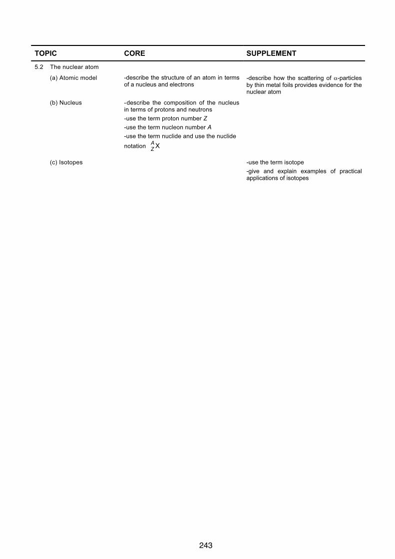
PHYSICS 0625 IGCSE 2007
13
TOPIC CORE SUPPLEMENT
5.2 The nuclear atom
(a) Atomic model -describe the structure of an atom in terms
of a nucleus and electrons
-describe how the scattering of !-particles
by thin metal foils provides evidence for the
nuclear atom
(b) Nucleus -describe the composition of the nucleus
in terms of protons and neutrons
-use the term proton number Z
-use the term nucleon number A
-use the term nuclide and use the nuclide
notation X
A
Z
(c) Isotopes -use the term isotope
-give and explain examples of practical
applications of isotopes
243