iglidur bearings for high resistance to liquid media
DESCRIPTION
This catalogue gives an overview and technical data of all the bearings that are used for high resistance to liquid media.TRANSCRIPT

320
iglidur® polymerbearings
More information www.igus.co.uk/iglidur-mediaresistance
iglidur® Specialists | High Resistance to Liquid Media
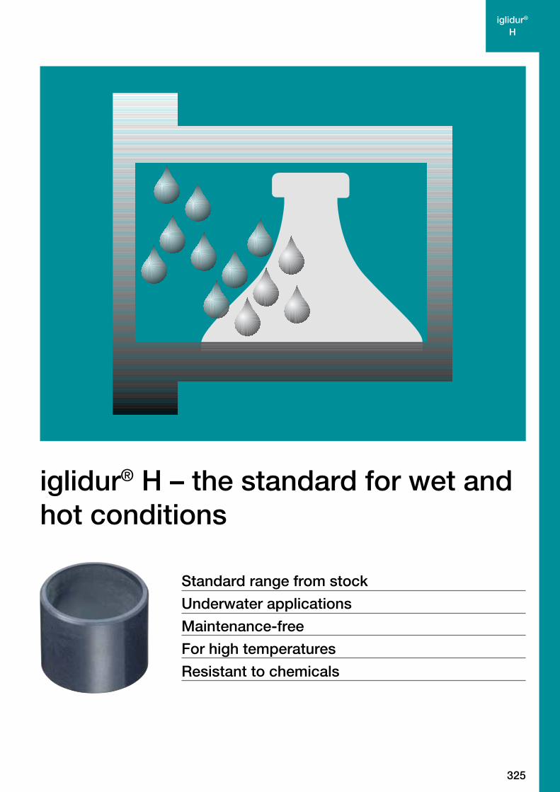
iglidur® H
the standard for wet and hot conditionsStandard range from stock from page 325
iglidur® H1
long life operationStandard range from stock from page 337
iglidur® H370
wear resistant under waterStandard range from stock from page 347
iglidur® H2
low-cost high temperature materialOn request from page 359
321
iglidur® polymerbearings
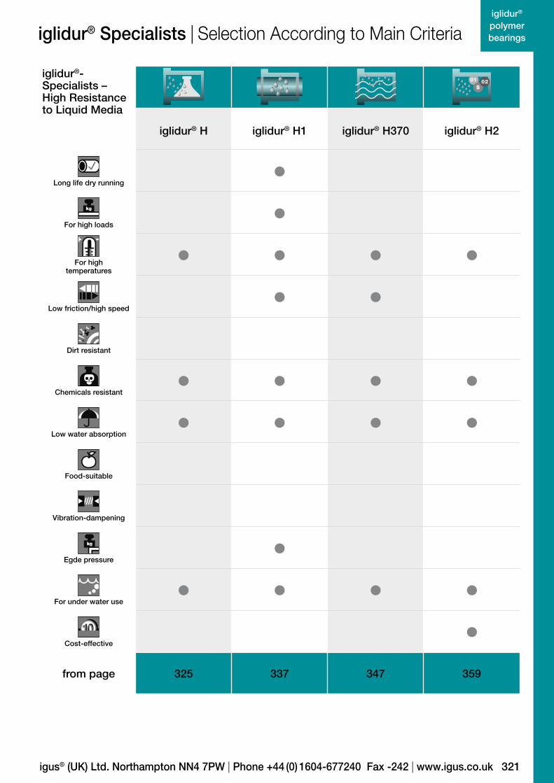
iglidur®-Specialists –High Resistance to Liquid Media
iglidur® H iglidur® H1 iglidur® H370 iglidur® H2
Long life dry running •
For high loads •
For high temperatures
• • • •
Low friction/high speed • •
Dirt resistant
Chemicals resistant • • • •
Low water absorption • • • •
Food-suitable
Vibration-dampening
Egde pressure •
For under water use • • • •
Cost-effective •from page 325 337 347 359
igus® (UK) Ltd. Northampton NN4 7PW | Phone +44 (0) 1604-677240 Fax -242 | www.igus.co.uk
iglidur® Specialists | Selection According to Main Criteria
322
iglidur® polymerbearings
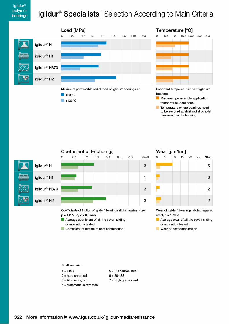
Load [MPa]0 20 40 60 80 100 120 140 160
iglidur® H
iglidur® H1
iglidur® H370
iglidur® H2
Maximum permissible radial load of iglidur® bearings at
+20 °C
+120 °C
Temperature [°C]0 50 100 150 200 250 300
Important temperatur limits of iglidur®
bearings
Maximum permissible application
temperature, continous
Temperature where bearings need to be secured against radial or axial movement in the housing
Wear [µm/km]0 5 10 15 20 25 Shaft
5
3
2
2
Wear of iglidur® bearings sliding against
steel, p = 1 MPa
Average wear of all the seven sliding
combination tested
Wear of best combination
Coefficient of Friction [µ]0 0.1 0.2 0.3 0.4 0.5 0.6 Shaft
iglidur® H 3
iglidur® H1 1
iglidur® H370 3
iglidur® H2 3
Coefficients of friction of iglidur® bearings sliding against steel,
p = 1.2 MPa, v = 0.3 m/s
Average coefficient of all the seven sliding
combinations tested
Coefficient of friction of best combination
More information www.igus.co.uk/iglidur-mediaresistance
iglidur® Specialists | Selection According to Main Criteria
Shaft material:
1 = Cf53
2 = hard chromed
3 = Aluminum, hc
4 = Automatic screw steel
5 = HR carbon steel
6 = 304 SS
7 = High grade steel

323
iglidur® polymerbearings
Material dataGeneral properties
Unitiglidur®
Higlidur®
H1iglidur® H370
iglidur® H2
Density g/cm3 1.71 1.60 1.60 1.69
Colour grey cream grey brown
Max. moisture absorption
at +23 °C/50 % r.h.% weight 0.1 0.1 < 0.1 < 0.1
Max. moisture absorption % weight 0.3 0.3 < 0.1 0.2
Coefficient of sliding friction.
dynamic against steelµ 0.07–0.2 0.06–0.20 0.07–0.17 0.07–0.3
pv value. max. (dry) MPa · m/s 1.37 0.8 0.74 0.58
Mechanical properties
Modulus of elasticity MPa 12,500 2,800 11,100 10,300
Tensile strength at +20 °C MPa 175 55 135 210
Compressive strength MPa 81 78 79 109
Max. recommended
surface pressure (+20 °C)MPa 90 80 75 110
Shore D hardness 87 77 82 88
Physical and thermal properties
Max. long term
application temperature°C +200 +200 +200 +200
Max. short term
application temperature°C +240 +240 +240 +240
Min. application
temperature °C –40 –40 –40 –40
Thermal conductivity W/m · K 0.6 0.24 0.5 0.24
Coefficient of thermal
expansion (at +23 °C)K–1 · 10–5 4 6 5 4
Electrical properties
Specific volume resistance Ωcm < 105 > 1012 < 105 > 1015
Surface resistance Ω < 102 > 1011 < 105 > 1014
Material resistance (at +20 °C)Chemical resistance iglidur ® H iglidur ® H1 iglidur ® H370 iglidur ® H2
Alcohol + + + +
Hydrocarbons + + + +
Greases, oils without additives + + + +
Fuels + + + +
Diluted acids + to 0 + to 0 + to 0 + to 0
Strong acids + to – + to – + to – + to –
Diluted alkalines + + + +
Strong alkalines + + bis – + +
Radiation resistance [Gy] to 2 · 102 2 · 102 2 · 102 2 · 102
igus® (UK) Ltd. Northampton NN4 7PW | Phone +44 (0) 1604-677240 Fax -242 | www.igus.co.uk
+ resistant 0 conditionally resistant – not resistant
iglidur® Specialists | Material Data

324
iglidur® polymerbearings
More information www.igus.co.uk/iglidur-mediaresistance
My Sketches
325
iglidur® H
Standard range from stock
Underwater applications
Maintenance-free
For high temperatures
Resistant to chemicals
iglidur® H – the standard for wet and hot conditions

326
iglidur® H
+200º
–40º
More information www.igus.co.uk/en/h
iglidur® H
The standard for wet and hot conditions. Resistant to chemicals and suitable for temperatures up to +200 °C. Very low coefficients of friction when used with hardened shafts.
Underwater applications
Maintenance-free
For high temperatures
Resistant to chemicals
Temperature Product Range
2 types Ø 3–70 mmmore dimensionson request
When to use it? Suitable for unterwater applications When high temperature resistance is necessary
For high mechanical loading For applications in contact with chemicals
When not to use it? When extremely high wear resistance under water is required
iglidur® H370, page 347 When universal resistance to chemicals is needed
iglidur® X, page 153 For the maximum pressure at higher
temperatures iglidur® X, page 153 iglidur® Z, page 299
327
iglidur® H
igus® (UK) Ltd. Northampton NN4 7PW | Phone +44 (0) 1604-677240 Fax -242 | www.igus.co.uk
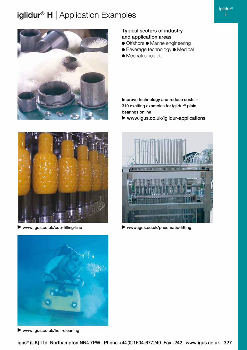
iglidur® H | Application Examples
Typical sectors of industry and application areas
Offshore Marine engineering Beverage technology Medical Mechatronics etc.
Improve technology and reduce costs –
310 exciting examples for iglidur® plain
bearings online
www.igus.co.uk/iglidur-applications
www.igus.co.uk/cup-filling-line www.igus.co.uk/pneumatic-lifting
www.igus.co.uk/hull-cleaning

328
iglidur® H
101.00.10.010.1
10
100
1.0
Lifetime calculation, CAD files and much more support www.igus.co.uk/en/h
iglidur® H | Technical Data
Graph 01: Permissible pv values for iglidur® H with a wall thickness of 1 mm dry running against a steel shaft at
+20 °C, mounted in a steel housing
Pre
ssur
e [M
Pa]
Surface speed [m/s]
Material dataGeneral properties Unit iglidur® H Testing method
Density g/cm3 1.71
Colour grey
Max. moisture absorption at +23 °C/50 % r.h. % weight 0.1 DIN 53495
Max. moisture absorption % weight 0.3
Coefficient of sliding friction, dynamic against steel µ 0.07–0.2
pv value, max. (dry) MPa · m/s 1.37
Mechanical properties
Modulus of elasticity MPa 12,500 DIN 53457
Tensile strength at +20 °C MPa 175 DIN 53452
Compressive strength MPa 81
Max. recommended surface pressure (+20 °C) MPa 90
Shore D hardness 87 DIN 53505
Physical and thermal properties
Max. long term application temperature °C +200
Max. short term application temperature °C +240
Min. application temperature °C –40
Thermal conductivity W/m · K 0.6 ASTM C 177
Coefficient of thermal expansion (at +23 °C) K–1 · 10–5 4 DIN 53752
Electrical properties1)
Specific volume resistance Ωcm < 105 DIN IEC 93
Surface resistance Ω < 102 DIN 534821) The good conductivity of this plastic material under certain circumstances can favour the generation of corrosion on the metallic contact component.
Table 01: Material data

329
iglidur® H
1.0
1.5
2.0
2.5
3.0
3.5
0.00 25 50 75 100
0.5
20 50 80 150 2000
20
40
60
80
160
120
140
100
120
Pressure [MPa] +23 °C +60 °C
iglidur® H | Technical Data
igus® (UK) Ltd. Northampton NN4 7PW | Phone +44 (0) 1604-677240 Fax -242 | www.igus.co.uk
Mechanical PropertiesThe recommended maximum surface pressure is a
mechanical material parameter. No conclusions regarding
the tribological properties can be drawn from this. With
increasing temperatures, the compressive strength of
iglidur® H plain bearings decreases. The Graph 02 shows
this inverse relationship. However, at the longterm maximum
temperature of +200° C the permissible surface pressure
is almost 25 MPa.
Permissible Surface SpeedsThe maximum permitted surface speed is dependent on
whether the temperature in the bearing location rises or not.
Running dry, iglidur® H can be used at a maximum surface
speed of 1 m/s (rotating) and 4 m/s (linear) respectively.
Linear movements enable higher surface speeds, as a large
area of the shaft contributes to the cooling.
Surface Speed, page 45
m/s Rotating Oscillating Linear
Continuous 1 0.7 3
Short term 1.5 1.1 4
Table 02: Maximum running speed
Temperaturesiglidur® H is an extremely temperature resistant material.
With a maximum permissible short term temperature of
+240 °C iglidur® H plain bearings may be used in heat
treated applications at low loads.
With increasing temperatures, the compressive strength
of iglidur® H plain bearings decreases. Graph 02 shows
this relationship.
The ambient temperatures prevalent in the bearing system
also have an effect on the bearing wear.
Application Temperatures, page 46
iglidur® H Application temperature
Minimum – 40 °C
Max. long term + 200 °C
Max. short term + 240 °C
Add. securing is required from + 120 °C
Table 03: Temperature limits
iglidur® H is a fibre-reinforced thermoplastic material
especially developed for applications in high atmospheric
humidity or under water. Bearings made of iglidur® H can
be used completely free of lubrication; in wet applications,
the surrounding media acts as additional lubricant.
Graph 03 shows the elastic deformation of iglidur® H during
radial loading. At the recommended maximum surface
pressure of 90 MPa the deformation is less than 2.5 %.
Surface Pressure, page 43
Graph 02: Recommended maximum surface pressure
as a function of temperature (90 MPa at +20 °C)
Graph 03: Deformation under pressure and temperature
Pre
ssur
e [M
Pa]
Temperature [°C]
Def
orm
atio
n [%
]

330
iglidur® H
0.00
0.10
0.20
0.30
0.40
0.50
0.1 0.7 1.0 1.3 1.6
0.15
0.25
0.35
0.45
0.05
0.4
0.1
0.2
0.3
0.4
0.05 0.10 0.15 0.20 0.25 0.30 0.400.35
0.00
0.05
0.10
0.15
0.20
100 20 30 40 50 60 8070
4
8
12
14
0
10
2
6
Lifetime calculation, CAD files and much more support www.igus.co.uk/en/h
iglidur® H | Technical Data
Shaft roughness Ra [µm]
Co
effic
ient
of
fric
tion
[µ]
Graph 06: Coefficient of friction as function of the shaft
surface (Cf53 hardened and ground steel)
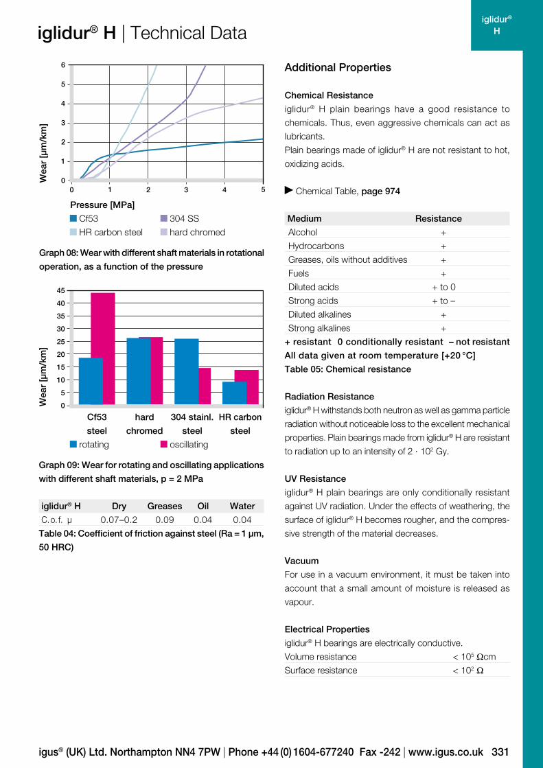
Shaft Materials
Graphs 07 to 09 show the test results of iglidur® H bearings
running against various shaft materials.
The iglidur® H bearings give different results when used in
rotating and pivoting applications. The CF53 and St37 shafts
give the best wear values in rotary applications, whereas
the V2A shafts (which are not so good for rotation) give the
best results in oscillating applications Hard chromed shafts
only give an advantage at low pressures when used with
iglidur® H bearings.
Shaft Materials, page 51
Friction and WearBoth the wear rate and the coefficient of friction values
change depending on the pressure. Interestingly, the friction
coefficient µ lowers slightly with the increase of surface
speed at constant load (see Graphs 04 and 05).
The choice of the shaft material to run against iglidur® H
bearings is critical, as this has a large impact on the wear
and friction values. More than Ra = 0.1 µm shaft surface
finish raises the coefficient of friction. For applications with
high loads, we recommend hardened and ground surfaces
with an average surface finish of Ra = 0.3 to 0.4 µm.
Coefficients of Friction and Surfaces, page 48
Wear Resistance, page 49
Graph 04: Coefficient of friction as a function of the
running speed, p = 0.75 MPa
Graph 07: Wear, rotating with different shaft materials,
pressure p = 1 MPa, v = 0.3 m/s
Graph 05: Coefficient of friction as a function of the
pressure, v = 0.01 m/s
Co
effic
ient
of
fric
tion
[µ]
Co
effic
ient
of
fric
tion
[µ]
Surface speed [m/s]
Wea
r [µ
m/k
m]
Aut
om
atic
scr
ew s
teel
HR
car
bo
n st
eel
H. a
. alu
min
um
Cf5
3, h
ard
chr
om
ed
Hig
h g
rad
e st
eel
304
SS
Cf5
3
Pressure [MPa]
331
iglidur® H
0
1
2
3
4
5
6
543210
0
5
10
15
20
25
30
35
40
45
Cf53
steel
hard
chromed
304 stainl.
steel
HR carbon
steel
rotating oscillating
iglidur® H | Technical Data
igus® (UK) Ltd. Northampton NN4 7PW | Phone +44 (0) 1604-677240 Fax -242 | www.igus.co.uk
Graph 08: Wear with different shaft materials in rotational
operation, as a function of the pressure
Wea
r [µ
m/k
m]
Pressure [MPa]
Wea
r [µ
m/k
m]
Graph 09: Wear for rotating and oscillating applications
with different shaft materials, p = 2 MPa
iglidur® H Dry Greases Oil Water
C. o. f. µ 0.07–0.2 0.09 0.04 0.04
Table 04: Coefficient of friction against steel (Ra = 1 µm,
50 HRC)
Additional Properties
Chemical Resistance
iglidur® H plain bearings have a good resistance to
chemicals. Thus, even aggressive chemicals can act as
lubricants.
Plain bearings made of iglidur® H are not resistant to hot,
oxidizing acids.
Chemical Table, page 974
Medium Resistance
Alcohol +
Hydrocarbons +
Greases, oils without additives +
Fuels +
Diluted acids + to 0
Strong acids + to –
Diluted alkalines +
Strong alkalines +
+ resistant 0 conditionally resistant – not resistant
All data given at room temperature [+20 °C]
Table 05: Chemical resistance
Radiation Resistance
iglidur® H withstands both neutron as well as gamma particle
radiation without noticeable loss to the excellent mechanical
properties. Plain bearings made from iglidur® H are resistant
to radiation up to an intensity of 2 · 102 Gy.
UV Resistance
iglidur® H plain bearings are only conditionally resistant
against UV radiation. Under the effects of weathering, the
surface of iglidur® H becomes rougher, and the compres-
sive strength of the material decreases.
Vacuum
For use in a vacuum environment, it must be taken into
account that a small amount of moisture is released as
vapour.
Electrical Properties
iglidur® H bearings are electrically conductive.
Volume resistance < 105 Ωcm
Surface resistance < 102 Ω
Cf53 304 SS
HR carbon steel hard chromed
332
iglidur® H
0.00
0.05
0.10
0.15
0.20
0.00 0.05 0.10 0.20 0.300.15 0.25
Lifetime calculation, CAD files and much more support www.igus.co.uk/en/h
iglidur® H | Technical DataR
educ
tion
of
the
inne
r-Ø
[%]
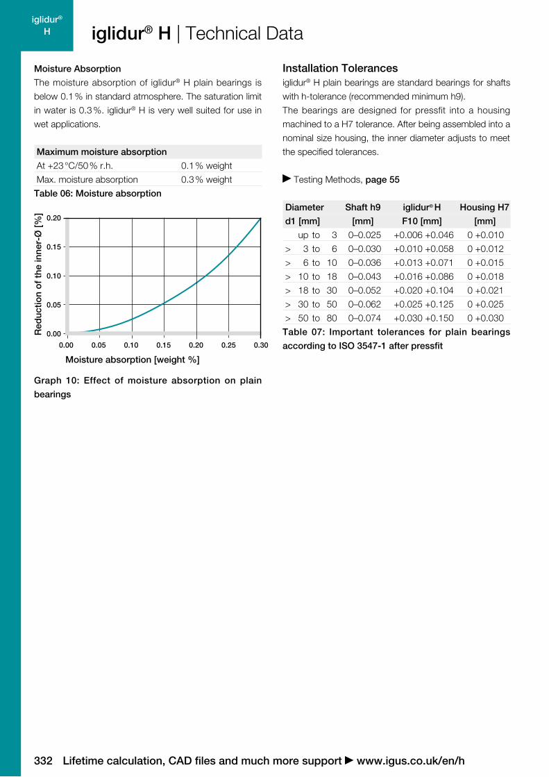
Moisture absorption [weight %]
Graph 10: Effect of moisture absorption on plain
bearings
Moisture Absorption
The moisture absorption of iglidur® H plain bearings is
below 0.1 % in standard atmosphere. The saturation limit
in water is 0.3 %. iglidur® H is very well suited for use in
wet applications.
Maximum moisture absorption
At +23 °C/50 % r.h. 0.1 % weight
Max. moisture absorption 0.3 % weight
Table 06: Moisture absorption
Installation Tolerancesiglidur® H plain bearings are standard bearings for shafts
with h-tolerance (recommended minimum h9).
The bearings are designed for pressfit into a housing
machined to a H7 tolerance. After being assembled into a
nominal size housing, the inner diameter adjusts to meet
the specified tolerances.
Testing Methods, page 55
Diameter Shaft h9 iglidur® H Housing H7
d1 [mm] [mm] F10 [mm] [mm]
up to 3 0–0.025 +0.006 +0.046 0 +0.010
> 3 to 6 0–0.030 +0.010 +0.058 0 +0.012
> 6 to 10 0–0.036 +0.013 +0.071 0 +0.015
> 10 to 18 0–0.043 +0.016 +0.086 0 +0.018
> 18 to 30 0–0.052 +0.020 +0.104 0 +0.021
> 30 to 50 0–0.062 +0.025 +0.125 0 +0.025
> 50 to 80 0–0.074 +0.030 +0.150 0 +0.030
Table 07: Important tolerances for plain bearings
according to ISO 3547-1 after pressfit
333
iglidur® H
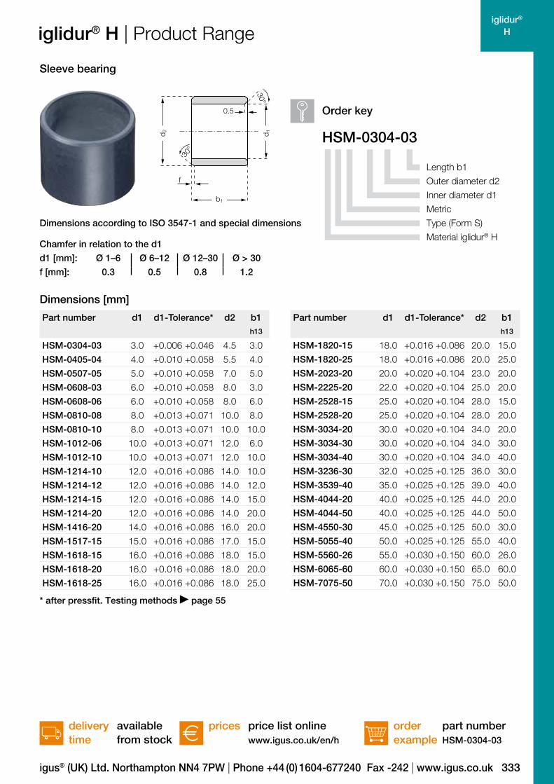
HSM-0304-03
d1 [mm]: Ø 1–6 Ø 6–12 Ø 12–30 Ø > 30
f [mm]: 0.3 0.5 0.8 1.2
30°
30°
d 1
b1
d 2
f
0.5
Part number d1 d1-Tolerance* d2 b1h13
HSM-0304-03 3.0 +0.006 +0.046 4.5 3.0
HSM-0405-04 4.0 +0.010 +0.058 5.5 4.0
HSM-0507-05 5.0 +0.010 +0.058 7.0 5.0
HSM-0608-03 6.0 +0.010 +0.058 8.0 3.0
HSM-0608-06 6.0 +0.010 +0.058 8.0 6.0
HSM-0810-08 8.0 +0.013 +0.071 10.0 8.0
HSM-0810-10 8.0 +0.013 +0.071 10.0 10.0
HSM-1012-06 10.0 +0.013 +0.071 12.0 6.0
HSM-1012-10 10.0 +0.013 +0.071 12.0 10.0
HSM-1214-10 12.0 +0.016 +0.086 14.0 10.0
HSM-1214-12 12.0 +0.016 +0.086 14.0 12.0
HSM-1214-15 12.0 +0.016 +0.086 14.0 15.0
HSM-1214-20 12.0 +0.016 +0.086 14.0 20.0
HSM-1416-20 14.0 +0.016 +0.086 16.0 20.0
HSM-1517-15 15.0 +0.016 +0.086 17.0 15.0
HSM-1618-15 16.0 +0.016 +0.086 18.0 15.0
HSM-1618-20 16.0 +0.016 +0.086 18.0 20.0
HSM-1618-25 16.0 +0.016 +0.086 18.0 25.0
Part number d1 d1-Tolerance* d2 b1h13
HSM-1820-15 18.0 +0.016 +0.086 20.0 15.0
HSM-1820-25 18.0 +0.016 +0.086 20.0 25.0
HSM-2023-20 20.0 +0.020 +0.104 23.0 20.0
HSM-2225-20 22.0 +0.020 +0.104 25.0 20.0
HSM-2528-15 25.0 +0.020 +0.104 28.0 15.0
HSM-2528-20 25.0 +0.020 +0.104 28.0 20.0
HSM-3034-20 30.0 +0.020 +0.104 34.0 20.0
HSM-3034-30 30.0 +0.020 +0.104 34.0 30.0
HSM-3034-40 30.0 +0.020 +0.104 34.0 40.0
HSM-3236-30 32.0 +0.025 +0.125 36.0 30.0
HSM-3539-40 35.0 +0.025 +0.125 39.0 40.0
HSM-4044-20 40.0 +0.025 +0.125 44.0 20.0
HSM-4044-50 40.0 +0.025 +0.125 44.0 50.0
HSM-4550-30 45.0 +0.025 +0.125 50.0 30.0
HSM-5055-40 50.0 +0.025 +0.125 55.0 40.0
HSM-5560-26 55.0 +0.030 +0.150 60.0 26.0
HSM-6065-60 60.0 +0.030 +0.150 65.0 60.0
HSM-7075-50 70.0 +0.030 +0.150 75.0 50.0
igus® (UK) Ltd. Northampton NN4 7PW | Phone +44 (0) 1604-677240 Fax -242 | www.igus.co.uk
iglidur® H | Product Range
orderexample
price list onlinewww.igus.co.uk/en/h
delivery time
prices available from stock
part numberHSM-0304-03
Length b1
Outer diameter d2
Inner diameter d1
Metric
Type (Form S)
Material iglidur® H
Order key
Sleeve bearing
Dimensions according to ISO 3547-1 and special dimensions
Chamfer in relation to the d1
Dimensions [mm]
* after pressfit. Testing methods page 55

334
iglidur® H
HFM-0405-04
d1 [mm]: Ø 1–6 Ø 6–12 Ø 12–30 Ø > 30
f [mm]: 0.3 0.5 0.8 1.2
30°
d 3d 1
b1
d 2
f b2r
r = max.
0.5 mm
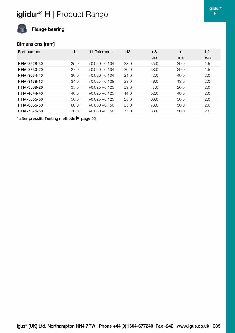
Part number d1 d1-Tolerance* d2 d3 b1 b2d13 h13 –0,14
HFM-0405-04 4.0 +0.010 +0.058 5.5 9.5 4.0 0.75
HFM-0507-05 5.0 +0.010 +0.058 7.0 11.0 5.0 1.0
HFM-0507-08 5.0 +0.010 +0.058 7.0 11.0 8.0 1.0
HFM-0608-04 6.0 +0.010 +0.058 8.0 12.0 4.0 1.0
HFM-0608-06 6.0 +0.010 +0.058 8.0 12.0 6.0 1.0
HFM-0810-07 8.0 +0.013 +0.071 10.0 15.0 7.0 1.0
HFM-0810-10 8.0 +0.013 +0.071 10.0 15.0 10.0 1.0
HFM-0810-15 8.0 +0.013 +0.071 10.0 15.0 15.0 1.0
HFM-1012-04 10.0 +0.013 +0.071 12.0 18.0 4.0 1.0
HFM-1012-09 10.0 +0.013 +0.071 12.0 18.0 9.0 1.0
HFM-1012-15 10.0 +0.013 +0.071 12.0 18.0 15.0 1.0
HFM-1012-20 10.0 +0.013 +0.071 12.0 18.0 20.0 1.0
HFM-1214-07 12.0 +0.016 +0.086 14.0 20.0 7.0 1.0
HFM-1214-10 12.0 +0.016 +0.086 14.0 20.0 10.0 1.0
HFM-1214-15 12.0 +0.016 +0.086 14.0 20.0 15.0 1.0
HFM-1416-12 14.0 +0.016 +0.086 16.0 22.0 12.0 1.0
HFM-1517-17 15.0 +0.016 +0.086 17.0 23.0 17.0 1.0
HFM-1618-17 16.0 +0.016 +0.086 18.0 24.0 17.0 1.0
HFM-1820-17 18.0 +0.016 +0.086 20.0 26.0 17.0 1.0
HFM-2023-16 20.0 +0.020 +0.104 23.0 30.0 16.5 1.5
HFM-2023-30 20.0 +0.020 +0.104 23.0 30.0 30.0 1.5
Lifetime calculation, CAD files and much more support www.igus.co.uk/en/h
iglidur® H | Product Range
orderexample
price list onlinewww.igus.co.uk/en/h
delivery time
prices available from stock
part numberHFM-0405-04
Length b1
Outer diameter d2
Inner diameter d1
Metric
Type (Form F)
Material iglidur® H
Flange bearing
Order key
Dimensions according to ISO 3547-1 and special dimensions
Chamfer in relation to the d1
Dimensions [mm]
* after pressfit. Testing methods page 55
335
iglidur® H
Part number d1 d1-Tolerance* d2 d3 b1 b2d13 h13 –0,14
HFM-2528-30 25.0 +0.020 +0.104 28.0 35.0 30.0 1.5
HFM-2730-20 27.0 +0.020 +0.104 30.0 38.0 20.0 1.5
HFM-3034-40 30.0 +0.020 +0.104 34.0 42.0 40.0 2.0
HFM-3438-13 34.0 +0.025 +0.125 38.0 46.0 13.0 2.0
HFM-3539-26 35.0 +0.025 +0.125 39.0 47.0 26.0 2.0
HFM-4044-40 40.0 +0.025 +0.125 44.0 52.0 40.0 2.0
HFM-5055-50 50.0 +0.025 +0.125 55.0 63.0 50.0 2.0
HFM-6065-50 60.0 +0.030 +0.150 65.0 73.0 50.0 2.0
HFM-7075-50 70.0 +0.030 +0.150 75.0 83.0 50.0 2.0
igus® (UK) Ltd. Northampton NN4 7PW | Phone +44 (0) 1604-677240 Fax -242 | www.igus.co.uk
iglidur® H | Product Range
Flange bearing
Dimensions [mm]
* after pressfit. Testing methods page 55

336
iglidur® H
Lifetime calculation, CAD files and much more support www.igus.co.uk/en/h
My Sketches

337
iglidur®
H1
Standard range from stock
High wear resistance in extreme ambient conditions
Very low coefficient of friction
High resistance to temperature and chemicals
For underbonnet applications
iglidur® H1 – long life operation

338
iglidur®
H1
+200º
–40º
More information www.igus.co.uk/en/h1
iglidur® H1
Long life operation. iglidur® H1 is the first choice when high holding times are required in extreme environmental conditions. Extreme wear resistance is coupled with excellent resistance to temperature and chemicals – not only in the packaging and foodstuff industries or the automotive industry.
High wear resistance in extreme
ambient conditions
Very low coefficient of friction
High resistance to temperature and chemicals
For underbonnet applications
Temperature Product range
2 types Ø 6–20 mmmore dimensions on request
When to use it? When extreme service life is required under the influence of temperature and humidity
When low coefficients of friction at high temperature are important
When regular aggressive cleaning is required (splashes, steam blasting)
When the bearings are used in the engine compartment
When not to use it? Wenn hohe Flächenpressungen auftreten
iglidur® Z, page 299 When the best universal chemical resistance is required
iglidur® X, page 153 When a cost-efficient high temperature bearing is sought, not the ideal wear resistance
iglidur® H2, page 359 When an FDA-compliant plain bearing with high temperature resistance is required
iglidur® A500, page 407

339
iglidur®
H1
igus® (UK) Ltd. Northampton NN4 7PW | Phone +44 (0) 1604-677240 Fax -242 | www.igus.co.uk
iglidur® H1 | Application Examples
Typical sectors of industry and application areas
Beverage technology Automation Packaging Textile technology Optical industry etc.
Improve technology and reduce costs –
310 exciting examples for iglidur® plain
bearings online
www.igus.co.uk/iglidur-applications
www.igus.co.uk/washing-chain www.igus.co.uk/form-fill-seal

340
iglidur®
H1
101.00.10.010.1
10
100
1.0
Lifetime calculation, CAD files and much more support www.igus.co.uk/en/h1
iglidur® H1 | Technical Data
Graph 01: Permissible pv values for iglidur® H1 with a wall thickness of 1 mm dry running against a steel shaft at
+20 °C, mounted in a steel housing
Pre
ssur
e [M
Pa]
Surface speed [m/s]
Material dataGeneral properties Unit iglidur® H1 Testing method
Density g/cm3 1.53
Colour cream
Max. moisture absorption at +23 °C/50 % r.h. % weight 0.1 DIN 53495
Max. moisture absorption % weight 0.3
Coefficient of sliding friction, dynamic against steel µ 0.06–0.20
pv value, max. (dry) MPa · m/s 0.8
Mechanical properties
Modulus of elasticity MPa 2,800 DIN 53457
Tensile strength at +20 °C MPa 55 DIN 53452
Compressive strength MPa 78
Max. recommended surface pressure (+20 °C) MPa 80
Shore D hardness 77 DIN 53505
Physical and thermal properties
Max. long term application temperature °C +200
Max. short term application temperature °C +240
Min. application temperature °C –40
Thermal conductivity W/m · K 0.24 ASTM C 177
Coefficient of thermal expansion (at +23 °C) K–1 · 10–5 6 DIN 53752
Electrical properties
Specific volume resistance Ωcm > 1012 DIN IEC 93
Surface resistance Ω > 1011 DIN 53482
Table 01: Material data
341
iglidur®
H1
1
2
3
4
5
6
7
00 20 40 60 80
20 50 80 120 2000
20
40
50
60
80
70
30
10
150
Pressure [MPa] +23 °C +60 °C
igus® (UK) Ltd. Northampton NN4 7PW | Phone +44 (0) 1604-677240 Fax -242 | www.igus.co.uk
iglidur® H1 | Technical Data
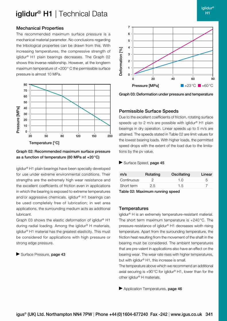
Mechanical PropertiesThe recommended maximum surface pressure is a
mechanical material parameter. No conclusions regarding
the tribological properties can be drawn from this. With
increasing temperatures, the compressive strength of
iglidur® H1 plain bearings decreases. The Graph 02
shows this inverse relationship. However, at the longterm
maximum temperature of +200 ° C the permissible surface
pressure is almost 10 MPa.
Permissible Surface SpeedsDue to the excellent coefficients of friction, rotating surface
speeds up to 2 m/s are possible with iglidur® H1 plain
bearings in dry operation. Linear speeds up to 5 m/s are
attained. The speeds stated in Table 02 are limit values for
the lowest bearing loads. With higher loads, the permitted
speed drops with the extent of the load due to the limita-
tions by the pv value.
Surface Speed, page 45
m/s Rotating Oscillating Linear
Continuous 2 1.0 5
Short term 2.5 1.5 7
Table 02: Maximum running speed
Temperaturesiglidur® H is an extremely temperature-resistant material.
The short term maximum temperature is +240 °C. The
pressure-resistance of iglidur® H1 decreases wioth rising
temperature. Apart from the surounding temperature, the
friction heat resulting from the movement of the shaft in the
bearing must be considered. The ambient temperatures
that are pre-valent in applications also have an effect on the
bearing wear. The wear rate rises with higher temperatures,
but with iglidur® H1, this increase is small.
The temperature above which we recommend an additional
axial securing is +90 °C for iglidur® H1, lower than for the
other iglidur® H materials.
Application Temperatures, page 46
iglidur® H1 plain bearings have been specially developed
for use under extreme environmental conditions. Their
strengths are the extremely high wear resistance and
the excellent coefficients of friction even in applications
in which the bearing is exposed to extreme temperatures
and/or aggressive chemicals. iglidur® H1 bearings can
be used completely free of lubrication; in wet area
applications, the surrounding medium acts as additional
lubricant.
Graph 03 shows the elastic deformation of iglidur® H1
during radial loading. Among the iglidur® H materials,
iglidur® H1 material has the greatest elasticity. This must
be considered for applications with high pressure or
strong edge pressure.
Surface Pressure, page 43
Graph 02: Recommended maximum surface pressure
as a function of temperature (80 MPa at +20 °C)
Graph 03: Deformation under pressure and temperature
Pre
ssur
e [M
Pa]
Temperature [°C]
Def
orm
atio
n [%
]

342
iglidur®
H1
0.00
0.05
0.10
0.15
0.20
0.25
0.0 0.5 1.0 1.5 2.0
0.00
0.05
0.10
0.20
0.25
0.00 0.50 1.00 1.50 2.00
0.15
0.25 0.75 1.25 1.75
0.00
0.05
0.10
0.15
0.20
100 20 30 40 50 60 8070
Lifetime calculation, CAD files and much more support www.igus.co.uk/en/h1
iglidur® H1 | Technical Data
Shaft roughness Ra [µm]
Co
effic
ient
of
fric
tion
[µ]
Shaft Materials
Graphs 06 to 09 display a summary of the results of tests
with different shaft materials conducted with iglidur® H1
plain bearings in the igus® laboratory.
The iglidur® H1 plain bearings display excellent wear
behavior in combination with a wide variety of shaft
materials both in rotating and pivoting operations. On the
V2A shafts in particular, iglidur® H1 attains very low wear
rates both in rotating and pivoting operations. Even on
hard-coated aluminum shafts, iglidur® H1 plain bearings
attain high service life in rotating applications with low to
medium loads.
Shaft Materials, page 51
Graph 06: Coefficient of friction as function of the shaft
surface (Cf53 hardened and ground steel)
iglidur® H1 Application temperature
Minimum –40 °C
Max. long term +200 °C
Max. short term +240 °C
Add. securing is required from + 80 °C
Table 03: Temperature limits
Friction and WearThe coefficient of friction alters like the wear resistance with
increasing load and speed. At constant load the coefficient
of friction µ increases with the speed. At constant speed the
coefficient of friction lowers with increasing load, whereupon
almost constant values result from 40 MPa.
As the counter partner has a large influence on friction and
wear, the choice of the appropriate shaft can be decisive.
Smoother shafts than Ra = 0.1 µm raises the coefficient of
friction. For applications with high loads, we recommend
hardened and smoothed surfaces with an average surface
finish of Ra = 0.3 to 0.4 µm.
Coefficients of Friction and Surfaces, page 48
Wear Resistance, page 49
Graph 04: Coefficient of friction as a function of the
running speed, p = 0.75 MPa
Graph 05: Coefficient of friction as a function of the
pressure, v = 0.01 m/s
Co
effic
ient
of
fric
tion
[µ]
Co
effic
ient
of
fric
tion
[µ]
Surface speed [m/s]
Pressure [MPa]

343
iglidur®
H1
0.5
1.0
1.5
2.0
0.0
0
1
2
3
4
643210 5
0
1
3
5
7
2
4
6
Cf53 304 SS
HR carbon steel hard chromed
Cf53
steel
hard
chromed
304 stainl.
steel
HR carbon
steel
rotating oscillating
igus® (UK) Ltd. Northampton NN4 7PW | Phone +44 (0) 1604-677240 Fax -242 | www.igus.co.uk
iglidur® H1 | Technical DataW
ear
[µm
/km
]
Graph 09: Wear for rotating and oscillating applications
with different shaft materials, p = 2 MPa
Graph 08: Wear with different shaft materials in rotational
operation, as a function of the pressure
Graph 07: Wear, rotating with different shaft materials,
pressure p = 0.75 MPa, v = 0.5 m/s
H. a
. alu
min
um
Cf5
3, h
ard
chr
om
ed
304
SS
Cf5
3
Wea
r [µ
m/k
m]
Wea
r [µ
m/k
m]
Pressure [MPa]
Additional Properties
Chemical Resistance
iglidur® H1 bearings have a good resistance against
chemicals. Hence even chemicals can act as lubricants.
The iglidur® H1 plain bearings are not resistant against
hot, oxidizing acids and some other particularly aggressive
chemicals.
Chemical Table, page 974
Medium Resistance
Alcohol +
Hydrocarbons +
Greases, oils without additives +
Fuels +
Diluted acids + to 0
Strong acids + to –
Diluted alkalines +
Strong alkalines + to –
+ resistant 0 conditionally resistant – not resistant
All data given at room temperature [+20 °C]
Table 05: Chemical resistance
Radiation Resistance
Resistant to radiation up to an intensity of 2 · 102 Gy
UV Resistance
iglidur® H1 bearings are only conditionally resistant to UV
rays. The surface of iglidur® H1 becomes coarser under
the influence of atmospheric conditions and the wear
increases. Therefore the use of iglidur® H1 plain bearings
in applications directly exposed to weathering should be
tested in individual cases.
Vacuum
Water elements, even if only little, should be degassed for
use in vacuum. The use in vacuum is generally possible.
Electrical Properties
iglidur® H1 plain bearings are electrically insulating.
Volume resistance > 1012 Ωcm
Surface resistance > 1011 Ω
Hig
h g
rad
e st
eel
iglidur® H1 Dry Greases Oil Water
C. o. f. µ 0.06–0.20 0.09 0.04 0.04
Table 04: Coefficient of friction against steel (Ra = 1 µm,
50 HRC)
344
iglidur®
H1
0.00
0.05
0.10
0.15
0.20
0.00 0.05 0.10 0.20 0.300.15 0.25
Lifetime calculation, CAD files and much more support www.igus.co.uk/en/h1
iglidur® H1 | Technical DataR
educ
tion
of
the
inne
r-Ø
[%]
Moisture absorption [weight %]
Graph 10: Effect of moisture absorption on plain
bearings
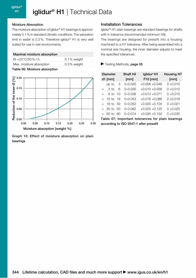
Moisture Absorption
The moisture absorption of iglidur® H1 bearings is approxi-
mately 0.1 % in standard climatic conditions. The saturation
limit in water is 0.3 %. Therefore iglidur® H1 is very well
suited for use in wet environments.
Maximal moisture absorption
At +23 °C/50 % r.h. 0.1 % weight
Max. moisture absorption 0.3 % weight
Table 06: Moisture absorption
Installation Tolerancesiglidur® H1 plain bearings are standard bearings for shafts
with h-tolerance (recommended minimum h9).
The bearings are designed for pressfit into a housing
machined to a H7 tolerance. After being assembled into a
nominal size housing, the inner diameter adjusts to meet
the specified tolerances.
Testing Methods, page 55
Diameter Shaft h9 iglidur® H1 Housing H7
d1 [mm] [mm] F10 [mm] [mm]
up to 3 0–0.025 +0.006 +0.046 0 +0.010
> 3 to 6 0–0.030 +0.010 +0.058 0 +0.012
> 6 to 10 0–0.036 +0.013 +0.071 0 +0.015
> 10 to 18 0–0.043 +0.016 +0.086 0 +0.018
> 18 to 30 0–0.052 +0.020 +0.104 0 +0.021
> 30 to 50 0–0.062 +0.025 +0.125 0 +0.025
> 50 to 80 0–0.074 +0.030 +0.150 0 +0.030
Table 07: Important tolerances for plain bearings
according to ISO 3547-1 after pressfit

345
iglidur®
H1
H1SM-0608-06
d1 [mm]: Ø 1–6 Ø 6–12 Ø 12–30 Ø > 30
f [mm]: 0.3 0.5 0.8 1.2
30°
30°
d 1
b1
d 2
f
0.5
Part number d1 d1-Tolerance* d2 b1h13
H1SM-0304-05 3.0 +0.006 +0.046 4.0 5.0
H1SM-0507-05 5.0 +0.010 +0.058 7.0 5.0
H1SM-0608-06 6.0 +0.010 +0.058 8.0 6.0
H1SM-0608-10 6.0 +0.010 +0.058 8.0 10.0
H1SM-0810-10 8.0 +0.013 +0.071 10.0 10.0
H1SM-0810-15 8.0 +0.013 +0.071 10.0 15.0
H1SM-1012-10 10.0 +0.013 +0.071 12.0 10.0
H1SM-1012-15 10.0 +0.013 +0.071 12.0 15.0
H1SM-1214-12 12.0 +0.016 +0.086 14.0 12.0
H1SM-1618-15 16.0 +0.016 +0.086 18.0 15.0
H1SM-2023-15 20.0 +0.020 +0.104 23.0 15.0
H1SM-2023-20 20.0 +0.020 +0.104 23.0 20.0
H1SM-2528-30 25.0 +0.020 +0.104 28.0 30.0
H1SM-3034-30 30.0 +0.020 +0.104 34.0 30.0
H1SM-3539-30 35.0 +0.025 +0.125 39.0 30.0
H1SM-4044-40 40.0 +0.025 +0.125 44.0 40.0
* after pressfit. Testing methods page 55
igus® (UK) Ltd. Northampton NN4 7PW | Phone +44 (0) 1604-677240 Fax -242 | www.igus.co.uk
iglidur® H1 | Product Range
orderexample
price list onlinewww.igus.co.uk/en/h1
delivery time
prices available ex stock
part numberH1SM-0608-06
Order key
Sleeve bearing
Length b1
Outer diameter d2
Inner diameter d1
Metric
Type (Form S)
Material iglidur® H1
Dimensions according to ISO 3547-1 and special dimensions
Chamfer in relation to the d1
Dimensions [mm]
346
iglidur®
H1
30°
d 3d 1
b1
d 2
f b2r
r = max.
0.5 mm
Part number d1 d1-Tolerance* d2 d3 b1 b2d13 h13 –0,14
H1FM-0304-05 3.0 +0.006 +0.046 4.0 7.5 5.0 0.75
H1FM-0507-05 5.0 +0.010 +0.058 7.0 11.0 5.0 1.0
H1FM-0608-06 6.0 +0.010 +0.058 8.0 12.0 6.0 1.0
H1FM-0810-10 8.0 +0.013 +0.071 10.0 15.0 10.0 1.0
H1FM-1012-10 10.0 +0.013 +0.071 12.0 18.0 10.0 1.0
H1FM-1214-12 12.0 +0.016 +0.086 14.0 20.0 12.0 1.0
H1FM-1214-20 12.0 +0.016 +0.086 14.0 20.0 20.0 1.0
H1FM-1618-17 16.0 +0.016 +0.086 18.0 24.0 17.0 1.0
H1FM-1618-25 16.0 +0.016 +0.086 18.0 24.0 25.0 1.0
H1FM-1820-12 18.0 +0.016 +0.086 20.0 26.0 12.0 1.0
H1FM-2023-21 20.0 +0.020 +0.104 23.0 30.0 21.0 1.5
H1FM-2023-30 20.0 +0.020 +0.104 23.0 30.0 30.0 1.5
H1FM-2528-21 25.0 +0.020 +0.104 28.0 35.0 21.0 1.5
H1FM-3034-26 30.0 +0.020 +0.104 34.0 42.0 26.0 2.0
H1FM-3539-26 35.0 +0.025 +0.125 39.0 47.0 26.0 2.0
H1FM-4044-40 40.0 +0.025 +0.125 44.0 52.0 40.0 2.0
* after pressfit. Testing methods page 55
Lifetime calculation, CAD files and much more support www.igus.co.uk/en/h1
iglidur® H1 | Product Range
orderexample
price list onlinewww.igus.co.uk/en/h1
delivery time
prices available ex stock
part numberH1FM-0608-06
H1FM-0608-06
Flange bearing
Order key
Length b1
Outer diameter d2
Inner diameter
Metric
Type (Form F)
Material iglidur® H1
d1 [mm]: Ø 1–6 Ø 6–12 Ø 12–30 Ø > 30
f [mm]: 0.3 0.5 0.8 1.2
Dimensions according to ISO 3547-1 and special dimensions
Chamfer in relation to the d1
Dimensions [mm]

347
iglidur® H370
Standard range from stock
Wear-resistant – especially under water
High temperature resistance –40 °C to +200 °C
High resistance to chemicals
iglidur® H370 – wear resistant under water

348
iglidur® H370
+200º
–40º
More information www.igus.co.uk/en/h370
iglidur® H370
Wear resistant under water. iglidur® H370 is the right solution for underwater applications. The bearings absorb extremely high loads, resist chemicals and can be used at temperatures up to +200 °C.
Wear-resistant – especially under water
High temperature resistance
–40 °C to +200 °C
High resistance to chemicals
Temperature Product Range
2 types Ø 3–75 mmmore dimensions on request
When to use it? For underwater use When it is dependent on high temperature resistance
When high mechanical loading and wear resistance is required
When good resistance to chemicals is required
When not to use it? When mechanical reaming of the wall surface is necessary
iglidur® M250, page 107 When high wear resistance in temperaturesis required
iglidur® H1, page 337 For use in dirty surroundings
iglidur® Z, page 299 When a cost-efficient, large-volume solution is required
iglidur® H2, page 359

349
iglidur® H370
igus® (UK) Ltd. Northampton NN4 7PW | Phone +44 (0) 1604-677240 Fax -242 | www.igus.co.uk
iglidur® H370 | Application Examples
Typical sectors of industry and application areas
Offshore Marine engineering Fluid technology Packaging Plant construction etc.
Improve technology and reduce costs –
310 exciting examples for iglidur® plain
bearings online
www.igus.co.uk/iglidur-applications
www.igus.co.uk/oilplatform
www.igus.co.uk/ultrasonic-tests

350
iglidur® H370
101.00.10.0010.1
10
100
1.0
0.01
Lifetime calculation, CAD files and much more support www.igus.co.uk/en/h370
iglidur® H370 | Technical Data
Graph 01: Permissible pv values for iglidur® H370 with a wall thickness of 1 mm dry running against a steel shaft
at +20 °C, mounted in a steel housing
Pre
ssur
e [M
Pa]
Surface speed [m/s]
Material dataGeneral properties Unit iglidur® H370 Testing method
Density g/cm3 1.66
Colour grey
Max. moisture absorption at +23 °C/50 % r.h. % weight 0.1 DIN 53495
Max. moisture absorption % weight 0.1
Coefficient of sliding friction, dynamic against steel µ 0.07–0.17
pv value, max. (dry) MPa · m/s 0.74
Mechanical properties
Modulus of elasticity MPa 11,100 DIN 53457
Tensile strength at +20 °C MPa 135 DIN 53452
Compressive strength MPa 79
Max. recommended surface pressure (+20 °C) MPa 75
Shore D hardness 82 DIN 53505
Physical and thermal properties
Max. long term application temperature °C +200
Max. short term application temperature °C +240
Min. application temperature °C –40
Thermal conductivity W/m · K 0.5 ASTM C 177
Coefficient of thermal expansion (at +23 °C) K–1 · 10–5 5 DIN 53752
Electrical properties
Specific volume resistance Ωcm < 105 DIN IEC 93
Surface resistance Ω < 105 DIN 53482
Table 01: Material data

351
iglidur® H370
20 50 80 120 2000
20
40
60
80
160
120
140
100
150
1
2
3
4
5
6
7
8
00 25 50 75
Pressure [MPa] +23 °C +60 °C
igus® (UK) Ltd. Northampton NN4 7PW | Phone +44 (0) 1604-677240 Fax -242 | www.igus.co.uk
iglidur® H370 | Technical Data
Mechanical PropertiesThe recommended maximum surface pressure is a
mechanical material parameter. No conclusions regarding
the tribological properties can be drawn from this. With
increasing temperatures, the compressive strength of
iglidur® H370 plain bearings decreases. The Graph 02
shows this inverse relationship. However, at the longterm
maximum temperature of +200 ° C the permissible surface
pressure is almost 10 MPa.
Permissible Surface SpeedsThe maximum permitted surface speed is dependent
on whether the temperature in the bearing location rises
strongly or not. iglidur® H370 is suitable for surface speeds
up to 1 m/s (rotating) and 3 m/s (linear) respectively.
The maximum values stated in Table 02 are valid only
with minimum pressure loads and are often not attained
in practice.
Surface Speed, page 45
m/s Rotating Oscillating Linear
Continuous 1.2 0.8 4
Short term 1.5 1.1 5
Table 02: Maximum running speed
Temperaturesiglidur® H370 is an extremely temperature-resistant mate-
rial. With a short-term permitted maximum temperature
of +240 °C, the iglidur® H370 bearings can in otherwise
unloaded condition be subjected for instance, to a paint
drying process. With increasing temperatures, the com-
pressive strength of iglidur® H370 bearings decreases. The
ambient temperatures that are pre-valent in applications
also have an effect on the bearing wear. The wear rises
with increasing temperatures.
iglidur® H370 loses about 75 % of its compressive strength
with a rise in temperature range, from room temperature
to +150 °C. In contrast the increase in wear is hardly noti-
ceable in the same temperature range.
Application Temperatures, page 46
iglidur® H370 Application temperature
Minimum –40 °C
Max. long term +200 °C
Max. short term +240 °C
Add. securing is required from +100 °C
Table 03: Temperature limits
iglidur® H370 is an advanced development of the iglidur® H
series. The material is characterized by particularly low
water absorption and clearly enhanced wear resistance.
With regard to the mechanical and thermal characteristic
values, iglidur® H370 shows the same features as iglidur® H.
Graph 02 shows how iglidur® H370 elastically deforms
under radial load. Under the maximum recommended sur-
face pressure of 75 MPa, the deformation at room tempe-
rature amounts to about 2.5 %.
Surface Pressure, page 43
Graph 02: Recommended maximum surface pressure
as a function of temperature (75 MPa at +20 °C)
Graph 03: Deformation under pressure and temperature
Pre
ssur
e [M
Pa]
Temperature [°C]
Def
orm
atio
n [%
]

352
iglidur® H370
0.1
0.2
0.3
0.4
0.05 0.10 0.15 0.20 0.25 0.30 0.35
0.00
0.05
0.10
0.15
0.20
0.25
150 30 45 60 75
1.0
2.0
3.0
4.0
5.0
0.0
1.5
2.5
3.5
4.5
0.5
0.10
0.20
0.30
0.40
0.1 0.7 1.3 1.6 1.9
0.15
0.25
0.35
1.00.4
Lifetime calculation, CAD files and much more support www.igus.co.uk/en/h370
iglidur® H370 | Technical Data
Shaft roughness Ra [µm]
Co
effic
ient
of
fric
tion
[µ]
Graph 06: Coefficient of friction as function of the shaft
surface (Cf53 hardened and ground steel)Graph 04: Coefficient of friction as a function of the
running speed, p = 0.75 MPa
Graph 07: Wear, rotating with different shaft materials,
pressure, p = 1 MPa, v = 0,3 m/s
Graph 05: Coefficient of friction as a function of the
pressure, v = 0.01 m/s
Co
effic
ient
of
fric
tion
[µ]
Co
effic
ient
of
fric
tion
[µ]
Surface speed [m/s]
Pressure [MPa]
Wea
r [µ
m/k
m]
Friction and WearThe coefficients of friction and wear in iglidur® H370 are
more favorable than in iglidur® H. There is no better material
than iglidur® H370 especially for underwater applications.
The coefficient of friction alters only little, like the wear resi-
stance with increasing load and surface speed. This con-
nection illustrates the excellent suitability of iglidur® H370
bearings with high loads.
Friction and wear also depend to a high degree on the
reverse partner. Very smooth shafts increase the coefficient
of both friction and wear. The ideally suited is a smoothed
surface with an average surface finish of Ra = 0.2 to 0.4 µm.
Coefficients of Friction and Surfaces, page 48
Wear Resistance, page 49
Aut
om
atic
scr
ew s
teel
HR
car
bo
n st
eel
H. a
. alu
min
um
Cf5
3, h
ard
chr
om
ed
Hig
h g
rad
e st
eel
304
SS
Cf5
3
Shaft Materials
Graphs 06 to 09 show the test results of iglidur® H370
bearings running against various shaft materials.
For loads up to 2 MPa, the hard-chromed shaft is the best
counter partner for the iglidur® H370 bearings in rotating
applications. The high coefficients of wear with V2A shafts
are striking, which due to their extremely smooth surfaces
are prone to the stick-slip effect. The St37 shaft shows
better values than Cf53, despite same values in the lowest
range, from 2 MPa.
On the other hand, the V2A shaft shows a clear advantage
in pivoting movements. (Graph 08).
Shaft Materials, page 51

353
iglidur® H370
353
0.0
4.5
6.0
7.5
9.0
10.5
12.0
543210
1.5
3.0
0.0
2.5
5.0
7.5
10.0
12.5
15.0
17.5
20.0
22.5
Cf53
steel
hard
chromed
304 stainl.
steel
HR carbon
steel
rotating oscillating
igus® (UK) Ltd. Northampton NN4 7PW | Phone +44 (0) 1604-677240 Fax -242 | www.igus.co.uk
iglidur® H370 | Technical DataW
ear
[µm
/km
]
Graph 09: Wear for rotating and oscillating applications
with different shaft materials, p = 2 MPa
iglidur® H370 Dry Greases Oil Water
C. o. f. µ 0.07–0.17 0.09 0.04 0.04
Table 04: Coefficient of friction against steel (Ra = 1 µm,
50 HRC)
Graph 08: Wear with different shaft materials in rotational
operation, as a function of the pressure
Wea
r [µ
m/k
m]
Pressure [MPa]
Additional Properties
Chemical Resistance
iglidur® H370 bearings have a good resistance against
chemicals. They are resistant to most lubricants.
The iglidur® is not affected by most weak organic and
inorganic acids.
Chemical Table, page 974
Medium Resistance
Alcohol +
Hydrocarbons +
Greases, oils without additives +
Fuels –
Diluted acids –
Strong acids –
Diluted alkalines + to 0
Strong alkalines + to 0
+ resistant 0 conditionally resistant – not resistant
All data given at room temperature [+20 °C]
Table 05: Chemical resistance
Radiation Resistance
iglidur® H370 withstands neutron and gamma particle
radiation without detectable losses of its excellent mechanical
properties. Plain bearings made from iglidur® H370 are
resistant to radiation up to an intensity of 2 · 102 Gy.
UV Resistance
iglidur® H370 plain bearings are permanently resistant
against UV radiation.
Vacuum
In a vacuum environment, moisture is released as a vapour.
Due to its low moisture absorption, use in a vacuum is
possible.
Electrical Properties
iglidur® H370 plain bearings are electrically conductive.
Volume resistance < 105 Ωcm
Surface resistance < 105 Ω
Cf53 304 SS
HR carbon steel hard chromed
354
iglidur® H370
0.00
0.02
0.04
0.06
0.08
0.10
0.00 0.02 0.04 0.06 0.100.08
Lifetime calculation, CAD files and much more support www.igus.co.uk/en/h370
iglidur® H370 | Technical DataR
educ
tion
of
the
inne
r-Ø
[%]
Moisture absorption [weight %]
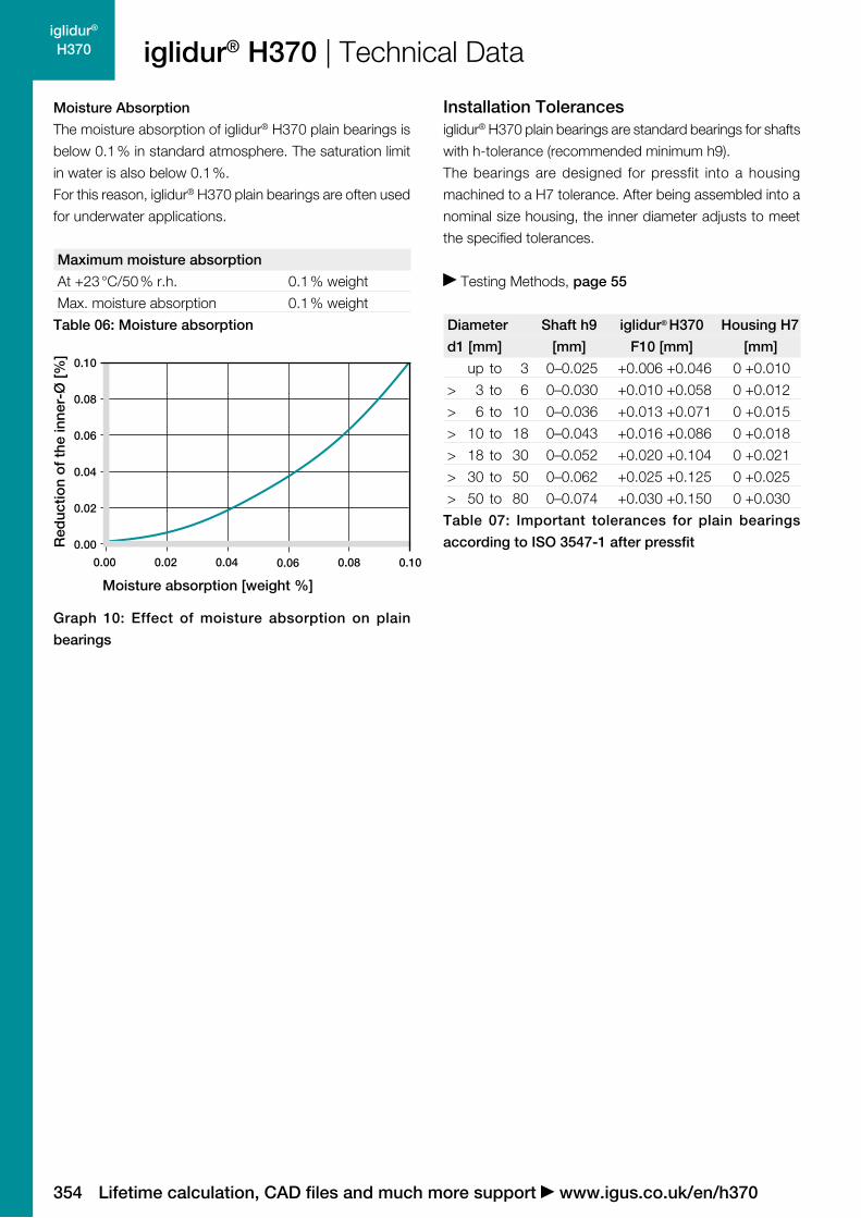
Moisture Absorption
The moisture absorption of iglidur® H370 plain bearings is
below 0.1 % in standard atmosphere. The saturation limit
in water is also below 0.1 %.
For this reason, iglidur® H370 plain bearings are often used
for underwater applications.
Maximum moisture absorption
At +23 °C/50 % r.h. 0.1 % weight
Max. moisture absorption 0.1 % weight
Table 06: Moisture absorption
Graph 10: Effect of moisture absorption on plain
bearings
Installation Tolerancesiglidur® H370 plain bearings are standard bearings for shafts
with h-tolerance (recommended minimum h9).
The bearings are designed for pressfit into a housing
machined to a H7 tolerance. After being assembled into a
nominal size housing, the inner diameter adjusts to meet
the specified tolerances.
Testing Methods, page 55
Diameter Shaft h9 iglidur® H370 Housing H7
d1 [mm] [mm] F10 [mm] [mm]
up to 3 0–0.025 +0.006 +0.046 0 +0.010
> 3 to 6 0–0.030 +0.010 +0.058 0 +0.012
> 6 to 10 0–0.036 +0.013 +0.071 0 +0.015
> 10 to 18 0–0.043 +0.016 +0.086 0 +0.018
> 18 to 30 0–0.052 +0.020 +0.104 0 +0.021
> 30 to 50 0–0.062 +0.025 +0.125 0 +0.025
> 50 to 80 0–0.074 +0.030 +0.150 0 +0.030
Table 07: Important tolerances for plain bearings
according to ISO 3547-1 after pressfit

355
iglidur® H370
price list onlinewww.igus.co.uk/en/h370
prices
H370SM-0304-03
d1 [mm]: Ø 1–6 Ø 6–12 Ø 12–30 Ø > 30
f [mm]: 0.3 0.5 0.8 1.2
30°
30°
d 1
b1
d 2
f
0.5
Part number d1 d1-Tolerance* d2 b1h13
H370SM-0304-03 3.0 +0.006 +0.046 4.5 3.0
H370SM-0405-04 4.0 +0.010 +0.058 5.5 4.0
H370SM-0405-12 4.0 +0.010 +0.058 5.5 12.0
H370SM-0507-05 5.0 +0.010 +0.058 7.0 5.0
H370SM-0608-06 6.0 +0.010 +0.058 8.0 6.0
H370SM-0810-08 8.0 +0.013 +0.071 10.0 8.0
H370SM-1012-10 10.0 +0.013 +0.071 12.0 10.0
H370SM-1214-10 12.0 +0.016 +0.086 14.0 10.0
H370SM-1214-15 12.0 +0.016 +0.086 14.0 15.0
H370SM-1517-15 15.0 +0.016 +0.086 17.0 15.0
H370SM-1618-15 16.0 +0.016 +0.086 18.0 15.0
Part number d1 d1-Tolerance* d2 b1h13
H370SM-1618-20 16.0 +0.016 +0.086 18.0 20.0
H370SM-1820-15 18.0 +0.016 +0.086 20.0 15.0
H370SM-2023-20 20.0 +0.020 +0.104 23.0 20.0
H370SM-2528-20 25.0 +0.020 +0.104 28.0 20.0
H370SM-3034-30 30.0 +0.020 +0.104 34.0 30.0
H370SM-3539-40 35.0 +0.025 +0.125 39.0 40.0
H370SM-4044-50 40.0 +0.025 +0.125 44.0 50.0
H370SM-5055-40 50.0 +0.025 +0.125 55.0 40.0
H370SM-5560-26 55.0 +0.030 +0.150 60.0 26.0
H370SM-6065-60 60.0 +0.030 +0.150 65.0 60.0
H370SM-7580-60 75.0 +0.030 +0.150 80.0 60.0
igus® (UK) Ltd. Northampton NN4 7PW | Phone +44 (0) 1604-677240 Fax -242 | www.igus.co.uk
iglidur® H370 | Product Range
orderexample
delivery time
available from stock
part numberH370SM-0304-03
Order key
Sleeve bearing
Length b1
Outer diameter d2
Inner diameter d1
Metric
Type (Form S)
Material iglidur® H370
Dimensions according to ISO 3547-1 and special dimensions
Chamfer in relation to the d1
Dimensions [mm]
Part number d1 d2 b1 d1* Housing Bore Shaft Sizeh13 max. min. max. min. max. min.
H370SI-0203-03 1/8 3/16 3/16 .1269 .1251 .1878 .1873 .1243 .1236
H370SI-0304-04 3/16 1/4 1/4 .1892 .1873 .2503 .2497 .1865 .1858
H370SI-0405-04 1/4 5/16 1/4 .2521 .2498 .3128 .3122 .2490 .2481
H370SI-0506-06 5/16 3/8 3/8 .3148 .3125 .3753 .3747 .3115 .3106
H370SI-0607-08 3/8 15/32 1/2 .3773 .3750 .4691 .4684 .3740 .3731
H370SI-0809-08 1/2 19/32 1/2 .5030 .5003 .5941 .5934 .4990 .4980
H370SI-1011-12 5/8 23/32 3/4 .6280 .6253 .7192 .7184 .6240 .6230
H370SI-1214-12 3/4 7/8 3/4 .7541 .7505 .8755 .8747 .7491 .7479
H370SI-1416-16 7/8 1 1 .8791 .8757 1.0005 .9997 .8741 .8729
H370SI-1618-16 1 1 1/8 1 1.0041 1.0007 1.1255 1.1247 .9991 .9979
H370SI-2022-20 1 1/4 1 13/32 1 1/4 1.2548 1.2508 1.4068 1.4058 1.2488 1.2472
* after pressfit. Testing methods page 55
Dimensions [Inch]

356
iglidur® H370
30°
d 3d 1
b1
d 2
f b2r
r = max.
0.5 mm
Part Number d1 d1-Tolerance* d2 d3 b1 b2d13 h13 –0,14
H370FM-0405-04 4.0 +0.010 +0.058 5.5 9.5 4.0 0.75
H370FM-0507-05 5.0 +0.010 +0.058 7.0 11.0 5.0 1.0
H370FM-0608-06 6.0 +0.010 +0.058 8.0 12.0 6.0 1.0
H370FM-0810-06 8.0 +0.013 +0.071 10.0 15.0 6.0 1.0
H370FM-0810-15 8.0 +0.013 +0.071 10.0 15.0 15.0 1.0
H370FM-1012-10 10.0 +0.013 +0.071 12.0 18.0 10.0 1.0
H370FM-1012-20 10.0 +0.013 +0.071 12.0 18.0 20.0 1.0
H370FM-1012-145 10.0 +0.013 +0.071 12.0 18.0 14.5 1.0
H370FM-1214-07 12.0 +0.016 +0.086 14.0 20.0 7.0 1.0
H370FM-1214-12 12.0 +0.016 +0.086 14.0 20.0 12.0 1.0
H370FM-1214-15 12.0 +0.016 +0.086 14.0 20.0 15.0 1.0
H370FM-1416-12 14.0 +0.016 +0.086 16.0 22.0 12.0 1.0
H370FM-1517-17 15.0 +0.016 +0.086 17.0 23.0 17.0 1.0
H370FM-1618-10 16.0 +0.016 +0.086 18.0 24.0 10.0 1.0
H370FM-1618-17 16.0 +0.016 +0.086 18.0 24.0 17.0 1.0
H370FM-1820-12 18.0 +0.016 +0.086 20.0 26.0 12.0 1.0
H370FM-1820-17 18.0 +0.016 +0.086 20.0 26.0 17.0 1.0
H370FM-2023-16 20.0 +0.020 +0.104 23.0 30.0 16.0 1.5
H370FM-2023-21 20.0 +0.020 +0.104 23.0 30.0 21.5 1.5
H370FM-2023-30 20.0 +0.020 +0.104 23.0 30.0 30.0 1.5
H370FM-222532-215 22.0 +0.020 +0.104 25.0 32.0 21.5 1.5
H370FM-2528-30 25.0 +0.020 +0.104 28.0 35.0 30.0 1.5
H370FM-3034-40 30.0 +0.020 +0.104 34.0 42.0 40.0 2.0
H370FM-3539-26 35.0 +0.025 +0.125 39.0 47.0 26.0 2.0
H370FM-4044-40 40.0 +0.025 +0.125 44.0 52.0 40.0 2.0
Lifetime calculation, CAD files and much more support www.igus.co.uk/en/h370
iglidur® H370 | Product Range
orderexample
price list onlinewww.igus.co.uk/en/h370
delivery time
prices available from stock
part numberH370FM-0405-04
H370FM-0405-04
Flange bearing
Order key
Length b1
Outer diameter d2
Inner diameter d1
Metric
Type (Form F)
Material iglidur® H370
d1 [mm]: Ø 1–6 Ø 6–12 Ø 12–30 Ø > 30
f [mm]: 0.3 0.5 0.8 1.2
Dimensions according to ISO 3547-1 and special dimensions
Chamfer in relation to the d1
Dimensions [mm]
* after pressfit. Testing methods page 55

357
iglidur® H370
Part Number d1 d1-Tolerance* d2 d3 b1 b2d13 h13 –0,14
H370FM-5055-50 50.0 +0.025 +0.125 55.0 63.0 50.0 2.0
H370FM-6065-50 60.0 +0.030 +0.150 65.0 73.0 50.0 2.0
H370FM-7075-50 70.0 +0.030 +0.150 75.0 83.0 50.0 2.0
igus® (UK) Ltd. Northampton NN4 7PW | Phone +44 (0) 1604-677240 Fax -242 | www.igus.co.uk
iglidur® H370 | Product Range
Flange bearing
Dimensions [mm]
* after pressfit. Testing methods page 55
Part number d1 d2 b1 d3 b2 d1* Housing Bore Shaft Sizeh13 –0,14 max. min. max. min. max. min.
H370FI-0203-03 1/8 3/16 3/16 .312 .032 .1269 .1251 .1878 .1873 .1243 .1236
H370FI-0304-04 3/16 1/4 1/4 .375 .032 .1892 .1873 .2503 .2497 .1865 .1858
H370FI-0405-04 1/4 5/16 1/4 .500 .032 .2521 .2498 .3128 .3122 .2490 .2481
H370FI-0506-06 5/16 3/8 3/8 .562 .032 .3148 .3125 .3753 .3747 .3115 .3106
H370FI-0607-08 3/8 15/32 1/2 .687 .046 .3773 .3750 .4691 .4684 .3740 .3731
H370FI-0809-08 1/2 19/32 1/2 .875 .046 .5030 .5003 .5941 .5934 .4990 .4980
H370FI-1011-12 5/8 23/32 3/4 1.000 .046 .6280 .6253 .7192 .7184 .6240 .6230
H370FI-1214-12 3/4 7/8 3/4 1.125 .062 .7541 .7505 .8755 .8747 .7491 .7479
H370FI-1416-16 7/8 1 1 1.250 .062 .8791 .8757 1.0005 .9997 .8741 .8729
H370FI-1618-16 1 1 1/8 1 1.375 .062 1.0041 1.0007 1.1255 1.1247 .9991 .9979
H370FI-2022-20 1 1/4 1 13/32 1 1/4 1.687 .078 1.2548 1.2508 1.4068 1.4058 1.2488 1.2472
Dimensions [Inch]
* after pressfit. Testing methods page 55

358
iglidur® H370
Lifetime calculation, CAD files and much more support www.igus.co.uk/en/h370
My Sketches

359
iglidur® H2
Can be used underwater
Cost-effective
Resistant to chemicals
For high temperatures
iglidur® H2 – low-cost high temperature material

360
iglidur® H2
More information www.igus.co.uk/en/h2360
+200º
–40º
iglidur® H2
Low-cost high temperature material. For application with high temperature requirements. Can be conditionally used in dry operation; excellent properties with additional lubrication.
For underwater use
Cost-effective
Resistant to chemicals
For high temperatures
Temperature Product range
on request
When to use it? For underwater use When a cost-effective bearing for high temperatures is desired
For applications with fuels, oils etc. Resistant to chemicals
When not to use it? When the highest wear resistance is required
iglidur® H1, page 337 iglidur® H4, page 451 iglidur® W300, page 131
When vibration dampening is necessary iglidur® B, page 485 iglidur® M250, page 107
When neither increased temperatures nor media contact occur
iglidur® GLW, page 197

361
iglidur® H2
101.00.10.0010.1
10
1,000
1.0
100
0.01
Material dataGeneral properties Unit iglidur® H2 Testing method
Density g/cm3 1.69
Colour brown
Max. moisture absorption at +23 °C/50 % r.h. % weight 0.1 DIN 53495
Max. moisture absorption % weight 0.2
Coefficient of sliding friction, dynamic against steel µ 0.07–0.3
pv value, max. (dry) MPa · m/s 0.58
Mechanical properties
Modulus of elasticity MPa 10,300 DIN 53457
Tensile strength at +20 °C MPa 210 DIN 53452
Compressive strength MPa 109
Max. recommended surface pressure (+20 °C) MPa 110
Shore D hardness 88 DIN 53505
Physical and thermal properties
Max. long term application temperature °C +200
Max. short term application temperature °C +240
Min. application temperature °C –40
Thermal conductivity W/m · K 0.24 ASTM C 177
Coefficient of thermal expansion (at +23 °C) K–1 · 10–5 4 DIN 53752
Electrical properties
Specific volume resistance Ωcm > 1015 DIN IEC 93
Surface resistance Ω > 1014 DIN 53482
Table 01: Material data
igus® (UK) Ltd. Northampton NN4 7PW | Phone +44 (0) 01604-677240 Fax -242 | www.igus.co.uk
iglidur® H2 | Technical Data
Graph 01: Permissible pv values for iglidur® H2 with a wall thickness of 1 mm dry running against a steel shaft at
+20 °C, mounted in a steel housing
Pre
ssur
e [M
Pa]
Surface speed [m/s]

362
iglidur® H2
1
2
3
4
5
6
00 30 60 90 11010 40 7020 50 80 100
20 50 80 120 2000
20
40
60
80
160
120
140
100
150
Pressure [MPa] +23 °C +60 °C
Lifetime calculation, CAD files and much more support www.igus.co.uk/en/h2
iglidur® H2 | Technical Data
Mechanical PropertiesThe recommended maximum surface pressure is a
mechanical material parameter. No conclusions regarding
the tribological properties can be drawn from this. With
increasing temperatures, the compressive strength of
iglidur® H2 plain bearings decreases. The Graph 02
shows this inverse relationship. However, at the longterm
maximum temperature of +200 °C the permissible surface
pressure is almost 20 MPa.
Permissible Surface SpeedsIn the development of iglidur® H2, cost aspects and
mechanical stability were in focus. The permitted surface
speeds of this bearing are rather low, which primarily permits
an application with slow movements or in intermittent
service.
Surface Speed, page 45
m/s Rotating Oscillating Linear
Continuous 0.9 0.6 2.5
Short term 1 0.7 3
Table 02: Maximum running speed
Temperaturesiglidur® H2 is an extremely temperature-resistant material.
The short-term permitted maximum temperature is +240 °C
and this enables the iglidur® H2 bearings to be subjected,
for instance to a paint drying process without further load.
With increasing temperatures, the compressive strength
of iglidur® H2 bearings however decreases more strongly
than in iglidur® H.
The temperatures prevailing in the bearing system also
have an influence on the bearing wear. The wear rises with
increasing temperatures.
Application Temperatures, page 46
In applications with the iglidur® H2 bearings, economical
aspects are in focus. It is the first time that it is possible
to offer such a high-performance bearing for large volume
applications with these technical advantages at such a
low price: Temperatures up to +200 °C, permitted surface
pressure till 110 N/mm2, and excellent chemical resistance.
A mixture of solid lubricants lowers the coefficient of friction
and supports the wear resistance. The iglidur® H2 bearings
are self-lubricating and suitable for all motions.
Graph 03 shows the elastic deformation of iglidur® H2
during radial loading. At the recommended maximum
surface pressure of 110 MPa the deformation is less than
3 %. The values for tensile and compressive strength are
higher than those of iglidur® H at room temperature.
Surface Pressure, page 43
Graph 02: Recommended maximum surface pressure
as a function of temperature (110 MPa at +20 °C)
Graph 03: Deformation under pressure and temperature
Pre
ssur
e [M
Pa]
Temperature [°C]
Def
orm
atio
n [%
]
363
iglidur® H2
0.25
0.30
0.35
0.1 0.4 0.7 1.0 1.61.3
0.1
0.2
0.3
0.4
0.05 0.10 0.15 0.20 0.25 0.30 0.35
0.00
0.05
0.10
0.15
0.20
0.25
0.30
100 20 30 40 50 60 8070
igus® (UK) Ltd. Northampton NN4 7PW | Phone +44 (0) 01604-677240 Fax -242 | www.igus.co.uk
iglidur® H2 | Technical Data
Shaft roughness Ra [µm]
Co
effic
ient
of
fric
tion
[µ]
Graph 06: Coefficient of friction as function of the shaft
surface (Cf53 hardened and ground steel)
iglidur® H2 Application temperature
Minimum –40 °C
Max. long term +200 °C
Max. short term +240 °C
Add. securing is required from + 110 °C
Table 03: Temperature limits
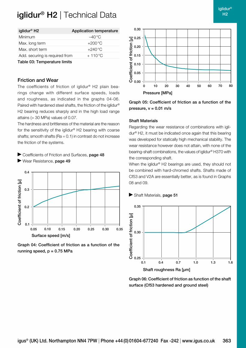
Friction and WearThe coefficients of friction of iglidur® H2 plain bea-
rings change with different surface speeds, loads
and roughness, as indicated in the graphs 04-06.
Paired with hardened steel shafts, the friction of the iglidur®
H2 bearing reduces sharply and in the high load range
attains (> 30 MPa) values of 0.07.
The hardness and brittleness of the material are the reason
for the sensitivity of the iglidur® H2 bearing with coarse
shafts; smooth shafts (Ra = 0.1) in contrast do not increase
the friction of the systems.
Coefficients of Friction and Surfaces, page 48
Wear Resistance, page 49
Shaft Materials
Regarding the wear resistance of combinations with igli-
dur® H2, it must be indicated once again that this bearing
was developed for statically high mechanical stability. The
wear resistance however does not attain, with none of the
bearing-shaft combinations, the values of iglidur® H370 with
the corresponding shaft.
When the iglidur® H2 bearings are used, they should not
be combined with hard-chromed shafts. Shafts made of
Cf53 and V2A are essentially better, as is found in Graphs
08 and 09.
Shaft Materials, page 51
Graph 04: Coefficient of friction as a function of the
running speed, p = 0.75 MPa
Graph 05: Coefficient of friction as a function of the
pressure, v = 0.01 m/s
Co
effic
ient
of
fric
tion
[µ]
Co
effic
ient
of
fric
tion
[µ]
Surface speed [m/s]
Pressure [MPa]

364
iglidur® H2
5
10
20
25
0
15
0
20
40
60
80
100
543210
0
50
100
150
75
25
125
Lifetime calculation, CAD files and much more support www.igus.co.uk/en/h2
iglidur® H2 | Technical DataW
ear
[µm
/km
]
Graph 09: Wear for rotating and oscillating applications
with different shaft materials, p = 2 MPa
Graph 08: Wear with different shaft materials in rotational
operation, as a function of the pressure
Graph 07: Wear, rotating with different shaft materials,
pressure p = 0.75 MPa, v = 0.5 m/s30
4 S
S
Hig
h g
rad
e st
eel
Wea
r [µ
m/k
m]
Wea
r [µ
m/k
m]
Pressure [MPa]
H. a
. alu
min
um
Cf5
3, h
ard
chr
om
ed
Cf5
3
iglidur® H2 Greases Fett Oil Water
C. o. f. µ 0.07–0.30 0.09 0.04 0.04
Table 04: Coefficient of friction against steel (Ra = 1 µm,
50 HRC)
Additional Properties
Chemical Resistance
iglidur® H2 bearings have a good resistance against che-
micals. They are resistant to most lubricants.
The iglidur® H2 is not affected by most weak organic and
inorganic acids.
Chemical Table, page 974
Medium Resistance
Alcohol +
Hydrocarbons +
Greases, oils without additives +
Fuels +
Diluted acids + to 0
Strong acids + to –
Diluted alkalines +
Strong alkalines +
+ resistant 0 conditionally resistant – not resistant
All data given at room temperature [+20 °C]
Table 05: Chemical resistance
Radiation Resistance
iglidur® H2 withstands neutron and gamma particle radiation
without detectable losses of its excellent mechanical
properties. Plain bearings made of iglidur® H2 are resistant
to radiation up to an intensity of 2 · 102 Gy.
UV Resistance
iglidur® H2 plain bearings change under the influence of
UV radiation and other weathering effects. The surface
becomes rougher and the compressive strength decreases.
The use of iglidur® H2 in applications that are permanently
exposed to weathering should be checked.
Vacuum
In a vacuum environment, small moisture components are
released as vapour. It is possible to use iglidur® H2 in a vacuum.
Aut
om
atic
scr
ew s
teel
HR
car
bo
n st
eel
Cf53 304 SS
HR carbon steel hard chromed
Cf53
steel
hard
chromed
304 stainl.
steel
HR carbon
steel
rotating oscillating

365
iglidur® H2
0.00
0.02
0.04
0.06
0.08
0.10
0.00 0.05 0.10 0.15 0.20
igus® (UK) Ltd. Northampton NN4 7PW | Phone +44 (0) 01604-677240 Fax -242 | www.igus.co.uk
iglidur® H2 | Technical DataR
educ
tion
of
the
inne
r-Ø
[%]
Moisture absorption [weight %]
Graph 10: Effect of moisture absorption on plain
bearings
Electrical Properties
iglidur® H2 plain bearings are electrically insulating.
Volume resistance > 1015 Ωcm
Surface resistance > 1014 Ω
Moisture Absorption
The moisture absorption of iglidur® H2 bearings is
approximately 0.1 % in standard climatic conditions. The
saturation limit in water is 0.3 %. iglidur® H2 is an ideal
material for wet environments.
Maximal Moisture Absorption
At +23 °C/50 % r.h. 0.1 % weight
Max. moisture absorption 0.2 % weight
Table 06: Moisture absorption
Installation Tolerancesiglidur® H2 plain bearings are standard bearings for shafts
with h-tolerance (recommended minimum h9). The bearings
are designed for pressfit into a housing machined to a
H7 tolerance. After being assembled into a nominal size
retainer, the inner diameter is adjusted to meet our specified
tolerances.
Testing Methods, page 55
Diameter Shaft h9 iglidur® H2 Housing H7
d1 [mm] [mm] F10 [mm] [mm]
up to 3 0–0.025 +0.006 +0.046 0 +0.010
> 3 to 6 0–0.030 +0.010 +0.058 0 +0.012
> 6 to 10 0–0.036 +0.013 +0.071 0 +0.015
> 10 to 18 0–0.043 +0.016 +0.086 0 +0.018
> 18 to 30 0–0.052 +0.020 +0.104 0 +0.021
> 30 to 50 0–0.062 +0.025 +0.125 0 +0.025
> 50 to 80 0–0.074 +0.030 +0.150 0 +0.030
Table 07: Important tolerances for plain bearings
according to ISO 3547-1 after pressfit
Product RangePlain bearings made of iglidur® H2 are manufactured to
special order. Please request iglidur® H2 bearings as an
alternative to iglidur® H and iglidur® H370 bearings in high
volume applications.