ii ad-a238 960 - defense technical information center · ii ad-a238 960, r! 'n_ ... hazardous...
TRANSCRIPT

INSTALLATION RESTORATION PROGRAM
I PRELIMINARY ASSESSMENT
* 201st RED HORSE, Civil Engineering Flight
I Fort Indiantown Gap Air National Guard StationPennsylvania Air National Guard
I Annville, Pennsylvania
I February 1991
II AD-A238 960
, R
! 'N_
HAZWRAP SUPPORT CONTRACTOR OFFICE
I Oak Ridge, Tennessee 37831Operated by MARTIN MARIETTA ENERGY SYSTEMS, INC.
For the U.S. DEPARTMENT OF ENERGY under contract DE-AC05-84OR21400
Hi ~91. ' 5

-0,
Ac- 0 S 'r----
C- U~~ ,-STATION ~-
N -2
L EG END LEEN
station Property 7 - Station Proper - ' -
Z,~ -
Copies of the final report may be purchased from:
National Technical Information Service5285 Port Royal Road
Springfield, Virginia 22161
Federal Government agencies and their contractors registered with DefenseTechnical Information Center should direct requests for copies of this report to:
Defense Technical Information CenterCameron StationAlexandria, Virginia 22304-6145

REPORT DOCUMENTATION PAGE Form Approved
Public feportmng bturden for this collecton of information, s estiratect to a~erage , cr ' pmOrse. including the time for reviewing instructions. searchingq exising data sources.gathering and maintaining the data needed, and Coffolelinq and tevnewnq the collecltcn -t 'tormition Send comments regarding this burden estmetCe or anv other a&pect of thiscollectinon of ifraioninc~~lcudingq suggetions for reducing thins burden to Wa~hrcqton -0-4guarter% Servinces, Oftectorate for innfornat'o. Oble'atons and Rtecort,. 121S ;etletfcinDavis H~gh.Iy, SWte 1204. Arhn.gton. VA 22102-4]02. and to the Office of Manage~ve-t ird -4udget. Paperworkt Reduction Project (0704-0108). Washington, 0C 20503
1. AGENCY USE ONLY (Leave blank) F 2. REPORT DATE I3. REPORT TYPE AND DATES COVEREDIFebruary 1991 Preliminary Assessment4. TITLE AND SUBTITLE Preliminary Assessment S. FUNDING NUMBERS201st RED HORSE, Civil Engineering FlightFort DIdiantown Air National Guard StationAnnville, Pennsylvania
6. AUTHOR(S)
N/A
7. PERFORMING ORGANIZATION NAME(S) AND ADDRESS(ES) B. PERFORMING ORGANIZATION
Science and Technology, Inc.REOTNMR704 South Illinois Ave.Oakridge, TN 37830
9. SPONSORING/IMONITORING AGENCY NAME(S) AND ADDRESSAES) 10. SPONSORING/ MONITORING
Hazardous Waste Remedial Actions Program AGENCY REPORT NUMBER
Oakridge, TN
Air National Guard BureauAndrews AFB. Maryland 20331 ____________
11. SUPPLEMENTARY NOTES
12a. DISTRIBUTION / AVAILABILITY STATEMENT 12lb. DISTRIBUTION CODE
Approved for public release; distribution is unlimited I13. ABSTRACT (maximum 200 words)Preliminary enVironemntal assessment for Fbrt Indiantown Gap Air National GuardStation, as part of the Installation Restoration Program. The report reflects datagathered from records reviews, interviews, and a site visit. Three sites wereidentified as potentially contaminated and recommended for further investigation.
14. SUBJECT TERMS Pennsylvania Air National Guard; Fort Indiantown 15. NUMBER OF PAGES
Gap Air National Guard Station, Annville, Pennsylvania; _________
Installation Restoration Program; Preliminary Assessment; 16. PRICE CODEWaste Holdinz Area; waste dis osal area. I__________
17. SECURITY CLASSIFICATION 18. SECURITY CLASSIFICATION 19. SECURITY CLASSIFICATION 20. LIMITATION OF ABSTRACTOF REPORT OF THIS PAGE OF ABSTRACT
UnclassifiedIIII
NSN 7540-01-280-5500 Stantdard form 298 (Rev~ 2-89)Prftcrbed by ANSI %t@ 139-nS

II
INSTALLATION RESTORATION PROGRAMPRELIMINARY ASSESSMENT
201st RED HORSE, CIVIL ENGINEERING FLIGHT271st COMBAT COMMUNICATIONS SQUADRON
211th ENGINEERING INSTALLATION SQUADRON203rd WEATHER FLIGHT
112th TACTICAL FIGHTER GROUP DOMAR201st REGIONAL EQUIPMENT OPERATORS TRAINING SCHOOL
FORT INDIANTOWN GAP AIR NATIONAL GUARD STATIONPENNSYLVANIA AIR NATIONAL GUARD
ANNVILLE, PENNSYLVANIA
Prepared for
National Guard BureauAndrews Air Force Base, Maryland 20331-6008
Prepared by
Science & Technology, Inc.704 South Illinois Avenue -.. .
Suite C-103Oak Ridge, Tennessee 37830
Contract No. DE-AC05-870R21704
Submitted to
HAZWRAP Support Contractor OfficeOak Ridge, Tennessee
Operated by Martin Marietta Energy Systems, Inc.for the Department of Energy,
Under Contract DE-AC05-84OR21400
February 1991
II
TABLE OF CONTENTS
Page
EXECUTIVE SUMMARY................................. ES-i
I. INTRODUCTION.................................... I-1A. Background.....................................1-1B. Purpose........................................1-5C. Scope..........................................1-5D. Methodology.................................... 1-6
11I. INSTALLATION DESCRIPTION.......................11-1A. Location......................... H-i3 ~B. Organization and History.................-1
III. ENVIRONMENTAL SETTING......................... III-1A. Meteorology................................... III-1B. G oo y ......... ........II-B. Gedology.................................... 111-8
1. Surface Water.............................. 111-8I 2. Groundwater.............................. 111-13D. Critical Habitats/Endangered or
Threatened Species............................. 111-14
lV. SITE EVALUATION................................LIV-1A. Activity Review................................LIV-1IB. Disposal/Spill Site Information,
Evaluation, and Hazard Assessment................. IV-1C. Other Pertinent Facts........................ .. IV-11
V. CONCLUSIONS.................................... V-1
VI. RECOMMENDATIONS.............................. VI-1
BIBLIOGRAPHY..................................... .. Bi-1
GLOSSARY OF TERMS.................................. GI-1

I
APPENDICES I
Paste IAPPENDIX A. Outside Agency Contact List .................. A-1i
APPENDIX B. USAF Hazard Assessment RatingMethodology (HARM) ... ................... B-1 i
APPENDIX C. Site Hazard Assessment RatingForms and Factor Rating Criteria ............ C-i
[IIiIIilIII
ii
IU

U
I LIST OF FIGURES
I Pag~e
Figure 1.1 Preliminary Assessment MethodologyFlow Chart ............................. 1-7
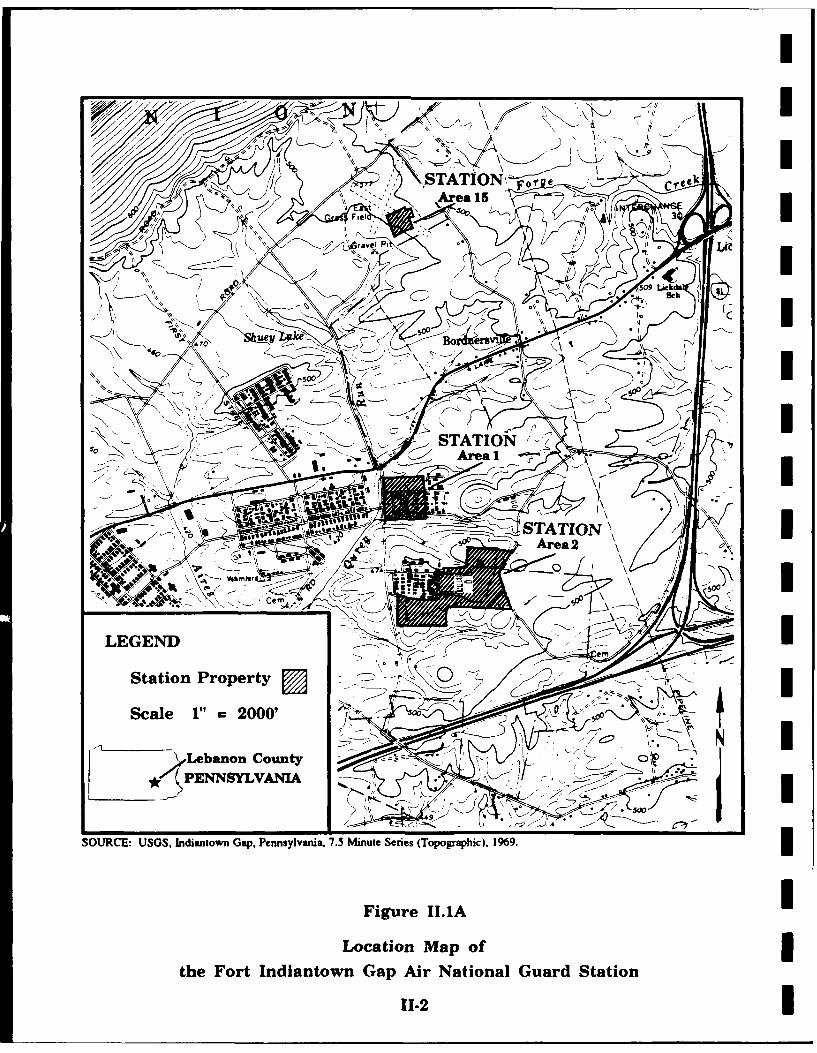
Figure II.1A Location Map of the Fort Indiantown GapAir National Guard Station ...................... 11-2
Figure II.IB Location Map of the Fort Indiantown GapAir National Guard Station ...................... 11-3
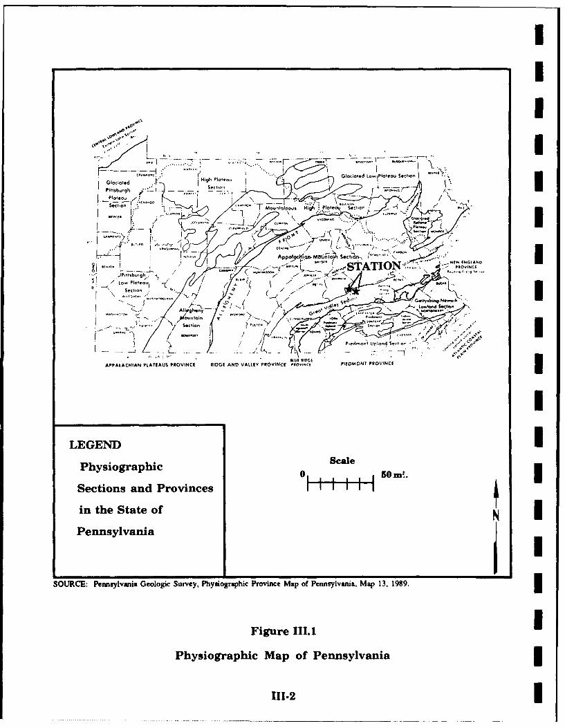
Figure 111.1 Physiographic Map of Pennsylvania ............... 111-2
Figure III.2A Generalized Stratigraphic Columnof Areas 1, 2, and 15 ...................... 111-5
I Figure III.2B Generalized Stratigraphic Columnof Area 26 ............................. 111-6
I Figure 111.3 Surficial Geologic Map of Areas 1, 2, and 15 ........ 111-7
Figure III.4 Surface Runoff Flow Route Mapfor Area Surrounding Station .................... 111-9
Figure III.5A Drainage Map of the Fort Indiantown GapAir National Guard Station - Area 1 ............. III-11
Figure I1I.5B Drainage Map of the Fort Indiantown GapAir National Guard Station - Area 2 ............. 111-12
Figure IV. 1A Potential Sites at the Fort IndiantownGap Air National Guard Station - Area 1 .......... IV-8
Figure IV. 1B Potential Sites at the Fort IndiantownGap Air National Guard Station - Area 2 .......... V-9
LIST OF TABLES
Table IV. 1 Hazardous Materials/Hazardous WastesDisposal Summary ........................ IV-2
I
I

I
ACRONYM LIST I
AGE Aerospace Ground Equipment IANG Air National GuardCCS Combat Communications SquadronCERCLA Comprehensive Environmental Response, $
Compensation, and Liability Act of 1980CES Civil Engineering SquadronCFR Code of Federal RegulationsDEQPPM Defense Environmental Quality Program Policy
MemorandumDERP Defense Environmental Restoration ProgramDoD Department of DefenseDOMAR Director of Operations, Military Air RangeDOT Department of Transportation iDRMO Defense Reutilization and Marketing OfficeEIS Engineering Installation SquadronEO Executive OrderEPA Environmental Protection AgencyFR Federal RegisterFS Feasibility StudyHARM Hazard Assessment Rating MethodologyHAS Hazard Assessment ScoreHAZWRAP Hazardous Waste Remedial Actions ProgramIRP Installation Restoration ProgramMOGAS Automotive GasolineNGB National Guard BureauOSHA Occupational Safety and Health AdministrationOWS Oil/Water SeparatorPA Preliminary AssessmentPCB Polychlorinated BiphenylsPL Public LawPOC Point of ContactPOL Petroleum, Oil, and LubricantRCRA Resource Conservation and Recovery Act of 1976R&D Research and DevelopmentREOTS Regional Equipment Operators Training SchoolRHCEF Red Horse, Civil Engineering FlightRI Remedial InvestigationSARA Superfund Amendments and Reauthorization Act of
1986SciTek Science & Technology, Inc.SI Site InvestigationTCS Tactical Control SquadronTFG Tactical Fighter GroupUSAF United States Air ForceUSC United States Code
iv iI

I
i ACRONYM LIST (continued)
USDA United States Department of AgricultureUSGS United States Geological SurveyUST Underground Storage TankWF Weather Flight
IV
IIIiIIIUIiIII
I

I EXECUTVE SUMMARY
I A. INTRODUCTION
Science & Technology, Inc. (SciTek) was retained to conduct the InstallationRestoration Program (IRP) Preliminary Assessment (PA) of the Fort IndiantownGap Air National Guard (ANG) Station [hereinafter referred to as the Station],Pennsylvania Air National Guard, located on the Fort Indiantown Gap MilitaryReservation north of Annville, Pennsylvania. For the purpose of this document,the Station shall include the total area that is used exclusively at FortIndiantown Gap.
The following six organizations occupy the Station:
o 112th Tactical Fighter Group - Director of Operations, Military Air Range(TFG DOMAR)
0 201st RED HORSE, Civil Engineering Flight (RHCEF)201st Regional Equipment Operators Training School (REOTS)
o 203rd Weather Flight (WF)o 211th Engineering Installation Squadron (EIS)o 271st Combat Communications Squadron (CCS)
The PA included the following activities:
o an on-site visit, including interviews with a total of ten persons familiarwith Station operations, and field surveys by SciTek representativesduring the week of May 29-June 1, 1990;
o acquisition and analysis of information on past hazardous materials use,waste generation, and waste disposal at the Station;
o acquisition and analysis of available geological, hydrological,meteorological, and environmental data from federal, state, and localagencies; and
I o the identification and assessment of sites on the Station that may havebeen contaminated with hazardous wastes.
K B. MAJOR FINDINGS
The organizations at the Station have used hazardous materials and generatedsmall amounts of wastes in mission-oriented operations and maintenance at theStation since 1971.
ES-1II

iI
Operations that have invol-ed the use of hazardous materials and the disposalof hazardous wastes include vehicle maintenance and aerospace groundequipment (AGE) maintenance. The hazardous wastes disposed of throughthese operations include varying quantities of petroleum oil-lubricant (POL)products, acids, paints, thinners, strippers, and solvents.
The field surveys and interviews resulted in the identification of three sitesthat exhibit the potential for contaminant presence and migration.
C. CONCLUSIONS
It has been concluded there are three sites where a potential for contaminantpresence exists.
o Site No. 1 - Compound Access Road/Parking Lot (HAS - 69)
o Site No. 2 - Waste Holding Area (HAS - 68)
o Site No. 3 - Old Waste Holding Area (HAS - 61)
D. RECOMMENDATIONS
Further work under the IRP is recommended for the identified sites todetermine the presence or absence of contamination.
IIIIII
ES.2 II

I
I. INTRODUCTION
A. Background
The Fort Indiantown Gap Air National Guard (ANG) Station [hereinafterreferred to as the Station], Pennsylvania Air National Guard, is located on theFort Indiantown Gap Military Reservation north of Annville, Pennsylvania. Sixunits presently occupy the property: 112th Tactical Fighter Group - Directorof Operations, Military Air Range (TFG DOMAR); 201st RED HORSE, CivilEngineering Flight (RHCEF); 201st Regional Equipment Operators TrainingSchool (REOTS); 203rd Weather Flight (WF); 211th Engineering InstallationSquadron (EIS); and 271st Combat Communications Squadron (CCS). Unitshave been active at the Station since 1971. Both the past and currentoperations have involved the use of potentially hazardous materia: and thedisposal of wastes. Because of the use of these materials and the disposal ofresultant wastes, the National Guard Bureau (NGB) has implemented theInstallation Restoration Program (IRP).
I The IRP is a comprehensive program designed to:
o Identify and fully evaluate suspected problems associated with pasthazardous waste disposal and/or spill sites on Department of Defense(DoD) installations and
o Control hazards to human health, welfare, and the environment that mayhave resulted from these past practices.
During June 1980, DoD issued a Defense Environmental Quality ProgramPolicy Memorandum (DEQPPM 80-6) requiring identification of past hazardouswaste disposal sites on DoD installations. The policy was issued in responseto the Resource Conservation and Recovery Act (RCRA) of 1976 and inanticipation of the Comprehensive Environmental Response, Compensation,and Liability Act (CERCLA, Public Law (PL) 96-510) of 1980, commonly knownas "Superfund." In August 1981, the President delegated certain authorityspecified under CERCLA to the Secretary of Defense via an Executive Order(EO 12316). As a result of EO 12316, DoD revised the IRP by issuingDEQPPM 81-5 (December 11, 1981), which reissued and amplified all previousdirectives and memoranda.
Although the DoD IRP and the Environmental Protection Agency (EPA)Superfund programs were essentially the same, differences in the definition ofprogram activities and lines of authority resulted in some confusion betweenDoD and state/federal regulatory agencies. These difficulties were rectified viapassage of the Superfund Amendments and Reauthorization Act (SARA, PL-99-499) of 1986. On January 23, 1987, Presidential Executive Order EO 12580
I I-1
II

I
was issued. EO 12580 effectively revoked EO 12316 and implemented the nchanges promulgated by SARA.
The most important changes effected by SARA included the following: Io Section 120 of SARA provides that federal facilities, including those in
DoD, are subject to all provisions of CERCLA/SARA concerning siteassessment, evaluation under the National Contingency Plan [40CFR300],listing on the National Priorities List, and removal/remedial actions.DoD must therefore comply with all the procedural and substantive Irequirements (guidelines, rules, regulations, and criteria) promulgated bythe EPA under Superfund authority.
o Section 211 of SARA also provides continuing statutory authority for DoDto conduct its IRP as part of the Defense Environmental RestorationProgram (DERP). This was accomplished by adding Chapter 160,Sections 2701-2707 to Title 10 United States Code (10 USC 160).
o SARA also stipulated that terminology used to describe or otherwiseidentify actions carried out under the IRP shall be substantially the Isame as the terminology of the regulations and guidelines issued by theEPA under their Superfund authority.
As a result of SARA, the operational activities of the IRP are currently defined
and described as follows: 3o Preliminary Assessment
The Preliminary Assessment (PA) process consists of personnel interviews mand a records search designed to identify and evaluate past disposaland/or spill sites that might pose a potential and/or actual hazard topublic health, public welfare, or the environment. Previously mundocumented information is obtained through the interviews. Therecords search focuses on obtaining useful information from aerialphotographs; Station plans; facility inventory documents; lists of Ihazardous materials used at the Station; Station subcontractor reports;Station correspondence; Material Safety Data Sheets; federal/state agencyscientific reports and statistics; federal administrative documents; Ifederal/state records on endangered species, threatened species, andcritical habitats; documents from local government offices; and numerousstandard reference sources.
II
1-2
II
I
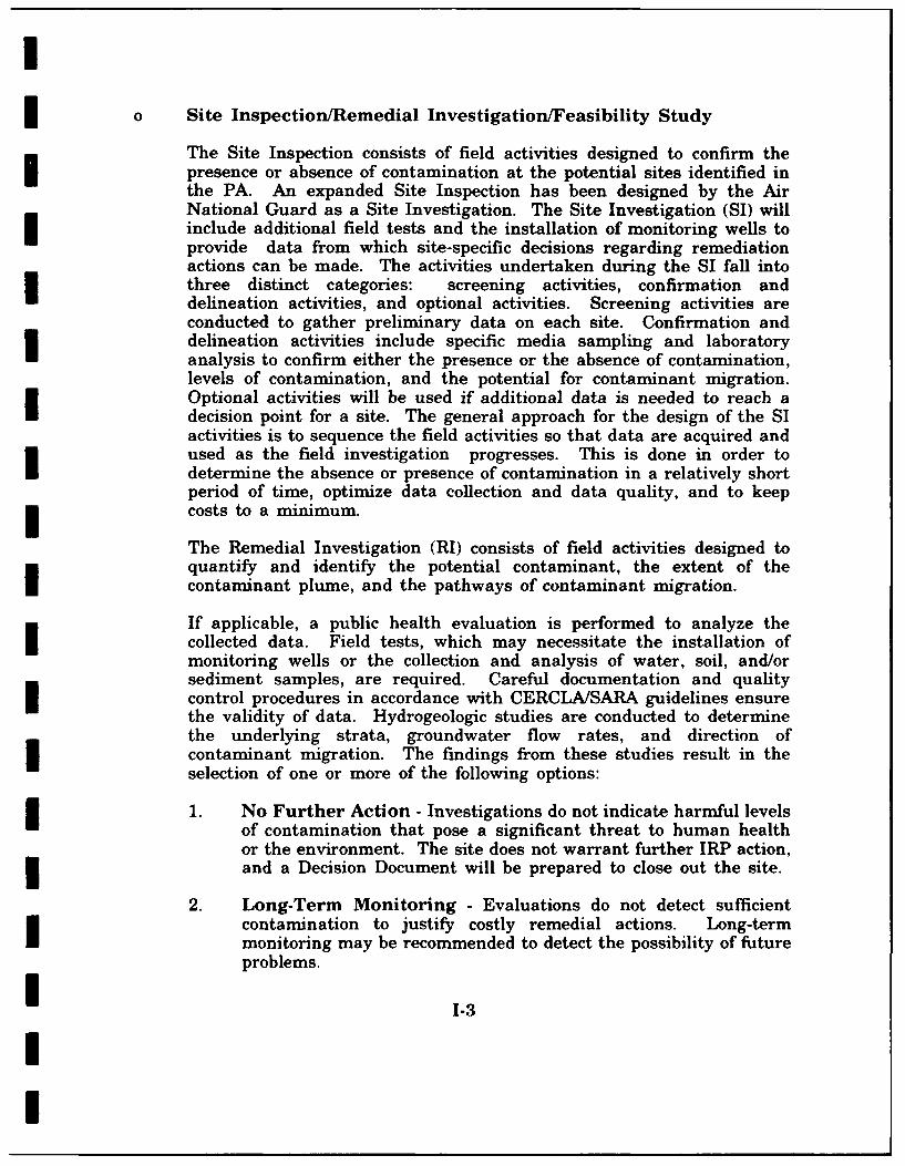
o Site Inspection/Remedial Investigation/Feasibility Study
The Site Inspection consists of field activities designed to confirm thepresence or absence of contamination at the potential sites identified inthe PA. An expanded Site Inspection has been designed by the AirNational Guard as a Site Investigation. The Site Investigation (SI) willinclude additional field tests and the installation of monitoring wells toprovide data from which site-specific decisions regarding remediationactions can be made. The activities undertaken during the SI fall intothree distinct categories: screening activities, confirmation anddelineation activities, and optional activities. Screening activities areconducted to gather preliminary data on each site. Confirmation anddelineation activities include specific media sampling and laboratoryanalysis to confirm either the presence or the absence of contamination,levels of contamination, and the potential for contaminant migration.Optional activities will be used if additional data is needed to reach adecision point for a site. The general approach for the design of the SIactivities is to sequence the field activities so that data are acquired andused as the field investigation progresses. This is done in order todetermine the absence or presence of contamination in a relatively shortperiod of time, optimize data collection and data quality, and to keep
I costs to a minimum.
The Remedial Investigation (RI) consists of field activities designed toquantify and identify the potential contaminant, the extent of thecontaminant plume, and the pathways of contaminant migration.
If applicable, a public health evaluation is performed to analyze thecollected data. Field tests, which may necessitate the installation ofmonitoring wells or the collection and analysis of water, soil, and/or
sediment samples, are required. Careful documentation and qualitycontrol procedures in accordance with CERCLA/SARA guidelines ensurethe validity of data. Hydrogeologic studies are conducted to determinethe underlying strata, groundwater flow rates, and direction ofcontaminant migration. The findings from these studies result in theselection of one or more of the following options:
1. No Further Action - Investigations do not indicate harmful levelsof contamination that pose a significant threat to human healthor the environment. The site does not warrant further IRP action,
I and a Decision Document will be prepared to close out the site.
2. Long-Term Monitoring - Evaluations do not detect sufficientcontamination to justify costly remedial actions. Long-termmonitoring may be recommended to detect the possibility of futureproblems.
I 1-3
II

mI
3. Feasibility Study - Investigation confirms the presence ofcontamination that may pose a threat to human health and/or theenvironment, and some sort of remedial action is indicated. The IFeasibility Study (FS) is therefore designed and developed toidentify and select the most appropriate remedial action. The FSmay include individual sites, groups of sites, or all sites on aninstallation. Remedial alternatives are chosen according toengineering and cost feasibility, state/federal regulatoryrequirements, public health effects, and environmental impacts.The end result of the FS is the selection of the most appropriateremedial action with concurrence by state and/or federal regulatoryagencies.
o Remedial Design/Remedial Action
The Remedial Design involves formulation and approval of theengineering designs required to implement the selected remedial action.The Remedial Action is the actual implementation of the remedialalternative. It refers to the accomplishment of measures to eliminate thehazard or, at a minimum, reduce it to an acceptable limit. Covering alandfill with an impermeable cap, pumping and treating contaminatedgroundwater, installing a new water distribution system, and in situbiodegradation of contaminated soils are examples of remedial measuresthat might be selected. In some cases, after the remedial actions havebeen completed, a long-term monitoring system may be installed as a Iprecautionary measure to detect any contaminant migration or todocument the efficiency of remediation.
o Research and Development
Research and Development (R&D) activities are not always applicable foran IRP site but may be necessary if there is a requirement for additionalresearch and development of control measures. R&D tasks may beinitiated for sites that cannot be characterized or controlled through theapplication of currently available, proven technology. It can also, insome instances, be used for sites deemed suitable for evaluating newtechnologies.
0 Immediate Action Alternatives
At any point, it may be determined that a former waste disposal site iposes an immediate threat to public health or the environment, thusnecessitating prompt removal of the contaminant. Immediate action,such as limiting access to the site, capping or removing contaminatedsoils, and/or providing an alternate water supply may suffice as effective
1-4i II

I
3 control measures. Sites requiring immediate removal action maintainIRP status in order to determine the need fbr additional remedialplanning or long-term monitoring. Removal measures or otherappropriate remedial actions may be implemented during any phase ofan IRP project.
U B. Purpose
The purpose of this IRP PA is to identify and evaluate suspected problemsassociated with past waste handling procedures, disposal sites, and spill siteson Station property.
I The potential for migration of hazardous contaminants was evaluated byvisiting the Station, reviewing existing environmental data, analyzing Stationrecords concerning the use of hazardous materials and the generation ofhazardous wastes, and conducting interviews with current Station personnelwho had knowledge of past waste disposal techniques and handling methods.Pertinent information collected and analyzed as part of the PA included arecords search of the history of the Station; the local geological, hydrological,and meteorological conditions that might influence migration of contaminants;and ecological settings that indicate environmentally sensitive conditions.
* C. Scope
The scope was limited to the identification of sites at or under primary control
of the Station and evaluation of potential receptors. The PA included:
o an on-site visit during the week of May 29-June 1, 1990;
0 acquisition of records and information on hazardous materials use andwaste handling practices;
o acquisition of available geological, hydrological, meteorological, land useand zoning, critical habitat, and related data from federal and stateagencies;
o a review and analysis of all information obtained; and
o preparation of a summary report to include recommendations for furtheraction.
1I '-5
II

I
The subcontractor effort was conducted by the following Science & Technology, iInc. (SciTek) personnel: Mr. Tracy C. Brown, Environmental Analyst;Mr. Charles T. Goodroe, Environmental Protection Specialist; and Mr. StephenB. Selecman, Geologist/Hydrogeologist. Mr. Richard Hill of the NGB is Project IOfficer for this Station and participated in the overall assessment during theweek of the station visit. Ms. Patricia Franzen of the Hazardous WasteRemedial Actions Program (HAZWRAP) and Ms. Tullete Belford of the NGBalso participated in the station visit.
The point of contact (POC) at the Station was Captain Joseph W. Mihalik(Base Civil Engineer).
D. Methodology UThe PA began with a visit to the Station to identify all operations that mayhave used hazardous materials or may have generated hazardous wastes.Figure 1.1 is a flow chart of the PA methodology.
Ten past and present Station employees familiar with the various operating iprocedures were interviewed. These interviews were conducted to determinethose areas where waste materials (hazardous or nonhazardous) were used,spilled, stored, disposed of, or released into the environment. The interviewees'knowledge and experience with Station operations averaged 15.9 years andranged from 2.5 to 32 years.
Records contained in the Station files were collected and reviewed tosupplement the information obtained from the interviews.
Detailed geological, hydrological, meteorological, and environmental data for thearea were obtained from the appropriate federal, state, and local agencies. Alisting of agency contacts is included as Appendix A.
After a detailed analysis of all the information obtained, it was concluded thatthree sites may be potentially contaminated with hazardous wastes. Under the IIRP program, when sufficient information is available, sites are numericallyscored using the Air Force Hazard Assessment Rating Methodology (HARM).A description of HARM is presented in Appendix B.
II
1-6 i
II

Ii DECISION TREE
RECORDS SEARCH & INTERVIEWS
COMPLETE LIST OF LOCATIONS ]AND POTENTIAL SITES
EVALUATION OF PAST OPERATIONSAT LISTED SITES
II
[NOPO~EN IRONMENT CON ERNST O EI
DELETE SITES VRO TO BE RATED
PROGRAMO
I
DECISION [ LHAZARDRATINGPDOCUMENT METHODOLOGY
E NUMERICALE SITE RATING
I€
CONSOLUIONSTE
DECISION SIPRILF AI OC
IFigure 1.1SPreliminary Assessment Methodology Flow Chart
i I-7

I
II. INSTALLATION DESCRIPTION
A. Location
The Station is located approximately twenty miles east of Harrisburg and justnorth of Interstate Highway 81 in the eastern portion of the Fort IndiantownGap Military Reservation. The Station consists of four parcels of land, sixorganizations, and numerous buildings. Elevation of the Station isapproximately 430 feet above mean sea level (AMSL). Figures II.1A and 1Billustrate the locations and boundaries of the four areas the Station usesexclusively.
I The Station currently occupies four separate areas for a total of 84.6 acres.Area 1 occupies 21.2 acres and houses the 201st RHCEF, 201st REOTS, andthe 203rd WF. Area 2 occupies 52.4 acres and houses the 211th EIS and the271st CCS. Within Area 26, six acres are occupied by the 112th TFG DOMAR,and within Area 15, five acres are used exclusively by the 201st REOTS. TheStation could add an additional 16.9 acres if the proposed locati ,n for theCombined Headquarters is obtained. The property contains approximately 65buildings. The major effort of construction on the Station is to maintain theexisting facilities. The population of the Station during the week numbers 105members (including sixteen students of the 201st REOTS). Unit TrainingAssembly occurs one weekend per month. The Station population during thisweekend is 585 members.
B. Organization and History
The original facilities on the Station were constructed during World War II andwere occupied by the United States Army. The property currently supports sixorganizations. Three of the units (201st, 211th, and 271st) are the principalgenerators of waste products, and the remaining three units produce onlynominal amounts. There are four vehicle maintenance and two AGEmaintenance activities at the Station.
In November 1971, the 201st RHCEF arrived at Fort Indiantown Gap andestablished the ANG Station. This is the host unit, and it controls all theroutine functions of the facility. The mission of the 201st RHCEF is to providea highly mobile, rapidly deployable civil engineering response which is self-sufficient for limited periods of time. The mission of the RHCEF was createdfrom the need by the Air Force to meet the requirements to repair damage toinstallations caused by enemy action and to provide additional troopconstruction support. The mission has not changed over the years. The 201stRHCEF has a vehicle maintenance and an AGE maintenance shop.
I II-I
II
I-I
Figur II.A0
Loation MaIothe ort ndiato GapAir atinal uardStai
1.2 Lic

UO
* ~ ~ 0 Staio1rpety:14
StLocatio Mappeof
SOUCEUSSGmte Fort Indiantown Gnnyvnap A.inuSrie aTioahc) Guad6taio
Fiur 11.B

I
The 211th EIS was originally activated as the 211th Communications IConstruction Squadron on August 26, 1953, in New York. Over the years, theunit has experienced several name changes but retained its numericaldesignation. The 211th EIS arrived at the Station in 1972. The mission of $the 211th EIS is to mobilize and deploy authorized resources and supportingassets to accomplish the engineering, installation, reconstruction, and/orreplacement of communications-computer systems and tracals. The mission has Inot changed significantly over the years. The 211th EIS has a vehiclemaintenance shop.
The 271st CCS was originally activated as the 322nd Signal Company onAugust 15, 1942, at Wendover Field, Utah. After numerous changes, itacquired its present designation as a Combat Communications Squadron onApril 1, 1976. A small detachment from the 271st CCS arrived at the Stationin 1972. In April 1974, the 271st CCS officially took up residence at theStation. The mission of the 271st CCS is to maintain, deploy, and operatetactical communications packages in support of Air Force missions worldwide.The mission has not changed significantly except for improvements inequipment. The 271st CCS has a vehicle maintenance and an AGEmaintenance shop.
The aforementioned units are the principal generators of waste materials. Thefourth unit which produces wastes (to a lesser degree) is the 112th TFGDOMAR. This unit was created in 1983 with a mission to operate andmaintain a bombing range in support of training tactical fighter aircraft of theANG, reserve, and active Air Forces. The 112th TFG DOMAR has a one-stallvehicle maintenance area at its location in Area 26. This shop has verylimited capabilities, and only minor repairs and daily services are performedat this location. Because of assigned assets, the resultant waste materials from Ioperations are very modest. The disposition of these wastes are the same asthe other units on the Station.
A need existed to tailor the training requirements for the ANG. In 1987, the201st REOTS was established to provide this specialized training within theregion. In 1989, the school expanded its charter to provide this training to all Iactive, reserve, and National Guard Civil Engineering units. The goal of theREOTS is to improve Air Force Civil Engineering's wartime capabilities byproviding pavement and equipment personnel with hands-on experience with Ikey Rapid Runway Repair equipment items. The school operates on a weeklycycle and has 16 students per class. During the week, cadre and equipmentassets are obtained from the 201st RHCEF. Equipment maintenance isperformed by the 201st RHCEF. This unit produces no hazardous wastematerial.
II11-4
II

I
In 1979, the 203rd WF arrived at the Station. The unit consists of oneindividual during the week and a total of 19 members during the trainingweekend. The mission of the 203rd WF is to provide all requested weathersupport to the ground and air forces of the 28th Infantry Division to includeobservations, forecasts, severe weather advisories, climatological information,and solar/lunar data. This unit produces no hazardous waste materials.
The units with motor vehicle and/or AGE maintenance shops are the primarygenerators of waste materials on the Station. A summary of the types of
* wastes generated can be found in Chapter IV.
The property has supported functions of the military since the 1940s. Thismay or may not have included a maintenance activity on the present Stationproperty. The repair and servicing of motor vehicles and AGE items havetaken place on the property by the assigned units over the past 19 years.There are approximately 35 underground storage tanks (USTs) for heating oil.Each vehicle maintenance area (in Area 1 and Area 2) has a refueling areaand has USTs for diesel and automotive gasoline (MOGAS) fuels. Each ofthese areas has two oil/water separators (OWSs) which aid in the preventionof water and property degradation. Reports indicate that the OWSs areinspected every six months and are cleaned as necessary. Waste products arestored in 55 gallon drums for disposal through proper channels.
Materials recognized as hazardous have been generated on this property sincethe establishment of the Station in 1971. With the awareness of hazardousmaterials and the recognition of their impact on the environment, acceptabledisposable practices and procedures have evolved. The majority of hazardouswastes are now collected and disposed of through contractors and the Defense
I Reutilization and Marketing Office (DRMO).
III 11-5
II

I
III. ENVIRONMENTAL SETTING
A. Meteorology
The following climatological data is largely derived from the National ClimaticData Center, Ashville, North Carolina, and is published in the Soil Survey ofLebanon County, Pennsylvania (United States Department of Agriculture(USDA): Soil Conservation Service, 1981). Lebanon County is characterizedby a humid continental climate. The average annual precipitation is 42.30inches and is distributed fairly evenly throughout the year with the winterreceiving slightly less than the other seasons. The amount of annualprecipitation varies within the county because of the orographic effectsproduced by the Appalachian Mountains. Annual precipitation is greatest inthe northern part of the county and generally decreases to the south. Basedon 78 years of data (1883-1961), the Station receives an average of 45 to 46inches of precipitation per year (Stuart et al, 1967). Precipitation ranges froman average monthly low of 2.47 inches in February to an average monthly highof 4.42 inches in May. By calculating net precipitation for the Stationaccording to the method outlined in the Federal Regulations CERCLA PollutionContingency Plan (United States Environmental Protection Agency, 55 FR 8813,Subpart K, March 8, 1990), a net precipitation value of approximately 14inches is obtained. The one-year, 24-hour rainfall for the area is approximately2.5 inches. Thunderstorms occur on an average of 37 days each year, mostlyin the summer. Snowfall is light to moderate and averages approximately 36inches per year. At least one inch of snow covers the ground on an averageof 50 days per year.
Winters are generally cold, and summers are mild. The average annualtemperature is about 51.6°F, and the mean summer and winter temperaturesare 76.0°F and 32.0°F, respectively. The prevailing wind direction is from thenortl'west in the winter and from the west in the summer. Wind speed ishighest in the winter at 12 mph and averages 10 mph annually.
I B. Geology
Lebanon County is located in the Appalachian Valley and Ridge and thePiedmont physiographic provinces (Figure III.1). The southern-most part of thecounty occurs in the Piedmont province while the remainder of the county islocated in the Valley and Ridge province, which is further divided into theGreat Valley and Appalachian Mountain sections. The northern extreme ofLebanon County exists in the Appalachian Mountain section while the centraltwo-thirds of the county is located in the Great Valley section. The Station issituated along Blue Mountain which represents the geographic boundarybetween the Appalachian Mountain section and the Great Valley section.Areas 1, 2, and 15 of the Station property are located south of Blue Mountain
i III-I
I
,0'-C
PII-T TF
App" I owtIo Hg Pmlole SecI. on. NJ.--' AN
~i ZLOW / TATION'._<"
Sectiono
""IAPPALACHIAN PLATEAUS PROVINCE RIDGE AND VALLEY PROVINCE fwovfNc PIEDMONT PROVINCE
LEGENDI
Physiographic Sae 50=!.
Sections and Provinces
in the State of
Pennsylvaniaj
SOURCE: Pennsylvania Geologic Survey, Phyuiographic Province Map of Pennsylvania. Map 13, 1989.
Figure 111.1
Physiographic Map of Pennsylvania
111.2I

I
I and exist in the Great Valley section. Area 26 is located on the northwestslope of Blue Mountain and occurs in the Appalachian Mountain section.
i The Appalachian Mountain section is characterized by a series of alternatingnarrow ridges and valleys that have a northeast to southwest orientation.The bedrock is chiefly composed of Middle-Paleozoic age clastics, and the moreweather resistant rocks form the ridge tops while the less resistant rockscomprise the valley floors and mountain sides. Topographic relief in theAppalachian Mountain section is high with surface elevations ranging from inexcess of 1600 feet AMSL on mountain tops to around 500 feet AMSL in thevalley floors in Lebanon County. The surface elevation at Area #26 along thenorthwest slope of Blue Mountain is approximately 1060 feet AMSL.
The Great Valley section is characterized by a broad lowland area that hasbeen moderately dissected by fluvial erosion. Bedrock largely consists of LowerPaleozoic age carbonates and shales. Primarily, Ordovician age shales andsandstones compose the bedrock in the northern part of the section whileOrdovician and Cambrian age carbonates occupy the southern one-half of theGreat Valley (Royer, 1983). Topographic relief is low to moderate with surfaceelevations ranging from 420 feet to 500 feet AMSL in the vicinity of Areas 1,2, and 15 of the Station property. The topography here gently slopes southeastfrom Blue Mountain toward Swatara Creek.
The geology of the Valley and Ridge province is complex. Regional3compressional forces from the southeast during the Late Paleozoic Era produceda network of folds and faults that are the dominant structural features of theGreat Valley and the Appalachian Mountains section. As a result of thesoutheast-oriented compressional forces, the general regional structural grainis northeast to southwest, and formations generally dip to the south (Carswellet al, 1968). The Appalachian Mountain section is dominated by open andclosed plunging folds which have planar limbs and narrow hinges. Thrust faultsand normal faults are predominant along with strike-slip faults which havebeen mapped extensively in Lebanon County (Mosley, 1954, and Bricker, 1960).The Great Valley section is characterized by thrust sheets, nappes, overturnedfolds, and steep faults (Pennsylvania Geological Survey, 1989).
The carbonate rocks found in the southern one-half of the Great Valley inLebanon County occur as part of an overturned recumbent synclinorium (Geyeret al, 1958, and Gray et al, 1958). Carbonate formations that crop out in thiscomplex become progressively younger from south to north. The northern part3 of the Great Valley in Lebanon County is composed of shales and sandstonesthat are described as lithotectonic units of the Hamburg sequence. TheHamburg sequence is complex in both depositional and structural occurrence(Royer, 1983). Kay, 1941, suggested the Hamburg sequence to beallochthonous, and many others have since supported this theory. Strose, 1946,named this sequence the Hamburg Klippe.
ii III-3
I
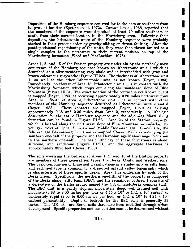
IDeposition of the Hamburg sequence occurred far to the east or southeast fromits present location (Epstein et al, 1972). Carswell et al, 1968, reported thatthe members of the sequence were deposited at least 20 miles southeast orsouth from their current location in the Harrisburg area. Following theirdeposition, the lithotectonic units of the Hamburg sequence were probablystacked in their present order by gravity sliding or thrust faulting. After thepostdepositional repositioning of the units, they were then thrust faulted as asingle complex to the northwest to their current position on top of theMartinsburg formation (Wood and MacLachlan, 1978).
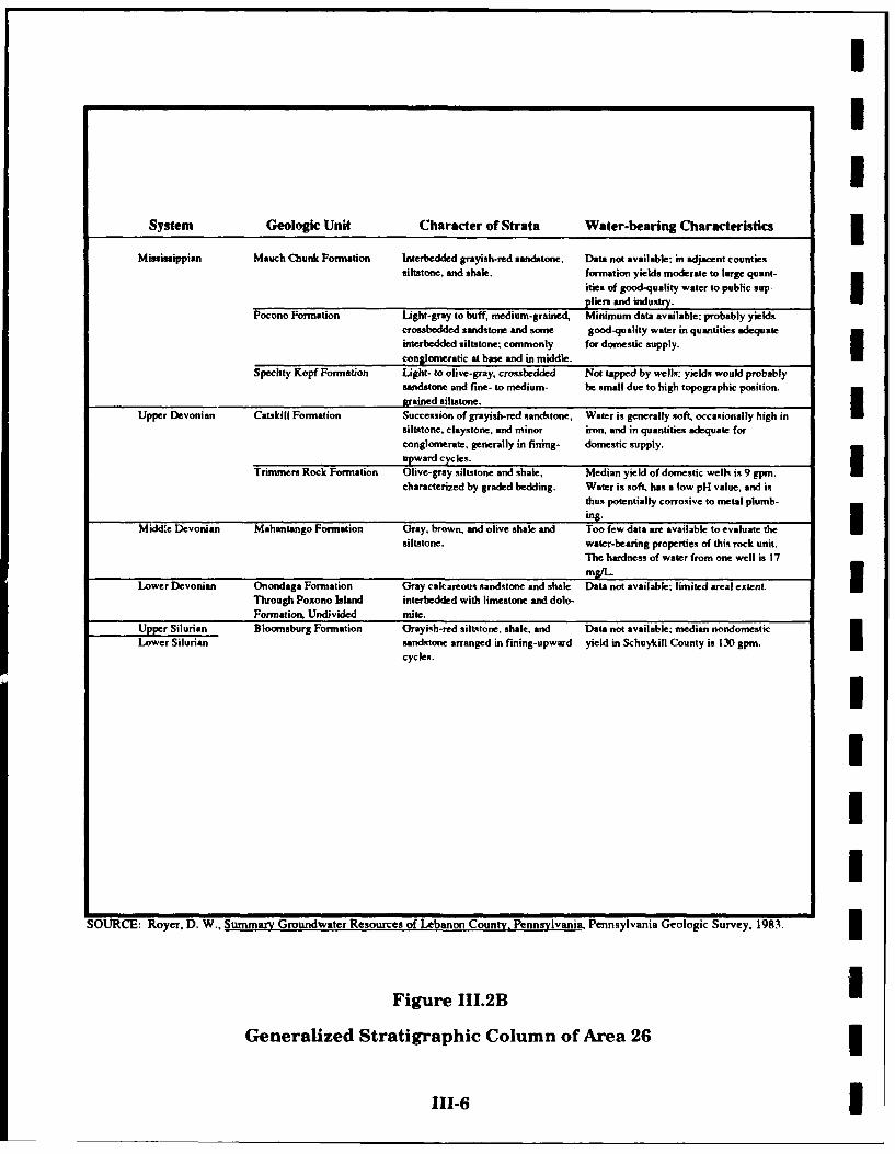
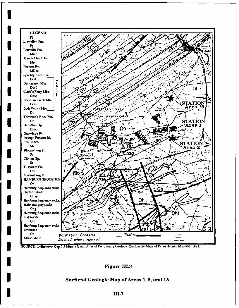
Areas 1, 2, and 15 of the Station property are underlain by the northerly mostnoccurrence of the Hamburg sequence known as lithotectonic unit 1 which isdescribed as a olive-weathering gray shale and is interbedded with gray andbrown calcareous graywacke (Figure III.2A). The thickness of lithotectonic unit1, as well as the other lithotectonic units, is not known (Royer, 1983).Immediately northwest of Area 15, lithotectonic unit 1 is in contact with theMartinsburg formation which crops out along the southeast slope of BlueMountain (Figure 111.3). The exact location of the contact is not known but itis mapped (Royer, 1983) as occurring approximately 0.20 miles northwest fromArea 15. South of Area 2, lithotectonic unit 1 is in contact with otherHImembers of the Hamburg sequence described as lithotectonic units 2 and 3(Royer, 1983). These contacts are mapped (Royer, 1983) as existingapproximately 0.65 and 0.35 miles from Area 2, respectively. A lithologic Idescription for the entire Hamburg sequence and the adjoining Martinsburgformation can be found in Figure III.2A. Area 26 of the Station property,which is located along the northwest slope of Blue Mountain, is underlain byIyounger rocks of Upper Silurian and Middle Devonian age. Specifically, theSilurian age Bloomsburg formation is mapped (Royer, 1983) as occupying thesouthern one-half of the property and the Devonian age Mahantango formationin the northern one-half. The basic lithology of these formations is shale,siltstone, and sandstone (Figure III.2B), and the aggregate thickness isapproximately 3375 feet (Royer, 1983).
The soils overlying the bedrock at Areas 1, 2, and 15 of the Station propertyare members of three general soil types: the Berks, Conly, and Weikert soils.The basic composition of these soil classifications is a shaley silty or silty loam,and each soil type is common to a dissected upland valley topography whichis characteristic of these specific areas. Area 1 is underlain by soils of theBerks group. Specifically, the northern one-fifth of the property is composedof the Berks shaley silty loam (BkC), and the remainder of Area 1 consists ofa derivative of the Berks group, named the Urban land-Berks complex (UR).The BkC unit is a gently sloping, moderately deep, well-drained soil withmoderate (0.63 to 2.00 inches per hour or 4.45 x 10⁻⁴ to 1.41 x 10' cm/sec) tomoderately rapid (2.00 to 6.00 inches per hour or 1.41 x 10' to 4.24 x 10'cm/sec) permeability. Depth to bedrock for the BkC soils is generally 33inches. The UR soils are Berks soils that have been modified through urbandevelopment. Specific properties and composition cannot be determined without
111-4
II

II
I Sequence Geologic Unit Character of Strata Water.bearing Characteristics
Hamburg Yellow Breeches Dark-gray shale with minor interbeds Median yield of domestic wells is 5 gpin.(These lithotectonic Thrust Plate of argillaceous sandstone, red shale, and Excessive concentrations of manganese areunits are in prob- limestone, a common problem. Many wells will requireable order of em- supplemental storage to meet minimum
Upper placement and water-supply needs.toCambrian( may be in reverse Lithotectonic Unit 8 Olive-weathering gray shale and brick-red Median yield of domestic wells is 15 gpm.Upper order of age.) shale with minor beds of fine-grained brown Yield of nondomestic wells is 50 gpm.
Ordovician argillaceous sandstone, quartzitic sandstoneand limestone.
Lithotectonic Unit 6 Greenish-brown siltstone and argillaceous Median yield of domestic wells is 12 gpm.sandstone and shale, with interbeds of Median nondomestic yield in Berks County
maroon shale, sandstone, limestone, is 140 gpm. Very low yields are obtainedfrom igneous and metamorphic rocks.
Lithotectonic Unit 4 Black and orange-weathering laminated Median yield of domestic wells is 15 gpm.shale, quartzite, and thin- to medium- Median nondomestic yield is 62 gpm.bedded sandy limestone.
Lithotectonic Unit 3 Interbedded red siltstone and shale, olive Median yield of domestic wells is 20 gpm.siltstone and shale, siliceous shale, and Median yield of nondomestic wells is 58
minor beds of chert and quartzitic sandstone. gpm.
Lithotectonic Unit 2 Interbedded limestone and micaceous shale Median yield of domestic wells is 15 gpm.and siltstone: massively bedded calcarenite Nondomestic yields reported for two wellsoften associated with limestone. Limestone were 400 and 500 gpm.
conglomerate and red shale are also present
minor amounts.Lithotectonic Unit I Olive-weathering gray shale and graywacke. Median yield of domestic wells is 15 gpm.
Median yield of nondomestic wells is 17.5
*__,m.
Hamburg Sequence Gray, dark-gray, and greenish gray phylittic Too few dates are available to evaluateRocks, Undifferentiated shale and silty argillite. water-bearing properties of this rock unit.
Lebanon Valley Martinsburg Formation Gray to dark-gray, buff-weathering shale. Median yield of domestic wells is 17.5 gpm.Median water hardness is 68 mg/L
Upper Hershey Formation Dark-gray argillaceous limestone. Poorly permeable aquifer. Median yield ofOrdovician domestic wells is 22 gpm. Very hard water.
Myerstown Formation Gray, crystalline, thin-bedded limestone, Too few data are available to evaluate thegraphitic at base. water-bearing properties of this rock unit.
Median yield of domestic wells in BerksCounty is 20 gpm. Very hard water.
I
SOURCE Royer, D. W., Summary Groundwater Resources of Lebanon County, Pennsylvania, Pennsylvania Geologic Survey, 1983.
1 Figure III.2A
Generalized Stratigraphic Column of Areas 1, 2, and 15
I 111-5
III
System Geologic Unit Character of Strata Water-bearing Characteristics
Mississippian Mauch Chunk Formation Interbedded grayish-red sandstone, Data no( available: in adjacent countiessiltstone, and shale, formation yields moderate to large quant-
ities of good-quality water to public suppliers and industry.
Pocono Formation Light-gray to buff, medium-grained, Minimum data available: probably yieldscrossbedded sandstone and some good-quality water in quantities adequate uinterbedded silttone; commonly for domestic supply.
conglomeratic at base and in middle.Spechty Kopf Formation Light- to alive-gray, crossbedded Not lapped by wells: yields would probably
sandstone and fie- to medium- be small due to high topographic position.g(rained siltstone.|
Upper Devonian Catskill Formation Succession of grayish-red sandstone, Water is generally soft, occasionally high insiltstonke, claygtone, and minor iron, and in quantities adequate forconglomerate, generally in fining- domestic supply. a
upward cycles.
Trimmers Rock Formation Olive-gray siltstone and shale, Median yield of domestic welh is 9 gpm.characterized by graded bedding. Water is soft, has a low pH value, and is
thus potentially corrosive to metal plumb-ing.
Middle Devonian Mahantango Formation Gray, brown, and olive shale and Too few data are available to evaluate thesiltstone. water-bearing properties of this rock unit.
The hardness of water from one well is 17mg/L.
Lower Devonian Onondaga Formation Gray calcareous sandstone and shale Data not available; limited areal extent.Through Poxono Island interbedded with limestone and dolo-
Formation, Undivided mite.
Upper Silurian Bloomsburg Formation Grayish-red silt-tone, shale, and Data not available: median nondomesticLower Silurian sandstone arranged in fining-upward yield in Schuykill County is 130 gpm.
cycles.
IIII
SOURCE Royer, D. W., Summary Groundwater Resources of Lebanon County, Pennsylvania. Pennsylvania Geologic Survey, 1983.
Figure III.2B NGeneralized Stratigraphic Column of Area 26
111-6 I
I LEGENDP1
IpPottsvile FmI AcMauch Chunk Fm
MP.....Pocono Fm.4
MDskSpechty Kopf Fm. ~
DNdDuncannon Mbr.
DccfN *OClark's Fery Mbr.
Sherman Creek Mbr.DcivSTTO
Irish Valley Mbr. Au T"N 't A P, Area 15Dtr
Trimmer's Rock Fm.T W;W
DhSTTOI Hamilton Gp. (eDsopI Onondaga Fm. ~ >
through Poxono Is!.
Sb
* Sc Fm
St
* OrnMartinsburg Fm. A v
HAMBURG SEQUENCE -
OhHabrUeunercsphyllitic shale
OhagHamburg Sequence rocks, 0h ....shale and graywacke
OhgHamburg Sequence rocks., - .I graywacke
Ohl - --- hh- Hamburg Sequence rocks,. %~-
*limeqtone __ _ _ _ __ _ _ _ __ _ _ _ _ __ _ _ _ __ _ _ _ _ __ _ _ _ __ _ _ _ _
*O Formation Contacts______ FaltsMetadiabase Dashed where inferred-
ISOURCE: Indantown Gap 7.5 Minute Quad. Atlas of Preliminary Geologic Quadrang~je Maps of Pennrylvania Mar #0 1, 198 1.
Figure 111.3
I Surficial Geologic Map of Areas 1, 2, and 15
I 111-7
i
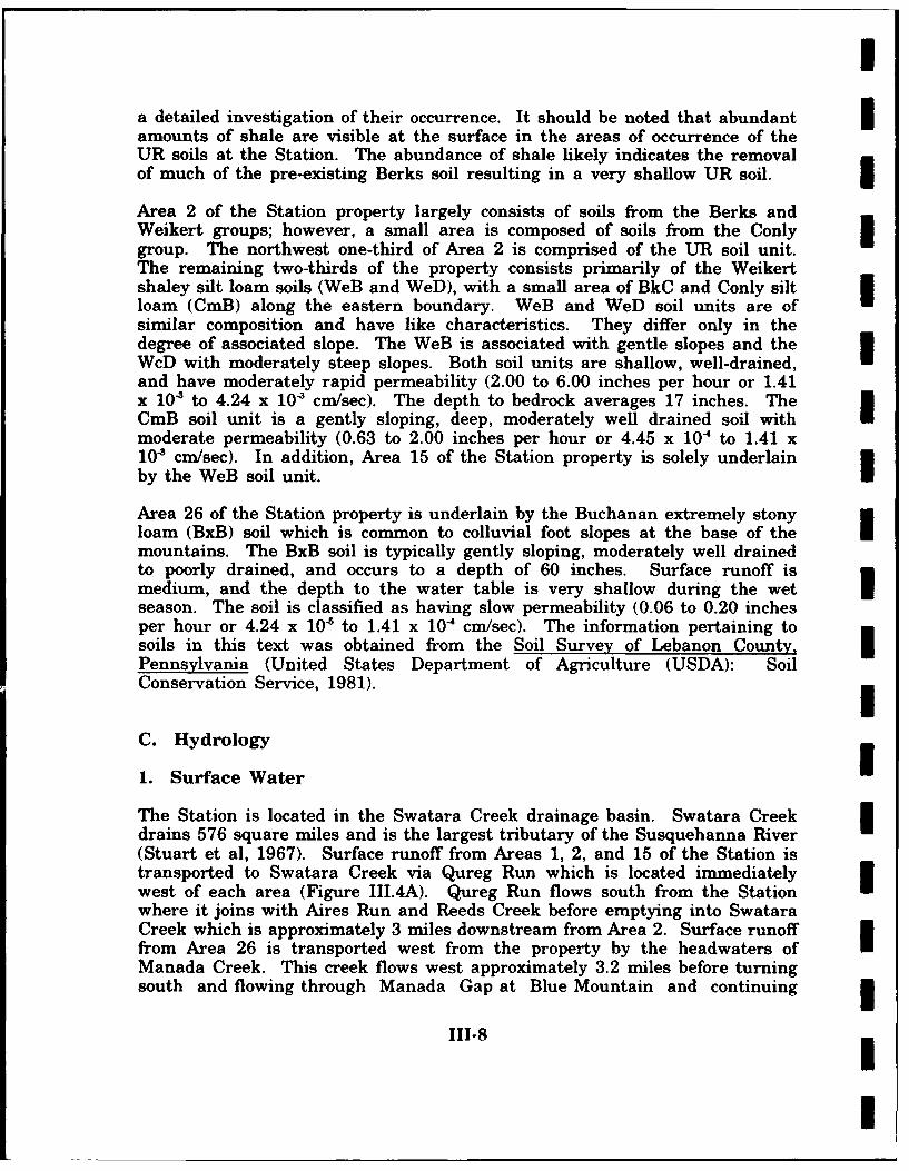
a detailed investigation of their occurrence. It should be noted that abundantamounts of shale are visible at the surface in the areas of occurrence of theUR soils at the Station. The abundance of shale likely indicates the removalof much of the pre-existing Berks soil resulting in a very shallow UR soil. iArea 2 of the Station property largely consists of soils from the Berks andWeikert groups; however, a small area is composed of soils from the Conlygroup. The northwest one-third of Area 2 is comprised of the UR soil unit.The remaining two-thirds of the property consists primarily of the Weikertshaley silt loam soils (WeB and WeD), with a small area of BkC and Conly siltloam (CmB) along the eastern boundary. WeB and WeD soil units are ofsimilar composition and have like characteristics. They differ only in thedegree of associated slope. The WeB is associated with gentle slopes and theWcD with moderately steep slopes. Both soil units are shallow, well-drained,and have moderately rapid permeability (2.00 to 6.00 inches per hour or 1.41x 10' to 4.24 x 10' cm/sec). The depth to bedrock averages 17 inches. TheCmB soil unit is a gently sloping, deep, moderately well drained soil withmoderate permeability (0.63 to 2.00 inches per hour or 4.45 x 10' to 1.41 x10' cm/sec). In addition, Area 15 of the Station property is solely underlainby the WeB soil unit.
Area 26 of the Station property is underlain by the Buchanan extremely stonyloam (BxB) soil which is common to colluvial foot slopes at the base of themountains. The BxB soil is typically gently sloping, moderately well drainedto poorly drained, and occurs to a depth of 60 inches. Surface runoff ismedium, and the depth to the water table is very shallow during the wet $season. The soil is classified as having slow permeability (0.06 to 0.20 inchesper hour or 4.24 x 10' to 1.41 x 10-' cm/sec). The information pertaining tosoils in this text was obtained from the Soil Survey of Lebanon County,Pennsylvania (United States Department of Agriculture (USDA): SoilConservation Service, 1981).
C. Hydrology
1. Surface Water
The Station is located in the Swatara Creek drainage basin. Swatara Creekdrains 576 square miles and is the largest tributary of the Susquehanna River I(Stuart et al, 1967). Surface runoff from Areas 1, 2, and 15 of the Station istransported to Swatara Creek via Qureg Run which is located immediatelywest of each area (Figure III.4A). Qureg Run flows south from the Stationwhere it joins with Aires Run and Reeds Creek before emptying into SwataraCreek which is approximately 3 miles downstream from Area 2. Surface runofffrom Area 26 is transported west from the property by the headwaters ofManada Creek. This creek flows west approximately 3.2 miles before turningsouth and flowing through Manada Gap at Blue Mountain and continuing
111-8
l

XIA11~~i / 1A5O~-
I - ,Lick,I /e
*ey50
AraI0~
Apro'Cae Loato of
-Oan
vi Figure Cre.4
Surfceae Ruloff Flw-oteMp-o-Ae-Sroud-gSato
Scl 1112000

I
approximately 8 miles to Swatara Creek. Swatara Creek flows in a general Isouthwesterly direction from Reeds Creek and Manada Creek to empty into theSusquehanna River 5 miles south of Harrisburg. The Station areas are locatedoutside the 100-year flood plain (Federal Emergency Management Agency,n1979).
Surface runoff from Areas 1, 2, and 15 of the Station property is collectedseparately and transported to Qureg Run. Area 1 is drained by a series ofditches and overland flow routes which transport surface runoff to outflowpoints situated along the west and southwest boundary of the property (FigureIII.5A). The northern one-third and the southern one-third of Area 1 aredrained by overland flow routes. Overland flow is collected and outflows theproperty at common points located along the northwest and southwest sides ofthe areas, respectively. The central one-third of Area 1 is drained by a seriesof ditches and underground storm drains. Here, surface runoff is westward toan outflow point located along the western boundary. All of the surface runoffexiting Area 1 through these three outflow points is transported underQuartermaster Road where it empties directly into Qureg Run.
Surface runoff drainage for Area 2 is more complex because of its larger sizeand incomplete drainage maps. The northern one-fourth of Area 2 drainssurface runoff overland to the north where in outflows the property (FigureIII.5B). After exiting Area 2, the surface runoff is collected in a unnamedtributary and transported west approximately 0.5 miles to Qureg Run. In thesouthern three-fourths of Area 2, surface runoff flows south overland andthrough a series of ditches and buried storm drains. Two storm drainage Isystems exist on Area 2, and they are designed to drain the central andsouthwest parts of the area. The southwestern drainage system is located inthe vehicle maintenance area. This system consists of three storm drains to Icollect overland flow from the east side of Building 2073 and transport it southto outflow the property outside the southern boundary. The second stormdrainage system is located in the central part of Area 2 where it uses catch Ibasins to collect overland flow. Surface runoff is then transported souththrough a buried storm drain to a point outside of the building complex whereit is released onto the ground. Flow continues south overland where itoutflows Area 2 along the southern boundary. Little detail can be givenconcerning the above drainage system because no formal records are availablewhich denote its exact location and design. The remainder of Area 2 isdrained via overland flow to the south where surface runoff outflows theproperty along the southern boundary. All surface runoff exiting the southernboundary of Area 2 is collected in an unnamed tributary and flows west 0.6miles under Quartermaster Road to Qureg Run.
IIIII-10 I
I

Outflow toQureg Run -
I -* t
I LEGENDBuried Storm Drains_-Hand Flow DirectionOpen Ditches
Surface Water RunoffUFlow DirectionOverland/Sheet Surface .-
Water Runoff Flow4I DirectionBuildings 0 200 ft.NFence x- x-x 1 1 1 1I Property Line --- ScaleStorm Drain Collectors UI SOURCE: Fort Indantown Gap ANG Station. Annville. Pennsylvania. Plat Map %hn%%nc t-r 4fANG AT .AGAe
and Combined Headquarters Facility. 1989.
U Figure III.5A
Drainage Map ofthe Fort Indiantown GapI Air National Guard Station - Area 1

To Qureg Run via UnnamedII
J •ITributary
I - " ... '- ... / .......
%I
To ue Run via Unnaed Tributary
_' Io o, I
Flow Direction am Ia
B uildings N////////Fence Z- x-x X
LEGEND 0 200 ft.IBPrpedrtor rin- - - -
StormdsPraing Coets flSal
Ovrand/Shbied eqrter aiiy99
Figure Ie.5B
DrainaFe Map ofthe Fort Indiantown Gap
Air National Guard Station - Area 2
111-12

I
I 2. Groundwater
The occurrence and movement of groundwater in Lebanon County is largelygoverned by the existence and the degree of development of secondary porosityand permeability in the bedrock. Secondary porosity and permeability isprimarily associated with fracturing of the bedrock. Fracturing is widespreadand can be attributed to the extensive structural deformation associated withthe region. Consequently, groundwater can be found to occur in usablequantities at almost any location in Lebanon County. The principal water-bearing units in Lebanon County are the carbonate rocks that occupy thesouthern and central part of the Great Valley, the shale formations that arelocated to the north, and the Triassic age clastics that exist to the south. Thecarbonate formations have the highest and most reliable water yields in thecounty, followed by the Triassic age clastics and then the shale formations(Royer, 1983). With regard to the Station, the shale formations are of primary3 importance because they underlie each of the Station properties.
The shale formations contain very little primary porosity and permeabilitybecause of the lack of pore spaces resulting from the small particle size,cementation, and compaction of the shales. Therefore, the occurrence ofgroundwater and the ability of the shales to function as a water-bearing unitis dependent on the development of secondary porosity and permeability.Secondary porosity and permeability is created by fracturing of the shaleformations through structural deformation. Fracturing occurs in associationwith faults, folds, and joints within the bedrock. Consequently, largeroccurrences of groundwater and higher water well yields can be projected inassociation with geologic features. Topographic features such as valleys,depressions, and lineations can be keys in identifying high water yield areasbecause of their relationships to structural features (Royer, 1983). However,outside of isolating general areas of the probable occurrence of fracturing,determining the amount of fracturing at a specific location is not possible.
The number and size of the fractures that occur decreases with increaseddepth, and fractures are thought to become laterally discontinuous at depth(Carswell et al, 1968). This is theorized as being associated with the declinein solvent action of the groundwater on bedrock at depth. It is postulated thatthe loss of solvent action is related to the slowing of groundwater circulationat depth. Circulating groundwater is thought to be responsible for thesubsequent enlargement of the existing fractures through the dissolution of theadjacent soluble bedrock (Carswell et al, 1968). The process of fracture systemenlargement through dissolution is more effective in calcareous shales andmost effective in the carbonate bedrock which exists south of the Station. Thelarger occurrences of groundwater and higher water well yields correspond withthe location of the fracture systems at shallow depths. Higher yielding water-bearing zones have been reported as deep as 398 feet below the land surfacein the Hamburg sequence, but it is not likely that significant water yields will3 exist below 300 feet to 400 feet (Royer, 1983). Wells #342 and #722 located
111-13
I
I
immediately south of Area 2 (Figure 111.4) found water-bearing zones at 53feet and 76 feet below the land surface.
The Station properties are located in an area where Stuart et al, 1967,classifies water well yields as poor and estimates yields to range between 10and 50 gallons per minute (GPM). Royer, 1983, estimates a median domesticwell yield of 15 GPM for the lithotectonic unit 1. An average yield of 14.3GPM was calculated for the wells located in close proximity to the Station(Figure III.4).
The fractured shale is considered to be an unconfined water-bearing unit, andgroundwater exists primarily under water table conditions. However, semi-artesian conditions do occur (Caswell et al, 1968). As a result of the fracturedand unconfined nature of the shale, recharge of the groundwater takes placelocally from precipitation and surface runoff. Based on static water level datacollected from adjacent water wells, the average depth to the water table isestimated at 15 feet to 20 feet below the land surface for Areas 1, 2, and 15.The depth to the water table may be less for Area 26 because of its differinggeographic position. Regional or deep groundwater movement is interpretedfrom topography as being in a southerly direction toward Swatara Creek in thevicinity of Areas 1, 2, and 15 of the Station property. However, shallowlocalized groundwater movement in these areas is inferred from topography asbeing in a westerly direction toward Qureg Run. Groundwater movement atArea 26 most likely occurs in a northwesterly direction from Blue Mountaintoward Manada Creek.
The nearest significant water wells with respect to Station Areas 1, 2, and 15are shown on Figure III.4. Available information indicates these wells weredrilled for domestic purposes and water yields are not sufficient for public Isupplies. According to information obtained from the Station, wells #342 and#722 have been fibandoned for several years. The Station receives its waterfrom the city of Lebanon, Pennsylvania, public water supply system. iThe susceptibility of groundwater to contamination from the Station, should arelease occur, is considered to be moderate. This conclusion stems from the ifractured nature of the bedrock and the corresponding recharge of the watertable from local precipitation and surface runoff sources. Although adjacentmeasured water well yields do not indicate the existence of excessive fracturingin the Station area, the history of structural deformation of the area suggestsa reasonably extensive fracture system most likely exists.
D. Critical Habitats/Endangered or Threatened Species
According to current records maintained by the Pennsylvania Game iCommission, Pennsylvania Fish Commission, and Pennsylvania NaturalDiversity Inventory (Bureau of Forestry - Forest Advisory Services), no
111-14
I
I
i endangered or threatened species of flora or fauna have been identified withina 1-mile radius of the potential sites at the Station. There are no designatedcritical habitats in this area. However, numerous small wetland areas arelocated within this area [United States Fish and Wildlife Service, NationalWetlands Inventory Map (Fort Indiantown Gap, Pennsylvania Quadrangle)].
IIIIIIII
IIIII
m III-15
I

I
I IV. SITE EVALUATION
I A. Activity Review
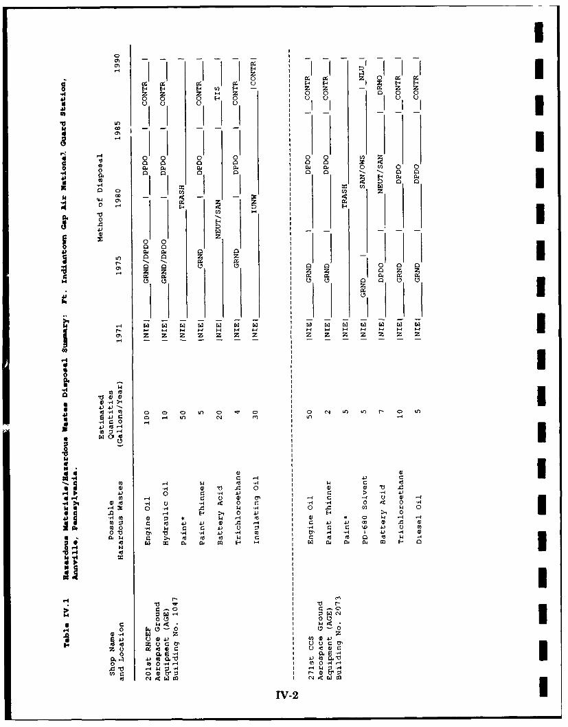
A review of Station records and interviews with personnel were used to identifyspecific operations in which the majority of hazardous materials and/orhazardous wastes are used, stored, processed, and disposed. Table IV.1provides a history of waste generation and disposal for operations conductedby shops at the Station. If an item is not listed on the table on a best-estimated basis, that activity or operation produces negligible (less than 1gallon/year) waste requiring disposal.
The potable water supply for Area 1 and Area 2 is municipal water providedby the city of Lebanon. The 26-139 OPS Facility/Compound in Area 26 obtainsits potable water from a well located at the compound. A potable water supplyis not connected to the REOTS in Area 15.
3 The buildings in Area 1 and Area 2 are connected to the sanitary sewer systemthat serves much of the greater Fort Indiantown Gap Military Reservation.Waste water flowing through this system is treated at the U.S. Army's wastewater treatment plant, which is located on the reservation and adjacent toSwatara Creek. The treated waste water is released into Swatara Creek.Sewage from the 26-139 OPS Facility/Compound flows to a subsurface sewagedisposal facility located about 40 feet northeast of the compound fence.Portable sanitation facilities are used in the REOTS area.
B. Disposal/Spill Site Information, Evaluation, and Hazard Assessment
Ten people were interviewed to identify and locate potential sites that mayhave been contaminated by hazardous wastes as a result of past Stationoperations. Three potentially contaminated sites were identified through theu interviews. These sites were visually examined in the field.
Each of these sites was rated by application of the United States Air Force(USAF) HARM (Appendix B), and since the potential for contaminant migrationexists at these three sites, each is recommended for further investigation underthe IRP program. Copies of completed HARM forms and an explanation of thefactor rating criteria used for site scoring are contained in Appendix C.
The potential exists for contaminant migration at the rated sites.Contaminants that may have been released at the sites have the potential to3 be transported by groundwater and surface water. The water table, whichaverages between 15 and 20 feet below the ground surface, has the highest riskof contamination. The fractured nature of the bedrock can provide ready access3 to the water table for contaminants. Additionally, released contaminants that
I'V-i
0 -4 l
E4 E-4 - z z z.6 ZZ Z Zj 0 0 0 04) ~0 0 0 - 00 00 0
U) I I
40 0 0 0 0 0 U
0 a, 04 I 0 0 U) 0 0.6 0 0 0 )0 C . - 0 0.0 H 0 0
4,
0 U )
0 0 0 C
000
-44
Ito V4H4 3 > 0 L > - >C A u O r
0* 4 . 4 J'O.H
*~~~- 04-4 L NI)A0) -4 w -14) r di 1 .
'3 0Vc 4 .10 A 0 K
'44) t
0 0) - . 14?7N A H . 1
W6~ w1 a4 F- low4 Ia.I '- 04 m 0 -4
V-t U~ 4) V ~ '4 4 H I HCO V D 4) 0 0
0. -V- m I 4.) (Lo404 co 0~ - '4 '0 n 0 H 0 _-I 4 -
00 4 04-0ii r I
ZCJ ~ 04)C 4W-2

- - - -- - - - - -
J' J J J I I Mpz z z z
0 0 0 0 00 0C
LA 0 D 0 0 0 a C
Z 0 c c
a0 0 0 0 00 m 0 0 = a 0
0O o io inin-
zz
z z z z z z z z 0-u' 1A0 0 0 0 0n
r-a 4C 14 0 4 I
I;~ 0
H -
0 .. 0 0-A L A H 0 ) 0 4. LA 0 L r. L ' 0 LEJJ LA to 0 '1 a m LA 0
H c H r. t)H t.) r Iy ) 4 H0 c4
t H H D) :3 z 0 - 0 HH1 0y H C
-4m H. 01 4 01 :j .-' 0
m 0 c 4) HH > 0 H 0' ) c , C- Ho V 4 co 0m0 A 40 -'4 r. 0 0) -,I 4.J w 0 H 0 4) 0) H 4)
0 oSy .) .4 m to ~ (a 4 0l - 4 5 10 H C 14 ra 1 01to to 0- & - 4 M - -
4) 04' I N
v.. 4 .)
0 -,4 - -
0 4J HH- . - -
0 4 . 0 :1
IV-3

- - -I - - - - - - -D &0 E-4 P- H -
di0~0 0 0 00) o
> I
A- I:E-0
U) 0 0 t
04. 0 C, a 0 11
zzI
00
-9-
t" o )44
LA4. -A L L 0 VA -4 C) L L A L - -
SO LA I - Q ~ -0 f-4 A m 4 LA to O4
C:4) to 4) : 4 t o k A 4 ) c t
to -W
024)C/4) C: 4
A~ 0 f-.,
di~ ~ .- 4 4) 0a N ) 0z- ~ ' a
.0 10 -4 cU 0 C) ..4L
4)-44

0~ 0
0 00
0~ ~ 00 - -
1 4 04 g 0ol to 0- U) 0 r
r.4 0 0 c0 10 0~ 10C
Q, 0 4 E4 0
4=4 CA0.=
.0
0)
H4 1- H H
* d 4O 0 0 0> 0 Lo C'=4 0 0, 0C: 0 LO LI) 0 .4 C') CV ULA C14
02 -
-441) 0 4)
r.. 02 0a)4 0 > 1 4
41 > 1 -4~ U) -,4v m0 4) -4 0 ) 0 :3
to 4 --H 0- 4.) 4 0 .02 U D ) > 4 ru 2 -
0 0 t~ V- oc 0 -4 4 4 ) 4a0 4 r. 0 o 4 .4.) >1 4 44 w- .-4 4)
.4 0 w4* IIIMIo

.44.44 0 44
44 4-0
a 0o
00
3 ~ -4 4.)
0 44 w-
02
to 0~ w . C
.0) 4. 0
0
02 4 1 3 ) 44"0 ) 014 W - 4r
4.) 02 o r . 4 ) .w m m 1
S4) 64 04 4 . 4) . 1 )4)Eo ) -4 o".4 W (
0.40 il1 4m- - ) r0 0 t 0-AA( 4)r r
4. 00) (4 .) k14 0 ; 0 C.
H" 04 , 4) m -r.0 4) 4 0 w U0.4. 0 mm wt 00. 4 . .)4
0 0 4.o 02 C 40 m: L0r4004
4 10 4) Hw n : '. 0 44) : lr
40 0204. W-4 0 4* 3 w
c 0 04 .0 0 ) 404.X) 4)( 4)4.
0 41 V r.> 0"4 ~ m w r.
.88 2 0.0 44H 0 JJ40J0 . 02m 4
0 0 0 10.1440'4 H 44) c _ r
IV > 4 0 C~ 0I 0p
C 0 V 4)4.) 0 4 I 4) 0 -24 0 ,0
440 0 2" 0 02x- 0 c 02 c 0 c
4.44.V1 14-4 04 r4 0 o4. -4 -4 J0 -
~m 00 0, 0.0 0.0 0 0,0 0 0( 0 V 0) 0M 094 0 0) 0D V) CL CLAV4CC 20M20V20 4J) V 4J V V0 43.4 4 V44.0V0M0M
4114 44 444! III 111 14
-ri oc
toM L ooto 0 0
TV-I

I
I are exposed on the ground surface have the potential to be transported bysurface water migration into Qureg Run and ultimately Swatara Creek.
I Locations for the three rated sites are provided on Figures IV.1A and IV.lB.The following items are descriptions of the potential sites identified at the
* Station:
Site No. 1 - Compound Access Road/Parking Lot (HAS-69)
3 Site No. 1 is located inside of the large, fenced compound for the 271st CCSVehicle Maintenance and AGE Shops and the 211th EIS Vehicle MaintenanceShop. The entire compound is in Area 2.
The site consists of the current access road that begins at the north fence gateas a paved surface and proceeds south-southeast into the other major portionof the site, a large (440 feet x 300 feet) vehicle parking lot. The south portionof the access route and the parking lot are covered with crushed limestone.
From 1973 to 1977, waste oil admixed with paint thinner, trichloroethane, PD-680 solvent, and diesel fuel from the 271st CCS Vehicle Maintenance and AGEShops was sprayed on the entire access road and on areas between rows ofparked vehicles in the large parking lot. The oil was applied to the currentcrushed stone that covers the area to settle dust. The spraying rig consistedof trailer mounted drums with an attached spray bar. A forklift was used to3 pull the trailer.
Spraying was done two or three times each summer, and 110 gallons of wastewere used for each spraying. Over a four-year period, as many as 1320 gallonsof waste may have been sprayed on the access road and parking lot.
There is now no visible evidence of the applied oil. No stressed vegetation ispresent in the area.
In addition to the spraying, a small waste engine oil spill from a parkedvehicle occurred in 1985. Approximately 40 gallons of this oil was spilled inthe east central portion of the parking lot.
3 Given the possibility of soil and groundwater contamination from the wastesdisposed of at this site, a HAS was calculated. A moderate quantity release
* was entered into the calculations.
Site No. 2 - Waste Holding Area (HAS-68)
The current waste holding area for the 201st RHCEF Vehicle Maintenance andAGE Shop measures approximately 20 feet north-south and 6 feet east-west.It is located in Area 1 along the perimeter fence near the southeast corner of
* IV- 7
I I.

OC:?
106 :'. Vs
35 FRI!09 ;oi
/ Waste Holding Area
LEGENDIBuildings
Fence x- X-
Prope"t Line S f.
Roads/Parking Lots ___
Site Location
SOURCE: Worcester ANG Station. Worcester, Mdassachusett. ANG Development Plan, 1989.
Figure 1V.A UPotential Sites at the Fort3
Indiantown Gap Air National Guard Station -- Area 1
IV-8I

III
Si- Nn 3* -. it N. I
II
3it, n.3 it0N .
01 Wr. te Holding Area ccess
Roa/Pakin Lot
i LEGENDBuildings ///////.
I Fence • •
Property Line S.-.-
0 _t
0oad1dP4n aAg Lots n
ISite Location ::::e:e:e:O:*:*:: : 6
SOURCE: Woreser ANG Station. Worcester, Massachusetts. ANG Development Plan, 1989.
I Figure IV.B
oPotential Sites at the Fort
Indiantown Gap Air National Guard Station -- Area 2
I IV-9

I
Building 1063 (Figure IV.1A). Since 1980, this area has been used to Itemporarily store liquid waste for pickup and disposal.
In Site No. 2, waste oil, transmission fluid, brake fluid, unleaded MOGAS, idiesel fuel, leaded and unleaded MOGAS, paint thinner, and trichloroethaneare stored in drums resting on wooden pallets. The pallets are sitting on abed of crushed stone.
Numerous small spills have been associated with the filling of drums in thisarea. Twenty-five drums are filled with waste at this location each year, and 3it is estimated that approximately one gallon of waste is spilled during theoverall filling of each drum. This would indicate that 250 gallons of wastehave been spilled in this small area over a 10-year period. The immediatereceptors of these spills were the pallets, the crushed stone beneath them, andthe shaley soil that underlies the crushed stone. Heavy, black oil staining isvisually evident on the crushed stone throughout the site.
In 1985, the waste in two of the drums tested positive for polychlorinatedbiphenyls (PCB) contamination. The PCB concentrations were 187 ppm in onedrum and 163 ppm in the other. These drums were not leaking, but, if theywere filled within the confines of the site, as many as two gallons of wastecontaminated with PCBs may have been spilled. The source of the PCBs inthese drums is unknown.
There is a potential for soil and groundwater contamination from the smallquantity (less than 1100 gallons) of wastes spilled at this site. For this reason,a HAS was calculated.
Site No. 3 - Old Waste Holding Area (HAS-61) iThe Old Waste Holding Area for the 271st Vehicle Maintenance Shop andAGE Shop measures approximately 20 feet north-south by 8 feet east-west. Itis located inside of the large, fenced vehicle maintenance/AGE compound inArea 2. Within this compound, the site is located along the fence line westof the north end of Building 2073 (Figure IV.1B). From 1975 to 1986, this Iarea was used to temporarily store liquid wastes for eventual pickup anddisposal.
Drums containing waste oil and some admixed PD-680 solvent, diesel fuel,trichloroethane, and paint thinner were stored at Site No. 3. These drumsrested on wooden pallets. Decayed wooden pallets are still located along the 3fence line in this area.
Approximately eight full drums accumulated at this location during each year. ISmall spills occurred as the drums were filled, and at least 0.5 gallons ofliquid waste per drum may have been spilled during the filling process. Someof the drums stored in this area were open and overflowed during periods of 3
IV-10i
I

I
I precipitation. Black oil stains were once visible in the shaley soil beneath thepallets, but there is no clear visual evidence of these stains now.
i The exact quantities of waste oil, fuel, and organic solvents spilled at thispotential site are unknown. For the purpose of calculating a HAS for thispotential site, a small quantity (1100 gallons or less) is used.
C. Other Pertinent Facts
o Trash and nonhazardous solid wastes from the Station are collected anddisposed of by U.S. Army personnel stationed at Fort Indiantown Gap.
o An old U.S. Army landfill is located immediately southwest of theREOTS area. This landill was in operation from 1942 to 1982. Trashfrom the Station was probably disposed of at this location from 1971 to1982. There are currently eleven monitoring wells at the landfill.
o Building 1071 was built atop the location of the old liquid waste holdingarea for the 201st RHCEF Vehicle Maintenance and AGE Shops. Fieldobservations indicated that soil had been removed to construct thebuilding. No oil stains or other evidence of contamination were observedat this location.
0 Small quantities (less than 150 gallons) of liquid wastes have been usedas herbicides along portions of the fence surrounding the major activitycenters for the 201st RHCEF (Vehicle Maintenance and AGE Shops) inArea 1 and the 211th EIS/271st CCS in Area 2.
o Very small quantities of waste solvents such as paint thinner,trichloroethane, and PD-680 have been disposed of on the crushed stoneI or ground surfaces in the immediate vicinity of the 201st RHCEF AGEShop, the 211th EIS/271st CCS Vehicle Maintenance Shop, and the 271stCCS AGE Shop.
o In the Autumn of 1989, an abandoned drum of PD-680 solvent wasdiscovered resting on soil and vegetation at the edge of a wooded arealocated approximately 150 feet west of Building 2091. The drum wasnearly full at the time of its discovery. However, a small area ofstressed vegetation around the drum was attributed to some leakage ofsolvent.
o There are six abandoned underground storage tanks (UST) at theStation. Two abandoned 5000 gallon MOGAS and diesel fuel tanks arelocated immediately north of Building 1061 in Area 1. Four abandoned5000 gallon MOGAS and diesel USTs are at the locations of former
i Iv- 11I!yl

I
fueling stations in Area 2. They are located immediately south of iBuildings 2071 and 2072 and in the northern portion of Site No. 1.
These tanks were installed around 1960 and abandoned prior to 1971. iPrior to abandonment, the fuel was pumped out, and they were filledwith water. Residual fuel is floating on top of the water in two of thetanks in Area 2. There is no available evidence that any of the six fuel Itanks have leaked.
o Four OWSs are in use at the Station. Two of these are located at 3Buildings 1046 (Fuel Station) and 1048 (201st RHCEF VehicleMaintenance Shop) in Area 1. The other two are located at Building2073 (271st CCS/211th EIS Vehicle Maintenance Shops) and at Building2070 (Fuel Station/Vehicle Wash Rack) in Area 2.
These OWSs are connected to the sanitary sewer system. They arechecked every six months and cleaned as needed. i
o On October 2, 1981, a leaking transformer was discovered south ofBuilding 2078 in Area 2. The dielectric fluid in this transformer wastested for PCBs. A PCB concentration of <1.0 ppm indicated that it wasnot a PCB transformer. It was removed from service and replaced byanother non-PCB transformer.
The U.S. Army at Fort Indiantown Gap owns the transformers on theStation lease area and is responsible for maintaining them. During the1980s, the U.S. Army conducted a comprehensive testing program toidentify PCB transformers on post property, including the Station. PCBtransformers identified through this program were replaced with non-PCB transformers by October 1986. Currently no PCB transformers existon the Station lease areas.
There are no capacitors on the Station lease areas; therefore, no PCBcapacitors exist on the Station.
0 The Station is not required to have a National Pollutant DischargeElimination System Permit.
0 The Station has a Spill Prevention, Control, and Countermeasures Planand a Spill Prevention and Response Plan.
UI
IV- 12i
I

I
I V. CONCLUSIONS
i Information obtained through interviews with ten past and present Stationpersonnel, reviews of records, and field observations was used to identify possiblespill or disposal sites on the Station property. Three potentially contaminatedsites were identified.
The following sites exhibit the potential for contaminant migration through surfacewater, soil, and/or shallow groundwater:
o Site No. 1 - Compound Access Road/Parking Lot (HAS-69)
o Site No. 2 - Waste Holding Area (HAS-68'
o Site No. 3 - Old Waste Holding Area (HAS-61)
IIIIIIIIIII V-I
I
I
I VI. RECOMMENDATIONS
I The PA identified three potentially contaminated sites. As a result, additionalwork under the IRP is recommended for these sites to confirm the presence orabsence of contamination.
IIIIIIIIIIIII* VIw-1
I
II
BIBLIOGRAPHYICarswell, L. D. et al. Geology and Hydrology of the Martinsburg
Formation in Dauphin County, Pennsylvania. PennsylvaniaGeological Survey, Bulletin W 24, 1968.
Commonwealth of Pennsylvania, Department of Environmental Resources.The State Water Plan Subbasin 7 Lower Susquehanna River.Office of Resources Management Bureau of Resources ProgrammingSWP-8, Harrisburg, 1980.
Epstein, J. B. et al. Significance of Lower Ordovician Exotic Blocks in theHamburg Klippe, Eastern Pennsylvania. United States GeologicalSurvey, Professional Paper 800-D, p. D29-D36, 1972.
Federal Emergency Management Agency. Flood Insurance Rate MapTownship of Union, Pennsylvania Lebanon County. National FloodInsurance Program, Community-Panel Number 421806 0015 A,
1979.
Geyer, A. R. et al. Geology of the Lebanon Quadrangle, PennsylvaniaGeological Survey, 4th ser., Atlas 167c, 1958.
Gray et al. Geology of the Richland Quadrangle, Pennsylvania GeologicalSurvey, 4th ser., Atlas 167d, 1958.
I Kay, G. M. Taconic Allochthone and the Martic Thrust, Science, new ser.,v. 94, p. 73, 1941.
I Pennsylvania Geological Survey. Atlas of Preliminary Geologic QuadrangleMaps of Pennsylvania. Map 61, Indiantown Gap Quadrangle,3 1981.
Royer, D. W. Summary Groundwater Resources of Lebanon County,Pennsylvania. Pennsylvania Geological Survey, Water ResourceReport 55, 1983.
Stuart, W. T. et al. Swatara Creek Basin of Southeastern Pennsylvania:An Evaluation of Its Hydrologic System. United States GeologicalSurvey, Water Supply Paper 1829, 1967.
United States Department of Agriculture USDA: Soil ConservationService. Soil Survey of Lebanon County, Pennsylvania. 1981.
II Bi-1
I
I
BIBLIOGRAPHY (continued) I
United States Department of Commerce. Climatic Atlas of the United IStates. National Climatic Center, Ashville, North Carolina, 1979.
United States Department of Commerce. Rainfall Frequency Atlas of the IUnited States. Technical Paper No. 40, U.S. Government PrintingOffice, Washington, D.C., 1963. i
United States Environmental Protection Agency. Federal RegulationsCERCLA Pollution Contingency Plan. 55 FR 8813, FederalRegistry, Washington, D.C., March 8, 1990.
United States Geological Survey (USGS). Indiantown Gap Quadrangle(Pennsylvania). 7.5 Minute Series (Topographic), 1977.
Wood, C. R. and D. B. MacLachlan. Geology and Groundwater Resourcesof Northern Berks County, Pennsylvania, Pennsylvania GeologicalSurvey, 4th ser., Water Resource Report 44, p. 91, 1978.
IIIIIIIII
Bi-2i
I

U
I GLOSSARY OF TERMS
3 ALLOCHTHONOUS - Said of rocks or materials formed elsewhere than intheir present place; of foreign origin.
3 ALLUVIAL - Pertaining to or composed of alluvium or deposited by a streamor running water.
3 ALLUVIUM - A general term for detrital deposits made by streams on riverbeds, flood plains, and alluvial fan. The term applies to stream deposits ofrecent time.
ANNUAL PRECIPITATION - The total amount of rainfall and snowfall forthe year.
ANTICLINE - A fold, generally convex upward, whose core contains thestratigraphically older rocks.
AQUICLUDE - A body of rock that will absorb water slowly but will nottransmit it fast enough to supply a well or spring.
I AQUIFER - A body of rock that is sufficiently permeable to conductgroundwater and yield economically significant quantities of water to wells and3 springs.
ARGILLACEOUS - Like or containing clay.
I ARTESIAN AQUIFER - A water-bearing bed that contains water underhydrostatic pressure.
U BASIN - (a) A depressed area with no surface outlet; (b) A drainage basin orriver basin; (c) A low area in the Earth's crust, of tectonic origin, in whichsediments have accumulated.
BAY - A wide, curving open indentation, recess, or inlet of a sea or lake intothe land or between two capes or headlands, larger than a cove, and usuallysmaller than, but of the same general character as a gulf.
BED [stratig] - The smallest formal unit in the hierarchy of lithostratigraphicunits. In a stratified sequence of rocks, it is distinguishable from layers aboveand below. A bed commonly ranges in thickness from a centimeter to a fewmeters.
BEDDING [stratig] - The arrangement of sedimentary rock in beds or layersof varying thickness and character.
GI-1Gi-U

BEDROCK - A general term for the rock, usually solid, that underlies soil or Iother unconsolidated, superficial material.
BOULDER - A detached rock mass larger than a cobble, having a diametergreater than 256 mm, being somewhat rounded or otherwise distinctly shapedby abrasion in the course of transport.
CALCAREOUS - Containing calcium carbonate.
CARBONATE - (a) A mineral compound characterized by a fundamental anionicstructure of CO3 . (b) A sediment formed of the carbonates of calcium,magnesium and/or iron, e.g. limestone and dolomite.
CLASTIC - Pertaining to a rock or sediment composed principally of fragments Uderived from pre-existing rocks or minerals and transported some distance fromtheir places of origin.
CLAY [soil] - A rock or mineral particle in the soil having a diameter less than0.002 mm (2 microns).
CLAY [geol] - A rock or mineral fragment or a detrital particle of anycomposition smaller than a fine silt grain, having a diameter less than 1/256mm (4 microns).
COARSE-TEXTURED (light textured) SOIL - Sand or loamy sand.
CONE OF DEPRESSION - The depression of heads around a pumping wellcaused by the withdrawal of water.
CONFINED AQUIFER - An aquifer bounded above and below by impermeablebeds, or by beds of distinctly lower permeability than that of the aquifer itself.
CONGLOMERATE - A coarse-grained sedimentary rock, composed of roundedpebbles, cobbles, and boulders, set in a fine-grained matrix of sand or silt, andcommonly cemented by calcium carbonate, iron oxide, silica, or hardened clay.
CONSOLIDATION - Any process whereby loosely aggregated, soft, or liquidearth materials become firm and coherent rock; specif. the solidification of amagma to form an igneous rock, or the lithification of loose sediments to forma sedimentary rock.
CONTAMINANT - As defined by Section 101(f)(33) of Superfund Amendmentsand Reauthorization Act of 1986 (SARA) shall include, but is not limited to anyelement, substance compound, or mixture, including disease-causing agents,which after release into the environment and upon exposure, ingestion,inhalation, or assimilation into any organism, either directly from the
GI-2I
I
U
environment or indirectly by ingestion through food chains, will or mayreasonably be anticipated to cause death, disease, behavioral abnormalities,cancer, genetic mutation, physiological malfunctions (including malfunctions inreproduction), or physical deformation in such organisms of their offspring;except that the term "contaminant" shall not include petroleum, including crudeoil or any fraction thereof which is not otherwise specifically listed ordesignated as a hazardous substance under:
(a) any substance designated pursuant to Section 311(b)(2XA) of the3 Federal Water Pollution Control Act,
(b) any element, compound, mixture, solution, or substancedesignated pursuant to Section 102 of this Act,
(c) any hazardous waste having the characteristics identified underor listed pursuant to Section 3001 of the Solid Waste DisposalAct (but not including any waste the regulation of which underthe Solid Waste Disposal Act has been suspended by Act of
* Congress),
(d) any toxic pollutant listed under Section 307(a) of the Federal* Water Pollution Control Act,
(e) any hazardous air pollutant listed under Section 112 of theClean Air Act, and
(f) any imminently hazardous chemical substance or mixture withrespect to which the administrator has taken action pursuantto Section 7 of the Toxic Substance Control Act;
and shall not include natural gas, liquefied natural gas, or synthetic gas ofI pipeline quality (or mixtures of natural gas and such synthetic gas).
CREEK - A term generally applied to any natural stream of water, normallylarger than a brook but smaller than a river.
CRITICAL HABITAT - The specific areas within the geographical area occupiedby the species on which are found those physical or biological features (I)essential to the conservation of the species and (II) which may require specialmanagement consideration or protection.
I CUESTA - An asymmetrical ridge, with a long, gentle slope on one sideconforming with the dip of the underlying strata, and a steep or clifflike faceon the other side formed by the outcrop of the resistant beds.
IGI-3
II

n
DEPOSITS - Earth material of any type, either consolidated or unconsolidated, Ithat has accumulated by some natural process or agent.
DIABASE - An intrusive rock whose main components are labradorite and n
pyroxene and which is characterized by ophitic texture.
DIORITE - A group of igneous rocks composed of dark-colored amphibole (esp.hornblende) oligoclase, andesine, pyroxene, and small amounts of quartz; theintrusive equivalent of andesite.
DIP - The angle that a stratum or any planar feature makes with thehorizontal, measured perpendicular to strike and in the vertical plane.
DOLOMITE - A sedimentary rock consisting of calcium magnesium carbonate,CaMg(CO) 2. Occurs in beds formed by the alteration of limestone.
DRAINAGE CLASS (natural) - Refers to the frequency and duration of periodsof saturation or partial saturation during soil formation, as opposed to altereddrainage, which is commonly the result of artificial drainage or irrigation butmay be caused by the sudden deepening of channels or the blocking of drainageoutlets. Seven classes of natural soil drainage are recognized:
Excessively drained - Water is removed from the soil very rapidly. Ex--cessively drained soils are commonly very coarse textured, rocky, or shallow.Some are steep. All are free of the mottling related to wetness.
Somewhat excessively drained - Water is removed from the soil rapidly.Many somewhat excessively drained soils are sandy and rapidly pervious.Some are shallow. Some are so steep that much of the water they receiveis lost as runoff. All are free of the mottling related to wetness.
Well-drained - Water is removed from the soil readily, but not rapidly. It n
is available to plants throughout most of the growing season, and wetnessdoes not inhibit growth of roots for significant periods during most growingseasons. Well-drained soils are commonly medium textured. They are Imainly free of mottling.
Moderately well drained - Water is removed from the soil somewhat slowlyduring some periods. Moderately well drained soils are wet for only a shorttime during the growing season, but periodically for long enough that mostmesophytic crops are affected. They commonly have a slowly pervious layer Iwithin or directly below the solum, or periodically receive high rainfall, orboth.
IGI-4
II

U
I Somewhat poorly drained - Water is removed slowly enough that the soilis wet for significant periods during the growing season. Wetnessq markedlyrestricts the growth of mesophytic crops unless artificial drainage isprovided. Somewhat poorly drained soils commonly have a slowly perviouslayer, a high water table, additional water from seepage, nearly continuousrainfall, or a combination of these.
Poorly drained - Water is removed so slowly that the soil is saturatedperiodically during the growing season or remains wet for long periods.Free water is commonly at or near the surface for long enough periodsduring the growing season that most mesophytic crops cannot be grownunless the soil is artificially drained. The soil is not continuously saturatedin layers directly below plow depth. Poor drainage results from a highwater table, a slowly pervious layer within the profile, seepage, nearlycontinuous rainfall, or a combination of these.
I Very poorly drained - Water is removed from the soil so slowly that freewater remains at or on the surface during most of the growing season.Unless the soil is artificially drained, most mesophytic crops cannot begrown. Very poorly drained soils are commonly level or depressed and arefrequently ponded. Yet, where rainfall is high and nearly continuous, theycan have moderate or high slope gradients, as for example in "hillpeats" and"climatic moors."
DRAINAGEWAY - A channel or course along which water moves in drainingan area.
ENDANGERED SPECIES - Any species which is in danger of extinctionthroughout all or a significant portion of its range, other than a species of theClass Insecta determined by the secretary to constitute a pest whose protectionwould present an overwhelming and overriding risk to man.
EROSION - The general process or the group of processes whereby thematerials of the Earth's crust are loosened, dissolved, or worn away, andsimultaneously moved from one place to another by natural agencies, butusually exclude mass wasting.
FELDSPAR - Any of several crystalline minerals made up of aluminumsilicates with sodium, potassium, or calcium, usually glassy and moderatelyhard, found in igneous rocks.
I FELDSPATHIC - Like or as feldspar.
FERRUGINOUS - Pertaining to or containing iron.
FINE-GRAINED - Said of a soil in which silt and/or clay predominate.
IGI-5
II
i
FINE-TEXTURED (heavy textured) SOIL - Sandy clay, silty clay, and clay. 3FLOOD PLAIN - The surface or strip of relatively smooth land adjacent to ariver channel, constructed by the present river in its existing regimen and 3covered with water when the river overflows its banks.
FOLD [geol struc] - A curve or bend of a planar structure such as rock strata,bedding planes, foliation or cleavage. IFORMATION - A lithologically distinctive, mappable body of rock.
FOSSILIFEROUS - Containing fossils.
FRACTURE [struc geol] - A general term for any break in a rock, whether or inot it causes displacement, due to mechanical failure by stress. Fractureincludes cracks, joints, and faults.
GABBRO - A group of dark-colored, basic intrusive igneous rocks composedprincipally of basic plagioclase and clinopyroxene, with or without olivine andothoxypyrene; approximate intrusive equivalent of basalt.
GEOLOGIC TIME - See Figure G1.1 3GLAUCONITIC SANDSTONE - Greensand, composed of a green mineral,closely related to the micas and essentially a hydrous potassium iron silicate.
GNEISS - A coarse-grained, foliated rock produced by regional metamorphism;commonly feldspar- and quartz-rich.
GRANITE - Broadly applied, any crystalline, quartz-bearing plutonic rock; alsocommonly contains feldspar, mica, hornblende, or pyroxene.
GRANODIORITE - A group of coarse-grained plutonic rocks intermediate incomposition between quartz diorite and quartz monzonite, containing quartz,plagioclase, and potassium feldspar with biotite, horneblende, or more rarely, 3pyroxene, as the mafic contents.
GRAVEL - An unconsolidated, natural accumulation of rounded rock fragmentsresulting from erosion, consisting predominantly of particles larger than sand,such as boulders, cobbles, pebbles, granules or any combination of thesefragments. 3GRAYWACKE - A non-porous, dark-colored sandstone containing angular grainsand fragments of other rocks; a fine-grained conglomerate resemblingsandstone.
G1-6i
I

UI
The Geologic Time Scale(Numbers are in millions
of years before the present)
Eon Era Period Epoch
Recent or
Ouaternary Holocene
Pleistocene
2Pliocene I
Neogene 5Miocene
o 0 24Oligocene
Paleogene Eocene
586 Paleocene 5I56
Cretaceousu 144-
0 Jurassic0N 208-Z TriassicI 245-
(L Permian286
Pennsylvanian
-320-
Mississippian
360-
0N DevonianRM408-n. Silunan
438-
I Ordovican 505-
Cambrian
* 570-
Proterozoic Eon PrecambnanComprsesIAbout
E87%of the
- 2500 GeologicTime Scale
Archean Eon 3"' 3800-
NO Record Ogin of Earth
I Figure Gl.1
I The Geologic Time Scale
GI.7
i
GROUNDWATER - Refers to the subsurface water that occurs beneath thewater table in soils and geologic formations that are fully saturated.
HARM - Hazard Assessment Rating Methodology - A system adopted and used 3by the United States Air Force to develop and maintain a priority listing ofpotentially contaminated sites on installations and facilities for remedial actionbased on potential hazard to public health, welfare, and environmental impacts.(Reference: DEQPPM 81-5, December 11, 1981.)
HAS - Hazard Assessment Score - The score developed by using the HazardAssessment Rating Methodology (HARM).
HAZARDOUS MATERIAL - Any substance or mixture of substances havingproperties capable of producing adverse effects on the health and safety of the Ihuman being. Specific regulatory definitions also found in OSHA and DOTrules.
HAZARDOUS WASTE - A solid or liquid waste that, because of its quantity,concentration, or physical, chemical, or infectious characteristics may:
P. cause, or significantly contribute to, an increase in mortality oran increase in serious or incapacitating reversible illness, or
b. pose a substantial present or potential hazard to human healthor the environment when improperly treated, stored,transported, disposed of, or otherwise managed.
HERBICIDE- A weed killer.
HIGHLAND - A general term for a relatively large area of elevated ormountainous land standing prominently above adjacent low areas; andmountainous region. IHILL - A natural elevation of the land surface, rising rather prominently abovethe surrounding land, usually of limited extent and having a well-defined Ioutline (rounded) and generally considered to be less than 1000 feet from baseto summit.
IGNEOUS ROCKS - Rock or mineral that has solidified from molten orpartially molten material, i.e. from magma.
INTERBEDDED - Beds lying between or alternating with others of differentcharacter; especially rock material laid down in sequence between other beds.
GI-8i
UI

I
I KARST - A type of topography that is formed over limestone, dolomite,orgypsum by dissolution, and that is characterized by sinkholes, caves andunderground drainage.
KLIPPE - An isolated mass of rock that is an erosional remnant or outlier ofa nappe.
LIMESTONE - A sedimentary rock consisting of the mineral calcite (calciumcarbonate, CaCo3 ) with or without magnesium carbonate.
LIMONITE - A common secondary material, formed by weathering (oxidation)of iron-bearing materials.
LITHOLOGY - (a) The description of rocks. (b) The physical character of arock.
LOAM - A rich, permeable soil composed of a friable mixture of relatively equalproportions of sand, silt, and clay particles, and usually containing organic
I matter.
LOWLAND - A general term for low-lying land or an extensive region of lowland, especially near the coast and including the extended plains or countrylying not far above tide level.
MARBLE - A metamorphic rock consisting predominantly of fine- tocoarse-grained recrystallized calcite and/or dolomite, usually with granoblastic,saccharoidal texture.
I MARSH - A water-saturated, poorly drained area, intermittently orpermanently water-covered, having aquatic and grasslike vegetation, essentially
I without the formation of peat.
MEAN LAKE EVAPORATION - The total evaporation amount for a particularI area; amount based on precipitation and climate (humidity).
METAMORPHIC ROCK - Any rock derived from pre-existing rocks bymineralogical, chemical, and/or structural changes, essentially in solid state, in
I response to marked changes in temperature, pressure, shearing stress, andchemical environment, generally at depth in the Earth's crust.
MIGRATION [Contaminant] - The movement of contaminants through pathways(groundwater, surface water, soil, and air).
MINERAL - A naturally occurring inorganic element or compound having anorderly internal structure and characteristic chemical composition, crystal formand physical properties.
II

i
MOTTLED [soil] - A soil that is irregularly marked with spots or patches of idifferent colors, usually indicating poor aeration or seasonal wetness.
NAPPE - A sheetlike, allochthonous, folded rock unit in which the axial planeis horizontal or subhorizontal. The mechanism may be thrust faulting,recumbent folding, or gravity sliding.
NET PRECIPITATION - Precipitation minus evaporation.
OUTCROP - That part of a geologic formation or structure that appears at thesurface of the Earth; also, bedrock that is covered only by surficial depositssuch as alluvium.
OVERTURNED - Said of a fold or the limb of a fold, that has tilted beyondthe perpendicular sequence of strata and thus appears reversed.
PD-680 - A cleaning solvent composed predominately of mineral spirits; iStoddard solvent.
PEAT - An unconsolidated deposit of semicarbonized plant remains in a iwater-saturated environment and of persistently high moisture content (at least75%).
PERMEABILITY - The capacity of a porous rock, sediment, or soil fortransmitting a fluid without impairment by the structure of the medium; it isa measure of the relative ease of fluid flow under unequal pressure.
POND - A natural body of standing fresh water occupying a small surfacedepression, usually smaller than a lake and larger then a pool.
POROSITY - The ratio of the aggregate volume of interstices in a rock or soilto its total volume. IPOTENTIOMETRIC SURFACE - An imaginary surface representing the totalhead of groundwater and defined by the level to which water will rise in a Iwell. The water table is a particular potentiometric surface.
QUARTZ - A crystalline silica, an important rock forming mineral: SiO2 .Occurs either in transparent hexagonal crystals (colorless or colored byimpurities) or in crystalline. Forms the major proportion of most sands andhas a widespread distribution in igneous, metamorphic and sedimentary rocks.
QUARTZITE [metal - A granoblastic metamorphic rock consisting mainly ofquartz and formed by recrystallization of sandstone or chert by either regionalor thermal metamorphism.
GI-10Giol0i
i
I
I RECUMBENT FOLD - An overturned fold in which the axial surface is moreor less horizontal.
RIVER - A general term for a natural freshwater surface stream ofconsiderable volume and a permanent or seasonal flow, moving in a definitechannel toward a sea, lake, or another river.
SALINE [adj] - Salty; containing dissolved sodium chloride.
SAND - A rock or mineral particle in the soil, having a diameter in the range0.52 - 2 mm.
SANDSTONE - A medium-grained fragmented sedimentary rock composed ofabundant round or angular sand fragments set in a fine-grained matrix (siltor clay) and more or less firmly united by a cementing material (commonlysilica, iron oxide, or calcium carbonate).
SANDY LOAM - A soil containing 43 - 85% sand, 0 - 50% silt, and 0 - 20%clay, or containing at least 52% sand and no more than 20% clay and havingthe percentage of silt plus twice the percentage of clay exceeding 30% orcontaining 43 - 52% sand, less than 50% silt, and less than 7% clay.
I SCHIST - A medium- or coarse-grained, strongly foliated, crystalline rock;formed by dynamic metamorphism.
U SCHISTOCITY - The foliation in schist or other coarse-grained, crystallinerock due to the parallel, planar arrangement of mineral grains of the platy,prismatic, or ellipsoidal types, usually mica.
SEDIMENT - Solid fragmental material that originates from weathering ofrocks and is transported or deposited by air, water, or ice, or that accumulatesby other natural agents, such as chemical precipitation from solution orsecretion by organisms, and that forms in layers on the Earth's surface atordinary temperatures in a loose, unconsolidated form; (b) strictly solid materialthat has settled down from a state of suspension in a liquid.
SEDIMENTARY ROCK - A rock resulting from the consolidation of loosesediment that has accumulated in layers; e.g., a clastic rock (such asconglomerate or tillite) consisting of mechanically formed fragments of olderrock transported from its source and deposited in water or from air or ice; ora chemical rock (such as rock salt or gypsum) formed by precipitation fromsolution; or an organic rock (such as certain limestones) consisting of theremains or secretions of plants and animals.
IU GI-11
II

I
SHALE - A fine-grained detrital sedimentary rock, formed by the consolidation I(especially by compression) of clay, silt, or mud.
SILT [soil] - (a) A rock or mineral particle in the soil, having a diameter in therange 0.002-0.005 mm; (b) A soil containing more than 80% silt-size particles,less than 12% clay, and less than 20% sand.
SILT LOAM - A soil containing 50 - 88% silt, 0 - 27% clay, and 0 - 50% sand.
SILTSTONE - An indurated silt having the texture and composition of shalebut lacking its fine lamination or fissility; a massive mudstone in which siltpredominates over clay.
SLATE - A compact, fine-grained metamorphic rock that possesses slatycleavage and hence can be split into slabs and thin plates. Most slate wasformed from shale. 3SOIL PERMEABILITY - The characteristic of the soil that enables water tomove downward through the profile. Permeability is measured as the distanceper unit time that water moves downward through the saturated soil.
Terms describing permeability are:
Very Slow - less than 0.06 inches per hour (less than 4.24 x 10'cmlsec)I
Slowsec)0.06 to 0.20 inches per hour (4.24 x 10' to 1.41 x 10'
Slow - curisec)Moderately Slow -)0.20 to 0.63 inches per hour (1.41 x 10' to 4.45 X 10'
Modeatey Slw -cmlsec)
Moderate - 0.63 to 2.00 inches per hour (4.45 x 10' to 1.41 x 10'cm/sec)
Moderately Rapid - 2.00 to 6.00 inches per hour (1.41 x 10' to 4.24 x 10'cm/sec)
Rapid -6.00 to 20.00 inches per hour (4.24 x 10' to 1.41 x 10.2cm/sec) 3
Very Rapid - more than 20.00 inches per hour (more than 1.41 x 10'cm/sec) 3
(Reference: U.S.D.A. Soil Conservation Service)GI-12
II

I
I SOIL REACTION - The degree of acidity or alkalinity of a soil, expressed inpH values. A soil that tests of pH 7.0 is described as precisely neutral inreaction because it is neither acid nor alkaline. The degree of acidity oralkalinity is expressed as:
Extremely acid Below 4.5Very strongly acid 4.5 to 5.0Strongly acid 5.1 to 5.5Medium acid 5.6 to 6.0Slightly acid 6.1 to 6.5Neutral 6.6 to 7.3Mildly alkaline 7.4 to 7.8Moderately alkaline 7.9 to 8.4Strongly alkaline 8.5 to 9.0Very strongly alkaline 9.1 and higher
SOIL STRUCTURE - The arrangement of primary soil particles into compoundparticles or aggregates that are separated from adjoining aggregates. Theprincipal forms of soil structure are -- platty (laminated), prismatic (verticalaxis of aggregates longer than horizontal), columnar (prisms with roundedtops), blocky (angular or subangular), and granular. Structureless soils areeither single grained (each grain by itself, as in dune sand) or massive (theparticles adhering without any regular cleavage, as in many hardpans).
SOLVENT - A substance, generally a liquid, capable of dissolving otherI substances.
STONE - A general term for rock that is used for construction, either crushedfor use as aggregate or cut into shaped blocks as dimension stone.
STRATIFIED - Formed, arranged, or laid down in layers or strata; especiallysaid of any layered sedimentary rock or deposit.
STRATIGRAPHIC UNIT - A body of strata recognized as a unit for description,mapping, or correlation.
STRIKE - The direction taken by a structural surface, e.g., a bedding or faultplane, as it intersects the horizontal.
STRIKE - SLIP FAULT - A fault on which the movement is parallel to thefault's strike.
II Gl-13
II

i
STRUCTURAL - Of or pertaining to rock deformation or to features that result Ifrom it.
SURFACE WATER - All water exposed at the ground surface, includingstreams, rivers, ponds, and lakes.
SWAMP - An area intermittently or permanently covered with water, havingshrubs and trees but essentially without the accumulation of peat.
SYNCLINE - A fold of which the core contains the stratigraphically youngerrocks; it is generally concave upward.
SYNCLINORIUM - A composite synclinal structure of regional extent composedof lesser folds. iTERRACE [geomorph] - Any long, narrow, relatively level or gently inclinedsurface, generally less broad than a plain, bounded along one edge by a steeperdescending slope and along the other by a steeper ascending slope.
TERRACE [soil] - A horizontal or gently sloping ridge or embankment of earth ibuilt along the contours of a hillside for the purpose of conserving moisture,reducing erosion, or controlling runoff.
THREATENED SPECIES - Any species which is likely to become anendangered species within the foreseeable future throughout all or significantportion of its range.
TIME [geol] - See Figure G1.1.
TOPOGRAPHY - The general conformation of a land surface, including itsrelief ..nd the position of its natural and man-made features.
UNCONSOLIDATED - (a) Sediment that is loosely arranged or unstratifed, orwhose particles are not cemented together, occurring either at the surface orat depth. (b) Soil material that is in a loosely aggregated form.
UNDULATING [geomorph] - (a) A landform having a wavy outline or form.(b) A rippling or scalloped land surface, having a wavy outline or appearance. iVALLEY - Any low-lying land bordered by higher ground, especially anelongate, relatively large, gently sloping depression of the earth's surface,commonly situated between two mountains or between ranges of hills andmountains, and often containing a stream or river with an outlet. It is usuallydeveloped by stream or river erosion, but can be formed by faulting.
VEIN [intrus rock] - A thin, sheetlike igneous intrusion into a fissure.
Gl-14
II
i
i WATER TABLE - The upper limit of the portion of the ground that is whollysaturated with water; the surface on which the fluid pressure in the pores ofa porous medium is exactly atmospheric.
WETLANDS - Those areas that are inundated or saturated by surface orgroundwater at a frequency and duration sufficient to support, and that undernormal circumstances do support, a prevalence of vegetation typically adaptedfor life in saturated soil conditions. Wetlands generally include swamps,
i marshes, bogs, and similar areas.
WILDERNESS AREA - An area unaffected by anthropogenic activities anddeemed worthy of special attention to maintain its natural condition.
i
II
iIiiiI
I

IIIII
U Appendix AI| Outside Agency Contact List
IIIIIIIIIII

IOUTSIDE AGENCY CONTACT LIST
1) City of Lebanon, PennsylvaniaBureau of Public Works400 South Eight StreetLebanon, Pennsylvania 17042James G. Cummings(717) 273-6711
* 2) Commonwealth of PennsylvaniaBureau of ForestryForest Advisory ServicesP.O. Box 8552Harrisburg, Pennsylvania 17105-8552Kathy McKennaEd Dix(717) 787-3444(717) 783-0392
3) Commonwealth of PennsylvaniaDepartment of Environmental Resources1 Ararat BoulevardHarrisburg, Pennsylvania 17710William Botts(717) 657-4590
4) Commonwealth of PennsylvaniaDepartment of General ServicesState BookstoreP.O. Box 1365Harrisburg, Pennsylvania 17105Patricia Chapman(717) 787-5109
I 5) Commonwealth of PennsylvaniaPennsylvania Fish CommissionDivision of Fisheries Management450 Robinson LaneBelleforte, Pennsylvania 16823-9616Clark N. Shiffer(814) 359-5113
III A-i
I

iOUTSIDE AGENCY CONTACT LIST (continued)
6) Commonwealth of PennsylvaniaPennsylvania Game Commission iBureau of Land Management2001 Elmerton AvenueHarrisburg, Pennsylvania 17110-9797Denver A. McDowell, Jr.(717) 783-8743
7) Commonwealth of Pennsylvania nTopographic and Geological SurveyDepartment of Environmental ResourcesP.O. Box 2357Harrisburg, Pennsylvania 17120Mari G. BarnhartDona SnyderDawna Yannacci(717) 787-5828
8) Dauphin Consolidated Water Supply CompanyP.O. Box 4151Harrisburg, Pennsylvania 17711 IKirby Pack(717) 232-6207 3
9) Fort Indiantown GapDirectorate of Engineering and HousingEnvironmental/Energy Office iAttn: AFKA-ZQ-DE-EAnnville, Pennsylvania 17003-5011Kenneth L. Malick I(717) 865-5444
10) HeadquartersU.S. Army GarrisonFort Indiantown GapAnnville, Pennsylvania 17003Specialist Ian Murdock(717) 865-5444 ext. 2193
11) United States Department of Agriculture (USDA) mSoil Conservation ServiceSuite 4 (Side Entrance)201 Cumberland StreetLebanon, Pennsylvania 17042Charles Wertz(717) 272-4618
A-2
I

IIIIIi Appendix B
Ii USAF Hazard Assessmentll Rating Methodology
IiiIiiiiIi
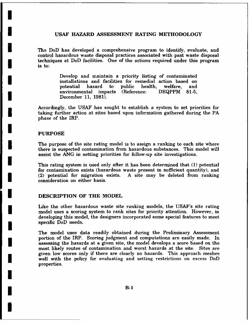
I
I USAF HAZARD ASSESSMENT RATING METHODOLOGY
i The DoD has developed a comprehensive program to identify, evaluate, andcontrol hazardous waste disposal practices associated with past waste disposaltechniques at DoD facilities. One of the actions required under this programis to:
Develop and maintain a priority listing of contaminatedinstallations and facilities for remedial action based onpotential hazard to public health, welfare, andenvironmental impacts (Reference: DEQPPM 81-5,December 11, 1981).
Accordingly, the USAF has sought to establish a system to set priorities fortaking further action at sites based upon information gathered during the PAphase of the IRP.
U PURPOSE
The purpose of the site rating model is to assign a ranking to each site wherethere is suspected contamination from hazardous substances. This model willassist the ANG in setting priorities for follow-up site investigations.
U This rating system is used only after it has been determined that (1) potentialfor contamination exists (hazardous waste present in sufficient quantity), and(2) potential for migration exists. A site may be deleted from rankingconsideration on either basis.
I DESCRIPTION OF THE MODEL
Like the other hazardous waste site ranking models, the USAF's site ratingmodel uses a scoring system to rank sites for priority attention. However, indeveloping this model, the designers incorporated some special features to meetspecific DoD needs.
The model uses data readily obtained during the Preliminary Assessmentportion of the IRP. Scoring judgment and computations are easily made. Inassessing the hazards at a given site, the model develops a score based on themost likely routes of contamination and worst hazards at the site. Sites aregiven low scores only if there are clearly no hazards. This approach mesheswell with the policy for evaluating and setting restrictions on excess DoDproperties.
I* B-1
I

I
Site scores are developed using the appropriate ranking factors presented inthis appendix. The site rating form and the rating factor guidelines areprovided at the end of this appendix.
As with the previous model, this model considers four aspects of the hazardposed by a specific site: (1) possible receptors of the contamination, (2) thewaste and its characteristics, (3) the potential pathways for contaminant Imigration, and (4) any effort that was made to contain the waste resultingfrom a spill.
The receptors category rating is based on four rating factors: (1) the potentialfor human exposure to the site, (2) the potential for human ingestion ofcontaminants should underlying aquifers be polluted, (3) the current andanticipated use of the surrounding area, and (4) the potential for adverseeffects upon important biological resources and fragile natural settings. Thepotential for human exposure is evaluated on the basis of the total populationwithin 1000 feet of the site, and the distance between the site and the baseboundary. The potential for human ingestion of contaminants is based on thedistance between the site and the nearest well, the groundwater use of theuppermost aquifer, and population served by the groundwater supply within 3miles of the site. The uses of the surrounding area are determined by thezoning within a 1-mile radius. Determination of whether or not criticalenvironments exist within a 1-mile radius of the site predicts the potential foradverse effects from the site upon important biological resources and fragilenatural settings. Each rating factor is numerically evaluated (0-3) andincreased by a multiplier. The maximum possible score is also computed. Thefactor score and maximum possible scores are totaled, and the receptorssubscore computed as follows: receptors subscore = (100 X factorsubtotal/maximum score subtotal).
The waste characteristics category is scored in three steps. First, a pointrating is assigned based on an assessment of the waste quantity and the Ihazard (worst case) associated with the site. The level of confidence in the
information is also factored into the assessment. Next, the score is multipliedby a waste persistence factor, which acts to reduce the score if the waste is=Inot very persistent. Finally, the score is further modified by the physical stateof the waste. Liquid wastes receive the maximum score while scores for solidsare reduced.
The pathways category rating is based on evidence of contaminant migrationalong one of three pathways: surface water migration, flooding, andgroundwater migration. If evidence of contaminant migration exists, thecategory is given a subscore of 80 to 100 points. For indirect evidence, 80points are assigned, and for direct evidence, 100 points are assigned. If noevidence is found, the highest score among the three possible routes is used.The three pathways are evaluated and the highest score among all four of thepotential scores is used.
B-2
I
I
i The scores for each of the three categories are added together and normalizedto a maximum possible score of 100. Then the waste management practicecategory is scored. Scores for sites with no containment are not reduced.Scores for sites with limited containment can be reduced by 5 percent. If asite is contained and well-managed, its score can be reduced by 90 percent.The final site score is calculated by applying the waste management practicescategory factor to the sum of the score for the other three categories.
[IIIIIIIIIIII* B-3
I

IHAZARD ASSESSMENT RATING FORM
NAME OF SITE
LOCATION
DATE OF OPERATION OR OCCURRENCE IOWNER/OPERATOR
COMMENTS/DESCRIPTION - ISITE RATED BY
I. RECEPTORS Factor MaximumRating Factor Possible
Rating Factor (0-3) Multiplier Score Score IA. Population within 1000 ft. of site 4 12
B. Distance to nearest well 10 30
C. Land use-zoning within 1-mile radius 3 9
D. Distance to installation boundary 6 18
E. Critical environments within 1-mile radius of site 10 30F. Water quality of nearest surface water body 6 18
G. Groundwater use of uppermost aquifier 9 27
H. Population served by surface water supply within 3 6 18miles downstream of site
I. Population served by groundwater supply within 3 6 18miles of site
Subtotals 180 I
Receptors subscore (100 x factor score subtotal/maximum score subtotalj
II. WASTE CHARACTERISTICS
A. Select the factor score based on the estimated quantity, the degree of hazard, and the confidence level ofthe information.
1. Waste quantity (S = small, M = medium, L = large)
2. Confidence level (C = confirmed, S = suspected) I3. Hazard rating (H - high, M = medium, L = low)
Factor Subscore A (from 20 to 100 based on factor score matrix) 1B. Apply persistence factor
Factor subscore A x Persistence Factor = Subscore B
x
C. Apply physical state multiplierSubscore B x Physical State Multiplier = Waste Characteristics Subscore
x = -
B-4

IIll PATHWAYS Factor Maximum
Rating Factor PossibleRating Factor (0-3) Multiplier Score Score
A. If there Is evidence of migration of hazardous contaminants, assign maximum factor subscore of 100 pointsfor direct evidence or 80 points for indirect evidence. If direct evidence exists, then proceed to C. Ifno evidence or indirect evidence exists, proceed to B. Subscore
B. Rate the migration potential for 3 potential pathways: Surface water migration, flooding, and groundwatermigration. Select the highest rating, and proceed to C.
1. Surface water migration
Distance to nearest surface water 8 24
Net precipitation 6 18
Surface erosion 8 24
Surface permeability 6 18
Rainfall intensity 8 24
Subtotals 108
Subscore (100 x factor score subtotal/maximum score subtotal)
Subscore (100 x factor score/3)
3. Groundwater migration
Depth to groundwater 8 24
Net precipitation 6 18
Soil permeability 8 24
Subsurface flows 8 24
Direct access to groundwater 118 24
Subtotals 114
Subscore (100 x factor score subtotal/maximum score subtotal)C. Highest pathway score
Enter the highest subscore value from A, B-, B-2, or B-3 above
Pathways subscore
I IV. WASTE MANAGEMENT PRACTICES
A. Average the three subscores for receptors, waste characteristics, and pathways.
ReceptorsWaste CharacteristicsPathways
Total divided by 3 =
Gross Total ScoreB. Apply factor for waste containment from waste management practices.
* Gross Total Score x Waste Management Practices Factor = Final Score
* B-5

0 a
414 -v
6
-0 w 0-~0
41 ~ ~ 4 016 6.
0 ~ ~ c -. c..U .6 101 2 - s .
6. C .Cu4~~104 ~ * p 1 . .I
41m u 410 6
q .4 jO U - 1 - .6
43 0 ~ 0 4.41 .3 ~ 0 2 0 43'A
czv
-J 0 6 0 > 1 .3-. 0 - - >.0 .- 44 1 U 4 4 1 0... 41-0rvo - - ~ ,4 1 2
41 44 16 41 . . U4
c1 be- fa.41 C U 02
0.. ra61 c u 4
-C41-7, 0 CD
41 1U, ~ ~ ~ L U, . - 1. .
.V.. ; t-I
PU 66
ui41 >3 411 a.
Z tU -00
p1 - 4141
04 4.4
a U. C a -,a
0 L 0l -.--11 -4 0
416 U4;3
B-6;

Icfo 0
C 11* ID ~ ID~>
2.- Sn I
w LIDIDI K .
e0 c -0 cwD c .Cw'.2 o DIn
0
0 C ID 'A I- I0D 0 .OIDD
U L. 0 0U 'A m
4A 0~ CIID0 ED
0 'A I I
3o 0toC Q 0 10IL~c ' I I
fn >2 2
'A InI
. t -0 IID 0 '
.- Ua
ID -
IDc C 0i
0 0 a(D I
U1 E w0 - 0 L
CD ID a
0
0 -! -C0 I
I 0 ID
ID - 7 ICA --j 2 >. 0 .
-o 0 0 I
"C.
1.
2 B-7

14,
L..
(04
aAO >.> > C
-C, U-C
(0 'C 0 0 0C>.a
L.. -U U .0 0 0
V) ~ 0 ~ z 0 Mv m
t(0 04. 1 0. 04 D0
L a.L
0 00
4A&fS( MC a ---a
C2U 4 2
C0 -Z U C "as). w 0.tO a,
a. IIL
M 0
4,.-8
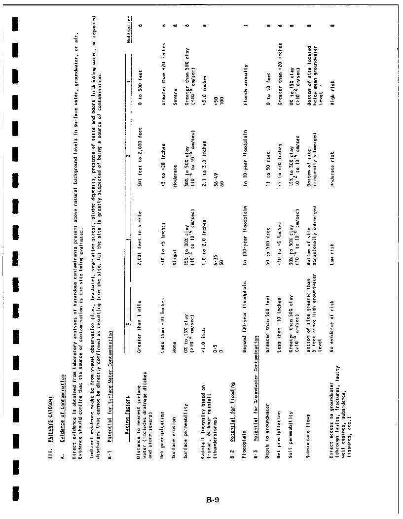
I ajL: 4
o 0 0 co
u 00
04, u --- 0-U.) 4, U .0C ,1
4) 4, 0) U)00 U) 0 "1 0 cUZ
0 ) 4,U
X ~ 0 OW 0 0Qm a- w >. u
w ) 0 vO - CD - 2 -.0~~l C ) 0 0 * 0 ) C) ~.
*0.>Uw OM.'
4,0 LM. -
0, 5)4 U . 04 .* ~ ~ C 5)4 T CU-- U 4
4, 4, 0 0 w)
0 00 0 - w
It C 0 M ) U) vE. 0 0 N 1,0 NOv -O
4,~~C - UN) 0 C - 0L- U)-uF. ) F.- 0
-. 0
m. 2
in- 40 0 -u4
75 2, - >EU
3 - --3r. O 0 > 0- 0 0. 1. 0"
wl u - CL N w'"3 li C1 L: U) 'UCC fa' m L -L .0 I
4,Z W> 0 5)4 -s00 '444
m ca -0 cc' WO)- -
C 4, 5) B-9

-C I0 V
CLe II
a. 6
-uu
2m c020
0
LUZ 0.0-
- v 0
ma. -E 0
u0 0
UIle. -I
-00 IN; 0 1U a. ~ lB-0

IIIIU
i Appendix C
I| Site Hazard Assessment* Rating Forms and Factor
| Rating Criteria
II
I
IIII
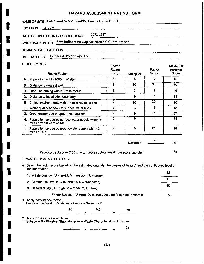
3 HAZARD ASSESSMENT RATING FORM
NAME OF SITE Compound Access Road/Parking Lot (Site No. 1)
LOCATION Area 2
DATE OF OPERATION OR OCCURRENCE 1973-1977
OWNER/OPERATOR Fort Indiantown Gap Air National Guard Station
I COMMENTS/DESCRIPTION
SITE RATED BY Science & Technology, Inc.
1. RECEPTORS Factor MaximumRating Factor Possible
Rating Factor (0-3) Multiplier Score Score
A. Population within 1000 ft. of site 3 4 12 12
B. Distance to nearest well 3 10 30 30
C. Land use-zoning within 1-mile radius 3 3 9 9
D. Distance to installation boundary 3 6 18 18
E. Critical environments within 1-mile radius of site 2 10 20 30
F. Water quality of nearest surface water body 1 6 6 18
G. Groundwater use of uppermost aquifier 2 9 18 27
3 H. Population served by surface water supply within 3 0 6 0 18miles downstream of site
I. Population served by groundwater supply within 3 2 6 12 18miles of site
125Subtotals 180
Receptors subscore (100 x factor score subtotal/maximum score subtotal) 59
I !1. WASTE CHARACTERISTICS
A. Select the factor score based on the estimated quantity, the degree of hazard, and the confidence level ofthe information.
1. Waste quantity (S = small, M = medium, L = large)C
2. Confidence level (C = confirmed, S = suspected)
3. Hazard rating (H = high, M = medium, L = low)
Factor Subscore A (from 20 to 100 based on factor score matrix) 80
I B. Apply persistence factorFactor subscore A x Persistence Factor = Subscore B
80 0.9 72x
C. Apply physical state multiplierSubscore B x Physical State Multiplier = Waste Cha:acteristics Subscore
72 x 1.0 - 72
IC-1I
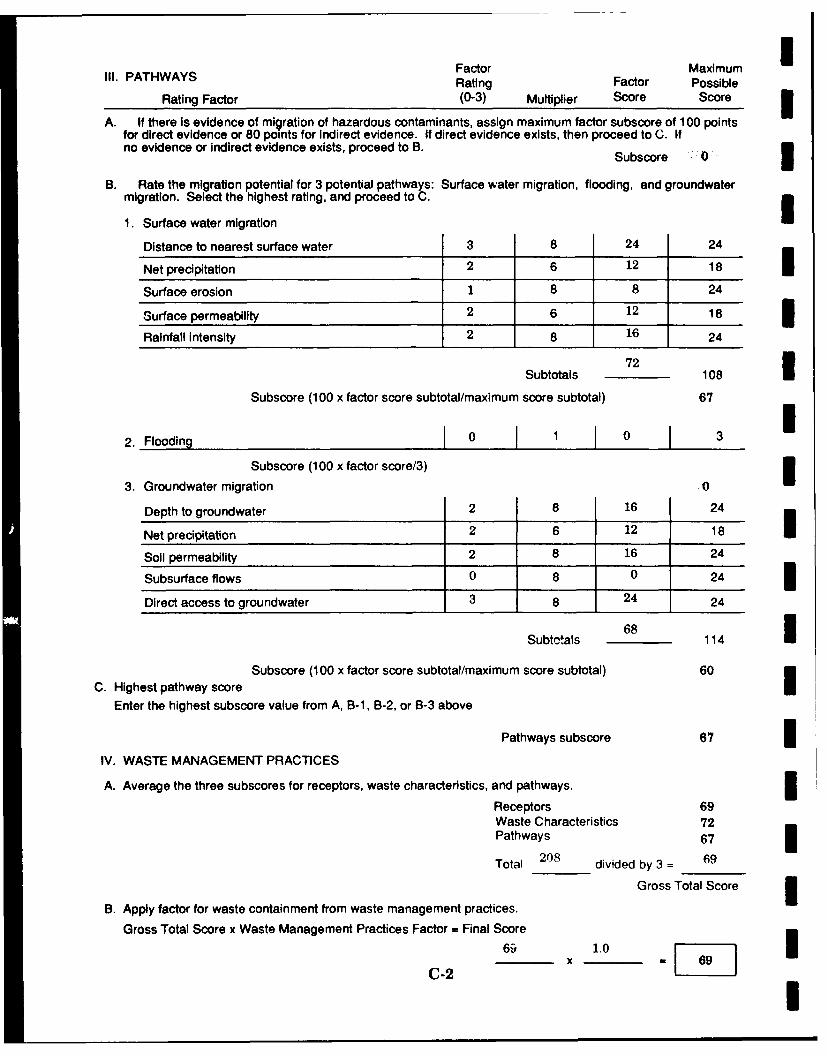
Factor MaximumIll. PATHWAYS Rating Factor Possible
Rating Factor (0-3) Multiplier Score Score
A. If there Is evidence of migration of hazardous contaminants, assign maximum factor subscore of 100 pointsfor direct evidence or 80 points for Indirect evidence. If direct evidence exists, then proceed to C. Ifno evidence or indirect evidence exists, proceed to B. Subscore 0
B. Rate the migration potential for 3 potential pathways: Surface water migration, flooding, and groundwater
migration. Select the highest rating, and proceed to C.
1. Surface water migration
Distance to nearest surface water 3 8 24 24
Net precipitation 2 6 12 18 3Surface erosion 1 8 8 24
Surface permeability 2 6 12 18 3Rainfall intensity 2 8 16 24
Subtotals 108
Subscore (100 x factor score subtotal/maximum score subtotal) 67
2. Flooding I0 1 0
Subscore (100 x factor score/3)
3. Groundwater migration 0
Depth to groundwater 2 8 16 24
Net precipitation 2 6 12 18
Soil permeability 2 8 16 24
Subsurface flows 0 8 0 24 3Direct access to groundwater 3 8 24 24
Subtotals 68 114
Subscore (100 x factor score subtotal/maximum score subtotal) 60C. Highest pathway scoreI
Enter the highest subscore value from A, B-1, B-2, or B-3 above
Pathways subscore 67 3IV. WASTE MANAGEMENT PRACTICES
A. Average the three subscores for receptors, waste characteristics, and pathways.
Receptors 69Waste Characteristics 72Pathways 67 3Total 208 divided by 3 = 69
Gross Total Score 3B. Apply factor for waste containment from waste management practices.
Gross Total Score x Waste Management Practices Factor = Final Score
S1.0
C-2 I
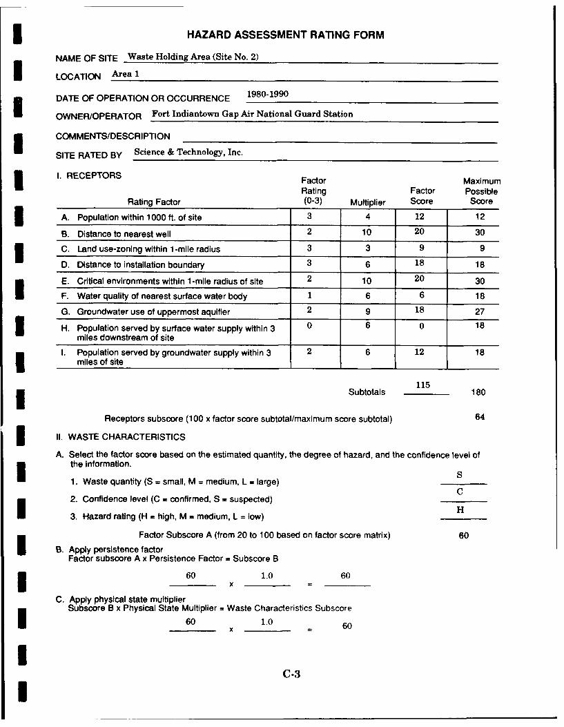
3 HAZARD ASSESSMENT RATING FORM
NAME OF SITE Waste Holding Area (Site No. 2)
I LOCATION Area 1
DATE OF OPERATION OR OCCURRENCE 1980-1990
OWNER/OPERATOR Fort Indiantown Gap Air National Guard Station
I COMMENTS/DESCRIPTION
SITE RATED BY Science & Technology, Inc.
3 I. RECEPTORS Factor MaximumRating Factor Possible
Rating Factor (0-3) Multiplier Score Score
3 A. Population within 1000 ft. of site 3 4 12 12
B. Distance to nearest well 2 10 20 30
C. Land use-zoning within 1-mile radius 3 3 9 9
D. Distance to installation boundary 3 6 18 18
E. Critical environments within 1-mile radius of site 2 10 20 30
F. Water quality of nearest surface water body 1 6 6 18
G. Groundwater use of uppermost aquifier 2 9 18 27
3 H. Population served by surface water supply within 3 0 6 0 18miles downstream of site
I. Population served by groundwater supply within 3 2 6 12 18miles of site
115Subtotals 180
Receptors subscore (100 x factor score subtotal/maximum score subtotal) 64
I II. WASTE CHARACTERISTICS
A. Select the factor score based on the estimated quantity, the degree of hazard, and the confidence level ofthe information.
1. Waste quantity (S = small, M = medium, L = large) SC
2. Confidence level (C = confirmed, S = suspected) C
3. Hazard rating (H = high, M = medium, L = low) H
Factor Subscore A (from 20 to 100 based on factor score matrix) 60
I B. Apply persistence factorFactor subscore A x Persistence Factor = Subscore B
60 1.0 60I xC. Apply physical state multiplier
Subscore B x Physical State Multiplier = Waste Characteristics Subscore
60 1.0 60
IC-3I
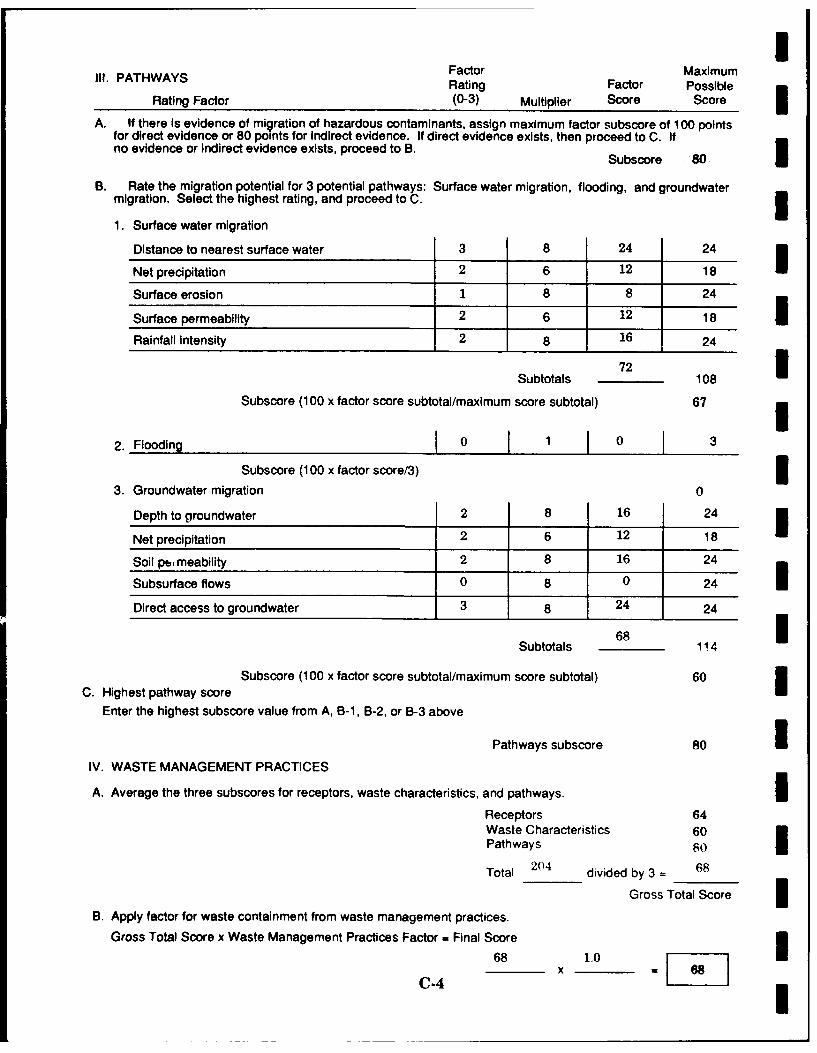
IIll. PATHWAYS Factor Maximum
Rating Factor PossibleRating Factor (0-3) Multiplier Score Score I
A. If there Is evidence of migration of hazardous contaminants, assign maximum factor subscore of 100 pointsfor direct evidence or 80 points for Indirect evidence. If direct evidence exists, then proceed to C. Ifno evidence or indirect evidence exists, proceed to B. 8
Subscore 80
B. Rate the migration potential for 3 potential pathways: Surface water migration, flooding, and groundwatermigration. Select the highest rating, and proceed to C. 31. Surface water migration
Distance to nearest surface water 3 8 24 24
Net precipitation 2 6 12 18
Surface erosion 1 8 8 24
Surface permeability 2 6 12 18 3Rainfall intensity 2 8 16 24
Subtotals 108
Subscore (100 x factor score subtotal/maximum score subtotal) 67
2. Flooding 10 1 0 3
Subscore (100 x factor score/3) 33. Groundwater migration 0
Depth to groundwater 2 8 16 24
Net precipitation 2 6 12 18
Soil pb, meability 2 8 16 24
Subsurface flows 0 8 0 24 iDirect access to groundwater 3 8 24 24
Subtotals 6 114
Subscore (100 x factor score subtotal/maximum score subtotal) 60C. Highest pathway score
Enter the highest subscore value from A, B-1, B-2, or B-3 above
Pathways subscore 80 iIV. WASTE MANAGEMENT PRACTICES
A. Average the three subscores for receptors, waste characteristics, and pathways. IReceptors 64Waste Characteristics 60Pathways so ITotal 204 divided by 3 68
Gross Total Score i
B. Apply factor for waste containment from waste management practices.
Gross Total Score x Waste Management Practices Factor - Final Score i68 1.0
C-4I

HAZARD ASSESSMENT RATING FORM
NAME OF SITE Old Waste Holding Area (Site No. 3)
LOCATION Area 2
DATE OF OPERATION OR OCCURRENCE 1975-1986
OWNER/OPERATOR Fort Indiantown Gap Air National Guard Station
I COMMENTS/DESCRIPTION
SITE RATED BY Science & Technology, Inc.
3. RECEPTORS Factor Maximum
Rating Factor PossibleRating Factor (0-3) Multiplier Score Score
A. Population within 1000 ft. of site 3 4 12 12
B. Distance to nearest well 3 10 30 30
C. Land use-zoning within 1-mile radius 3 3 9 9
D. Distance to Installation boundary 3 6 18 18
E. Critical environments within 1-mile radius of site 2 10 20 30
F. Water quality of nearest surface water body 1 6 6 18
G. Groundwater use of uppermost aquifier 2 9 18 27H. Population served by surface water supply within 3 0 6 0 18
miles downstream of site
I. Population served by groundwater supply within 3 2 6 12 18miles of site
125Subtotals 180
Receptors subscore (100 x factor score subtotal/maximum score subtotal) 69
I II. WASTE CHARACTERISTICS
A. Select the factor score based on the estimated quantity, the degree of hazard, and the confidence level ofthe Information.
1. Waste quantity (S = small, M = medium, L = large)C
2. Confidence level (C = confirmed, S = suspected)
3. Hazard rating (H = high, M . medium, L = low)
Factor Subscore A (from 20 to 100 based on factor score matrix) 60
I B. Apply persistence factorFactor subscore A x Persistence Factor = Subscore B
60 0.9 54
C. Apply physical state multiplierSubscore B x Physical State Multiplier = Waste Characteristics Subscore
54 x 1.0 = 54
C-5I

Ill. PATHWAYS Factor MaximumRating Factor Possible
Rating Factor (0-3) Multiplier Score Score
A. If there Is evidence of migration of hazardous contaminants, assign maximum factor subscore of 100 pointsfor direct evidence or 80 points for Indirect evidence. If direct evidence exists, then proceed to C. Ino evidence or Indirect evidence exists, proceed to B. Subscore 0 3
B. Rate the migration potential for 3 potential pathways: Surface water migration, flooding, and groundwatermigration. Select the highest rating, and proceed to C. I1. Surface water migration
Distance to nearest surface water 2 8 16 24
Net precipitation 2 6 12 18 3Surface erosion 1 8 8 24
Surface permeability 2 6 12 18
Rainfall intensity 2 8 16 24
Subtotals 108
Subsore (100 x factor score subtotal/maximum score subtotal) 59
2.Fodn o 1 0 ISubscore (100 x factor score/3)
3. Groundwater migration 0
Depth to groundwater 2 8 16 24
Net precipitation 2 6 12 18
Soil permeability 2 8 16 24
Subsurface flows 0 8 0 24
Direct access to groundwater 3 8 24 24
Subtotals 114
Subscore (100 x factor score subtotal/maximum score subtotal) 60C. Highest pathway score
Enter the highest subscore value from A, B-1, B-2, or B-3 above
Pathways subscore 60
IV. WASTE MANAGEMENT PRACTICES
A. Average the three subscores for receptors, waste characteristics, and pathways.
Receptors 69Waste Characteristics 54Pathways 60
Total 183 divided by 3 = 61Gross Total Score 3
B. Apply factor for waste containment from waste management practices.
Gross Total Score x Waste Management Practices Factor = Final Score
61 1.0
C-6

I
I Fort Indiantown Gap Air National Guard StationAnnville, Pennsylvania
USAF Hazard Assessment Rating MethodologyFactor Rating Criteria
E The following is an explanation of the HARM factor rating criteria for the threepotential sites identified at the Station:
I. Receptors
3 A. Population Within 1000 feet of Site.
Site Nos. 1-3, Factor Rating 3. The weekend population within 1000feet of Site Nos. 1 and 3 is approximately 300 persons on UnitTraining Assembly (UTA) weekends. The population within 1000 feetof Site No. 2 is 260 persons on weekends.
I B. Distance to Nearest Well.
Site Nos. 1 and 3 have Factor Ratings of 3. They are located 900 feetand 800 feet, respectively, from the nearest water well. Site No. 2has a Factor Rating of 2 because it is located 3300 feet from the
I nearest water well.
C. Land Uqe-Zoning (within 1-mile radius).
I Site Nos. 1-3, Factor Rating 3. The Fort Indiantown Gap MilitaryReservation is not officially zoned by local civilian authorities.However, there are private residences within the 1-mile radius andmilitary personnel are billeted on the reservation.
D. Distance to Installation Boundary.
Site Nos. 1-3, Factor Rating 3. Site No. 1 is 75 feet from theinstallation boundary. Site No. 2 is 275 feet from the bour.dary, andSite No. 3 is 150 feet from it.
E. Critical Environments (within 1-mile radius).
Site Nos. 1-3, Factor Rating 2. Small wetland areas are locatedwithin a 1-mile radius of each site.
II
C-7
II

II
F. Water Quality/Use Designation of Nearest Surface Water Body.
Site Nos. 1-3, Factor Rating 1. Qureg Run and its unnamed tributary Iare classified as warm water fisheries.
G. Groundwater Use of Uppermost Aquifer. ISite Nos. 1-3, Factor Rating 2. The uppermost aquifer is used as asource of drinking water, but municipal water from surface watersources is available at certain locations in the area.
H. Population Served by Surface Water Supplies Within 3 Miles IDownstream of Site.
Site Nos. 1-3, Factor Rating 0. No one in the area is served by 3surface water supplies obtained within 3 miles downstream of thesesites.
I. Population Served by Aquifer Supplies Within 3 Miles of Site.
Site Nos. 1-3, Factor Rating 2. Based on a count of 197 wells within 3a 3-mile radius of the Station, given the assumption that most ofthese are household wells and that there are 3.8 individuals perhousehold, it is very broadly estimated that approximately 750 peoplereceive water from aquifer supplies.
II. Waste Characteristics 1Site No. 1
A-i: Hazardous Waste Quantity - Factor Rating M (Moderate). Asmany as 1320 gallons of mixed waste oil, brake fluid, dieselfuel, paint thinner, PD-680 solvent, and trichloroethane mayhave been disposed of at this site.
A-2: Confidence Level - Factor Rating C (Confirmed). This site was Iconfirmed through interviews with Station personnel.
A-3: Hazard Rating - Factor Rating H (High). This site was givena high hazard rating because of the high toxicity of manypetroleum products.
IC-8 I
I
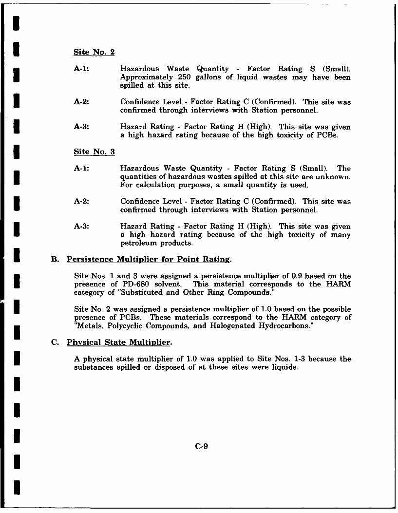
I
I Site No. 2
A-1: Hazardous Waste Quantity - Factor Rating S (Small).Approximately 250 gallons of liquid wastes may have beenspilled at this site.
A-2: Confidence Level - Factor Rating C (Confirmed). This site wasconfirmed through interviews with Station personnel.
3 A-3: Hazard Rating - Factor Rating H (High). This site was givena high hazard rating because of the high toxicity of PCBs.
Site No. 3
A-1: Hazardous Waste Quantity - Factor Rating S (Small). Thequantities of hazardous wastes spilled at this site are unknown.For calculation purposes, a small quantity is used.
A-2: Confidence Level - Factor Rating C (Confirmed). This site wasconfirmed through interviews with Station personnel.
A-3: Hazard Rating - Factor Rating H (High). This site was givena high hazard rating because of the high toxicity of manypetroleum products.
I B. Persistence Multiplier for Point Rating.
Site Nos. 1 and 3 were assigned a persistence multiplier of 0.9 based on thepresence of PD-680 solvent. This material corresponds to the HARMcategory of "Substituted and Other Ring Compounds."
I Site No. 2 was assigned a persistence multiplier of 1.0 based on the possiblepresence of PCBs. These materials correspond to the HARM category oft"Metals, Polycyclic Compounds, and Halogenated Hydrocarbons."
C. Physical State Multiplier.
A physical state multiplier of 1.0 was applied to Site Nos. 1-3 because thesubstances spilled or disposed of at these sites were liquids.
III
C-9
II

I
III. Pathways Category IAL Evidence of Contamination.
Site Nos. 1 and 3 were given a Factor Rating of 0. No oil stainingor other evidence of contamination is visible at these sites. Site No.2 was given a score of 80 (Indirect Evidence) because it is greatlysuspected of being a source of contamination. Heavy oil staining iscurrently observable at the site.
B-1. Potential for Surface Water Contamination.
0 Distance to Nearest Surface Water: Factor Rating 3 for SiteNos. 1 and 2. These sites are located within 500 feet of stormsewer lines. Site No. 3 was given a Factor Rating 2. It islocated approximately 800 feet from an unnamed tributary of IQureg Run, which receives sheet drainage from the site.
0 Net Precipitation: Factor Rating 2. The average annual net 3precipitation for Site Nos. 1-3 is 14 inches.
0 Surface Erosion: Factor Rating 1. Surface erosion is slight atSite Nos. 1-3.
o Surface Permeability: Factor Rating 2. The surfacepermeability at Site Nos. 1-3 is 4.24 x 10' to 4.24 x 10' cm/sec.
o Rainfall Intensity Based on 1-Year, 24-Hour Rainfall: FactorRating 2. The rainfall intensity at Site Nos. 1-3 is 2.5 inches.
B-2. Potential for Flooding.
Factor Rating 0. Site Nos. 1-3 are located beyond the 100-year floodplains of local streams.
B-3. Potential for Groundwater Contamination.
o Depth to Groundwater: Factor Rating 2. The depth to 3groundwater at Site Nos. 1-3 is 15 to 20 feet.
o Net Precipitation: Factor Rating 2. The average annual netprecipitation for Site Nos. 1-3 is 14 inches.
o Soil Permeability: Factor Rating 2. The soil permeability forSite Nos. 1-3 is 4.24 x 10' to 4.24 x 10' cm/sec.
1C-10
II

I
0 Subsurface Flows: Factor Rating 0. The bottoms of Site Nos.1-3 are greater than 5 feet above high groundwater level.
o Direct Access to Groundwater: Factor Rating 3. Because of theextensive structural deformation of the area, fracturing of thebedrock beneath Site Nos. 1-3 is probable.
IV. Waste Management Practices Factor
Since there is no containment at Site Nos. 1-3, a multiplier of 1.9 is used.
[I[IIIII[III C-I1
II