ii - defense technical information center · _ 4 j ;-ý: .7r ' - " taw suwelass=1fe.....
TRANSCRIPT

AD-768 389
AIR CARGO RESTRAINT CRITE'RIA
Joseph L. Weingarten, et al
Aeronautical Systems DivisionWright-Patterson Air Force Base, Ohio
April 1973
Ii
DISTRIBUTED BY
-~iu To Ill IService
U. S. I OF COMME1RCEill IIIIII
525Pr oalRaofnfil a 25
NOTICE ,
When Government drawings, specifications, or other data are used for any purposes I.other than In connection with a definitely related Government procurement operation, Athe United States Government thereby incurs no responsibility nor any obligationwhatsoever; and the fact that the government may have form-•uated, furnished, or inany way supplied the said drawings, specifications, or othe-: data, is not to be reg.ardedby implication or otherwise as in any manner licensJng the holder or any other personor corporation, or conveying any rights or permisslorn to manwlacture, use, or sell anypatented Invention that ma In any way be related the:7efo.
.L.
13
Copies of this report should not be returned unless return is required by securityconsiderations, contractual obligations, or notico on a specific document.
AIR FORCE/56780/25 Jun. 1973 - 400
" ' -• I
-• ,AJ

ASD-TR-73-17
FINAL REPORT-AIR CARGO RESTRAINT CRITERIA
JOSEP11 L. WEINGARTEN
CHARLES P. MA YRAND
GEORGE E. MULLER
7
A
Approved for public relvaso; distribution uriimitcd.
*1
I N
9

ASD-TR-73-17
FORE°RD
This report -was D,-epared jointly by the Deputy for Engineering, '-{ •
Aeronautical System Divipion (ASD), and the Air Force Flight Dynamics
Laboratory (AF-OL), Air Force System Command, Wright-Pa+tterson Air Force
Base, Ohio. ?i-- initial work effort was accomplished under AFFDL project 4 •
136'i, "Structural Design Criteria for Military Aerospace Vehicles," and
Task 136702, "Aerospace Vehicle Airframe Design Criteria." This effort
resulted in AFFDL-TP-7!-l39, "Air Cargo Restraint Criteria" which has been
abridged a id incorporated in this report as Appendix 1. The abridgme~nt
relates only to specific aircraft accidents and dates which have been
deleted.
This report was accomplished under ASD Project USAD 0034, Air Cargo
Restraint Criteria.
Tians document has been reviewed and is approved.
4'-
PAUL E. BE(* G. IL NEGAARD., Major., USAFTec~hnical Director Chief, Design Criteria BranchCrew and AGE Engineering Structures DivisionDeputy for Engineerign Air Force Flight Dynamics
Laboratory
A43
iiA

_ 4 -ý: .7r ' - " j ;
tAW
SUWELASS=1FE.. DOCUMENT COHTROL DATA P-4 " D
fucaudey ci aeuinkatio of title. bd feaisctai end tIndoxing atniitmtion mus t b wwid N1~n-iA. toweta t 14~ C1808114:2d .
I GIATI~.ACIVI~ (COpC~. aulwejtie REPORT? 1CCU~fThY C "ASL2FICA1ION
I.-puty 'f Bgneri 3. S, or UNCIASSIIED'_______A.", Force Flight Dynamics Laboratory, b. GROUP
Wr j.ghtPatterson AFB,, Ohio 1h5h33 -
3 CVOPIT. TITLE
1.nal Report - Air Cargo Restraint Criteria
4. OC*C*I0 riVf NOTCS (7),p* of repw and Inclutiv. dates) "
te - ATmOvitsi(fliaba hmi.a.ddle Initi0t. lalt tn283)J6se.•"h-L. Weingarten,-. Charles V. Mx-and,
.eorge E. FOlrEPOf•T oATE 741. TOTAL NO. Or PAGES or NO. OE OCFS
nAri- 1973- 16 __W".-ONWfACT-OW. GNANTN.g.mPFrNtoIZ
b. P,,CU'T NO. USAPFý3h ASD-TR-73-17
C. Sb. OT14VR REPORT NOIS) (Ant othernrJmbbte 8h&tI M. ••e•*i•dW~e tepot)
IOISTROIUTION STAT&MIC"T
Approved for public rziease; distribution unlizrkted
11. `&INTAIR Nyr9TsIo 1. 2. 1IPON1IOR.'tG UAILITARY ACTIVITY
-'-.-. -.I.,,Deputy for -igineering, ASD, or -
/EN ST~liFOg //-Air Force Flight Dtnamics Laboratory,IS- &USD/ENCT SI Wright-Patterson AFB, Ohio 45433
[ -'A major change in Air Force air cargo restraint criteria has been enacted. Therevised criteria, which are based on techni,Ial report AFFDL-TR-71-139, Air CargoRestraint Criteria, and their inplementation are presented. An extract o- AFFDL-TR-71-139 is included as Appendix I.,
T7he initial invest'gation was conducted to determine probabilities of encounter-
ing various forrard crash load factors; to determine if cargo restraint procedures 4could be improved for better operational capability. Safety and cost factors wereviewed in relation to curtent air transportability requirements.
In determining the probabiii'ties, data from January 1960 to July 1971, coveringall *major USAF cargo aircraft accidents with a totar flying time in excess of 31
• • million hours, was used.
The results showed that the risk to passengers on cargo flight is statisticall)rare and that a change in air car.go restraint procedures would provide a safer syste,than previously available with an overall cost savings to the military services.,r Re,todu•cecby
NATIONAL TECHNICAL.INFORMATION SERVICE
U S otprttment of cotneo.rceSpai-ngeWd VA 22151
FOR14I *DD -NOV J4713- UNCLASSIFIEDI ~-' sec~uity Mlssiiicati..
S/
4, . L .? -. •.-~-' •• • ' • '• " . .

J1
- Security C.18SWIAif tio'l 71A
KEY WORDS Llm* A LANK 0 LINK C
RD~L Wr mPtxL wT AROIL "T
Aircraft cargo restraint
Air transpcrr, restraint
Air cargo restraint criteria
Air transportability criteria
Equipment desi-gn 8- tra•nsport
Crash data anarysis
B*u..oeipw ent Prsinig ottir tr7an Sport ,7 ecrt casnct
4.-•
-- k-r
:14
kU.S.Gover,..nent Prinking Off|€e: 1973-- I5m4min7 L }•i]... ; 4T' -• -
Ba

4 ASD.-TR-73-17
ABSTRACT
A major change in Air Force air cargo restraint criteria has been i
enacted. The revised cr.teria, which are based on technical report I
AFFDL-TR-71-139, Air Cargo Restraint Criteria, and their imnlementation
are presented. An extract of AFFDL-TR-71-139 is included as Appendix 1.
The initial investigation was conducted to determine plobabilities of
encountering various forward crash load factors; to determine if cargo
restraint procedures could be improved for better operational capability.
Safety and cost factors Were viewed in.relationto current air transport-
ability requiremefits.
In determining the probabilities, data from January 1960 to July 1971,
covering all major USAF cargo aircraft accidents with a total flying tizwe
in excess of 31 :iillion hours, was used,
The results showed that the risk to passengers on cargo flight is
statistically rare and that a change in air cargo restraint procedures
would provide a safer system than previously available with an overall
cost savings to the military services.
'-4

A3D-TR-73- 17
TABLE OF CONTENTS
SECTION PAGE
T INTRODUCTION
SIi IMPACT
1. Air Force Operations 3
2. Aircraft Desigr
3. Equipment Design 5 !i
4. 463L Equipmrnt 6
5. Cost Savings 6SIl SUJMM4ARY
i PFENDIXAFFDL-TR-71-139, AIR C•ARGO REsTrpAINT CRITERIA!:::: • -12
4
44L

k AS 4R-7 -17ILLUSTRATIONS
FI GUR E PAGE
1 Con-nercial Barrier Net9
2 lan Zelmi ?Ret 10
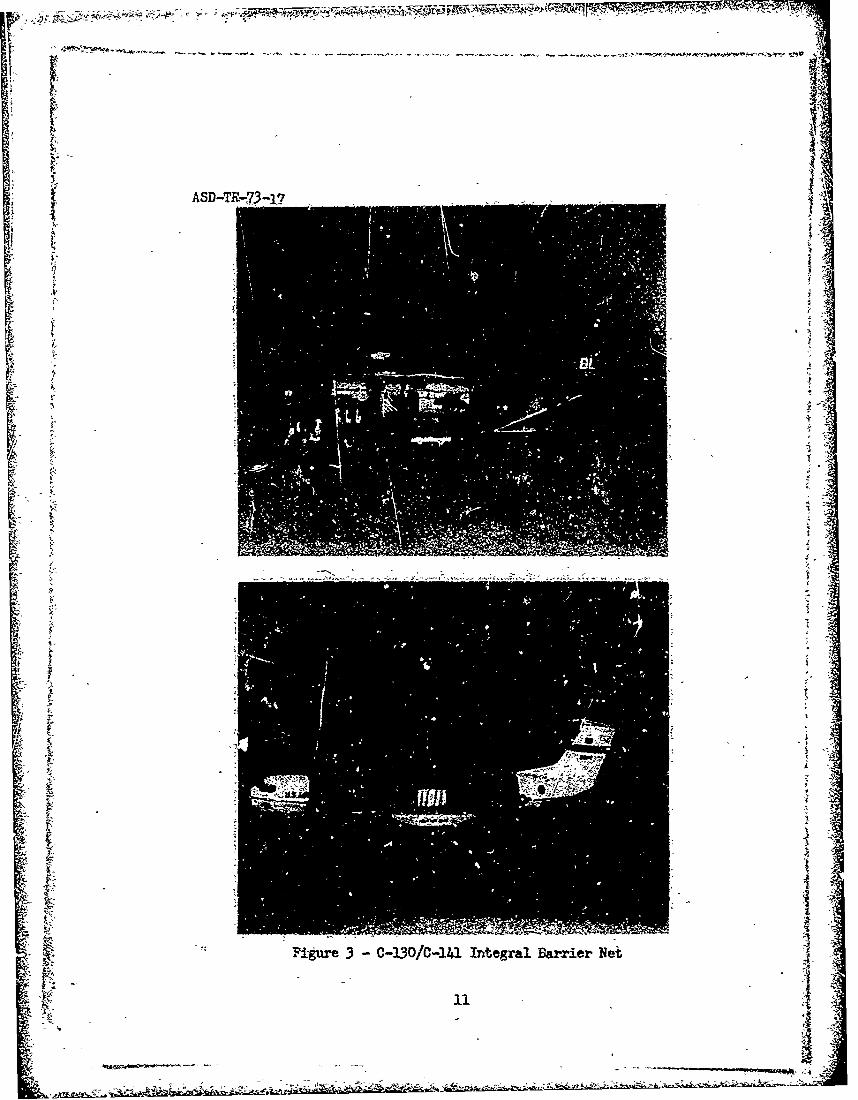
3 0-130/ 0,-141 Integral Barrier Net 1
z
iM
#1 -,

W .... TM7W. -!-
ASD-TR-73-17
F- SECTION I
1N9'RODUCTION
AFFDL Technical Report 71-139, "A:r Cargo Restraint Criteria," was
published for Air Force use in January 1973. Th. report has been
abridged to allow its reproduction as Appendix I by deleting specific
%ircraft accident data and related dates. The removal of the accident
data does not affect the presentation or conclusions of the report.
TheThe report recor±.mended a revision to Air Force restraint criteria.
The then current aircraft cargo handling systems and cargo designated
air transportable are built to a 9G forward loading capability to with- , I
stand crash loads. The proposed changes would require that air trans-
portable euaipement and aircraft cargo handling systems be designed to an
operational 3G forward load and that aircraft barrier nets be utilized
to provide a 9G forward capability for personnel protection. This chamnge
in restraint technique would lower equipment costs and provide a safer
overall system. Nuclear cargo movement was not examined in the initial
worY. effort; current transportability requi.r-ements for nuclear cargo will
be ,mAintained pending'a full review of the area.
The adoption of the recommunended cargo restraint revisions by the Air
C-' Force in December 1972 resulted in the approval of the following actions:
a. The operational X.- requirement for cargo tie-down without passengers
seated forward of general cargo will be lowered to 3G. Nuclear cargo will
continue to -be restrained to its currnnt 4G level.
'•' I1

II
b. Air Force Systems Command will investigate impi-oved/alternative
methods of nuclear cargo transport.
c. Passengers or nuclear cargo carried forward of general cargo
will be protected by a barrier net positioned in front of the general tcargo. Nets will be positioned to achieve a minimum 8G forward restraint
tor t the structural limitations-of the fuselage, whichever is greater.
d. An investigation will be conducted by ASD to determine the
easibility of installing an integra, barrier net in the C-130 and C-141
ircraft. The restraint capability to be provided will equal the
structural limitations of the fuselage.
e. Specification 1L4L-A-008865A, "Airplane Strength and Rigidity
Miscellaneous Loads," will be revised to establish a 3G cargo restraint
system in conjunct-ion with a 9G auxiliary net ?estraint system to be used'
when passengers are seated for.ard of cargo on the same deck level.
f. Specification MIL-A-821, "General Specification for Air Trans-
"portabbility Reqairements, " will be revised by deleting the 9G crash load
requirements. Action will be initiated to coordinate the revised
specification with all services.
g. A program will be established to define the addition~l data
required of Air Force cargo aircraft accident investigations alplicable
to the development of criteria relating to airframe crash worthiness,
cargo restraint, seat design, and personnel survivability.
2,i~ "

, o , -- -'
-i
ASD-TR-73-17i'-SECTION 11
T3nPACT
The implementation of the approved actions presented in Section I-
"will have a far ranging influence on future Air Force operations,
aircraft design, and equi.inent design.
"1. Air Force Operations - Cargo movement will be simplified by
V perndtting all general cargo to be secured to a 3G restraint level. -
"Previously, several different G factors were allowed (Table I and II,
Appendix 1) depending on the aircraft and its cargo/passenger con-
figuration f a particular mission. Although variab2e factors were
allowed, standard practice required that pallet loads be restrained to
the axium equred estain leel;the aircraft to be u.-ti'lized
initially, aircraf t changes in route, and cargo/passenger corfigurations.p:
are not only variable b-t often unknown at the time that a pallet iis
loaded, in conjunction with the 3G pallet restraint, the Van Zelni riett.
(shovwn in Figure 1) wq.ll be required on flights wnhere passengers or
nuclear cargo are placed forward of the general cargo to provide a
w-nimmnun 8G level of restraint. The Van ZeLm nets are currently available
and being used by the operational Comnmands. The net does, however, requi re
additional effcrt to install and readjustanents prior to each flight. The
" additional cargo loading complexity does somewhat affect the advantages
t of using a 3G pallet restraint but this w0ll be a: tempcraily disadvantage.
3
____ ____ ____ ___ ___ - - - ~ -- in

44
ASD-TR-73-17
An integral barrier net restraint system and related installation
requirements for C-130 and C-141 aircraft have recently evolved from an "
Air Force preliminary design study. This barrier net system is intended to
Ao vercome the using co,-rands' objections to the complexity of the Van gelm 4"
net and the restricted movements imposed by the cormercial (see Figure 2)
barrier net system. The new net system provides installation flexibility
and allows inflight movement of persornnel along the length of the cargo
compartment. The prctotype concept provides the necessary flexibility
through A ceiling suspension trolley system which allows the net to be
-Opositioned at any point within the cargo compartment. Its restraint is
provided in a manner similar to that of the Van Zelm net, which ties -
directly to existing floor rings. The ceiling supports dc not provide 9
restraint (see Figure 3); however, the ceiling suspension system does
insure that the net will appropriately envelope the cargo should it
exceed its 3G restraint level and move forwarxi during crash impact.
Aerial delivery loads are also affected and have been reduced from 4G to
30. -'
2. Aircraft Design -,Amendments issued to MIL-A-O08865A will provide
future cargo aircraft with.a 3G (2.0G x l.5F.S.) forward- cargo restraint
system to react the low G operational contingencies of en emergency-
nature in conjunction-with an integral barrier net. ystem providing an
overall 9G level of protection for passengers when circumstances warrant.
A-4I * I---
ASD-TR-73-17 • 4
SA measure of the impact that this new concept will have can be e
I obtained by comparing the results of a study conducted by the Mc-Dornell--
S~Douglas Corporation for -the Deputy for Advanced Plarming, Aeronautical .
[ Systems Division. The analysis considered the cost and-weight variations ' :
g" • ~for a medium STIOL type airplane incorporating the above 3G/9G system and • .
Sa conventional. 9 cargd-restraint system. The study showed a potential .
•:£ --st reduttion of 1.2 percent and- an empty weight reduction Of 1.6 percent•! • for each aircraft,. Considering th w eimSO i ae ur-rent1_y : •
being procured under the.prototype concert at a projected rost of five :
!ii
million dollars each the cost savings on a production bui of 200 air-
dobar savings wouldp also be obtained over the life of the airpanesll
through the impraived operational efficiencies thai would result from n at
Sytmslower airframe neight."'3. E ea Design. - The potential for cost savings is greatest in the
area of aur transportable equibn ent design. Each military service hasequirment designated air transoortable and is goveried by a coton design
specification, KIL-P.- 8421, "Air Transportabilit Re-quirements."1 Thisequipmaent includes, for example, most cmbat groufi vehicles ustdby eache
service, Air Force ACGE, containers and vans,, artillery pieces, mobileI bridges and related Corps of Engineering equiprent. Air Force Bare Base A
.equipment requirema'its are even more extensive in scope. This conceit -
considers only a cleared land area of sufficient size to support tactical
li
5~

ASD-TR-73-- 1-7
aircraft operations, without physical facilitias or natural resources
other than a usable runway, taxiways, prarking area; and a source of 3
water. These basic resources are then transferred to an operational •
STactical Air Force Base in a matter of days. All equipment is flown
in, including outsized equipment, and all of it is designated air
transportable. Previously, vehicles and equipment considered air
transportable had to remain intact following a 9G forward load and
operate follciwing a 3G forward load. The removal of the 9G load factor
design requirement will not affect current equipment inventories but will
have a-signi .?icant effect on all future procurements.
.uture pallet and net procurements for the i:63L
s~ystems will be directly affected by the lower restraint requirements.
The reduction in allowable strength will permit the use of lighter nets
and tis-drnrr rings on the palets and extruded rails in pallet construction.
5. Cost Savings - •The cost, savings to be accrued b~y the reduced restraint •
requirement for general and aerial delivery cargo cannot be estimated as
accurately for air transportable equipment, cargo handling equipment, or
changes in operational procedures as they csh for the previously cited
airplane design example. Many v-riables zrast be considered in addition
to the overall scope of the operation. YMny influences, although smali,
are very significznt when the total number of repetitious events isA
considered. Hence, the increased rapidity of loading permitted by a re-
duction in total restraint, the 'reduction in required tie-down equi'mrnt
I,~.

ASD-TR-73- 17
and related weights savings, the associated savings in manpower, man-hour
reductions in equipment design and testing, lower manurfacturirg costs and
improved cargo airplane turn-around times, will all contribute to theS• significant savings anticipated as a result of the restraint reduction
for cargo. In addition, greater protection will be afforded passengers• • on vixed cargo/passenger flights as diecussed in Sections Vand VI of the
S~Appendix. .
V
ff
r
k• -:I
7:
.?: , •

ASD-TR-73- 17•4
SECTION III
SUMMARYr
Actions taken within the Air Force will provide, upon complete
implementati.n, a cargo restraint system that is safer than the one
currently in use. The most significant safety improvement will be the
design and installation of an integral barrier net system in the C-130
and'C-141 aircraft. -•
Considerable cost savings will accrue in all military services as
new equipment is designed. The Air Force will also benefit from
simplified procedures in tieing down both cargo and airdrop loads.
PFuture aircraft will be lighter in weight, resulting in a cost savings
when procured and throughout its lifetime.
The previously discussed changes in air cargo restraint requirements
vere based on a study of data from USAF cargo aircraft accidents over a
ten year period. It was apparent during the study that additional data
could be included in the accident reports which would be valuable in
developing future cargo and personnel restraint system criteria. Under-
standably, current accident report requirements concentrate on the causes
of accidents and recomnendations for actions to prevent recurrence.
Mirdzanm detailed data is included on what happened to seat, cargo, fuel,
and' other items on the aircraft durirg the crash. Procedures are being
developed to obtain additional data from accidents which can be used to
Simprove design requirements and emergency procedures to enhance personnel
survivability in the aircraft crash environment.
4 A• • 8

I- fvI
ASD-TR-73-17
t" Cargo
S AMER NET
S~~Steel "":. Cable
.' Tubular
-• A ,,•"•.:RA.K•x." LOCKS
ITicedown B1~//
NNI I
Sr
Figure 1 - Commercial Barrier Net
11111Iwl

IT
I, I
caI- LII zI1.e
100
ASD-TR-n73-1?
1w~
t.~~~~~~~~~~ 4.t r - 3 / - 4 I t g a a x e e

AFFDL-TR-7)-139 APPENDIX
SECTMON I
INTROCUCTiON
I. COPE
-This investigation examined the load factor criteria used in air-
cargo-restraint system design and operation in light of the latest Air
Force cargo aircraft accident data and available information on the
acceleration environment encountered in cargo aircraft crashes, The
objectives were to: (I) develop the probabilities of encountering various
magnitudes of load factors, and (2) assess the potential of oersonnel
injury associated with designing and operating cargo restraint systems
at different load factor levels. The results are intended'to be used
as a guide in making decisions on the levels of restraint that will be
required in fucure air cargo operations and equipment design.
The currently published USAF load factor requirements related to
the air cargo restraint system are sumnarized in Table I. -Note that -
these criteria are specifically applicable to: (1) the -Irframe
attachments with associated carry-through structure, and (2) any
equIpment which is to be air transported. The link between the airfrre
and the transported equipment is the tie-down equipment and the procedure 31
is to m•ke the strength of this link equivalent to the load requirements
shown in Table I.
-_The application of the load'factors shown'in Table I, as wall as
those required by previous editions of the noted specifications, has a'
significant impact on the design and use of air cargo handling equipnxent.
124-A

AFFDL-TR-71-139
The validity of tht magnitudes of the load factors has frequently been
questioned and was one of the reasons for Initiating this study.
Table 18 permits comparison of current load factor requirements
(Table I) with the load factors used to design airframe attachments and
basic cargo handling systems for the primary ai:ecraft in the USAF cargo
transport fleet.
2. BACKGROUN b
As previously noted, the load- factor criteria used to design restraint•=::!" systems for cargo being transported by military aircraft has a significant '•
effect on flight safety, cargo aircraft and cargo handling equipment A
design, and the eFfectiveness of air cargo operations. The primary
factors affected are the safety of the aircrews and passengers; the
weight, cosL, and complexity of the basic airframe, and the cargo handling
4
Advances in air cargo handling equipment and procedures such as the
palletized cargo system,and, more recently, the proposed use of airlift
containers has focused additional attention o6 the need for realistic
air cargo restraint criteria. These criteria must include the loads
resulting from tht accelerations which c€jn be encountered during, all
phases of the air,'cargo transport mission. The accelerations associated
with normal takeoffs, aIr turbulence, maneuvers, and landings ,re
predictable and pose no serious problem3. It is the least predictable
emergency situation or, more specifically, the acceleration environment

-AOFDL-TR-71-139
encountered in aircraft accidents, which Is tie key to air-trgo restraint
criteria. Cargo aircraft accidents ranging from hard landings to
catastrophic crashes provide the data base from which the limits for
the load factors specified in air cargo restraint criteria must be
developed.
It should be remembered that the load factors associated with the
crash acceleration environment (regardless of whether the criteria
applies to restraint of cargo, personnel, or miscellaneous equipment)
are essentially empirical values based on past experience and supported
only by a limited amount of full sc.z:e aircraft crash test results.
The prime factor in determining the limits for air cargo restraint is
personnel safety. This is reflected in the higher Ic.3d factors currently
required (reference Table I) when there is a potential of Injury to
the arcraft crew-and/or passengers.
3, OPERATIONAL CONSIDERATIONS
Three aircraft systems ae of primpry concern. These are C-130,
C-141, and C-5. The current forward restraint load factors vary as 3
show, helow:
Current Re•traint Load Factors
Aircraft Oper3tional Cargo/Pax ix-Cargo Only
C-130 4 8 aor
C-141 4 937
*Pas~tngers~ar-, se~ated above the cargo compartme*nts.
144

FRISAFFDL-TR-71-139
-a'
The viriation In load factors between aircraft types has caused
concern in two aee.s. First, transfer of one load from one air vehi.le
to another may require additional restraint. Secondly, many items
carried on aircraft cannot be restrained to the 8 and 9 load factor
level. For example, a US Army 2-1/2 ton truck'weighs 19,785 pounds.
Even when secured by a 9-G restraint system, the attachment points on
the vehicle will faiT at 6 G's forward. The effective strength of the
fittings are further reduced to 4.5 G's when the downward components of
the restraint, tie-dowkts are introduced (Reference 1). The battery,
p. - windshreld, and other components of the truck will begin to separate
from the body and frame to become lethal missiles at approximately. 2 GIs
forward. Similarly, the new air-land-sea container, which is expected
to enter the air cargo system in the near future, cannot be directly
restrained to 9-G levels without an auxiliary restraint system. Container
restraint is a matter of concern and one of the factors which established
this study.
4. APPROACH
The limited time neriod scheduled to accomplish this investigation
required the application of readily available data pertinent to the
problem area. Two primary sources of data were used. The first was
Air Force cargo aircraft operational data with special emphasis on
cargo aircraft accident information for che period from Janu3ry 1960 to
N -1July 1-971. The results of the analysis of this data are presented in
Section 11.
I 2y1>ý Al I

AFFOL-TP-71 -139
The second source of data is analyses which have been conducted of ~-
transport aircraft accidents and full scale aircraft crash tests to,
define the crash acceleration environrmnt. The application of theset
data Is discussed in Section ill.
?
16
AFFDL-TR-7l-139
SECTION I1
AIRCRAFT ACCIDENT AtMLYSIS AND PREDiCTIONS
An aircraft accident can be termed an unlikely event; yet, through
analysis of past accident history, predictions can be made of the
occurrence of an accident and related events.
S~1. DATA REFERENCEThree sets of Interrelated data were used in this study to formulate
the probabilities -f an accident and its relation to cargo transport.
The Deputy Inspectur General for Inspection and Safety, USAF, Norton
Air Force Base, California (IGDS), maintains records and published
reports on all Air Force aircraft accidents. The documents utilized
were US Air Force Accident Bulletins from 1960 through 1969, which
provided overall statistical -data on all accidents. To obtain additional
decailed accident data, a request was submitted to IGDS and they applied
the computerized accident data system to provide informn~tion on all
(415 cases) major cargo accidents from January 1962 to July 1971. This
provided data on the cause of accident, phase of operation, and personnel
injuries for each aircraft. To provide details that were not available
in the accident bulletins or the computerized accident information, .4
64 consecutive major accident reports available in ASO files from
late 1968 to February 1971 were reviewed. The cross correlation of these
three sets of data provided a more complete view of the major accidernts
than could be obtained from any one set. -
17

IIi ~AFML-T.R-71-139
Time did not permit the use of actual accident reports other than
those noted, nor were additional reports readily available. A more
accurate accounting of crash force estimates, occupant Injuries, and
cargo Interactions could have been made if the actu&I accident reports
had been available and if time had permitted such an extensive review.
2. AIRCRAFT ACCIDENTS
The data available is based on major accidents and not aircraft crashes.- La
Major accidents are defined by the Air Force as those aircraft
accidents where there Cs loss of life and/or where an alr.raft ricelvesat least substantial damage. This includes accidents where a parked
aircraft catches fire during refueling, as has happened numerous times,
or the times the landing gear was ,-etracted on a parked aircraft. For
the purpose of this study, a crash is defined as an accident where the
aircraft underwent excessive "G" loadirngs during any mission phase, except
in-flight accidents where a successful landing was accom.lished. From
January 1962 to July 1971 there were 415 major accidents. Of these,
315 fit the above crash definition; 76 percent of the accidents are
therefore considered crashes for this study. This same relationship
was applied to two other time periods where only accident information
was available, with the following results:
Time Frame Accidents Crashes
January 1962 to July 1971 415 315
January 1l60 to July 1970 486 369.
January 1960 to July 1971 497 377
18

b AFFDL-TR-71-139
The-accidents analyzed include'wor.ldwide military cargo-transport
missions In both combat and noncombat zones. They did not Include
aircraft which were lost as a direct result of hostile action. Available -
data on Southeast Asia aircraft losses show that for the period from -
'I- February 1962 through February 1971, app, xiimately 66 cargo alrcraft
!• were destroyed due to hostile action e j an additional 85 were destroyed
due to accidents. Data on--the combat losses were not available for
inclus!on in this study; however, the 35 accident cases are incsuded in •
the IGDS data.
- 3. ACCIDENT DATA-ANALYSIS
Table 1l1E 1 lists data on USAF cargo aircraft flying hours, major ;;,accidents, and landings per year where available. The landings per
year data for the 1360 through 1966 time period were divided into the
corresponding years flying hours and this provides an average flight
duration of two hours dnd one minute. The total flying hours and
number of crashes for the 1960 through 1970 time period were used to 4
calculate a crash rate as follows:
369 x 100o00 031,45,869 - 1.17 crashes/100,000 hours
The 415 rajor accidents were analyzed and grouped by mission phase
and type of accident and %,he results are shown in Table IV. It is
t19
- '. -,, ~ . ~ - - --S

I
AFFDL-TR-71-139
evident that the chance of survival Is dependent o, the mission phase
as shown below:
Mission Phase % of Accidents % Nonsurvivabic
Takeoff 22.6 34.0 -
In-flight 28.4 84.1
Landing 44.9 8.6
G o-around 4.1 33.0 A
Landing accidents are generally the least severe due to the lower aircraft
S~~speed, comparatively unobstructed crash terrains, and Iower i.ipact-app s -
SIn-flight a-cdnsIcueflying into mountains, collisions with, otherSa~ldetsinclude
Saifraft, and equipment or structural failure leading to high speed
im•pacts with terratin.
To determine a range of "G" forces rn relation to urashes, estimates
were based on the more detailed data contained-within the 64 accident
reports in current Aeronautical System Division files. Fifty-seven of
these reports were descriptive enough to allow crash force estimates 4o
be made. The general guidelines used in Reference 2 were followed when
establishing crash force estimates from the accident report data. Tne
guidelines are discussed in Section III and the cumulative distribution
of the crash forces is shown in Figure 1. The crashes in Reference 2
generally fall into a 3-G to a nonsurvi'vable crash category. The crash
force estimates for the 57 crashes evaluated were grouped as shown
below to coincide with the data in Reference 2, and allow corre!dtion
with the crash force and injury data in Section III.
-~ q..20

AFFOL-TR-71 -139
0 to 3 G 3 G to Nonsurvivable (N/S1 Nonsurvivable (N/SJ
40.4% 26.2% 33.4%
Of the 64 aircraft, only 20 (31%) had cargo on board and 6 (9.4%) of these
had mixed cargo and passenger loads. This reflects the fact that cargo
transports are also used as tankers, attack, reconnaissance, electronic
warfare, weather, rescue, and command post aircraft. Considerable
additional flying time is used for update training. This is reflected 4
in utilization factors of the above cargo. -•
In an effort to check the estimates of crash force levels developed
from the accident report review, the ninety-C-130 aircraft major accidents
summaries In the IGDS data from January 1962 to July 1971 were examined
in more de:all and estimates made of the crash force levels (See
Appendix I. The result was a similar crash force level distribution '.
pattern as shown in the following comparison:
Crash Force Estimates
0 to 3 G 3 G to t/S N/S
Cargo acft 40.4% 26.2% 33.4%accident reports
C-130 Accidents 48.4% 25.8% 25.8%
A comparison of C-141 crash force estimates was not computed due to
the low frequency of crash. From January 1962 to July 1971, eight C-141
accidents occurred but only three of these were crashes.
4, CRASH PROBABILITIES
To determine 'he prehability of an aircraft crashing with c•.rgo on A
board or a mix of cargo and passengers in any year, a standard year was
21

AFFDL-TR-71 -139
projected to be 3 million flying hours (see Table 111), with an average
flight lasting two hours. The projected number of cargo aircraft flying
hours per year, tegether with the crash rate previously computed, were
used to predict the number of aircraft crashes per year.
Flying Hrs/Yr x Crasn Pate/lG0,O00 Hrs Crashes/Yr
1,173,000,000 x- - = 35 Crashes/Yr
100,000 .~
These 35 crashes were grouped into the crash force levels using the
percentage distribution developed fro(i the accident report review. The
grouping Is as folfows:
AFwd Crash Percent at Total No. No. CrashesForce Le.2. Level Crashes at Level
0 to 3 G 0.4 x 35 14.1 or l4
3 G to H/S 26.2 x 35 9.2 or 9
N/S 33.4 x 35 11.6 or 12
The risk factors developed are for the 3-G to N/S level only, sinceiti
there is no question of reducing air cargo load factors below 3 G and
the load factors used have no significance in catastrophic (N/S) cases.
Cargo loading conditions for the 9 cases at the 3-G to N/S level were
determined using the percentages previously determined from the
accident report review as follows:
Cargo on board 31% x 9 cases - 2.75 cr 3
Miixed cargo and passengers = 9.4% x 9 cases - .84i or I
22

?~.A zM
AFFDL-TR-11-139
Since it was desired to present the risk factors as the probability of
occurrence per fihthe projected 3 million fiylrng hours per year
was divided by the average 2-hour flight duration to provide the 1.5 million
flights per yeruedi h following calculations: Fr1Ocrec
No. of Occurrences/YrNo. of Flights/Yr
Projected ProbL No. of Flights
Cargo acf t crash. 35 Q QO0023 436500j
Crash at 9 .00bo06 168,000
3-0 to N/S levelA
&~with cargoon board
Crash at 3-G to 1 .00000066 1,500,000
-crash in the 3-G to N/S level where cargo is a hazard to crews or
passengers is low. Thts low projected risk is sup~orted by available
accident Injury data which is discussed in the subsequent pairagraph-
-5. CARGO-INFLICTED INJURY DATA
The 1005 cargo aircraft accident data includes a Life Sciences
Section which provided personnel injury data for the 4.15 major accidents
for the 1962 to July 1971 period. In the data, p ersonnel injuries are
related to cause factors and one of these factors is "Equipment or Acargo, dislodged/una-ttached."1 Three of the trI~j~ accidents cited this
factor as the cause of injury to a total of five persons. Available
23

AFFDL-TR-171-139
information on these three cases, two C-130's and one r-133, follows:
ii
THIS INORMATION INTEIUIONALLY DELETED -
6. CARGO AIRCRAFT ACCIDENT TRENDS
Since the accident rate. for USAF cargo aircraft has been decreasing
(see Figure 2), the number of personnel injuries should be proport-ional'y
reduced. The 1970 major accident rate for Air Force cargo ai'rcraft
"is down to 0.98 per 100,000 flying hcurs. As previously noted, the -
crash rate is less than the major accident rate; consequently, the
average 1.17 crash rate per 100,000 flying hours used in this study to
project risks may be considered a conservative value.
24

N1W -117 4,2
AFFOL-TR-71 -139
The 1970 major accident rates for the C-130 and C-141 aircraft were
- 0.6 and 0.2 per l00,000 flying hours respectively. The C-141 mission
is considered similar to that of the civil air carriers and IGDS points
out (Reference 3) that for a civilian fleet equivalent to the C-1I4, the
• accident rate wa'- 0.815 per 100,000 flying hour, in 1970.
2S
-As
AFFDL-TR-7i-! 39
SECTION III
CRASH FORCES AND INJURIES
1. CRASH FORCE DATA
Accident reports and related accident information are available as
discussed In the previous section. Crash force data, however, are not
normally generated during the course of an accident investigation. Crash
force estimates have been developed by analysis of civil and military ý1"5
aircraft accidents and are documented in Reference 2. The referenced
•'analysis covered accidents involving "moderate to severe impact forces" ,
and only accidents meeting the following criteria were used:
(1.) Aircraft weight was greater than 20,000 pounds
(2.) Aircraft was multi-engined
(3.) At least one person was injured
(4.) At least one person did survive the accident, or that
conclusive evidence indicated survival would have been
possible if proper body restraint had been used.
As evident from this criteria, the accidents included In the study
are In the "survivable" accident, or crash, category. Sixty-one
survivable civil and military aircraft crashes extending over a 10-year
period were selected for the data base. The data derived includes
average horizontal, vertical, and lateral G forces; and impact angle,
velocity, and the velocity change in the major impact.
26ill-

AFFDL-TR-71-139
"With regard to the injuries and fatality data in the study,
Reference 2 concludes that nearly half of the fatalities and serious
injuries couJd probably have been prevented by the use of an improved
A- personnel restraint system. Yhe reduction of post crash fires would
'4" have reduced the fatality and injury rate still further. Also of interest
is that out of the 61 crashes, there was one case noting "passengers
probably crushed or trapped by cargo." This Is the 18 September 1965
C-130A crash discussed in Section II, paragraph E.
Several disparities in the data base for this section, which is-
taken from Reference 2, and the data base used in Sect;on II are noted.
* First, the Reference 2 data cover the 1955 to 1964 period, while the
data in Section 1i cover the 1960 to July 1971 time period. Secondly,
70% of the crashes used in Reference 2 are civil aircraft and only 30%
-milltary, whereas Section II involves military aircraft only. Thirdly, -
the Reference 2 data do not include crashes in the low G range (less 4
than 4) unless at least one person was injured, w.ile the Stction II data '
include all crashes regardless of personnel injury.
Wh:ie the disparities in data bases are noted, they are not considered
of sufficient significance to prevent Peference 2 data From being used AA
to correlate crash forces and injuries.
%A
2. ACCUMULATIVE DISTRIBUTION OF CRASH FORCES
The average horizontal crash foces estimated in Reference 2 were---
"given as a range of values (i.e., 5 to 10 Gts) due Lo the uncertainties
involved w•fen using accident report data to estimate the crash forces.
727

AFFDL-TR-71-139
For this study, where a range of estimated crash forces was given, the
mean value was used and rounded off to the next whole number G value
(i.e., 5 to 10 G6s 8 G6s). The resulting crash force distribution
is. shown in Figure 3. In Reference 2 the largest 6.value for each
range was used. A compar. on of the different accumulative percentages
vs average horizontal crash force distributions obtained by the two
methods shown in Figure 4.
When those crashes involving a fatality are separated from the total
crashes, the distribution is as shown in Figure 5. Note that the
distribution for fatal crashes closely,approximates that for all crashes
reflecting that fatalities occur thruughout the G range and are not
confined to the high G values.
In this study it is desired to examine the injury potential to
crews and passengers due to crash forces. To accomplish this the data
in Reference 2 was applied to develop distributions of fatal and serious
injur1es with respect to crash forces. Since the study is not concerned
with fatalities due to post crash fires, these fatalities were re-
distributed between the serious and minor or no injury categories
according to the Reference 2 notations concerning potential survivors.
3. ACCUHULATIVE DISTRIBUTION OF CRASH INJURIES
When an aircraft crashes, the primary interest is to determine the
extent of injury of the personnel on. board. Since a crash lvent was
deflned in-Section II as an aircraft undergoing excessive G
aioding, the distribution of occupant injuries will also be shown in
relation to G forces.
28
IT IAFFDL-TR-71-139
While a crash can be viewed as an entity, the number of occupants
; can vary. For example, 18 military crashes were listed In Reference 2,
with a total of 125 fatalities and, of these, 78 occurred In one crash.
and Th a was therefore normalized to show the cumulative distribution
and the associated risk or probability that crash injuries will occur
at a value less than or equal to a specific G level as shown in Figures 6
and 7. Similarly, the probability function or noncummulative values
could be tabulated to show the "exact"probabilities (based on the data
used) of an Injury occurring at a specific G level givin that a crash A
at that. level occurred; however, the crash force data Is limited and
the selective nature of the available data in Reference 2 could provide
inaccturate results or lead to a misapplication of the data when applied IA
in such a detailed form. Instead, Injury distributicns based on the
data trends ,in Section II and Reference 2 were f.ormulated-to give a
visual representaticn of the injuries which can ')ccur with respect to
a range of crash force levels. These distributions are shown in Figures 8
and 9. For any G level, the three categories of injuries total 100%.
It must be remembered that both figures are only approximate trends
(not probabilities) that assume 100% fatalities for a crash force of
20 G's. However, for any single crash, regardless of its severity,
there will be exceptions regarding occupant safety and survival.
Individuals will receive fatal injuries In minor crashes and survive
catastrophic crashes because of the extenuating circumstances unique to
each crash. These occurrences are exceptions which cannot be considered
within the scope of available data,
k
29
AFFDL-TR-71-139
Aithough the Injury mix blends at a variable rate, the seriousness
of the injuries increases, as a whole, with Increasing G. The distributions
of the serious Injuries peak near the mtd-G range and are bell shaped.
Fatal injuries rapidly replace the serious injuries as the G's increase
" beyond mid-range. Note that the injury trends are generally more severe
with respect to the crew Injuries and that the trend curves collectively
cross at approximately the 9-G level. The crew members incur a greater
percentage of fatal injuries below 9.G's than passengers. Above 9 Gis
the trend reverses slightly. These trends are idica~tive of the fact
that the crews are exposed to greater structural distortion during initial
impact while passengers are relatively better protected In the central
Sportion of-the fuselage. However, as the severity of a crash increases
above 8 G's the fuselage tends to distort and rupture, resulting in an
increase in passenger fatalities. The mid to high-G crash range,
therefore, offers the-greatest opportunity for improving occupant safety
through better :rash protection.
A more accurate and possibly more useful set of data for injury
correlation can be obtained by closely analyzing the data in Section II
to provide additional crash force relationships as found in Reference 2.
2 An extensive analysis of the original accident report data would be
required, however, and it could not be accomplished during this effort.
M1
30

AFFDL-TR-71-uj9
SECTION IV
AIR CARGO SYSTEM4
The assessment of ar air cargo system requires, in addition to
personnel safety as related in Sections ii and Ill, an assessment of
the systems utilization and related costs. Personnel safety, systems
utilization and costs all interact. This interaction car best te
demonstrated by viewing a newiy proposed materials handling system, the 4
intermodal container, and its effect on the life cycle of cargo aircraft.
The material handling system and the aircraft form a single entity, the
air cargo system. The levels of cargo restraint Incorporated into ,:he .system influence both its utilization ard cost and becomes an important
Sadjunct in its aý;sessment. Conversly, cost and utilization are a
consideration of this investigation.
Variations to the current 9-G level of restraint caild include a
reduction to a lower level, an increase to a higher, level, or a
combination utilizing a low G rail restraint l(operational) and i high G
auxiliary restraint (emergency) system. To determine a definitive cost
savings or Increase for these variations to the present restraint level
is an impossibility. Describing interactions between the systems is.
possible, but only on a very limited scale, because the current system
is too vast. it consists of all cargo aircraft, present and proposed,
and all Army, Navy, Marine Corp, and Air Force combat vehicles and
equipment designated air transportable. At the saime thie there is an
impending shift In the basic zlr cargo mission through thr introduction
*f the jumt) type cargo jet (C-5 and B-7470) and the Intermodal container.
4. 31
AFFDL-TR-71-139
1. CURRENT SYSTEM
The Air Force operates one of the world's largest air cargo operations.
The 463L materials handling system is the mainstay of Air Force operations.
Under this concept, cargo is received at a terminal and loaded on special
netted pallets. Specialized equipment Is utilized to load or unload the
S....•aircraft, and place the pallet on a special rail system within the
aircraft. The entire system revolves around the paliat dimensions
(88 inches long x 108 Inches wide). Vehicles and other rolling stock
Scan also be restrained to tie-downs on the floor of the aircraft. Loads
longer than 88 Inches are stradied over more than one pallet, which
requires considerable manpower to accomplish.
The commercial airline industry uses the same basic concepts. But
the other three transportation modes (truck, rail, and ship) ha-,e
moved into a new concept of Intermodal containers. These contziners
are 8 feet wide x 8 feet high x 10, 20, 30, or 40 feet long ncminal
sze and designed for land-sea compatibility with approximately 70% being
20 feet (Reference 5). The era of containerization started in
October . .7 when the first container ship, Gateway City, started regular
service. Since that time the world container popilation has grown to
340,000 units.
Two motlvating factors can be found for viewing this large scale
change to containers. First Is eu.nomics, the cost to 3 steamshir
company Is largest in the nrea of loading znd unloading. This is-
reflected in steadily Increasing wages paid to longshoremen without
any increase in productivity. The container provided the means in which
32

AFFDL-TR-71-139 Im mechanization could be applied and therefore increase productivity. it I
is apparent from the vast growth of the container industry, that
containerization has resulted in a cost sayings. The second foctor Is
in the source to user concept. The object being that cargo moves from
factory to consumer with the least amount of handling. The ability to .
transfer these containers from one mode of transport to another, without
repacking, and with decreased pilferage and greater protection from
damage has made the source to user concept a reality.
"A review of logistics-support in the Vietnam era emphasized both the
Importance and the possible effect of containers during the conflict.
Containers were used in limited quantities and found to be extremely
successful. In a review of "Logistics Support in the Vietnam Era" it
was found that in 1968, if Vietnam operations had been fully
containerized, a total of 82,100 containers would have been required
to sustain cargo operations. This would represent a toral movement of
394,100 container loads, for approximately 7 1/2 million tons. If
"conta.nerizatlon had been In effect from 1965 to I•68 between CONUS
and SEA there would have been a potential cost savings of $881,300,000,
as shown in Table 5 (Reference 6). These factors are the motivating forces
behind -the DOD movement into the contalne.- field. At the present time
the U. S. Aray Is In an initial procurement of 6700 land-sea containers
(8 feet x 8 feet x 20 feet). These containers undoubteoly vilIl move
into the alrilft tyystem.
33-

uIIiAFFDL-TR-71-139
* 2. AIR CARGO
"•" I In determining any restraint criteria, a basic review should be
made of future air cargo. If it were assumed that DOD has converted to
full containerizaticnto move cargo at the 1968 level would require an
ownership of containers amounting to 82,100 units to support an SEA-t:ype
effort. This would only include movement of cargo to SEA, and represents
only one-third of the total DOD shipments in 1968. Therefore overall
container loads could be as high as one million units. The num•ber of
containers required, however, would only double due to the lower turn
around time to Europe as opposed to Asia. It can be assumed that a fully -
containerized effort In 1968 would utilize as many as 160,000 containers.
(8 feet x 8 feet x 20 feet).
Again this still does not represent all ite-ms moved, but would
amount to approximately 80% of all DOD cargo.
At the present Air Force logistic support level of 4% to the Amy,
it is possible that 40,000 of these container loads would move by air
in any year, yet it is estimated that by 1980 this support level would
double. In case of a deployment, during initial phases, the-support
level could be ag high as 100%.
3. POTENTIAL COST SAVINGS
Under today's USAF alr transvortability requireinents~all Army, Navy,
&hu, Ine Corp. and A!r Force equipment designated "air transportable"
must be built to remain Intact but not necessarily function after being
subjected to a load factor of 9 G0s. If this load factor could be
- -- ----. ~ ~ ~ . k~.*Ži' -.-34.

1, 14 k. . I 1
AFFDL-TR-71-139
lowered to 3 G's, all equipment could be built to a lower level consistent
with Its functional requirements. This reduction in strength would
result In significant cost savings (or cost avoidance) to all military
services and result in a weight reduction on this equipment. Sttch a -
reduction can be accomplished by using barrier nets as an auxiliary
restraint system to provide a 9-S level of personnel safety on mixed
cargo/passenger flights.
If the 160)000 containers needed for DOD worldwide shipping should be
required to meet a 9-G forward load factor, a standard commercial land/sea
:6ntainer would require additional aluminum weighing 362 pounds
(Reference 7). SVnce the cost of fabricated aluminum is approximately
Sl.15 per pound, the 160,000-container modification would cost $66,608,00O.
The added slave pallet cost to carry conmnerclal containers on Air Force
aircraft would be the same at either restraint level and therefore Is
not shown. However, at the 3-G level, barrier nets would be needed If
passengers are forward of the load. If present barrier nets are used,
one net would be required for each C-130 and two nets for each C-l41,
totaling approximately 1100 nets at $900 tich or a total requirement
amounting to $990,000. In the case of containers only, this lower
restraint level would result in a savings of $65,618,000. This does
not include all other air-transportable equloment, and airdrop loads.
Another savings wouic be in tare weight. In the above case, a net
for the container weighs 238 pounds vs 362 pounds additional weight
of the container. The total amount of added weight to the containers
would be 23,960 tons. This would be reflected in added costs of shipping "i
this extra tare weight for eich container movement.
-A

AFFDL-TA-71-139
This basic argument can be used with any of the military equipment
designated air-transportable.
In addition to equipment scvings on future aircraft, a 3-G ra!l and
9-G net system would resujlt In an added cost and weight savings in
Srelation to the present _q-G rail restra',nt system.
:I
2
36

AFFDL-TR-71-139
SECTION V
A IRFRANE/RESTRAI NT SYSTEMI
There are generally two aspects to crash survival. One is related
to the airframe capability to remain intact, and the other is related
to the occupant/seat-strength/restraint-system capability. Since the
imposed crash forces are dependent upon the velocity changes that occur -
and the related deceleration forces, it is possible to present the limits
of-structural/restraint capability in these terms. Similarly, the
occupant has deceleration tolerances beyond where he sustains injury.
I. HUMAN TOLERANCE
The accelerated pace of research in the field of human survival
has revised the train of thoaght regarding human tolerance to the air-
plane crash environment. The human is quite tolerant of the crash
environment and the survival rate should be higher. This fact poses
a number of new considerations for the airframe designer. Existing
crash requirements are decidedly concerned with occupant safety and
survival but only within the framework of existing airfrzme strength.
Relatively new research has shown that survival potential can be
greatly increased with minimal airframe 'veight and cost penalties.
An Aviation Week magazine article, published in 1956, stated that
"death and severe injury can be prevented in any crash unless it is
violent enough to disintegrate the cabin structure. Sound detail design
in the cabin is the preventive.
37

AFFDL-TR-71-139
"The tacit assumption of the hopelessness of designing for crash -•
survival gradually is being replaced by the realization that the anatomy
of man is r'-,qged enough to withstand impact greater than any which can
be transmitted through the structure of a current airplane. The key to
improving survival chances is in designing the tie-down of passengers
and loose equipment up to the ultimate load factor of the airframe.""4
The article also noted that even though the "airframe structure
is stronger than the human body, it is also much heavier and usually
subjected to more pounds of decelerative force. A deceleration which
is within human G tolerance sii;l destr-oy an airplane.s."
2. AIRFRAME STRENGTH
The interacting facets of crash survival, cargo restraint, and
structural design require further clarification. 1hen integrated, the
common denominator of the interacting facets becomes the crash strength
of the airfra.me. Once the protective "shell" provided by the airframe
ruptures or the occupiable volume is encroached, survivable conditions
rapidly deteriorate and efforts-to Improve survivability by improving
the restraint system become futile.
An absolute definition of airfr:me crash strength is elusive. Many
variables are involved. References 8 and 9 both tend to verify the fact
that the strength level of a current-day pressurized fuselage is
approximately 8 to 9 GIs longitudinally. A typical fuselage will tend
to rupture when.the longitudinal acceleration buildup reaches an average
8 or 9-G level. Higher accelerations can be tolercted if the duration
38

AFFDL-TR-71-139
is sufficiently short. Full-scale crash tests of transport-type aircraft
show average deceleration levels ranging from 5 to 9 G's. Much higher
accelerationis are experienced locally and can range upward to about 40 G's
for durations of generally less than 0.2 second. The actual values
depend in part on the impact velocity and impact angle. The dynamics
of the airframe contribute to the overall response and generally cause the
very high localized responses noted during instrumented crash tests.
The higher arceleration levels'are generally associated with the crew
::.coi,.partment near the nose and account for the 40-G crew seat installation !
criteria. Accelerations are generally less in the cabin area and the
criteria vary with the type of seat they are applied to; a load of 16
to 20 G's is the nominal installation level. Current criteria do not
associate these installation factors with a time duration; all specified
crash factors are applied statically.
3. LEVELS OF RESTRAINT
The design strength requirements for fixed equipment and tie-down
f;rting carry-through'structure have been defined by the average 8 or
9-G levels associated with the fuselage breaking strength since the
fuselage ceases to provide maximum occupant protection following rupture.
"This acceleration level can be considered as a reasonable compromlse,
partly because of the practical limits associated with the restraint of
cargo for occupant protection, but primarily for the following reasons:
cargo is seldom "rigidly" tied down as are seats and the relative motion A
of the cargo allows the restraint system to absorb the higher magnitude
-short duration loads; car-o restraint systems are generally more
A: 3g9

AFFDL-TR-71 -139
redundant in terms of connecting load paths than are seat installations;
restrained cargo provides interference for loose cargo; partial failures
In a cargo tie-down "chain" are not as direct a threat as a partial
seat failure would be to the occupant.....
In light of recent findings concerning human tolerance, current A
structural specifications (see Table I) have increased restraint
requirements for miscellaneous equipment and cargo tie-down hard points
to be consistent with seat installation requirements. The intended
objective is to provide a more equal measure of protection consistent
with human tolerance. While the magnitude of the revised factors is
appropriate, the requirement should be stipulated as a dynamic rather
than a static requirement to be more consistent with the crash environment
and the response of restrained cargo to that environment.
Structural specifications also recognize circumstances when occupants
would not be in any direct danger from loose equipment or cargo during a
crash and the design requirements are considerably less. Nonhazardous
restraint requirements are 3 G (2.0 G x 1.5 F.S.) in :he forward
longitudinal direction. The lower 3-G f3ctors are still considered
"crash" load restraint factors, but they are more consistent with low
G operational contingencies of an emergency nature. The 3-G level
provides restraint for airplane decelerations associated with maximum
braking combined with full thrust reversal, landing short, landing
overruns, skidding off runways, tire blowouts and gear collapse. The
"3-G level affords protection to the airplane and the cargo by minimizing
damage to both during such emergencies.
40

AFFDL-TR-71-139
4. OPERATIONAL RESTRAINT
Operational restraint problems invariably concern the level of restraint
required for cargo tie-down because of the inappropriate separation of
two distinct recu~rements. One is the airframe design requirement to
provide a level-of crash protection; the other is the operational
requirement to secure cargo to specified levels of restraint. A conflict
arises when the maximum structural design requirements are applied as
fixed operational cargo restraint requirements. The two are compatible,
but they are not necessarily interchangeable under all circumstances.
Operational requirements can vary considerably depending on the cargo
and the mission, especially in combat, and they should not be stereotyped.
Both operational and structural design requirements have a basic
concern for occupant safety. The choice between providing a structural
level of safety or measure of protection commensurate with the occupants'
ability to withstand the nonfatal physical forces, and providing a
level of safety consistent with certain operational requirements, can
result in equally unsatisfactory alternatives. Structural requirements
atterrit to provide a realistic compromise by providing a cargo tie-down
strength level consistent with the basic airframe strength, but not
necessarily consistent with the upper level of human tolerance. Similarly,
operational tie-down requirements are variable and the level of occupant
safety that can be provided is often mission dependent.
The using commands find it is impractical to tie cargo down to
structural design limits in many instances. Cargo tie-down requirements
are tempered by definite operational limitations which must be consIdered.
41

AFFDL-TR-71-139
For example, certain types of cargo are known to break apart at very
low G levels; the cargo may be so massive that impractical amounts of
chain and cable would be required to restrain it to high G levels;
combat conditions may not allow time to secure cargo as positively as
would otherwise be desired; the cargo may cover the m~jority of the
available tie-down fittings, leaving too few exposed for adequate restraint.
As difficult as the operator's problem is, the. circumstances provide
no direct justification for the structural designer to lower the design
requirements below a reasonably safe level. Adequate structure must
be provided for occupant safety for the many circumstances which do
allow its use. As shown in Table Ii, the problem has been alleviated
to some degree by allowing lower cargo restraint levels on the C-130 6
and C-141 aircraft when passengers are not seated forward of the cargo.
5. RESTRAINT FLEXIBILITY
Although in an engineering sense, an occupant can be reasonably well
protected and restrained to almost any G level within human tolerance,
there are operational circumstances which require restraint flexibility
Ind appropriate options should be providacd For example, many decisions
arise that are of a tactical nature based u1,on immediate circumstances.
If absolute tie-down safety with respect to cargo cannot be provided
to passengers u~llzing an available restraint system, It must be
recognized that in a crash environment the risk to passengers increases
as the level of restraint provided for the cargo decreases. If it isimpractical or Impossible to restrain cargo to crash level loads, t.•ei• •
imtradditional risk must either be accepted or the passengers should not be
carriel, or the passengars must be separated from or placed behind the
42-
y,•

AFFDL-TR-71-139
cargo, or the flight must be postponed or delayed until better circumstances
prevail.
The required operational flexibility can be at least partially
achieved by a portable restraint net of the type recently developed by
the Air Force. The portable net can be used as an auxiliary restraint
system to more reliably contain cargo to a 9-G level or hicher depending
on the mass contained. If a sufficient number-of nets were made available
to each cargo transport, the desired level of restraint could be provided
when circumstances require added protection. The portable net system,
however, is limited by its size and its dependence upon floor attaclhment
points. It must literally envelope the cargo to be effective and a
sufficient number of tie-down points must be accessible. Although 7
desirable for interim use, the portable system is not as efficient a4. 4.
system as dasired for new aircraft. A preferable auxiliary system would
be composed of a removable net that could be attached circumferentially
to permanent installation fittings it, the fuselage similer to nets
"currently used on comnercial cargo aircraft. Such a system will provide
maximum protection and efficiency.
Certain odd size cargo of high dOensity, such as pipe, gun barrels,
and tow booms have excessive penetrating power when decelerated and ýk
cannot be effectively restrained by a conventional net or chain or
cable r--straint system. Special packaging should be required for items
that cannut be net restrained.
-p43
Z~'-;J -

AFFDL-TR-71-139
6. NET RESTRAINT
Reference 4 divides restraint requirements into two groups: Net
restraint and cable, rope, or chain restraint. The latter Oroup presents
a higher hazard since it represents a "rigid" type of restraint system
which is more susceptible to shock loading breakage and requires higher
factors of safety In design. A well designed net restraint system
minimizes the dynamic overshoot problem and provides more protection by
"containing" the cargo in an efficient manner. Net restrained cargo
therefore provides the safer environment for mixed cargo/passenger loads.
Failure in the various elements composing a cable or nylon restraint
net can be tolerated since it normally requires a series of such failures
to release the cargo. Any one element or net can be readily overloaded
by slack in other system elements, but the other elements or nets are
available and can pick up-the load or block the motion of loosened cargo.
The elements of i rnt system inherently yield to a great degree before
rupture and allow tn;e forces within the net to redistribute and equalize,
thereby retarding rupture. Net restraint systems, then, can -conceivably
be designed to lower deceleration peaks since the hazard to the occupants
is a function of series of failures (rather than a single failure) and
is therefore a less direct hazard then, say, a seat failure. On the
other hand, a restraint system cannot be designed to tio low a deceleration
peak since it must retain an overall level of integrity when subjected
to the oormally expected crash pulses. Except for the "rigid" restraint
system having low ductility, Reference 10 notes that the very short
duration peak G "spikes" have only a minor effect on the performance
of a cargo restraint system. In most cases, a minimum of only 0.01
44
AFFDL-TR-71 -139
second is required for loads to reach maximum value within t.he relatively
rigid airframe 3nd the influence of short duration peaks should be assessed
for each restraint system.
For bulk cargo the 9-G requirement has served adequately as an upper
restraint limit. Cargo generally does not respond to the high frequency,
high G crash pulse as do small .ti..ms and more rigid installations. This
low respojse of cargo can be noted in the crashes discussed in
References 11 and 12. Undocumented occurrences have also noted that
cargo has not significantly shifted even in crashes where occupant's
seated near the cargo have received fatal init:ries frotn side lap-belt
restraint.
AA44
['•" I
NI
45N
4s.

AFFDL-TR-7)-139
SECTION VI
DISCUSSION
Human survival In the crash environment can only result through the
combined efforts of the related design disciplines. Each discipline,
although related to crash survival, is concerned with a different
design problem ýnd each seems to have its own terminology, design
philosophy, design goals, and acceptable design compromises. Coordination,
therefore, between airframe designers, air mobility/cargo handling
designers, and airplane operators becomes exceedingly important.
The overall perspective to be gained from the data in Sections 1: and
III can take two basically dOfferent, but ,'elated approaches. The crash
event itsel' is relatively rare, occurring once per 43,500 flights. On
the other hand, in any given crash, the risk of Injury to occupants is
very high. If crashes are considered only with respect to airplanes
carrying a mix of passengers and cargo, the combined probability of a
crash occurring during any one flight is very renrite - one per 1,500,000
flights. Consequertly, because of the rarity of the event, extensive
passenger protection seems academic. Yet, based on the individual
accideit, it can be shown that in many cases an increase in current
levels of restraint protection could increase occupant survival. A
two perspectives were reflected in Section 1 and have been applieG "
the specifications in Table I. IThe .iMjury statistics in. Section III describe what is frequently -
called the "survival" crash range. This range Includes those crashes
46

AFFDL-TR-71-135
severe enough to causa injury, but not severe enough to prevent survival.
iHnor crashes and nonsurvivable creshLs have been eliminated from the
"survivable" accident range. The majority of these "survivable"
crashes occur between 3 and 10 G's (Figure 3). Injuries to crew and
passengers follow similar trends, in that both the number and severity
of the injuries increase with increasing G level. Fatalitlzs increase
sharply above 9 GSs.
The crashes discussed in Section III were originally selected and
catagorized for survival potential rather than for a specific crash force
(G) level, h-nce the term "survivable" crash. if we consider the survivable "
circumstances surrounding this select group of crashes, which excludes
the fully survivabie a-id the nonsurvivable crashes, we can qualitativeiyevaluate the relative hazards to which the crew and passengers are -i
exposed with respect to ca.go. A qualitative evaluation is necessary j
because o0 the low incident rate of cargo inflicted injuries (Section 11).
Since the majority of the crashes in thW select group occur above
3 G's, cargo restrained to an operational load level of 3 G's cdn be% .-
- expected to break its restraints to some degree in almost every 6rash.
The risk of cargo injury would normally be greater to pbssenogers than
to crew because the passengers are in closer p~aximity to the cargo
when all are on.the aame basic deck level. Considering the current
inventory, these circumstances would apply primarily to the C-130 and
-" C-i] rirp~anes. With r4r-, , to crew prr.ection, both of then
Sairplanes separate f 4,.k. a. cargo compartnmc.ts by a bulkhead whichprovides some ad&[sind, protection, although-this is not its intended
47

AFFOL-TR-71-139
purpose. Conversely, the crew are generally in greater jeopardy from
impact forces-than passengers because the crew are in closer proximity
to the initial impact region and the greater distortion of the forward
fuselage. Passengers are therefore generally better protected by theIairframe in a crash than the crew and loose carg: Imposes a more direct
hazard and a proportionally higher risk to passengers.
Available crash statistics show that crew safety is not greatly
affected by cargo regardless of the restraint level. Approximately four
years of operational experience has been accumulated at the reduced, "
4-G, restraint level. there are no discernible differences in the
crash statistics regarding injuries during this four-year period than in
the previous six years of the data sample when cargo was restrained to
8 G's.
Obviously, pastnger safety is more directly influenced by cargo and
its level of restraint. in lieu of sufficient statistical data relating
cargo and passenger injuries, passenger risk with respect to cargo•- 'Should be considered directly proportional to the level of cargo
restraint when passengers are seated in front of the cargo and not
separated by a suitable barrier. Although mixed passenger/cargo flights 4
are statistically rare, auxiliary restraint devices having a minimum
9-G restraint capability for the protect in tof passengers seated forward
of tne cargo should be retatned if a 3-G operational rcstraint level is
adopted.
48

AFFDL-TR-71-139
The structural criteria generally provide a level of restraint
potential consistent with the crash environment; it is up to the user
to decide on a restraint technique and the level of restraint consistent
with his mission objectives and the amount of risk to which the occupants
must be exposed. It is possible to restrain cargo to the same level
as the troops or passengers sitting next to it; however, the weight
and complexity of a restraint system capable of keeping a maximum cargo
load in place at seat installation load levels would be high (Reference 4).
The struLtural criteria already provide a design compromise between
seat attachment structure and cargo tie-down fitting structure that is
reasonably consistent with levels of human tolerance, fuselage strength,
and cargo response to the crash force. No perfect solution to the dilemma
exists beyond the design compromises noted and possible operational
restrictions imposed by the user if the risk to personnel is not accrptable.
Statistically, a statically designed 9-G auxiliary cargo restraint
system provides adequate passenger protection. Properly restrained cargo
provides a less direct hazard to occupants as opposed to seats and
personnel restraint systems, because cargo is less responsive to high
deceleration peaks and less likely to fail its restraints. Seat failures
and fixed miscellaneous equipment support failures pose a very direct
hazard, since seats and equipment respond readily to the imposed crash
forces and are directly in contact with or in close proximity to the
occupants.
The current 9-G leve) of operational restraint cannot always be
achieved as noted in Section V and illustrated by the example of the
49

AFFDL-TR-I-139
2 1/2 ton truck in Section 1. Yet, various items of bulk cargo that
cannot be fully restrained are carried behind passengers. in effect, a
valid 9-G restraint system does not exist and passengers do not receive
aippropriate protection. An auxiliary barrier system would greatly
improve passenger safety and, if used in conjunction with a 3-G operational
restraint level, would provide cnmpatibility between all USAF cargo
transport airplanes.
The barrier-net concept could be readily implemented and would be cost
effective. Although greater cost savings and operational flexibility
can be shown when a barrier system is utilized in a new-airplane system,
its application to the C-)30 and C-141 would provide immediate benefits.
A 3-G operational restraint system using a 9-G net for auxiliary
protection will provide passenger safety and a cost avoidance for future
Sair-transportable equipment through uniform restraint requirements.
To minimize future design interactions and to retain a standardized
air cargo system, a consistent Air Force design/safety philosophy
concerning -he upper level of cargo restraint for the protection of
passengers should be established. Maximum protection Is desirable but
practical limitations do exist (as noted in Section V). Although airframe
and restraint systems strength can be increased, its value Is limited
if the Increased strength is never wsed operationally. Available
statistics concerning cargt/passenger aircraft crashes, deceleration, A
and cargo related injuries, in -conjunction with operational limitations
and air-transportability costs data, can be used to reach an appropriate
compromise-between design levels, cost, and risk of passenger injury in
so

AFFDL-TR-71-139
a crash. A compromise acceptable to all Commands would seem to be the
only appropriate zolution.
Early 2n this study it became obvious that an analysis similar to that
in Reference 2 in regard tn 61 military and civilian acciderts, should
have been accompllshed for accidents which occurred between 1960 and
July 1971. Such a study would have provided an excellent basis for this
or any related studies. The larger sample, reflecting Air Force missions
and operating environments, would increase the confidence that can be
placed on projections developed from the basic data..The basic data would
be applicable to studi-:. requiring the definitionof crash load criteria
for seating and restraint systems, miscellaneous equipment tfe-down,
and air cargo restraint. It would also provide additional information
applicable to studies concerned with the reduction of post crash fires and
personnel evacuation.
Com•munication with IGDS ddriig this studf confirms the fact that compre-
--,nsive accident data are available; however, as IGDS points out, they are
not staffed to extract detailed data and conduct analyses which would,)
for example, provide an estimate of the accelerations associated with
each cargo aircraft crash.
51
.4

AFFDL-TR-71-139
SECTION VII
CONCLUSIONS
I. Occupant survival becomes acute is the 3-G to nonsurvivable crash
force range. The serious injuries which occur in this range occur most
frequently between 3 and 10 G6s. Fatalities increase sharply above 9 G's.
2. The probability of a crash occurring between 3 GIs and the non-
survivable range with cargo or with a mix of cargo and passengers is one
in 500,000 flights. and one in l,500,000 flights, respectively.
3. Since a mixed cargo/passenger crash event is rare, little data
exists and the probability of cargo inflicted injuries cannot'be
established. Passengers seated ahead of the cargo are generally in greater
daqger from cargo than crew members in the cockpit with respect to cargo
when all ure on the same deck level.
4. With respect to crew safety, the current 4-G operational restraint
level for cargo on all cargo flights has apparently been satisfactory.
Statistically, a reduction in t0e operational restraint factor from 4
to 3 G's fur general and aerial delivery cargo will not appreciably
alter the level of protection provided to the crew. Neither level provides
true major crash protection with respect to survivable crash conditions.
5. An operational restraint level of 3 G's for all-cargo flights would
require, when passengers are seated forward of the cargo, an auxiliary
restraint system or the continual use of current 9-G cargo restraint levels
to maintain the current level of passenger protection.
6. A reduction in the 9-G design requirement for air-transportable
equipment to 3 G's will result in a significant cost savings (or-cost
avoidance) and in a weight reduction for this equipment.
52
- ~ -~ , -: ~ -~ -- ~.'--

AFFDL-TR-71-139
7. Air transportability requirements and airframe structural design
requirements affecting cargo restraint with respect to occupant protection
are following divergent design philosophies (Table 1) which will complicate
the establishment of design requirements for future airplane systems.
S. The accident data available from IGDS covers a broad range; however,
it does not include detailed information pertinent to this study, such
as: what cargo, if any, was on board and its condition and position after
the crash; type of restraint; an estimate of the acceleration forces ''A
encountered in aircraft crashes; and accurate descriptions of cargo-
inflicted injuries.
53
Ii;
S~A

AFFOL-TR-71- 139AI IS~SECTi0N VIII
i. That the-operational 4-G requirement for cargo tie-down without
passengers in front of the cargo be lowered to 3 G's.
2. That cargo restraint for the C-130 and C-141 be lowered to 3 GIs for
complete compatibility between these aircraft ancd the C-s, and that
passengers be required to sit aft of the cargo or be protected by an
auxiliary barrier system- c•zpwle as restraining the cargo to a 9-G forward
crash level.
3. That an investigation be conducted to determine if an integral
comnmercial type net modification can be made to the C-130 and C-141 aircraft.
4. That future cargo aircraft 6yitem desrgn give first priority to pro-
visions which easily accommodate locating passengers aft of cargo for
mixed loads. When this is niot practical, incorporate integral auxiliary
restraint systems to provide a minimum of 9 G's forward crash protedtion,
in conjunction with a 3-G cargo restraint system, for passengers seated
forward of cargo on the name deck level.
5. That air-transportabil.'cy requirements be lowered from 9 to 3 G's
forward upon aczeptance of the above recommendations 1, 2, and 4.
6. That current difference in the upper G level for cargo-transportability
requirements and airframe design requirements be resolved with the estab-
Tishment of an upper level of operational restraint for mixed cargo
passenger loads, acceptable to all Commands, an.d selected on a risk of
injury versus G basis.
54

AFFDL-TR-71-139
7. That a program be accomplished to analyze existing Air Force cargo ý4
aircraft accident reports-to provide estimates of the crash forces and
related data which can be used in future studies of crash load restraint
"criteria and related efforts to enhance personnel survivability in the
crash environment.
•Ax
-AV
,5.
k JA f J & ±

AFFDL-TR-71 -139
CC)
0 0
w 0'
0'4-
In_ _ __U;_0
w M)
~~~~ 00)0 V4.,
4 00W 0
-C) *w CD
r -I- LL.
0 0~N D
30IN3Sd A.Linin~
Sb. ~;S6

AFFDL-TR-'71--139
40
40
0
in Cg40
IOD in
I - - - .D J;
SHA ONI-1 00-013.V
574
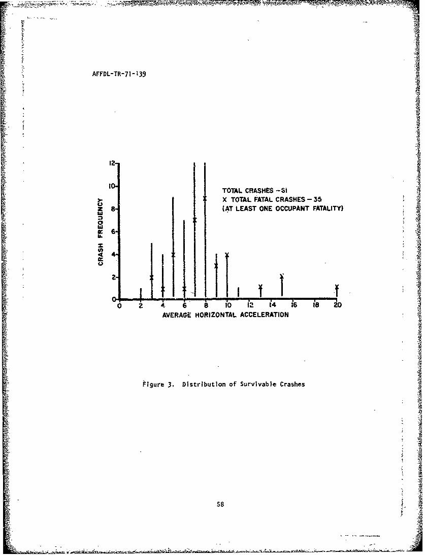
AFFDL-TR-71- 139
TOTAL CRASHES -61X TOTAL FATAL CRASHES- 35
z 8a (AT LEAST ONE OCCUPANT FATALITY)
w€
0 z 1 1 8 14 i6 i8 io
AVERAGE HORIZONTAL ACCELERATION
Figure 3. Distribution of Survivable Crashes
58

AFFDL-TR"-71-139
A-i
Inn
C.q,
13
LLA. LL-
0V 0
' 49
5 ~0
-It
59

AFFDL-TR-71-139
IOI100
90
80
770 /
w
50
:40
~30
ALL CRASHES (MEAN G)
20, _ - FATAL CRASHES (AT LEAST
ONE OCCUPANT FATALITY)
10-
0 2 4 6 81 1 I0 P 12 4 1'6 18 20AVERAZ3E HORIZONTAL ACCELERATION
Figure 5. Hor;zontal A.ceieration Distributign of Fatal Crashes
A4A
60

AFFDL "TR-7 ]-139
100.A.-
SERIOUS
S~90 -"
so-
~7O FATALa70
23 60 .
w 5> 0-
S. •T O TA L C R A S H ES -6 1
40
340
20-
10
OO 00 12 14 ?6 18 20
AVERAGE HORIZONTAL ACCELERATION
Figure 6. Accumulative Percentage of Crew Injuries in the SurvivableRange
61
?61
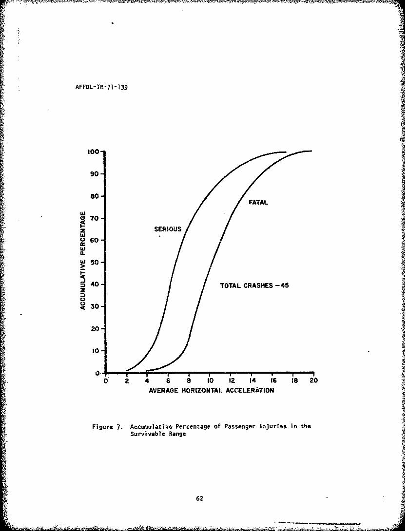
AFFDL-TR--71-139
100
90
w?0-
<30-
S~20 .
to-.
zw U
AVERAGE HORIZONTAL ACCELERATION -4
S~Figure 7. Accumulative Percentage of Passenger Injuries in the •
•! Survivable Range
20
--0! -
0 1 2" 1 8 2

AFFDL-TR-71-139
100
90 ~ ~ ,IiNOR OR NONEFAL
TO
S50
La.!
0
30-SERIOUS
201
10
14 16 Is 2
2 4 6 8 1O 12 14 6 18 2
£ ~FOR WARD G LOAD
Figure 8. Passenger Injury Trends
63

,A
AFFDL-TR-71-139
f 100
MMOR OR NONE FATALso-
Ii, 70"' '
o 50.
40
30
SERIOUS20
0o
0 2 6 8 10 12 14 16 18 20FORWARD G LOAING
Figure 9. Crew Injury Trends
4. ~64 -

054-
#%f FDL-TR-7 1-139
CD
c
I~4 U U
CL
1- 0 C3
04 0
s - Z6 UO v
4Cn 0
I-. - *
-u cC2 0c- go
4A V* 0.
w r 0 c
J.- = us
us En "-4 U- Ono-
- - ~cm 4 T 4
"" , -I 5, -,0p
0,( Mn0~
-~~~~ vI>(0j'~4
EnLa 0
I., S P U 1
0I 0 ~ mE 9U.-4 U.-
0I c
o 0 - 0-
0 U m'U ci -# U 5.ta 0 % Us U-
0. - 4. L.- 1. AS
0 0 U- 0 L. ii 00 L%. 0 UL IL. 'm c-
4~.4 t.2 a 00
__ -i__ _ cou~~-.1 -
65U
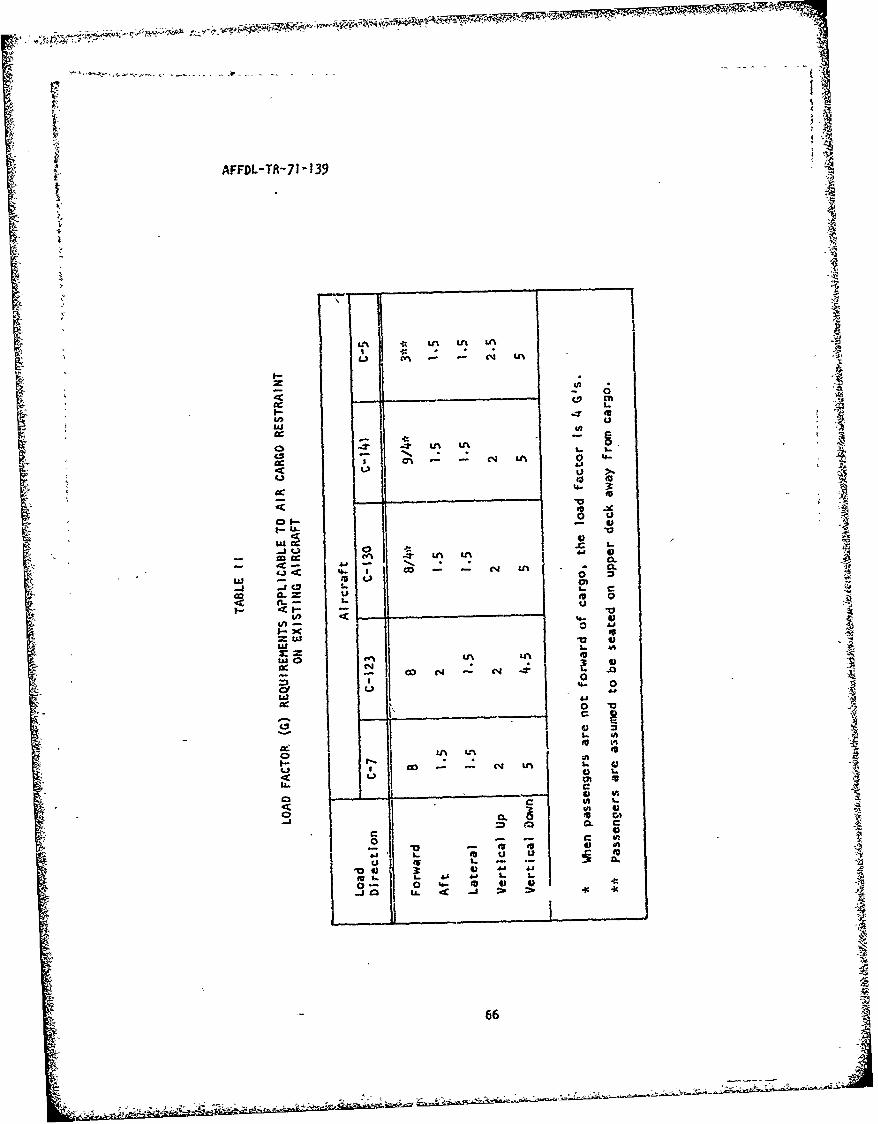
,.
iW
AFFDL-TR-7) 139
In ___ U2
tv
CC' LI'
L)ej4
co~ .a
cc- ON'- 6
4 . e n 4,C CLI
r- ;7- . V
'1. 06
0 .0
CcC
44

AFFDL-TR-71-139 -
4-
NU
%0 0o 43
%D Izco 0% I
I- co ccZ %W -
4 '.0 .0
- 0
4 N - .-J - ____ ____ ____
4 I.I~ nI2 c~ c
o IA 6w

mTC giz 77,~;~ ~ #. ..--
AFFDL-TR-7 1-139
'-j
0 .04
4~ ONN - -
LU
-J U
u -w
I-tt
LU CD C
co La
U. CI - 1 2-
-ý U, x) -ZW = - ma
,4 < = c 0 cD4- CIC w-
a- U. w . D-.)C
L.) LU I
m- 0 5 U- C-.D :
=w =o- LL -ý -
-a IA-< LL< CoI
-, .
(n LL<.L n. III-.IL0WM- PJ )0. _ w
o 4o 4ezx % 4,- -. i- zr -1 e -' o N %0. 1orý

4R
AFFDL-TR-71-139
C'4
w
u's
0Z.
(4r
-- (*44
N N NcN
N N C- - r, -NjN
Go r
.~M.
o Z - r U%;% -r l I-
69

AFFDL-TR-71- 139
4u.s
00
t%.~I'.D ('1 _:r .4 L In N
tot
o 0 t --4 l -4 -N" - LM Na
4 C4
iit
ZZ IIIRS-4
-~ All

- _ - - ---,,,--- ,1•-,•Mr•.` •, , I -; •
AFFDL-TR-71-139
LEGEND FOR TABLE IV, EXPLANATION OF
"PHASE OF OPERATION" COLUMN
Codes 10 through 60 are used to record phase of operation for all
accidents/incidents occurring in flight, or where there was intent for
flight. Codes in the 70 series are used for accidents/incidents where
there was no intent for flight. A•
10 - ENGINES RUNNING, NOT TAXIING - Includes accidents while making
power checks or starting engines.
20 - TAXIING - Any time aircraft is in motion under power with intent
for flight.
21 - To takeoff
22 - From landing
23 - Other areas
30 - TAKEOFF
31 - Roll
32 - Initial climb within five miles of takeoff airport
33 - Discontinued - All attempts to st.p the takeoff run or
climb by reducing power and/or using brakes or other deceleration 4
equipment.
40 - IN-FLIGHT
41 - Normal
42 - Acrobatics - Includes intentional maneuvers of abrupt
change in direction, speed, or altitude.
43 - Climb prolonged- To cruising aititude, change of
Saltitude, etc. (See 32 above).
71JN

W1
AFFDL-TR-71-139
44 - Refueling
45 - Air-to-ground ordnance delivery
46 - Air-to-air ordnance delivery
47 - Low-level flight - Prolonged in accordanca with directed
mission requirements.
48 - Descent - Prolonged, jet penetration, letdown, etc.
49 - Other
50 -LANDING
51 - Approach - All legs in landing pattern. GCA and ILS
included
52 - Flareout
53 - Roll - Ends with application of power for touch-and-go
or go-around (see 60 below; or slows to taxi speed for turn off runway.
54 - Other
60 - GO-AROUND - Aircraft will be considered on go-around until
sufficient altitude and speed have been attained so that-power can be
reduced and the aircraft can maneuver freely.
61 - Premeditated go-around. Touch-and-go.
62 - Unpremeditated go-around. Full stop landing was
originally intended.
70 - NONFLIGHT ACCIDENTS (No intent for flight)
71 - Parked
72 - Towed
73 " Taxiing
74 - Stolen aircraft, whether or not aircraft became airborne.
72

AFFDL-TR-71-139 A
LEGEND FOR TABLE IV, EXPLANATION OFI; "TYPE OF ACCIDENT" COLUMN'
Up tz- three accident types may be coded for one mishap.
01 - Loss of Directional Control - Loss of directional control or
sudden swerve while on ground or water. Ground loops and running off
side of runway during taxi, takeoff, or landing.
02 Wingtip Landin All cases in which an aircraft is landed on X
a wingtip or drags a wingtip. Include such case3 as above involving
tip tanks instead of wingtips.
• • 03 - Wheals-up Landing - All landings in which the landing gear could -.:
not be or was not lowered and locked prior to contact with the ground.
(Excludes cases where collapse occurs during landing roll after initial
landing contact has been made).
O• - Hard Landing - Stalling in or flying into the runway o, other
intended landing space while landing.
05 - Collapse or Retraction of Landing Gear - All retractions and
collapses which occur on the ground except those defined as wheels-up
landings. Either personnel errors or material Failures can be the cause
of this type accident.
06 - Undershoot - Landing short of runway or other intended landing
space.
s 07 - _Overshoot- Landing too fast or too for down the landing area,
L: ~resulting in: i
Sa. Running off the end of the runway.
Sb. Groundlooping, nosing up, or retractinp the gear to preventVN
running off the end.
c. Landing beyond the runways end.A
'73ak

AFFDL-TR-71-139
08 - Aircraft Collision on the Ground - Collisions between aircraft
whtn one or bc-th of the primary aircraft invovied are o; dhe ground and
are not on the takeoff and landing roll.
09 - Aircraft Collision in the Air - Collisions between aircraft
when both of the primary aircraft involved are flying. Aircraft on
the takeoff or landing roll are considered to be flying for pr'poses of
this definition.
10 - Collision with Ground or Water - Includes collisions with
mountains, hills, flying into ground or water, etc. Excludes collisions
preceded by stall, spin or spiral, explosion, airframe or engine failure.
!I - Other Collisions - Collisions with any object other than planes
or ground or water. (1) Aircraft in f'ight collides with poer lines,
trees, t.'v target., birds, etc; (2) Aircraft is engaged in taxiing,
.akeoff roll, or landing rcii, and collides with any object other than
aircraft, such as pý;es, buildings, fences, etc.
12 - Spin or Stall - Mishaps in which the aircraft spins or stalls
into the ground or water. Excludes hard landings and those stalls which
oc:cur above the landing space during the iev.ling-off pro:ess.
13 - Fire and/or Explosion on Ground - Hisbpas resulting frcun and
caused by, 5ire and/or explosion on the ground.
14 - Fire id/or Explosion in the Air - Mishaps result *. from and
caused by, fire and/or explosion ;n the air.
15 - Airframe Failure - Mishaps resulting from failure of any part of
the airframe, ý.uch as wingspars, empennage, hinges, and fuselage skin.
Includes structural failure where safe landing was effected with no
further damage. includes cases where the canc.py or hatches come- off in
flight and are not caused by the action or inaction of person(s).
74

AFFDL-TR-71-139
16 - Abandoned Aircraft - Aircraft abandoned in flight by all personnel
capable of pioting aircraft.
I? - Propelkr or Jet Mishap on Ground - Mishaps In which a person
suffers injury from contact with a rotating propeller or from a turbojet-
engioe intake. Also used for mishaps caused by prop or jet blast
resulting in injury to personnel or damage to any equipment, tuilding,
etc.
98 - Type of accident - Not determined.
YY - Not Applicable - Enter this code in any ot the three spaces
where no other type of Accident is used.
"* 7S

L4
AFFDL-TR-71-139
TABLE V
POTENTIAL COST SAVINGSFOR CONTAINER UTILIZATION 1965-68
ITEM AMOUNT ($ MILLION)
Cost Avoidance
Pipeline Reduction 1968 level 147.2
Port Facilities 181.0
Snip Delay Billings 89.7
Covered Storage 86.9
Refrigerated Ste-age ý3.0TOTAL COST AVOIDANCE 527.8
Recu~rring Saving (1965 to 1968)
Shipmn-ts (Incl. Port Handling) 344.6
Depot Cargo Handling 8.9
TOTAL RECURRING SAVINGS 353.5
GRAND TOTAL 881.3
"76

AFFDL-TR-71-139
APPENDIX I
C-130 AIRCRAFT JIAJOR ACCIDENTDATA ANALYSIS
The IGDS major cargo aircraft accident data for 1962 to July 1971
contained ninety C-130 accidents. Table VI is a summary of these
accidents by years, showing personnel injury data; a breakout of the •accidents not considered crashes (i.e., ground refueling accidents,
major damage during towing operaticis, etc); and, for the crashes an
estimate of the crash force levels was made.
The percentage relationship of crash force level of total crashes
(62 cases) is:
O to 3 G 3 G to h/S N/S
48.4• 25.8% 25.8%
Thr following are example C-130 cases identified by the crash force
level into which they were placed.
THIS IfORMATION IMrEY'?IGNALLY DELMED
"77

AFFDL-TR-7 1-139
on 7 July 1966. A loud noise was heard on landing, a go-around was per-
formed, and it was found that the right main landing gear was hanging
down. After the cargo was jettisoned a crash landing was made on a
foamed runway.
I
TMIS INFCRMATION INTENTIONAL.LY DELETED
4
•10
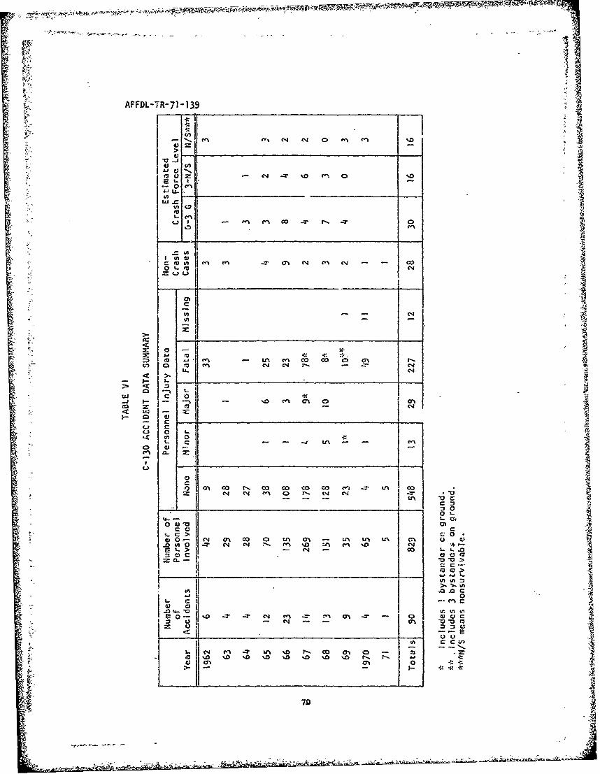
rl
AFFDL-TR-71-139
1 0
ri v z 0 f-J (V N-0,- zit - - --,____ _ _, _ ____ ,
0J U.
2nenui.,z
C4'In M
0'-- -0
ii (
toi~7 C
2:~ 0 ~2:0 1-0
0 a. IN
s-: >~I -o %-
Li CLi 0
M C
0~ ~ ~ J,' C%4 f"u%-T4
0a %0 % 0 .aVC Cf I
~4 -Z0-
-~ N '- ~~ 79

ASD-TR-73-17
REFERENCES
I. "Air Transport of Supplies/Equipment," TM 55-450-10/2, AFM 76-4,March 1971.
2. Haley, J. L., et al, "Floor Accelerations and Passenger Injuriesin Transport Aircraft Accidents," USAAVLABS TR 67-16, fay 1967.
3. "USAF Aircraft Accident Summary 1970," Directcrate of AerospaceSafety, IGDS.
4. Turnbow, J W., et al, "Crash Survival Design Guide," USAAVLABSTR 70-22, August 1969.
5. Berger, S., et al, "A Critical Analysis of the State of the Artin Containerization," US Army Mobility Equipment Research andDevelopment Center, November 1969.
6. "Logistic Support in the Vietnam Era," Monograph 7-Containerization,Joint Logistics Review Board.
7. Sadlocha, S. P., et a], "Airlift Container Parametric Study,"AFLC-TR-70-8, Serstember Jq7 0.
8. J. F. Goodwin, et al, "Post 1971 Materials Handling Study,"ASD-TR-67-5.
9. Caughey, R. J., "Cargo Restraint Criteria," Douglas AircraftCompany, CAPDOC-DAC-68-29, Uctober 1968,
10. Avery, J. P., "Cargo Restraint Concepts for Crash Resistance,"AUSER TR 64-13, June 1965-.
11. Reed, W. H., et al,"Full Scale Dynamic Crash Test of a DouglasDC-7 Aircraft," FAA-ADS-37, April 1965.
12. Reed, W. H., et al,'Ful)-Scale Dynamic Crash Test of a LockheedConstellation Model 1649 Aircraft," FAA ADS-38, October 1965.
13. US Air Force Accident Bulletins, 1960 through 197P, Directorateof Aerospace Safety, IG for Inspection and Safety, USAF. Norton,AFB, California.
j4. 64 USAF Accident Reports, Cargo Aircraft, 9 August 1968 to27 February 1971.
15. Muller, G. E., "Crash Survival and Structural Design Criteria,"FDTE-C Memorandum, August 1969.
16. Weingarten, J. L., at al, "Air Cargo Restraint Criteria,"AFFDL-TR-71-139, January 1972.
-. P