i,+,i. - defense technical information center · i,+,i. • -',. t ,g44" + ; ad-a243 139...
TRANSCRIPT

• I,+,I. - ',. T ,g44" + ;
AD-A243 139fl l11NCS TIB 90-19
)NATIONAL COMMUNICATIONS SYSTEM
TECHNICAL INFORMATION BULLETIN 90-19
ANALYSIS OF
GOVERNMENT FACSIMILE
EQUIPMENT AND NETWORKS
MAY 1991
OFFICE OF THE MANAGER
NATIONAL COMMUNICATIONS SYSTEM
WASHINGTON, D.C. 20305
91-16706
91 i 4,+ui

A
May 1991 Final
Analysis of Government Facsimile Equipment andNetworks C-DCA100-87-C-0078
Delta Information Systems, Inc.Horsham Business Cneter, Bldg. 3 Suite 120300 Welsh RoadHorsham, PA 19044-2273
National Communications SystemOffice of Technology & Standards701 S. Court House Road NCS TIB 90-19Arlington, VA 22204-2199
Approved for Public Release; distribution isunlimited.
The purpose of this task is to investigate strategic and tactical facsimile equip-ments and networks employed by the Federal government (including both thosecurrently in the field and those due for deployment in the near future), determinetheir characteristics in terms of interoperability and compatibility, and, inthose instances where incompatibilities are determined, to recommend how they mightbe made to interoperate. The Feeral government uses a wide range of facsimileequipment and networks ranging from commercial, off-the-shelf equipments designedfor the office to special ruggedized equipment designed for the battlefield. Ingeneral, these equipment fall into two categories: strategic and tactical.Strategic equipments are used in office-like surroundings where the environment isusually well controlled, and operate over networks like the Public SwitchedTelephone Network (PTN) and the Defense Communications Network (DCN). Two examplesof strategic equipments are off-the-shelf, commercially available facsimileequipments (Group 3, etc.) and commercially available equipments modified tocommunicate through encryption devices. Tactical equipments, on the other hand,ae used in harsh battlefield environments, operate over networks like the Mobile(See
back)Public Switched Telephone Networks (PSN) Group 3 114Facsimile
Unclassified Unclassified Unclassified Unlimited

GENERAL INSTRUCTIONS FOR COMPLETING SF 298The Report Documentation Page (RDP) is used in announcing and cataloging reports. It is importantthat this information be consistent with the rest of the report, particularly the cover and title page.Instructions for filling in each block of the form follow. It is important to stay within the lines to meetoptical scanning requirements.
Block 1. Agency Use Only (Leave Blank) Block 12a. Distribution/Availablity Statement.Denote public availability or limitation. Cite
Block 2. Report Date. Full publication date any availability to the public. Enter additionalincluding day, month, and year, if available (e.g. limitations or special markings in all capitals1 Jan 88). Must cite at least the year. (e.g. NOFORN, REL, ITAR)
Block 3. Type of Report and Dates Covered.State whether report is interim, final, etc. If DOD - See DoDD 5230.24, Distributionapplicable, enter inclusive report dates (e.g. 10 Seenon TechnialJun 87 - 30 Jun 88). Statements on Technical
Documents."
Block 4. Title and Subtitle. A title is taken from DOE - See authoritiesthe part of the report that provides the most NASA - See Handbook NHB 2200.2.meaningful and complete information. When a NTIS - Leave blank.report is prepared in more than one volume,repeat the primary title, add volume number,and include subtitle for the specific volume. On Block 12b. Distribution Code.classified documents enter the titleclassification in parentheses. DOD - DOD - Leave blank
DOE - DOE - Enter DOE distribution categoriesBlock 5. Funding Numbers. To include contract from the Standard Distribution forand grant numbers; may include program Unclassified Scientific and Technicalelement number(s), project number(s), task Reportsnumber(s), and work unit number(s). Use the NASA - NASA - Leave blankfollowing labels: NTIS - NTIS - Leave blank.
C - Contract PR - ProjectG - Grant TA -TaskPE - Program WU - Work Unit Block 13. Abstract. Include a brief (Maximum
Element Accession No. 200 words) factual summary of the mostsignificant information contained in the report.
Block 6. Author(s). Name(s) of person(s)responsible for writing the report, performing Block 14. Subject Terms. Keywords or phrasesthe research, or credited with the content of the identifying major subjects in the report.report. If editor or compiler, this should followthe name(s). Block 15. Number of Pages. Enter the total
Block 7. Performing Organization Name(s) and number of pages.Address(es). Self-explanatory. Block 16. Price Code, Enter appropriate price
Block 8. Performing Organization Report code (NTIS only).Number, Enter the unique alphanumeric reportnumber(s) assigned by the organization Blocks 17. - 19. Security Classifications.performing the report. Self-explanatory. Enter U.S. Security
Classification in accordance with U.S. SecurityBlock 9. Sponsoring/Monitorino Agency Regulations (i.e., UNCLASSIFIED). If formNames(s) and Address(es). Self-explanatory. contains classified information, stamp
Block 10. S1onsorina/Mon itoring Agency, classification on the top and bottom of the page.
Report Number. (If known)Block 11. Supplementary Notes., Enter Block 20. Limitation of Abstract. This blockinformat ol a n otincludedeseer ucmust be completed to assign a limitation to theinformation not included elsewhere such as: abstract. Enter either UL (unlimited) or SAR
Prepared in cooperation with...; Trans. of ..., To as r t). Ent r iited) or s
be published in .... When a report is revised, (same as report). An entry in this block is
include a statement whether the new report necessary if the abstract is to be limited. If
supersedes or supplements the older report. blank, the abstract is assumed to be unlimited.Standard Form 298 Back (Rev. 2-89)

Subscriber Equipment Network (MSE), and must be able to endure dirt, mositure,temperature extremes, shock, and vibration. Examples of tactical facsimileequipments are the Tactical Digital Facsimile AN/UXC-4 and the lightweightAN/UXC-7.

NCS TECHNICAL INFORMATION BULLETIN W 9._1
ANALYSIS OFGOVERNMENT FACSIMILE EQUIPMENT AND NETWORKS
MAY 191
PROJECT OFFICER APPROVED FOR PUBLICATION:
STEPHEN PERSCHAU DENNIS BODSONComputer Scientist Assistant ManagerOffice of NCS Technology Office of NCS Technology
and Standards and Standards
FOREWORD
Among the responsibilities assigned to the Office of the Manager, NationalCommunications System, is the management of the Federal TelecommunicationStandards Program. Under this program, the NCS, with the assistance of theFederal Telecommunication Standards Committee identified, develops, andcoordinates proposed Federal Standards which either contribute to theinteroperability of functionally similar Federal telecommunication systems orto the achievement of a compatible and efficient interface between computer andtelecommunication systems. In developing and coordinating these standards, aconsiderable amount of effort is expended in initiating and pursuing jointstandards development efforts with appropriate technical committees of theInternational Organization for Standardization, and the International Telegraphand Telephone Consultative Committee of the International TelecommunicationUnion. This Technical Information Bulletin presents and overview of an effortwhich is contributing to the development of compatible Federal, national, andinternational standards in the area of facsimile. It has been prepared toinform interested Federal activities of the progress of these efforts. Anycomments, inputs or statements of requirements which could assist in theadvancement of this work are welcome and should be addressed to:
Office of the ManagerNational Communications SystemATTN: NCS-TSWashington, DC 20305-2010 .
/
, 1'..q

ANALYSIS OFGOVERNMENT FACSIMILE EQUIPMENT
AND NETWORKS
May, 1991
SUBMITTED TO:NATIONAL COMMUNICATIONS SYSTEM
Office of Technology and StandardsWASHINGTON, D.C. 20305
Contracting Agency:DEFENSE COMMUNICATIONS AGENCY
Contract Number - DCA100-87-C-0078Task Number - 89-003
DELTA INFORMATION SYSTEMS, INCHorsham Business Center, Bldg. 3, Ste 120
300 Welsh RoadHorsham, PA 19044-2273
TEL: (215) 657-5270 FAX: (215) 657-5273

CONTENTS
ILL USTRA TIONS ............................................... iv
TABLES . . . . . . . . . . . .. . . . . . . .. . . . .. . . . .. . . . . . .. . . . . . . . . .. . . . . . v
1.0 INTRODUCTION ........................................... 1- 1
2.0 FEDERAL GOVERNMENT FACSIMILE EQUIPMENTS ................... 2 - 12.1 Tactical Facsimile Equipments ............................... 2 - 12.2 Strategic Facsimile Equipments .............................. 2 - 3
3.0 CAPABILITIES AND CHARACTERISTICS ........................... 3 - 13.1 Tactical Networks ...................................... 3 - 1
3.1.1 Extremely Low Frequency (ELF) Communications Systems ....... 3 - 13.1.2 Fleet Satellite Communications System (FLTSATCOM) .......... 3 - 23.1.3 Joint Tactical Information Distribution System (JTIDS) .......... 3 - 23.1.4 Tri-Tac Joint Tactical Communications System ............... 3 - 2
3.2 Strategic Networks ...................................... 3 - 23.2.1 Defense Communications System (DCS) .................... 3 - 33.2.2 Defense Data Network (DDN) .......................... 3 - 33.2.3 Defense Switched Network (DSN) ........................ 3 - 33.2.4 Ground Wave Emergency Network (GWEN) ................ 3 - 4
3.3 Tactical Facsimile ...................................... 3 - 43.3.1 STANAG Type I - Black and White Imagery ................ 3 - 5
3.3.1.1 Communication Protocol ........................ 3 - 53.3.1.2 Data Compression ........................... 3 - 53.3.1.3 Transmission Rate ........................... 3 - 6
3.3.2 STANAG Type II - Gray Scale Imagery ................... 3 - 73.3.2.1 Communication Protocol ......................... 3 - 73.3.2.2 Data Compression ........................... 3- 73.3.2.3 Transmission Rates ........................... 3 - 8
3.4 Strategic Facsimile ...................................... 3 - 93.4.1 Group III Facsimile ................................ 3 - 9
3.4.1.1 Communication Protocol ........................ 3 - 103.4.1.2 Encoding Algorithm ........................... 3 - 103.4.1.3 Transmission Rate .......................... 3 - 113.4.1.4 Planned Future Expansion ...................... 3 - 11
3.4.2 Group IV Facsimile ............................... 3 - 163.4.2.1 Communication Protocol ........................ 3 - 193.4.2.2 Encoding Algorithm ........................... 3 - 233.4.2.3 Transmission Rate .......................... 3 - 233.4.2.4 Planned Future Expansion ...................... 3 - 23
ii

4.0 COMPATIBILITY ANALYSIS....................................... 4 -1
5.0 RECOMMENDATIONS........................................... 5 - 1
REFERENCES.............................................. References - 1
STANAG 5000............................................... Appendix A

ILLUSTRATIONS
Figure 3-1. Example of a "Wobbled" Line .............................. 3 - 8Figure 3-2. Original Scanned with Square Pels ........................... 3 - 14Figure 3-3. Facsimile Printed using Rectangular Pels .......................... 3 - 14Figure 3-4. Hierarchy of CCITT Recommendations for Group 4 Facsimile .......... .3 - 18Figure 3-5. The OSI M odel ...................................... 3 - 20Figure 4-1. Computer Controlled Facsimile Equipment ....................... 4 - 4Figure 4-2. Facsimile Equipment with In-line Encryption ..................... 4 - 4Figure 4-3. Facsimile Equipment with Peripheral .......................... 4 - 4Figure 4-4. Computer Controlled Facsimile Equipment with Peripheral ............... 4 - 5
iv

TABLES
Table 3-1. Comparison of Transmission Methods ........................... 3 - 6Table 3-2. Group 3 Resolutions .................................... 3 - 13Table 3-3. Group 4 Class Characteristics .............................. 3 - 17Table 3-4. CCITT Recommendations Pertaining to ISDN Group 4 Operations ........ .3 - 21Table 4-1. Comparison of Strategic and Tactical Facsimile ...................... 4 - 1Table 4-2. Interoperability of Facsimile Equipments .......................... 4 - 3
V

1.0 INTRODUCTION
This document summarizes work performed by Delta Information Systems, Inc., for the
Office of Technology and Standards of the National Communications System, an organization of
the U. S. Government, under Task 3 of contract number DCA 100-87-C-0078. The purpose of this
Task is to investigate strategic and tactical facsimile equipments and networks employed by the
Federal government (including both those currently in the field and those due for deployment in
the near future), determine their characteristics in terms of interoperability and compatibility, and,
in those instances where incompatibilities are determined, to recommend how they might be made
to interoperate.
The Federal government uses a wide range of facsimile equipments and networks ranging
from commercial, off-the-shelf equipments designed for the office to special ruggedizedequipments designed for the battlefield. In general, these equipments fall into two categories:
strategic and tactical. Strategic equipments are used in office-like surroundings where the
environment is usually well controlled, and operate over networks like the Public Switched
Telephone Network (PSTN) and the Defense Communications Network (DCN). Two examples
of strategic equipments are off-the-shelf, commercially available facsimile equipments (Group 3,
etc.), and commercially available equipments modified to communicate through encryption
devices. Tactical equipments, on the other hand, are used in harsh battlefield environments,
operate over networks like the Mobile Subscriber Equipment Network (MSE), and must be able
to endure dirt, moisture, temperature extremes, shock, and vibration. Examples of tactical
facsimile equipments are the Tactical Digital Facsimile AN/UXC-4 and the lightweight
AN/UXC-7.
Besides their environment, the equipments belonging to these two categories differ in
several ways. Some of which are listed below:
- Communication protocols- Facsimile imagery (Black and white, gray scale)- Compression techniques- Transmission rates
1-1

- Encryption capability
Each phase of the study is discussed in the following sections. For example, section 2,"FEDERAL GOVERNMENT FACSIMILE EQUIPMENTS," describes strategic and tacticalequipments used by the Federal government.
Section 3, "CAPABILITIES AND CHARACTERISTICS," describes the capabilities andcharacteristics of strategic and tactical networks and strategic and tactical facsimile equipments.
Section 4, "COMPATIBILITYANALYSIS," compares strategic and tactical equipments, anddiscusses their interoperability.
Section 5, "RECOMMENDATIONS," recommends how equipments which are notinteroperable could be made so.
1-2

2.0 FEDERAL GOVERNMENT FACSIMILE EQUIPMENTS
As mentioned before, the Federal government uses a wide range of facsimile equipments.
These equipments are used to send facsimiles between the military, industrial concerns,
contractors, and government agencies. Secondly, depending on the concern, the type of facsimile
capability required varies. For example, the military requires gray scale facsimiles to be sent in
a secure fashion (encrypted). They need to be able to transmit imagery, like photos or maps, to
commanders in the field without revealing the imagery or the locations of the participating sites
to the enemy. Whereas, government agency to industry facsimile transmissions are usually just
black and white with no encryption (business letters, etc.). This section describes actual strategic
and tactical equipments, and where and how they are used.
2.1 Tactical Facsimile Equipments
The military is the principal user of tactical facsimile equipment. They use tactical
facsimile to transmit written orders, maps, photos, etc. over tactical transmission circuits from
one battlefield post to another, from one centralized command post to another, or a mixture of
ooth.
In general, these equipments must be rugged enough to endure harsh environments; they,
like the soldiers using them, are exposed to the vigors of the battlefield and the fury of the
weather. They must be able to endure extremes of temperature (freezing cold to broiling hot),
too much or too little moisture, and shock and vibration. In addition, they must be portable, and
must have low power consumption needs. Moreover, in this environment, these equipments must
provide field commanders with high quality facsimiles quickly and se-'urely. They must be quick
to minimize revealing friendly positions to the enemy, and they must be secure to thwart enemy
eavesdropping.
The military uses several types of tactical facsimile equipments. For example, the
AN/GXC-7A Tactical Facsimile, manufactured by Magnavox Government and IndustrialElectronics, Co., Torrance, CA, has been used by the U.S. Government since 1982. It features
a carbon paper tiansfer method that can print on any type of paper, 8 shades of gray for
2-1

photographic imagery, and a 40 second transfer time for a typical tactical facsimile message (216mm x 356 mm). In addition, it can be mounted on vehicles for mobile communications, or canbe used in sheltered environments.
The AN/GXC-7B Tactical Facsimile, also manufactured by Magnavox Government andIndustrial Electronics, Co., Torrance, CA, is an improved version of the AN/GXC-7A, and hasbeen used by the U.S. Government since 1983. The AN/GXC-7B Tactical Facsimile providesboth analog and digital facsimile transmission capabilities. The digital transmission capabilityallows the AN/GXC-7B to transmit over high speed communications channels (up to 32 Kilobitsper second(Kbps)), and a typical tactical facsimile message can be transmitted in less than 28seconds at 16 Kbps. Other features include three modes of transmission (non-compressed,compressed, and compressed with forward error correction), storage of a full page fortransmission while simultaneously receiving a facsimile message, NATO (STANAG 5000)interoperability, and interoperability with most cryptographic equipment (including Tempest andthe U. S. Tri-Tac system). The AN/GXC-7B is designed to be mounted on vehicles, or on shipor airborne platforms. Nevertheless, it can be easily removed for operation in shelteredenvironment.
The AN/UXC-4 Tactical Digital Facsimile, manufactured by Litton Systems, Inc.,Amecom Division, College Park, MD, has been used by the U.S. Government since the early1980's. The AN/UXC-4 is designed to give field commanders high quality pictorial anddocumentary information in near real-time. The AN/UXC-4's features include a laser on dry,electrophotographic paper transfer method that meets full tactical environment standards, 4, 8, or16 shades of gray for photographic imagery, a less than 25 second transfer time for a typicaltactical facsimile message at 9600 bits per second, four resolution modes, including 8 x 7.7lines/mm, 8 x 3.85 lines/mm, 4 x 3.85 lines/mm, and automatic, where the resolution adjusts toimage content accordingly, NATO (STANAG 5000) interoperability, selected data rates from 1.2- 32 Kbits per second, full duplex operation, where imagery can be both transmitted and receivedsimultaneously, and broadcast transmission capability, where an image can be transmitted tomultiple receiving stations simultaneously. The digital operation of the AN/UXC-4 was designedprimarily to operate within the U. S. Tri-Tac system, but the unit can operate with mostcryptographic equipment (including Tempest and Tri-Tac). In addition, it is designed as astationary unit for sheltered environments; but has a degree of portability - it can be carried bytwo men.
2-2

The AN/UXC-7 Lightweight Digital Facsimile, manufactured by Magnavox Advanced
Products and Systems Co., Torrance, CA, has been used by the U.S. Government since 1989 as
a part of the Mobile Subscriber Equipment (MSE) network. The AN/UXC-7 is an improvedversion of the AN/GXC-7A Tactical Facsimile. The AN/UXC-7 features include a carbon paper
transfer method that can print on any type of paper, 8 shades of gray for photographic imagery,
a message memory that allows for burst message transmission, transmitting a message (215 mmx 279 mm) in less than 15 seconds at 16 Kbits per second, three modes of transmission
(non-compressed, compressed, and compressed with forward error correction), NATO (STANAG
5000) and MIL-STD-188 compatibility, both digital and analog transmission capability, and
transmission rates between 75 bits per second and 32 Kbits per second. The digital operation of
the AN/UXC-7 was designed to operate with both MIL-STD-188 and NATO equipment; the unit
also operates with most cryptographic equipment (including STU-III and COMSEC). The
AN/GXC-7B is a one-man portable equipment and can operate in any environment.
The TSF3800 Tactical Secure Facsimile, manufactured by 3M, St. Paul, MN, has been
used by the U.S. Government since 1983. It's features include a thermal transfer method thatmeets full tactical environment standards, resolutions of 8 x 7.7 lines/mm and 8 x 3.85 lines/mm,
NATO interoperability (Type I only), selected data rates from 0.6 - 32 Kbits per second, and
digital operation. The digital operation of the TSF3800 was designed to operate with Type I
NATO equipment, the unit also operates with most cryptographic equipment (including Tempest
and Tri-Tac). In addition, the TSF3800 is a one-man portable equipment, and can operate in any
environment.
2.2 Strategic Facsimile Equipments
Strategic facsimile equipments are used by both the military and government agencies.
Since they are used primarily in the office, requirements for them are, in general, less stringent
than those for tactical facsimile equipments. For instance, they do not have to be ruggedized, nor
do they have to be portable, nor do they have to be able to simultaneously transmit to more than
one receiver. Moreover, strategic facsimile equipments usually serve in a capacity similar to the
role played by facsimile equipments found in the general public. In fact, a large number of the
strategic equipments are the same brand equipments found in the public and private sectors.
2-3

Nevertheless, the Federal government does have some special requirements which the
commercially available equipments are unable to fulfill. For example, the Federal government
needs strategic facsimile equipments which transmit documents securely. Secondly, some of theseequipments must be able to interoperate with tactical equipments. The strategic equipments the
Federal government uses to fulfill these roles are, in general, modified, commercially available
equipments; tactical facsimile equipments could be used, but their higher cost (because they are
ruggedized) versus the lower cost of modified, commercially available machines make the
commercial equipments more attractive. Two examples of secure strategic equipments are the
Model 750T Secure Facsimile, manufactured by Ilex Systems Inc., Milpitas, CA, and the Model
750 non-Tempest version. In addition, non-secure, commercially available, off-the-shelf
(strategic) equipments are available from a number of manufacturers. A few of these
manufacturers are Sony, Panafax, and Ricoh.
2-4

3.0 CAPABILITIES AND CHARACTERISTICS
This section discusses tactical and strategic networks, and tactical and strategic facsimile
equipments used by the U.S. Government.
3.1 Tactical Networks
The U.S. military operates a number of tactical networks such as the Extremely Low
Frequency (ELF) communications system, the Fleet Satellite Communications System
(FLTSATCOM), the Joint Tactical Information Distribution System (JTIDS), and the Tri-Tac
Communications System.
3. 1.1 Extremely Low Frequency (ELF) Communications Systems
The ELF communications system uses extremely low frequency (40-80 Hz) radio signals
to communicate with submerged submarines. ELF was first proposed 30 years ago, but the
extremely large antenna size and environmental worries prevented its use until recently.
ELF signals travel great distances with low loss and penetrate sea water to great depths.
In practice, one or more shore-based transmitters use long horizontal and orthogonal wire antennas
earthed at each end to send messages (One transmitter has 22.5 kilometer (km) long antennas, and
orthogonal antennas are used to provide omni-directional radiation patterns). Once transmitted,
submarines are able to receive these messages using towed antennas. Because the bandwidth is
low at ELF, the message transmission rate is very slow; but by using simple three letter code
systems, a great number of messages can be sent in a reasonable time.
3.1.2 Fleet Satellite Communications System (FLTSATCOM)
3-1

FLTSATCOM provides multi-channel UHF communications for the US Navy. It alsosupports US Air Force bombers and launch control centers, all airborne command posts, and someUS Army nuclear capable force elements.
3.1.3 Joint Tactical Information Distribution System (JTIDS)
JTIDS is a US joint-service, jam-resistant, secure communications system, and allows theinterchange of information between aircraft, surface vessels, mobile or fixed-base land stations,and command centers. It is a flexible, multiple-user tactical information exchange service, usesdigital and voice links operating in the 960-1215 MHz band, and uses spread spectrum techniquesto increase jam resistance.
User inputs automatically include identification and navigation data in addition to targetacquisition details. Users may continuously monitor or sample the database for any informationthey may require. Nevertheless, recipients are usually unaware of the providers of theinformation; just as providers are usually unaware of the recipients.
3.1.4 Tri-Tac Joint Tactical Communications System
Tri-Tac is a hybrid system designed to allow a transition from analog systems to a fullydigital and automatic system. In general, it combines both telephony and radio communications,and permits facsimile transmissions. Telephonic communications are, in general, provided by themobile subscriber equipment (MSE); which is a corps-wide, common user telephone system whichserves both stationary and mobile users.
3.2 Strategic Networks
The strategic networks include commercial networks, the Defense Communications System(DCS), the Defense Data Network (DDN), the Defense Switched Network (DSN), and the GroundWave Emergency Network (GWEN).
3-2

3.2. 1 Defense Communications System (DCS)
The DCS is the world wide strategic communications system used by the US DoD for day-
to-day operations, and is the heart of the wartime communications system for the National
Command Authorities, the Joint Chiefs of Staff, the Commanders-in-Chief, and other critical
users. It comprises government-owned and operated communications facilities and circuits leased
from commercial telecommunications companies. The government-owned portion includes all
long-haul assets of the military except those devoted to tactical communications, and are mostly
based outside the U.S. Transmission media include line-of-sight radio, over-the-horizon
tropospheric scatter radio, HF radio, satellites, and cable.
3.2.2 Defense Data Network (DDN)
The DDN is the successor to the Autodin II network program which was canceled in 1982.
The DDN is a packet switching system based upon ARPANET. It currently connects around 750
host computers and 30,000 users.
3.2.3 Defense Switched Network (DSN)
The DSN is an overlay network designed to be part of the US telephonic common carrier
system, and is replacing the dedicated AUTOVON telephone network. The DSN consists of
virtual software packages which common carriers are paid to add to their digital switching nodes
in existing commercial networks. The software will handle all military switching needs over
regular networks, and will permit the use of encrypted voice.
AUTOVON is a world-wide, mainly analog, circuit switched network for telephone and
data transmission and serves the DoD and other authorized users.
3.2.4 Ground Wave Emergency Network (GWEN)
GWEN is designed to be a survivable communications network to be used by the command
and control of US strategic forces both during and after nuclear war. The network consists of a
3-3

large number of low frequency (150-175 kHz) unmanned broadcast-type radio relay stations
distributed throughout the continental U.S. GWEN handles low speed (100 words per minute)
data traffic and employs packet-switching for rapid re-routing of messages around destroyed or
non-functioning relay stations. Thus, the system can continue to operate despite considerable
damage.
3.3 Tactical Facsimile
Providing tactical facsimile services demands the best fax has to offer under extremely
harsh conditions. For example, tactical facsimile equipments are often called upon to provide
accurate gray scale images in conditions ranging from the heat of the desert, to the wetness of
tropical forests, to the numbing cold of polar ice caps. In addition, their transmissions must be
brief and secure. Tactical facsimile equipments need gray scale capabilities to provide accurate
and detailed facsimiles of maps, charts, photos, etc., and brief and secure transmissions are
needed to thwart enemy eavesdropping. Finally, the facsimile services must be provided over
the same communication links used for secure and non-secure voice communications (telephony,
radio, etc); i.e., no special communication links
Because of these requirements, the U.S. military services and the military services of other
member nations of the North Atlantic Treaty Organization (NATO) devised a standard, STANAG
5000, which allows their tactical facsimiles to interoperate."t To wit, the STANAG 5000 standard
defines secure interoperability requirements for black and white and gray scale facsimile
equipments.
The STANAG 5000 standard defines two types of facsimile equipments known as Type
I and Type II. Type I encompasses black and white facsimile equipments only. Type II
encompasses Type I and gray scale equipments. Furthermore, the standard defines permitted
modes of interoperability. For example, one equipment transmitting simultaneously to several
equipments, operation over simplex, half duplex, and full duplex links.
3.3.1 STANAG Type I - Black and White Imagery
3-4

The STANAG Type I standard defines the requirements for a baseline system providingblack and white facsimile transmissions. It is the military equivalent of a commercially available
Group 3 equipment.
3.3. 1.1 Communication Protocol
Facsimile equipments (Type I or Type II) adhering to the STANAG standard use a digitalinterface for data exchange. The developers of the STANAG standard felt that digitalcommunications are easier to safeguard than analog communications, and using a digital interfaceallows users to take advantage of existing digital encryption devices. In general, a STANAGcompliant equipment connects to an encryption device which in turn connects to a communicationsequipment. Given this configuration, STANAG compliant equipments are usually unaware of theencryption of their transmissions and how their transmissions get to their destinations.Nevertheless, they are aware of the protocol which allows them to synchronize with otherSTANAG compliant equipments for the purpose of controlling and exchanging documents. Theprotocol is relatively simple (as compared to Group 3 or Group 4). In general, it uses two flags,Start of Message (SOM) and End of Message (EOM) to indicate the start and end, respectively,of a page of a facsimile document.
3.3.1.2 Data Compression
Type I facsimiles may be sent using one of three compression formats:
1. Uncompressed facsimile data with line synchronization codes.2. Compressed facsimile data using one-dimensional run-length codes.3. Compressed facsimile data using one-dimensional run-length codes (like 2.) and
Forward Error Correction (FEC).
These three formats provide different degrees of transmission durations, reduced equipmentcomplexity, and data integrity. Unfortunately, improving one often comes at the expense of atleast one of the other two. For example, improving error correction often results in lower
compression ratios and higher equipment complexity (See Table 3-1).
3-5

Table 3-1. Comparison of Transmission Methods
The data compression technique for (2) I Err
and (3) uses the one dimensional portion of the Metod Compression CorrectionI Complexity
International Telegraph and Telephone Uncompressed None Minimal Small
Consultative Committee's (CCITT) Group 3 C
coding scheme (CCITT Recommendation T.4). Compressed Highest Moderate ModerateCompressed
Nevertheless, this doesn't mean documents can with Error Moderate kst HighCorrection
be exchanged between a STANAG compliant Crt
equipment and a Group 3 compliant equipment.
Both the modems and the protocols are different.
The one-dimensional portion of the CCITT's coding scheme (as well as the two-
dimensional portion) codes documents according to a fixed, non-adaptive coding table. In general,
it assumes short black runs will be separated by long white runs. The CCITT developed this table
based upon studies which indicated most facsimile transmissions are usually textual, and which
demonstrated "acceptable" compression ratios could be achieved for most documents using a code
table determined from a few sample documents. Moreover, the fixed code table scheme, as
opposed to most adaptive coding schemes, is relatively easy to implement.
3.3.1.3 Transmission Rate
STANAG compliant equipments typically operate at a rate determined by the connected
communications equipment (their clock rate is derived from the communications equipment).
Nevertheless, they must be able to interoperate at 2.4 and 16 Kilobits per second (Kbps), and at
rates between 1.2 and 16 Kbps. Thus, for an uncompressed 81/2 x 11 inch document (1728 pels
x 1076 lines) transmission times of roughly 2 minutes at 16 Kbps can be expected, or 25 minutes
at 1.2 Kbps. If compression is used and a minimum compression of 10:1 is achieved, then
compressions times of 12 seconds for 16 Kbps and 2.5 minutes for 1.2 Kbps can be realized. One
could conclude from this that compression "increases" transmission rates and is therefore
desirable. This would be especially true for lower rate communications where long transmissions
risk revealing friendly positions to the enemy, or unnecessarily "tie up" a communications
network or link which might be needed for oiner, possibly higher priority, verbal or non-verbal
communiques.
3-6

3.3.2 STANAG Type II - Gray Scale Imagery
STANAG Type II compliant equipments improve on the Type I equipments by allowingthe transmission of three types of gray scale images. These image types differ only in thepermitted shades of gray; for example, an image type may have either 4, 8, or 16 shades of gray.
3.3.2.1 Communication Protocol
The protocol used for Type II transmissions is identical to that used for Type Itransmissions with a few exceptions; special codes are used to indicate gray scale, low resolution,and auto resolution data follow.
3.3.2.2 Data Compression
Gray scale images are preprocessed before they are encoded. First, each picture element(pixel) is reduced to one of 16 shades of gray (4 bits), and, if necessary, is further reduced (forinstance, to 3 bits). Once reduced, the bits of the pixels are processed as bit planes. Forexample, all the most significant bits are encoded, then the next most significant bits, and so on.Thus, each plane is treated as a separate black and white image.
Like Type I, Type II compliant equipments may send documents using one of three
compression formats:
1. Uncompressed facsimile data with line synchronization codes.2. Compressed facsimile data; where one-dimensional run-length codes are used
to encode horizontal and vertical pel correlations.3. Compressed facsimile data with Forward Error Correction; where one-
dimensional run-length codes are used to encode horizontal and vertical pel
correlations (like 2.).
Gray scale images are compressed by taking advantage of both horizontal and vertical pelcorrelations; adjacent lines are wobbled (See Figure 3-1). In addition, in areas where the grayscale pictorial information varies slowly, further compression is achieved by using an auto
3-7

resolution algorithm to select a good
transmission resolution. I 13
Auto resolution takes advantage of the .' L" 4
low resolution regions of gray scale images to L if ,, MAL# f,,,
increase the achievable compression. In
general, lower order bit planes have little Figure 3-1. Example of a Wobbled" Line
effect on the perceived resolution, and, as a
consequence, may be transmitted at lower resolutions in regions of slow intensity variation.
Which bit planes are affected is determined during the compression process. To perform a half
resolution, a majority logic decision is performed on for bits of the bit plane being encoded. The
result is a single bit which represents the average of the four original bits.
3.3.2.3 Transmission Rates
Type II transmissions occur at the same rates as Type I transmissions. Nevertheless, the
duration of a document (gray scale, 81/2 x 11) transmission can take up to four times as long as
Type I transmissions, depending on the mode of transmission (uncompressed, compressed, etc.),
and whether auto resolution is used.
3.4 Strategic Facsimile
The name "strategic" tends to imply that all strategic facsimile equipments have capabilities
tactical facsimile doesn't. The reverse is true. Most strategic facsimile equipments are the same
Group 3 equipments found in offices and homes. Unlike tactical facsimile, Group 3 equipments
cannot send encrypted data, and they are unable to send true gray scale images. These
equipments are known as "strategic" facsimile because of who uses them (Government agencies,
military commands, etc.), and how they use them (Intra-agency, interagency, and industry
communiques). Generally speaking, any facsimile equipment which has not been ruggedized for
the battlefield can be called a strategic equipment. For example, where secure transmissions are
needed, Group 3 equipments modified to be able to connect to encryption devices like Secure
Telephone Units (STU; STU-III is a commonly used encryption device) can be used, or, for
transmissions to tactical equipments, hybrid equipments (Group 3 and STANAG 5000 compliant)
can be used.P1 Where each is used depends entirely on the user's needs, and to some extent cost.
3-8

For example, the commercially available equipments are usually the cheapest and are used by
those in the government who need neither encryption nor the ability to communicate with tactical
facsimile equipments, but do need to be able to send facsimiles to public and private businesses.
Modified commercially available equipments are the next least expensive and are used by the
government (and government contractors) needing encryption. Hybrid equipments are the most
expensive and are used by the government (usually the military) needing to communicate with
tactical equipments.
3.4.1 Group III Facsimile
Today, the majority of strategic facsimile equipments used by the U.S. Government, and
in the private sector, are Group 3 compliant equipments. Moreover, the current widespread use
and acceptance of fax is a direct result of the robustness of the Group 3 CCITT
Recommendations. Group 3 couples short transmission durations with automatic equipment
operation using the PSTN. For instance, prior to Group 3 a page could take up to 6 minutes to
be transmitted to its destination, required almost constant supervision, and equipments were
expensive. With Group 3, per page transmissions were reduced to less than 30 seconds, and
documents could be sent or received automatically with no operator intervention inexpensively.
These three factors, fast transmissions, ease of operation, and low cost, are probably the most
important reasons Group 3 fax is so popular today.
Nevertheless, Group 3 equipments can not be used "as is" by the U.S. Government on
secure digital networks; they are designed to operate over the analog PSTN. With modification,
however, they can operate on secure digital networks. This is possible because Group 3 is neither
purely digital nor purely analog. Group 3 uses both: on the PSTN an analog modem provides the
carrier for the digital messages. To use a Group 3 equipment on a digital link at least two
approaches can be taken: first, the modem can be bypassed, or second, a second modem can be
used to convert the analog signals to digital. To date, manufacturers usually bypass the modem.
3.4.1.1 Communication Protocol
The Group 3 communications protocol is very robust, and uses a high level data link
control (HDLC) format. The basic HDLC structure consists of a number of frames each of which
3-9

is subdivided into a number of fields. It provides for frame labelling, error checking, and
confirmation of correctly received information. The protocol allows for manual, automatic, and
a mixture of both modes of operation. Documents can be automatically sent or received without
operator assistance. Documents can be sent using a resolution appropriate for the detail required
as well as the desired transmission duration. Finally, equipments can have non-standard
capabilities which are manufacturer dependent.
3.4.1.2 Encoding Algorithm
Group 3 uses an encoding algorithm which allows the receiver to detect and recover from
errors occurring in the transmitted document. It does this by employing both one dimensional and
two dimensional coding schemes. The one dimensional coding scheme uses fixed codes to
represent run lengths, and by doing so allows the receiver to recover from any transmission
errors. The two dimensional coding scheme provides greater compression than that which is
achievable with just the one dimensional approach, but it doesn't provide any explicit error
detection. Together, both are synergistic. The one dimensional coding provides the error
detection and error recovery, while the two dimensional coding provides greater compression.
3.4.1.3 Transmission Rate
Group 3 is designed to operate over the PSTN at rates of 2400, 4800, 7200, 9600, 12000,
and 14400 bits per second.
3.4.1.4 Planned Future Expansion
Because of Group 3's popularity, there are several improvements being considered by the
CCITT:
1. Higher speed modems2. Higher resolutions
3. Protocols for digital interfaces (in particular, ISDN)
4. Higher performance
5. An Applications Program Interface (API)
3- 10

6. Facsimile routing7. Improved bi-level compression8. Color and Gray scale compression9. A Binary File Transfer (BFT)
10. Standard protocol for encrypted facsimiles11. Audiographic Conferencing12. Store and Forward and Message Handling Systems (MHS)
Of these, several have already been approved for incorporation into the Group 3Recommendation series. They are the higher speed modem (14.4 Kbps (V. 17)), and improvedbi-level compression using Group 4's T.6 Recommendation. The others are still being studied;although some are nearing approval.
Naturally, the higher speed modem will permit documents scanned at current resolutions
to be transmitted more quickly. For example, the time for the data of an 81/2 x 1 inch pagescanned at 196x204 pels/inch and transmitted at 9.6 Kbps with a compression of 10:1 to arriveat its destination is approximately 39 seconds; whereas, the same page sent at 14.4 Kbps takesapproximately 26 seconds. Transmitting documents using the higher resolutions will still takelonger. For example, the same page scanned at 400x400 pels per inch will require a transmissiontime of approximately 52 seconds, or almost one minute. Nevertheless, upgrading Group 3 nowto use higher resolutions should help prepare Group 3 for its use on ISDN; where ISDN's highertransmission rates (64 Kbps) will permit high resolutions coupled with short transmission times(approximately 12 seconds for an 81/2xl 1 inch page scanned at 400x400 pels/inch).
With the advent of the higher resolutions, the CCITT is advocating a change in peldensities. Group 3 uses a pel density of either 98x204 or 196x204 pels per inch (rectangular). Inaddition to the rectangular higher pel densities of 196x408 and 392x408, the higher pel densitiesof 300x300 and 400x400 pels per inch (square) are being proposed. Although the resolutions aredifferent the densities are also different (rectangular versus square). Newer equipments can usethe new square pel densities and still be able to transmit to or receive from older equipmentswhich use rectangular pels. Nevertheless, some distortion will occur; but it is minor, is averaged
over the whole document, and, in general, amounts to about two percent (Compare Figure 3-2to Figure 3-3). This means that unless the original is available for comparison, a casual observerwill probably be unable to discern the difference.
3- 11

Table 3-2. Group 3 Resolutions
Code bits in DIS/DTC Resolution Capabilities(X denotes don't care)
b b b b b bi i i i i i 8 x 7.7 8 x 15.4 16 x15.4 200 x 200 300 x 300 400 x 400t t t t t t line/mm line/mam line/rma pels/25.4 pels/25.4 pels/25.4
46 45 43 42 41 15 mm mm mm
r x X X 0 01 x _
X Xx 0 1 0 X
X X X 0 11 _X X_ _ _
X X X 1 0 0 X
X X X 1 0 1 X X
X X XI 1 0 X X
X X X 1 1 1 X X X __
00 1 xx x _x
0 1 0 X X X X
0 1 1 X X X X X
1 0 0 X X X X
1 0 1 X x xx x
1 1 0 X X X X X
1 I 1 X X X X X X
One of the improvements that has strong U.S. support is a Group 3 protocol for ISDN.It builds on the existing Group 3 protocol and its modifications will allow Group 3 equipmentsto take advantage of ISDN's 64 Kbps. The major difference between the two is that the ISDNprotocol does not use an analog modem. Transmissions are purely digital and, since the modemis not used, can exceed the limits imposed by the transmission capability of the modem (now a
maximum of 14.4 Kbps). Nevertheless, analog equipments will not be forgotten. During anexchange on the ISDN between a "digital" Group 3 equipment and an "analog" equipment, the
"digital" equipment must fall back to the "analog" equipment's mode of communication.Therefore, an "ISDN" Group 3 equipment must also support analog transmissions. Moreover,because the modem is being bypassed, thought is now being given as to what digital physicalinterface should be used for ISDN. One candidate is the RS-232 interface. Its advantages are
that it is a commonly used digital interface, and it has been used before by manufacturers desiring
3 - 12

3 U
Il 19 3a
7 S2D KWWA~t7P ~~JH SSTR7W
~ QSR KWJ4H SSTK? CIO KJH IA
Transmission Test Group no I Chatraclo Turasmission Test Group n* t CiharectUNIVES SIE 11UNIVERS SIZE I
AASCOEFOIIJKLMNOPORIT VWXYZ01234S769abcdefghlklmeopqretuvwx 2
0123466799
Transmission Test Group n" II CharacterTauniao etropnICaateG'UNIVERS SIur 10td '.oioo crcb UNIVERS SIZE 10
rogyporup no I Dour test d, transmissioni Corso1.4111UNIVERS~ ~ ~ ~ ~ ~ ~ ~~~UIVA POINTS Gop 'IPu fa oIsvriso asloe
16 04 1 hI IfI o 9 41, ttov Wx aA ICDEFGHIJKLM NOPORSTUVWXYZ01 2 34667 aheds IgftijkImalopolrstevwzsy
1, s +I C , t X a - +- 1 4 60123465753Group nor11pour test dtrnsmission caractbres\ Sz.*iC. [-1x 00 6 1111 St %
UNIVERS 10 POINTS Groujps n"iI pouir test di tra nsmission caactbr
GuvtJo n" I peato pruobos do transreision do las uarateres UNIVERS 10 POINTSU GVR 5PNO Grupo n" I pore poveba d. tninamisl6n do ls eetersaABCO EFGH IJKLMN QOPQRSTUVWXYZ UNMVRS a UNTOS
a b o:o ahI If ii "n A apq r ato vw a y ABCDEPONIJKLMNOOP0R$TUVWXYZ0123456789 a bed fifg himSmniopqrstuvwxyzS''*I~OC-x+ S6*/B% 0123456789
Grupo nor 4posprilebsdo tronsmriiaindo toocracteree ' 11. 1x* 1UNIVERS 10 PUJNTOS Grupo re I pars prustoo do treisli6n do Ice caractervi
Md ~ UNIERS 10 UNTOS
I~ Zftfib W ~ ( -i___ ___ ___ ___ ___ It Ar t 4 A* OfteA
ONI ~ AAPAI I I&M M AKr VMAS;~d.q~D 3; fil up jo 4. Ht
41JJ1 1 tu 'k,) i- , J0 A #3 f~ ; e
*Y B HE s 1 E 2 1 , * / 9 , 4 3 3 1 a 1 1 0-A&yrnIA ricnHaTAM*nePEAV*Ie r~rv NoI AnwnrmAn"A4
1234511 HEM~s 101231089rP~~~flflAnn W' 2-OlIN I4CflbITAMMN flEEAAdA13457
6YHBA HEr~b 10
Figure 3-2. Original Scanned with Square Pels Figure 3-3. Facsimile Printed using Rectangular Pets
3 -13

a digital interface on facsimile equipment. Finally, the proposed ISDN Group 3 protocol requires
the use of the optional HDLC error correction mode, and requires the use of the advanced
compression techniques as described by Recommendation T.6 (Group 4 compression techniques).
Higher performance covers a host of issues: streamlining Group 3's protocol, using higher
speeds for capability exchanges (greater than 20 Kbps), and so forth.
Applications Program Interface is intended to provide a common hardware interface and
control structure (protocol and instructions) for application developers who develop software
products for PC facsimile cards, etc. This common interface would allow developers to construct
software packages without worrying about with whose hardware it would be connected.
Today, facsimile equipments can not direct a call to a specific phone extension, Facsimile
routing would correct this. In the short term, it could be implemented using Multifrequency
Pushbutton (MFPB) signalling, Optical Character Recognition (OCR), or character transmission.
In the long term, modifications to the Group 3 protocol (Recommendation T.30) might be
necessary.
In addition to using T.6 for compression, greater compression could be achieved by using
the Joint Bi-Level Experts Group's (JBIG) bi-level compression algorithm, or the Joint
Photographic Experts Group's (JPEG) compression algorithms could be used for gray scale and
color transmissions. JPEG was formed at the end of 1986 under the umbrella of the ISO working
group (now ISO/IEC/JTC 1/SC2/WG8 - Coded Representation of Picture and Audio Information).
It brings together ISO picture coding knowledge and CCITT telecommunications service expertise
(from the New Image Communications (NIC) group of CCITT Study Group VIII). Its aim is to
select and develop compression/decompression techniques for natural color and gray scale images.
JBIG is a related working group devoted to bi-level (binary or black and white, no gray scale)
images.
With regard to binary file transfers (BFTs), the Group 3 protocol could be modified to
allow binary file transfers from one computer system to another using fax modems, a capability
it now lacks. BFT is highly desirable for equipments (Personal computers, workstations, etc.,
with fax boards) and other systems which handle both facsimile transmissions and binary file
transfers. Currently, PCs use full duplex modems for file or bulk data transfers over the PSTN.
3- 14

These full duplex modems are normally used for interactive sessions with other computer systems
where messages must flow in both directions simultaneously, and are not geared towards bulk data
transfers. In contrast, the half duplex of the fax modem is geared towards bulk data transfers:
it permits data to flow in only one direction at a time, but at much higher speeds than those
achievable with full duplex.
Group 3 equipments modified to operate with encryption devices are now used by the
Federal Government. These equipments use a digital port, and a separate protocol to interface
with an encryption device. Currently, an ad hoc subcommittee formed under the auspices of the
Telecommunications Industry Association (TIA) TR-29 committee is studying the interface and
the protocol modifications needed to standardize this service. The subcommittee is considering
a protocol based on one developed by Ricoh, and which is currently used by the majority of
manufacturers. Ricoh's protocol is tailored towards the STU-III Secure Telephone.
Finally, Group 3 could eventually be modified to make it easier to use in audiographic
conferencing and MHS applications. For example, the protocol could be modified to allow Group
3 to operate in multipoint networks (Group 3 is now a point to point service), or to operate with
MHS. Because of the robustness of these two services, their requirements may encompass issues
now being discussed for Group 3. For example, facsimile routing is a MHS consideration.
Therefore, in some cases, it may be appropriate to resolve "large scale" services such as
audioconferencing and MHS before resolving "small scale" issues such as facsimile routing.
3.4.2 Group IV Facsimile
Group 4 is the latest set of CCITT facsimile Recommendations, and was primarily
designed for operation on digital, error-free, high-speed networks such as public data networks,
packet-switched networks, and the ISDN. Moreover, there are three types of Group 4 equipments
with characteristics as shown in Table 3-3:
Class 1: A terminal able to send and receive facsimile documents.
3 - 15

Class 2: A terminal, in addition to having Class 1 capabilities, able toreceive teletext and mixed-model documents.
Class 3: A terminal, in addition to having Class 1 and Class 2
capabilities, able to generate and send teletext and mixed-
mode documents.
Table 3-3. Group 4 Class Characteristics
Class
Pel-density ofscanner-printer 200 300 300(pels/25.4mm)
Pel transmission 200 200/300 200/300density (pels/25.4mm)
notPei transmission required required requiredconversion capability
not notMixed-mode capability required required required
Optional pel density 300/400 400 400of scanner-printer
Combined withpel transmission density 200/300/400 200/300/400 200/300/400(pel/25.4mm)
not notStorage required required required
Mixed-mode documents contain a mixture of teletext and facsimile data on the same page. For example, a
page consisting of line art and text could be sent as a mixed-mode document; the line art could be sent asfacsimile data, and the text could be sent as teletext data.
3- 16

These three classes provide a wide range of capability. For example, Group 4 Class 1 is
similar to Group 3 (low capability), while Classes 2 and 3 permit interoperation with Teletex and
mixed-mode equipments (higher capability). Nevertheless, being Group 4 compliant does not
mean different classes of Group 4 equipments can interoperate. For instance, a careful
examination of Group 4's communication protocols (See Figure 3-4) reveals slight differences
which prevent communications between Class 1 and Class 3 equipments (T.521 versus T.522,etc.).
Facsimile Services(F.160)
II I I
Service Store & BureauFax TeleFax TeleFax-BureauFaxDefinition Forward Fax (F.170) (F.180) (F.190)
(COMFAX) I(F.162) G4 Fax
(TeleFax 4)(F.184)ITerminal
Characteristics(T.563 (T.5))
User I
Layer (Class I) (Class i11)I I
Communication Document Communication DocumentProfile Profile Profile Profile(T.521) (T.503) (T.522) (T.501)I I
ODA (Raster Graphics) OOA(T.41x series, esp. 417) (T.41x series)
I I I IFax Encoding Character Sets Fax Encoding
(T.6) (T.61) (T.6)
Application DTAM DTAMLayer Li (T.431-T.433) (T.431-T.433)I
Presentation7 Service
Presentation (X.216)Layer Presentation
Protocol(X.226)
ControlProcedures
(T.62bis (replaces T.62))
SessionLayer Session Service
(X.215)Session Protocol
(X.225)Ir Fax&Tetetex Transport Service
Transport I Transport Service (X.214)Layer F(T.70 (used by T.62)) Transport Protocol
(X.224)
Figure 3-4. Hierarchy of CCITT Recommendations for Group 4 Facsimile
3 - 17

3.4.2.1 Communication Protocol
The development of the protocol structure for Group 4 has followed a rather rocky roadand as a result its protocol and classes were fractured into two camps. One (Group 4 Class 1)uses a protocol designed specifically for Group 4 facsimile, while the other (Group 4 Classes 2and 3) uses a protocol designed to connect to many different types of systems and equipments(computer systems, facsimile equipments, etc.). This fracture occurred for two main reasons: 1)the CCITT's Document Architecture Recommendations (DTAM), upon which Group 4 depends,were published prematurely (Recommendation T.73), and 2) through an oversight, the protocolfor Group 4 Class 1 equipments was not made identical to the protocol for Group 4 Classes 2 and3 when DTAM was later revised. The premature publishing of the DTAM Recommendationsallowed several manufacturers to build Group 4 equipments (especially Class 1) with theunderlying assumption that the CCITT Group 4 Recommendations, of which DTAM is a part,were stable. Unfortunately, this was not true. At this same time, the CCITT was consideringincorporating into Group 4 the concepts embodied by the International Organization forStandardization's (ISO) Open Systems Interconnection (OSI) standard 1,' I OSI is designed topermit many different types of systems to communicate with one another (especially computersystems), and is not tailored towards any particular equipment or system. The CCITT decidedto make Group 4 OSI compliant, and, as a result revised DTAM to be OSI compliant (nowRec6mmendations T.431-433). This created a dilemma. The equipments made according to theoriginal Recommendations (T.73, etc.) would no longer be Group 4 compliant. So, themanufacturers who had already made these equipments requested that Group 4 Class 1 equipmentskeep their original protocol, and they were accomondated. As a result, the CCITT also,inadvertently, excluded Group 4 Class 1 equipments from using the newer, OSI compliantprotocol (Both protocols should probably have been allowed). Since then several attempts havebeen made to bring Group 4 Class 1 equipments in line with the revised DTAMRecommendations, and the OSI standards (See Figure 3-4, change from T.62 to T.62bis, andchange from T.70 to X.215, etc.). Nevertheless, Group 4 Class 1 equipments are still unable tocommunicate with Group 4 Class 2 or Class 3 equipments, or vice versa.
OSI consists of a seven-layer model or framework which ensures that all newcommunication standards are compatible. Secondly, a system obeying the OSI model in itscommunication with other systems is termed an "open system". The OSI open systems concept
3 - 18

allows application processes such as Group 4 fax to interact with any other application process
anywhere in the world.
The seven layers of the OSI model are divided among three different functions: user
interaction, interface, and communication network interaction (See Figure 3-5).
Layer Function
7 AppLication
6 Presentation User.................. Interaction5 Session
4 Transport Interface
3 Network---- ---- ---- --- PSTNI
2 Data Link Communication ISDN--------------.--- Network Interaction - > PSON1 Physical LAN
Figure 3-5. The OSI Model
3- 19

Table 3-4. CCITT Recommendations Pertaining to ISDN Group 4 Operations
User LayerT.563 Terminal Characteristics for Group 4 Facsimile ApparatusT.521 Communications Application Profile BTO for Document Bulk Transfer Using the
Session Service Defined in RecommendationT.62bis (Group 4 Class 1)T.522 Communications Application Profile BTt for Document Bulk Transfer (Group 4
Classes 2 and 3)T.501 A Document Application Profile MM for the Interchange of Formatted Mixed
Mode DocumentsT.503 A Document Application Profile for the Interchange of Group 4 Facsimile
DocumentsT.41x Recommendations relating to the definition of an Open Document ArchitectureT.6 Facsimile Coding Schemes and Coding Control Functions for Group 4 Facsimile
ApparatusT.61 Character Repertoire and Coded Character Sets for the International Teletex
Service
Application LayerT.431-3 Document Transfer and Manipulation (DTAM) introduction, service definition,
and protocol specification.
Presentation LayerX.216 Presentation Service Definition for Open Systema Interconnection for CCITT
ApplicationsX.226 Presentation Protocol Specification for Open Systems Interconnection for CCITT
Applications
Session LayerX.215 Session Service Definition for Open Systems Interconnection for CCrIT
ApplicationsX.225 Session Protocol Specification for Open System Interconnection for CCITT
ApplicationsT.62bis Control Procedures for Telex and Group 4 Facsimile Services Based on
Recommendations X.215/X225
Transport LayerX.214 Transport Service Definition for Open Systems Interconnection (OSI) for CCITT
ApplicationsX.224 Transport Protocol Specification for Open Systems Interconnection for CCITT
ApplicationsT.70 Network-Independent Basic Transport Service for the Telematic Services
Network LayerX.25 Interface Between Data Terminal Equipment (DTE) and Data Circuit Terminating
Equipment (DCE) for Terminals Operating in the Packet Mode and Connected toPublic Data Networks by Dedicated Circuit
X.21 Interface Between Data Terminal Equipment (DTE) and Data Circuit-TerminatingEquipment (DCE) for Synchronous Operation on Public Data Networks
Data Link LayerX.75 Terminal and Transit Call Control Procedures and Data Transfer System on
International Circuits Between Packet-Switched Data NetworksT.71 LAPB Extended for Half-Duplex Physical Level Facility
Physical LayerX.21bis Use on Public Data Networks of Data Terminal Equipment (DTE) which Is
Designed for Interfacing to Synchronous V-Series ModemsV.24 List of Definitions for Interchange Circuits Between Data Terminal Equipment
and Data Circuit-Terminatin Euiment
3 - 20

The seven layers have the following definitions, and Table 3-4 describes the Group 4Recommendations belonging to each layer:
Application - The highest level. It is the user interfacebetween Group 4 fax or other services and theOSI environment.
Presentation - The presentation layer handles sessionestablishment and termination requests, and itpreserves the meaning of data while resolvingsyntax differences.
Session - The session layer establishes, manages, andreleases the communication connection.
Transport - Acts as a consistent interface between theapplication-related functions and thetransmission-related functions.
Network - Provides routing and relaying through switchedtelecommunication media.
Data Link - Reliably transfers all information over thephysical transmission media.
Physical - Deals with the transmission of a bit stream,regardless of its meaning, across a physical
communication medium.
In addition, Group 4, regardless of the protocol stack used, adheres to the CCITT's OpenDocument Architecture (ODA) concept. The ODA facilitates the interchange of documents topermit the following items:
- different types of content, including text, image, graphic, and sound, cancoexist within a document.
- the intentions of a document originator with respect to editing, formatting,and presentation is communicated effectively.
To this end, ODA defines three forms of document representation:
3 -21

Formatted Form Documents are presented as intended by the originator.
Processable Form - Documents may be edited and formatted.
Formatted Processable Form - Documents may be presented, edited, and reformatted.
Of these three, Group 4 uses the formatted form.
3.4.2.2 Encoding Algorithm
The basic coding scheme is the same, in principle, as Group 3's two-dimensional coding
scheme. Major differences between the two are 1) Group 4 does not use one-dimensionally coded
lines, and 2) Group 4 does not use "end of line codes" except as end of facsimile information
indicators (i.e., they are not present on a line by line basis). To jump start a document's
facsimile encoding, Group 4 places an imaginary white line at the beginning of the facsimile data.
3.4.2.3 Transmission Rate
Intended Group 4 transmission rates are 56K bps and 64K bps (ISDN). If an 81/ x 11,
400 pel per inch document is sent compressed (say 10:1) at 64K bps, it will take 23.3 seconds for
it to arrive at its destination. If it were a 200 pel per inch document, it would take 5.8 seconds.
3.4.2.4 Planned Future Expansion
The CCITT would like Class 3 terminals to be able to present documents, and permit
editing and reformatting (Formatted Processable form). In addition, the CCITT would like
equipments adhering to the different classes to be able to interoperate. They are considering anew Group 4 Class 1 which would be able to interoperate with Classes 2 and 3, and which would
coexist with today's Group 4 Class 1. Finally, like Group 3, efforts are underway to simplify or
permit Group 4's operation in audiographic conferencing and MHS applications, as well as
permitting the transmission of gray scale and color documents.
3 - 22

4.0 COMPATIBILITY ANALYSISTable 4-1. Comparison of Strategic and Tactical Facsimile
At present, strategic and Tactical Strategic
tactical facsimile equipments are multipoint - point-to-pointi black and white - black and white onlyincompatible with one another, and -ga cl
gray scale
the differences in their protocols receipt acknowledgments - receipt acknowledgementsare not required required
appear to be too great for simple _ simple protocols - complex protocolsreconciliations (See Table 4-1 and - no nonstandard - nonstandard capabilities
capabilities
Table 4-2). Compounding this are - autoresolution for gray
the protocol differences evident scale
within the strategic facsimileservices; Group 3 is unable to interoperate with Group 4, Group 4 is unable to interoperate withGroup 3, Group 4 Class 1 is unable to interoperate with Group 4 Classes 2 and 3, and vice versa.In general, the tactical facsimile service is more robust than the strategic facsimile service. Thetactical facsimile service (STANAG 5000) provides black and white or gray scale facsimilessimultaneously to multiple receivers (multipoint) over almost any type of network (telephony,digital, radio, etc.) without requiring receipt acknowledgements. Compare this to the strategicfacsimile service which provides only black and white facsimiles to just a single receiver (pointto point) over PSTN-like or digital networks and requires receipt acknowledgements.
Forming a unified facsimile service using these protocols, strategic and tactical, may beimpractical. Nevertheless, there is some merit in placing one or more of them into oneequipment; for example, the military needs a few equipments which are able to interoperate withboth Group 3 and STANAG 5000 equipments. These hybrid equipments could contain bothprotocols; where the protocols retain their separate identities and the equipments must determinewhen to use which protocol. In fact, this approach has already been takeii by the U.S.
Government. The Department of Defense (DoD) has published a facsimile standard, MIL-STD-188-161B, which stipulates the types of protocols government facsimile equipments may use.
In MIL-STD-188-161B, interoperability between tactical and strategic facsimile is
accomplished by requiring the use of "STANAG 5000" for all secure (classified) transmissions,and the optional use of Group 3 for unclassified- transmissions. This standard is noteworthybecause it legitimizes the use of more than one protocol in one machine. Manufacturers can, if
4-1

they like, construct equipments capable of communicating with both Group 3 and STANAG 5000
equipments, and do so in an accepted format. This standard does not, however, attempt to
combine the protocols themselves.
In addition, MIL-STD-188-161B fails to consider classified transmissions solely amongstrategic equipments. For example, it does not consider STU-III encrypted, digitalized Group 3
transmissions (Group 3 Ricoh), nor does it consider encrypted or unencrypted Group 4
transmissions. Encrypted Group 3 transmissions are of particular importance because Group 3
Ricoh allows Government agencies to use secure fax in the office environment without paying forexpensive, ruggedized, sometimes bulky equipments which were designed for the battlefield, andwhich may have more capability than needed (multipoint, gray scale, etc.). Secondly, by adding
a fax modem for the PSTN, the Group 3 Ricoh equipments can be easily and cheaply made tocommunicate with the large and dominant base of Group 3 equipments.
Although a unified facsimile service incorporating all existing protocols may beimpractical, it might be realistic to expect one of them to eventually dominate the others, to
absorb most of their capabilities, and to force the others into obsolescence. Today, the Group 3
service appears to be heading in this direction propelled by the widespread popularity of itsequipments. The CCITT and TIA are supporting this movement, either intentionally or
unintentionally, by doing such things as proposing standards for interfacing with encryption
devices, proposing standards for interfacing with digital networks like the ISDN, providing finerresolutions, providing higher speed modems, and considering gray scale and color. For example,
providing enhanced capabilities, like finer resolutions and allowing Group 3 equipments to operate
on the ISDN, is likely to bring Group 3 into direct conflict with Group 4. Group 4 already
operates on digital networks and provides high resolution facsimiles; but, with Group 3's
migration to ISDN coupled with comparable resolutions, comparable compression techniques, and
interoperability with its large base of existing analog equipments (PSTN), which Group 4 doesn'thave, Group 4 may be no match. What might offset this is the structured approach of Group 4,
Group 4's OSI and mixed-mode capabilities, and its better suitability for packet switchednetworks, and MHS systems, where Group 3's nonstandard facilities capability is difficult to
implement. Nevertheless, were Group 3 to also include all or most of these capabilities, Group
4 would indeed be in trouble.
It is unlikely that STANAG 5000 would eventually dominate all other facsimile protocols.
It is a specialized protocol designed by a small number of nations (NATO) for a specific task
4-2

(battlefield facsimile transmissions). Table 4-2. Interoperability of Facsimile Equipments
Nevertheless, it does have capabilities the
internationally accepted facsimile standardsdo not (gray scale, multipoint operation,transmission encryption, etc.). These
capabilities could be useful to a singledominant protocol, and almost mandatoryif it is to supplant STANAG 5000. Thereis some movement in this direction. Asmentioned before, gray scale and color
facsimile transmissions are beingconsidered by the CCITT for Group 3 andGroup 4, and standards for connectingGroup 3 to encryption devices are alsobeing considered. What is not being .Z
U
considered, at the moment, is multipoint 3operation for either Group 3 or Group 4,<
and a viable heir to STANAG 5000 shouldhave multipoint capability.
Another item to consider is that the 5
historically autonomous nature of facsimile -0
equipment is being encroached upon by Tcomputers and other systems. This is ,
evident in the proliferation of fax cards forPCs, and in the addition of digital ports tofacsimile equipments for the purpose of .
connecting them to computers, encryption 0
devices, etc. (See Figure 4-1 through '
Figure 4-4). By connecting facsimileequipments to computer systems, the . J i
facsimile equipments are being used as 0 0 43
multifunction peripherals. To a computer, i- a c w E -'
a facsimile equipment can be a scanner, aprinter, a facsimile and binary file transfer port, a compression or decompression engine, an
4-3

encryption device, etc. Clearly, this undermines the formerly standalone nature of facsimile
machines. To adapt, it may be necessary to redefine what a facsimile equipment is. For instance,
several different types might be defined: one molded in the form of the historical machine - fax
port only, one with both a computer port and a fax port, one with both a peripheral port and a
fax port, and one with three ports: a computer port, a peripheral port, and a fax port.
Co <te - Facim~ c-> Comunications Facsimile -'Encryption <-> Communicationse Equipment Netw Equipment Device No
Figure 4-1. Computer Controlled Facsimile Equipment Figure 4-2. Facsimile Equipment with In-line Encryption
FacsiCie <- uCications Cfutr< >Facsimile <-> CommunicationsNetworkeSystet Equipment Netok
Encryption Encryption1Device Device
Figure 4-3. Facsimile Equipment with Peripheral Figure 4-4. Computer Controlled Facsimile Equipment withPeripheral
4-4

5.0 RECOMMENDATIONS
Allowing tactical and strategic facsimile equipments to interoperate necessitates theintertwining of national (Group 3 Ricoh), NATO (STANAG 5000) and international (Group 3,etc.) standards. MIL-STD-188-161B is a step in this direction; it combines STANAG 5000 andGroup 3 (analog). Nevertheless, advances now being made on the international scene under theauspices of the CCITT should also be considered, especially if a single facsimile standard isdesired. Therefore, two strategies are proposed: one short term, the other long term. The shortterm strategy is to modify MIL-STD-188-161B to allow Group 3 equipments to transmit classifiedinformation over secure point-to-point communication links (Group 3 Ricoh) in place of or inconjunction with STANAG 5000. Doing so would allow government agencies to purchasecheaper Group 3 equipments modified for secure transmissions instead of specialized (and possiblyexpensive) combined Group 3 and STANAG 5000 equipments.
Since it appears that a unified protocol may be impractical, the long term strategy is tomodify existing protocol standards (especially Group 3) to include features found in tacticalfacsimiles (gray scale, etc.) and enhancements like color, and to let the marketplace decide whichprotocol should be dominant. Some modifications which might be made are listed below:
- Transmission of gray scale images- Transmission of color images- Higher resolutions with consistent pel densities- Better compression algorithms- Communication ports and protocols designed to permit use of encryption
devices- Allowance for system and peripheral ports- Store-and-forward applications- Network independence (OSI compatibility)- Multipoint operation
5-1

REFERENCES
[1] "STANDARDIZATION AGREEMENT. Subiect. Interoperability -of Tactical DigitalFacsimile Eguipment," STANAG 5000 (Edition 2), North Atlantic TreatyOrganization (NATO), Miltary Agency for Standardization (MAS), 5 December1986
[2] "MILITARY STANrDARD - Interoperabilitv and Performance Standards for Digital
Facsimile Eguiameni," MIL-STD-188-161B, Department of Defense, United Statesof America, 30 March 1990
[3] Dat Comuniatin Newors pen S stems Interconnection (OS!) Model and
Notation. Service Definition," Blue Book, Volume VIII, Fascicle VIII.4,Recommendation X.200, pp. 3-56, CCITT, 1988
[4] Kenneth R. McConnell, Dennis Bodson, Richard Schaphorst, "FAX, DigitalFacsimile Technology & ADjlications," pp. 85-99, Artech House, 1989
References - I

APPENDIX A

NATO UNCLASSIFIED
4
STANAG 5000(Edition 2)
NORTH ATLANTIC TREATY ORGANIZATION
(N ATO)
MILITARY AGENCY FOR STANDARDIZATION
(MAS)
STANDARDIZATION AGREEMENT
SUBJECT: INTEROPERABILITY OF TACTICAL DIGITAL FACSIMILE EQUIPMENT
P fulgatedon 5 December 1986
--ff. KORKOLIS
Major-General, HEARChairman, MAS
NATO UNCLASSIFIED

NATO UNCLASSIFIED
(ii)
RECORD OF AMENDMENTS
No. Reference/date of I Date Signatureamendaent i entered n
I .* ThsNTItnadztinAreet(TN Is prmlaedb hChaima MAS une oth~moelmauthor iity vest~o~ed n hlim b h AOMltr omt
tee.
II. I.III I'III IIII I
EXPLANATORY NOTES
AGREEMENT /
I. This NATO Standardization Agreement (STANAG) is promulgated by theChairman HAS under the authority vested in him by the NATO Military Comit-tee.
2. No departure may be made from the agreement without consultation withthe tasking authority. Nations may propose changes at any time to thetasking authority where they will be processed In the same manner as theoriginal agreement.
.3. Rrcifying nations have agreed that national orders, manuals and Ins-
tructions implementing this STANAG will Include a reference to the STAMAGnumber for purposes of Identification.
DEFINITIONS
4. Ratification is The declaration by which a nation formally acceptsthe content of this Standardization Agreement".
5. Implementation Is 'The fulfiluent by a nation of Its obligations underthis Standardization Agreement'.
6. Reservation Is 'The stated qualification by a nation which describesthat part of tFis Standardization Agreement which It cannot implement orcan implement only with limitations'.
RATIFICATION , IMPLD4ENTATON AND RESERVATIONS
7. Page iii gives the details of ratification and Implementation of. thisagreement. If no details are shovn It signifies that the nation has notyet notified the tasking authority of its Intentions. Page I* (and sub-sequent) gives details of reservations and proprietary rights that havebeen stated.
(N1)NATO UNCLASSIFIED

N A I U U N L L A Z Z ALL U
(lii) STANAP 5000(Edition 2)
RATP:CT:c'.7; AND ' :-7A:.s
STADE DE RATIFICATIOI E7 DE MSE EN A? 1CATON
h ATIONAL I IMPLMENTATION/ISE EN APLICAT:ON
IXMPLEMENTINGIA NATONAL RATIFICATIOK DOUtIN T I FORECAST DATE 11 ACTUAL DATE |
I REFERENCE DE INATIONAL DE I DATE PREVUE II DATE REEL.EI LA RATIFICATION NATIONALEI MI EN I ..-------------- I I ...--------- -
.0 APPLICATION INAV' IARY I All IINAVY lARMf AI IN CIAR ITERREI Il' R ITERREI I
.... ............. -. . . . . . . .. . . . . .-- -- .. ..-...-------. ..- . . . ..
I BE I I I I I II I I iI III I II
•• I.-... .................... --------- -.-........... I ... I.. .. I-_.a .. ..
I CA 12441-5000(DLAEEM 5-2) ID-01-060-001/ I I II 1of/du 5.85 IAX-O07 July 86 I 1990 I1
------------------................ I .... a-"-----------.. --..
I DA II I I I iI I I I I
S. ------------ ------ I I I ..... I----i"- I RI I I
II I I i.... I--.-------------------- I ------------------ ,..............I GE I I I II I I I
-....---------------- - I -----------------........ II GR I II
I~ I
I IT I I2
I----------------------- --------- I-.. I .I-I-II lIU I II I II I
I-- ---------------- -------- ------- m------------- -Il - -I-IIL~ . .. .. . . .. . . ... ..-- - - I .. .I . .. I . ..I .. .II III II I1I
.2 NL 1M85/0302/ I 8 I2.8 I
of/du 10.12.85I .... . .... .... .... .... . ... ... - -.-.......... a..-- -- l...a.. 1---- ----
-1 NO IMAS-402/85/B/FO/OSB/HHH/ I I N/A 1 No I No II IIScVSTANAG 5000 of/du 15.4.5
fore- I fore
....I ------............................ . ....... , -J ... . . I. .IP0O I I I IIIII I I
-----.-............. ... ..---------1......................... $p I ! II III
- - I I I II - - - -.... i ............. .. ~e.............Iai-III... I I ..l I-i
I TU I DISISLERI, * 390 i I III I of/du 24.5.85 I I II
-I-.... I.. .--- .... ----- - -- - ----------. I. II..I.... .
I UK I D/D Stan/201/11/5000 Defence I II* I of/du 18.3.85. 1 Standard 16 .87 16.87 t6.87
---I a.........a... ..................--- --- .. I . ...I II ..--..... a ..
5 I 3 5000 1 MIL-STD-188-161 I I I III of/du 17.5.85. 1 1 88 I I II 86 861
.... !aaaa.aaaaaaaa............. I ....-----------eSee reservation @verlea/Voir reserve au verso
(ii)

NATO UNCL ASS I.F I ED
STANAG 5000 (iv)(Tdltion 2
RESERVATIONS
Netherlands: Implementation for air forces is not to be expected yet.
Norway: Norway reserves her right to use other standards for facsimilebetween national units when/if economical and/or employmentaspects make it necessary.
RESE RVE S
Pays-Bas: La mise en service pour la force adrienne nest pas encoreprdvue.
Norvbge: La Norvbge se reserve le droit d'utiliser d'autres normespour le fac-simil entre les unitds nationales lorsque/sides aspects 6conomiques et/ou d'utilisation le rendentndcessaire.
I

N A T 0 U N C L A S S I F I E D
Acreed English/French Texts - STANAG 5000(Edition 2)NAVY/ARMY/AIR
NATO STANDARDlIZATION AGREEMENT(5TANAG)
INTEROPERA8ILITY OF TACTICAL DIGITAL FACSIMILE EQUIPMENT
Annexes: A. Glossary of Facsimile Terms and Possible EquipmentConfigurations
B. Technical Characteristics for Interoperability ofNATO Type I Tactical Digital Facsimile Equipment
C. 'Technical Characteristics for Interoperability ofNATO Type 2 Tactical Digital Facsimile Equipment
Related Documents: A. MC 278B. ACP 167(F)
INTRODUCTION
I. The use of facsimile equipment on communications links
provides the advantages of minimal message preparation time, theproduction of a permanent paper record and transmission oforiginal documents with authenticating signatures.
2. Analogue facsimile is widely used in meteorologicalapplications, including reception of meteorological and oceano-graphic charts by military organizations. However, for generaltactical purposes, analogue facsimile equipment has strictlylimited use because analogue transmissions cannot easily be givenadequate security protection. Only digital facsimile transmissionsare capable of being given the necessary fully secure protectionover standard data links and with standard cryptographic equipment.
AIM
3. The aim of this agreement is to define the technicalcharacteristics required to ensure the interoperability of tacticaldigital facsimile equipment.
AGREEMENT
4. Participating nations of the North Atlantic TreatyOrganization agree to use the characteristics detailed in thisagreement for their tactical digital facsimile equipment.
DEFINITIONS
5. To meet the Operational Requirement and ensure inter-operability, a family of two variants of facsimile equipment isrequired as follows:
N A T 0 U N C L A S 5 1 F I E

N A T 0 U N C L A 5 S I F I E D
STANAG 5000 -2-
(Edition 2)
(a) NATO Type I. A lightweight, rugged and relatively
inexpensive machine, optimised for fast transmission
and receipt of documents in black and white only,
over voice bandwidth channels, having error rates
up to 1 in 103 . The machine should be capable of
transmitting documents up to 210 mm wide and which
include, typescripts, manuscripts, line drawings,
and map 9verlays. Resolution of the smallest typed
characters and symbols in "Elite" type at 12
characters per inch (4.72 characters per cm) for
documents is essential.
(b) NATO Type 2. A more elaborate machine then Type 1,
which includes all the capabilities of the Type 1
machine in bl3ck and white, but which additionally
is capable of transmitting and receiving documents,
including maps, in several shades of grey.
" " IMPLEMENTATION OF THE AGREEMENT
6. This STANAG is implemented by a nation when it has
issued instructions that all such equipment procured
for its forces will be manufactured in accordance with the
characteristics detailed in this agreement.
-2-
N A T 0 U N C L A S S I F I E D
-2-

N A T 0 U N C L A S S I F I E D
A-I ANNEX A toSTANAG 5000(Edition 2)
GLOSSARY OF FACSIMILE TERMS
OPERATIONAL MODES
The terms defined are as stated in ACP 167(F) datedAucust 1981 - "Glossary of Communications - Electronic Terms".
1. Broadcast Method - A method of transmitting messagesor information to a number of receiving stations which make noreceipt.
Interpretation for facsimile. The various pre- and post-message signals will be sent by the transmitter withoutacknowledgement from the receiver(s). Special procedure signalsmay be required for this mode.
2 2. Simplex Operation - Simplex operation refers tocommunication between two points in both directions, but notsimultaneously.
Interpretation for facsimile. When required by theprocedure, the receiver will respond to pre- and post-messagesignals after they are completed by the transmitter. When theresponse is completed, the transmitter is free to go ahead withthe next step in the procedure. With simplex radio or two-wirecircuits this will be done by reversing the direction of thecircuit. With four-wire circuits separate pairs of wires maybe used for transmission and response but the procedure is stillsequential.
3. Half-Duplex Operation - Operating method using acircuit designed for duplex operation, but which, on account ofthe terminal equipment, can be operated alternately only.
Interpretation for facsimile. Even though the facsimileequipment may be able to receive and transmit, it may not be ableto do so simultaneously. The procedure will be the same as forsimplex operation.
4. Duplex Operation - Duplex (full-duplex) operation refersto communication between two points in both directionssimultaneously.
Interpretation for facsimile. This is the case when theterminal facsimile equipment at each end is capable of full-duplexoperation. The procedure will be the same as for simplex, foreach direction. The two transmissions are completely independentand may be accomplished by using non-duplex equipment.
A-1N A T 0 U N C L A S S I F I E D

N A T O U N C L A S S I F I E O
ANEX A to A-2STANAG 5000
kEdition 2)
5. Net (Communications) - An organization of stationscapable of direct communications on a common channel or frequency.
Tactical Communications. This is the case with combatnet radio (push-to-talk). All stations on the net are capableof simplex operation but only sequentially.
Interpretation for facsimile. If one station wishes to" .transmit to more than one station on the net, the broadcast method
is used. If there is only one receiver, the simplex method canbe used.
6. Network - An organization of stations capable of inter-communication but not necessarily on the same channel.
Tactical communications. This is not a usual tacticalS... facility. It is unlikely that exclusive facsimile communications
channels or systems will be available.
Interpretation for facsimile. Depending on the facilityand terminal equipment, operation could be broadcast, simplex,half-duplex or full-duplex.
* -,EXPLANATORY NOTES TO THE FOREGOING
7. There are two aspects of facsimile communications:
(a) The actual transmission and reception of the document,sketch or picture and
(b) the transmission of procedure signals which precede or
follow this.
8. Nations may adopt any of the following configurations:
(a) Transmissions capable only of broadcasting facsimiledoucments. These will also send the requiredprocedure signals.
(b) Receivers capable only of receiving facsimile broadcastsand the procedure signals.
NOTE
(a) and (b) would be capable of interoperating only inthe broadcast mode.
(c) Transmitters capable of sending facsimile documentsand procedure signals and receiving response proceduresignals from a receiver.
A-2N A T O UN C L A S SI F I E D

N A T 0 U N C L A S S I F I E D
A-3 ANNEX A toSTANAG 5000(Edition 2)
(d) Receivers capable of receiving facsimile transmissionsand procedure signals and sending any necessary responseprocedure signals to the transmitter.
NOTE
(c) and (d) could be capable of interoperating in both
the simplex and broadcast mode.
(e) (c) and (d) could of course be combined in one equipment.Two such equipments could be capable of operating inany mode.
f) If the transmitter and receiver of a combined equipmentshared some internal circuits or other components theywould only be capable of broadcast, simplex or half-duplex operation.
ASPECT RATIO
9. Aspect Ratio PEL HeightPEL Width
PEL per line
Line density X scanned line length
e.g. 1728 PEts 1.044 (aspect ratio)7.7 lines per mm x 215 mm
STUFFING
10. Stuffing is a bit pattern transmitted with the purposeof inserting a pause in the information stream. It takes a formwhich will not cause the receiver to respond in a manner whichconflicts with the requirements of this STANAG.
A-3NATO UNCLASSIFIED

- C
S c.5.
2c
- 2C
I--
cc Cy

N A T 0 U N C L A S S I F I E D
B-i ANNEX B toSTANAG 5000(Edition 2)
TECHNICAL CHARACTERISTICS FOR INTEROPERABILITY OFNATO TYPE 1 TACTICAL DIGITAL FACSIMILE EQUIPMENTS
GENERAL
1. This Annex establishes the minimum basic technicalstandards for interoperability of NATO T pe 1 tactical digitalfacsimile equipment. It will apply to ail equipment 'egardlessof the types of circuits over which they will be required tooperate. It is not concerned with the modems which may berequired to interface with the transmission equipment.
2. Implementation of the standard will ensure that NATOType I machines will be able to interoperate with each otherin all mandatory modes. There may be optional secondary modes
• " which may not be agreed to by all nations. Interoperation isconsidered to be satisfactory if the copy received on a machineof Nation X from a transmission of a machine of Nation Y is notsignificantly lower in quality than would be provided by areceiver of Nation Y's system under the same circumstances.
TRANSMISSION MODES
3. Operation includes broadcast, simplex, half-duplexand duplex as defined in Annex A. Possible equipment andcommunications configurations are also shown in Annex A,Appendix 1.
IMAGE PARAMETERS
4. All equipments shall be capable of interoperating tothe following parameters.
(a) A definition standard of 3.85 scan lines per mm inthe vertical direction.
(b) 1728 picture elements (pels) along the scan line.
(c) A scanning line length of 215 mm.
(d) Image proportions will be maintained within + 1%.
(e) Input documents up to 215 mm wide by 1,000 mm(l)long shall be accepted. (At national prerogative,machines may accept wider documents although only215 mm wide will be transmitted.)
(f) Scanning shall be from left to right and top to bottom.
(1) Docuemnts up to 1000 mm long must be transmitted and receivedin one pass without interruption. The end of a documenttransmission signal "Return to Control" can be sent for anylength up to 1000 mm long.
B-1
N A T 0 U N C L A S S I F I E D

N A T 0 U N C L A S 5 1 F I E 0
ANNEX 8 to 8-2STAAG 5000(Edition 2)
SCA%%ED LINE TRANSMISSION TIME
5. The cumulative transmission time of any total codedscanned line, consisting of the sum of DATA bits, plus FILL bits,plus EOL bits, plus (when FEC is used) any inserted check bitsshall not be-less than 20 milliseconds.
CONTIRAST LEVELS
6. Only two contrast levels, black and white, shall betransmitted.
ELECTRICAL INTERFACE
7. Electrical characteristics of interfaces shall be asrequired by national standards.
DATA TRANSMISSION RATES
6. Equipment must be able to interoperate at 2.4 and16 Kilobits per second and at other rates between 1.2 and 16 Kbtsas may be agreed to in NATO. The data transmission rate isselected by operators in accordance with the standard operatingprocedures for interoperation. The facsimile equipment willderive its clock rate from the communications equipment to whichit is connected.
IMAGE DATA CODING
9. The choice of the following three forms of data codingshall be provided:
(a) Uncompressed.
(b) Compressed.
(c) Compressed as (b) with forward error correction (FEC).
These coding schemes are fully described in Appendix 1.
10. The required mode is selected by the operator at thetransmitting facsimile equipment. The transmitter will automatically,using the premessage protocol, programme the receiving machine tothe appropriate mode and coding form.
RECUIRED SIGNALS FOR INTEROPERABILITY
11. The signals listed below are mandatory. Other signalsmay be required by national procedures.
B-2

N A T 0 U N C L A S S I F I E 0
B-3 ANNEX 8 toSTANAG 5000
(Edition 2)
(a) Signals extracted from the V.24 Recommendations ofthe CCITT Orange Bouk:
(1) Signal Common Return (102);
(2) Transmitted Data (10);
(3) Received Data (104);
(4) Request to Send (105);
(5) Ready for Sending (106);
(6) Data Set Ready (107);
(7) Data Terminal Ready (108/2);
(8) transmitter Signal Element Timing from DCE (114),and;
(9) Receiver Signal Element Timing from OCE (115).
(b) Loss of Facsimile Synchronization Signal.
(1) The receiver shall be capable of detecting lossof synchronization.
(2) At any time following detection of the firstsynchronization signal, the receiver shalldeclare a loss of synchronization if asynchronization code has not been detectedwithin a time-out period. This period shall besufficiently long to preclude false declaration
.* of synchronization.
(3) The signal indicating this loss shall be an "on"state, as defined by national electrical interfacestandards, applied to the Loss of SynchronizationInterchange Circuit.
12. A protective ground is required.
SIGNALLING PROTOCOLS
13. The signalling protocol includes both the pre-messageprocedure and the post-message procedure. Details of the protocolsignals and timing are in Appendix 2.
OPTIONS
14. In addition to the above mandatory parameters, thefollowing options are defined:
B-3

N A T 0 U N C L A S S I F I E O
ANNEX B to B-4SrANAa 5000
(Edition 2)
(a) Optional Image Parameters - Appendix 3
kb) Handshake Protocols - Appendix 4, and
'c) Extended Protocols - Appendix 5.
15. If o~tional parameters or an optional mode is to be used,this is selected by the operator at the transmitting terminal.Receiving the appropriate protocol should cause the receiver toadopt the required mode of operation.
16. In a handshake mode, if the receiving station cannotadopt the mode offered, it will return the appropriate signal tothe transmitter. Tne transmitter then may return to standbyor the operator may try another mode or make other arrangementsby voice.
B-4
N A T 0 U N C L A S S I F I E D

N A T O U N C L A 5 S I F I E D
APPENDIX I ton-i-I ANNEX B to
STANAG 5000(Edition 2)
IMAGE DATA CODING SCHEMES
INTRODUCTION
I. Figure 1 shows a simplified block diagram of theencoder. Three output modes shall be available:
(a) Uncompressed facsimile data with line synchronizationcodes added.
(b) Compressed facsimile data using a one-dimensionalrun-length code. (See Table 1).
(c) Compressed as in (b) with the addition of ForwardError Correction (FEC) using a BCH code and bitinterleaving buffer.
2. Figure 2 shows a simplified block diagram of thecomplementary decoder at the receiver.
3. It is necessary that the scheme selected for a giventransmission be signalled to the receiver. This signallingprotocol is described in Appendix 2.
4. Details of each transmission mode are given below.
UNCOMPRESSED
5. At data output A (Figure 1), a document shall betransmitted pl (picture element) by pel, with logic I representingblack. Each line of the output data shall consist of asynchronization code followed by 1728 pels. This synchronizationcode consists of a sequence of two So code words where:
So Z llllO001OOllO1O
-first transmitted bit
Therefore the line format is So So 1728 oels
COMPRESSED
6. At data output B (Figure 1) facsimile data is trans-mitted after compression by a redundancy reduction algorithm.This is a one-dimensional run-length scheme as follows:
(a) DATA
(1) A line of data is composed of a series ofvariable length code words. Each code wordrepresents a run-length of either all whiteor all black. White runs and black runsalternate. A total of 1728 picture elementsrepresent one horizontal scanning line of thedocument of standard A4 size.
8-1-I

8-1-2
ol
cci
>z
, - 0, ,C. .
C-.z oc.
C.jL. Z 6j
<U
C
wm
tr.
a l -
It"I
I c~
CC
8-2
E -a
U..
B-1-

Co
V c
0Z *
0 o
B-1-3

N A T 0 U N C L A S S I F I E D
APPENDIX 1 to B-1-4ANNEX B toSTANAG 5000(Edition 2)
In order to insure that the receiver maintainscolour synchronization, all DATA lines will beginwith a white run-length code word. If theactual scanning line begins with a black run,a white run-length of zero will be sent. Blackor white run-lengths, up to a maximum lengthof one scanning line (1728 pels) are definedby the code words in Tables I and 2. The codewords are of two types: Terminating Codewords and Make-Up Code words. Each run-lengthis represented by either one Terminating Codeword or one Make-Up Code word followed by aTerminating Code word. D
(2) Run-lengths in the range of 0 to 63 pels areencoded with their appropriate Terminating Codeword. Note that there is a different list ofcode words for black and white runs.
(3) Run-lengths in the range of 64 to 1728 pels areencoded first by the Make-Up Code word representingthe run-length which is equal to or shorter thanthat required. This is then followed by theTerminating Code word representing the differencebetween the required run-length and the run-length represented by the Make-Up Code.
(b) End-of-Line (EOL) This code word follows each lineof DATA. It is a unique code word that can never befound within a valid line of DATA. Therefore, re-synchronization after an error burst is possible.In addition, this signal will also be sent prior tothe first DATA line of a page: .2
EOL Format: 000000000001
(c) FILL A pause may be placed in the message flow bytransmitting FILL. FILL may be inserted between aline of DATA and an EOL, but never within a line ofDATA. FILL must be added to insure that the trans-mission time of each total coded scan line is notless than the minimum defined in this Annex. Atdata rates of 2.4 Kb/s and above, the maximum trans-mission time of any total coded scan line should beless than 5 seconds. After this the receiver maydisconnect.
At data rates below 2.4 Kb/s, the maximum line trans-mission time is not limited by this standard.
FILL format: a variable length string of Os.
8-1-4N A T 0 j N r A S S I r I E D

N A T 0 U N C L A S S I F I E D
B-1-5 APPENDIX 1 toANNEX B toSTANAG 5000(Edition 2)
Table 1: Terminating Codes
NOTE: These codes are identical to those of CCITTRecommendation T.4 of the Yellow Book. Any futurechanges to this recommendation will have to beexamined for adoption irto this STANAG.
White Run Black RunLenqth Code Word Lengt"h Code word
0 00110101 0 00001101111 000111 1 010
* 2 0111 2 113 1000 3 104 1011 4 0115 1100 5 00116 1110 6 00107 .1111 7 000118 10011 8 0001019 10100 9 000100
10 00111 10 000010011 o010C 11 00001 112 001000 12 000011113 000011 13 0000010014 110100 14 000001111s 110101 1 00001100016 101010 16 000001011117 101011 17 000001100018 0100111 1 000000100019 0001100 19 0000110011120 0001000 20 0000110100021 0010111 21 0000110110022 0000011 22 0000011011123 0000100 23 00000101000'4 0101000 24 0000001011125 0101011 25 000000100026 0010011 26 00001100101027 0100100 27 00001100101128 0011000 28 00001100110029 00000010 29 00001100110130 00000011 30 000001101000
B-1-5
N A T 0 U N C L A S S I F I E D

N A T 0 U N C L A S S I F I E D
APPENO[X 1 to 8-1-6
ANNEX B toSTANAG 5000(Edition 2)
Table 1 (cont.): Terminating Codes
white Run Black RunLenqgth Code Word Lonq:th Code Word
31 00011010 31 00000110100132 00011011 32 00C00110101033 00010010 33 00000110101134 00010011 34 00001101001035 00010100 35 00001101001136 00010101 36 00001101010037 00010110 37 000011010101
38 00010111 38 00001101011039 00101000 39 00001101011140 00101001 40 00000110110041 00101010 41 00000110110142 00101011 42 00001101101043 00101100 43 00001101101144 00101101 44 00000101010045 00000100 45 00000101010146 00000101. 46 00000101011047 00001010 47 00000101011148 00001011. 48 00000110010049 01010010 49 000001100101so 01010011- 5o 00000101001051 01010100 51 00000101001132 01010101 52 0C000010010053 00100100 53 00000011011154 00100101 54 00000011100055 01011000 55 00000010011156 01011001 56 00000010100057 01011010 57 00000101100058 01011011 58 00000101100159 01001010 59 00000010101160 01001011 60 000000101 10C61 00110010 61 00000101101062 00110011 62 00000110011063 00110100 63 000001100111
B-1-6
N A T 0 U N C L A S S I F I E D

N A T 0 U N C L A S S I F I E D
B-1-7 APPENDIX 1 toANNEX 8 toSTANAG 5000
(Edition 2)
Table 2: Make-Up Codes
NOTE: These codes are identical to those of CCITTRecommendation T.4 of the Yellow Book. Any futurectianges to this recommendation will have to beexamined for adoption into this STANAG.
WhI.te Run Black RunLenqth Code Word Lenqt.h Code Word
64 11011 64 0000001111128 10010 128 000011001000
.,. 192 010111 192 000011001001256 0110111 256 000001011011320 00110110 320 000000110011384 00110111 384 000000110100448 01100100 448 000000110101512 01100101 512 0000001101100576 01101000 576 0000001101101640 01100111 640 0000001001010.04 011001100 704 0000001001011'SS 041001101 768 0000001001100-Z2 :)11010010 832 0000C010011cl* 3.e 1010011 896 0000001110010sic 011010100 960 000000111001 1
1^2, 011010101 1024 00000011101001C8b 011010110 1088 C0000 1110101;"I52 01104ll 1152 00000011101101216 011011000 1216 00000C11101111280 011011001 1280 00000010100101344 011011010 1344 00000010100111408 011011011 1408 00000010101001472 010011000 1472 00000010101011536 010011001 1536 00000010110101600 010011010 1600 00000010110111664. 011000 164 00000011010
1728 01C01,012 172i 0000OO11001G1" i EOL, 00",C001 -CL 0000 0 c0
8-L-7
N ATO0 U N CLA SSI F IE D

N A T 0 U N C L A S S I F I E D
APPENDIX I to 8-1-BANNEX 8 toSTANAG 5000(Edition 2)
(d) Return to control (RTC) The end of a documenttransmission is indicated by sending a minimum oftwo RTCs. Each RTC shall consist of six consecutive
EOLs. Following the RTC signals, the transmitter
will send the post-message commands.
RTC Format: 000000000001 000000000001EOLf EOL6
To further clarify the relationship of the signals
defined herein, Figures 3 and 4 are offered. Figure 3
shows several scan lines of data starting at the
beginning of a transmitted page. Figure 4 shows the
last line of a page.
COMPRESSED WITH FEC
7. At data output C (Figure 1) compressed facsimile data
has been further processed by a channel coder and bit interleaving
buffer. The channel coder uses a forward error correcting code
scheme (BCH code) with the capability of correcting two bit
errors per block. Table 3 lists the details of the BCH code.
8. In Figure 5 a proposal for an implementation of theBCH-Encoder is given using a feedback-shift-register. The length
* of the feeback-shift-register is 12 bits according to the generator
polynomial. During one cycle of 63 clocks one block of data is
sent at the output of BCH-Encoder. At the beginning of the cycle
the contents of the feedback-shift-register (ro, ... , rll) isequal to 0. Initially 51 information bits are transmitted fromthe data input to the output.
9. At the same time the information bits are running into
the feedback loop of the shift register (Co= 1). After 51 clocksthe contents of the feedback-shift-register (r o , ... , rll) istransmitted with 12 clocks Co 0. These 12 bits ar'% the checkbits for the block of 63 data bits. After every cycle of 63clocks the contents of the feedback-shift-register should be andwill be zero (ro, ... , rll: 0). Then the next 51 inforamtionbits can be encoded.
10. In Figure 6 a proposal for implementation of the BCH-Decoder is given. The BCH-Decoder uses the same feedback-shift-register as the BCH-Encoder, plus 63 bit-buffer-memory (shift-register) and a network. One complete decoding cycle consistsof 126 clocks (2 x 63). At the beginning of every cycle the
contents of the feedback-shift-register (r o , ... , rll) must beequal to 0. The clock appears at the same time to thefeedback-shift-register and the 63 bit-buffer-memory. Duringthe first 63 clocks the block of 63 data bits are written intothe 63 bit-buffer-memory and at the same time run into thefeedback-loop of the shift-register (C1: 0). During the next
B-1-8
N A T 0 U N C A S S I r I E D

N A T 0 U N C L A S S I F I E D
8-1-9 APPENDIX I toANNEX B toSIANAG 5000(Edition 2)
SStart of Facsimile Dat
EOL DATA EOIL DATA jFILL EOL DATA
pq T .--
T - minimum transmisson timeof a IDUl manning line
Fig. 3: Example of an encoded scan line, stwtg at Uwbeginning of a page.
7DAA J EOL DATA EOL EOL EOL IEEOL 10110 POST-MESSAGE
too RTC -.
Fig. 4: Example of an encoded scan line for the lscan line of a page.
Bkck length 63 bits
Intormatwn biu 51 bits
Oheck brn 12 bits
Eror cor.c tng capability 2 bits
RedundancV 23.5%
Generator polynomil v a 1' 3 1 'e x ' Q 1' a X Q0
Table 3: Paramtert of ft SCH.Code
8-1-9
N A T 0 U N C L A S S I F I E D

a 02
cc CA 0
o-zz
~1 CI
Ii.i
z z
B-1-10

AjA
CLII
01
,ccr-4 0101 +
.-. lic
tiJ~iJZ

N A T 0 U C L A S S I F I E
APPENDIX 1 to B-1-12ANNEX 8 toSTANAG 5000(Edition 2)
63 clocks (C1 = I) the transmission bit errors are corrected,
if there are any. The contents of the feedback-shift-register
(ro, ... , r 1l) is analysed after every clock by the error
detection network. If the network detects any one of the 12 bit
patterns (syndromes) listed in Table 4 as the contents of the
feedback-shift-register, then the position of a transmission bit
error is found to be at the output of the 63 bit-buffer-memory.
At that time the output of the network will correct the trans-
mission bit error by sending a I to the mod 2-adder at the output
of the 63 bit-buffer-memory. Note that only the first 51 bits
are information bits. After every cycle of 126 clocks the
feedback-shift-register must be reset to zero (r o , ... , rll= 0)
and the next block of 63 data bits can be decoded.
11. Interleaving Buffer. For reasons of improving the
error correcting capability of the channel encoder especially
considering transmission bit errors clustered in bursts, an
interleaving buffer is used.
(a) The buffersize is N x W = 63 x 5 = 315 bits. Figure 7
shows the interleaving buffer at the transmitting side.Data input is line-by-line, data output is column-by-column. So, the data input sequence is:
O0 , D, 02 ....... D313 D314"
(b) Accordingly the data output sequence is:
00, D63, D126, D189, D252, 01, 064' .....
(c) At the receiving side the data input and data output
sequence is the reverse of this (see Figure 8).
12. Synchronization. If the BCH-Coder and interleaving
buffer are used, then a synchronization of both BCH-Coder andinterleaving buffer is necessary between transmitter and receiverbefore starting facsimile transmission.
(a) The FEC Control block is the synchronization SOM
sequence when the BCH-Coder and interleaving buffer
are used: Figure 9 illustrates the format of thesynchronization SOM sequency. There are three
possible points to achieve block synchronization.
(b) The synchronization SOM sequence is sent by the
transmitter without using BCH-Encoder and inter-
leaving buffer; after the synchronization SOMsequence immediately the encoded facsimile dataare sent using the BCH-Encoder and interleaving buffer.
8-1-12
N ATO0 U\ C LA SS I F I E

N A T 0 U N C L A 5 S I F I E D
8-1-13 APPENOIX I toANNEX 8 toSTANAG 5000(Edition 2)
SC 0 0 0 C 0
I 0 0 C 0 C 0 0 3
* : 0 1 0 0 0 0 C 0 0 0
. C 0 0 1 0 C C C 0 C
A ! 1 0 0 0 0 0 0 0 0 0 0
R. 1 0 0 0 0 C 0 0 0 0 0
I300 0 0 0 1 0 0CI 1 0 0 0 0 0 0 0 0 0 0
. I 0 O 0 0 0 1 0 0
1
-- C C 0 C 0 C C 0 0 C
a.. 1 0 0 0 0 0 0 0 0 0 CI' *.R.. 0 0 1 0 O 0 0 1 C 0
1 1 1 0 0 1 00..
" 1 0 1 C 1 C 1 0 C 1 1
R.. C 0 1 1 1 1 C C 1 11
0 1 0C 0 C CC 0
R. 0 1 0 0 0 0 0 0 " C C
S"0 0 0 0 0 0 ; 0
IL. . " 0 0 0 0 C C
* . : ; C 1 ' 0 0 0 I 1 C"' : 1 1 0 " 0 1 C 0 1 ,
. ~1 1 0 0 1 0 0
__' C 0 3 1 C 1 C " 0 C C'
C 0 i 0 1 0 1 C 0
.- " 0 C C , 1 1 C& .
_P C C 1 0 0 0 0 C 0
R X C 1 1 C 0 1 0 0 3
P.3 0 0 i 0 0
"- 2 a 0 1 1 1 3 C . 3
Table 4.1: Syndromes of the BCH-Decoder
B-1-13N A T 0 U NC L A S S I F I E D

APPENDIX 1 to 8-1- 14ANNEX B toSTANAG 5000(Edition 2)
- I C C4 O 1 c C 1 i C C " C "
" ."- a • a
0 1 C C
0 C
0 0 0 1 0 0
0 1 1 1 0 0 0 0 1 1
S1 0 0 0 0 1 0 1
"54 C
. 1 0 0 1 1 1 C 0 C
1 1 C 1 C 0 C 0
3.. 1 o 1 1 0 0 1 1 0 C 1
C C 0 C 0 0 C 1 0 C
P a* . 0 1 1 C 0 C C C 1
... . 1 0 1 C 1 C C C C C0t 0
, C 0 1 1 1 1 1 1 0 01 1 0 1 1 1 1, 1 1 1 0
"= _1 0 1 0 1 1 1 1 1 •
T0 0 1 1 1 1 C C... - I I * C , .
C 1 0 1 0 0 1 C 1 C I C
"1' 1 0 1 C 0 , 3 C
C C C 1 3 I C 1 Z C
. 1 1 0 0 1 1 1 C I C 1 "
. C 0 a " C
S0 C C
0 " 1 " 1 C 1 1 1 0 " C
,.. " C 0 C C 1 C"
1 1 0 1 C 0 1 1 1 C C
Table 41.2: Syndromes of the BCH-Decoder
8-1-14N A T 0 U N C L A S S I F I E D

N A TO IJ NC LA SS I F I E
8-1-15APPENDIX I toANNEX 8 toSTANAG 5000(Edition 2)
N -63 bit
Do 0, 061 062
owa~ 074,2
I.-jp016 seuec : lin by lin
0u.0~0
o1D3 16 ~9 0S2 D1 D4
FIGUR 7:pu se le avi:~ng bfera th. e trnm te
N DT0 , U~ N 2C L A S , D31 ,01

N A T 0 U N C L A S S I I E D
APPENDIX I to B-1- 16ANNEX 8 toSTANAG 5000(Edition 2)
input
0o9 0, 0., 04=
-O- -... - -
Output - --
0r 0TV1 0 lo 0 W.Sbit
o w 0 o-.
0Om 0 0
N " 63 bit
Znput sequence : column by columnDO ' D63, 0126' D189 D252, D1 , D64# •
Output sequence: line by line
0O , 1, D 2 , D313, D314
FIGURZ 8: Interleaving buffer at the receiver
8-1- 16
N A TO U N CLA S SI FI ED

0 - 1 -17
41C.0
IV-6-
oS *6
(An4c FA 0
-j a I.. CL(iu
cd CI - -
R~i u.2 00 -
00 M
. - CCInQ
-Ir
* 8o1-! 7

N A T 0 U N C L A S S I F I E D
APPENDIX I to B-1-18ANNEX 8 toSTANAG 5000(Edition 2)
(c) At the receiver the incoming data stream is monitoredbit-by-bit without using the interleaving bufferand BCH-Decoder. If any one of the synchronizationSOMs (255 counts) is detected then BCH interleavingare used and the interleaving buffer and BCH-Decoderare synchronized. After the detection of any
block synchronization point, incoming data passthrough the interleaving buffer and BCH-Decoderto the Source Decoder.
B-1-18
N A T O U N C L A S S I F I E D

N A T 0 U N C L A S S I F I E D
8-2-I APPENDIX 2 toANNEX 8 to
STANAG 5000
(Edition 2)
SIGNALLING PROTOCOLFOR THE NATO MANDATORY MODE
INTRODUCTION
1. The operating mode parameters selected for eachtransmission are signalled to the receiver using Start ofMessage (SON) frames and the termination of the facsimiletransmission is signalled by an End of Message (EOM) sequence.
2. The protocol signals have been specifically designedto provide extremely high assurance of correct receiver operation(automatic start, mode setuQ and automatic stop) in error
" environments as high as 10- bit error rate (BER). This means' that a return acknowledgement is not necessary for the mandatory
modes, which simplifies operation.
3. The design of the SOM-allows for optional or alternative
modes of operation which are covered in Appendix 3.
PROTOCOL SIGNAL DESCRIPTION
4. Synchronization Code Words
(a) Two special synchronization code words are used, invarious combinations, to generate all protocolrequirements. The code words are designated So andS1 . Each code word is made up of a 15-bit pseudo-random noise (PN) sequence as follows:
so: llioo lla1
L----first transmitted bit
el 1 I11101011001000
-first transmitted bit
(b) If either of these PN sequences is compared, bit-by-bitwith any cyclical shift of itself, the number ofagreements differs from the number of disagreementsby one, except at the auto-correlation peak where thereare 15 agreements. Consequently, the correlationimprovement for exact synchronization is 15:1 fornoise-free operation and is reduced by one for everybit perturbed by noise. A significant correlationimprovement is achieved therefore, even in extremelynoisy environments and detection of the synchronizationsequence is ass.red.
8-2-I
N A T 0 U N C L A S S I F I E D

N A T O U N C L A S S I F I E D
APPENDIX 2 to B-2-2ANNEX 8 toSTANAG 5000(Edition 2)
(c) The composition of the protocol elements in termsof the synchronization code words is shown in Table 1.This lists the probability of detection, PD, o eachprotocol element in a noise environment of 10- BER.All elements have detection probabilities in excessof 95.99% in this environment.
?rotocol -2 * ransm ssous Decea ct..S
!1eman: I ComposcoAn PD 1 10 " Required Required
SOM S SO Z S0 S1 0.999943 3 1
EOM 0.99995 16 U-.Lu in St-.
Table 1 - Protocol Elements
5. Start of Message (SON). Each SON frame consists oftwo pairs of synchronization code words, S0 and S, separated by
an interval.
SO frame format:
SI S 0 X clock periods 1Sa S 1
The number of clock periods (X) transmitted during the intervalbetween the two pairs of code words indicates the operating mode. -
The data bit corresponding to each of these clock periods shall belogic 1. The four values of X which denote the mandatory inter-operability modes are shown in Table 2 along with the corresponding8 bit binary designators.
SOM MODE NUMBEROF BINARY DESIGNATOR
7YPE INDICATED CLO PERIODS (X) *7 6 5 4 3 2 1 0
CMADCOMPRESSED 9 00 0 0 1 0 0 1
UNCOMPR.ESSED 41 0 1 0 1 0 0 1
FEC FEC NOT USED 254 1 1 1 1 1 1 1 0CONTROL FEC USED 255 1
Table 2 - Values of X for Mandatory. Interoperability Modes
B-2-2
N A T 0 U " I , I C * r r

A T 0 U N C L A S SI F I E D
8-2-3 APPENDIX 2 toANNEX 8 toSTANAG 5000
(Edition 2)
In order to achieve the high detectionprobabilities given in 4(c), three concatenatedSOM frames are transmitted but detection of anyone frame is sufficient.
The uie of these signals in the mandatory modesis described in paragraphs 7, 8 and 9, SignallingSequence and Timing.
SON frames using other values of X are used inthe optional modes and these are described inAppendix A, Protocols for Optional Modes.
6. End of Message (EOM). EOM consists of at least 16 Slcodewords transmitted in sequence. When four consecutive Slcodewords ahve been detected, EOM is declared.
SIGNALLING SEQUENCE AND TIMING
7. Compressed, FEC not used
(a) Figure 1 illustrates this mode.
(b) At the start of a document transmission, a shortpattern of data may be sent for the purpose ofestablishing the Data Channel (modem training,encryption synchronization, etc.). No constraintis placed upon the duration of this phase but thedata transmitted should conform with the definitionof STUFFING (Annex A paragraph 10).
(c) With the Data Communication Channel established,the signalling sequence begins with at least 16inverted S, codewords. This enables the receiverto correct a channel inversion.
(d) Three COMMAND SON frames with an X value of 9 arethen sent followed by three FEC control SOM frameswith an X value of 254 signifying that FEC will notbe used. Stuffing may be inserted, as convenient,before and/or after the FEC control SON frames butthe facsimile data, starting with an EOL codeword,shall start no less than two seconds and no morethan three seconds after the end of the thirdCommand SOM frame.
(e) At the end of the document, the facsimile data systemends with at least two RTC Signals. Follcwing RIC,an EOM signifies the end of the current transmission.Stuffing may be inserted as required between RTC andEOM.
B-2-3
N A T O U N C L A S SI F I E D

B- -
x
0
0 0
x 4^ U.
Cc 0
LaJ w Z
a- 0 .
5?0 ..
UZ X
z in00
oJ u-
z~ <-cc z -
0n U. u c
00< 0
0 LL.
I,, Lu
W CC U
(n -
8--

N A T 0 U N C L A S SI 1 I E 0
B-2-5 APPENDIX 2 toANNEX B toSTANAG 5000(Edition 2)
8. Compressed, FEC used
(a) Figure 2 illustrates this mode.
(b), The Data Communication Channel is established asdescribed in Paragraph 7(b).
(c) Inverted S,, codewords are sent as defined inParagraph 7(c).
(d) Three COMMAND $OM frames with an X value of 9 arethen sent followed by three FEC control SOM frameswith an X value of 255 to indicate FEC is used andto synchronize the FEC system. The insertion of andthe timing of the start of facsimile data shall beas in Paragraph 7(d).
(e) At the end of the document, the facsimile data endwith at least two RTC signals. To allow freedomof implementation, EOM shall be sent both beforeand after the end of FEC coding. To ensure thatthe first EOM can be correctly decoded, the FECblock containing the final bit must be transmitcedin full. Stuffing or fill bits may be inserted asrequired between RTC and EOM. The second EOM(outside of FEC) shall not commence earlier than500 milliseconds after the end of the FEC blockcontaining the final bit of RTC. Further signallingmay then commence immediately.
9. Uncompressed
(a) Figure 3 illustrates this mode.
(b) The Data Communication Channel is established as inParagraph 7(b).
(c) Inverted S! codewords are sent as defined inParagraph 7(c).
(d) Three COMMAND SOM frames with an X value of 41 arethen sent. Facsimile data shall follow no less thantwo seconds and no more than three seconds after theend of the last COMMAND SOM.
(e) At the end of the document, the facsimile data streamis terminated by two seconds of Sl codewords. Furthersignalling may start immediately.
B-2-5
N A T 0 U N C L A 5 S I F I E D

B-2-6
C4 c 0CC
10 0
W 61 zL(. Z <~
0U m
L~ 5U. -
j 040
U..
U. <
TL 00 0
z wj w 6
a, z
LL..zz
ZLA
o. U.
I- 0 0z uz
LL.,
8-2-

8-2-7
.jEM
0 CN
z CCLZc. 0O
c-cc
9c 0
I8 -2 -7

N A T 0 U N C L A S S I F I E D
APPENDIX 2 to 8-2-8ANNEX 8 toSTANAG 5000(Edition 2)
(f) During document transmission, if the receiver doesnot receive a line synchronization code or an EOMwithin a period of fifteen seconds, the receivershall assume that the current transmission hasterminated.
8-D
8-2-8

N A T a U N C L A S S I F I E 0
B-3-1 APPENDIX 3 toANNEX B toSTANAG 5000(Edition 2)
OPTIONAL IMAGE PARAMETERS
1. The following optional resolution modes have beenidentified:
(a) 7.7 lines per millimetre in the vertical directionand 1728 elements per scan line.
(b) 3.85 lines per millimetre in the vertical directionand 864 elements per scan line.
2. The signalling of these options is covered in Appendix 4,Protocols for Optional Modes.
.-.
B-3-I
N A T O U N C L A S S I F I E D

N A T 0 U N C L A S S I F I E D
APPENDIX 4 to 8-4.-iANNEX 8 toSTANAG 5000(Edition 2)
HANDSHAKE PROTOCOLS
INTRODUCTION
1. In addition to the optional image parameters definedin Appendix 3, it is necessary to define handshake protocols forcertain optional operating modes.
OPTIONAL IMAGE PARAMETERS
2. The signalling of the optional resolution modes iscontrolled by bits 4 and 3 of the COMMAND SOM as shown inFigure 1.
3. In Figure 1, black and white imaging is signalled by* bits 2, 1, 0 as 001.
HANDSHAKE MODE
4. As illustrated in Annex A, Appendix 1, many communication* configurations are possible. The NATO Mandatory Mode is possible
in all configurations. However, configurations 11 to VI mightrequire a response from the receiver. Figure 2 illustrates thebit assignments for the Response or Handshake SOM frame.
HANDSHAKE TIMING
5.(a) In the Handshake mode, the sending station interrupts
transmission after the Command SOM frames to listenfor an acknowledgement. The FEC control SOM framesmust be sent after receipt of acknwoledgement.Figures 3 and 4 illustrate the timing required totransmit an HSOM (with FEC enabled or disabled,respectively) when the receiving equipment's trans-mitter is in the standby mode.
Figures 6 and 7 illustrate the timing required toinsert the HSOM within a line of FAX data if thereceiving TDF is transmitting data.
(b) The signal format is the same as for NATO MandatoryMode up to the end of the third Command SOM frameat which point the transmitter prepares to receivean acknowledgement.
(c) Figures 5 to 7 illustrate the timing required toinsert an HSOM within a line of FAX data. An HSOMwithin a iine of FAX data will not be transmittedwith a preamble or an EOM. The level transmittedfor "x" delay time, within the SOM frame, must beat a logic "I" level.
8-4-1N A T 0 U N C L A S S I F I E D

N A T 0 U N C L A S S I F I E D
B-4-2 APPENDIX 4 toANNEX B toSTANAG 5000(Edition 2)
(d) If a satisfactory acknowledgement is receivedwithin fifteen seconds from the end of the firstCommand SOM frame, then the transmission offascsimile data, including the FEC control SOMframes, w..ll commence no less than two secondsafter the detection of an HSOM frame or no morethan three seconds from the last HSOM frame.
(e) If an HSOM frame is not received within the definedperiod, the equipment shall return to a mode inwhich it is ready to respond to Command SOM frames.Similarly, if a facsimile line synchronization codehas not been received within fifteen seconds oftransmitting the final Response SOM frame, thereceiver may return to the same mode.
(f) The end-of-document signal format is the same as
for the NATO mandatory mode.
(g) When in full duplex and a transmission is beingsent in the opposite direction, the response SOMshould be inserted in the data stream at the endof a line (or a line pair) of data prior to filland a line synchronization code.
8-4-2
N A T 0 U N C L A 5 S I F I E D

8-4-3
CI - 4
Q..z I- wb
j 0~
1 4sCzCA
re 1 U,
- - z
C
B-4-

B-4-4
0 C
ccc 0 vi 0
C.C
4.i 0
0C 0 cc'.~.
L ~Ii.oE - .0 c
.1~ 4c z~v41N W~bD
C4~ 10 a 0 0IM a5 - 1C
-J I 0S - Q U .
kC -0- - C 4 t
2 1 0 0 0 4)4 .cc 001 000N a .0 Z 2
to AMo
a~~' a 000 - -cZ 10
@0 000 ~ ~ 86.9. C0C4
- _ ___ __8-4-000

Ax
LU-o U. L
47 C. C2
Q.Z2. 2u l
aM U. C.)U
U.,U, 2 ' - -
- j cc
UA U.A.6
w 6J
-d (A W6 -2 4U
4c 2
U. C
_______0
o Uj
u.
V PU a U.
I- ..
U.1a
6-4-5

B-4-6
Ax
z
IL
CO2
w~~~- 0
"U, z,
'U 2
L L - .. I
- U
N. 4 U,f22
I U
-J U.
I 0 II 05 LA I
'U U.
U. zJM CLO
00
L- >- z
.j U.
zizLI -IB-4-6

8-4-7
a. _
om
0
U,
I - l
I C
L..
-i-
B-4-0
U,=i.
8-4-7
Umm mm mm mmmm m i m mmmu n m m m

8-4-8
4E
Z o
i
00U.U
0 (3.U)-Jw
U. -JgL.
Lu LM
.
8-6-o

8-4-9
o -
*0 00
0 L
LI
cc0
-n L (
-< t '
0LL z
0U -
cc IL
00
0
o 02
8-4-9

N A T 0 U N C L A S S I F I E D
8-5-I APPENDIX 5 toANNEX 8 toSTANAG 5000(Edition 2)
EXTENDED PROTOCOLS
1. Some equipments may require the exchange of statusand/or capabilities data in excess of those covered byAppendices 2 and 4.
2. Bits 0, 1 and 2 of the Command SOM are reserved forgrey-scale definition in other types. Bit 6 is "0" in all SOMframe designators defined in Appendices 2 and 4. When set to"I" bit 6 will identify the use of an extended protocol involvingthe transmission of further SON frames containing additionalinformation. In all of these SON frames bit 6 will be set to"1". The precise code allocations for such a protocol are notat present a concern of Annex B but shall be agreed upon forcommon use by NATO.
3. The existence of a protocol based upon extended SOMframes does not preclude national options based upon signallingmethods not using PN code sequences.
B-5-1
N A T 0 U N C L A S S I F I E D

N A T 0 U N C L A S S I F I E D
C-I ANNEX C tcSTANAG 5000
(Edition 2)
TECHNICAL CHARACTERISTICS FOR INTEROPERABILITYOF NATO TYPE 2 TACTICAL DIGITAL FACSIMILE EQUIPMENT
GENERAL
1. Thid Annex establishes the mininum basic technicalstandards for interoperability of NATO Type 2 tactical digital
: facsimile equipment. It will apply to all equipment regardlessof the types of circuits over which they will be required tooperate. It is not concerned with the modems which may berequired to interface with the transmission equipment.
2. Implementation of the standard will ensure that NATO
Type 2 machines will be able to interoperate with each other inall mandatory modes. There may be optional secondary modeswhich may not be agreed to by all nations. Interoperation isconsidered to be satisfactory if the copy received on a machineof Nation X from a transmission of a machine of Nation Y is notsignificantly lower in quality than would be provided by areceiver of Nation Y's system under the same circumstances.
. • TRANSMISSION MODES
3. Operation includes broadcast, simplex, half-duplex andduplex as defined in Annex A. Possible equipment and communicationsconfigurations are also shown in Annex A, Appendix 1.
IMAGE PARAMETERS
4. All NATO Type 2 equipment shall be capable of inter-
operating to the following parameters:
(a) definition standards of 3.85 and 7.7 scan lines per mmin vertical direction;
(b) 1728 picture elements (PELs) along the scan line;
(c) definition standards of 2, 4 8 or 16 shades of greyfor each picture element transmitted;
(d) a scanned line length of 215 mm;
(e) image proportions will be maintained within : 1%;
(f) input documents up to 215 mm wide by 1000 mm(l) longshall be accepted. As a national option, inputdocuments 230 mm wide may be accommodated althoughonly 215 mm of the document will be transmitted.
(1) Documents up to 1000 mm long must be transmitted and receivedin one pass without interruption. The end of a documenttransmission signal "Return to Control" can be sent for anylength up to 1000 mm long.
C-1N A T 0 U N C L A S S I F I E D

N A T 0 U N C L A S S I F I E 0
4NEX C to C-Z(ANAG 50007dition 2)
This is to satisfy the requirement to transmit astandard aerial photograph, 9" x 9" without havingto trim the photograph;
(g) scanning shall be from lift to right and top to bottom.
IOTE: A definition standard of 3.85 scan lines per mm invertical direction and two contrast levels, blackand white, for NATO Type I interoperation shall beprovided.
SCANNED LINE TRANSMISSION TIME
5. The minimum transmission time of any scanned line pairshall be 40 milliseconds for all compressed, grey scale modesand 20 milliseconds per second line for all black/white anduncompressed grey scale modes.
ELECTRICAL INTERFACE
6. Electrical characteristics of interfaces shall be asrequired by national standards.
DATA TRANSMISSION RATES
7. Equipment must be able to interoperate at 2.4 and16 kilobits per second and at other rates between 1.2 and16 kilobits per second as may be agreed to in NATO. The datatransmission rate is selected by operators in accordance withthe standard operating procedures for interoperation. Thefacsimile equipment will derive its clock rate from thecommunications equipment to which it is connected.
IMAGE DATA CODING -
8. The choice of the following three forms of data codingshall be provided:
(a) uncompressed;
(b) compressed;
(c) compressed (as (b)) with forward error correction (FEC).
These coding schemes are fully described in Appendix 1.
9. The required mode is selected by the operator at the'ransmitting facsimile equipment. The transmitter willjutomatically, using the pre-message protocol, programme thereceiving machine in the appropriate mode and coding form.

N A T O U N C L A S S I F I E 0
C-3 ANNEX C toSTANAG 5000(Edition 2)
REQUIRED SIGNALS FOR INTEROPERABILITY
10. The signals listed below are mandatory. Other signalsmay be required by national procedures.
(a) Signals extracted from the V.24 Recommendation of theCCITT Orange Book:
(1) Signal Common Return (102);
(2) Transmitted Data (103);
(3) Received Data (104);
(4) Request to Send (105);
(5) Ready for Sending (106);
(6) Data Set Ready (107);
(7) Data Terminal Ready (108/2);
(8) Transmitter Signal Element Timing from DCE (114);
(9) Receiver Signal Element Timing from OCE (115).
(b) Loss of Facsimile Synchroni ation Signal:
(1) the receiver shall be capable of detectingloss of synchronization;
(2) at any time following detection of the firstsynchronization signal, the receiver shalldeclare a loss of synchronization, if asynchronization code has not been detectedwithin a time-out period. This period shallbe sufficiently long to preclude falsedeclarations of synchronization;
(3) the signal indicating this loss shall be an"on" state, as defined by national electricalinterface standards, applied to the Loss ofSynchronization Interchange Circuit.
11. A protective ground is required.
SIGNALLING PROTOCOLS
12. The signalling protocol includes both the pre-messageprocedure and post-message procedure. Details of the protocolssignals are in Appendix 2.
C-3
N A T 0 U NC L A S S I F I E D
N A T 0 U N C L A S S I F I E D
ANNEX C to C-4
STANAG 5000(Edition 2)
OPTIONS
13. In addition to the above mandatory parameters, the
following options are defined:
(a) Optional Image Parameters - Appendix 3;
(b) Optional Signalling Protocols - Appendix 4;
(c) Extended Protocols - Appendix 5 to Annex B.
C-4
N A T 0 UN C ! A S S F T F D

N A T 0 U N C L A SS I F I E D
C-I-I APPENDIX 1 toANNEX C toSTANAG 5000
(Edition 2T
IMAGE DATA CODING SCHEMESFOR THE NATO MANDATORY MODES
INTRODUCTION.
1. NATO Type 2 equipment will be capable of both greyscale and black/white operation. To interoperate with NATOType 1 equipment, NATO Type 2 equipment will emulate the NATOType 1 mandatory modes of black/white transmission.
BLACK/WHITE TRANSMISSION
2. For black/white transmission:
-" (a) 3.85 scan lines/mm (NATO Type 1 interoperation);and
(b) 7.7 scan lines/mm (high resolution, same as optionalType 1 mode).
3. The Image Data Coding Schemes as described in Appendix 1to Annex 8 (for NATO Type 1 equipment) shall apply.
4. The signalling protocol as described in Appendix 2 shall
apply.
GREY SCALE PREPROCESSING
5. Grey Scale - In addition to black/white operation,NATO Type Z equipment shall be capable of transmitting andreceiving documents in 4, 8 and 16 shades of grey. The normalized,grey density scale shall be as defined in Table 1.
* 6. The scanned dynamic range (D maximum/Step 16 - PaperWhite/Step 1) is selected and the linear distribution of stepsbetween these two is determined by the fractional values ofTable 1.
7. The recorded dynamic range (0 maximum/Step 16 - PaperWhite/Step 1) is determined by the reprographic process capability.The distribution linear of steps over the dynamic range isdetermined by the fractional values of Table 1. Recorded greyshade values shall be in accordance with Table 2.
8. The separation of this specification for the scannerand recorder allows different dynamic range capabil'ty for each.
C-I-1
N A T 0 U N C L A 5 S I F I E D

N A T 0 U N C L A S S I F I E D
APPENDIX I to C-1-2ANNEX C toSTANAC 5000(Edition 2)
9. Gray-Coding - Grey scale shall be processed by initialconversion of each picture element of the scanned signal to4 bit, Gray-coded image data representing each of the 16 shadesof grey. A Gray-code (in accordance with Table 2) shall be usedso that a minimum number of transitions occurs between adjacentgrey levels. Gray-coding applies to all three transmissionmodes of paragraph 12.
10. Bit Plane Encoding - The data shall then be processedas bit planes. The Most Significant Sit (MS8) plane (1) containsthe MS8 (1) of each Gray-coded picture element (PEL). Similarly,Plane 2 contains bit 2 of each Gray-coded PEL, etc. Thus eachplane, consisting of black and white PELs, can be treated as ablack and white image.
11. For 16 grey shades, the four bit planes are passeddirectly to the transmission process. For 8 grey shades, bitplane 4 is discarded (by discarding bit 4) and the remaining3 bit codes represent 8 grey shades (Table 2). Similarly, for4 grey shades, plane 3 is discarded in addition to plane 4.The remaining 2 bit codes represent 4 grey shades (Table 2).
GREY SCALE TRANSMISSION
12. The encoder and decoder block diagrams (Figures 1 and 2)of Appendix I to Annex B apply. Three output modes shall beavailable:
(a) uncompressed facsimile data with line synchronizationcodes added;
(b) compressed facsimile data using a two-dimensionalalgorithm;
(c) compressed as in (b) with the addition of ForwardError Correction (FEC) using a BCH code-and bitinterleaving buffer.
13. It is necessary that the scheme selected tor a giventransmission be signalled to the receiver. This signallingprotocol is described in Appendix 2.
14. Uncompressed - At data output A (Figure 1, Appendix 1to Annex B),a document shall be transmitted PEL by PEL perbit-plane with logic 1 representing black. Each scan line ofthe output data shall consist of a synchronization code followedy 1728 PELs of the most significant bit-plane followed by the.28 PELs of the next most significant bit-planes in order. The
.ynchronization code consists of two code sequences designatedSo, and are identicial to the codes utilized for NATO Type 1equipment, uncompressed transmission.

N A T 0 U N C L A S S I F I E 0
C-1-3 APPENDIX 1 toANNEX C toSTANAC 5000(Edition 2)
Therefore, the scan line data format for 16 grey shades(unc~rressed) is:
Plane I Plane 2 Plane 3 Plane 4I SO !728 S 7s 172 8 BIT 1 1728 B=Ms
M'P LSBP
The scan lire format for 8 grey shades (uecOnpressed) is:
Plane I Plane 2 Plane 3S 1 1soI 1728 BITS I 172s ers 1 1728 ISz
The scan lire foamt for 4 grey shades (uico-pressed) is:
Plane 1 Plane 2
So so 1 1728 B'S 1 1728 SITs
MP Most Significant Bit Plane
LSBP Least Significant Bit Plane
Table 1. Normalized Grey Scale Shades
step NotmlizedNumber Density
Paper 'Nhite 1 0.0002 0.0673 0.1334 0.2005 0.2676 0.3337 0.400
9 0.53310 0.60011 0.66712 0.73313 0.80014 0.86715 0.933
D maxi in 16 1.000
C-1-3
NAT O UNCL A S S I F I E D

I A ' U N C L A A F I F I E D
APPENDIX I to C-1-4ANNEX C toSTANAG 5000(Edition 2)
Table 2. Gray-Ccdes for 4, 8 and 16 Grey Shades
16 Shades 1 8 Shades I 4 ShadesSteps I Gray I Table I Gray I Table I I Gray I
Code I Steps ICode I Steps ICodeI II I 11 0000 1 1000 1 1 001
I II III Paer 2 10001 I II White I---- - I• 3 0011 1I -IIIII ..I
4 100101 4 1001 11- -1- - - I---4----
5 0110 I
6 0111 6 0111 6 101 1I-- - -4- - -II
7 0101
8 0100 8 0101 1 1
9 1100 1 1
10 11011 10 1101 1
11 I II
12 11101 12 ill1 12 111 1
13 10101 1 1"
14 10111 14 11011 1
S15 10011 1
16 1000 16 1001 16 1101
Bits 1234 Bits 123 Bits 12
mt- "MSBM
Note: MS - Most Significant BitE58 - Least Significant Bit
NA TO UNC LASS I F I E D

N A T 0 U N C L A S S I F I E 0
C-l-5 APPENDIX 1 toANNEX C to
STANAG 5000
(Edition 2)
15. Compressed - At data output 8 (Figure 1, Appendix 1 toAnnex 8), facsimile data is transmitted after compression by
using a two-dimensional scheme as follows:
(a) Data:
(I) a line pair of data (see Figure 1) is composedof a series of variable length code wordsforming the bit-planes representing the first864 picture elements of each of the twoadjacent horizontal scan lines of the originaldocument, (1728 total), followed by the second864 elements of the two adjacent horizontalscan lines of the original document. Eachhalf line pair of output dalta shall consistof the bit-planes in order (most significantbit-plane first), each bit-plane separated bya synchronization word, EOL. It is a uniquecode word that can never be found within avalid line pair of data. Therefore, re-synchronization-after an error burst ispossible: EOL format: 000000000001;
(2) each half line pair of output data shall bepreceded by a three bit auto resolution codeword (see paragraph 15(b));
(3) the relative placement of synchronizationcodes, auto resolution signalling bits,encoded data, EOL and fill is illustratedin Figures 1 and 2.
Note: 16 grey shade transmission is shown.For less grey shade transmission, the
appropriate bit planes (and preceding EOL)are not present;
(4) the two adjacent scan lines of data shall be"wobbled" on a bit-plane by bit-plane basisprior to variable-length encoding by combiningthe spatially related data bits per bit-plane(Figure 3) in a wobble fashion according to
the following:(Note: LI1, LIZ, LI), etc. represent thesequentially scanned bits derived from line Nand L21, L22, L23, etc. represents thesequentially scanned bits derived fromline N + 1.)
Combined Output: Lll, L21, L22, L12, L13,L23, L24, L14, etc.
C-L-SENATO0 UNCL AS SI F IEO
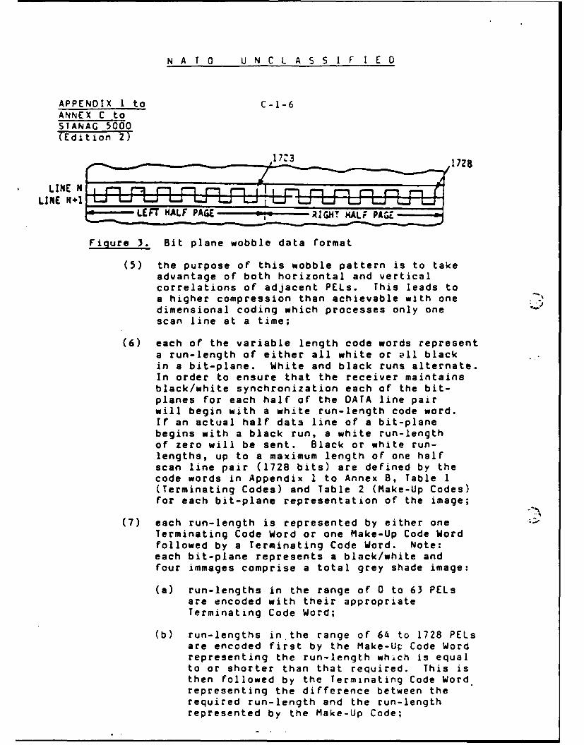
N A T 0 U N C L A SS I F I E D
APPENDIX I to C-1-6ANNEX C toSTANAG 5000(Edition 2)
1773 17Z8
LINE NLINE N J L"
r ... LEFT HALF PAGE -- RIGHT HALF PAGE
Figure 3. Bit plane wobble data rormat
(5) the purpose of this wobble pattern is to takeadvantage of both horizontal and verticalcorrelations of adjacent PELs. This leads toa higher compression than achievable with onedimensional coding which processes only onescan line at a time;
(6) each of the variable length code words represent
a run-length of either all white or all blackin a bit-plane. White and black runs alternate.In order to ensure that the receiver maintainsblack/white synchronization each of the bit-planes for each half of the DATA line pairwill begin with a white run-length code word.If an actual half data line of a bit-planebegins with a black run, a white run-lengthof zero will be sent. Black or white run-lengths, up to a maximum length of one halfscan line pair (1728 bits) are defined by thecode words in Appendix I to Annex 8, Table 1(Terminating Codes) and Table 2 (Make-Up Codes)for each bit-plane representation of the image;
(7) each run-length is represented by either oneTerminating Code Word or one Make-Up Code Wordfollowed by a Terminating Code Word. Note:each bit-plane represents a black/white andfour immages comprise a total grey shade image:
(a) run-lengths in the range of 0 to 63 PELsare encoded with their appropriateTerminating Code Word;
(b) run-lengths in the range of 64 to 1728 PELsare encoded first by the Make-Up Code Wordrepresenting the run-length which is equalto or shorter than that required. This isthen followed by the Terminating Code Wordrepresenting the difference between therequired run-length and the run-lengthrepresented by the Make-Up Code;

N A T 0 U N C L A S S I F I E D
C-1-7 APPENDIX I toANNEX C toSTANAG 5000
(Edition 2)
(b) Auto Resolution: Means shall be provided to implementa half (low) resolution function (on a selected bit-plane basis) to increase the achievable compressionby taking advantage of the fact that not all regionsof'a grey scale image contain high resolution
* information. Lower order bit-planes have littleeffect on the perceived resolution and as aconsequence may be transmitted at lower resolutionin regions of slow intensity variations. Bit-planeactivity is determined and low resolution operationis automatically implemented on a half scan linepair (bit-plane) basis when the number of transitionsof a given bit-plane (Table 3) is less than 60.
S.NOTE: The number of transitions is not an issue of inter-operability and a threshold of sixty is a suggestedimplementation number.
(1) Auto Resolution Algorithm - when half resolutionprocessing is selected, a majority logic derisionwill take place for each bit-plane group of
four bits (L11, L12, L21, L22, etc.) being readin prior to run-length encoding to create asingle bit which represents the average of thefour bits:
(a) transmitter: perform a majority logicdecision such that if 3 or 4 bits are"black", substitute a black bit for thegroup of four. If zerol or 2 bits are"black" substitute a white bit for thegroup of four;
- (b) receiver: expand each "black" data bit or"white" data bit received into four identicalbits prior to data recording;
Table 3. Bit-Plane vs. Auto Resolution Punction
Auto Resolution Algorithm
3it Plane 16 Grey Shades a Gre Shades, 4 Grey Shades
I (MSBP) not invoked not invoked not invoked
2 automatic decision automatic decision automatic decision
3 automatic decision" automatic decision" discard
4 (LBP) low resolution discard discard
always invoked
If bit-plane 2 automatically has selected majority logic
processing (for a half scan line pair) bit-plane 3 shall providemajority logic processing regardless of threshold test.
C-1-7
N A T 0 U NC L A S S I F I E D
m mmmmm | mmImm

N A T 0 U N C L A 5 S I F I E D
APPENDIX I to C-i-8ANNEX C toSTANAG 5000(Edition 2)
(2) Siqnalling of Auto Resolution Mode; autoresolution processing must be specifiedto the receiving unit on a half scan linepair basis by preceding each half scanline pair with one of the following 3 bitcodes of Table 4.
Table 4. Auto Resolution Signallinx Codes
16Grey Shades '3 Grey Shades 4 Grey Shades-Code Meaning Code Meaning Code Meanng
110 MM 110 ,im - -
100 iolo 100 HJ 100 -400 LL000 alL 000 HL
BPXI
. - Higb ResolutionL - Low Resolution
--
If the first bit (as a consequence of majoritylogic decision) of a half scan line pair bit-plane .is black, a white run-length of zero will besent prior to coding the half line pair of that Jbit-plane.
(c) Beqinning-of-Line Pair (BOLP); these code words precedeeach line pair of coded data (Figure 1) and are unique Q,code words that can never be found within a valid halfline pair of coded data. Therefore, resynchronization -after an error burst is possible: 0BOLP Format: O00O00000000000l1..
(d) Beginning-of-Intermediate (Half Line) Pair (BLP);these words precede each (right half page) half linepair of data (Figure 1) and are unique code wordsthat can never be found within a valid half linepair of coded data. Therefore, resynchronizationafter an error burst is possible:BILP Format: 00000000000000011.
(e) Fill; a pause may be placed in the message flow bytransmitting FILL. FILL may be inserted between aline pair of DATA and a 8OLP but never within thebit-planes. FILL must be added to ensure that eachline pair of DATA, FILL, BOLP and handshake SOM .7(when set) exceeds the minimum transmission time of Ua total scan line pair established as 40 milliseconds(Figure 1). The maximum length for a single line pair/of FILL is 5 seconds. After this the receiver may J

N A T 0 U N C L A S S I F I E 0
C-i-9 APPENDIX 1 to
ANNEX C toSTANAG 5000(Edition 2)
(f) Return to Control (RTC); the end of the documenttransmission is indicated by sending a minimum oftwo RTCs. Each RTC shall consist of six consecutiveEOLs. Following the RTC signals, the transmitterwill send the post-message commands.
RTC Format: 000000000001 000000000001EOL 1 EOL 6
16. Compressed with FEC. Since each bit-plane of a greyscale image is in itself a black and white image, the channel-coder, bit interleaving buffer and synchronization of items 7through 12 of Appendix 1 to Annex B applies.
C-1-9
NAT O U N C L A S S I F I ED

N A T 0 U N C L A S S I F I E D
APPEDIX I to C-I-10ANNEX C toSTANAG 5000(Edition 2)
Auto resolution 3 bit word(Table 4)
)4 X, M PI Eoq PA EoLI P4 .I BIL A AX I P11 EoLI P21 EoL P ED P"
NOTE: P1 M0 P4 REPRESNT BIT PLANEWOBBLE DATA ENM HALF SCAN LINEPAIR N r HALF SCAN LINE PAIR N+lCOMRSED AS VARIABLE LUCI
STAR OF CODE
DATA
.OLPI LINE PAIR DhTA BOLP I LINE PAIR ATA FILL BOLP
NOTE: T - MINIMUM TRANSMSSIN TIME OF A WrTAL SCAN LDJE PAIRBILP n BGIIING OF INTRMEIATE LINE PAIRBOLP a BE;INNIG OF LIN PAIR
Figure 1. Example for an enced scan line pair of 16 gre, shades startingat the beginning of a page
DATA BLP D A I O',. o s ! ST-MESS,,E(Each consisting ot sm
EOLs)
Figure 2. Ecample for an encoded scan line pair showing the last scan linepair of a page
C-1-l
N A T 0 U N C L A S S I F I E 0

N A T 0 U N C L A S S I F I E D
C-2-1 APPENDIX 2 toANNEX C to
STANAG 5000(Edition 2)
SIGNALLING PROTOCOLFOR THE NATO MANDATORY MODES
INTRODUCTION
I. The selection of the parameters used for each trans-
mission is signalled to the receiver using Start of Message
(SOM) frames and the termination of the facsimile transmission
is signalled by an End of Message (EOM) sequence.
2. The protocol signal structure is identical to NATO
~ .. Type 1 equipment and has been specifically designed to provide
* " extremely high assurance of correct receiver operation (automatic
start, mode setup and automatic stop) in error environments as
high as 10-2 bit error rate (BER). This means that a return
acknowledge is not necessary for the mandatory mode which
simplifies operation.
3. The design of the SOM allows for non-mandatory or
alternative, operation modes and is covered in Appendix 3.
PROTOCOL SIGNAL DESCRIPTION
4. Synchronization Code Words. The synchronization code
words to be used for NATO Type 2 equipment are identical to the
words used for NATO Type I equipment. A definition of these
words and their characteristics is described in paragraph 4 of
Appendix 2 to Annex 8.
5. Start of Message (SOM). Each SOM frame consists of two
pairs of synchronization code words Sl/SO, separated by an
-* interval.
SON frame format I 1 S~ IIx clock periods Sl0
6. The mode is indicated by the number of clock periods (X)
between the two pairs of synchronization code words. The 18
values of X to be denoted the mandatory interoperability modes
are shown in Table I along with the corresponding 8 bit binary
designators.
7. The number of clock periods (X) transmitted during the
interval between the two pairs of code words indicates the
operating mode. The data bit corresponding to each of the clock
periods shall be logic ones.. The SOM frame is transmitted three
C-2-1
N A T 0 U N C L A S S I F I E D

N A T 0 U N C L A S S I F I E D
APPENDIX 2 to C-2-2ANNEX C toSTANAG 5000(Edition 2)
times but detection of any one frame is sufficient. Use of thesesignals is described in paragraph 9, Signalling Sequence andTiming. Values of X for optional modes are given in Appendix 4,Protocols for Optional Modes.
8. End of Message (EOM). EOM consists of at least 16 Scode words transmitted in sequence. When four consecutive SIcode words have been detected, EOM is declared. This procedureis identicial to NATO Type 1 equipments.
SIGNALLING SEQUENCE AND TIMING
9. The sequence and timing for the compressed mode withand without FEC and the uncompressed mode is identical toparagraph 7 through 9 of Appendix 2 to Annex B.
C- 2- 2

. 0 C-c C-0 0 -c I -
W0 -iC O- 00 0 - -
CLZC a -0- -- ' 0000--- --- - - -- - --- ------- --- 0---- - -- 0000
oJ-4 -
0000 0 00 -, 'i_, .,
:0l-4 l
01 1%1C, 0 or4 o 0 q o e- ...4 to
'",._00,0 0000 0000 !.0000 -. ,.
-----------------------------------------------------------
,-1
I& U
-- -
A-J
- - - -
----------------------- -------------------

IN AI
NATO UNCLASSIFIlED
APPE\DIX 3 to C-3-I
A N\E C toST %AG 5000(Edition 2)
OPTIONAL IMAGE PARAMETERS
1. Optional image modes are: 3.85 lines per mm in thevert~cal directian and 864 elements per scan line, for 2, 4, 8and 16 grey shades.
2. Image data coding of these optional modes is coveredin Appendix 1.
NOTE: The maximum number of PELs per half line pair in thesemodes is 864 elements.
3. The signalling of these optional modes is covered in
Appendix 4, Protocols for Optional Modes.
C-3-L
N ATO0 U NCL A SS IF I ED

N A T O U N C L A S S I F I E D
C-4-1 APPENOIX 4 toANNEX C toSTANAG 5000(Edition 2)
PROTOCOLS FOR OTPIONAL MODES
INTRODUCITON
1. In addition to the optional image parameters definedin Appendix 3, it is necessary to identify certain optionaloperating modes:
(a) handshake mode;
(b) extended protocol.
OPTIONAL IMAGE PARAMETERS
2. The signalling of the optional resolution modes iscontrolled by bits 3 and 4 of the COMMAND SOM as shown inFigure 1.
HANDSHAKE MODE
3. The handshake mode protocol is identical to paragraph 5of Appendix 4 to Annex B.
EXTENDED PROTOCOLS
4. The procedure for extended protocols is described inAppendix 5 to Annex B.
C-4-1
N A T 0 U N C L A S S I F I E D

0 0
U 0. )
00
CL Zi <CL Z. P-
00wrJd 0
4~v I..J~W 2- - 4A.- - -j Co
Cc a
JZi 0. -W
cc K
&A. 4A w oc zzw 4
= =--' -j 0- h 6- -m-0JMUl
- x
zi 30-C4
0ALa oI
C-4-2