ii ii - abb ltd · pdf filedirectional comparison ground-fault protection ago3-3005 e page 3...
TRANSCRIPT

AGO3-3005E
March 1990..~ II II
ABB
Relays

AGO3-3005 E
Page 2Directional comparisonground-fault protectionABB Relays
1. IntroductionLIst of contents
2. Directional ground-fault protection2.1 RXPE 47 assembly
2.2 RAEPA assembly
3. Current and dual polarization
4. Cooperation with communicationequipment
5. Protection schemes5.1 Basic logic -permissive scheme
5.2 Basic logic -blocking scheme
5.3 Current reversallogic5.4 Weak-end-infeed logic5.5 Phase selector unit
5.6 Trip logic5.6.1 Single-phase tripping logic5.6.2 Three-phase tripping unit
6. Technical data6.1 RXPE 47
6.2 RAEPA6.3 RXIG 226.4 RXEG 21
6.5 RXPE 40
Fig.16
Fig.17
Fig. 1List of illustrations
Fig. 2
Fig.
Fig.
Fig.
Fig.
Fig.
Fig. 3
Fig. 4
Fig.5Fig. 6
Fig. 7
Fig.23
Fig.24
Fig.25
Fig.26
Fig.8
Fig.9
Fig.10
Fig.11
Fig.27
Fig.28
Directional comparison operatingprinciple
RAEPA operates when1 x cos (4-70°) >IS
RXPE 47 operating values
RAEPA operating values
Current polarization
Dual polarization
Different direction of zero- andpositive-sequence current
Basic logic permissive scheme (5.1)
Internai fault
Externa! fault
Basic logic -blocking scheme
(5.2.1 )
Basic logic blocking scheme (5.2.2)
Operating time of RAEPA andRXIG 22
Internai fault
External fault
Fig.12
Fig.13
Current reversal
Current reversal during single
phase auto-reclosing
Current reversallogic (5.3.1)
Current reversal logic (5.3.2)
Current reversal logic (5,3..3)
Weak-end-infeed logic (5.4)
Voltages and currents during phaseto ground faults
Phase selector unit (5.5)
Single phase tripping logic (5..6,1)
Three-phase trippingunit
Operating and reset (slashed) timesRXPE 47
Operating and reset times RAEPA
Operating and reset (slashed) timesRXIG 22
Operating and reset (slashed) timesRXPE 40
Fig.29Fig.14
FiQ.15
18
19
20
21
22

Directional comparisonground-fault protection
AGO3-3005 E
Page 3ABB Relays
Introduction The majority of transmission line outagesresult from faults involving ground withlightning as the principal cause.
A distance relay will operate for ground-faultsas weil as short-circuits. The capability ofdetecting very high resistive ground-faults islimited by the measuring principle used bydistance relays.
By adding a directional ground-fault relay.more than ten times as high fault resistancecan be detected. The high sensitivity (down to5% of rate d current) is achieved bymeasuring the zero sequence current.
High resistive ground-faults do not cause highfault currents. This means that relatively longfault clearing times can normally be accepted.
Two versions of directional ground-fault relayswith time delayed operation are described inBO3-3020E (type RXPE 47) and BO3-3050E
(type RAEPA).
When faster fautt clearing is required, thedirectional ground-fault relay can be used in adirectionat comparison scheme with acommunication channel. In such a schemethe ground-fault relay operates instan-taneously but is allowed to trip on ly afterreceipt of a carrier signal (when a permissivescheme is used). In this way tripping will bemade on ly for faults on the protected linesection. This is illustrated in Fig. 1.
When introducing an instantaneous ground-fault relay in the protection system, the effectof paralIei lines and single phase auto-re-closing must also be considered. This isfurther discussed in Section 5.3.
CSCRTrip
CSCRTrip
Directional comparison operating principleFig. 1
AGO3-3005 E
Page 4
Directional comparisonground-fault protection
ABB
Relays
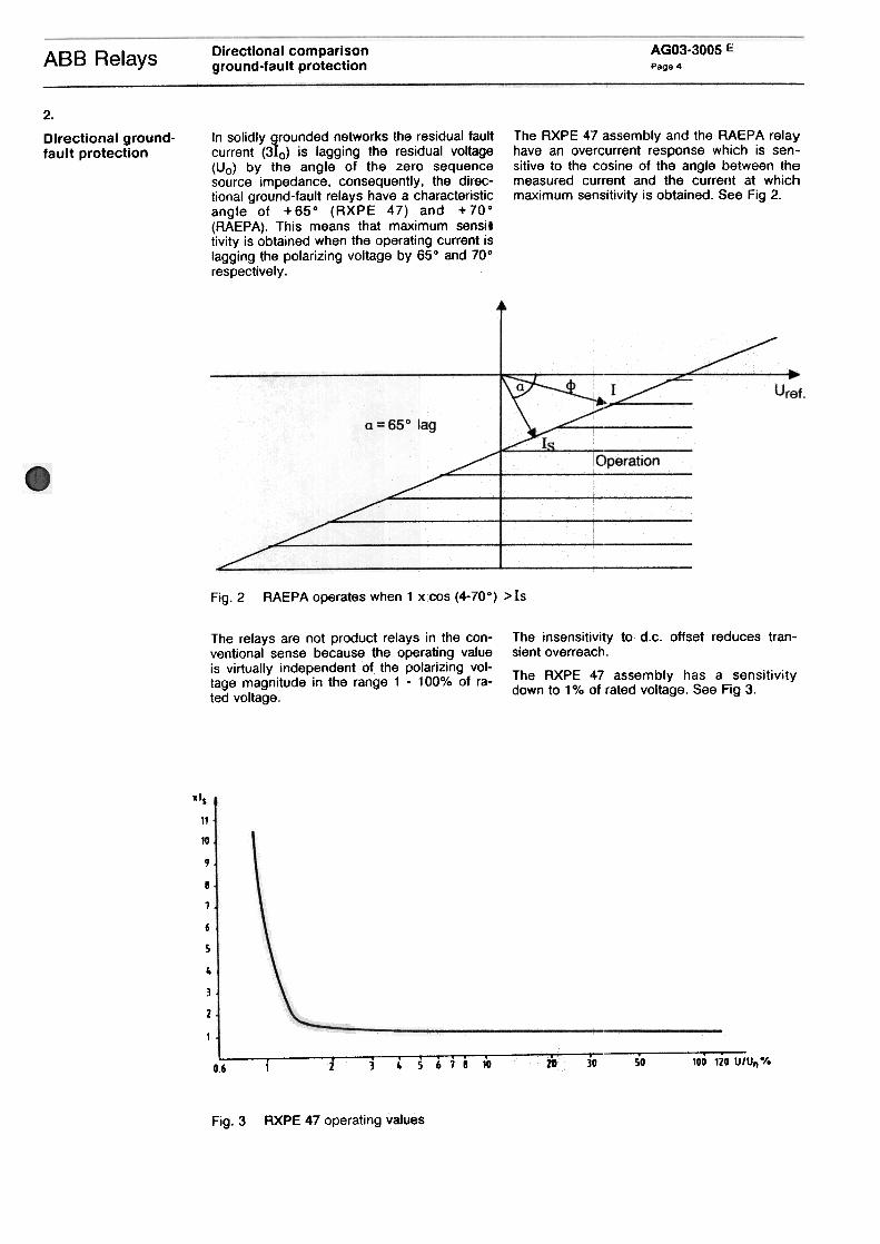
In solidly grounded networks the residual faultcurrent (310) is lagging the residual voltage(Uo) by the angle of the zero sequencesource impedance. consequently. the direc-tional ground-fault relays have a characteristicangle of + 650 (RXPE 47) and + 700(RAEPA). This means thai maximum sensiltivity is obtained when the operating current islagging the polarizing voltage by 650 and 700
respectively.
The RXPE 47 assembly and the RAEPA relayhave an overcurrent response which is sen-sitive to the cosine of the angle between themeasured current and the current at whichmaximum sensitivity is obtained. See Fig 2.
2.
Directional ground-fault protection
RAEPA operates when 1 xcos (4-70°) > IsFig.2
The relays are not product relays in the con-ventionai sense because the operating valueis virtually independent of the polarizing vol-tage magnitude in the range 1 -100% of ra-ted voltage.
The insensitivity to d.c. offset reduces tran-sient overreach.
The RXPE 47 assembly has a sensitivitydown to 1 % of rated voltage. See Fig 3.
Ils
11
10
9.
8
7
6.
5 j~ .3
2
1
...0.6 1 6 1 8 10 2Q 30 50 100 120 U/Un-/-
Fig.3 RXPE 47 operating values

Directional comparisonground-fault protection
ASS Relays AGO3-3005 E
Page 5
voltages equal to or lower than existingharmonics. we recommend the RAEPA relay.RAEPA contains harmonic filtering whichenables it to operate reliably for a fundamentalvoltage component equal to only 0.75% ofrated voltage with the simultaneous presenceof a third harmonic equal to 2% of rated
voltage.
For lower harmonic content RAEPA has asensitivity down to 0.5% of rated voltage. SeeFig 4.
For low values of residual voltage the RXPE47 relay's directional measuring properties areinfluenced by the presence of harmonics. Thethird harmonic content can be relative ly highfor CCVT's connected in broken delta. Forproper operation, the harmonic voltage shouldalways be less than the lowest fundamentalpolarizing voltage required by the RXPE 47relay.
If operation is required for residual polarizing
Fig. 4 RAEPA operating values
2.2
RAEPA assembly
The directional relay assemblies are availablein three versions. These versions aredescribed in Section 5.
All versions include directional relay RAEPA, atest switch RTXP 18 and various auxiliary andtime-delay relays, as described in Section 5.
2.1
RXPE 47 assembly
The directional relay assemblies are availablein three versions. These versions aredescribed in Section 5. Circuit diagrams areshown with only the RAEPA relay, but are alsovalid for the RXPE 47 relay; simply substitutean RXPE 47 relay for the RAEPA relay in the
diagrams.
All versions include directional relay RXPE 47,a test switch RTXP 18 and various auxiliaryand time-delay relays, as described in Section5.
3
Current and dualpolarization
The standard version of the directional relaysare voltage polarized. Du$ to the highsensitivity, down to 0.5% of rated voltage,there are very tew applica!tions where therelay would tail to operate.
The po/arizil'\9 current is taken from tlrleneutral current of a /ocal power transformerwith a grounded neutra/. The re/av should givemaximum sensitivity for 00 between theoperating current and the polarizing current asthe neutral current and the line residualcurrent are in phase, therefore, neither theRAEPA (+700) or the RXPE 47 (+650) issuitable for this purpose. An RXPE 40 with 00characteristic angle should be used instead.The polarizing current is applied over aresistor connected to the vo/tage inputs of therelay as shown in Fig 5.
The directional refays can afso be supplied forcurrent polarization.. Current polarization issuitable when the residual voltage isinsufficient, due to very low zero-sequencesource impedance.

AGO3-3005 E
Page 6Directional comparisonground-fault protectionAB B Relays
Current polarizationFig.5
In some applications, the residual voltagemay be low at certain times due to low sourceimpedance while at other times the sourceimpedance may be high. In this case a dualpolarized RAEPA can be used. The neutralcurrent and the residual voltage are then usedsimultaneously for polarizing as shown in Fig
6.
Current polarization can only be used whenthe neutral current always flows from theground into the system. Star/star transformersare not suitable for polarizing directional
ground-fault relays.
Three-winding transformers with one or morewindings delta-connected are suitable for
relay polarization.
Solidly grounded auto-transformers mayormay not be suitable. This has to be checked
for the specific application.
-
Dual poJatizationFig.6

Directional comparisonground-fault protection
AGO3-3005 E
Page 7AB8 Relays
4.Cooperation withcommunicationequipment
2. The healthy line can be tripped for a faulton the parailei line when short, paraileilines are connected to common buses.with positive and zero-sequence currenthaving different directions, as shown in Fig7
As the directional ground-fault relay works ina directional comparison scheme,communication with the remote line end is
required.
The communication channel can be usedexclusively for the directional ground-faultrelay or for both the distance relay and thedirectional ground-fault relay.
If one common channel is used for bothrelays the following must be considered:
1. 80th relays must work with the samescheme. permissive or blocking.
This can be avoided by using the reverselooking elements of the relay to block thecarrier send signal from the forward lookingelements.
3. If weak-infeed logit is used. both thedistance relays and the directional ground-fault relay should be coordinated.
Different direction of zero- and positive-sequence currentFig.7
5.
Protection schemes
5.1Basic logic -permissive scheme
When RAEPA is used in a directionalcomparison permissive scheme, it is sufficientto have on ly one forward looking directionalelement.
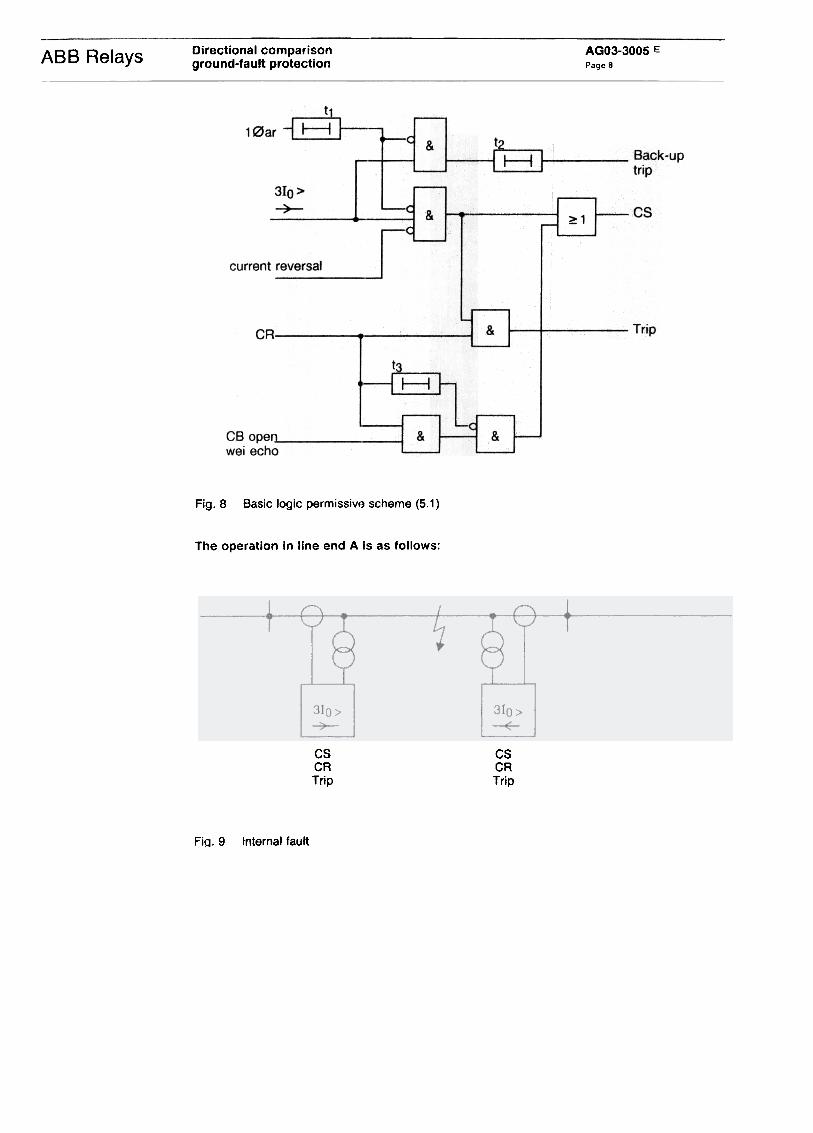
The logic is shown in Fig 8.
There are three basic schemes for thedirectional ground-fault protection. one forpermissive and two versions for blockingscheme. The basic schemes do not includetrip relays. so tri p logic should be added. Forpermissive schemes you can also add currentreversal logic and weak-infeed logic, when so
required.
A separate ph ase selector unit is available forboth permissive and blocking schemes asweil as a single phase tripping unit.
An example of how the different logics arecombined is shown in Fig 30.
Directional comparisonground-fault protection
AGO3-3005 E
Page 8ABB Relays
Fig.8 Basic logic permissive scheme (5.1)
The operation in line end A is as foliows:
CSCRTrip
CSCRTrip
Internai faultFiQ. 9

AGO3-3005 E
Page 9Dlrectional comparisonground-fault protectionABB Relays
A. Internai tault, tig 9.
1. The RAEPA relay detects a forward fault 3. If no carrier signal is received the relayand sends a carrier signal. gives a back-up trip af ter the time t2.A .. I .. d ( h settable to 0.2-3 s.
2. carrler signa IS recelve as t e remoteRAEPA also has detected a forward fault)and the breaker is tripped.
8118
1
~t3
No CSCR
No trip
CSNo CRNo trip
Fig. 10 External faut!
B. External fault, tig 10.
1. The RAEPA relay detects a forward faultand sends a carrier signal.
2. No carrier signal is received (as the remoteRAEPA has not detected any forward fault)and no instaniä"neous tripping is made.
3. If the fault persists during the time t2. aback-up trip will be made.
D. Carrier send is given by:
1. RAEPA operation as described above.
2. If a carrier signal is received and the circuitbreaker or line disconnector is open, or ifthere is a weak-infeed condition, the signalis echoed. The logic for this is included inthe scheme. The weak-infeed logic isdescribed in Section 5.4.
The carrier echo is interrupted after thetime t3. settable 0.08-1.2 seco The reasonfor this is to avoid "ringing" which meansthat aspurious carrier signal would go onbeing echoed from one line end to theother. Suitable setting is about 100 ms.
C. Operation is blocked by:
1. Start of single-phase auto-reclosing. Whenone breaker pole is open, the load currentin the healthy phases will produce a zero-sequence current that may give relay
operation.
The block remains during the time t1,settable to 60 ms -20 seco t1 should be setIonger than circuit breaker closing time +
120 ms.
If single phase auto-reclosing is not usedthe time-delay relay can be omitted.
2. Current reversals. The current reversallogic is described in Section 5..3.
AGO3-3005 E
Page 10Directional comparisonground-fault protectionABB Relays
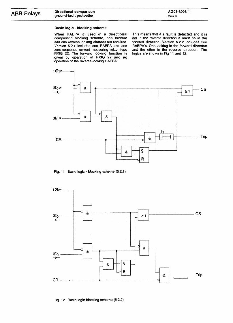
Basic logic -blocking scheme
When RAEPA is used in a directionalcomparison blocking scheme, one forwardand one reverse looking element are required.Version 5.2.1 includes one RAEPA and onezero-sequence current measuring relay, typeRXIG 22. The forward looking function isgiven by operation of RXIG 22 and !!Qoperation of the reverse-looking RAEPA.
This means that if a fault is detected and it is!!Q! in the reverse direction it must be in theforward direction. Version 5.2.2 includes twoRAEPA's. One looking in the forward directionand the other in the reverse direction. Thelogics are shown in Fig 11 and 12.
1 0ar-
310>-E-
& cs~1
& &310>
~ Trip&CR
SIR&
Fig. 11 Basic logic -blocking scheme (5.2.1)
1 0ar -
& cs310
-E-~1
~ &&
310~
s&
R
r-i~~=::j"-l.~
Trip&CR
'ig.
12 Basic logi c blocking scheme (5.2.2)

AGO3-3005 E
Page 11
Directional comparisonground-fault protection
ABB Relays
Version 5.2.2 prov ides about 30 ms fastertripping than version 5.2.1. In version 5.2.2tripping is made by RAEPA while in version5.2.1 tripping is made by RXIG 22.
See Fig 13.
Fig. 13 Operating time of RAEPA and RXIG 22
The operation in line end A is as tollows:
Fig. 14 Internai fault
A. Interna I fault, tig 14.
The RXIG 22 or the forward looking RAEPA 2. The time-delay relay t1 is timed out. Nodetects a fault. The reverse looking RAEPA carrie r signal is received as the remotedoes not operate and therefore no carrier end, reverse-looking RAEPA has notsignal is sent. detected any reverse fault. The breaker is
tripped. t1 should be set to maximumcarrier time + margin. When version 5.2.1is used, t1 should not be less than 30 ms.
Directlonal comparisonground-fault protectlon
AGO3-3005 E
Page 12
I\BB
Relays
GSNoGANo trip
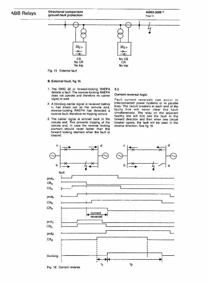
Fig. 15 External fault
No CSCR
No trip
B. External fault, tig 15
5.3
Current reversal logic
Fault current reversals can occur ininterconnected power systems or in paralIeilines. The circuit breakers in each end of thefaulty line will never clear the faultsimultaneously. The relay on the adjacenthealthy line will first see the fault in theforward direction and then when one circuitbreaker opens, the fault will be seen in thereverse direction. See tig 16.
1. The RXIG 22 or forward-looking RAEPAdetects a fault. The reverse-looking RAEPAdoes not operate and therefore no carriersignal is sent.
2. A blocking carrier signal is received beforet, has timed out as the remote end,reverse-looking RAEPA has detected areverse fault, therefore no tripping occurs.
3. The carrier signal is echoed back to theremote end. This prevents tripping of theremote end, in case the reverse lookingelement should reset faster than theforward looking element when the fault iscleared.
prota
GBa
GSa I I
I
protb
CRb
CBb
protc
csc
protd
I
I
I I IR I I C d i I I
I
I I I
!i==[========1 ~ L--: ;~ -I~ c -,blocking I I t2
I t1 I
Fig. 16 Current reversa.

Directional comparlsonground-fault protection
AGO3-3005 E
Page 13ABB Relays
Single-ph ase auto-reclosing on adjacent linescan also give zero sequence current reversalas show n in Fig 17.
Beforetripping
After single
phase tripping
310
Fig. 17 Current reversal during single phase auto-reclosing
In permissive overreach schemes. faultcurrent reversals might cause mal-operationsif steps are not taken to prevent this. Thedirectional ground-fault relay should beblocked during current reversals. This is doneby separate current reversal logic.
The current reversal logic is available in threeversions 5.3.1, 5.3.2 and 5.3.3. Which versionto use depends on the operating time of thedistance relay, carrier transmission time andcircuit breaker opening time. The limitationsregarding these times are given for eachversion below.
A ground-fault on line section 8G will be deltected as a reverse fault by the relay in 81.When the circuit breaker in 82 is opened inthe faulty phase, the load currents in thehealthy phases might give a zero-sequencecurrent that is now seen as a forward fault in81.
Fault current reversals do not have to beconsidered in blocking schemes. In suchschemes, the communication coordinationtime-delay t1, and the reverse measuringzone, prevent maloperation during faultcurrent reversals.
Version 5.3.1
The current reversal logic is built up of time-delay and auxiliary relays. Signals for carrierreceive and directional ground-fault relayoperation are taken from the basic logic 5.1.See fig 18.
Fia. 18 Current reversal logic (5.3.1)

Directional comparisonground-fault protection
AGO3-3005 EPage 14
~
Relays
The current reversal logic operates as folIows:
1. The logic allows operation of the directionalground-fault relay. provided that the carrierreceive signal has not been present duringthe time t1. before the relay operates.
2. If the carrie r receive signal comes t1before RAEPA operation. this is a currentreversal condition and the protection isblocked. The block remains until RAEPAhas been picked up during the time t2 orthe carrier receive signal disappears.
t2 should be set to carrie r reset + 30 ms.
t1 should be set according to the following:
t1 > 30 ms in order to get secure opera-tion for internai faults
t1 < shortest fault clearing time minusmaximum carrie r transmission time minus 20ms
With fast circuit breakers together with a longcarrier transmission time, it might not bepossible to set t1. Version 5.3.2 or 5.3.3should then be used.
Version 5.3.2
The current reversal logic is built up of time-delay and auxiliary relays plus a zero-sequence current measuring relay type RXIG22. The RXIG 22 relay provides a reverselooking function, the logic being that thepresence of zero-sequence current and nooperation of the forward-looking RAEPA mustmean that the fault is in the reverse direction.The signal for forward ground fault is takenfrom the basic logic 5.1. See Fig 19.
Fig. 19 Current reversal logic (5.3.2)
will operate correctly only if minimum faultclearing time (relay protection plus circuitbreaker) is Ionger than 40 ms. If the faultclearing time can be shorter, version 5.3.3should be used.
Version 5.3.3
The current reversal logic is built up of time-delay relays and auxiliary relays, plus adirectional ground-fault relay, type RAEPA,looking in the reverse direction. The signal fora forward ground-fault is taken from the basiclogic 5.1. See fig 20.
The current reversallogic operates as folIows:
1. Operation of RXIG together with nooperation of the RAEPA relay means afault in the reverse direction and thedirectional ground-fault relay is blocked.The block remains until the fauttdisappears or the forward-looking RAEPAsignal is picked up during the time t.
t should be set to carrier reset time + 30mg. RXIG 22 has Ionger operating timethan RAEPA and therefore version 5.3.2
block
(forward)
Fig. 20 Current reversallogic (5.3.3)

Directional comparisonground-fault protection
AGO3-3005 E
Page 15ABB Relays
The current reversal logic operates as folIows:
1. Operation of the reverse looking RAEPAblocks the directional ground-fault relay.The block remains during time t after thefault disappears or until the forward lookingRAEPA has operated.
t should be set to carrier reset time plus 30ms.
For version 5.3.3 there are no limitationsregarding minimum fault clearing time ormaximum carrier transmission time. as thetwo RAEPA's (forward and reverse looking)have the same operating and reset times.
In permissive schemes a separate weak-infeed logic is required. The logic providesfast fault clearance from the strong end andtripping of the local weak end circuit breakervia an undervoltage criteria.
The weak-end-logic is built up of time-delayand auxiliary relays plus undervoltage relaystype RXEG 21. The signal for forwarddirectional relay operation is taken from thebasic logic 5.1. The signal for reverse lookingrelay operation is taken from the currentreversal logic 5.3.2 (RXIG 22) or 5.3.3(RAEPA). See Fig 21. If current reversal logicis not used. a separate RXIG 22 must beadded to give this function.
5.4
Weak-infeed logic
Weak-infeed conditions can occur on aradially ted transmission line when no paralIeipath exists. The fault current infeed is thentoo low to operate the relays in the weakend.It should be noted, however, that a weak endcan in many cases be strong for phase-ground faults and weak for phase-phasefaults. as transformer neutral grounding maybe available.
In blocking schemes the strong end willautomatically be tripped during weak infeedconditions. There is no possibility to achievetripping of the weak end as no permissivesignal is sent from the strong end.
310>~ SIR~1
310>-E-
I t?
L-cj-t-1Block310>-7-
CSS
R&
CR
t1
11--1&
Trip Rw-e-i&
UR<
Trip Sw-e-i
&Us < --:i
Trip Tw-e-i&
UT<
Fig. 21 Weak-infeed logic (5.4)

Directional comparisonground-fault protection
AGO3-3005 E
Page 16ABB Relays
The weak-infeed logic operation is as folIows:
1. A carrier signal is received, indicating thatthe relay in the strong end has operated.
2. There is no start of the relays in the localweak end because the fault current is toolow.
(If there is a start from the local relays, theweak-infeed logic is blocked. The blockremains during the time t2 after the relayshave reset. t2 should be set to carrie r reset+ 100 ms).
3. A carrier echo is sent. The echo signal isinterrupted after t3 (settable 0.08-1.2 s).The time-delay relay t3 is included in thebasic logic 5.1 .
4. The directional ground-fault relay isblocked. This is to ensure thaI the relaydoes not operate due to single phasetripping of the remote line end circuitbreaker.
5. Tripping of the local breaker is made asthe voltage in the faulty phase(-s) hasdropped below the set value of the under-voitage relay RXEG 21.
6. The weak-infeed circult is reset after t1
(0.2-3 s).
The time-delay relays t1 and~ (t3 is includedin the basic logic 5.1)1 are included tominimize the effect of aspurious carrie rsignal. If a spurious signal is received. anecho will be sent (as the relays have notdetected any fault). If the other line end isalso supplied with weak-infeed logic. thesignal will be echoed the re as weil. To avoidfurther echoing of the signal the echo is sentas a pulse. the length is determined by t3;The circuit is then locke d up during the timet2. Recommended setting is t3 = 80 ms. t2 =200 ms.
If a common channel is used for the distancerelay and the directional ground-fault relay,the two relays must then have a commonweak-infeed logic. This means that the logicshould be blocked by the start of the distancerelay.
5.5
Phase selector unit
The directional ground-fault relay can be usedfor single-phase tripping and reclosing if anadditional phase selector is added. It ispossible to give phase criteria from thedistance relay but if higher sensitivity isrequired. a separate phase selector unit mustbe used.
The ph ase selector unit is built up of threedirectional relays, type RXPE 40. The basicprinciple is that for a ground-fault with highresistance, the phase angle between theneutral fault current and the related phase toground voltage is relatively small. The higherthe fault resistance. the smaller the phaseshift. See Fig 22.
URN
"'"'"/
'"
/
~
#:UgN
UTN
Fig. 22 Voltages and currents during phase to groundfaults

Directional comparlsonground-fault protection
AGO3-3005 E
Page 17ABB Relays
The RXPE 40 relays. with 00 characteristicangle. measure the neutral current and eachone has its own phase to ground voltage asreference. By using the following logic thefaulty phase is identified:
RxT=R
SxR=S
TxS=T
The logic is shown in Fig 23,
0R
&&
~1 Start R
05
&&
~1 Start S
0T&
&:2:1 Start T
Dist. prat.start
150 ms
1---11
R
s
T
Fig. 23 Phase selector unit (5.5)
The purpose of the ph ase selector unit is todetect high resistive ground-faults. For faultswith small fault resistance, close to the lineterminal, the unit might fail to give correctphase selection. The unit must therefore beused together with the phase selection from adistance relay. A start blocks the RXPE 40phase selector and the distance relay phaseselection is used for tripping. The block is
drop-out delayed 150 ms because thedistance relay might reset faster than thedirectional ground-fault relay.
The phase selector unit does not include anytripping relays or logic for three-phasetripping and should therefore be usedtogether with the single-phase tripping logicdescribed in Section 5.6.

Directional comparisonground-fault protection
AGO3-3005 E
Page 18ABB Relays
5.6
Trip logic
Two different trip logics are available. one forsingle-ph ase tripping and one for three-phasetripping.
required. from a separate phase selection unittogether with the distance relay. The phaseselection unit is described in Section 5.5.
The single-phase trip unit gives single phasetripping for single-phase faults and three-phase tripping for other types of ground-faults. It also gives three-phase tripping whenthe auto-recloser gives the signal "prepare30 trip". This will be done after a reclosinghas been made or if the auto-recloser is setfor three-phase tripping only.
The logic includes a time-delay relay that willgive three-phase tripping after the time t. for afault that is outside the reach of the phaseselectors but inside the reach of thedirectional ground-fault relay. See Fig. 24.
5.6.1
Single-phase tripping logic
The directional ground-fault relay can be usedfor single-phase tripping if a phase selector is
available.
The phase selection can be taken from thedistance relay or, if higher sensitivity is
Back-uptri p
Prepare30 trip
Trip Trip 30
StartR
Trip
R
StartS
StartT T riPT
Trip Rw-e-1
Trip Sw-e-i
Trip Tw-e-i
Fig. 24 Single phase trippil'!9logic (5.6..1)

Directional comparisonground-fault protection
AGO3-3005 E
Page 19ABB Relays
The setting of t depends on the operatingtime of the phase selectors. If the phaseselection unit described in Section 5.5 isused. t should be set to a minimum of 80 mg.
If weak-infeed logic is used. trip signals fromthis unit are also routed via the
single phase trip unit. The weak-infeed logicis described in Section 5.4.
Tripping is made by fast-acting auxiliaryrelays type RXMS 1 in paralIei with auxiliaryrelay RXME 18 with heavy-duty contacts andflag indication. Technical data for the auxiliaryrelays is found in Buyer's Guide.
5.6.2Three-phase tripping unit
The three-phase tripping unit consists of afast-acting auxiliary relay, type RXMS 1, inparalIei with an auxiliary relay, type RXME 18.with heavy duty contacts and flag indication.For back-up tripping one RXME 18 isprovided. Technical data for the auxiliaryrelays is found 1n Buyer's Guide.
If weak-infeed logic is used, the trip signalfrom this unit is also routed via the three-phase tri p unit. See Fig 25. The weak-end-infeed logic is described in Section 5.4.
Tripsignal
Tripw-e-i
ITI :
TI I: -:...}...Q--I I
I I
-I I
~ :I I
I I
I I
I
/ 0--
Tripping
I
I
I
;-!.-o,[]
Back-uptrip signal
Back-uptripping
TIIII ,~ I'I
II
..:-..}--O .I
[]
Fig. 25 Three-phase tripping unit

Directional comparlsonground-fault protection
AGO3-3005 E
Page 20ABB Relays
6
Technical data Technical data for the different measuringrelays is given below. For technical data for
auxiliary and time-delay relays, please refer toBuyers Guide.
110 V
50 or 60 Hz
10,30,100 mA, 0.3,1 or 3 A
(1-4) Kgd.c. 24, 48-55,110 .125 and 220 .250 V
1-150% ofUn
6.1RXPE 47
Rated voltage Un Rated frequency Scale factor Ks ..'..""
Current range Auxiliary voltage. Voltage range for operation
Voltage circuit:Power consumption at Un
Max Yoltage.
continuous for 1 s
4.1 VA
2.7 x Un
5.5 x Un
Current circuit
Power consumption at current = lowest setting
scale range 10-40 mA, 30-120 mA
scalerange 100-400 mA scalerange 0.3-1.2A Max current, scalerange 10-40 mA scalerange 30mA-4A
0.1 mVA
0..15mVA
0.5 mVA
continuous
2.2 A ... 1 .15A
1 s50A
350 A
24V 48/55 V .
110/125 V
220/250 V
1.0W
1.9/2.8 W
2.4/3.2 W
4.9/6.5 W
Auxiliary Yoltage circuit:Power consumption
d.c. voltage. d.c. voltage.. d.c. voltage. d.c. voltage. Permitted auxiliary voltage
deviation. -20 to + 100/,01 rated vo/tage
0.2
c
--(/)"OcouQ)(/)
.E
Q)
EF
..,
,/~
O.,
0.05
0.01.
0.03
0.02
0.0120'.3 2 3 I. 5 10
Current inmu.Jtlples of operatecvrrent
Fig.26 Operatingand reset (slashed) times RXPE.47.

Directional comparisonground-fault protection
AGO3-3005 E
Page 21ABB Relays
110VJ. 110VJ. 110 or 110VJ V50 or 60 HzReconnectable: 1 or 2 A
(0.05-0.1) Ksd.c. 48.110-125 and 220-250 V0.5-150 % of Un
6.2RAEPA
Rated voltage Un Rated frequency Scale tactor Ks Current range Auxiliary voltage. Voltage range for operation
Dependency of voltage. phase angle and harmonics
The relay operates for a current
< 2 x set current when:
U = 0.75-150% of Un
= 300 to 900 lagging
3rd harmonic of current < 20% of fundamental
3rd harmonic of voltage < 2 % of Un
5VA
1.1xUn at 16-60 Hz
3xUn at 50-60 Hz> 3xUn at 50-60 Hz
Voltage circuit:
Power consumption at
Un Max voltage.
continuously for 10 s Saturation voltage. ..
Current circuit:Power consumptionMax current.
continuously ...for 1 s
< 0.1 VA at I = Ks
15A300 A
Auxiliary voltage circuit:Power consumption
before operation,
d.c. voltage. d.c. voltage. d.c. voltage. 48V 110-125V
220-250 V
2W2.9 .4 W
5.3 .7 W
Permitted auxiliary voltagedeviation. -20 to + 10% of rated voltage

Directional comparisonground-fault protection
AGO3-3005 E
Page 22ABB Relays
Polarizingvoltoge 2 -150 8/. .Un
M-up10
2 10 'K) o
Qperating current I-cos (If -10)in multiples of set current
Fig. 27 Operating and reset times RAEPA
6.3
RXIG 22
Rated frequency
Scale factor Ks
Current range .
Auxiliary voltage
50 or 60 Hz10, 25, 50 mA, 0.1.0..25, 0.5 A
(1-3) Ksd.c. 24, 48-60, 110-125. 220-250 V
3.5 mVA
Current circuit:Power consumption atcurrent = lowest setting. Max current. n xlowest setting
continuously n = 1 s (max 350 A) n = 40
1700
Auxiliary voltage circuit:
Power consumption
d.c. voltage. d.c. voltage. d.c. voltage. 'o ..
d.c. voltage. d.c. voltage.
24 V 48/55 V .
60 V 110/125 V
220/250 V
O.5W1.4/1.8 W2.2W
3/ ,' W1;' 1.7
3.2/4.2 W
Permitted auxilia~voltage
deviation .., -20 to +10%01 rated voltage

AGO3-3005 E
Page 23Directional comparisonground-fault protectionABB Relays
Fig. 28 Operating and reset (slashed) times RXIG 22
6.4RXEG 21
Rated frequencyScale facto r KsVoltage range .
Auxiliary voltage
50-60 Hz40 V
(1-3) Ksd.c. 24, 48.60, 110-125,220-250 V
Voltage circuit:
Power consumptionOverload capacity
Continuous
15 mVA
520 V
Auxiliary voltage circuit:
Power consumption
d.c. voltage. d.c. voltage. d.c. voltage. d.c.voltage d.c.voltage ,1.2W2.1/2.8 W3.4W
2.0/2.6 W4.0/5.1 W
24 V 48/55 V .
60 V 110/125 V
220/250 V
Permitted auxiliary voltagedeviation -20 to + 10% of rated voltage
Operating time at instantaneous voltage changefrom 1.1 set value to U < Uset from1.3 from 2.5 < 55 ms
< 60 ms< 65 ms
Reset time at instantaneous voltage ch ange from U < Uset
1.1xsetvalue 1.3 x setvalue , 2.5 x set value < 30 ms
< 28 ms< 25 I1\s

Directional comparlsonground-fault protection
AGO3-3005 E
Page 24ABB Relays
110 V
50-60 Hz3. 10. 30, 100 mA, 0.3, 1 or 3 A
(1-4) Ksd.c. 24, 48-55,110-125,220-250 V
0.6-120% of Un
6.5RXPE 40
Rated voltage Un ..."".'
Rated frequency Scale factor Kg Current range.. Auxiliary voltage. Voltage range for operation
Voltage circuitPower consumption at Un
Max voltage,
continuous for 1 s
4VA
1.2 x Un
1.5 x Un
Current circuit:Power consumption at current = lowest setting
scale range 10-40 mA, 30-120 mA
scalerange 100-400mA scalerange 0.3-1.2AO,OBmVA0.12 mYA0.'4 mYA
Max current
scale range
scale range
scale rang e
continuous2.2 A 6A 15 A
1 s
50A
120 A
350 A
10-40 mA .
30-120 mA
100 mA -4 A
Auxillary voltage circuit:
Power consumptiond.c. voltage. d.c. voltage. d.c. voltage. d.c. voltage. 24V 48/55 V .
110/125 V
220/250 V
1.0 W1.9/2.8 W
2.4/3.2 W
4.9/6.5 W
Fig. 29 Operating and resel(slashed) times RXPE40
ABB Relays
ABB Relays AB, S- 721 71 Västerås, Sweden, Tel +46 21 321300
Telefax + 4621 146918; Telex 40836 abbrly s