ii - ohio pure water
TRANSCRIPT
INSTALLATION
ADDITIONAL SAFETY INSTRUCl'IONS
NOTICE: Indicates special instructions or general mandatory action.
o Read all safety hazards before installing or servicing the pump. The pump is designed for installation and service by properly trained personnel.
o Use all required personal protective equipment when working on or near a chemical metering pump.
o Install the pump so that it is in compliance with all national and local plumbing and electrical codes.
o Use the proper product to treat potable water systems, use only chemicals listed or approved for lise.
o Install the pump to work in conjunction with pool, spa, well pump, or system controls.
o Inspect tube frequently for leakage, deterioration, or wear. Schedule a regular pump tube maintenance change to prevent chemical damage to pump and/or spillage.
o Mount pump vertically and use spill recovery to run chemical back to tank in the event of tube failure.
0: Pump is not recommended for installation in areas where leakage can cause personal inju ry or property damage.
www.stenner.com II
IN STALLATI 0 N continued
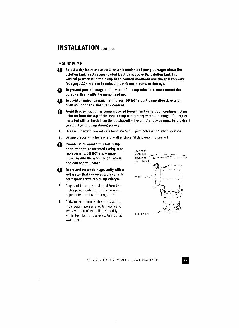
MOUNT PUMP
,0 Select a dry location (to avoid water intrusion and pump damage) above the solution tank. Best recommended location is above the solution tank in a vertical position with the pump head pointed downward and the spill recovery (see page 22) in place to reduce the risk and severity of damage.
To prevent pump damage in the event of a pump tube leak, never mount the pump vertically with the pump head up.
To avoid chemical damage from fumes, DO NOT mount pump directly over an open solution tank. Keep tank covered.
Avoid flooded suction or pump mounted lower than the solution container. Draw solution from the top of the tank. Pump can run dry without damage. If pump is installed with a flooded suction, a shut-off valve or other device must be provided to stop flow to pump during service.
1. Use the mounting bracket as a template to drill pilot holes in mounting location.
2. Secure bracket with fasteners 01 wall anchors. Slide pump into bracket.
(0 Provide 8" clearance to allow pump orientation to be reversed during tube
Rain roof replacement. DO NOT allow water (optIOnal)
intrusion into the motor or corrosion slips onto wall tHacket.and damage will occur.
"~~~:r"i,0: To prevent motor damage, verify with a volt meter that the receptacle voltage W",,,,.eM,-rii ·1 icorresponds with the pump voltage.
, '"11"' )3. Plug cord into receptacle and turn the motor power switch on. If the pump is w~~adjustable, turn the dial ring to 10. cr-·····--(
4. Activate the pump by the pump control (flow switch, pressure switCh, etc.) and verify rotation of the roller assembly
Pump Hear]within the clear pump head. Turn pump switch off.
US and Canada 800.683.2378. International 904.641.1666
i
INSTALLATION continued
ADDITIONAL INSTRUCTIONS FOR CE PUMPS
ADDITIONAL INSTALLATION INSTRUCTIONS 1. All Class II Pumps located III Zone 1 of swimming pool areas require locating where flooding cannot occur.
2. This pump is intended to be installed as "fixed" as opposed to porwble.
3. The (lain Hoof must be installed and "vertical onentation" mounting of entire unit olJserved.
4. !\tter installation, the power supply plug must be accessible during use.
5. fhls unit must be scrapped if the supply cord is damaged.
6. Ol]serve imd comply with all NatIOnal Wiring Standards.
ZUSTAZLICHE INSTALLlERUNGSANWEISUNGUN
1. f'umpen rJie sicl] in Zone 1 vom Schwilllmbecken tJefinden sollen sind so einzurichten rJa15
l.Jeberscilwelllmungen nicl]t vOrktlllllnen werden.
2. Dlese Pumpe 1st als fest montierte Ausrllstung bedacht und soli nicht umstellbar gebraucht werden.
3. Der Regendacil muss installiert werden. Eine verlikale Asnchtung der Montage rnug erzielt werden.
4. Die StrornverslJrgung mllSS nacll der Inslallierung nuctllUganglicl, scm.
5. Bei beschadlgter Verkabelung ist dioses Gerat nicl1t rnehr IU gebmucilen.
6. Staatliche VernetzungsvOIchriften rnussen eingehalten werden.
INSTRUCTIONS SUPPLEMENTAIRES D'INSTALLTION
1. Toutes les pOlllpes installees dans la Zone 1 du perimetre do la piscine doivent (\tre sltut~es de maniere a ne pas pouvoir Nre inondees.
2. Cette pompe est prevue pour installation fixe et non pas pOltatlve.
3. L:abri anti-pillie doit etre installe et I'orientation verticale doit touJours etre observee.
4. Apres I·installation. 1,1 prise etectriQue doit rester accessii)le pendant I'utilisation.
5. Celte unilrj doll dre mise au retJlIt Sl Ie corl1on declrique est endorlJJlJage.
6. Observez et adl]erez a toutes les Normes Nationales pour Installations E1ectnques.
INSTUCCIONES ADICIONALES PARA INSTALACION
1. lodi'S li1S bombas Clase II situadas en la Zona 1 (Je las aredS de la Iliscina reqUiercn colocarse donrje no
puedan ser inllndadas.
2. Esta bOl11ba es para ser instalada "fiJa" en vez de portillil.
3. Es necesano instalar f~1 tecllD rie IllIvia. y 1110lltar la ulllrJad en!r,ra sigulendo una orienlaci6n vertical.
4. Depues de la instalaci6n el enchufe sllmlnistrador de energia debe estar accesllJle durante el usa.
5. Se debera deslJechar la lInidad si el cord6n de abaslecimiento se deteriora.
6. Observe YcUilipla con talias las Heglas Nacll.lfIales para Instaiauones Uectricas.
ISTRUZIONI SUPPLEMENTARI PER L'INSTALLAZIONE
1. Tutte Ie pOlllpe Classe II localiw1te nolla Zona 1 della sllperficie circost,lIIte la piscina devono essere
collocate dove gil allagamentl no possono "Gcadere ..
2. Questa pompa, e inteso, deve essere IIJstallata come '1Issa' e non come pmtatile.
3. La tenoia deve essere installata e II montaggio 'orientazlone verticale' dell'intera unita deve essere osservato.
4. Dopo l'ins1allazione.la spina deve essere accessltiile rlur,lIlte I·uso.
5. Questa unita deve essere gettata via se il fila elettrico e danneggiato.
6. Osservare e aderire a tutte Ie Nomle Nalionali Sugli Impianti Elettric/.
www.stenner.com II
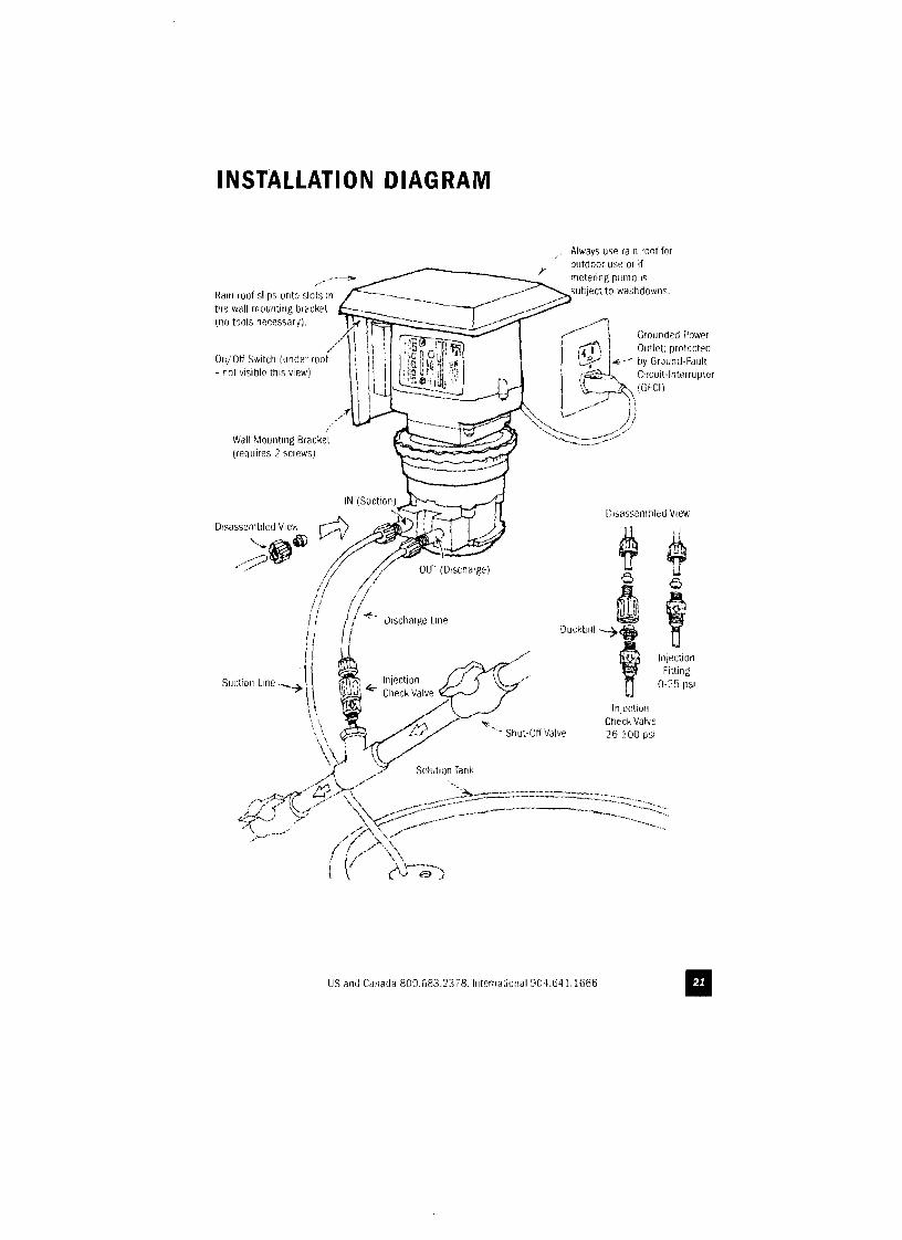
INSTALLATION DIAGRAM
Always use ralll root for outdoor use or if metering pump is subject to washdowns.Rain roof slips onto slols in
ttlC wall mounting braGkl'l (no tnols neGessary).
~ Grounded Powerr:t1'\. Outlet. protectedIi ! Li.-" I~-,~ by Ground-Fault ! '~'~ Clrcuit-IntelrupterI I, ,(GFCI)
I /"'/\..--, I
')1
"',,-, /J"-." ,/
Wall Mounting BraGket -~ (requires 2 screws)
Disassembled View
Discharge Line
Injection Fitting
0-25 psr
Injection Check Valve 26-100 psi
US and Canada 800.683.2378. International 904.641.1666 II
INSTALLATION continued
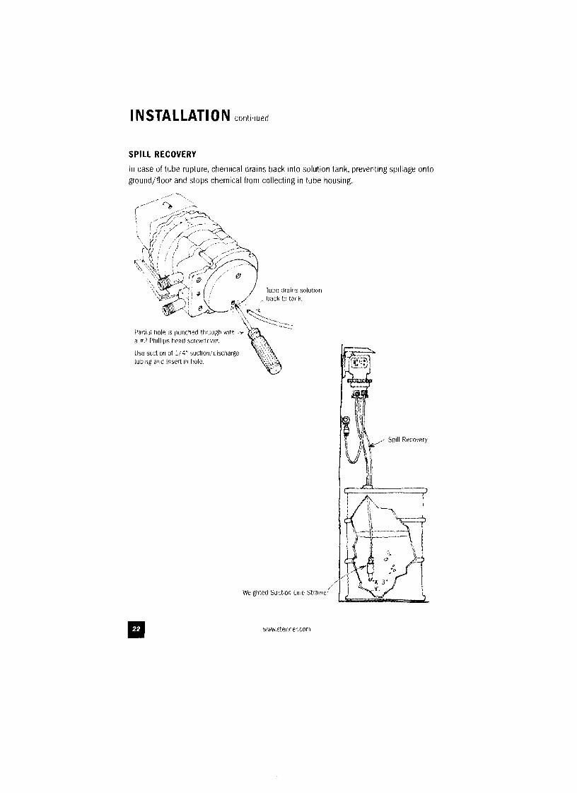
SPill RECOVERY
In case of tube rupture, chemical drains back into solution tank, preventing spillage onto ground/floor and stops chemical from collecting in tube housing.
'I
wlVw.stenner.com II
INSTALLATION continued
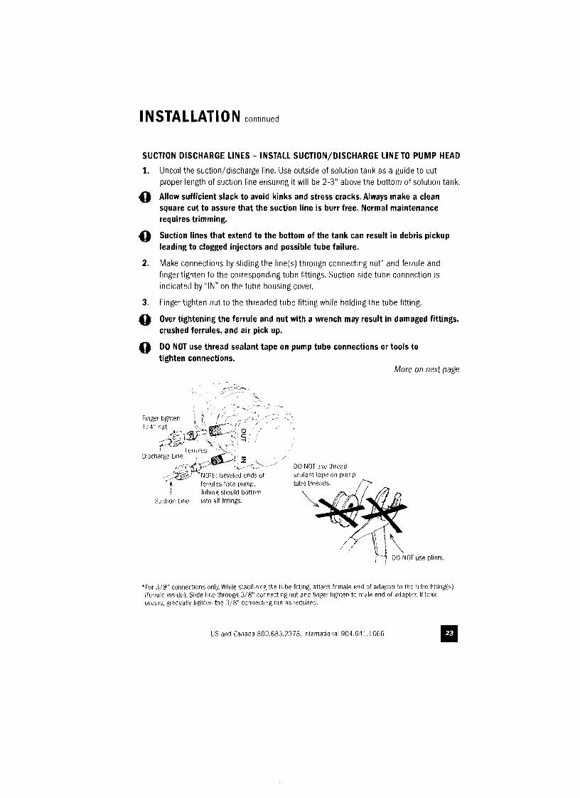
SUCTION DISCHARGE LINES - INSTAll SUCTION/DISCHARGE LINE TO PUMP HEAD
1. Uncoil the suction/discharge line. Use outside of solution tank as a guide to cut proper length of suction line ensuring it will be 2-3" above the bottom of solution tank.
,0 AI/ow sufficient slack to avoid kinks and stress cracks. Always make a clean square cut to assure that the suction line is burr free. Normal maintenance requires trimming.
;0 Suction lines that extend to the bottom of the tank can result in debris pickup leading to clogged injectors and possible tube failure.
2. Make connections by sliding the line(s) through connecting nut' and ferrule and finger tighten to the conesponding tube fittings. Suction side tube connection is indicated by "IN" on the tube housing cover.
3. Finger tighten nut to the threaded tube fitting while holding the tube fitting.
;0 Over tightening the ferrule and nut with a wrench may result in damaged fittings, crushed ferrules, and air pick up.
'0 DO NOT use thread sealant tape on pump tube connections or tools to tighten connections.
More Oil next page
"".,,/
Finger tighten ::;; -' /' ,< i . • ..>- ,< "
1/.1" nut t,' ~';-'JF'" /' , "'/';~~:;'r1V:'~;~~"'S, S
f<"~~" Ferru!es"~t:~;' Discharge L~1:;-'_'¢5:;;)~t.~ \,::>
DO NOT use thread .<::':<5i'!:.J "N[}fE: Beveled ends of sealJnt tJpe on pump .'hi ferrules fJce pump.! Tubing SllOUld bottom
Suction Line into all fittings. Wb~
/1 \I\i ;"'1 DO NOT use pliers.
'For 3/8" connectlcms only. While stalJililing the tuhe fitting. attach female end of adapter to tile tube fitting(s) (ferrule inside). Slide line through 3/8" connecting nut and finger tighten to male end of Jdapter. If leak occurs, grodl/ally tighten the 3/8" connecting nut as requirerJ.
US and Canada 800.683.237B. International 904.641.1666 II
INSTALLATION continued
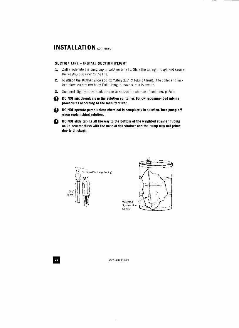
SUCTION LINE - INSTALL SUCTION WEIGHT
1. Dnll a hole into tIle bung cap or solution tank lid. Slide the tubing through and secure the weighted strainer to the line.
2. To attach the strainer, slide approximately 3.5" of tubing through the collet and lock into place on strainer body. Pull tubing to make sure it is secure.
3. Suspend slightly above tank bottom to reduce the chance of sediment pickup.
o DO NOT mix chemicals in the solution container. Follow recommended mixing procedures according to the manufacturer.
DO NOT operate pump unless chemical is completely in solution. Turn pump off0'
o when replenishing solution.
DO NOT slide tubing all the way to the bottom of the weighted strainer. Tubing could become flush with the nose of the strainer and the pump may not prime due to blockage.
\ \...:--._-
Weighted
l' Suction/DischargehJQlIlg
Suction Line Strainer
www.stenner.com II
IN STALLATI 0 N continued
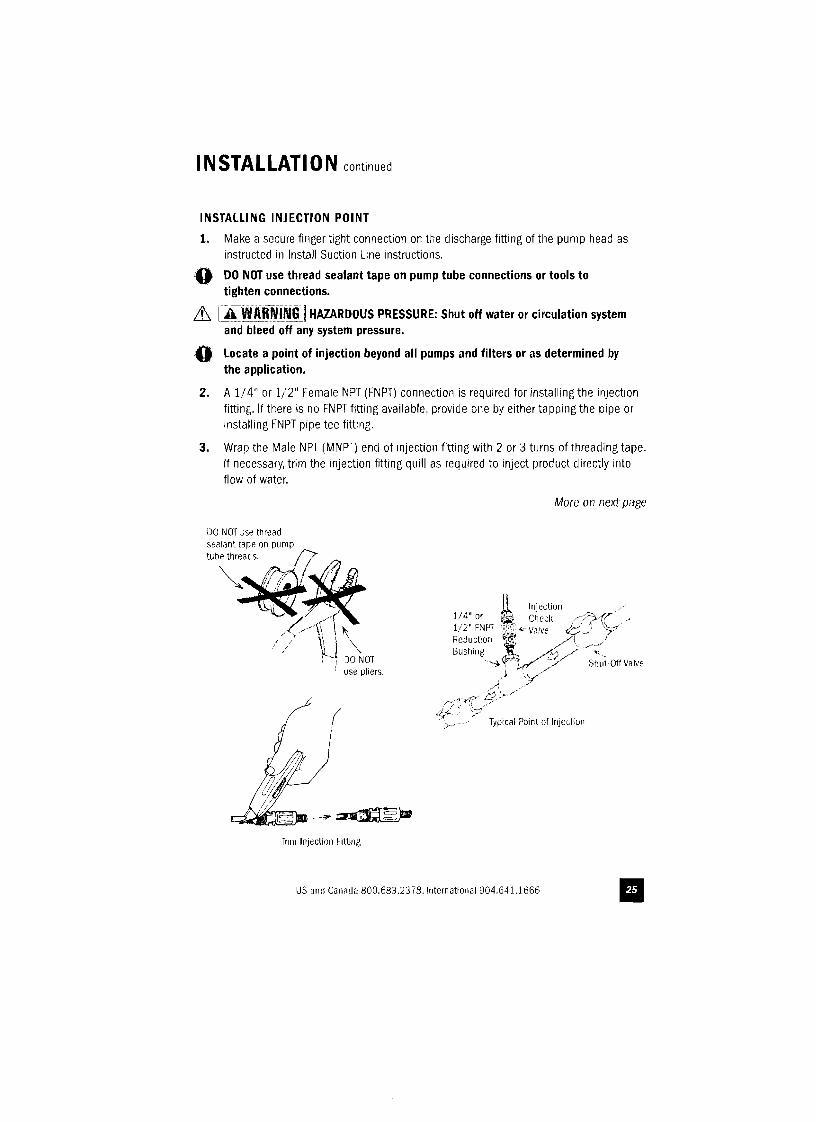
INSTAll.ING INJECTION POINT
1. Make a secure finger tight connection on the c1iscllarge fitting of the pump head as instructed in Install Suction Line instructions.
,0 DO NOT use thread sealant tape on pump tube connections or tools to tighten connections.
it, [~~l~~I~IIHAZARDOUS PRESSURE: Shut off water or circulation system and bleed off any system pressure.
,0 locate a point of injection beyond all pumps and filters or as determined by the application.
2. A 1/4" or 1/2" Female NPT (FNPT) connection is required for installing the injection fitting. If there is no FNPT fitting available, provide one by either tapping the pipe or installing FNPT pipe tee fitting.
3. Wrap the Male I'lPT (MNPT) end of injection fitting with 2 or 3 turns of threading tape. If necessary, trim the injection fitting quill as required to inject product directly into flow of water.
More 011 next page
DO NOT use thread sealant tape on pump tube threads.
i use plier5.
/IV/JtV'<=",-- ....~~
Tnm Injection Fitting
US amJ Canada 800.683.2378. International 904.6·11.1666 II
INSTALLATION continued
4. Hand tighten the injection fitting into the FNPT fitting.
0-25 psi Models (includes injection fitting)
a. Install connecting nut' and ferrule to the pump discharge tubing. Insert discharge tubing into injection fitting until it reaclles base of fitting.
b. Finger tighten connecting nut' to fitting.
26-100 psi Models (includes injection check valve)
a. Prior to connection, test injection check valve and NPT threads for leaks by pressurizing system. If necessary. tighten an additional 1/4 turn.
b. Install connecting nut' and ferrule to the pump discharge tubing. Insert discharge tubing into check valve body until it reaches base of body.
c. Finger tighten connecting nut" to fitting.
5. Turn pump on and re-pressurize system. Observe chemical flow as actuated by system and check all connections for leaks.
6. After suitable amount of dosing time, perform tests for desired chemical readings (e.g.• pH or ppm). If necessary. fine tune dosing levels by rotating dial ring (adjustable pumps only) or by adjusting solution strength.
0, The injection point and fitting require periodic maintenance to clean any deposits or buildup. To allow quick access to the point of injection, Stenner recommends the installation of shut·off valves.
'ror 3/8" connections. insert discharge tubing until If reaches base of injection fitting (25 psi) or check valve body (100 pSi). If leak occurs, gradually tighten the 3/8" connecting nut as required.
www.stenner.com II
--------------------------------
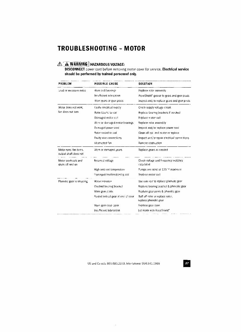
TROUBLESHOOTING - MOTOR
it. [.4:WijRNIN~]HAZARDOUS VOLTAGE: DISCONNECT power cord before removing motor cover for service. Electrical service should be performed by trained personnel only,
PROBLEM POSSIBLE CAUSE SOLUTION
Loud or excessive noise
Motor does not work;
fan does not turn
Motor runs; fan turns. output shaft does not
Motor overheats and shuts off and on
Worn ball bearings
Insufficient lubrication
Worn gears or gear posts
Faulty electrical supply
110tor bound to coil
Damaged motor coil
Worn or damaged motor bearings
Damaged power cord
Rotor rusted to call
Faulty wire connections
Obstructed fan
Worn or damagerJ gears
Incorrect voltage
High ambient temperature
Damaged/millfunctioning coil
Replace IOtor assembly
AquaShield' grease to gears and gear posts
Inspect arid! or replace gears and gear posts
Check supply voltilge circuit
fleplace bearing brackets if cracked
Replace motor coil
Replace IOtor assembly
Inspect and! or replace power cord
Clean off coil and motor or replace
Inspect and!or repair electrical connections
flernove obstruction
Replace gears as needed
Check voltage and frequency matches data label
Pumps are rated at 125" F maximum
fleplace motor call
Phenolic gear is stripping Water intrusion Use rain roof & replace phenolic gear
Cracked bearing bracket Replace bearing bracket & phenolic gear
Worn gear posts Replace gear posts & phenolic gear
Rusted helical gear at end of rotor Buff off rotor or replace rotor. replace phenolic gear
Worn gear case cover fleplace gear case
Insufficient lubrication Lubricate with AquaShield'
US and Canada 800.683.2378. International 904.641.1666 II
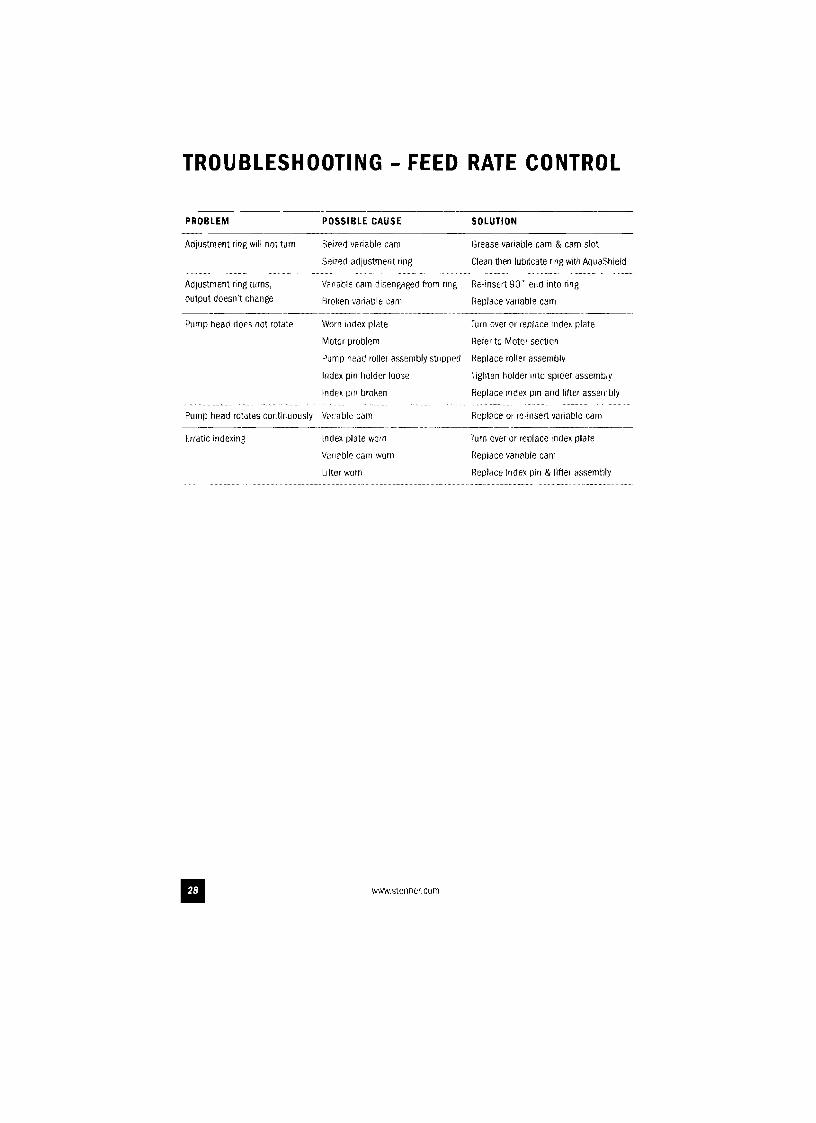
TROUBLESHOOTING - FEED RATE CONTROL
PROBLEM POSSIBLE CAUSE SOLUTION
Adjustment ring will not turn
Adjustment ring turns,
output doesn't change
Purnp head (lacs not rotate
Pump llead rotates continuously
Erratic indexing
Seized variable cam
Seized adjustment ring
Variable cam disengaged from ring
Broken variable cam
Worn index plate
Motor problem
Pump Ilead roller assembly stripped
Index pin Ilolder loose
Index pm broken
Vanable cam
Index plate worn
Variable cam worn
Ufter worn
www.stenner.com
Grease variable carn & cam slot
Clean then lUbricate ring with AquaShield
Re-insert 90' end into ring
Replace variable cam
Turn over or replace index plate
Refer to Motor section
Replace roller assembly
Tighten holder 11110 spider assembly
Replace index pin and lifter assembly
Replace or re-insert variable cam
rurn over or replace index plate
Heplace variable cam
Replace im1ex pin & lifter assembly
II
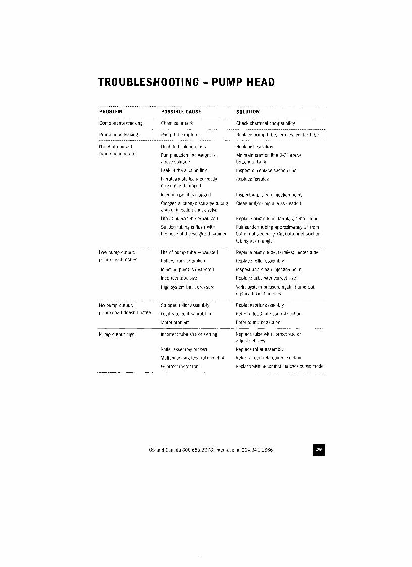
TROUBLESHOOTING - PUMP HEAD
PROBLEM POSSIBLE CAUSE SOLUTION
Components cracking
Pump IleatJ leaking
No pump output.
pump I'lead rotates
Low pump output.
pump Ilead rotates
No pump output,
pump head doesn't rotate
Pump output high
Chemical aHack
Pump tube rupture
Depleted solution tank
Pump suction line weig~rt is above solution
teak III the suction line
Ferrules installed incorrectly. missing I)r tlamagecl
Injection point is clogged
Clogged suction! dischmge tubing and/or inj(~ction c1H:~ck valve
Life of pump tube exhausted
Suction tulling is flush with the nose of the weigllted strainer
Life 01 pump tube exhausted
I~ollcrs WOrri or broke~n
Injection point is restricted
Incorrect tube size
High system back pr"ssure
Stripped roller assembly
Feelt riHe control problem
Motor problem -----,-,-----.--_.
Incorrect tube size or setting
Roller assem bly broken
Malfunctioning feelt rate control
Incorrect lIlotor rpm
Clleck cllemlcal compatitJility
Replace pump tube, ferrules; centerlulle
Replenish solution
Maintain suction line 2-3" atlove tJOltom or lank
Inspect or replace suction line
Replace ferrules
Inspect and clean injection point
Clean and!or replace as needed
fleplace pump tube. ferrules; center tube
Pull suction tubing approximately 1" from botJom of strainer! Cut bottom of suction tubing at an angle
Replace pump tube. ferrules; center tube
Heplace roller assembly
Inspect and clean injec\tOn point
Replace tube with correct size
Verify system pressure against tube psi. replace tube if needed
Replace roller assemt1ly
Hefer to feed rail' conlrol section
11efer to motor section
Replace tube witll correct size or adjust settings.
Replace roller assembly
Refer to feeel rate control section
11eplacc wittlmolor Urat nwlcttes pump model
US and Canada 800.683.2378.lntematlOnaI904.641.1666
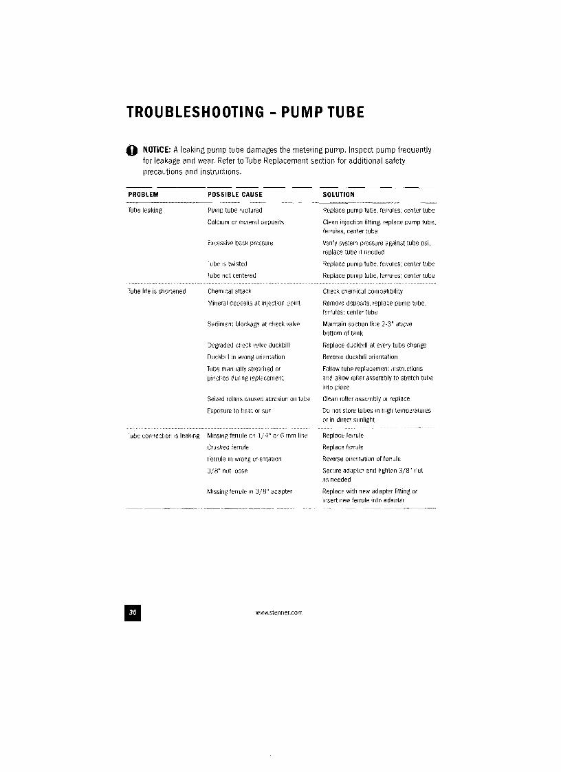
TROUBLESHOOTING - PUMP TUBE
o! NOTICE: A leaking pump tube damages the metering pump. Inspect pump frequently for leakage and wear. Refer to Tube Replacement section for additional safety precautions and instructions.
PROBLEM POSSIBLE CAUSE SOLUTION
Tube leaking
Tube life is shortened
Tube connection is leaking
F'ump tube ruptured
CalCium or mmeral depOSits
Excessive back pressure
TUbe is twisted
Tube not centered
Chemical attack
Mineral deposits at injection point
Sediment blockage at check valve
Degraded check v~lve duckbill
Duckbill in wrong orientation
Tube manually stretclleC! or pinched dunng replacement
Seized rollers caused abrasion on tube
Exposure to heat or sun
Missing fenule on 1/4" or 6 mmline
Crushed ferrule
Ferrule In wrong onentatlon
3/8" nut loose
Missing fenule in 3/8" ad~pter
www.stenner.com
Repl~ce pump tube. ferrules; center tUbe
Clean injection flttmg, replace !)ump tube, felrules; center tube
Verify system pressure ag,linst tube psi, replace tube if needed
Repl~ce pump tube. ferrules; center tUbe
Replace pump tube, ferrules; center tube
Check chemical compatibility
Remove deposits, replace pwnp tube. ferrules: center tUbe
Maintain suction line 2-3" above bottom of tank
Replace duckbill at every tube change
Reverse duckbill orientation
Follow tube replacement instructions and allow roller assembly to stretcl1 tube Into place
Clean roller assembly 01 replace
Do not store tubes in high temperatures or in direct slmlight
Replace JerruJe
Replace ferrule
f~everse orientation of ferrule
Secure adapter and tighten 3/8" nut as needed
Replace with now adapter fitting or insert flew ferrule into adapter
II
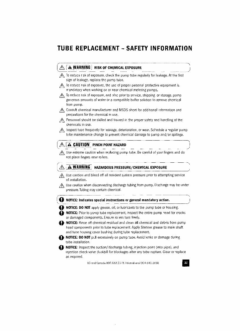
TUBE REPLACEMENT - SAFETY INFORMATION
& i~~~~~I~i:(] RISK OF CHEMICAL EXPOSURE
& To reduce risk of exposure. check the pump tube regularly for leakage. At the first sign of leakage. replace the pump tube.
& To reduce risk of exposure, the use of proper personal protective equipment is mandatory when working on or near chemical metering pumps.
& To reduce risk of exposure, and also prior to service, shipping, or storage. pump generous amounts of water or a compatible buffer solution to remove chemical from pump.
& Consult chemical manufacturer and MSDS sheet for additional information and precautions for the chemical in use.
& Personnel should be skilled and trained in the proper safety and handling of the chemicals in use.
& Inspect tube frequently for leakage, deterioration, or wear. Schedule a regular pump tube maintenance change to prevent chemical damage to pump and/ or spillage.
~"~~~ngJt PINCH POINT_~AZA~~ __.. "".. J it. Use extreme caution when replacing pump tube. Be careful or your fingers and do
not place fingers near rollers.
(it. r-AWA8nr~~Gl HAZARDOUS PRESSURE/CHEMICAL EXPOSURE l it. Use caution and bleed off all resident system pressure prior to attempting service
of installation.
it. Use caution when disconnecting discharge tubing from pump. Discharge may be under pressure. Tubing may contain chemical.
LO' NOTICE: In~icates special instructions or gene~al ma~datory ~cti~n_. _. )
0' NOTICE: DO NOT apply grease, oil, or lubricants to the pump tube or housing.
0' NOTICE: Prior to pump tube replacement, inspect the entire pump head for cracks or damaged components. Ensure rollers turn freely.
'OJ NOTICE: Rinse off chemical residual and clean all chemical and debris from pump .' head components prior to tube replacement. Apply Stenner grease to main shaft
and tube housing cover bushing during tube replacement.
:Oi NOTICE: DO NOT pull excessively on pump tube. Avoid kinks or damage during . tube installation.
,0. NOTICE: Inspect the suction/discharge tubing, injection point (into pipe), and injection check valve duckbill for blockages after any tube rupture. Clear or replace as required.
US and Canada 800.683.2378. International 904.641.1666 II
TU BE REPLACEM ENT continued
PREPARATION
1. Follow all safety precautions prior to tube replacement.
2. Prior to service, pump water or a compatible buffer solution through the pump and suction/ discharge line to remove chemical and avoid contact.
3. Turn pump off.
4. Disconnect the suction and discharge connections from pump head.
5. Plug power cord into constantly energized, properly grounded receptacle for service.
www.stellneLcom II
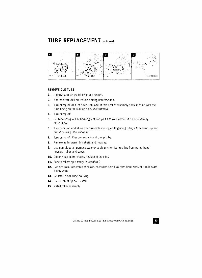
TU BE REPLACEM ENT continued
REMOVE OLD TUBE
1. Remove and set aside cover and screws.
2. Set feed rate dial on the low setting until finished.
3. Turn pump on and let it run until one of three roller assembly slots lines up witll the tube fitting on the suction side. Illustration A
4. Turn pump off.
5. Lift tube fitting out of houslllg slot and pull It toward center of roller assembly. Illustration B
6. Turn pump on and allow roller assembly to jog while gUiding tube, with tension, up and out of housing. Illustration C
7. Turn pump off. Remove and discard pump tube.
8. Remove roller assembly. shaft, and housing.
9. Use non-citrus all-purpose cleaner to clean chemical residue from pump head housing, roller, and cover.
10. Check housing for cracks. Replace if cracked.
11. Ensure rollers spin freely. Illustration 0
12. Replace roller assembly if: seized, excessive side play from bore wear, or if rollers are visibly worn.
13. Reinstall clean tube housing.
14. Grease shaft tip and install.
15. Install roller assembly.
US and Canada 800.683.2378.lnternatiollal 904.641.1666 II
TU BE REPLACEM ENT continued
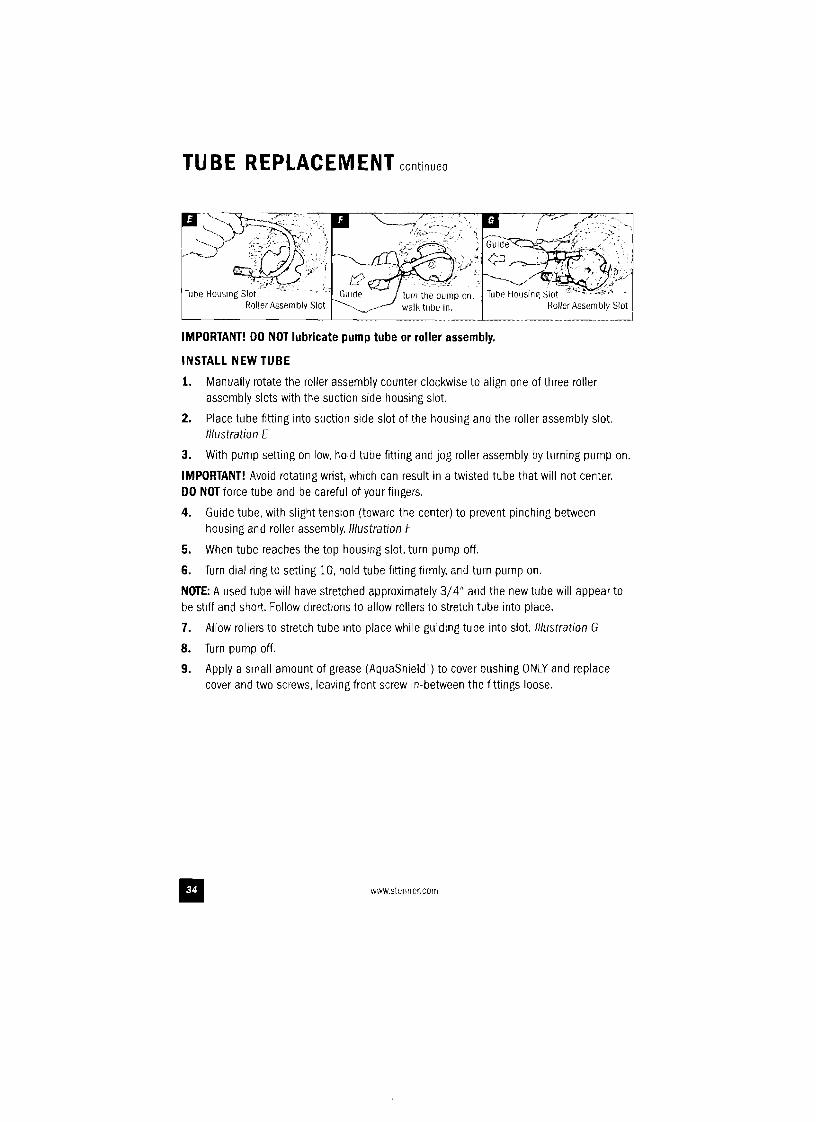
IMPORTANT! DO NOT lubricate pump tube or roller assembly.
INSTALL NEW TUBE
1. Manually rotate the roller assembly counter clockwise to align one of three roller assembly slots with the suction side housing slot.
2. Place tube fitting into suction side slot of the housing and the roller assembly slot. lIIustratiolJ E
3. With pump setting on low, hold tube fitting and jog roller assembly by turning pump on.
IMPORTANT! Avoid rotating wrist, which can result in a twisted tube that will not center. DO NOT force tube and be careful of your fingers.
4. Guide tube, with slight tension (toward the center) to prevent pinching between housing and roller assembly. Illustration F
5. When tube reaches the top housing slot, turn pump off.
6. Turn dial ring to setting 10, hold tube fitting firmly, and turn pump on.
NOTE: A used tube will have stretched approximately 3/4" and tile new tube will appear to be stiff and shall. Follow directions to allow rollers to stretch tube into place.
7. Allow rollers to stretch tube Into place while guiding tube into slot. Illustration G
8. Turn pump off.
9. Apply a small amount of grease (AquaShield') to cover bushing ONLY and replace cover and two screws, leaVing front screw in-between the fittings loose.
www.stenner.com II
TUBE REPLACEMENT continued
L..-. -'-- ~_-_' _
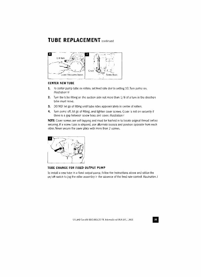
CENTER NEW TUBE
1. To center pump tube on rollers, set feed rate dial to setting 10. Turn pump on. illustration II
2. Turn the tube fitting on the suction side not more than 1/8 of a turn in the direction tube must move.
3. DO NOT let go of fitting until tube !'ides approximately in center of rollers.
4. Turn pump off, let go of fitting, and tighten cover screws. Cover is not on securely if there is a gap between screw boss and cover. Illustration I
NOTE: Cover screws are self-tapping and must be backed in to locate original thread before securing. If a screw boss is stripped, use alternate bosses and position opposite from each other. Never secure the cover plate with more than 2 screws.
TUBE CHANGE FOR FIXED OUTPUT PUMP
To install a new tube in a fixed output pump, follow the instructions above and utilize the on/off switch to jog the roller assembly in the absence of the feed rate control. Illustration J
US and Canada 800.683.2378.lnternatiollal 904.641.1666 II