iim - marina electrical equipment - marina power supplies...
TRANSCRIPT

IIM
1
1-757-258-3939
100 Warwick Court
Williamsburg VA 23185

IIM
2
Technical Specification
>Accuracy
Better than + 1% over a range of 1.5 to 200 amperes with power factor ranging from 1 to 0.5.
Approved by California Department of Food and Agriculture Division of Measurement Standards >Voltage and Current Rating
Single and three phase models monitor up to 200 amperes at 120/240V 1Ø, 120/208V 3Ø, 480V 1Ø &3Ø, 60Hz.
>Environmental Protection
Operates in -20°F (30°C) to 140°F (60°C) temperatures.
Up to 95% (RH) Relative Humidity.
Conformal coated to protect against extreme temperature and moisture. Silicone coating working temperature -85°F to 390°F High dielectric strength of 1100 volts/mil
>Input Protection
Monitor has current limiting flameproof input resistor to protect power supply.
Equipped with TVSS to clamp transient voltage surges before monitor damage occurs.
Auto resettable MOV opens and closes to protect against high voltage spikes >Safety Protection (Optional Feature)
Monitor comes equipped with a ground fault sensor, which is designed to detect dangerous leakage-current to water or ground.
Equipped with a current transformer for measuring any differential in current flow. Compatible with single and three phase systems. Equipped with a selectable dip switch that has set points from 25mA to 100mA. Higher set points
eliminate nuisance tripping. Has an internal auto test, an external test and reset button. Has visual LED that stays illuminated until the ground fault is cleared. LED will go out when test
button is reset manually. Available with an output circuit that can be used to operate a shunt trip breaker when an
excessive ground fault is detected. >External Output
Monitor equipped with standard OPTO output to allow basic interface to other systems
Monitor equipped with an OPTO input that has the ability to read external devices that have DC pulse output, such as a (kWh) meter and water meters.
Optional LED and or shunt trip circuit for ground fault detection
Test and reset button used to reset monitor after ground fault is cleared.
>External Displays
LED output Power On (Green LED)/ CPU OK Load LED flashes when Load is present Register output drive an 12volt dc electromechanical counter Ground fault LED( Red) illuminates externally when fault is detected

IIM
3
Technical Specification >Inputs
Water consumption
Ground fault detection
Electrical power consumption(kWh) >Wireless Capability (Optional Feature)
Monitor uses wireless MESH technology that reduces issues with line of sight signal loss for monitors.
Monitor networks with the NU-CORE base station that comes with software based in Microsoft Access format.
>Reporting Capability
Monitor communicates accumulated data to the NU-CORE base station software. The NU-CORE system is connected to an office computer with a USB connector.
Monitor also sends the ground fault detection wirelessly to the NU-CORE base station software.
>Connectors
Main input Voltage connector is a dual row 8-pin 600 volt, 10amp that includes: large spacing for high
voltage and operating temperature of -40 to 105°C, fully isolated terminals, positive housing locks with
polarized connector.
Current input connector is a dual row 20-pin 600 volt that includes an operating temperature range of -40
to 105°C , fully isolated terminals and positive housing locks with polarized connector equipped with
optional current transformer, OPTO circuit, Counter circuit, GFM LED circuit and shunt trip circuit.
>Regulatory Approvals
Approved for use in California, exceeds ANSI C 12.1
Safety listed by Intertek for use in U.S. and Canada
SAMPLE MONITOR

IIM
4
WIRING DIAGRAMS
Single Element Monitor

IIM
5
WIRING DIAGRAMS
Dual Element Monitor
IIM
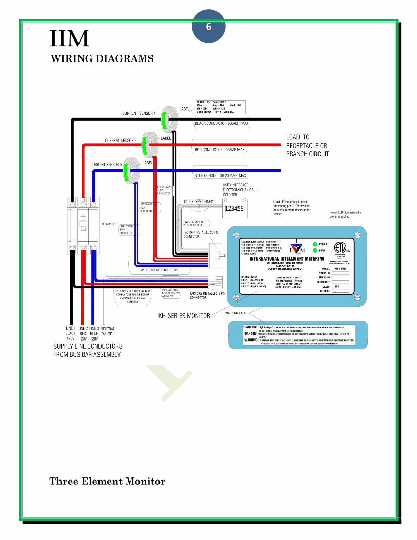
6
WIRING DIAGRAMS
Three Element Monitor

IIM
7
WIRE HARNESS ASSEMBLY
Voltage Supply Wire Harness

IIM
8
WIRE HARNESS ASSEMBLY
Current Supply Wire Harness

IIM
9
WIRELESS NETWORK
Features RF Specification
The sentinel all inclusive monitor and transceiver make for an easy install without the
need of multiple devices.
The sentinel all inclusive monitor is also a functioning standalone kWh meter.
Comes standard with up to 2 inputs that integrate existing installations to wireless.
The sentinel can upgrade from a standard monitor to a wireless mesh network protocol
The sentinel supports RF line-of-sight range up to 28 miles outdoors, using a high gain
directional antenna.
The sentinel stays idle when not receiving or transmitting data at 63mW(+18dBm) rate
at 250kbps to minimize power consumption
Each monitor is FCC certified to limit interference with existing networks.
The sentinel operates on a license-free frequency band at 2.4 GHz.

IIM
10
WIRELESS BASE STATION
Includes
Field commissioning
Software
USB Ethernet connection
SMA/NMALE cable
NMALE/NMALE antenna cable
Flat panel antenna
Nu-Core and Software Features
The Nu-Core acquisition system is a gateway to the sentinel monitors and the base station
software on the PC.
The Nu-Core supports 1000+ sentinel devices in the same network.
Wireless Operation
The sentinel network interfaces with the Nu-Core acquisition system and transmits kWh
data consumption, water consumption and potential current to ground.
The base station software collects and stores data from the Nu-Core acquisition system.
The data is accessible in a text file that updates the user’s remote billing database to
generate customer profile and billing.

IIM
11
INSTALLATION INSTRUCTION
WARNING: BEFORE INSTALLING OR WORKING ON ANY ELECTRICAL EQUIPMENT READ THE INSTALLATION INSTRUCTION IN ITS ENTIRETY.
ONLY QUALIFIED ELECTRICIANS OR CONTRACTORS FAMILIAR WITH THE CONSTRUCTION AND OPERATION OF THIS KWH MONITOR SHOULD
INSTALL THIS EQUIPMENT OR ANY ELECTRICAL DEVICE. INSTALLATION SHOULD BE DONE IN ACCORDANCE WITH LOCAL AND NATIONAL
ELECTRIC CODES.
Planning the Installation of the Monitor in Power Outlet Fittings or Panel Boards
List of materials and tools required
KH-series kWh monitor with CTs
Line voltage 4 or 8 pin connector with 18 AWG 105°C 300 volts conductors
Line current/DC 10 or 20 pin connector with 20 AWG 105°C 300 volts conductors
12volt DC electromechanical counter
Multi-meter, screw driver (Phillips and/or slotted), electrical tape, tie wraps, heat gun and screws
DISCONNECT POWER FROM THE POWER OUTLET FITTING.
Caution: Do not use the breaker in the power outlet fitting as a disconnecting means.
Disconnect must be made at the main panel or safety switch. If there is more than one
disconnect servicing the equipment disconnect both supply before servicing the
equipment.
Caution: Using a Multi-meter, check the conductors supplying power to the power outlet
for any sign of voltage. This can also be done at the receptacles at the power outlet.
INSTALLING MONITORING COMPONENTS
Note: Refer to the manufacturer’s instruction manual of the power outlet. Use the required tools to gain
access into the power outlet.
MOUNTING THE kWh MONITOR
Find the manufacturer’s recommended location inside the power outlet to mount the
kWh monitor.
With the #4 or #6 screws provided, mount the kWh monitor as shown in Figure 1 using
option 1 or 2.
FIGURE 1

IIM
12
INSTALLATION INSTRUCTION
MOUNTING THE COUNTERS (optional when counter is not provided in power outlet or panel boards)
Locate the counter’s 1/8” mounting holes for panel mount counters and/or rectangle
holes for snap-in counters
Disconnect the counter from the current supply wire harness.
Mount the counter with two #4 screws provided into the power outlet. Refer to Figure 2.
When using a snap- in counter, feed the counter conductors through the power outlet
panel from the outside. Refer to Figure 2.
FIGURE 2

IIM
13
INSTALLATION INSTRUCTION
INSTALLING MONITOR’S CURRENT SUPPLY WITH HARNESS
Locate the conductors coming from the load side of the breaker and the neutral
conductor feeding the receptacle in the power outlet or panel board.
Disconnect the conductors from the receptacle or the line conductor from the breaker
coming from the bus bar assembly. Place the current sensor between the breaker and
receptacle or between the breaker and the bus bar assembly in the power outlet. When
placing a monitor in a panel board multiple current sensors can be used on the load side
of the branch breakers to be monitored. In a case where one monitor is required, current
sensors shall be mounted on the line side of the main breaker or main lug when
provided.
Feed the load or line lead through the current sensor. (Note: The current sensor is non-
directional; it will function in any direction.) It is important to pay attention to the
phasing; if there is more than one pole or phase that will be monitored, i.e. receptacle or
breaker in the circuit, only the conductor connected to the same line voltage shall feed
through that current sensor. Refer to Figures 3-6 and pages 7 & #8 of the wire harness
assembly detail in this manual.
INSTALLING MONITOR’S VOLTAGE SUPPLY WIRE HARNESS
Connect the 18 AWG 105°C 300 volt wire from the kWh monitor voltage conductor (black,
red or blue) to the line side of breaker or to the bus bar assembly.
Connect the 18 AWG 105°C 300 volt white conductor to the neutral line at the bus bar or
to the nearest neutral conductor.
CHECKING INSTALLATION
Reconnect the gray conductors to the counter with the quick disconnect.
Check all conductors for loose connections.
Turn power back to the on position, then check that the power LED is on.
Note that when power is applied to the monitor the load LED will momentarily flash.
Apply a 1500watt load with a heat gun or equivalent for 5 minutes.
Within 2 to 5 minutes the load LED will flash, indicating a successful installation.

IIM
14
INSTALLATION INSTRUCTION
120 volt one line Single Element Monitor
FIGURE 3

IIM
15
INSTALLATION INSTRUCTION (upgrade)
Example of a unit upgrade
120/240 volt Dual Element Monitor
FIGURE 4

IIM
16
INSTALLATION INSTRUCTION
120/240 volt Two Element Monitor
FIGURE 5

IIM
17
INSTALLATION INSTRUCTION
120/208 volt Three Element Monitor
FIGURE 6

IIM
18
INSTALLATION INSTRUCTION
Monitor Enclosure
SOLID CORE CURRENT SENSOR SPLIT CORE CURRENT SENSOR
Figure 7

IIM
19