iinstallation and nstallation and mmaintenanceaintenance ... · instale soportes de pared y ganchos...
TRANSCRIPT
P/N: 098-014117-45 Rev.2 Date: 01-15-16 Drawn: TEH Checked: DMH 02-09-16 Approved: JHB 02-23-16
Installation and Installation and MaintenanceMaintenanceInstructionsInstructions
Limited One Year WarrantyEquip warrants the original purchaser (other than
for purposes of resale) that such product is free from defects in material and workmanship for a period of one (1) year from the date of purchase. During this warranty period, if the product is found to be defective, equip shall, at its option, repair and/or replace it. To obtain warranty service, products
must be returned to: Equip Foodservice Accessories Attn: Warranty Repair Department P.O. Box 1088, 2 Saddleback Cove Travelers Rest, SC 29690
Shipping, freight, insurance, and other transportation charges of the product to equip and the return of repaired or replaced product to the purchaser are the responsibility of the purchaser. Repair and/or replacement shall be made within a reasonable time after receipt by Equip of the returned product. This warranty does not cover items which have received secondary finishing or have been altered or modified after purchase, or for defects caused by physical abuse to or misuse of the product, or shipment of the products.
Any express warranty not provided herein, and any remedy for Breach of Contract which might arise, is hereby excluded and disclaimed. Any implied warranties of merchantability or fitness for a particular purpose are limited to one year in duration. Under no circumstances shall Equip be liable for loss of use or any special consequential costs, expenses or damages. Some states do not allow limitations on how long an implied warranty lasts or the exclusion or limitation of incidental or consequential damages, so the above limitations or exclusions may not apply to you. Specific rights under this warranty and other rights vary from state to state.
Attention California Residents:“WARNING: This product contains chemicals
known to the State of California to cause cancer, and birth defects or other reproductive harm.”
EQUIPADD-ONFAUCETS
Español:Instrucciones de instalación y mantenimiento
Français: Instructions pour l’installation et la maintenance
Deutsch:Installations- und Wartungsanleitungen
中文: 安装与维护说明
2
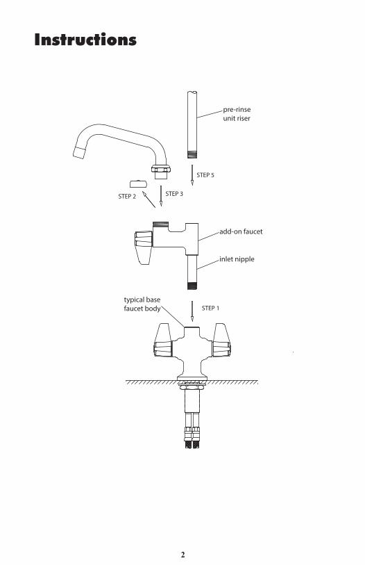
STEP 1
STEP 2 STEP 3
pre-rinse unit riser
STEP 5
inlet nipple
typical base faucet body
add-on faucet
Instructions

3
Add-On Faucet Installation:1. After installing the base faucet per its instructions, apply Tefl on tape,
Loctite, or pipe joint compound to threads of add-on faucet inlet nipple. Thread add-on faucet into outlet hole of base faucet body until joint is secure and add-on faucet body faces desired direction.
Swing Nozzle/Swivel Gooseneck Installation:Note: Silicon grease is applied to the interior swivel cavity of the body prior to shipment. No additional grease is required.2. Remove vinyl cap from body outlet.3. Insert nozzle/gooseneck into body cavity.4. Tighten swivel lock nut using 1-5/16” wrench.
Pre-Rinse Installation:5. After installation of the add-on faucet per steps 1 through 4, apply Tefl on
tape, Loctite, or pipe thread compound on the bottom of the riser. Slide fi nger hook onto riser before riser installation. While holding add-on faucet body still, thread riser into outlet hole of the add-on faucet body until joint is secured.
6. Install wall bracket(s) and fi nger hook according to instructions accompanying the pre-rinse unit.
7. Rotate spring and hose assembly until they face desired direction.8. Turn on water supplies and check for leaks.
Instructions

4
PASO 1
PASO 2 PASO 3
Tubo ascendente de la unidad prela-vado
PASO 5
Empalme de entrada
Cuerpo de grifo básico común
Grifo complementario
Instrucciones

5
Instrucciones
Instalación del grifo complementario:1. Luego de instalar el grifo básico según las instrucciones, coloque cinta
tefl ón, Loctite o compuesto para juntas de tubos en las roscas del empalme de entrada del grifo complementario. Enrosque el grifo complementario en el orifi cio de salida del cuerpo del grifo básico hasta que la unión esté fi rme y el grifo complementario esté en la posición deseada.
Instalación de boquilla giratoria/cuello de cisne giratorio:Nota: Se aplica grasa de silicona en la cavidad giratoria interior del cuerpo antes del envío. No se requiere grasa adicional.2. Retire la tapa de vinilo de la salida del cuerpo.3. Coloque la boquilla/cuello de cisne en la cavidad del cuerpo.4. Apriete la tuerca de bloqueo giratoria con una llave de 1 5/16 pulg.
Instalación de la unidad prelavado:5. Luego de la instalación del grifo complementario según los pasos 1 al 4,
coloque cinta tefl ón, Loctite o compuesto para juntas de tubos en el fondo del tubo ascendente. Deslice el gancho en el tubo ascendente antes de su instalación. Mantenga fi rme el cuerpo del grifo complementario y enrosque el tubo ascendente en el orifi cio de salida del cuerpo del grifo complementario hasta que la unión esté fi rme.
6. Instale soportes de pared y ganchos según las instrucciones de la unidad de prelavado que se incluyen.
7. Gire el conjunto de resorte y manguera hasta que estén en la dirección deseada.8. Abra los suministros de agua y revise que no haya fugas.

6
ÉTAPE 1
ÉTAPE 2 ÉTAPE 3
colonne montante du dispositif de prérinçage
ÉTAPE 5
mamelon d’admission
corps de robinet de base
robinet supplémentaire
Instructions

7
Installation du robinet supplémentaire :1. Une fois le robinet de base installé en suivant les instructions
correspondantes, appliquer du ruban de téfl on ou de la pâte à joint aux fi letages du mamelon d’admission du robinet supplémentaire. Visser le robinet supplémentaire dans le trou de sortie du corps de robinet de base jusqu’à ce que le joint soit correctement resserré et veiller à ce que le corps de robinet soit installé dans le bon sens.
Installation du bec / col de cygne pivotant :Remarque : de la graisse de silicone est appliquée à l’intérieur de la cavité du pivot du corps de robinet avant l’expédition. Ne pas ajouter plus de graisse.2. Retirer le capuchon en vinyle de la sortie du corps de robinet.3. Insérer le bec / col de cygne dans la cavité du corps.4. Resserrer l’écrou de serrage du pivot à l’aide d’une clé de 3,3 cm (1-5/16”).
Installation du prérinçage :5. Une fois le robinet supplémentaire installé en suivant les étapes 1 à 4,
appliquer du ruban de téfl on, du Loctite ou de la pâte à joint sur le dessous de la colonne montante. Enfi ler le crochet de rangement sur la colonne montante avant d’installer cette dernière. Maintenir le corps du robinet supplémentaire en place et visser la colonne montante dans le trou de sortie du corps du robinet supplémentaire jusqu’à ce que le joint soit bien resserré.
6. Installer un ou plusieurs supports muraux ainsi qu’un crochet de rangement, conformément aux instructions fournies avec le dispositif de prérinçage.
7. Faire pivoter l’assemblage ressort et tuyau, jusqu’à ce qu’ils soient installés dans le bon sens.
8. Ouvrir l’approvisionnement en eau et vérifi er l’étanchéité du dispositif.
Instructions
8
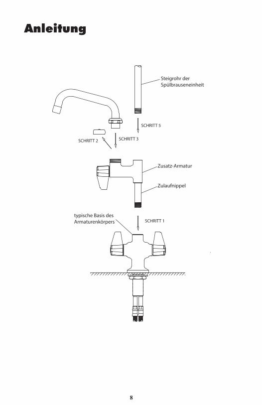
SCHRITT 1
SCHRITT 2 SCHRITT 3
Steigrohr der Spülbrauseneinheit
SCHRITT 5
Zulaufnippel
typische Basis des Armaturenkörpers
Zusatz-Armatur
Anleitung

9
Anleitung
Installation der Zusatz-Armatur:1. Nach Installation der grundlegenden Armatur nach Anleitung die Gewinde
der Zulaufnippel der Zusatz-Armatur mit Tefl onband, Loctite oder einem Fugendichtstoff für Rohrverbindungen versehen. Die Zusatz-Armatur in die Auslassbohrung des Grundgehäuses einschrauben, bis eine sichere Verbindung entsteht und die Zusatz-Armatur in die gewünschte Richtung zeigt.
Installation der Schwenkbrause/des schwenkbaren Schwanenhalses:Hinweis: Die innenseitige Schwenkbohrung im Gehäuse wird vor dem Versand mit Silikonfett versehen. Eine zusätzliche Schmierung ist nicht erforderlich.2. Die Plastikkappe von der Bohrung im Gehäuse abnehmen.3. Die Brause/den Schwanenhals in die Bohrung stecken.4. Die Überwurf-Kontermutter mit einem Schraubenschlüssel (1 -5/16”) festziehen.
Montage der Spülbrause:5. Nach der Installation der Zusatz-Armatur (Schritt 1 bis 4) die Unterseite
des Steigrohrs mit Tefl onband, Loctite oder einem Fugendichtstoff für Rohrverbindungen versehen. Den Fingerhaken vor der Installation des Steigrohres auf das Steigrohr schieben. Die Zusatz-Armatur festhalten und dabei das Steigrohr in die Auslassbohrung des Zusatzarmaturenkörpers einschrauben, bis eine sichere Verbindung entsteht.
6. Die Wandhalterung(en) und den Fingerhaken gemäß der mit der Spülbrause mitgelieferten Anleitung anbringen.
7. Die Brause mit dem Schlauch drehen, bis sie in die gewünschte Richtung zeigt.8. Die Wasserversorgung einschalten und auf Dichtigkeit prüfen.

10
第1步
第2步 第3步
预冲洗花洒直管
第5步
进水口螺纹接头
常见龙头底座
附加龙头
安装说明

11
安装说明
附加龙头安装:1.�按照安装手册完水龙头底座以后,在附加龙头进水口螺纹接头缠上特氟
龙胶带(生料带),或涂上乐泰胶水/管道胶合剂。将附加龙头安插到龙头底座的出水孔上,并调整至所需方位。
摇摆水嘴/旋转式鹅颈管安装:注意:在出厂装运前,龙头本体旋腔内壁均已涂硅油,无需再涂其他润滑脂。2.�取下附加龙头底座出水口上的塑料盖。3. 插入水嘴/鹅颈管。4. 用扳手拧紧锁紧螺帽。
预冲洗花洒安装:5. 按照第1到第4步完成附加水龙头的安装后,在直管底部螺纹处缠上铁氟
龙胶带(生料带),或涂上乐泰胶水/管道胶合剂。在安装直管前,将弯钩套在直管上,握住附加水龙头,将直管旋紧在附加龙头出水口上,直至安装到位。
6. 根据附随的花洒安装说明装好墙上支架与弯钩。7. 旋转弹簧和软管组件至所需方位。8. 打开供水开关,检查是否漏水。

12
Equip Faucet and Pre-Rinse Unit Parts List Ceramic Cartridge, Hot * 013787-45Ceramic Cartridge, Cold 013788-45Handle Screw, Plain (10) 013849-45Lever Handle Kit (includes color coded screws) 5-HDL-L3/4-27 UN Full Flow Laminar Outlet 014250-453” Rigid Gooseneck w/ Laminar Outlet 5SP-03Nut, Swivel 013839-25O-Ring, Swivel Piece (10) 013848-455-1/2” Swivel Gooseneck w/ Laminar Outlet 5SP-056” Swing Nozzle w/ Laminar Outlet 5SP-068” Swing Nozzle w/ Laminar Outlet 5SP-0810” Swing Nozzle w/ Laminar Outlet 5SP-1012” Swing Nozzle w/ Laminar Outlet 5SP-1214” Swing Nozzle w/ Laminar Outlet 5SP-1416” Swing Nozzle w/ Laminar Outlet 5SP-1618” Swing Nozzle w/ Laminar Outlet 5SP-18Check Valve, 20mm 013840-45Check Valve Adapter, 1/2” BSP 010321-45Overhead Spring, PRU 014068-45Finger Hook Assembly 004RSpray Valve Assembly, PRU 5SVBonnet Valve Assembly, PRU 002856-40Bumper, Spray Face & Screw for PRU 5SV-RKHose Assembly, 44” 5HSE44Hose Assembly, 68” 5HSE68Hose Assembly, 84” 5HSE84Hose Assembly, 96” 5HSE961/2” NPT Supply Nipple Kit (2) B-0425-M1/2” NPT Male Elbow Kit (2) B-0230-K1/2” NPT Female Eccentric Flange 00AAWall Bracket Assembly, 6” 013716-40Riser, 18” 000369-40
* Hot cartridge used in add-on faucet
Part Numbers