iiomc workshop guns for defense and...
TRANSCRIPT

IIOMC WORKSHOP GUNS FOR DEFENSE
AND RESISTANCE
THC HANDGUN
Bill Ilolmes PALADIN PRESS
BOULDER, COLORADO


TABLE OF CONTENTS
Foreword Chapter 1 Chapter 2
Chapter 3 Chapter 4 Chapter 5 Chapter 6 Chapter 7 Chapter 8 Chapter 9 Chapter 10 Chapter 11 Chapter 12
...................................................................................... 9 ............................................................. .......... Pistol Design ; 11
................................................................. The Home Workshop 17 ............................................................... Magazine Construction 23
Frame ............................................................................... 33 Receiver Assembly ................................................................... 43
.............................................................................. Barrels 57 .......................................................................... Small Parts 65
............................................... .............. Assembling And Testlng : 83 ........................................................... Hardening And Tempering 91
................................................................. Finlshlng And Blulng 99 .................................................................... Slngie Shot Design 107
................................................. Knowledge Which Might Prove Useful 123

WARNING:
It is just as illegal to build or manufacturea pistol in your own workshop for your own use as it is to build a submachine gun or any other firearm.
Therefore, be warned that you may be breaking some law if you even attempt to build either of the guns described here.
Federal law prohibits the manufacture of any firearm until, and unless, certain conditions are met.
Many state laws also prohibit firearms manufacture.
Notice From ATF P 5300.5
Title 26, United States Code No person shall make a firearm unless he has (a) filed with the Secretary or his delegate a written application, in duplicate, to make and register the firearm on the form prescribed by the Secretary or his delegate; (b) paid any tax payable on the making and such payment isevidenced by the proper stamp affixed to the original application form; (c) identified the firearm to be made in the applica- tion form in such manner as the Secretary or his delegate may by regulations prescribe; (d) identified himself in the application form in such manner as the Secretary or his delegate may by regulations prescribe, except that if such person is an individual, the identification must include his fingerprints and his photograph; and (e) obtained the approval of the Secretary or his delegate to make and register the firearm and the application form shows such approval. Applications shall be denied if the making or possession of the firearm would place the person making the firearm in violation of the Law.

Please Note:
Due to the fact that I have no control over the methods, skill, or quality of materials used in the manufactureof the weapons described in this book, I cannot assume any responsibility whatsoever for the safety or proper func- tioning of such weapons except those built by me personally.
Bill Holmes
FOREWORD
I am a bit embarrassed about the pistol designs I present here; not that they do not perform the way they were designed to-quite the contrary. These designs will perform as well as their commercial counterparts will, and are just as durable, reliable, and trouble-free. But my designs utilize the same type of stamped, brazed, and welded construction methods that gun manufacturers use to lower costs and increase production. The result is not my idea of a top-quality weapon.
The most desirable firearms are made of milled steel and wood, without use of brazed joints, castings, plastic, or alloy parts of any kind, and the custom rifles and shotguns which I build in my shop use these techniques. However, since the designs presented here are meant to be buiit in the ordinary home workshop with a minimum of tools, and quite possibly under emergency conditions, concessions have been made, both in the use of methods and materials.
While the dictionary defines a pistol as a small, hand- held firearm, there are those who would argue with my referring to a firearm as a pistol, or calling a firearm agun. These sameexperts have argued with me previously about the way I choose to label certain components of some weapons.
Well, this is my book; therefore, I feel that I can call any of the parts or components of a design of mine by any name I see fit. Those who feel otherwise would do well to come up with books of their own.
Remember, as it says on the backcover of this book, it is illegal to manufacture or own such weapons under our present laws unless the weapons are registered with the federal government.
These designs are presented then only for future use, when our survival may depend on having such weapons available.

1. Magazlne latch 2. Hammer strut 3. Hammer sprlng 4. Sear 5. Sear spring 6. Recelver retaining lug 7. Hammer 8. Flrlng pln retainer 9. Flrlng pln
10. Flrlng pin sprlng 11. Extractor sprlng and follower 12. Exlractor 13. Rear barrel retalner 14. Barrel recoil sprlng 15. Sllde body 16. Front blade slght 17. Front barrel retalner 18. Barrel 19. Takedown lock 20. Recelver retaining lug 21. Frame lug 22. Trlgger return sprlng 23. Trigger
BILL HOLMES' SEMI OR FULL 24. Dlsconnector sprlnglspring gulde
AUTOMATIC PISTOL DESIGN 25. Dlsconnectorltrigger bar 26. Ejector (behlnd dlsconnector) 27. Magazlne
Chapter One
Pistol Design
In this volume, I propose to show two different pistol (or handgun) designs which can be manufactured in the home workshop.
One of these designs is for a semi-automatic pistol, and the other describes a falling-block single shot pistol. The first one is of necessity limited somewhat by the cartridge size it must use. My second, single-shot design will handle just about any cartridge that is practical to use in a hand- held firearm, provided proper steels and heat-treatment methods are used.
While it is entirely practical to make a revolver in the home workshop if proper equipment is available, I have not included a revolver design in this book. Without pro- fessional training and equipment, it is very difficult to hand-build a revolver cylinderthat will index and lock up properly.
As with the submachine gun, probably the most difficult part to make for the semi-automatic gun is the clip or
magazine. So if possible, a suitable magazine should be obtained or manufactured first, and the frame of the gun then built around it.
The first pistol discussed here is made in .22 long rifle, .32 ACP, .380 ACP, or any combination of these three. In fact, with a magazine for each of the three calibers and a corresponding slide (barrel assembly), the same frame may be used for all three calibers. The pistol can be converted to any of the three calibers in a matter of seconds simply by turning the small take-down lever located on the left side directly in front of the trigger guard. This action releases the self-contained slidelbarrel assembly, allowing it to be lifted from the frame and replaced with a slide/barrel assembly in the desired caliber. A magazine of the corresponding caliber is inserted in the frame, and the pistol is ready to use again.
Slide and barrel assemblies made from tubing no doubt will look a little crude. And neither of these pistol designs
Rlght side vtew ot Bill Holmes' aernl-automatic plstol. bullt fn hls home workshop from Impm-
vised malerials. The gun Is cocked by meana of a palr of checkered "ears" that sre formed from the breech block's exterior.
Reverse view d the Holmes plstol. Vislble on the gun's frame are the tskedown fever [tell) and sale@. By altering this weapon'* tirlng pin and dlsconnector/ irlgger bar, Lt can be made to functlon on full automatic.
will ever be considered streamlined. But by the use of tubing in the manner described, I eliminate the necessity of cutting mating grooves along the length of both the frame and slide. Such a grooving procedure isachallenge even to the professional gunsmith with proper tools.
Nor do I normally endorse the idea of a welded sheet metal frame. My over-riding consideration here was that such a frame can be constructed with a couple of files, a hacksaw, a few drills, and a few minute's use of welding equipment. So if the design is lacking from thestandpoint of appearance, it more than makes up for it in ease of manufacture.
In the event that you elect to make this pistol with the interchangeable slide/barrel assemblies, it will almost certainly be necessary for you to manufacture your own magazines, since I do not know of any interchangeable commercial clips in all three different calibers. If you will follow the instructions in the chapter on magazine manu- facture, you should be able to make clips for the different calibers which will all fit into the same frame.
I have not incorporated a magazine safety in this design, which means that the pistol will fire with the magazine removed. When engaged, the safety lever on the left rear side of the gun blocks the hammer from contacting the firing pin. This, and a positive half-cock notch on the hammer are the only safety provisions incorporated in the pistol's design. Its firing pin is an inertia type similarto the
MI91 1 Colt .45, which allows the gun to be carried safely with the hammer down without the firing pin striking the primer of a chambered round. So the weapon may be carried safely with either the hammer down, at half cock, or at the full cock with the safety engaged.
Simple fixed sights are fastened on the top of the slide assembly. No sighting adjustment is provided since a short-barreled pocket pistol of this type is usually meant for use only at short range. The sights can be adjusted by filing the front sight to raise the point of impact in relation to the sight "picture," or by filing the rearsight sideways in the lateral direction you want to move the point of impact.
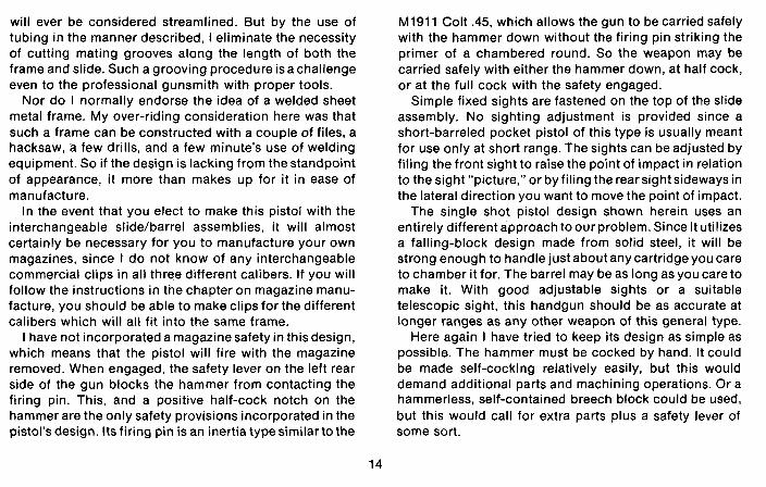
The single shot pistol design shown herein uses an entirely different approach toour problem. Since it utilizes a falling-block design made from solid steel, it will be strong enough to handle just about any cartridge you care to chamber it for. The barrel may be as long as you care to make it. With good adjustable sights or a suitable telescopic sight, this handgun should be as accurate at longer ranges as any other weapon of this general type.
Here again I have tried to keep its design as simple as possible. The hammer must be cocked by hand. It could be made self-cocking relatively easily, but this would demand additional parts and machining operations. Or a hammerless, self-contained breech block could be used, but this would call for extra parts plus a safety lever of some sort.
No attempt has been made to incorporate an ejector into this weapon. In most cases it is desirable to retrieve the empty cartridge case after firing for the purpose of reloading. So, in this design, a simple extractor actuated by the lowering of the breech block causes the spent case to protrude from the chamber farenough to begrasped by the fingers and removed. This is preferred by most shooters, rather than hunting the empty case after an automatic ejector has thrown it completely out of thegun.
I seriously recommend that your weapon be machined for rimmed cartridges. Use of a rimless cartridge compli- cates the extraction mechanism, since a spring-loaded lip is required to cam outward over the head of the case when the action is closed, simultaneously engaging the extractor groove of the cartridge case. On the other hand, the extractor for the rimmed case is of solid one-piece construction, moving only the rim of the case during ejection.
The round breech-block design shown should be used only if the gun is to be chambered for the relatively low- pressured cartridges, such as the .22 rimfires, .38 special, etc. This type is included here simply because it is much easier to build than the rectangular type also shown.
If the gun is built and chambered for any of the high pressure, high intensity cartridges such as the .22 Hornet, .357 magnum, or .44 magnum, then you must use the rectangular breech-block design. It is much strongerthan
the round one. My second pistol can also be made to accept several
interchangeable barrels in different calibers. Its caliber is changed simply by changing barrels, provided the rim diameter is the same as that of the cartridge the pistol is originally built to accept. A larger or smaller rim iameter F' will necessitate that the extractor be changed also.
I, personally, have no use for a telescopic sight on a pistol. If you want a long-range weapon, you should build a rifle. My own pistol designs utilize only adjustable iron sights, as shown in the drawings and pictures. Any "sport" who simply must have a scope on his handgun will find that scope mounts made for other handguns are also adaptable to those of my design as well.
One last word of advice: read all the instructions and study all the diagrams presented here before even con- sidering starting your home workshop gun. If you thoroughly understand all the procedures and schematics before beginning construction, your pistol will be much easier to build right the first time.
I also suggest that you have a copy of Volume One of this series handy for reference, though it is not imperative.

Chapter Two
The Home Workshop
If you have already read the first chapter of volume one of this series, the following information will already be familiar to you. Also, I realize that a good percentage of readers are amateur or professional gunsmiths, gun buffs, or machinists. To them much of this will be routine.
Very few readers will have a fully equipped machine shop at their disposal, nor all of the knowledge needed to run it professionally. Though I do have a machine shop of my own now, just a few years ago I did not. It was then that I learned most of the "home workshop" techniques I present as alternatives to making up your weapon with the help of a machine shop. Here is a list of the minimum tools necessary to build your handgun(s):
A 1/4 inch or 3/8 inch drill motor (or hand type drill) Drill bits; sizes 1/8, 3/16, 1/4, and 3/8 inch A hacksaw with several blades Several eight and ten inch flat mill bastard files
Three-cornered triangular files (small) Round files; 1/8, 3/26, and 1/4. Small square files Cold chisels; 1/8, 1/4, and 1/2 inch Center punch Scriber Micrometer or vernier caliper 12 inch ruler Protractor Appropriate taps with corresponding drills Tap wrench The use of a lathe, welding equipment, and grinder.
One of the most useful home workshop improvisations can be used to form openings or small parts usually made with a vertical milling machine. These include theejection port, trigger, hammer, sear, and many others. This substi- tute procedure is started by scribing the outline of the
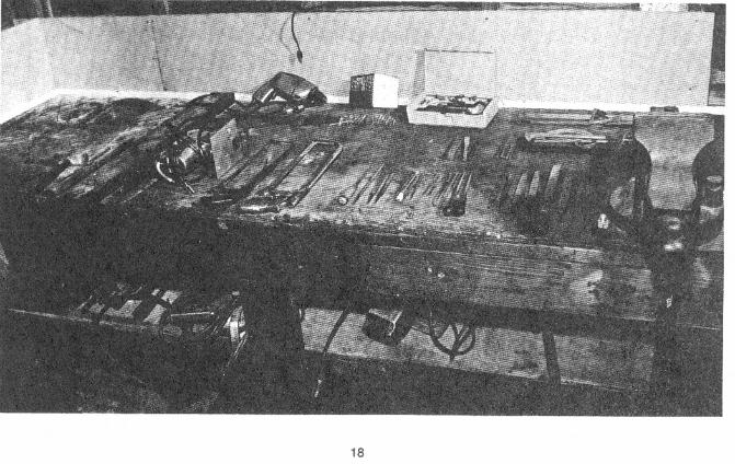

Left: here are the hand tools I use In rnaklng my home workshop guns. You Wi l l also need the use o l weldlng equipment and a lathe, If posslblm.
BY =placing the plns in the hacksaw hame with longer ones, II can be made to accommo- date two or three blades at once. Wide slots are cut far more easily with this method.
opening or part on a piece of steel of desired wldth. Drill inter-connecting holes around or with in the outline (depending on situation), until only a thin web of metal connects the outlrned area. Punch it through with a cold chisel, and finish with files.
And 1'11 add here that you should Searn to use files properly and efficiently. Many procedures normally done with a milling machine can be done with hand flies and patience, hence the fact that the file has been nick-named "the poor man's milling machine".
''The poor man's lathe," or your electric hand drilf, can be substituted for many lathe operations, but is not recommended for accuracy. Here, the part to be lathed is chucked in your drill, and the drill's handle secured in a solid vise. The drill is switched on, and a flat mill bastard file applied as shown in the photo.
All of this, and other alternative procedures covered in the following pages, add up to"jackleg"gunsmithing at its best. Patience can substitute for electricity, and perseverance for elaborate equipment. And remember, there is no reason why your home workshop gun should not be just as safe, accurate, and reliable as a similar maas- manufactured model.
Some reedsn may hnva a drill press and vice set-up llka ihls at Ihslr dlsposaT. Thone who hare only a hnnd drlll wlll have lo take extrn care to Insure that the drlll Is held at a rlghl angle to Iha work.

If no lathe Is avallabte, many lathe operations can be ped~rrned with a ~~0rIWIYettded far accuracy, 11 can save you a lot of time andsweat, and "poor man's lathe,'' as piclured hem. Though this technlque is not produce sultable results In many cases.

Theae sending dlscs were orlglnally designed to sene in
an automobile body shop. I mount such discs on an arbor, and use them lor grtndlng and
sandlng operallons. Use masonile, or a slmllar stlfl
backplate material. behind the disc.

Chapter Three
Magazine Construction
Since a proper-functioning magazine or clip is crucial to the dependable operation of the semi-automatic pistol, and is also the most difficult part to home-build, I suggest that you purchase a mass-produced magazine in the caliber desired and build the gun to fit around it.
At the present time, there are several companies that regularly advertise magazines for almost any caliber and model gun that you care to name. Most sell for eight to ten dollars. That price is considerably cheaper than you can make one for at home, if you count your time as being worth anything. If you do elect to buy your clips, get at least a couple of extras.
If an interchangeable caliber gun is planned, try to obtain magazines with the same outside dimensions in each of the calibers that you intend to use. Chances are that this will not be possible, so you must obtain magazines for the largest caliber that you intend to use,
and rebuild them to handle the smaller cartridges. For example, if you want the same pistol frame to handle the .380 ACP, .32 ACP, and .22 long rifle cartridges, you should purchase at least three identical magazines in the ,380 ACP caliber, then rebuild one or more to handle the .32 ACP cartridge, and another to accept the .22 long rifle.
In the future, the possibility exists that pre-manufac- tured magazines will no longer be available when needed, so this chapter will deal primarily with building them at home. The same method described here to adapt the magazine to the smaller calibers also applies to the conversion of existing magazines.
If you elect to make a magazine of the dimensions shown in the drawings, first obtain a section of thin sheet steel 3.200 inches wide by 3.900 inches long. It is preferable to use 22 gauge sheet metal, which is ,0299 inch in thickness, or for all practical purposes, ,030
inch thick. This .030 inch dimension is the one used throughout this chapter, so if a different thickness material is used, the forming die dimensions will have to be adjusted accordingly. If new material is not available, sheet metal salvaged from an automobile body can be used, after stripped of all paint and primer and cleaned thoroughly.
Make a template of the magazine body shown in the drawing. Transfer the outline to the sheet metal, and cut to shape with a pair of tin snips or sheet metal shears. Leave the extra material shown at the top and bottom of the center line. Locate and drill the 3/16 inch holes shown as accurately on the center line as possible. The guide pins in the forming dies fit through these to keep the blank centered while forming. Any extra metal around thesetwo holes is cut away after the magazine body is formed to shape.
Construct the male forming die from a piece of steel 4% inches long with a finished width of .380 inch and a finished depth of 1.000 inch. Its front side is rounded to a perfect half-circular contour having a radius of .I90 inch. If you cannot form this rounded portion properly, either by filing or grinding, turn a section of drill rod to the .380 inch diameter required and split it down the center. After it is filed or ground to half diameter, it is sweated or brazed to a rectangular section, thereby forming the rounded front edge.
The female die can be made in one piece, but is much easier to build in three sections. These consist of a center section .455 inch wide, an inner or top side shaped to a concave radius, and two sides welded, bolted, or riveted to the center section. The male forming die fits into the female die exactly with .030 inch clearance on each side and the front (rounded) edge. Thisallowsforthe thickness of the sheet metal blank plus another .005 inch clearance in accordance with the dimensions shown in the drawings. A 3/16 inch hole is drilled at each end of both dies exactly on center to allow for guide pins to hold both the blank and both parts of the die in the proper relationship. These two holes are drilled 3.800 inches between centers and a guide pin at least 2% inches long made for each.
Bevel the top edges of thefemaledieslightly, and polish them smooth since this surface rubs across the sheet metal as the dies are forced together. Use a press for this step if one is available. A large vise can also be used, as can a truck jack when a suitable frame is made to support it.
Coat both dies lightly with oil, and insert the guide pins into the male die. Place the magazine body blank on the pins. Once the guide pins are started into their holes in the female die, the magazine is ready to be pressed into shape. It will be necessary to place a spacer on top of the maledie slightly shorter than and between the guide pin holes to permit the male die to fully seat while clearing the guide


pins. After the male die is pressed completely into the female
die, the front and both sides of the magazine will be formed. Remove the guide pins. To form the back of the magazine body, the flaps of sheet metal left projecting above the female die must be folded over and fastened together. As shown, another three-piece die is assembled to fit over the sides of the female die. After that die is in place, swage the flaps flat against the top of the male die, and remove the male die by pushing it out of the magazine. The back is fastened together by soldering, riveting, or brazing. My own were silver soldered. The tabs for the guide pin holes are then cut off, and the lips at the top of the clip bent inward.
Cut a magazine floor-plate to shape from 1/8 inch stock. Make it long enough to extend past the front of the grip frame when it is in place. Round the plate's front edge to the same radius as the front of the magazine, and fastkn in place by silver soldering or riveting. Do not usesoft solder here! I also suggest fastening the floor plate with three 1/16 inch pins inserted in holes drilled thorugh both magazine body and floor plate and riveted in place.
Build the .22 and .32 magazines to the same external dimensions as the .380 clip, thereby insuring that they interchange in the frame. Their inside widths should be reduced to .360 inch for the .32 and .250 inch for the .22. The easiest way to do this in the home workshop is to
solder (sweat) or glue (epoxy) a spacer to the inner wall on each side to reduce its inside width to the proper dimen- sions. A template of the correct shape is included in the drawings. Also note that the lips at the top of the second two magazines must be left slightly longer so that when bent inward they will retain the smaller cartridges.
"Followers" are made by the same procedure for all three calibers, the only difference being the width and the size of the radius at the front. Make these from sheet stock about 1/16 inch thick and just narrow enough to slide freely between the walls of the magazine body.
The angle formed by the tail which is bent down is important here. If it is angled too much, the nose of the last cartridge may not ride high enough to strip freely from the magazine. If angled too little, the cartridge's casehead may not ride high enough to be caught by the breech block and fed into the chamber.
Critical as well to proper feeding is the angle at which the magazine lips are bent. It may be necessary to re-bend these somewhat to make your particular gun feed cartridges dependably.
After this step, you will need to wind a lozenge-shaped magazine spring. Obtain some three foot lengthsof music wire from a store that sells model airplane supplies. Each three foot piece is slightly more than enough for one spring. Try to get the 20 gauge diameter wire which is supposed to measure .0348 inch or just about .035
MAGAZINE
29

Obtaining or bullding a durable and reliable magazlne Is the rnagarlne, the rnagarlne follower, and Me magazine aprlng, tlmt step towards complellon of your @sloI Deplcted here Is the whlch llts belween the follower and Ihe rnagszlne floor plate.

Chapter Four
Frame
The frame is a welded assembly consisting of a folded sheet steel upper section with its ends welded in place. To form the grip frame and magazine housing, steel front and aft sections are welded to the upper frame. The trigger guard, bent from a formed sheet metal strip, is also welded to the upper frame.
While I would prefer this entire frame assembly to be machined from one piece of solid steel, I have utilized the sheet metal assembly described here simply because it can be fabricated with hand tools and a simple welding set-up. A milled steel frame would requireavertical milling machine as well as several formed cutters, equipment beyond the reach of most home workshop enthusiasts.
The sheet steel used to make the frameassembly should be at least .I00 inch thick. Slightly thicker, or up to .I50 inch, would be even better. Automobile and light truck frames contain suitable material for the frame, although in most instances, it is slightly thicker than necessary.
Start the upper frame assembly by cutting a template to the shape of the given pattern. Transfer the pattern to the sheet steel and cut to shape by sawing and filing. Do not cut the openings for the magazine and trigger until after the forming operation, since the steel in these areas adds to the stiffness of the bottom during bending. While it is possible to use two side sections welded to a bottom piece to form the square-cornered, U-shaped cross- section required, it is considerably easier and the assembly is stronger when bent to shape from one piece.
To maintain uniform inside dimensions, you must bend the frame blank around a form block. This form block is simply a block of steel with the same width as the inside frame, or .600 inch. It should be at least five inches long and .750 inch or more deep. A suitable form can be made from 5/8 inch x 3/8 inch bar stock by reducing the width a uniform .025 inch (that is from 5/8 inch [.625 inch] to .600 inch) and rounding the lower edges slightly.

The compkted frame wlth hammer asnernbly and magazlne latch In
p l m . Mote that Ila lower portion is matted, both to provlde a non-allp surfnce and improve appearance.
FRAME TEMPLATE
Assuming that a big enough vise is available, the frame can be bent to shape by locating the middle portion of the blank directly overthe ,600 inch wide rounded edge side of the form block and clamping both pieces together in the vise. The upper side of the form block should be flush with the top of the vise jaws, with one side of the frame blank extending above it. Also, the form block should be sup- ported from its under side, to prevent it from being driven deeper in the vise jaws as the frame blank is bent to shape.
Another heavy block of steel slightly longer than the form block is then placed against the side of the frame blank, and allowed to rest on top of the vise jaw. Use repeated blows against this block with a heavy hammer to bend the frame blank over. When the side is bent toa right angle, both the form block and frame blank are turned over, reclamped in the vise, and the other side bent to shape. The strip of metal extending from the bottom front is next bent to the contour of the front of the frame sides, and the two seams welded.
If you expect to build more than one of these frames, or if you want a more professionally finished job with straight, sharp corners on the frame, I suggest that you also make a female forming die. This die will accept the forming block and the frame blank, forming the frame to shape when squeezed properly together.
Make the female die just wide enough to accept the forming block plus the double wall thickness of the frame
blank, plus another ,005 inch to ,010 inch for clearance. Bevel the inside upper corners of the female die slightly. A suitable female die can be made by welding or bolting two sides to a bottom section of the proper width, as was discussed in greater detail in the chapter on magazine manufacture. The exact same methods are used here except that the side material must be heavier to withstand the strain of bending the heavier steel used for the frame.
A slotted end cap must be made to slip into the extreme rear end of the frame opening, where it is welded securely in place. Make this plug, which also serves as a rear slide assembly retainer, and the front slide assembly retainer, from .600 inch thick steel. They should both be made from better material than the framestock since the retainers are subjected to a great amount of shock each time the gun is fired. Farm implements like plow beams, disc and tiller frames, and drawbars contain excellent steel for use in these parts; and if you are fortunate enough to find a piece of a broken leaf from a crawler-tractor equalizer spring, you will have the very best steel available for just about any part of this gun that you care to use it for.
Bevel the edges that will be welded on both of these retainers, because the welds must penetrate as nearly through the edges as possible. Using an electric arc welder, or heli-arc machine, and the smallest electrodes available (which are easier to use in the limited space
FRAME HOLE LOCATIONS
1/8"
b 4
0 i
3/8" 1/8" ,200'' .200 1/8" Dla.

available), proceed to weld the rear plug in place. Welds are made around the bottom, back, and top on each sideof the plug. Any welding on the front side must be confined to the retainers' extreme top and bottom corners to make sure the slot for the slide assembly is not interfered with. Install the other retainer at the forward end of the frame in the same manner, except make the welds along the back side and at the top end across the bottom on both the front and back sides.
Many times when one welds small parts in place with an arc welder, pits and burns are left on the exposed surfaces which cannot be entirely removed. These are usually made when the arc is first struck. A carbon rod, such as a dry-cell battery electrode, can be clamped adjacent to the seam being welded, and the weld started by striking the arc on this carbon rod. Not only does this trick help to prevent blemishes, it also allows the operator to see what he is doing at the very beginning of the weld. Neat, clean, solid weld joints and seams require quite a lot of experience and ability to accomplish well. Unless you are an experienced welder, I strongly urge that you obtain the services of a qualified operator to do this welding. Here again, try to find someone experienced in welding small parts and thin steel. The average heavy-equipment main- tenance welder will only burn up your more delicate assemblies.
Scribe a center line on the frame's bottom side and lay
out the openings forthe magazine, trigger, and hammer as shown on the diagrams. When precisely located and marked, drill interconnecting holes along theseopenings, and remove these sections of the steel. Finish with files.
The front and rear uprights forming the magazine housing are made from the same sheet steel as that of the upper frame. Form the front part to an inside radius that will allow the magazine to mate closely with it. One good way to make this radius is to turn a section of drill rod to the same diameter as the rounded front side of the magazine, and bend a strip of sheet steel around it. If necessary, construct an outside forming die by drilling- out a 3% inches long section of discarded rifle barrel to the correct diameter, then cutting the barrel in half length- wise. This will give you a rounded trough into which the sheet steel strip can be force-formed to shape.
Make the rear section of the magazine frame in the same way, except that here a rectangular inner opening is required with an inside width of .450 inch. This can be formed to shape in the same manner that the upper frame was, with the aid of forming dies. It is also practical and safe to make this rear section by welding two sides to a middle strip. Allow a lip to extend forward on each of the sides to guide the magazine body. If the welding method is used here, do it from the inside rear, sincesquare, smooth corners must be preserved on the sides adjacent to the magazine body.
An enlarged view of the top of the frame. The hammer spur Is vlslMe at Ibe receiver assembly wlll be hand-fltied and finished ~ a h w . This the frame's rear, as Is a dol k r hammer clearance. Later, the hame and wllf ensure a good, tight fit balween receiver and lame.

Scrlblng Ihe layout llnes on the tuMng that wlli urn a# your
receher I& done molt elrlily with ihe help of m laths. Hsre
rRclrcllng 31na arm wrlbed by hand-rotating Ihe mounled
tublng against a sharp-polnltd lathe tool.
Chapter Five
Receiver Assembly
The receiver assembly is a self-contained unit com- posed of an outer body (referred to as the receiver), an inner sliding assembly (the slide) containing a breech block, firing pin, and extractor, a barrel assembly, recoil spring, and barrel retaining nut.
Both the receiver and slide body are made from seam- less steel tubing, if available. Many light aircraft engine mounts are made of steel tubing suitable for these parts, as are motorcycle frames, certain automobile steering mechanisms, boiler pipe and other high-pressure pipe. A section of 16 gauge shotgun barrel is suitable for use as the slide body. The dimensions shown in the drawings and given in the text were improvised in accordance with the sizes of material available to me when I builtthe prototype gun. The dimensions given here should be improvised to coincide with whatever size tubing is available to you. If such is the situation, be certain that the inside diameter of your slide body is of sufficient diameterto clear the barrel
and recoil spring. To construct the receiver, use a section of tubing 6.100
inches long, one inch in outside diameter, and with a wall thickness of .080 inch. A center line is laid out and scribed on the top and bottom and on both sides of the tube, dividing its length into four equal quarters.
These center lines are easily marked if you have a metal lathe to use by placing a sharp-pointed lathe tool exactly on center in the tool post of the lathe. Center thesection of tubing in the lathe's chuck, with the tail stock's center in the opposite end. With the pointed tool bit digging lightly into the tubing, it is drawn lengthwise along the lathe carriage, thereby marking a clean, straight center line. The tubing is rotated 90 degrees and the process repeated until all four center lines are marked.
The ejection port is laid out on the receivertube's upper right side. Its front edge is 3.150 inches from the front or muzzle end, and its bottom edge .200 inch above the

RECEIVER

Longlludlnal flnes are marked by drawlng the lathe tool/ carrlage along the ststlonary work mounted In Ihe lathe.

center line. Make it one inch long and .600 inch wide. That should be ample to allow the empty cases to eject without interruption. Also, cut out a portion on the tube's bottom side, to clear a space for the magazine. The front edge of this slot is located 3.200 inches to the rear of the front edge. When finished, the space must be .460 inch wide and 1.500 inches long, centered on the bottom center line.
Two slots are cut out next, centered on the three and nine o'clock center lines, 1.100 inches deep by .500 inch wide, measured from the receiver's rear edge. The raised checkered portion of the slide will rest in these slots.
Shape the receiver's rear end to the slightly concave angle shown in the drawings, primarily to streamline and improve the appearance of the finished weapon; the exact shape is not too critical.
A pair of retaining lugs must be shaped from bar stock and welded in place centered exactly on the bottom line. Both lugs are .600 inch wide (which is the inside width of the frame) and shaped as shown in the diagrams, except that enough extra material is left on the front side of the forward lug to allow a hole to be drilled completely through both sides of the frame and the lug. Clamp both assemblies together when drilling this hole. The pistol's takedown latch fits in this hole, and if the front portion of the front lug is removed prior to drilling, the drill will crawl or drift, causing misalignment. After this step is completed, trim the front of the lug by sawing and filing.
The rear lug is shaped to its finished size before installa- tion except for the notch at its extreme rear, which is left slightly undersized to assure a close fit.
Be sure to bevel the upper edges of the lugs before welding them, so that the welds penetrate completely through to their centers. If at all possible, use a heli-arc welder here. These lugs take a considerable shock when the pistol is fired, so the lug welds should be as strong as possible.
A discarded shotgun barrel in either a 16 or20 gauge is a good source of tubing to build the slide body from. Cut a six inch section of the barrel, beginning just forward of its forcing cone. The barrel is sufficiently thick there to permit lathe-turning the barrel to a uniform outside diameter. If the 16 gauge barrel is used, it will have an inside diameter of around .662 inch or slightly larger than required. The 20 gauge barrel, on theother hand, has a bore diameter of about .615 inch and will require some slight reaming.
Turn a steel collar to fit inside the front of theslide body. Make it .300 inch thick and bore the inside to a diameter just larger (.005 inch - .010 inch) than the pistol's barrel diameter.
A section from the chamber end of a barrel to a '98 Mauser or .03 Springfield works very well for this collar. Since the 30/06 or 8 mm chamber is already nearly a half- inch in diameter, it doesn't require much reaming to make the pistol barrel slip into it. Then the outside of the
/ To be cleared after breech block k In place
Bottom
SLIDE BODY
47
.0625 Wall thlcknerr
- - - .575 .875
...... : :- - - - - -

R - h r vlwed From doh! Ad@. Thr top ot the receiver has been r e d ~ ~ @ glnm along the reelrefs shght plans. Be sum lo une quality matted In sddltlon lo lmpmvlnp the pistol's appearance, thlr rtsp steel of known analyrls lor the entlre recelver assembly.

chamber section is turned to the inside diameter of the slide, and cut to the proper thickness. The collar will be silver soldered and pinned in place eventually, but don't do it yet. The finished weight of thecompleteslide must be between six and eight ounces to assure proper operation, and you may have to add or remove weight from the slide assembly.
The breech block (or bolt) is made from a piece of one inch diameter round stock 2.600 inches in length. Use good quality, tough steel for it. An automobile axle is quite suitable.
Turn the rod's forward end to the inside diameter of the slide body, and 1.700 inches long. Its rear end is left the full one inch in diameter, but the top and bottom are ground and filed to the same radius as the forward end, leaving an "ear" on each side of the breech. These ears are the same diameter as the outside of the receiver. Their size should be 500 inch wide by .700 inch long, centered on lines at the three and nine o'clock positions. Checker or groove the ears' outer surfaces, both for appearance and to provide an easily gripped surface, since the ears are the means by which the slide is manually retracted.
A counterbore is drilled into the face of the breech block. Make it .050 inch deep, and .006 inch to .010 inch larger in diameter than the maximum rim diameter of the cartridge this particular slide is made to accommo- date. For the center fire cartridges, drill a hole for the firing
pin in the exact center of the counterbore. On the rimfire model, the hole must be drilled just inside the rim of the counterbore, preferably in the twelve o'clock position. Drill from the counterbored end with a 1/16 (.0625 inch) bit to a depth of at least .400 inch. Do this drilling operation with the breech block chucked in a lathe if possible, with thedrill held in thetail stockchuck. Afterthe small hole is drilled from the bolt face end, the breech block is reversed in the chuck, and drilled from the rear end with a number six drill toadepth of 2.350 inches. If the drilling is done slowly with a properly sharpened drill and sufficient lubricant used, both holes will line up on the center line. Polish the inside of this hole to make it as smooth as possible, since the firing pin fits into it. If this hole is not properly finished, the firing pin will bind. Fine sandpaper or emery cloth wrapped around asmall rod and held against the walls of this opening while the breech block turns in the lathe is a reasonably good method of polishing. You may have to stay with it a long time.
A 118 inch hole is bored in the bolt face just inside its outer diameter, 30 degrees left of top center (in theeleven o'clock position). Drill this hole 1.200 inches deep and parallel to the body of the breech block. ,600 inch back from the bolt face and at a right angle to the hole just drilled, bore a hole .250 inch deep directly into the bolt body. A slot for the extractor is now filed from this hole forward, using the lengthwise hole as part of the slot. The

Above: top vtaw al the receiver. Note the fixed slghts on lop of It. These Bellow: bottom view ot the receiver, showlng front and rear mountlng sights are home-ma( :ommerclrrl sights could be substituted brackets. H available.

Counterbore .OSO"
- I
/ -e
I
Recess lor top 01 dlsconnector leg Elector slot
.200r' Dla. \
BREECH BLOCK To clear magazlne lips

slot should be just over 1/8 inch square. The extractorwill rest in the slot, along with ahretaining lug in the last hole (.250 inch) drilled, and a tension spring and retainer positioned in the remaining portion (or .600 inch) of the lengthwise hole.
Cut a slot for the hammer out of the rear end of the breech block, centered on the top and bottom center line. Its dimensions are ,260 inch wide (to clear the ,250 inch thickness of the hammer) and .550 inch deep, with flat sides and a square bottom.
A trough or slot is cleared from the breech block's front bottom side, to fit over the lips of the magazine when the gun is assembled. Leave a raised portion in the bottom of this slot to ride between the magazine lips, serving tostrip a cartridge from the clip and push it into the chamber. The easiest way to form this slot, if you don't have access to a milling machine, is to mark its outlines on the breech block's forward end and the bottom side, and drill inter- connecting holes just inside the outline. Remove the bulk of the steel and finish with files and chisels. The dimensions of this opening are different for each caliber and are shown in the drawings.
A small recess within this raised portion allows the upper end of the disconnector leg to ride through the frame opening. This recess, and the top of the dis- connector leg will need to be hand fitted during assembling and testing. It is this recess that permits the
trigger bar to engage the sear, and pull it forward when the trigger is pulled, firing the gun. Basic dimensions for this recess are provided in the breech block diagrams.
The bottom lip of the counterbored bolt face is filed away until the cartridge head can slide freely upward into the counterbore.
As shown in the illustrations, the rear end of the breech block is sloped with a slightly concave shape. Thisshould be ground and filed almost to size and left unfinished until put together. At that time, the receiver, slide body, and breech block are finished all at once, assuring a smooth, well-fitted assembly.
Turn a firing pin to the dimensions shown in the drawing. Drill rod is suitable for making the pin. If no drill rod is available, find a discarded automobile shock absorber, and use its piston rod. The firing pin should be no longer than the distance from the bottom of the hammer slot to the bolt face. This means that when the hammer is down, the firing pin is just flush with or slightly below the surface of the counterbored bolt face. Be certain that the firing pin fits precisely in this respect, since it is only then possible to safely carry the pistol with a loaded chamber with its hammer down. If the firing pin is even slightly too long, a blow on the hammer could cause the gun to fire. When the pin is properly fitted, though, the pistol can be dropped, thrown, or hammered without danger of it firing.
Above: top view of the flnlshed slide assembly with home-bullt recall Below: bottom v l w of the sllde assembly. The cul-out porlon Is tor sprlng in place. magazine clearance; the raised portlon in Its cenler strlpa cartridges
from the magazlne Into the chamber.

Bore a 1/8 inch hole just forward of the hammer slot for a firing pin retainer as shown in the diagram. Place a close- fitting rod inside the firing pin hole prior to this step. The rod will guide the drill and prevent it from wandering toward the unsupported side, as it will if the firing pin hole is left unplugged. After drilling the hole, cut a correspond- ing slot in the side of the firing pin to accommodate the retaining pin that keeps it in place.
You will need a coil spring small enough to just fit into the firing pin hole without binding; the spring's inside diameter must fit over the body of the firing pin. The spring serves both to retract the firing pin after firing, and also to prevent it from jumping forward as the slide slams shut, perhaps firing the gun without pulling the trigger. The finished spring should be about 1% inches long and have 24 to 30 coils of wire, .022 inch to .026 inch in diameter. Start with a longer spring than is required, and cut off a bit of it at a time until it performs correctly.
Saw and file the extractor to shape from 1/8 inch flat stock. A strip cut from an annealed automobile leaf spring works well for this piece. A small coil spring, .700 inch long, that fits freely inside the lengthwise hole at the end of the extractor slot is used behind a follower turned from drill rod (a broken 1/8 inch drill stem is just right). A flat is ground on one side of the follower, providing spring tension on the extractor and also retaining it in place.
Weigh all of the parts together that go into the slide
assembly. Again, they should weigh between sixand eight ounces. If they are within these weights, the bushing at the forward end and the breech block at the rear end can be silver-soldered in place. Use pins or screws in conjunc- tion with the silver solder if you do not trust silver-soldered joints completely. As I've said before, I do not.
Beginning directly behind the bushing and ending just forward of the breech block, cut a lengthwise slot ,500 inch wide from the top and bottom sides of the slide body. The ejector clearance cut is now made, as is the magazine slot. This last slot is simply trimmed from the bottom of the slide, until the cut-out section and raised portion in the bottom of the breech block is fully exposed. Steel is also removed as needed from the upper right side to provide an unobstructed opening for the ejection port.
After the receiver assembly is completed, it can befitted to the frame by spotting and filing. Make sure that the front and rear retainers fit properly as well as the joint between frame and receiver. When properly mated together, a hole for the takedown lever is drilled com- pletely through both sides of the frame and the front receiver lug. As usual, drill first with a smaller drill and finish with a 5/16 or .3125 inch which will be the correct finished diameter.
Sweat, glue or silver-solder spacer blocks of steel on each side of the frame where the trigger pin and hammer axis pins are located. The steel shims reduce the inside

An extreme close-up view of the extrector. follower, and spring. The extractor and follower are tlled to shape from 118 Inch flat stock.
width to the same width (plus a small clearance) as the hammer and trigger. Again, I recommend silver-solder for this step. Place the steel spacers in their positions with the help of the paste-flux, with a spacer block of the same thickness as the hammer/trigger between them. The area is heated with an acetylenetorch enough to flow thesilver- solder, then allowed to cool. Remove the spacer blocks, and drill the holes for the hammer and trigger pins. Cut the slot in the lower rear of the magazine housing for position- ing the combination magazine catch and hammer spring guide. Do not drill the grip screw hole until the grips are finished.
Put aside the frame-receiver assembly now until a barrel assembly is completed as described in the following chapter.
Ap. 1 11/16'' * Adjust firlng pin length according to instructions on page 49
FIRING PIN
Coil spring As required for caliber used
/
EXTRACTOR

Chapter Six
Obtaining a suitable barrel is relatively easy at thistime, but this situation could change for the worse in the near future.
.22 barrel blanks are readily obtainable from any of the barrel manufacturers. And most gun shops sell used .22 rimfire barrels at a cheap price. A 3% inch section of barrel is all that is needed for these plans.
The .32 ACP jacketed bullet usually measures ,311 - .312 inch, which means a barrel with a groove diameter of ,311 inch will serve nicely for the .32 ACP. A rifle barrel from a .303 British, 7.65 Belgian (or Argentine) Mauser, or 7.7 Jap are of the proper correct groove diameterto serve beautifully for the .32 ACP.
As with the .32, the .380 designation does not indicate this load's exact bullet diameter. Like most other .38's, the bullet actually measures .355 inch. So any barrel intended for the ,351 caliber rifle cartridges-the ,357 magnum, or 9mm Luger-is suitable for use as the barrel
for the .380 pistol. While many commercial .380 pistol barrels have a
groove diameter as large as .362 inch, the use of bullets larger than .355 inch is usually not possible. A larger diameter bullet will bulge its case to the extent that the cartridge will not even enter the chamber. So nothing is gained by having a groove diameter larger than the .356 - .357 inch, which is standard in commercial barrels.
The internal dimensions of .22 caliber barrels and commercial barrels are usually fairly consistent. Military rifle barrels vary considerably, so it is a good idea to "slug" any such barrel before you use it, to determine its exact groove diameter. Dothis by first finding a lead slug slightly larger than the groove diameter of the barrel in question. Drive the slug through the bore from chamber to muzzle, using a blunt-ended rod. Catch the slug as it is pushed out the muzzle end, or let it fall on something soft. Dropping it on a hard surface may deform it, spoiling any chanceof an
Above: barrel wllh front and rear retainers disaasernbled. The Below: barrel wlth front and rear retainerascrewed In place. The rear retalner h particular must be tightly fitted: otherwise the front retalner is checkered lor easy removal and appearance. pistol will shoot Inaccurately, due to "play" between the receiver and the barrel retalner(s).

accurate measurement. By carefully measuring the slug with a micrometer or vernier caliper, the barrel's exact bore and groove diameter can be determined.
Also, the rate of twist of a prospective barrel can be easily determined. Insert a tight-fitting brass brush or a patch through the slotted end of a cleaning rod, and push it into the barrel's bore. Make a mark on one side of the rod, then push or pull it through the bore until the mark on the rod rotates one complete turn, measuring the distance that the rod travelled to complete one revolution. This figure will indicate the barrel's rate of twist.
In other words, if you moved thecleaning rod ten inches to cause one complete rotation of the mark, your barrel has a twist of one turn in ten inches.
If you accept the advice of certain "experts," finding a barrel with the proper rate of twist could present a problem.
Why? Because they believe that heavier bullets requirea faster rifling twist than lighter bullets of the same caliber. Also, consider that the heavier bullet usually has a slower velocity than its lighter counterpart. These experts warn that a too-rapid rate of twist will result in bullets that spin erratically, or "yaw."
Checking a gun data book shows that the .22 long rifle, .32 ACP, and ,380 ACP all "require" a rifling twist of one turn in 16 inches. But of the three, only the .22 barrel is readily available with this specification. All of the
military surplus barrels previously recommended for the .32 ACP or .380 ACP have a rate of twist less than one in 16 inches, with a few exceptions. This means that one must either order this barrel especially from a manufacturer, or rifle it personally.
But before you go to the trouble, refer back to the data book's handgun section. Now let's make some interesting comparisons between the ACP's and Lugers.
The statistics show that the .32 ACP with its one in 16 barrel uses a 77 grain bullet which travels at 900 f.p.s. The .30 Luger, on the other hand, usesa heavier 93grain bullet travelling at afaster 1220f.p.s., but has a barrel twist rateof only one in 9.85 inches! Statistics also correspond simi- larly between the ,380 ACP and 9mm Luger.
These figures suggest that the military surplus barrels suitable for use in the .32 ACPl.380 ACP designs pre- sented here might work well after all. And this proved to be the case.
For my own .32 ACP barrel, I used a piece from a 7.65 Argentine Mauser barrel. It has a twist rate of one in 9.8 inches. My .380 ACP barrel is a section of .35 caliber commercial barrel, with a twist rate of one in 12 inches. Standard Remington 513T rifle barrel is used in my .22 pistol.
After my three home-made pistols were finished and assembled, a group of seasoned handgunners and I test- fired them for accuracy. At the same time, we also test-

BARREL CALIBER MEASUREMENTS
fired some comparable commercial pistols. When the tests were completed, we found that my home workshop guns were at least as accurate as the commercial models, and in some cases, even more accurate. I attribute this to the fact that the barrel and sights on my pistol design remain stationary, while the others did not use this design feature.
In the event that you cannot obtain a suitable length of barrel, or you feel that you must have a rate of twist that is not at hand, it will be necessary to bore, ream, and rifle your own barrel.
One point I will repeat is that you must use the best steel possible for your barrel. Military rifle barrels are still probably the best source for your barrel, even though it will be reamed to a larger size and rifled with a different twist.
Surplus 7mm barrels can readily be reamed and rifled for the .32. Any of the .30,7.65,7.7, or 8mm barrels can be reamed and rifled to the proper dimensions for the ,380.
Lacking suitable barrels to rework, you will have to make your barrel from "scratch"; i.e., a good quality piece of steel rod. Car and truck axle lengths are likely sources for good quality steel of this type, as are steering sector shafts, transmission shafts, and others. Don't try to use iron bolts or similar hardware. A weapon constructed from such material would present a definite safety hazard.
Sufficient instruction is given in these volumes to enable anyone capable of drilling, reaming, and rifling a useable barrel to do so. A couple of extra tips on this process follow.
First, since the finished barrel for the autoloading pistol is only 3% inches long, extremely long shanked drills and reamers are not required to make it. Barrel blanks should be at least four inches long, to allow any "bell mouth" to be removed when the barrel is finished.
When drilling a barrel blank, either from an undersized surplus barrel or a completely new one, always start with undersized drills and reamers and enlarge this bore by using progressively larger diameter drills and/or reamers. For the .32 ACP barrel, an "M" drill measuring .295 inch is the largest drill used if a reamer of the correct bore diameter (.303 inch) is available. The "M" drill is followed by a 19/64 inch reamer which should ream the bore to .2969 inch (or .297 inch). But that is still .006 inch too small, so another reamer must be found for the next step. If no such reamer is available, an "N" drill will bore the diameter to .302 inch. Finish by giving the bore a careful lapping to remove tool marks left by the drill to produce a satisfactory bore of .304 inch to .306 inch in diameter.
For the .380 barrel, an 11/32 inch drill having a diameter of .3438 inch (or ,344 inch) is the largest drill used,

and is followed by a ,350 inch reamer. Here again, if no reamer is available, an "S" drill will bore it to .348 inch. Lapping then increases the bore diameter to the required .350 inch, or slightly larger.
Finally, I again stress the importance of using sharp, properly-ground drills and plenty of lubricant. Be certain to feed any drill into the bore very slowly, using a tail-stock chuck in the lathe. Otherwise, the drill will make the bore oversize to begin with. If this is the case, you might aswell start over, using the proper techniques as stated, and measuring carefully until the proper bore diameter is obtained. The barrel is rifled as described in Volume One.
After the barrel is rifled, the outside is turned to a smooth-finished diameter of 9/16 inch (.5625 inch), and cut to the finished length of 3% inches. Both ends arethen threaded, either with a suitable die, or by cutting the threads in a lathe. The breech end is threaded the same, except to a length of .500 inch. These thread dimensions and the outside diameter of the barrel are used simply to enable the threading to be done easily with a pre-manu- factured tap and die set. On the other hand, if the threading is done with a lathe, these dimensions can be varied to suit you. Do not reduce the diameter of the ,380 barrel much. The thicker it is, the better.
A muzzle cap or barrel retainer is made from one inch O.D. round stock to the dimensions shown, and threaded
to screw onto the barrel's muzzle. A retainer is also made at the same time to thread tightly onto the breech end of the barrel. First, turn a single piece of stock (for both retainers) to the correct outside diameter. Bore this piece with a 27/64 inch drill, then thread it with a 9/16 x 18 tap. One end of the piece is knurled, since it will be the muzzle cap. A lip is cut in the muzzle cap to fit inside the slide body, as shown in the diagram, and any excess steel trimmed off. Cut the breech end retainerto length from the remaining rod, and screw it tightly onto the chamber end of the barrel. The sides of this retainer are cut to the size and shape shown in the diagram. The muzzle end of the barrel should be smoothly finished, and its inside edge rounded slightly or crowned.
Obtain a finish-chamber reamer ground to the proper dimensions for the desired caliber. A chamber iscut in the breech end of the barrel deep enough to allow the breech block to just contact the breech end of the barrel, with a maximum length cartridge case or headspace gauge in the chamber. Round the lower edge of this chamber slightly to allow cartridges to feed smoothly into it from the magazine.
Suitable chamber reamers are available from reamer makers such as the Clymer Manufacturing Company and several others. Reamers can be made by turning drill rod to the dimensions shown for each caliber, then grinding
and filing the body of this reamer blank to just under half diameter. After properly hardening and stoning its flat side as smooth as possible, the home-made chamber reamer is finished. Since it has only one cutting edge, it must be used slowly and carefully. But it will cut a serviceable chamber.
To complete the barrel assembly, find or make a recoil spring with an inside diameter of sufficient size to slip freely over the barrel, but small enough to fit inside the slide body, again without binding. Presently, suitable recoil springs are available at hardware stores. If this situation should change, suitable springs can be wound as described in Chapter Three. Wind the .380 spring from ,0425 inch wire into 14 to 16 coils with an uncompressed length of 3 inches - 3% inches. Springs for the .22 and .32 can be somewhat smaller and lighter.
I suggest that you start with a spring that is longer than necessary, then cut to proper working length after test- firing the gun.
Chapter Seven
Small Parts
The small parts necessary to complete the pistol arecut to shape from flat stock of thicknesses given in the diagrams. These parts include the hammer, trigger, sear, and a few others. A 2 inch x 4 inch section of spring leaf from a car or truck suspension is enough good quality steel for all of these parts.
Chances are that this steel section will require annealing to soften it. Otherwise it will be too hard to work easily. To anneal the section of spring leaf, heat it to a cherry red color and allow it to cool slowly, by covering with ashes or sand. Probably the easiest way to do this at home is to build up a good-sized wood fire and place the steel to be annealed in it. When the fire is burned out and the ashes cooled (preferably the next day), dig the steel piece out of the ashes. It will then be much easier to work with. This is one of the best ways there is to anneal steel, regardless of what equipment is available.
Begin to make the hammer by first drilling a hole forthe
hammer axis (or pivot pin) close to one corner of the annealed stock. Use a No. 15 drill for this hole, followed by a 3/16 inch drill. Use the hammer template as provided to trace the hammer's outline. Be sure both holes register while tracing.
The hammer is cut to shape by making several saw cuts, then finished to exact size with files. To save timeand a lot of work, drill interconnecting holes just outside the outline of the hammer instead of sawing. Result: a roughly- shaped hammer, which is easily finished to size by grinding and filing.
My design uses the rounded hammer spur common to most pistols of this type. Its upper portion is checkered or grooved, so the thumb contacts a non-slip surface. Checkering files are available from Brownells's, Inc., among others. A 1/8 inch hole isdrilled through thecenter of the rounded spur, and also counter-sunk deeply from each side, as shown in the diagrams. This is done both to


Rlght t lde wlew of the hammer. t h e center o l the lower rear Left slde vlew ol the hammer. Two hammer strut pivot pln holes portlon is rellered. Thin allows the nase of the hammer strut to were drilled and tried until the hammer worked satisfactorily. contact the plvot pln fitted through the hammer's rear wldth Plvot pln la In place In top rear hole. (see diagram).

Close-up vlwv of Ihe bottom oi the sear, with sprlng In place.
The trigger-bar will contact the sear's lower leH leg (or
extenslan) when the pistol is fknaHy assembled.
Top wlew of the sear. Nnte Ihe shape of the sear leg thal will contact the trlgger bar.
69
improve its appearance and to reduce its weight. A .I00 inch wide area is cleared from the hammer's lower
rear center portion, to accept the nose of the hammer strut (seedia.). Drill a1/16 inch holeasindicatedforthepivotpin that fits into the trough in the hammer strut's nose.
Particular care should be taken to insure that the lower hammer notch (the full-cock notch) is stoned flat and square, and is at the correct angle.
The upper or half-cock notch is grooved as shown. This extra groove allows the sear nose to engage deeply and positively. It serves as an additional safety, although my opinion is that such a weapon should either be carried with the hammer down, or at full cock with the safety engaged.
The trigger is made in almost the same manner as the hammer. Drill its axis pin hole and trigger bar hole just above it in the same section of steel. Use the trigger template to trace its design, using the holes agein for register points. Although it is possible to form the curve in the trigger by grinding and filing, it is much easier to cut it out straight, and then bend it to shape. Before the bend is made, the face of the trigger can be checkered. This is accomplished much more easily before the trigger is curved. The bending may deform the checkering slightly, so it may be necessary to "point" the checkering after-
' wards. Or you can groove the trigger longitudinally after bending, which is easier and no less functional.
Drill a hole part way through the front leg of the trigger from its bottom side with a 3/16 inch drill. A small coil spring fits in this hole. Thespring must fit without binding, and be long enough to positively return the trigger to its forward position. The exposed end of the spring bears against the frame. Again, start with this spring left longer than necessary, then cut off a coil at a time, trying it until it works satisfactbrily. Remember the stiffness of this spring directly affects the pistol's trigger pull.
Make the sear from the same piece of annealed steel as the hammer and trigger. Cut it to the proper width first, leaving an extension as shown on its upper right hand side. The hole for its axis pin is drilled from one side, using a No. 31 drill followed by a 1/8 inch drill. A 3/16 inch hole for the sear spring is drilled part way through from the front. A small coil spring that just fits into this well is cut. Trim this sear spring until it forces the sear to engage with the hammer notches as the hammer is cocked. Be certain it is not too long, since this will increase trigger pull unnecessarily.
The upper edge of the sear is shaped as shown, both for safety and for smooth operation. It contacts the hammer notch, and must be absolutely flat and as smooth as possible. The rear edge of the extension on the sear's right side contacts the trigger bar, and must also be flat, square, and very smooth.
Smooth, flat surfaces on these parts are not easy to

1/8" Holes
1 \
Cuwe to suit
\
TRIGGER Lei1 sldevlew of the trigger, wlth ttsreturnspflng In place.

make, regardless of how much experience at it one has. So I suggest using the following method, which is the simplest, most efficient one I know. Place the part to be stoned between two hardened flat pieces of steel (such as lathe cutting tools) in avise. Allow the surface to be stoned to extend just above and parallel to the hardened pieces of metal. These pieces actually serve as guides. Rest the stone against the guides, and carefully begin stoning the part's surface flush with the guides. Continue until satisfactory shape and smoothness are attained.
The trigger bar and disconnector are made in one piece from sheet steel at least .0625 inch (1/16 inch) thick and not thicker than .I00 inch. Drill a 1/8 inch hole in the piece's forward end. Lay its shape out from this hole, using the template on page 72. The hook at the rear of this bar engages the sear extension, pulling the sear out of engagement with the hammer when the trigger is pulled. The forward edge of the hook is square and as smooth as possible, with five degrees or lessof forward rake. Sloping the back of the hook to the rear allows it to cam over the sear extension when the trigger is released.
Braze or silver-solder a .375 inch long pin made from 1/8 inch drill rod into the hole in the front end of the trigger bar. One end of the pin is flush with the outer trigger bar's edge, the body of the pin extending with its other end then through the frame, engaging in the hole in the upper end of the trigger.
Axis pins for the trigger and sear are made from 1/8 inch drill rod. Use 3/16 inch drill rod for the hammer's axis pin. Drill stems from broken or worn drills of the proper size are suitable for such pins. They are cut to the same length'as the pistol's frame width, and their ends crowned or rounded slightly. The grips will hold the hammer and sear pins in place in the frame, but such is not the case with the trigger pin. Since it has no retainers, at least one of the holes for this pin must provide a tight fit. If the frame holes are drilled with a No. 31 drill, the 1/8 inch pin should fit tightly enough.
At this time, fabricate the hammer strut to the dimen- sions given in the diagram.
Make the takedown lever from 3/8 inch drill rod. Automobile valve stem is also suitable forthis part. Cut the rod extra-long, since it will be forged at one end; if too short, the rod's other end will not be cool enough to handle.
To shape the takedown lever, a forging block is needed. One may be built by obtaining a piece of heavy, flat steel, thicker than the pistol's width. Drill a hole in thisstock just big enough for the heated takedown rod to fit snugly into, and just deeper than the pistol's width. Heat the rod to forging temperature, and fit it into the forging block as far as it will go. Then, using a heavy hammer, forgeand flatten the rod to a right angle.
Do not attempt forging the steel after it has cooled to a
Closeup dew of the tnkc-down lever. It can be ma& from an automobile valve stem. 318 inch drlll rod, or slrnllar mnterlal.
Rlght: the rnagntins Istch/rnslnsprinp gulde, main- spring, and hammer strut. The sprlng achally senen as both s hemmer aprlng and magatlne latch sprlng.
... ' . .. . .::
. .
Trigger trrtrdlseonnector, with It6 tenslon pln and sprlng rammed, It Is made lmm sheat steel at least 1/16 Inch thlck.

dark red color; the steel may develop cracks or seams if so treated. To avoid this problem, just repeat the heating operation.
Complete the forging process by flattening the rod just over the hole in the forging block, forming aflange or lip as shown in the diagrams. This flange will hold thetakedown lever in place, flush with the pistol frame. Once this step is satisfactorily finished, the piece is allowed to cool, then cut and filed to final shape.
Be sure to leave a thicker portion at the outer end of the actual lever, and shape it asshown. Checker or groove this lever with a checkering tool.
When the takedown lever is completed, insert it into its hole in the pistol frame. Mark a site on the lever for a retainer pin, just inside the left side of the frame. Bore this hole with a 1/16 inch drill, and makeatight-fitting pin for it, just long enough to keep the takedown lever in place.
As shown, the forward side of the takedown lever's shaft is cut down to just over half diameter. Use a small square file for this. When the finished takedown lever is turned to the rear, the receiver assembly may be slid forward, lifted upward, and removed.
The safety is fabricated from the same size drill rod as the takedown lever, and uses the same forging procedure. A projection is forged into the front of the safety shaft. This projection blocks the sear when the safety is pushed upward into the engaged or safe position. Drill a 1/8 inch
hole part way through the front of the projection to receive a small coil spring and detent pin, which serves to retain the safety in the frame, and keep it snug in both on and off positions.
Note that the safety pivots on a pin silver-soldered into a hole drilled at the rear end of the safety shaft.
Leave a ledge on the outside front of the safety lever when finishing it with a file, since the safety should be easily grasped and manipulated. Checker or groove this part of the lever to complete it.
Construct the magazine catch to thedimensionsshown from either folded sheet metal or steel stock. If sheet steel is chosen for this part, weld or silver-solder on its lower end; this projection actually engages the bottom rear edge of the clip, and therefore must be strong. Be certain to allow sufficient clearance within the magazine catch for the hammer strut to work freely inside it. The catch's 1/8 inch pivot pin should be a press fit, or silver-soldered in place. Groove or checker the lower exposed end of the magazine catch to finish it.
Cut the ejector to shape from sheet steel using the pattern shown. The hole in its forward end fits around the trigger pivot pin, while its body rests against the frame body on the inside left frame upright.
Both a left and right hand grip are made from whatever material you deem suitable. Grips for the pistol shown were made from American Walnut. Note that sufficient

Handfit to block sear In upward position
TAKEDOWN LEVER
SAFETY

Left h e Hector, which actually elsetsempty Above: lett-slde enlargement of the hook at cartrldgea by hfledng them through the the extrame rear 01 the tdgger bar. This hook elector part. It remainsstationary In thecorn- will engage the rear leg, pulllng the sear out pleted pistol. of engagement wllh the harnmw when the
trlgger Is pulled.

Conilguratlon of the hammr, sear, dlseonnedor, ejector, and trlggsr wlthtn the platot frame. Some hand-llttlng of these psrb may be necessary dudng awmbllng and tenting of the completed w e a m .

b-1.300"-4
ONE PIECE GRIP


material must be left at the rear to enclose the opening left. And the grip's upper right inner side must be hollowed out to allow the trigger bar to movefreely, yet be held securely in place.
After the grips are in place on the frame, drill a hole into each grip to receive a retainer screw. Tap each side of the frame for these screws to thread into. I recommend re- inforcing the inner surfaces of the grips with glass bedding.
The outside of the grips can be shaped as shown or to whatever contour is desired. Remember to leave as much wood as possible at the grip's extreme rear. After the grips are satisfactorily shaped, sand them smooth and apply several coats of gunstock finish. When the wood's grain is properly filled, a checkering design is laid out on each grip by cutting an outline and master lines. Finish by checker- ing both grips.

exerted downwards by the hammer spring holds the magazine retainer in place, which in turn retains the magazine in position. Pushing the magazine retainer to the rear releases the magazine, permitting it to be removed from the gun.
Next, insert the safety and takedown levers into their holes in the frame from the left side, and fit them with their retainer pins on the right side. The ejector is positioned in its frame slot at the left rear edge of the magazine opening, and pinned in place.
At this point, check the action carefully for roughness and binding by cocking the hammer and pulling the trigger. Hold the hammer back slightly with your thumb while doing this to prevent it from slamming forward, which may cause the hammer pivot pin to break. Watch the sear as the hammer is cocked. Does it snap cleanly and crisply into the hammer notch? Or does it drag or flop weakly into the notch when the hammer is fully cocked? If it does the latter, then either the retainer pin is too tight in the hole through the sear and the hole must be reamed slightly, the sear spring IS weak and must be replaced, or rough edges on the sear body are binding and must be removed.
Try the disconnector for freedom of action and proper functioning. Depress the disconnector leg extending upward through the top of the frame, about 1/8 of an inch. This action should push the trigger bar downward, away
from the sear, causing the sear to engage the hammer notch. The hammer must hold in the cocked position, regardless of whether or not the trigger is depressed. Releasing the pressure on the disconnector leg must cause the trigger bar to snap upward without any drag or hesitation, allowing the trigger bar's notched rear end to engage the sear, and pull it free from the hammer notch when the trigger is pulled.
The way this works is not really as complicated as it sounds. With the slide fully forward in the battery position, a recess in the breech block allows the upper end of the disconnector leg to ride upward through the frame. This permits the trigger bar to engage the sear, and pull it forward when the trigger is pulled. The hammerthen falls, driving the firing pin forward into the primer of the chambered cartridge, and the gun fires.
Ensuing recoil drives the breech block to the rear, and the ledge directly forward of its recess depresses the dis- connector. The trigger bar moves downward, out of engagement with the sear, and the sear engages the hammer notch. It holds the hammer in its full cock position after the rearward motion of the recoiling breech block has pushed it to the rear.
When the breech block reaches the end of its rearward travel, the recoil spring forces it forward again. During this motion, a cartridge is stripped from the magazine and fed into the barrel chamber. As the ledge in the forward-

Turnlng the takedown lever fornard allows the sllde aammbly to be pushed sllghtly lorward, and removed. Note the cut-away porllon of the grip's leH aide around the safely.

travelling breech block once again permits the discon- nector to move upward, the trigger again engages the sear.
Since the notch in the trigger bar moves forward when the trigger is held to the rear, the trigger must be released and allowed to move fully forward again before the notched trigger bar can re-engage the sear. Re-engage- ment in this manner enables the pistol to fire only a single shot each time the trigger is pulled, preventing full automatic fire.
I am sure there are some readers who will be tempted to leave this feature out, but I admonish them not to do so. The idea of a full-automatic pistol appeals only to the ignorant and the uninformed. Remember that not only isa full-automatic pistol highly illegal, it is also inaccurateand dangerous. A lightweight pistol of this design cannot be held on a target accurately when more than one round is fired with each pull of the trigger. Muzzle climb is com- pounded as each succeeding round is fired automatically, preventing any semblance of precise shot placement. Such a weapon endangers anyone else in the area as well as the shooter himself.
But in spite of my warnings, some of you will convert this pistol to fire on full automatic anyway. If you must do so, at least do it right. By this I mean take extra care in fabricat- ing the entire receiver assembly, so that it is as strong and durable as is possible. Remember that it will be subjected
to much greater stress when the pistol fires automatically. The conversion is actually quite simple to accomplish.
Begin by cutting off the disconnector portion from the trigger bar that is shaded in the diagram. The firing pin must also be longer than for the semi-auto design, so that its tip protrudes approximately .060 inch through the boltface when the hammer is down. This is necessary because the hammer falls as the breech block returns to its forward or "battery" position. The shorter, inertia-type firing pin may not be driven forward rapidly enough for reliable ignition of the cartridges when they are fed auto- matically.
When the pistol's firing mechanism works to your satis- faction, the grips are fixed in place by the single screw extending through the left grip and frame, which screws into the threaded nut or escutcheon in the right hand grip. With the grips in place, try the action and disconnector several more times to make sure that all parts still function as designed without binding. If binding does occur, smear a thin coating of lipstick or inletting black on the edges of any parts that do bind. Mount the grips back in position, and try the action again. Remove the grips, and carefully trim away any of the grips' inner surface marked with the lipstick or black. Repeat until all parts move freely and correctly.
Silver-solder the front and rear sights in their respective positions atop the receiver. Using a pre-manufactured
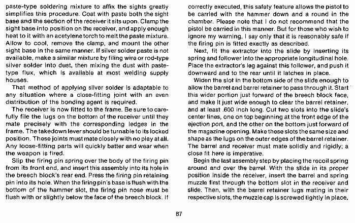
paste-type soldering mixture to affix the sights greatly simplifies this procedure. Coat with paste both the sight base and the section of the receiver it sits upon. Clamp the sight base into position on the receiver, and apply enough heat to it with an acetylene torch to melt the paste mixture. Allow to cool, remove the clamp, and mount the other sight base in the same manner. If silver solder paste is not available, make a similar mixture by filing wire or rod-type silver solder into dust, then mixing the dust with paste- type flux, which is available at most welding supply houses.
That method of applying silver solder is adaptable to any situation where a close-fitting joint with an even distribution of the bonding agent is required.
The receiver is now fitted to the frame. Be sure to care- fully file the lugs on the bottom of the receiver until they mate precisely with the corresponding ledges in the frame. The takedown levershould be turnable to its locked position. These joints must mateclosely with no play at all. Any loose-fitting parts will quickly batter and wear when the weapon is fired.
Slip the firing pin spring over the body of the firing pin from its front end, and insert this assembly into its hole in the breech block's rear end. Press the firing pin retaining pin into its hole. When the firing pin's base isflush with the bottom of the hammer slot, the firing pin nose must be flush with or slightly below the face of the breech block. If
correctly executed, this safety feature allows the pistol to be carried with the hammer down and a round in the chamber. Please note that I do not recommend that the pistol be carried in this manner. But for those who wish to ignore my warning, I say only that it is reasonably safe if the firing pin is fitted exactly as described.
Next, fit the extractor into the slide by inserting its spring and follower into the appropriate longitudinal hole. Place the extractor's leg against this follower, and push it downward and to the rear until it latches in place.
Widen the slot in the bottom side of the slide enough to allow the barrel and barrel retainerto passthrough it. Start this wider portion just forward of the breech block face, and make it just wide enough to clear the barrel retainer, and at least .600 inch long. Cut two slots into the slide's center lines, one on top beginning at the front edge of the ejection port, and the other on the bottom just forward of the magazine opening. Make theseslots the same size and shape as the lugs on the outer edges of the barrel retainer. The barrel and receiver must mate solidly and rigidly; a close fit here is imperative.
Begin the last assembly step by placing the recoil spring around and over the barrel. With the slide in its proper position inside the receiver, insert the barrel and spring muzzle first through the bottom slot in the receiver and slide. Then, with the barrel retainer lugs mating in their respective slots, the muzzle cap is screwed tightly in place,

Retract the sllde by gmsplng the checkered "ears" at the sllde's sequence cocks the gun and chambers r round. Take all poasi- rear end, pulling the sllde to the rear, then releasing It. Thla ble precaullons when you first test-lire the pistol.

locking the assembly firmly together. The slide-receiver unit is placed in position in the frame, and the takedown lever locked.
The pistol is now ready for its first test firing. Unless you are a fool, you will take certain safety pre-
cautions during this first test. For example, it is a good idea to tie or clamp the pistol to something solid while it is fired forthe first time, instead of hand-holding it. Bewarned that this may cause considerable damage to the gun if it is not secured correctly, so be careful. Once it is mounted, the trigger may be pulled the first time by means of a string or wire, so you can stand away from it in case something malfunctions.
Load a single round into the magazine first, and work the slide to chamber the round. Then using whatever pre- cautions you deem necessary, firethe round. If everything works properly when the trigger is pulled, the gun will fire and eject the empty case.
If it does not fire, the hammer spring is too weak or the firing pin spring too strong. Try a stronger hammer spring first. If the empty case is not ejected, the recoil spring is probably too stiff. Cut one coil from it and try again. If it still does not eject, cut off another coil. Repeat until proper ejection is achieved.
After the first successful firing, examine the fired case carefully for signs of splitting, cracking, and stretching. Does the firing pin indentation appear normal? Compare
the fired case to an unfired one. Did the dimensions change significantly? If you are satisfied that they did not, the gun can be test fired again for semi-automatic functioning.
Load two rounds into the magazine and test fire again. With the first round chambered, the pistol should fireonly once. It should then eject theempty caseand chamberthe second round. When the trigger is then released and pulled again, the second round should fire, repeating the cycle.
If the second round fires as the slide returns forward without the trigger being pulled a second time, the firing pin spring is too weak or the disconnector is too short. A disconnector that is too short allows the trigger bar to remain in engagement with the sear. Try installing astiffer firing pin spring first. If the second round still fires auto- matically, remove a little metal from the top edge of the trigger bar until it clears the sear when thedisconnector is depressed.
When the pistol fires two rounds satisfactorily, try firing a full magazine through it. Cut and perhaps bend the magazine lips and feed ramp slightly until cartridges feed smoothly and positively from the magazine to the chamber.
Adjust the sights by moving the front sight laterally in the direction where the point of impact is desired. Move the sight blade by tapping it gently with a hammer and


Chapter Nine
Hardening And Tempering
After all the pistol's parts are shaped to their finished dimensions, they must be hardened and tempered. The theory connected with tempering is quite simple, even though considerable confusion exists concerning it. In practice, though, the tempering/hardening procedures can be quitedifficult to properly accomplish. When steel is heat-treated, certain changes in the metal's molecular structure result which alter some of its physical proper- ties. Therefore, the most crucial aspect of this process is temperature. Steel heated insufficiently will not harden properly, while steel heated too much will actually burn.
To further clarify these concepts, I will briefly define the results obtained by heat treatments, which are: annealing, hardening, and tempering.
Annealing is the process of softening metal by heating it to a high temperature and allowing it to cool slowly. In most cases steel is annealed by slowly and completely cooling it from a cherry red heat. Ideally, this is done by
putting the steel in a cast iron box and covering it with some material such as sand, ashes, or fire clay. The box is heated in a furnace to the required temperature, after which the box and contents are removed, and cooled slowly enough to prevent any hardening. The material placed around the steel serves to exclude air, preventing oxidation. The sand also retains heat, allowing the metal to cool more slowly. Asomewhat crudeannealing method is the wood fire method described in Chapter Seven.
Hardening is the process of raising the temperature of the steel up to its decalescence point and then quenching it in a suitable cooling medium.
In practice, the steel to be hardened is heated slightly above its decalescence point. This insures that the temperature of the steel is not below its decalescence point, and also allows for a slight loss of heat while trans- ferring the steel from the heating source to thequenching bath.

A tempering furnace is the best way to harden steel. Such furnaces are designed specifically to heat steel evenly to high temperatures for tempering purposes. They are also shielded for protection of those working with them.
In the event no furnace is available, find another suitable source of heat. Large parts of even thickness can be heated with an acetylene torch. But the torch method is not suitable for thin and irregularly-shaped parts. The thin pieces are likely to burn when heated with aflame. To heat a small part safely, place it on a large piece of iron or steel, and heat the bottom piece to thedesired temperature. The small part to be hardened will soon reach the required temperature, and can then be removed and quenched.
Parts of irregular shape, having both thick and thin sections, are liable to overheat in the thin areas before the thicker portions reach the proper temperature. For this reason,, a lead bath is the best way to heat these parts. To prepare one, melt lead in a cast iron pot and cover its surface with powdered charcoal to prevent oxidation. The parts to be hardened are immersed in the lead bath and heated until they reach a red heat, then quenched.
Despite the irregularities of this system, it has many advantages, and may be used for hardening ortempering. Baths, whether salt, lead or oil, hold temperatures more uniformly than any other method, and are easier to main- tain at specific temperatures. Parts also heat more rapidly
in such baths. Just be certain that the bath's temperature is uniform before using it. Cold steel can not be immersed in a heated bath, due to the danger of cracking it. Thesteel must be preheated to around 300 degrees F. before placing it in the bath. Preheating is not necessary if the bath is at a comparatively low temperature when the steel is placed in it. The bath is then heated to the desired temperature. This last procedure is most commonly done with oil or salt baths, which remain liquid at low temperatures.
When parts are taken from an oil bath, immerse them in a tank of caustic soda, then water, to remove any oil adhering to the part.
After hardening, the parts are ready for tempering. That is because the hardening process has not only made the parts extremely hard, but also brittle.
Tempering is the process of reheating previously hardened steel, then quenching it, resulting in tougher, less brittle steel.
The worst part of it is the tempering process softens the metal as well as toughening it. Toughness and also softness obtained in tempering depend on the degree of heat to which the metal is raised. The higherthe heat used, the less brittle it will be and also less hard.
Tempering hardened steel is best done in a specially prepared tempering bath; a metallurgist's high tempera- ture thermometer is used in conjunction with the bath.
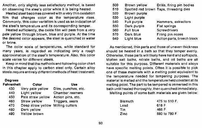
Another, only slightly less satisfactory method, is based on observing the steel's color while it is being heated.
Heated steel becomes covered with a very thin oxidation film that changes color as the temperature rises. Commonly, this color variation is used as an indication of the steel's temperature and its corresponding temper.
Heated sufficiently, the oxide film will pass from a very pale yellow through brown, blue and purple. At the time the desired color appears, the steel is quenched in water or brine.
The color scale of temperatures, while standard for many years, is regarded as indicating only a rough approximation of the steel's temperature. Also, this color scale varies for different steels.
Keep in mind that the methods and following color chart in this chapter apply to carbon steel only. Certain alloy steels require entirely different methods of heat treatment.
Degrees Fahrenheit Color Use
430 Very pale yellow Dies, punches, etc, 440 Light yellow Chamber reamers 450 Pale straw yellow Action pins, etc. 460 Straw yellow Triggers, sears 470 Deep straw yellow Milling cutters 480 Dark yellow 490 Yellow brown
Brown yellow Drills, firing pin bodies Spotted red brown Taps, threading dies Brown purple Light purple Full purple Hammers, extractors Dark purple Flat springs Full blue Screwdrivers Dark blue Firing pin noses Light blue Action parts, breech block
As mentioned, thin parts and those of uneven thickness should be heated in a bath so that they temper evenly. Otherwise, these parts will likely have hard and soft spots. Molten salt baths, nitrate baths, and oil baths are all suitable for this purpose. Different materials and alloys have specific melting points. Often it is possible to pick one of these materials with a melting point equivalent to the temperature needed for tempering purposes. The material is melted and the temperature held constant at its melting point. The part to be tempered is immersed in this bath until heated thoroughly, then quenched immediately.
Melting points of some bath materials are given below:
Bismuth 475 to 510 F. Lead 618 F Tin 466 F Zinc 680 to 780 F
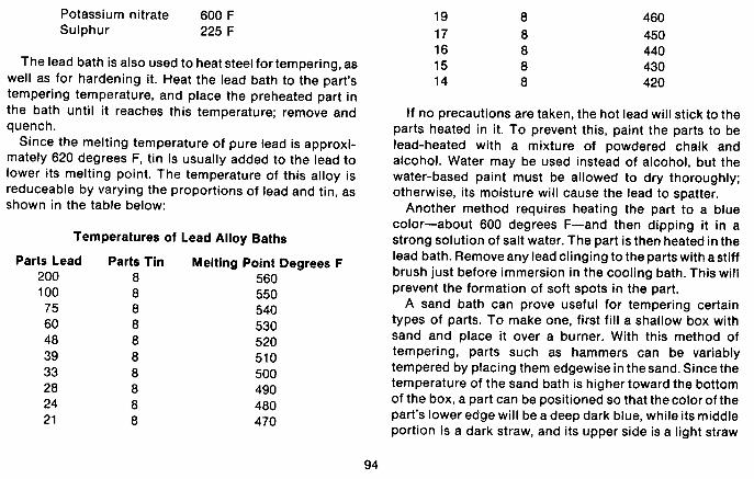
Potassium nitrate 600 F Sulphur 225 F
The lead bath is also used to heat steel for tempering, as well as for hardening it. Heat the lead bath to the part's tempering temperature, and place the preheated part in the bath until it reaches this temperature; remove and quench.
Since the melting temperature of pure lead is approxi- mately 620 degrees F, tin is usually added to the lead to lower its melting point. The temperature of this alloy is reduceable by varying the proportions of lead and tin, as shown in the table below:
Temperatures of Lead Alloy Baths
Parts Lead 200 100 75 60 48 39 33 28 24 2 1
Parts Tin 8 8 8 8 8 8 8 8 8 8
Melting Point Degrees F 560 550 540 530 520 510 500 490 480 470
If no precautions are taken, the hot lead will stick to the parts heated in it. To prevent this, paint the parts to be lead-heated with a mixture of powdered chalk and alcohol. Water may be used instead of alcohol, but the water-based paint must be allowed to dry thoroughly; otherwise, its moisture will cause the lead to spatter.
Another method requires heating the part to a blue color-about 600 degrees F-and then dipping it in a strong solution of salt water. The part is then heated in the lead bath. Remove any lead clinging to the parts with a stiff brush just before immersion in the cooling bath. This will prevent the formation of soft spots in the part.
A sand bath can prove useful for tempering certain types of parts. To make one, first fill a shallow box with sand and place it over a burner. With this method of tempering, parts such as hammers can be variably tempered by placing them edgewise in thesand. Sincethe temperature of the sand bath is higher toward the bottom of the box, a part can be positioned so that the color of the part's lower edge will be a deep dark blue, while its middle portion is a dark straw, and its upper side is a light straw
color. Thus the part's hardness gradually increases from its bottom to its top.
Molten salt baths are also useful for tempering or drawing operations. Nitrate baths are particularly adapted to the usual tempering/drawing temperature range of 300 to 1100 degrees F. Tempering in an oil bath is generally limited to a temperature of 500 to 600 degrees.
Uneven heating is the principal cause of most hardening defects. Cracks running from the corners or edges of the part are indicators of such uneven heating. Vertical cracks and dark-colored fissures indicate that the steel has been overheated and burned. Pieces having hard and soft places have either been unevenly heated, unevenly cooled, or soaked- a term which means overheated. Parts not moved around in the hardening liquid will show hard and soft spots, and may have a tendency to crack. Similarly, those which are hardened simply by dropping them to the bottom of the tank will likely have soft places, due to contact with the bottom or sides of the tank. Also, thoroughly quench parts before dropping them to cool completely.
Too much heat or soaking too long usually decarbon- izes the surface of the metal, in which case it will not harden properly until the surface is removed.
Overheated steel that is not actually burned is partially restoreable. Begin by heating it to the right temperature, and allow it to cool slowly in hot sand or ashes. After
cooling, the steel is again hardened. If the over-heating originally resulted during a forging operation, thechances of the part cracking during the next hardening will be reduced by using this process.
Except where noted, the small parts described here must be heat treated. If left in a softened or annealed state, they will be brittle and break. If you take my suggestion, and use drill rod and annealed automobile spring to make these parts, the heat treatment will present few problems. Obtaining and recognizing the proper hardening and tempering temperatures present the biggest problem in this situation. And the use of the hardening and temper- ing baths will simplify this step appreciably.
In the event that tempering baths are unavailable, and the acetylene torch or forge is used to heat the parts, pay close attention to the following procedure, which I described briefly at the beginning of this chapter.
Begin by placing small irregularly-shaped parts on top of a large iron or steel plate. Heat the plate to a cherry red heat. When the parts also reach a cherry red heat, quench them in water.
The next step is to "draw" the temper. The part is polished bright, and again placed on the heated plate until the proper tempering color appears. Remove again and quench in water.
By referring to the chart shown earlier in this chapter, it may be seen that the hammer should be drawn at a dark
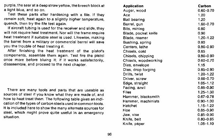
purple, the sear at a deep straw yellow, the breech block at a light blue, and so on.
Test these parts after hardening with a file. If they remain soft, heat again to a slightly higher temperature, quench, then try the file test again.
If aircraft tubing is used for the receiver and slide, they will not require heat treatment. Nor will the frame require heat treatment if suitable steel is used. Likewise, making the barrel from a military or commercial barrel will save you the trouble of heat treating it.
After finishing the heat treatment of the pistol's components, assemble them again. Test fire the pistol once more before bluing it; if it works satisfactorily, disassemble, and proceed to the next chapter.
There are many tools and parts that are useable as sources of steel if you know what they are made of, and how to heat treat them. The following table gives an indi- cation of the types of carbon steels used in common tools. It is included here to show the many alternate sources for steel, which might prove quite useful in an emergency situation.
Application Auger, wood Ace Ball bearing Barrel, gun Bits, mining Blade, pocket knife Blade, reamer Bushing, spring Centers, lathe Chisels, cold Chisels, chipping Chisels, woodworking Dies, envelope Dies, drop forging Drills, twist Driver. screw Edge, straight Facing, anvil Files Hammer, blacksmith Hammer, machinists Hatchet Hoe Jaw, vise Knife, belt Knife, paper
Carbon 0.60-0.70 1.20 1.20 1.60-0.70 0.80 0.90 1.20-1.22 0.80 0.80-0.90 0.85 0.80-0.90 0.60-0.70 1.15 0.85-0.90 1.20-1.22 0.60-0.70 1.05-1.12 0.85-0.90 1.25-1.30 0.67-0.78 0.90-1 .OO 1.1 5-1.22 0.85-0.90 0.85-0.90 0.80-0.85 1.05-1.10

Application Knife, woodworking Knife, putty Magnet Machinery, crucible Mower, lawn Plow, crucible Punch, blacksmith Rake Saws, circular Saws, for steel Saws, for crosscut Saws, band Skate Spring, common Locking Truck, tractor Taps Tools, blacksmiths Tools, moulders
Carbon 1.15-1.20 0.90-1 .OO 1.23-1.25 0.55-0.65 1 .oo 0.85-0.90 0.80-0.85 1.1 5-1.25 0.80 -0.90 1.60 0.85-1 .OO 0.68-0.75 1.15

Chapter Ten
Finishing and Bluing
In the preceding volume of this series, I described the methods and materials used in the hot "nitrate" processof bluing (or "blacking") parts of a firearm. In this volume, I will present sufficient information to enable you to finish weapons with both the comparatively slow nitrate process, as well as a faster rust-type bluing (or "brown- ing") procedure.
Let me mention here that you must take every precaution possible to protect your eyes and skin from the more caustic bluing formulas that follow, particularly the "hot" solutions. When mixing any bluing formula, add water to it slowly by means of a long handled dipper so that any chemicals that spatter out then will not reach you. An even safer method is to place a funnel in the end of a five foot section of pipe and pour the water through it. Some chemicals listed here are extremely dangerous when handled carelessly.
Note that considerably less equipment is necessary for
the quick rust-type of finish than with the nitrate blue. In fact, for the faster method, one tank approximately five inches high, five inches wide, and long enough to accept the longest part to be blued is adequate. For the pistols described in this book, a tank length of 14 to 16 inches will suffice. It can be heated on a kitchen stove if noother heat source is available.
But if you anticipate doing very much bluing, it is advantageous to make three tanks together with a rack to hold them, with individual burners for each. Construct the tanks from any material that can withstand the temperature needed to boil water. Trays from discarded room planters, poultry feeders, or even a section of rain gutter with endcaps brazed in place are fine. Another source for suitable tanks is old rocker arm or valve covers at the automotive salvage yard.
Mark these tanks numbers one, two, and three. Tank number one is the degreasing tank. It will contain astrong

Here Is the blulng lank set-up that I use In my shop. From lelt to rlghl are the cold water rinse tank, blulng tank (wHh Ihermometer), degreaslng tank,
and hob water rlnse lank. Nol shown is the 011 tsnk along the wall 'behind these
lanks.
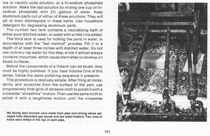
lye or caustic soda solution, or a tri-sodium phosphate solution. Make the last solution by mixing one cup of tri- sodium phosphate with 2% gallons of water. Keep aluminum parts out of either of these solutions. They will pit or even disintegrate in these baths. Use househotd detergent fox degreasing aluminum parts.
The number two tank contains a neutralizing bath of either pure distilled water, or water with a little lime added.
The third tank is used for boiling the parts in water, in accordance with the "fast method" process. Fill it to a depth of at least three inches with distilled water. Do not use ordinary tap water forthis step, since it almost always contains impurities, which cause blemishes to develop on blued surfaces.
Before the components of a firearm can be blued, they must be highly pollshed. If you have Volume One of this series, follow the same polishing sequence it presents.
This procedure is refatively simple. After filing all nicks, dents, and scratches from the surface of the part, use progressively finer grits of abrasive cloth to polish it with a crosswise "shoeshine" motion. Then use the samecloth to polish it with a lengthwise motion until the crosswise
My bluing tank burnera were made from pipe and mlnlng valves sal- uaged from discarded gas stoves and hot waler heaters. Two rows of holes were drilled In the top of each plpe.
marks are polished out. Repeat with the next finer grit, eventually progressing to crocus cloth, until the steel has a shiny, chrome-like appearance. Finally, check the part under a strong light for blemishes or dull spots. These must be removed if a professional-looking finish is expected.
Immediately prior to bluing, clean all parts completely, making certain they are free of oil or grease. Wear clean cotton gloves throughout the cleaning operation, since human skin secretes oil and sometimes acids. An imperceptible layer of these secretions, which may prevent the bluing solution from working properly, will result if you handle parts without gloves.
Prepare to blue the barrel by making hardwood plugs that fit into each end of it. These plugs should be at least 3/4 inch in diameter, and long enough toserveas handles. The premanufactured dowel rod available at most lumber yards is ideal for this purpose. Using a wood lathe, turn a shoulder on one rod a few thousandths of an inch larger than the barrel's bore diameter. Make the plug for the muzzle end of the barrel five or six thousandths of an inch greater than the barrel's groove diameter. Grease it lightly and drive it into the bore, allowing approximately 1/2 inch to remain between the muzzle and the plug shoulder, insuring that the end of the muzzle will be acceptably blued also.
Drive a similarly-fitted and greased plug into the
chamber end of the barrel. Properly done, the two plugs will prevent any trace of the bluing solution from reaching the inside of the barrel.
Most of the other parts are handled during bluing by wooden plugs fitted into holes present in the respective parts. Similarly, screws and bolts may be handled during bluing by drilling appropriate holes in wood strips, then screwing these screws and bolts into the holes. Small parts that have no holes or openings present another problem. Handle these by the free end of a stiff wire wrapped around an area of the part that does not require bluing.
Before you start the actual bluing, bend three U-shaped brackets from heavy wire, such as coat hanger or welding rod. Position one of these in each tank, to prevent larger parts from contacting the bottom of the tank. I also recommend making a pair of hooks from about 3/16 inch diameter steel rod. Use the hooks to both place the parts in the tanks and remove them.
Presently, it is possible to purchase commercial bluing solutions which will satisfactorily color and protect the metal if used according to directions. Herter's Belgian Blue, Stoeger's Yankee Blue, and Brownell's Dicropan IM are three of the more popular home-bluing solutions on the market. Prices and container sizes vary, but all produce nearly identical results by following essentially the same application technique.

Because this book is intended for a time when such commercial preparations may not be available, the following formulas are included so that you can mix your own bluing solutions.
Fast Process
750 Gr. Corrosive Sublimate 1000 Gr. Potassium Chlorate 1200 Gr. Potassium Nitrate 300 Gr. Ferric Chloride 150 Gr. Cupric Chloride 300 Gr. Sodium Nitrate
Place the above six chemicals in a glass receptacle. Chances are you may have to get them already mixed at a drug store since potassium chlorate is an explosive under certain conditions, and will probably be difficult to obtain separately. Heat 1700 CC of distilled water to 130 degrees F. and pour it into the glass receptacle. Agitate the mixture until all the chemicals are completely dissolved and allow to cool.
After about ten hours, add 175 CC sweet spirits of niter. Shake well and pour the solution into colored glass bottles; allow to stand twenty-four hours before using. Bottles should be labeled POISON.
This solution is one of the best for the fast-method
bluing. It only takes about an hourto complete, and results in a fine, extremely durable, blue finish if directions are carefully followed.
After all the parts to be blued are well polished, wash them thoroughly, preferably with a non-flammable solvent. Place them in the first tank which containsat least three inches of water and a proper amount of the tri- sodium phosphate (one cup to 2% gallonsof water). Bring this solution to a boil, then immerse the parts in it, and allow them to boil for fifteen minutes. Any traces of oil or grease will be removed by thisstep. They are next rinsed in tap water, and placed in tank number two containing lime water (one ounce to two gallons). Boil again.
Following the completion of the first two steps, pour three or four inches of distilled water into tank number three. Again, if distilled water is not used in the last tank, the final blue finish will likely be streaked and discolored.
Procure a heavy glass pint jar with a large mouth, and wrap a heavy wire around its top. Use this wire to fasten the jar in one corner of the third tank allowing it to rest on the tank's bottom. Pour enough of the bluing solution into the jar to fill it half-way. Make certain that no water gets into the solution.
But before you boil the water and jar of bluing solution in tank number three, three things are needed: a swab, 00 to 000 steel wool or afine carding brush, and a rack to hold the barrel by its two end plugs. Make the swab by tying a
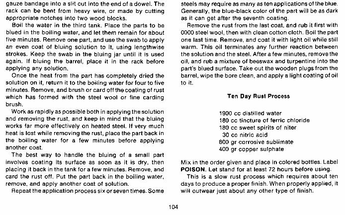
gauze bandage into a slit cut into the end of a dowel. The rack can be bent from heavy wire, or made by cutting appropriate notches into two wood blocks.
Boil the water in the third tank. Place the parts to be blued in the boiling water, and let them remain for about five minutes. Remove one part, and use the swab to apply an even coat of bluing solution to it, using lengthwise strokes. Keep the swab in the bluing jar until it is used again. If bluing the barrel, place it in the rack before applying any solution.
Once the heat from the part has completely dried the solution on it, return it to the boiling water for four to five minutes. Remove, and brush or card off thecoating of rust which has formed with the steel wool or fine carding brush.
Work as rapidly as possible both in applying thesolution and removing the rust, and keep in mind that the bluing works far more effectively on heated steel. If very much heat is lost while removing the rust, place the part back in the boiling water for a few minutes before applying another coat.
The best way to handle the bluing of a small part involves coating its surface as soon as it is dry, then placing it back in the tank for a few minutes. Remove, and card the rust off. Put the part back in the boiling water, remove, and apply another coat of solution.
Repeat the application process six or seven times. Some
steels may require as many as ten applicationsof the blue. Generally, the blue-black color of the part will be as dark as it can get after the seventh coating.
Remove the rust from the last coat, and rub it first with 0000 steel wool, then with clean cotton cloth. Boil the part one last time. Remove, and coat it with light oil while still warm. This oil terminates any further reaction between the solution and the steel. After a few minutes, remove the oil, and rub a mixture of beeswax and turpentine into the part's blued surface. Take out the wooden plugs from the barrel, wipe the bore clean, and apply a light coating of oil to it.
Ten Day Rust Process
1900 cc distilled water 180 cc tincture of ferric chloride 180 cc sweet spirits of niter 30 cc nitric acid
800 gr corrosive sublimate 400 gr copper sulphate
Mix in the order given and place in colored bottles. Label POISON. Let stand for at least 72 hours before using.
This is a slow rust process which requires about ten days to produce a proper finish. When properly applied, it will outwear just about any other type of finish.
Prepare the handgun's parts for bluing by polishing and most respects to many of its commercial counterparts. degreasing, as previously described. Repeat the Good luck and good shooting! processes for tanks one and two, as outlined under "Fast Process." Boil distilled water in tank number three, along with the pint jar half-full of bluing solution. Placethe parts to be blued in the boiling water for five minutes. Remove, and use a clean swab to coat the part with solution. Allow it to stand between eight and ten hours before carding off the rust with steel wool or a wire brush. Then boil it in tank three for five minutes, to neutralize any remaining chemicals from the previous coat. Remove the part, and allow it to cool a bit. Swab on another coat of thesolution.
Repeat this operation on each part twice a day for nine or ten days. Provided that you followed the directions completely and carefully, used distilled water, polished the parts meticulously, and paid strict attention to the degreasing process, you will have one of the finest blue jobs that it is possible to produce.
If there is not sufficient humidity for a coat of rust to form in the given time, make a box to completely enclose the work and place a pan of warm water in the bottom of it. The box will usually increase the humidity enough to allow the coating of rust to form adequately.
The parts are now ready for final assembly. If you've done your "homework," you will now have a
reliable, accurate semi-automatic pistol comparable in

Chapter Eleven
Single-Shot Design
Most of the component parts for the single-shot falling block pistol presented in this chapter are similar to the corresponding parts used in the previous semi-automatic design. Therefore, I will not go into great detail on constructing them. This being the case, do pay close attention to the drawings and dimensions as presented in the following pages.
This pistol's receiver is made from a solid steel block 3% inches long, 1 '/2 inches wide, and one inch thick. If it is to be chambered for a high-intensity cartridge, be sure to make the receiver from a block of quality steel. If avail- able, S.A.E. 4340 steel is ideal for this purpose. Once machined to size and shape, the 4340 steel is heated to 1475 to 1525 degrees F., then quenched in oil, and the temper drawn at 1100 degrees F. The receiver's hardness should then equal C35 on the Rockwell scale, or a tensile strength of 160,000 pounds per square inch, and a yield strength of 138,000 pounds per square inch. So the
strength of this 4340 receiver will safely handle just about any small arms cartridge commercially available today.
If only low-pressure cartridges are contemplated, then the receiver may be machined from scrap steel such as plow beam, etc. However, I strongly urge that you use a quality steel of known analysis so that it can be properly heat treated.
Cut the block of steel to the receiver dimensions previ- ously given, by sawing, filing and grinding, or milling.The next step is to lay out a center-line along the block's top, bottom and both ends. This line fixes the location of the barrel, breech block, hammer, and trigger, so make certain that it is centered exactly all the way around.
1% inches back from its front edge, punch a markon the center line at the block's top and bottom sides. These locate the center of the breech block opening, which is drilled and reamed to a finished diameter of .750 inch. One-half inch down from the block's top edge, make two
1 .300" k 7 1 6 - 4 7/8 x 27 Thread
Thread
SINGLE SHOT RECEIVER
SINGLE SHOT RECEIVER
punch marks on the center line, one on the front face and one on the rear. The barrel will thread into a 1/2 inch hole centered on these marks. Bore this hole completely through lengthwise. Drill and ream the length of this hole forward of the breech block opening toafinished diameter of 11/16 inch. Thread thefirst .800 inch of this hole back from the front face with a 3/4 inch x 16 thread. The bottom side of the breech block opening is also threaded, to a depth of 3/8 inch using a 7/8 inch x 27 thread. The portion of the breech block holeto bethreaded must first be reamed out to a diameter of 27/32 inch , which is the proper tap drill diameter for a 7/8 inch x 27 thread.
I suggest holding the receiver in a lathe's four jaw chuck while it is being drilled, bored, or reamed. The threading should also be done in the lathe even if taps are used to cut the threads. "True" alignment is much more easily achieved using this method.
Cut a 1/4 inch wide slot on the center line and at the rear of the breech block opening, for the hammer and sear. If the rear end of the breech block is cut to the contour shown in the diagram before this step, the slot will be slightly easier to cut since ther will be less metal to remove. Cut away the upper portion of the 1/2 inch length- wise hole (to the rear of the breech block opening) until it is the same width as its diameter (.5 inch), leaving the bottom half rounded. Cut a 1/4 inch wide slot at the lower front for the upper end of the trigger, and a 1/8 inch slot for
an extractor at the left front side of the breech block opening. Some of the steel removed from these slots can be drilled out, but their inside corners will have to be removed with files and narrow chisels. The extractor slot particularly is difficult to cut to the finished shape, but with a sharp chisel and a lot of patience, it can be done.
Drill the holes for the trigger and sear pins with a No. 31 drill through both sides of the receiver. One side is drilled out to 1/8 inch. The smaller No. 31 holes will hold the 1/8 inch pins securely in place. The hole for the hammer screw is first bored with a No. 3 drill, followed by a 1/4 inch drill through one side, which is also counterbored for the screw head. Tap its oppositeside for a 1/4 inch x 28 thread. The top of the receiver forward from the breech block opening can now be rounded or filed to an octagon contour. The upper and rear end edges should be rolled or rounded off slightly, but the bottom side and front face must be kept sharp and square.
Thread a five inch long section of 7/8 inch seamless tubing with an inside diameter of 3/4 inch on one end to screw tightly into the bottom of the breech block opening. The pistol's wooden grip will be fitted around this tube.
If tubing is not available, a section of 12-gauge shotgun barrel cut from the heavier part near the breech end can be reamed almost to size and turned to the outside diameter. Then screw it in place and ream it to finished size, together with the breech block opening. This will insure correct

alignment, assuring that the breech block will work as 7/8 x 27 Thread designed.
Lay out and cut the slots in the front and rear sides of this tubing as shown in the diagram, using the cutting methods described for the slide and receiver of the semi- automatic handgun. The small slot near the top is for a bar connecting the trigger and sear, and while there must be some up-and-down clearance, the sides should fit this connecting bar closely.
Construct the breech block from round stock polished to slip fit closely inside the breech block opening. Use the same 4340 steel used for the receiver i f possible. It may be heat treated to the same hardness as the receiver, or left slightly harder by drawing at 1000 degrees F. This will afford a reading of C38 Rockwell, a tensile strength of 178,000 pounds per square inch, and a yield strength of 156,000 pounds per square inch for the breech block. Here again, an automobile axle or similar steel parts can be used for the breech block, but when steel of unknown analysis and composition is used, the results of the heat treatment are uncertain.
Trim the breech block to an overall length of two inches, and mark a center line completely around its top, bottom, front and rear. A 3/16 inch wideslot is cut from front to rear centered on the bottom centerline, extending upward 1 '/s 4 318" inches. To start this slot, drill a hole slightly smaller than its finished width, through the block, then saw through GRIP FRAME & BREECH BLOCK GUIDE
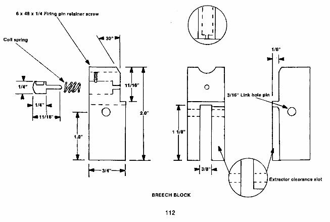

each side of the slot with a hacksaw. Square the bottom and sides of the slot by filing and chiseling.
Drill a hole as indicated from left to right for a 3/16 inch link pin. Use a slightly smaller drill for this hole first, preferably a No. 16. Then drill onesideof the breech block with a 3/16 inch bit. A hardened pin from 3/16 inch drill rod should then fit tightly through these holes, serving as the link pin.
Finish the upper front face of the block to aflat surface where it fits against the breech end of the barrel. Cut it back until the flat area measures at least 5/8 inch (.625 inch) across and 11/16 inch (.6875 inch) high when meas- ured down from the top. You must bevel this flat area's top front edge to the rear slightly, which will allow it to assist in camming the extractor shut as the breech block rises. Center and cut a rounded trough lengthwise to the top of the breech block, not more than 3/16 inch deep.
Wait until the barrel is in place and the lever and link connected before drilling the firing pin hole in the breech block. To mark its location, first turn a sharp point on a rod which is a close slip fit in the bore, and slightly longer than the barrel. With the breech block closed and the lever latched, insert the rod into the barrel, pointed end first. Once in place, tap the rod's butt with a hammer. This will accurately mark the firing pin location in the exact center of the bore, assuring that the firing pin will strike the primer in its center, and not high, low, or off to onesideas
many falling block designs do. If a rimfire cartridge is intended, move the firing pin
location upward the distance necessary to contact the cartridge rim.
Bore the firing pin hole with a 1/16 inch drill, followed by a 1/4 inch drill to accommodate the firing pin body and retraction spring. Also drill a 1/8 inch hole to serve as a gas vent from the top center into the firing pin hole. The vent allows gas to escape in the event of a blown primer. A firing pin retainer is also installed to hold the firing pin in place. The firing pin hole should be plugged while this hole is made with a No. 31 drill, to keep the drill from wandering. Thread the upper part of this hole with a 6 x 48 tap, and make the retainer pin to the dimensions shown.
The firing pin is made from 1/4 inch drill rod. Turn the rod's front portion until it slip fits in the firing pin hole. Actual protrusion of the pin should be .060 inch. Use a small coil spring to retract the firing pin, which occurs when the hammer is pulled back to the half-cock or safety notch.
If an extremely high intensity cartridge is contemplated, the front installed firing pin and the flat-backed breech block designs shown as alternatives in the drawings may be used for added strength and durability. This design requires a square flat face at the rear of the barrel breech block opening in the receiver.
I have built this pistol in .22 WRM and .357 magnum

calibers, and used the first breech block firing pin system in both, with entirely satisfactory results. The alternate is shown simply to satisfy those who feel they must have it that way.
The barrel blank is procured or constructed in the same manner described for the other handgun. It can be about any length you want. The only requirement is that the barrel must have a 7/8 inch (.875 inch) shoulder to butt up against the forward end of the receiver. The barrel on the gun shown has an overall length of seven inches, a muzzle diameter of 5/8 inch (.625 inches), and a straight taper expanding to 7/8 inch (.875 inch) 112 inch forward of the thread shoulder. This leaves a cylindrical section ,500 inch long and .875 inch in diameter. The barrel shank is 1.6 inches long, with the first .800 inch turned smooth to a diameter of 11/16 inch (.6875 inch), and the adjacent portion turned to3/4 inch (.750inch), then threaded with a 3/4 inch x 16 thread.
Make sure that when the barrel is screwed in place tightly, the breech end almost contacts the face of the breech block with no more than .005 inch clearance be- tween them.
While the barrel is in place, locate and mark its top center. A front sight made as shown is silver-soldered in place just behind the muzzle end of the barrel on the center line.
Another center line is located and marked on the bottom
side of the barrel, and a nut or boss affixed to it for the forend retainer screw to thread into. Make this nut from 1/4 inch round stock, 5/16 inch long. Radius its top to fit the barrel contour, and drill and tap the nut for the size screw you have available. An 8 x 40 x 1/2 inch screw will do nicely forthis, in which case the proper drill would be a No. 28. If it is necessary to use an 8 x 32 or 8 x 36 thread. both of which are available at most hardware stores (the 8 x 40 is not), then drill the hole with a No. 29 drill.
Mark the extractor location while the barrel is in place in the receiver. Remove the barrel, and cut the extractor slot with files and a narrow chisel. With this accomplished, the chamber is cut almost to depth and the barrel re-installed.
Cut the extractor from 1/8 inch sheet steel, and bend its upper end to a right angle. The extractor's upright portion should fit closely in itsslot in the receiverwithout side play or wobble. A hole is drilled in the receiver for an extractor pivot pin with a corresponding hole through theextractor. Drill these with a No. 31 drill and tap the first part of the receiver hole with a 6 x 48 tap. Turn the threads off the lower end of a 6 x 48 screw and remove the screwhead. Cut a narrow slot across this screw's top to enable use of a screwdriver, and use it for the pivot pin.
The upper extractor leg that fits in the barrel slot is fitted by filing, spotting, and filing again until it fits. Use a round file to remove all the portion possibleextending across the chamber opening. To finish cutting the chamber to its
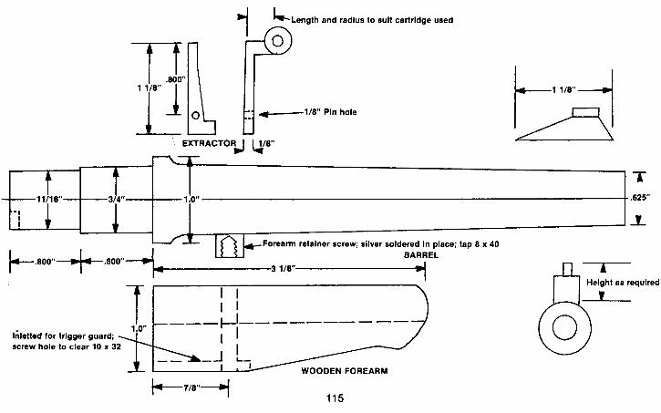
Length and radius to suit cartridge used 1s U
EXTRACTORJ u / 8 " u
- 1
I 1 Forearm retainer screw; silver soldered in place; tap 8 x 40
BARREL ~ . 8 0 0 ~ . 8 0 0 " ~ 'n'31/w 7
Height as required
I I I I
iilietted for trigger guard; screw hole to clear 10 x 3
WOODEN FOREARM
proper depth, screw the barrel in place in the receiver with the extractor in its closed position. This will properly align the contact between barrel and extractor. Now the actual cutting is done by hand.
The lever is cut from 1/2 inch flat stock. It will require quite a bit of sawing and filing to cut it to final shape; just persevere and be patient.
Note that the lower end of the lever is cut to a width of 1/4 inch, with a 3/16 inch hole drilled for a pivot pin. Its upper end is also drilled, to receive a lower link pin. Cut a 3/16 inch wide slot for the link pin to fit in. A longitudinal recess 3/8 inch wide is cut in the horizontal part of the lever for the lower side of the trigger guard to fit into. This recess is made with either the edge of a flat file or with a small square file, except forthe portion at the extreme rear end. Cut this area out with a chisel ground slightly narrower than the 3/8 inch slot width.
The latch, which is pinned into the outer end of the lever, is made from 3/8 inch flat stock. Trim its upper portion, which latches into the front of the trigger guard, to a width of 1/4 inch. Drill a hole for the pivot pin into the latch, and checker or groove the latch's upper surface. Also, drill a recess at the lower front of the latch for a suitable coil spring to fit into. This spring exerts upward pressure on the lever latch.
3/16 inch flat stock is used to make the link. Select steel that you know how to harden properly for the link. The leaf
spring steel mentioned previously will work well for it.The link should be just thick enough to work freely in both the slot in the upper end of the lever and the slot in the breech block.
The 3/16 inch link pin holes must be as close to the specified distance of 1.250 inches as is possible, so that the link pin will cam "over center," and hold the breech block securely in its closed position. The resulting downward pressure on the breech block will actually force the lever tighter against the lower trigger guard, insuring that the firing pin will strike the primer in the same position each time the gun is fired.
Make the trigger guard from two pieces of 1/8 inch flat stock. A flat plate is cut to the shape shown, then slotted for the trigger, with screw holes drilled and counterbored front and rear. Drill these holes with a No. 18 drill to provide clearance for 8 x 30 screws. The forend retainer screw goes into the front hole, and a corresponding hole for the rear screw is drilled and tapped into the bottom of the receiver.
A guard bow is bent to shape as shown from a 3/8 inch wide strip of the same stock and welded to the plate. If the welds are built up slightly and the rounded filletsfiled with a round file and polished smooth, a better appearance will be achieved. Note the slot in the right rear side. This is to provide clearance for the trigger bar. The rectangular opening at the lower front engages the lever latch and

SEAR p-,2 118"-4
TRIGGER BAR 4 l/W
TRIGGER


should be left slightly undersize until final assembly, at which time both this opening and the latch are fitted to hold the lever firmly against the lower trigger guard.
The hammer, trigger, and sear are fabricated to the sizes and shapes shown in the drawings, using the same methods described for the other gun. If a wide target-type hammer spur is desired, leave the spur thicker and heat and forge it wider. Bend the trigger bar to shape as shown and drill it for the pins that fasten it to the trigger and sear. Use 1/16 inch pins to hold the bar in place.
Make a hanger from 1/2 inch flat stock to slip into the slot in the lower part of the frame upright. This hanger serves as a hammer spring guide and pivot point for the lower end of the lever, and the stock retaining bolt also threads into it. Cut it to the shape shown and cut the slot for the lever. Drill the hole for the stock bolt with a No. 3 drill and tap for 1/4 inch x 28. Use a machine screw of this thread to hold the grip or stock in place. Drill a 3/16 inch hole as shown for a lever pivot pin and another from the upper side at the extreme rear for the hammer strut to fit through.
The combination hammer strut and spring guide is made as shown from 1/8 inch flat stock. A suitable coil spring for the hammer spring is now needed. It must be big enough inside to clear the hammer strut and at least 1% inches long. Start with a heavier spring than is necessary, and cut and try it until suitable.
Construct a grip retainer plate as shown from 1/4 inch flat stock. Drill the hole and counterbore it for the screw head.
Another hanger is made, which is silver-soldered to the upper rear side of the tubular frame upright. The sear mounts in this hanger since the frame doesn't extend downward far enough to permit pinning it to the frame. Slot a block and drill for the sear pivot pin, radius thesolid end to the same contour as the frame upright, and silver- solder it in the location shown.
There are a number of commercial rear sights available that could be used if you so desire, or a sight similar to the one shown for the semi-automatic can be made and used. In the event that afully adjustable rearsight is required but is not obtainable, drawings and dimensions are included for building such a sight.
The grip is a one piece design. Begin it by boring a hole lengthwise through a hardwood grip blank to allow it to slip over the frame upright. Clearance must be cut to the front and rear of the hole for the hammer spring, trigger guard, and other projections. When it will slip fully in place, inlet the retainer plate into the bottom and bolt it in place. The grip's exterior is then cut to theshape shown, or whatever shape is preferred, and sanded, finished, and checkered as described for the other gun.
A forearm is also made from the hardwood as shown. With the forearm's rear end flush against the forward end
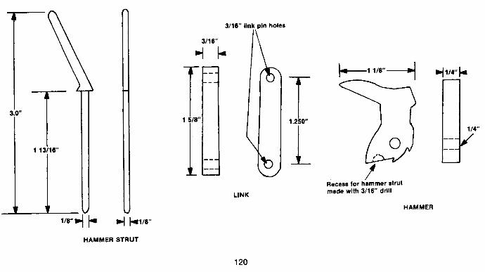
HAMMER
3/16" )Ink pin holes
3/16"
4 kl/e.. STRUT
LINK
Recess for hammer strut made wlth 3/16" drill
HAMMER
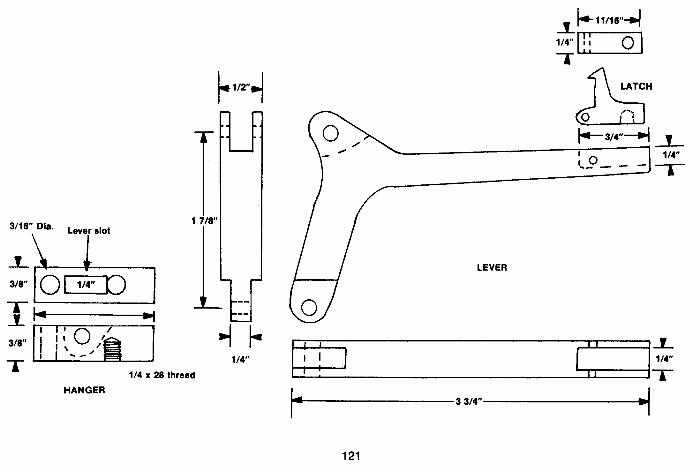
3/16'1 Laver riot
1/4
thread
LEVER
HANGER 3 3/4-4

of the frame, inlet it until the barrel restsat half-depth. The forward end of the trigger guard is also inletted into the forearm's bottom side at the rear. Finish by shaping, sanding, sealing and checkering.
Final assembly of the single-shot pistol is begun by screwing the barrel and the frame upright into the frame.
Pin the upper end of the link to the breech block and slip it into the frame. The extractor is next placed in position and fastened in place. Pin the lower end of the lever to the hanger and install it in the frame upright. The lower end of the link is then fastened to the lever.
Mount the trigger and spring in the frame and install the trigger guard, after which the sear is pinned in place and the trigger bar installed, connecting the trigger and sear. Slip the spring over the lower end of the hammer strut and insert the end of the strut into the guide hole, and fasten the hammer in place. Install the grip by slipping it overthe frame upright, mounting the retainer in the bottom of the grip, and bolting it in place. Mount the forearm by removing the front trigger guard screw, slipping the forearm in place, and replacing the screw.
Following assembly, the gun is ready to be test fired. As described for the other gun, precautions must be taken to prevent injury during the actual test firing.
Examine the first fired case carefully for signs of splitting, cracking, and stretching. Check the firing pin indention, and compare the fired case to an unfired one.
Make sure the dimensions did not change significantly. If they did not, the gun can be sighted in and test fired further, both for accuracy and functioning. Any further refinements are then made as necessary.
Once this is done, disassemble the gun, and follow the heat treating and bluing procedures for its respective components outlined in Chapters Nine and Ten.
Please remember, as I stated at the beginning of the book, that it is illegal to make or own such weapons as these unless certain government regulations and condi- tions are complied with. Also keep in mind that since I have no control over the materials, heat treatment, or quality of workmanship that you may put into theseguns, I cannot accept any responsibility for the safety of your gun. I can only state that if the guns are made of quality materials, heat treated properly, and the given dimensions adhered to, that a safe, accurate, proper-functioning pistol can be produced in your home workshop.
Remember, I can only guarantee the safety of the guns when I do all the gunsmithing personally.

Chapter Twelve
Knowledge Which Might Prove Useful
The following chapter is reprinted from the first volume of this series. It consists of several lists naming suppliers of gun parts and/or gunsmithing supplies. Also included in this chapter are data tables usually found in machinists' manuals or gunsmithing books.
In the event of a true social emergency in this country, the data tables will prove most useful, since they are the key to finding the quality and content of common steel parts and products.
I have personally dealt with many of the gunsmith sup- pliers listed here, and found most of them to be reliable.
Gun Parts
Badger Shooters Supply, Owen, Wisc. 54460 Shelly Braverman, Athens, N.Y. 12015 Philip R. Crouthamel, 817 E. Baltimore, E. Lansdowne,
Pa. 1 9050 Charles E. Duffy, Williams Lane, West Hurley, N.Y.
12491 Federal Ordinance, Inc., 9634 Alpaca St., So. El Monte,
Ca. 91 733 Greeley Arms Go., 223 Little Falls Rd., Fairfield,
N . J .07006 The Gunshop Inc., 44633 Sierra Highway, Lancaster,
Ca. 93534 Hunters Haven, Zero Prince St., Alexandria, Va. 22314 M.C. Matthews, Box 33095, Decatur, Ga. 30031 Numrich Arms Co., West Hurley, N.Y. 12491
Reed and Co. Shokan, N .Y. 12481 Sherwood Distr., Inc., 18714 Parthenia St., Northridge, Martin B. Retting, 11029 Wash., Culver City, Ca. 90230 Ca. 91 324 Ruvel and Co., 3037 N. Clark, Chicago, 111.60614 Simma, 2801 J St., Sacramento, Ca. 95816 Sarco, Inc., 192 Central, Stirling, N.J. 07980 N.F. Strebe, 4926 Marlboro Pike, S.E., Washington, R.A. Saunders, 3253 Hillcrest Dr., San Antonio, Tex. D.C. 20027
78201 Triple K Mfg. Co., 568 6th Ave., San Diego, Ca. 92101
Gunsmith Supplies, Tools, Etc.
Alamo Heat Treating Co., Box 55345, Houston, Tex. 77055
Alley Supply Co., Carson Valley Industrial Park, Gard- nerville, Nv. 89410 -
B-Square Co., Box 11 281, Ft. Worth, Tex. 761 10 Bonanza Sports Mfg. Co., 412 Western Ave., Fairbault,
Minn. 55021 Brown & Sharpe Mfg. Co., Precision Pk., No. Kings-
ton, R.I. 02852 Brownell's, Inc. Rt. 2, Box 1, Montezuma, la. 50171 Burgess Vibrocrafters, Inc., Rt. 83, Grayslake, Ill.
60030
Centerline Prod., Box 14074, Denver, Colo. 80214 Chapman Mfg. Co., Rt. 17, Durham, Ct. 06422 Chicago Wheel & Mfg. Co., 1101 W. Monroe St., Chi-
cago, 111.60607 Christy Gun Works, 875 57th St., Sacramento, Ca.
9581 9 Clymer Mfg. Co., 14241 W. 11 Mile Rd., Oak Park,
Mich. 48237 Colbert Industries, 10107 Adella, South Gate, Ca.
90280 Dem-Bart Hand Tool Co., 7749 15th Ave., N.W.,
Seattle, Wa. 981 17

Ditto Industries, 527 N. Alexandria, Los Angeles, Ca. 90004
Dremel Mfg. Co., P.O. Box 518, Racine, Wisc. 53401 Chas. E. Duffy, Williams Lane, West Hurley, N.Y.
12491 E-Z Tool Co., P.O. Box 3186, 25 N.W. 44th Ave., Des
Moines, la. 50313 Edmund Scientific Co., 101 E. Glouster Pike, Barring-
ton, N . J. 08007 F.K. Elliott, Box 785, Ramona, Ca. 92065 Foredom Elec. Co., Rt. 6, Bethel, Conn. 06801 Forster Appelt Mfg. Co., Inc., 82 E. Lanark Ave.,
Lanark, 111. 61046 Keith Francis, Box 343, Talent, Ore. 97540 Frantz Tools, 91 3 Barbara Ave., Placentia, Ca. 92670 Gilmore Pattern Works, 1164 N. Utica, Tulsa, Okla.
741 10 Grace Metal Prod., 115 Ames St., Elk Rapids, Mi.
49629 Gopher Shooter's Supply, Box 246, Fairbault, Minn.
55021 Gunline Tools, Inc., 719 No. East St., Anaheim, Ca.
92805 Hartford Reamer Co., Box 134, Lathrup Village, Mich.
48075 0. lber Co., 626 W. Randolph, Chicago, 111.60606
Paul Jaeger, Inc., 211 Leedom St., Jenkintown, Pa. 19046
Kasenite Co., Inc., 3 King St., Mahwah, N.J. 07430 LanDav Custom Guns, 7213 Lee Highway, Falls
Church, Va. 22046 John G. Lawson, 1802 E. Columbia Ave., Tacoma, Wa.
98404 Lea Maf. Co., 237 Aurora St., Waterbury, Conn.
06720 Lock's Phila. Gun Exch., 6700 Rowland Ave., Phila-
delphia, Pa. 19149 Marker Machine Co., Box 426, Charleston, 111.61920 Michaels of Oregon Co., P.O. Box 13010, Portland,
Ore. 9721 3 Frenk Mittermeier, 3577 E. Tremont, N.Y., N.Y.
10465 Moderntools, Corp., Box 407, Dept GD, Woodside,
N.Y. 11377
N. & J Sales, Lime Kiln Rd., Northford, Conn. 06472 Karl A. Neise, Inc., 5602 Roosevelt Ave., Woodside,
N.Y. 11377 P & S Sales, P.O. Box 45095, Tulsa, Okla. 74145 Palmgren, 8383 South Chicago Ave., Chicago, Ill.
601 67 C.R. Pedersen & Son, Ludington, Mich. 49431


Stock Wood
E.C. Bishop & Son, Inc., Box 7, Warsaw, Mo. 65355 Jack Burres, 10333 San Fernando Rd., Pacoima, Ca.
91 331 Calico Hardwoods, Inc., 1648 Airport Blvd., Windsor,
Ca. 95492 Crane Creek Gun Stock Co., 25 Shepard Terr., Madi-
son, Wi. 53705 Crest Carving Co., 8091 Bolsa Ave., Midway City, Ca.,
92655 Reinhart Fajen, Box 338, Warsaw, Mo. 65355 Flaig's Lodge, Millvale, Pa. 15209 Gould's Myrtlewood, 1692 N. Dogwood, Coquille, Ore.
97423 Gunstocks-Rarewoods, Haleiwa, Hawaii 97612 Gunwoods, Ltd., Box 18505, New Brighton, Christ
Church, New Zealand Herter 's lnc., Waseca, Minn. 56093
Jackson 's, Box 416, Selman City, Tex. 75689 I.D. Johnson, Rt. 1, Strawberry Point, la. 52076 Oakley & Merkley, Box 2446, Sacramento, Ca. 95811 Ernest Paulson, Rt. 71, Box 11, Chinook, Mt. 59523 Peterson Machine Carving, Box 1065, Sun Valley, Ca.
91 352 Richards Micro Fit Stocks, P.O. Box 1066, Sun Valley,
Ca. 91 352 Roberts Wood Products, 1400 Melody Rd., Marysville,
Ca. 95901 Sanders Custom Gun Service, 2358 Tyler Lane, Louis-
ville, Ky. 40205 Roy Schaefer, 965 W. Hillard Lane, Eugene,Ore..97402 Joe White, Box 8505, New Brighton, Christ Church,
N .Z. Fred Wranic. 6919 Santa Fe, Huntington Park, Ca.
90255

Tap Drill Sizes American National Form
Tap Size 1 116
**I116 1116 5164 5/64
**5164 5164 3132 3/32
"3132 3/32 7/64 7/64
**7164 118
**I18 118 118
'*9164 9/64 9/64
Threads per inch 72 64 60 72 64 60 56 60 56 50 48 56 50 48 48 40 36 32 40 36 32
Diam. Hole .049 .047 .046 .065 .063 .062 ,061 ,077 ,076 .074 .073 .092 .ow .089 .I05 .I01 .098 .095 .I16 .I14 .I10
Drill 3164 3164 56 52 1/16 1116 53 5164 48 49 49 42 43 43 36 38 40 3132 32 33 35
Tap Size 114 114 1.4 114
"1 14 5/16 5/16 5/16 5116
"5116 318 318 318
**318 7/16 7/16 7116
**7116 112 112 112
Threads per inch 32 '28 27 24 20 32 27
* 24 20 18 27 '24 20 16 27 24 *20 14 27 24 "20
U.S. and S.A.E. Standard
Diam. Hole .220 .215 .214 .209 .201 .282 .276 .272 .264 .258 .339 .334 .326 .314 .401 .397 .389 .368 ,464 .460 .451
Drill 7/32 3 3 4 7 9/32 J I 17164 F R Q 21 164 5116 Y X 25 164 U 15132 29 164 29 I 64

Tap Size
5132 **5132 5132 11164
**I1 164 3/16 3116 3/16
*'3116 13164 13164
"13164 7132 7132
**7132 15164 15164
**I5132
718 **718 **15116
1
Threads per inch
40 36 32 36 32 36 32 30 24 32 30 24 32 28 24 32 28 24
*I 4 9 9
'1 4
Diam. Hole
.I32
.I29
.I26
.I45
.I41
.I61
.I57
.I55
.I47
.I73
.I71
.I63
.I88
.I84
.I78
.204
.200
.I94
.805
.767
.829
.930
Drill Tap Size
Threads per inch
13 12 27 '18 12 27 '18 12 11 *16 11 27 *16 12 10 12 10 27 *I8 12 12 27 12
Diam. Hole Drill

Tap Size
**I 1118 13116
**1 114 1318 1112
**1 518 **1 718 **2 118 **2 318 **2 518 **2 718 **3 118 **3318 "'3518 "3 718
Threads per inch
8 '12 7 7
'12 *I2 5112 5 4112 4 4 3 112 3 112 3 114 3 114 3
Diam. Hole
.878 1.044 1.048 1.111 1.294 1.419 1.448 1.680 1.909 2.131 2.381 2.598 2.847 3.075 3.325 3.550
Drill
718 13164 13164 17164 119164 1 27164 1 29164 1 11116 1 29132 2118 2 318 2 19132 2 27132 31116 3 5/16 39116
Tap Size
1 1116 **1 118 1114 15116
**1 318 **1 112 **1 314 **2 **2 114 **2 112 **2 314 **3 **3 1 14 **3 112 **3314 *4
Threads per inch
8 7
*12 7 6 6 5 4112 4112 4 4 3 112 3 112 3 114 3 3
Diam. Hole
.941
.986 1.169 1.173 1.213 1.338 1.555 1.783 2.034 2.256 2.506 2.722 2.972 3.200 3.425 3.675
Drill
15116 63 164 1 11164 111164 17132 1 11132 19116 1 25132 21 132 2 114 2 112 2 23132 2 31 132 3 3116 3 7116 3 11 I16
S.A.E. Standard * * U.S. Standard
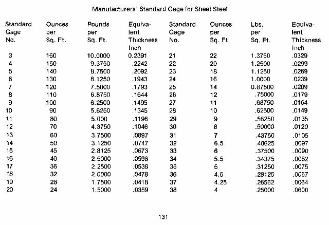
Manufacturers' Standard Gage for Sheet Steel
Standard Gage No.
Ounces Per Sq. Ft.
Pounds Per Sq. Ft.
Equiva- lent Thickness lnch 0.2391 .2242 .2092 .I 943 .I 793 .I644 .I495 .I 345 .I196 .lo46 .0897 .0747 .0673 .0598 .0538 .0478 .0418 .0359
Standard Gage No.
Ounces Per Sq. Ft.
Lbs. Per Sq. Ft.
Equiva- lent Thickness lnch .0329 .0299 .0269 .0239 .0209 .0179 .0164 .0149 .0135 .Of20 .0105 .0097 .0090 .0082 .0075 .0067 .0064 ,0600

SAE Number 1006 1008 1010 1015 1016 1017 1018 1019 1 om 1021 1022 1024 1025 1026 1027 1030 1033 1034 1 035 1 036 1038 1039
AlSl Number C1006 C1008 C1010 C1015 C1016 C1017 C1018 C1019 C1020 C1021 C1022 C1024 C1025 C1026 C1027 C1030 C1033 C1034 C1035 C1036 C1038 C1039
Chemical Compositions of SAE Standard Steels Carbon Manganese Phos- C MN phorus P (Max) 0.08 max. 0.25-0.40 0.040 0.10 max. 0.25-0.50 0.040 0.08-0.13 0.30-0.60 0.040 0.13-0.18 0.30-0.60 0.040 0.13-0.18 0.60-0.90 0.040 0.15-0.20 0.30-0.60 0.040 0.15-0.20 0.60-0.90 0.040 0.15-0.20 0.70-1 .OO 0.040 0.18-0.23 0.30-0.60 0.040 0.18-0.23 0.60-0.90 0.040 0.18-0.23 0.70-1 .OO 0.040 0.19-0.25 1.35-1.65 0.040 0.22-0.28 0.30-0.60 0.040 0.22-0.28 0.60-0.90 0.040 0.22-0.29 1.20-1.50 0.040 0.28-0.34 0.60-0.90 0.040 0.30-0.36 0.70-1 .OO 0.040 0.32-0.38 0.50-0.80 0.040 0.32-0.38 0.60-0.90 0.040 0.30-0.37 1.20-1.50 0.040 0.35-0.42 0.60-0.90 0.040 0.37-0.44 0.70-1 .OO 0.040
Sulphur S (Max) 0.050 0.050 0.050 0.050 0.050 0.050 0.050 0.050 0.050 0.050 0.050 0.050 0.050 0.050 0.050 0.050 0.050 0.050 0.050 0.050 0.050 0.050

SAE Number
1040 1041 1042 1043 1045 1046 1049 1050 1052 1055 1060 1062 1064 1065 1066 1070 1074 1078 1080 1085 1086 1090 1095
AlSl Number
Carbon C
0.37-0.44 0.36-0.44 0.40-0.47 0.40-0.47 0.43-0.50 0.43-0.50 0.46-0.53 0.48-0.55 0.47-0.55 0.50-0.60 0.55-0.65 0.54-0.65 0.60-0.70 0.60-0.70 0.60-0.71 0.65-0.75 0.70-0.80 0.72-0.85 0.75-0.88 0.80-0.93 0.82-0.95 0.85-0.98 0.90-1.03
Manganese MN
0.60-0.90 1.35-1.65 0.60-0.90 0.70-1 .OO 0.60-0.90 0.70-1 .OO 0.60-0.90 0.60-0.90 1.20-1.50 0.60-0.90 0.60-0.90 0.85-1.15 0.50-0.80 0.60-0.90 0.85-1 .I5 0.60-0.90 0.50-0.80 0.30-0.60 0.60-0.90 0.70-1 .OO 0.30-0.50 0.60-0.90 0.30-0.50
Phos- phorus P (Max)
Sulpher S (Max)
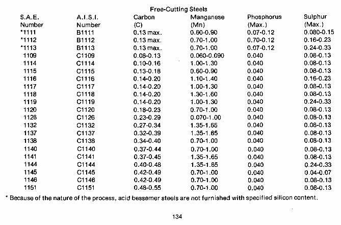
S.A.E. Number *I111
A.I.S.I. Number 81111 81112 81 11 3 C1109 C1114 C1115 C1116 C1117 C1118 C1119 C1120 C1126 C1132 C1137 C1138 C1140 C1141 C1144 C1145 C1146 C1151
Free-Cutting Steels Carbon Manganese (C) (Mn) 0.13 max. 0.60-0.90 0.13 max. 0.70-1 .OO 0.13 max. 0.70-1 .OO 0.08-0.13 0.060-0.090 0.10-0.16 1 .OO-1.30 0.13-0.18 0.60-0.90 0.14-0.20 1 .lo-1.40 0.14-0.20 1 .OO-1.30 0.14-0.20 1.30-1.60 0.14-0.20 1 .OO-1.30 0.18-0.23 0.70-1 .OO 0.23-0.29 0.070-1 .OO 0.27-0.34 1.35-1.65 0.32-0.39 1.35-1.65 0.34-0.40 0.70-1 .OO 0.37-0.44 0.70-1 .OO 0.37-0.45 1.35-1.65 0.40-0.48 1.35-1.65 0.42-0.49 0.70-1 .OO 0.42-0.49 0.70-1 .OO 0.48-0.55 0.70-1 .OO
Phosphorus (Max.) 0.07-0.12 0.70-0.12 0.07-0.1 2 0.040 0.040 0.040 0.040 0.040 0.040 0.040 0.040 0.040 0.040 0.040 0.040 0.040 0.040 0.040 0.040 0.040 0.040
Sulphur (Max.) 0.080-0.15 0.16-0.23 0.24-0.33 0.08-0.13 0.08-0.13 0.08-0.13 0.16-0.23 0.08-0.13 0.08-0.13 0.24-0.33 0.08-0.13 0.08-0.13 0.08-0.13 0.08-0.13 0.08-0.13 0.08-0.13 0.08-0.13 0.24-0.33 0.04-0.07 0.08-0.13 0.08-0.13
Because of the nature of the process, acid bessemer steels are not furnished with specified silicon content.

Manganese Steels
SAE Number
1320 1330 1 335 1340
231 7 2330 2340 2345 251 2 251 5 251 7
AlSl Number*
1320 1330 1225 1340
231 7 2330 2340 2345
E2512 251 5
E2517
Carbon C
0.18-0.23 0.28-0.33 0.33-0.38 0.38-0.43
0.15-0.20 0.28-0.33 0.38-0.43 0.43-0.48 0.09-0.14 0.12-0.17 0.15-0.20
Manganese Nickel Mn N i
Nickel Steels
Chromium Cr
.........
.........
.........
.........
.........
.........
.........
.........
.........
.........
Phos . P (Max.)
0.040 0.40 0.40 0.40
0.040 0.040 0.040 0.040 0.025 0.40 0.025
Sulphur S (Max.)
0.040 0.40 0.40 0.40
0.040 0.040 0.040 0.040 0.025 0.40 0.025
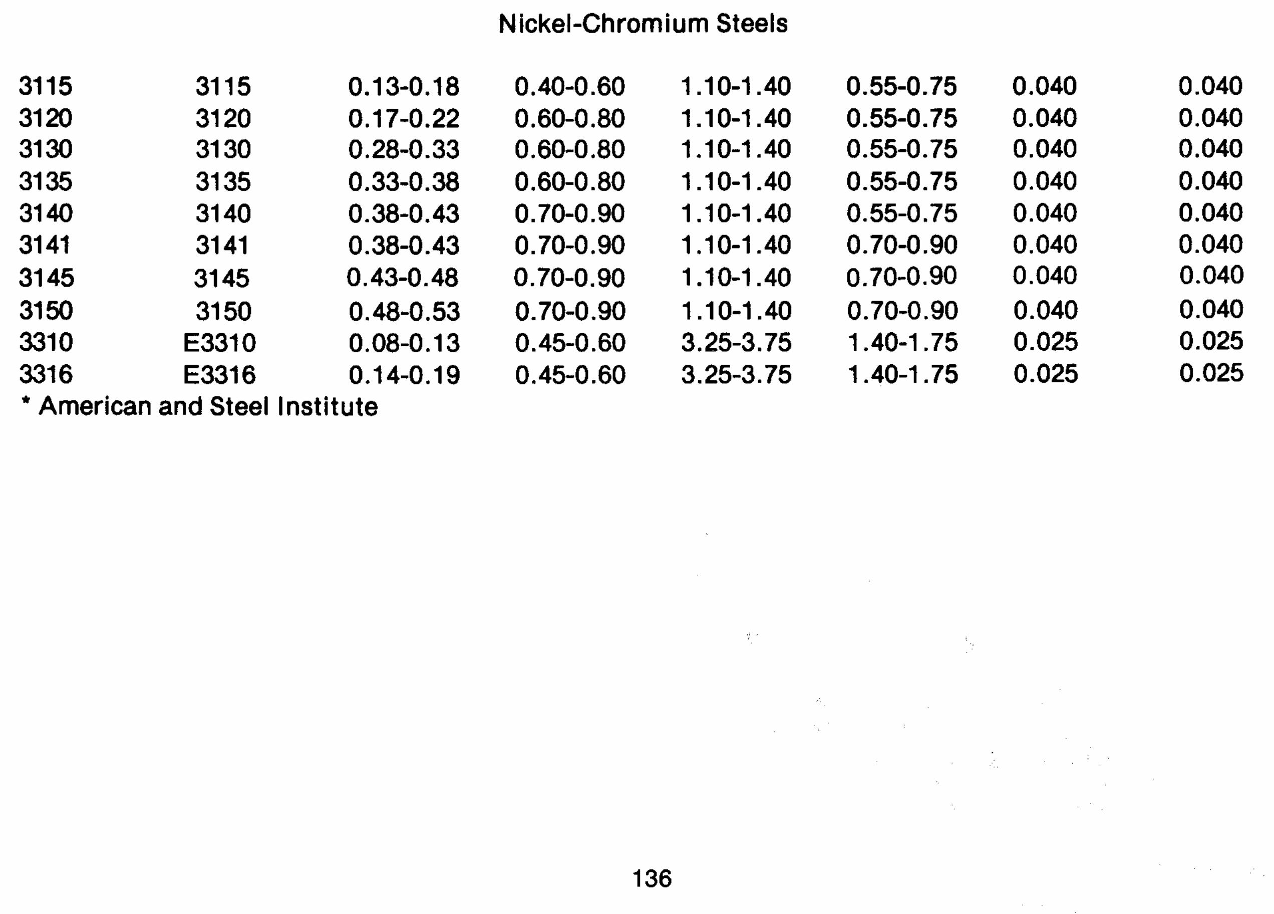

Molybdenum Steels
SAE No .
Carbon C
0.15-0.20 0.20-0.25 0.20-0.25 0.25-0.30 0.25-0.30 0.30-0.35 0.35-0.40 0.40-0.45 0.45-0.50 0.50-0.56 0.60-0.67 0.63-0.70 0.1 7-022 0.23-0.28 0.28-0.33 0.35-0.40 0.38-0.43 0.43-0.48 0.48-0.53 0.15-0.20
Manganese Mn
Nickel Ni
Chromium Cr
Moly . Mo

SAE No .
4320 4340 4608 461 5 461 7 4620
X4620 4621 4640 481 2 481 5 481 7 4820
Carbon C
0.17-0.22 0.38-0.43 0.06-0.11 0.13-0.18 0.15-0.20 0.17-0.22 0.18-0.23 0.18-0.23 0.38-0.43 0.10-0.15 0.13-0.18 0.15-0.20 0.18-0.23 -
Manganese M n
0.45-0.65 0.60-0.80 0.25-0.45 1.45-0.65 0.45-0.65 0.45-0.65 0.50-0.70 0.70-0.90 0.60-0.80 0.40-0.60 0.40-0.60 0.40-0.60 0.50-0.70
Nickel Ni
1.65-2.00 1.65-2 . 00 1.40-1.75 1.65-2.00 1.65-2.00 1.65-2.00 1.65-2.00 1.65-2.00 1.65-2.00 3.25-3.75 3.25-3.75 3.25-3.75 3.25-3.75
Chromium C r
0.40-0.60 0.70-0.90 ......... ......... ......... ......... ......... ......... ......... ......... ......... ......... .........
Moly . Mo
0.20-0.30 0.20-0.30 0.15-0.25 0.20-0.30 0.20-0.30 0.20-0.30 0.20-0.30 0.20-0.30 0.20-0.30 0.20-0.30 0.20-0.30 0.20-0.30
020-030

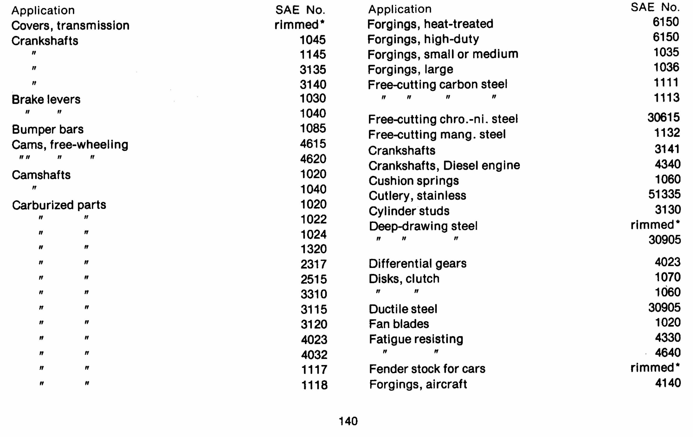
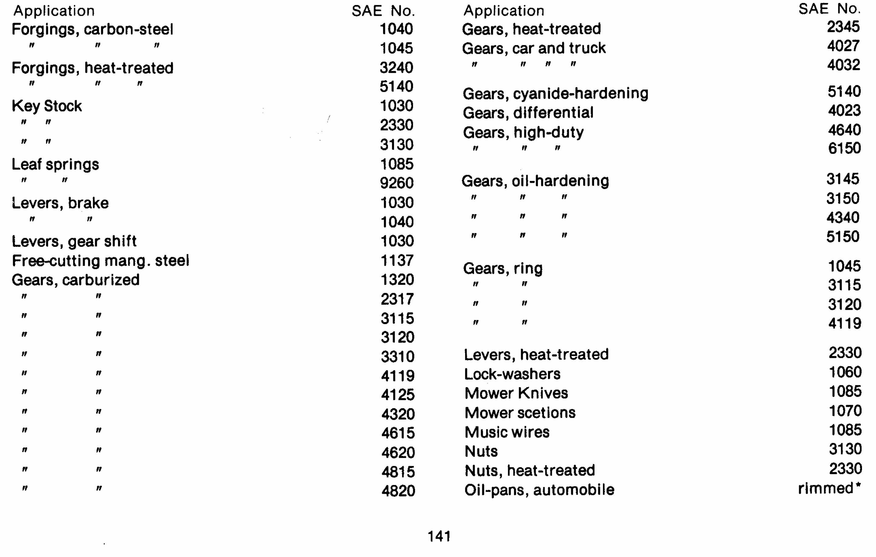

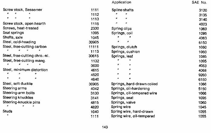
Application SAE No.
Screw stock, Bessemer n n I )
Screw stock, open hearth Screws, heat-treated Seat springs Shafts, axle Steel, cold-heading Steel, free-cutting carbon
II n n n
Steel, free-cutting chro.-ni. Steel, free-cutting mang.
n II rr n
Steel, minimum distortion n tt n
Steel, soft ductile Steering arms Steering-arm bolts Steering knuckles Steering-knuckle pins
n n n
Studs n
Spline shafts n n
Spring clips Springs, coil
n n
Springs, clutch Springs, cushion Springs, leaf
n n
n n
n n
I1 It
Springs, hard-drawn coiled Springs, oil-hardening Springs, oil-tempered wire Springs, seat Springs, valve Spring wire Spring wire, hard-drawn Spring wire, oil-tempered

Application
Stainless irons n rt
Steel, cold-rolled Studs, cold-headed Studs, cylinder Studs, heat-treated Studs, heavy-duty
n I1 I1
Tacks Thrust washers Thrust washers, oil-hardened Transmission shafts Tubing Tubing, front axle Tubing, seamless
SAE No.
51 21 0 51 71 0 1070 4042 31 30 2330 481 5 4820
rimmed* 1060 51 50 41 40 1040 41 40 1030
Application
Tubing, welded Universal joints Valve springs Washers, lock Welded structures Wire and rod Wire, cold-heading
n 11 II
Wire, hard-drawn spring n II 11 n
Wire, music Wire, oil-tempered spring Wrist-pins, automobile Yokes
SAE .No.
1020 1145 1060 1060
30705 killed*
rimmed* 1035 1045 1055 1085 1055 1020 1145
The rimmed and killed steels listed are in the SAE 1008. 1010. and 1015 group.