ijmeit// vol. 03 issue 2//february//page no: 997-1003 ...igmpublication.org/ijmeit issue/v3-i2/2...
TRANSCRIPT

Dr.Mohammad Miyan IJMEIT Volume 3 Issue 2 February 2015 Page 997
IJMEIT// Vol. 03 Issue 2//February//Page No: 997-1003//ISSN-2348-196x 2015
Infinitely Long Journal Bearing Under the Effect of Second Order Rotatory
Theory of Hydrodynamic Lubrication
Author
Dr. Mohammad Miyan
Associate Professor, Shia P.G. College, University of Lucknow, Lucknow,Uttar Pradesh, India -226020,
Email: [email protected]
ABSTRACT
In the present analysis the new equation of pressure is derived in the ascending powers of rotation number M
for the second order rotatory theory of hydrodynamic lubrication by the extended generalized Reynolds
equation, which gives some new excellent fundamental solutions with the help of pressure equation,
geometries, calculated tables and graphs for the infinitely long journal bearing including the negative
regions. The analysis of equation for pressure, the calculated values of pressure in the table and graphs
reveals that pressure is not independent of viscosity and increases slightly with viscosity. Also the pressure
increases with increasing values of the rotation number M. In the absence of rotation, the equation of
pressure gives the classical solutions of the classical theory of Osborne Reynolds for the hydrodynamic
lubrication.
Key words- Film thickness, Reynolds equation, Rotation number, Taylor’s number, Viscosity.
1. Introduction
1.1 Journal bearing:
In general the bearings [10, 11] can be divided in to
four categories:
1. Rolling element bearings for example;
ball, cylindrical, spherical or tapered roller
and needle etc.
2. Dry bearings for example; plastic
bushings, coated metal bushings etc.
3. Semi- lubricated bearings for example; oil-
impregnated bronze bushings etc.
4. Fluid film bearings for example;
crankshaft bearings etc.
Except from some radial-configuration aircraft
engines, almost all piston engines use fluid film
bearings [7]. This is true for the crankshaft and
sometimes in the camshaft, although often the
later runs directly in the engine structure. Here we
have to discuss the working of the fluid film
working and to demonstrate how engine designers
are reducing friction losses through bearing
technology [10]. The fluid film bearings operate by
generating, as a by-product of the relative motion
between the shaft and the bearing, a very thin film
of lubricant at a sufficiently high pressure to
match the applied load, as long as that load is
within the bearing capacity [1003]. Fluid film
bearings represent a form of scientific process, by
virtue of providing very large load carrying
capabilities in a compact, lightweight
implementation, and unlike the other classes, in
most cases can be designed for infinite life. The
fluid film bearings operate in any of the three
modes:
(a) Fully-hydrodynamic
(b) Boundary
(c) Mixed.
In fully hydrodynamic or "full- film"[7,11]
lubrication, the moving surface of the journal is
completely separated from the bearing surface by

Dr.Mohammad Miyan IJMEIT Volume 3 Issue 2 February 2015 Page 998
IJMEIT// Vol. 03 Issue 2//February//Page No: 997-1003//ISSN-2348-196x 2015
a very thin film of lubricant. The applied load
causes the centerline of the journal to be displaced
from the centerline of the bearing. This
eccentricity creates a circular "wedge" in the
clearance space.
The lubricant, by virtue of its viscosity, clings to
the surface of the rotating journal, and is drawn
into the wedge, creating a very high pressure,
which acts to separate the journal from the bearing
to support the applied load.
The bearing eccentricity is expressed as the
centerline displacement divided by the radial
clearance. The bearing eccentricity increases with
applied load and decreases with greater journal
speed and viscosity. The hydrodynamic pressure
has no relationship at all to the engine oil
pressure, except that if there is insufficient engine
oil pressure to deliver the required copious
volume of oil into the bearing, the hydrodynamic
pressure mechanism will fail and the bearing and
journal will be destroyed. The pressure
distribution in the hydrodynamic region of a fluid
film bearing increases from quite low in the large
clearance zone to its maximum at the point of
minimum film thickness for the incompressible
fluid like oil is pulled into the converging
"wedge" [4, 5] zone of the bearing. However, this
radial profile does not exist homogeneously across
the axial length of the bearing. If the bearing has
sufficient width, the profile will have a nearly flat
shape across the high-pressure region.
The second mode of bearing operation is
boundary lubrication. In boundary lubrication, the
"peaks" of the sliding surfaces i.e., journal and
bearing, are touching each other, but there is also
an extremely thin film of the lubricant only a few
molecules thick which is located in the surface
"valleys". That thin film tends to reduce the
friction from what it would be if the surfaces were
completely dry.
The mixed mode is a region of transition between
boundary and full- film lubrication. The surface
peaks on the journal and bearing surfaces partially
penetrate the fluid film and some surface contact
occurs, but the hydrodynamic pressure is starting
to increase.
When motion starts, the journal tries to climb on
the wall of the bearing due to the metal-to-metal
friction between the two surfaces.
If there is an adequate supply of lubricant, the
motion of the journal starts to drag the lubricant
into the wedge area and hydrodynamic lubrication
begins to occur along with the boundary
lubrication.
If we assume that the load and viscosity remain
relatively constant during this startup period, then
as revolution per minute increases, the
hydrodynamic operation strengthens until it is
fully developed and it moves the journal into its
steady state orientation. The direction of the
eccentricity and the minimum film thickness, do
not occur in line with the load vector and are
angularly displaced from the load.
There are also some other form of fluid-film
lubrication, which includes the squeeze-film
lubrication [10] i.e., the piston engine etc.
Squeeze-film action is based on the fact that a
given amount of time is required to squeeze the
lubricant out of a bearing axially, thereby adding
to the hydrodynamic pressure, and therefore to the
load capacity. Since there is little or no significant
rotating action in the wrist-pin bores, squeeze-film
hydrodynamic lubrication is the prevailing
mechanism which separates wrist pins from their
bores in the rods and pistons.
The figure-1 shows a hydrodynamic journal
bearing and a journal, are rotating in the clockwise
direction. The rotation of the journal causes
pumping of the lubricant that flows around the
bearing in the direction of rotation. If there is no
force applied to the journal then its position
remains unaltered and concentric to the bearing
position. The loaded journal moves from the
concentric position and forms converging gap
between the journal surfaces and bearing. Now the
movement of journal forced the lubricant to
squeeze through the gap generating the pressure.
The pressure falls to the cavitations pressure [10]
i.e., closer to the atmospheric pressure in the gap
in which the cavitations forms.

Dr.Mohammad Miyan IJMEIT Volume 3 Issue 2 February 2015 Page 999
IJMEIT// Vol. 03 Issue 2//February//Page No: 997-1003//ISSN-2348-196x 2015
Figure-1 (Hydrodynamic journal bearing)
Figure-2 (Forces acting on a unit volume of an
element of hydrodynamic lubrication film)
The figure-2 shows the forces act on an element of
the hydrodynamic film. In general the two types
of cavitations are form in the journal bearing.
(a) Gaseous cavitations: This is associated with
air and gases mixed with lubricant. If the pressure
of lubricant falls below the atmospheric pressure
then the gases come out to form the cavitations.
(b) Vapors cavitations: This is formed when the
load applied to the bearing fluctuates at the high
frequency. The pressure of fluid falls rapidly and
causes the cavitations due to fast evaporation.
Now the fluid pressure creates the supporting
force which separates the journal from the surface
of the bearing. The hydrodynamic force of friction
and force of fluid pressure counterbalance the
external load. So the position of journal can be
determined by these forces. In the hydrodynamic
regime, the journal climbs in the rotational
direction. If the working of journal is in the
boundary and mixed lubrication then the
hydrodynamic pressure ends and the journal
climbs in the opposite to the rotational direction.
1.2 Second Order Rotatory Theory of
Hydrodynamic Lubrication
In the theory of hydrodynamic lubrication, two
dimensional classical theories [4, 10] were first
given by Osborne Reynolds [11]. In 1886, in the
wake of a classical experiment by Beauchamp
Tower [12], he formulated an important differential
equation, which was known as: Reynolds
Equation [11]. The formation and basic mechanism
of fluid film was analyzed by that experiment on
taking some important assumptions given as:
(1.1) The fluid film thickness is very small as
compare to the axial and longitudinal dimensions
of fluid film.
(1.2) If the lubricant layer is to transmit pressure
between the shaft and the bearing, the layer must
have varying thickness.
Later Osborne Reynolds himself derived an
improved version of Reynolds Equation known
as: “Generalized Reynolds Equation” [7, 10], which
depends on density, viscosity, film thickness,
surface and transverse velocities. The rotation [1]
of fluid film about an axis that lies across the film
gives some new results in lubrication problems of
fluid mechanics. The origin of rotation can be
traced by certain general theorems related to
vorticity in the rotating fluid dynamics. The
rotation induces a component of vorticity in the
direction of rotation of fluid film and the effects
arising from it are predominant, for large Taylor’s
Number, it results in the streamlines becoming
confined to plane transverse to the direction of
rotation of the film.
The new extended version of “Generalized
Reynolds Equation” [7, 10] is said to be “Extended
Generalized Reynolds Equation”[1,3], which takes
into account of the effects of the uniform rotation
about an axis that lies across the fluid film and
depends on the rotation number M [1], i.e. the
square root of the conventional Taylor’s Number.
The generalization of the classical theory of
hydrodynamic lubrication is known as the
“Rotatory Theory of Hydrodynamic Lubrication” [1,3]. The “First Order Rotatory Theory of
Hydrodynamic Lubrication” and the “Second
Order Rotatory Theory of Hydrodynamic
Dr.Mohammad Miyan IJMEIT Volume 3 Issue 2 February 2015 Page 1000
IJMEIT// Vol. 03 Issue 2//February//Page No: 997-1003//ISSN-2348-196x 2015
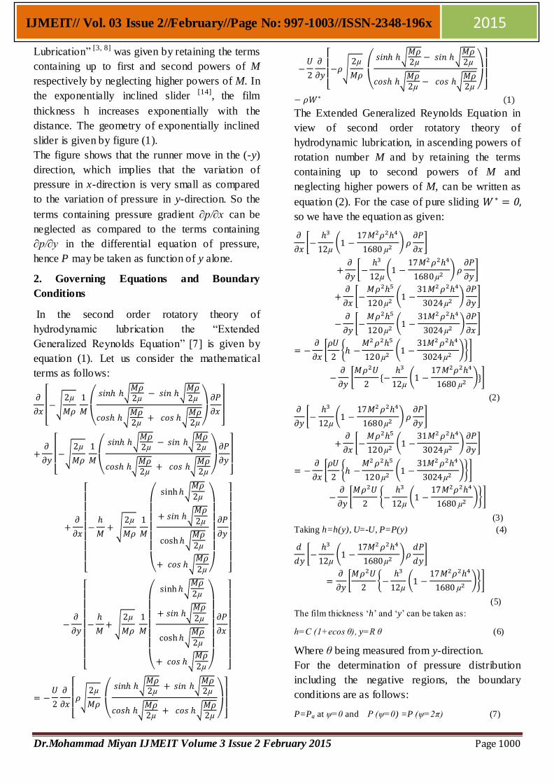
Lubrication” [3, 8] was given by retaining the terms
containing up to first and second powers of M
respectively by neglecting higher powers of M. In
the exponentially inclined slider [14], the film
thickness h increases exponentially with the
distance. The geometry of exponentially inclined
slider is given by figure (1).
The figure shows that the runner move in the (-y)
direction, which implies that the variation of
pressure in x-direction is very small as compared
to the variation of pressure in y-direction. So the
terms containing pressure gradient ∂p/∂x can be
neglected as compared to the terms containing
∂p/∂y in the differential equation of pressure,
hence P may be taken as function of y alone.
2. Governing Equations and Boundary
Conditions
In the second order rotatory theory of
hydrodynamic lubrication the “Extended
Generalized Reynolds Equation” [7] is given by
equation (1). Let us consider the mathematical
terms as follows:
The Extended Generalized Reynolds Equation in
view of second order rotatory theory of
hydrodynamic lubrication, in ascending powers of
rotation number M and by retaining the terms
containing up to second powers of M and
neglecting higher powers of M, can be written as
equation (2). For the case of pure sliding
so we have the equation as given:
(2)
(3)
Taking h=h(y), U=-U, P=P(y) (4)
(5)
The film thickness ‘h’ and ‘y’ can be taken as:
h=C (1+ecos θ), y=R θ (6)
Where θ being measured from y-direction.
For the determination of pressure distribution
including the negative regions, the boundary
conditions are as follows:
P=Pa at ψ=0 and P (ψ=0) =P (ψ=2π) (7)
Dr.Mohammad Miyan IJMEIT Volume 3 Issue 2 February 2015 Page 1001
IJMEIT// Vol. 03 Issue 2//February//Page No: 997-1003//ISSN-2348-196x 2015
3. Determination of Pressure:
Integrating equation (5) under the boundary
conditions (7), we get the equation for pressure
Where C1 and C2 are constants of integration and
ψ and θ are related by Sommerfeld substitutions.
With the help of boundary conditions, we have
C2=Pa
By considering the variable functions as follows:
The final equation for pressure distributions are
given as:
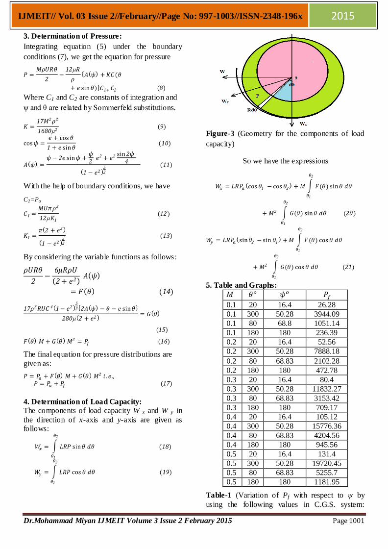
4. Determination of Load Capacity:
The components of load capacity W x and W y in
the direction of x-axis and y-axis are given as follows:
Figure-3 (Geometry for the components of load
capacity)
So we have the expressions
5. Table and Graphs:
M
0.1 20 16.4 26.28
0.1 300 50.28 3944.09
0.1 80 68.8 1051.14
0.1 180 180 236.39
0.2 20 16.4 52.56
0.2 300 50.28 7888.18
0.2 80 68.83 2102.28
0.2 180 180 472.78
0.3 20 16.4 80.4
0.3 300 50.28 11832.27
0.3 80 68.83 3153.42
0.3 180 180 709.17
0.4 20 16.4 105.12
0.4 300 50.28 15776.36
0.4 80 68.83 4204.56
0.4 180 180 945.56
0.5 20 16.4 131.4
0.5 300 50.28 19720.45
0.5 80 68.83 5255.7
0.5 180 180 1181.95
Table-1 (Variation of Pf with respect to ψ by
using the following values in C.G.S. system:

Dr.Mohammad Miyan IJMEIT Volume 3 Issue 2 February 2015 Page 1002
IJMEIT// Vol. 03 Issue 2//February//Page No: 997-1003//ISSN-2348-196x 2015
e=0.2, C=0.0067, R=3.35, U=500, ρ=0.9, µ=0.0002)
Figure-4 (Variation of Pf with respect to ψ by
using the following values in C.G.S. system: e=0.2, C=0.0067, R=3.35, U=500, ρ=0.9, µ=0.0002)
Figure-5 (Variation of Pf with respect to M by
using the following values in C.G.S. system: e=0.2, C=0.0067, R=3.35, U=500, ρ=0.9,
µ=0.0002)
6. Conclusions
The variation of pressure for infinitely long
journal bearings with respect to rotation number
M and ψ, when viscosity is constant; are shown by
table and graphs. Which show that in the second
order rotatory theory of hydrodynamic lubrication,
the pressure for infinitely long journal bearings
increases with increasing values of M, if viscosity
is taken as constant. The variation of pressure for
infinitely long journal bearings with respect to ψ
shows that it first increases up to a maximum
value from atmospheric pressure and then
decreases, as ψ varies from 0 to 2π, which are
shown by table and graphs. The equations for
pressure and load capacity also show that they are
not independent of viscosity µ and slightly
increase with µ, when M is constant. On taking
(M=0) in the expressions, we get the classical
solutions.
REFERENCES
1. M. B. Banerjee, R. S. Gupta, and A.P.
Dwivedi (1981) The Effects of Rotation in
Lubrication Problems, WEAR, 69, 205.
2. M. B. Banerjee, P. Chandra, and G. S. Dube
(1981) Effects of Small Rotation in Short
Journal Bearings, Nat. Acad. Sci. Letters,
Vol. 4, No.9.
3. M. B. Banerjee, G. S. Dube, K. Banerjee
(1982) The Effects of Rotation in
Lubrication Problems: A New Fundamental
Solutions, WEAR, 79, pp. 311-323.
4. A. Cameron (1981) Basic Lubrication
Theory, Ellis Harwood Limited, Coll.
House, Watergate, Chicester, p. 45-162.
5. Cameron, A. (1958) The Viscous Wedge
Trans., ASME, 1, 248.
6. S. Chandrasekhar (1970) Hydrodynamic and
Hydro magnetic Stability, Oxford University
Press, London, 83.
7. D. Dowson (1962) A Generalized Reynolds
Equations for Fluid Film Lubrication, Int. J.
Mech. Sci., 4, 159.
8. G. S. Dube and A. Chatterjee, (1988) Proc.
Nat. Acad. Sci. India, 58(58), I: 79.
0
5000
10000
15000
20000
25000
30000
0.1 0.2 0.3 0.4 0.5 M
P forθ=180
P forθ=80
P forθ=300
P forθ=20
0
5000
10000
15000
20000
25000
0 16.4 50.28 68.83 180 360
Pf
→
ψ →
M=0.1
M=0.2
M=0.3
M=0.4
M=0.5

Dr.Mohammad Miyan IJMEIT Volume 3 Issue 2 February 2015 Page 1003
IJMEIT// Vol. 03 Issue 2//February//Page No: 997-1003//ISSN-2348-196x 2015
9. J. Halling (1975) Principles of Tribology,
The Macmillan Press Ltd., London, 369.
10. Y. Hori (2005) Hydrodynamic Lubrication,
Springer Science & Business Media p.23-31.
11. O. Pinkus and B. Sternlicht (1961) Theory of
Hydrodynamic Lubrication, Mc. Graw Hill
Book Company, Inc. New York, 5-64.
12. O. Reynolds (1886) Phil. Trans. Roy. Soc.
London, Part I, 177.
13. O. Reynolds (1886) On the Theory of
Lubrication and its Application to Mr.
Beauchamp Tower’s Experiment, Phil.
Trans. Roy. Soc. London, 177 (I), 157.
14. E. A. Saibel and N. A. Macken (1973)
Annual Review of Fluid Mechanics, Inc.
Palo. Alto, Cal. Vol.5.
15. M. C. Shaw and E. F. Macks (1949)
Analysis and Lubrication of Bearings, Mc.
Graw Hill Book Company, Inc., New York.