ilc design, r&d plans and status - www … · mp9 clean room string assembly cavity string for...
TRANSCRIPT

Oct 30, 2008 9th ICFA Seminar
Global Design Effort 1Oct 30, 2008 9th ICFA Seminar
Global Design Effort 1
ILC Design, R&D Plans and Status
Ewan Patersonfrom
for the
GDE30-October-08

Oct 30, 2008 9th ICFA Seminar
Global Design Effort 2Oct 30, 2008 9th ICFA Seminar
Global Design Effort 2
Outline of Presentation
• Very brief history• Present status and plans of the global effort• Plans for 2009 and beyond• Status of R&D programs• Minimum Machine Design Studies• ILC/CLIC Collaboration• Conclusion

Oct 30, 2008 9th ICFA Seminar
Global Design Effort 3Oct 30, 2008 9th ICFA Seminar
Global Design Effort 3
ILC Reference Design
Detectors
Executive Summary
Accelerator
Physics
Oct 30, 2008 9th ICFA Semi nar
Global Design Effort 5Oct 30, 2008 9th ICFA Semi nar
Global Design Effort 5
RDR Design Parameters
Max. Center-of-mass energy 500 GeV
Peak Luminosity ~2x1034 1/cm2s
Beam Current 9.0 mA
Repetition rate 5 Hz
Average accelerating gradient 31.5 MV/m
Beam pulse length 0.95 ms
Total Site Length 31 km
Total AC Power Consumption ~230 MW
Published mid 2007

Oct 30, 2008 9th ICFA Seminar
Global Design Effort 4
ILC Reference Design
4
• High-gradient R&D
• Industrialisation• Mass-production

Oct 30, 2008 9th ICFA Seminar
Global Design Effort 5Oct 30, 2008 9th ICFA Seminar
Global Design Effort 5
ILC-GDE Organization Chart
SCRF-ML G-CFS AS
EU
AM
AS
ILCSC FALC
ILC-GDE Director
Regional Directors
Project Managers
AAP
PAC FALC-RG
Director’s Office= ~ Central Team = ~ EC
Experts
Project. M. Office- EDMS- Cost & Schedule- Machine Detector Interface- ILC, XFEL, Project X liaison- ILC Communications

Oct 30, 2008 9th ICFA Seminar
Global Design Effort 6Oct 30, 2008 9th ICFA Seminar
Global Design Effort 6
NEXT STEPS WERE TO
• Organise an increasing global effort
• Plan work towards an EDR in 2010
• Schedule work towards the EDR
• THEN CAME !@#$%^&* or

Oct 30, 2008 9th ICFA Seminar
Global Design Effort 7Oct 30, 2008 9th ICFA Seminar
Global Design Effort 7
BLACK DECEMBER 2007• Without warning there were severe budget
actions in the USA and the UK For ILC and many other science programs
• Many of the ILC R&D programs were stalled while future funding was clarified?
• Partial recovery during the 2008 with help from government agencies and collaborators. R&D continued at a reduced level.
• Based on future budget guidance from the funding agencies, FP7, etc, a new stretched two step global plan was developed :-
• TDP 1 by 2010 and TDP 2 by 2012

Oct 30, 2008 9th ICFA Seminar
Global Design Effort 8Oct 30, 2008 9th ICFA Seminar
Global Design Effort 8
TD Phase 1
• Timescale: Interim report mid 2010• Major theme: High-priority risk-mitigating
R&D and studies of cost reduction ideas– R&D demonstrations of critical items
– Minimum design -- top down cost/performance optimizaton to develop a new baseline by 2010
– Studies of governance models for a global project– Development of a site selection plan with ILCSC– Or how do we reduce the time to construction start and
therefore to physics results?

Oct 30, 2008 9th ICFA Seminar
Global Design Effort 9Oct 30, 2008 9th ICFA Seminar
Global Design Effort 9
• Timescale: Produce report in 2012• First goal: New baseline design
– SCRF – S1 Test of one RF unit
– Detailed technical design studies–
– Updated VALUE estimate and schedule
– Remaining critical R&D and technology demonstration
• Second Goal: Project Implementation Plan.
TD Phase 2

Oct 30, 2008 9th ICFA Seminar
Global Design Effort 10Oct 30, 2008 9th ICFA Seminar
Global Design Effort 10
R&D Plan - Technical Design Phase
• First Official Release June 08
• A 50 page document with details of all programs and schedules
• Next review and release:December 08
Global Design Effort

Oct 30, 2008 9th ICFA Seminar
Global Design Effort 11Oct 30, 2008 9th ICFA Seminar
Global Design Effort 11
R&D Program & Major Goals for TDP 1
SCRF• High Gradient R&D - globally coordinated program to demonstrate
gradient for TDP by 2010 with 50%yield; 90% yield by 2012• S1/S2 Cryomodule and RF Unit demonstrations
ATF-2 at KEK Demonstrate Fast Kicker performance and Final Focus Design which includes optics and tuning, instrumentation, feedback systems, alignment and stabilisation.
Electron Cloud Mitigation – (CesrTA)• Electron Cloud tests at Cornell to establish mitigation and verify one
damping ring is sufficient.
Minimum Machine Studies Studies of possible cost reduction designs and strategies forconsideration in a re-baseline in 2010
These topics comprise the rest of my talk

Oct 30, 2008 9th ICFA Seminar
Global Design Effort 12Oct 30, 2008 9th ICFA Seminar
Global Design Effort 12
Superconducting RF @ DESY
8/9 of these 1.3m 9cell cavities
13 m cryostat

Oct 30, 2008 9th ICFA Seminar
Global Design Effort 13Oct 30, 2008 9th ICFA Seminar
Global Design Effort 1313
SC Test Facility (STF) at KEK
Global Design Effort

Oct 30, 2008 9th ICFA Seminar
Global Design Effort 14Oct 30, 2008 9th ICFA Seminar
Global Design Effort 1414
SCRF Assembly Facility at FNAL
String Assembly MP9 Clean Room Cavity string for 1st CM
ICB clean: FinalAssembly fixtures installed
Global Design Effort

Oct 30, 2008 9th ICFA Seminar
Global Design Effort 15
These show the large size and infrastructure associated with ILC
SCRF facilities• Apologies for not including ALL the
Superconducting RF R&D Facilities at :-
• CORNELL• JLAB• TRIUMF• IHEP• SACLAY• CERN• ANL• ETC• ETC

Oct 30, 2008 9th ICFA Seminar
Global Design Effort 16Oct 30, 2008 9th ICFA Seminar
Global Design Effort 16
Status of 9-Cell Cavity R&DEurope
“Gradient” improved (<31.5> MV/m) with Ethanol rinse (DESY): Industrial (bulk) EP demonstrated (<36> MV/m) (DESY)Large-grain cavity (DESY)Surface process with baking in Ar-gas (Saclay)
America(s)Gradient distributed (20 – 40 MV/m) with various surface process (Cornell, JLab, Fermilab)Field emission reduced with Ultrasonic Degreasing using Detergent, and “Gradient” improved (JLab)
Asia“Gradient” demonstrated, 36MV/m (LL, KEK-JLab), and 28 MV/m(TESLA-like in cryomodule, KEK)
High gradients achieved in all regions but still with variable yield
16Global Design Effort

Oct 30, 2008 9th ICFA Seminar
Global Design Effort 17Oct 30, 2008 9th ICFA Seminar
Global Design Effort 17
Plan for High Gradient R&D
1: Research/find cause(s) of gradient limithigh resolution camera
surface analysis2: develop countermeasures
remove beads & pits, establish new surface proceeses
3: verify and integrate countermeasuresget statistics
4: allow controlled innovation plug compatibility
17Global Design Effort

Oct 30, 2008 9th ICFA Seminar
Global Design Effort 18Oct 30, 2008 9th ICFA Seminar
Global Design Effort 18
New High Resolution, Optical Inspection System
cameracamera
white LED half mirror
EL EL
mirror
motor & gear for mirror
camera & lens
sliding mechanism of camera
tilted sheet illuminationby Electro-Luminescence
perpendicular illumination by LED & half mirror
Camera system (7µm/pix) in 50mm diameter pipe.
For visual inspection of cavity inner surface.
~600µm beadson Nb cavity
18
Iwashita (Kyoto) and Hayano (KEK) et al.
Global Design Effort
DESY starting to use this system in cooperation with KEK

Oct 30, 2008 9th ICFA Seminar
Global Design Effort 19Oct 30, 2008 9th ICFA Seminar
Global Design Effort 19
Consistent with Thermometry done by FNAL/JLAB/KEK/Kyoto Team
54
62
1
3
87
Kyoto-camera found 3 spots in their exact location
~21mm
84µm height
60µm height
43µm height
19Global Design Effort

Oct 30, 2008 9th ICFA Seminar
Global Design Effort 20Oct 30, 2008 9th ICFA Seminar
Global Design Effort 20
Guideline: Standard Procedure and Feedback LoopStandardFabrication/Process
(Optional action)
Acceptance Test/Inspection
Fabrication Nb-sheet purchasing Chemical component analysis
Component (Shape) Fabrication Optical inspect., Eddy current
Cavity assembly with EBW (tumbling Optical inspection
Process EP-1 (Bulk: ~150um)
Ultrasonic degreasing (detergent) or ethanol rinse
High-pressure pure-water rinsing Optical inspection
Hydrogen degassing at 600 C (?) 750 C
Field flatness tuning
EP-2 (~20um)
Ultrasonic degreasing or ethanol (Flash/Fresh EP) (~5um))
High-pressure pure-water rinsing
General assembly
Baking at 120 C
Cold Test (vertical test)
Performance Test with temperature and mode measurement
Temp. mapping If cavity not meet specificationOptical inspection
20Global Design Effort

Oct 30, 2008 9th ICFA Seminar
Global Design Effort 21Oct 30, 2008 9th ICFA Seminar
Global Design Effort 21
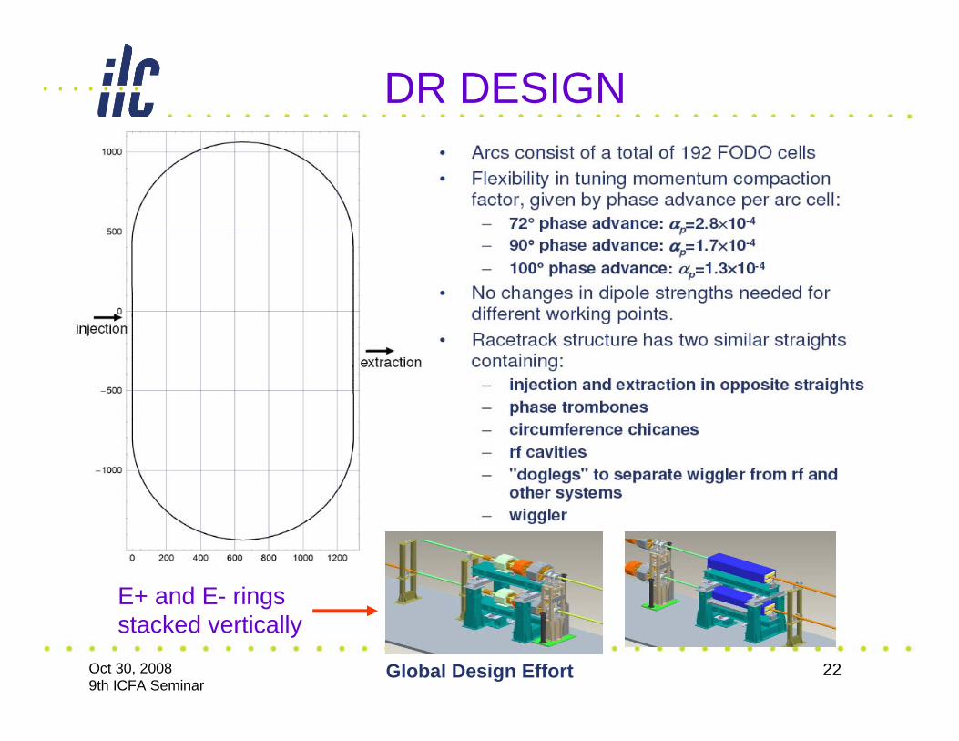
Damping Ring R&D• DR has a flexible race track design• 6.4 km Circumference with >1 km straights,
which contain, RF, Wigglers, Chicanes, Injection/ Extraction Systems
• Orientation could with straight parallel or at 90 degrees to the Linac-BDS beamline.
• There are two critical components which require a successful demonstration in TDP1
• Fast Inj/Ext Kickers• Suppression of E- Cloud in the E+ ring
Oct 30, 2008 9th ICFA Seminar
Global Design Effort 22
DR DESIGN
E+ and E- rings stacked vertically

Oct 30, 2008 9th ICFA Seminar
Global Design Effort 23
Fast Kicker R&D Program
• There are presently four strands to the R&D program:– SLAC/LLNL: Development of fast high-powerpulsers based on MOSFET technology.– SLAC/DTI: Development of fast high-power pulsers based on DSRD (drift step recovery diode) technology.– INFN-LNF: Tests of fast kickers in DAΦNE.– KEK: Tests of fast kickers in the ATF.
• Tests in DAΦNE and ATF are driven by machine upgrade plans (efficient beam
injection for DAΦNE and 30~60 multi-bunch train to ATF2 beam line), but are directly relevant for the damping rings R&D program.• So far, machine tests of fast kickers have relied on commercial (FID) pulser technologyand are incouraging.
Tests of MOSFET-based pulsershowpromising performance.
Tests of DSRD-based pulserusing board based on LLNLdesign (for MOSFET inductiveadder). Performance is limited by board design and components.

Oct 30, 2008 9th ICFA Seminar
Global Design Effort 24
Suppression of E- Cloud Effects• In electron or proton storage rings, low energy
electrons are accelerated by the high energy beam into the wall of the vacuum chamber where more electrons are emitted leading to the formation of an electron cloud.
• The formation and interaction of this cloud with the primary beam depends on the bunch charge density, bunch spacing, lattice functions, external magnetic or electric fields and the secondary emission coefficient of the vacuum chamber.
• To have confidence that this will not be a problem one must demonstrate experimentally the suppression of secondary emission and validate simulation codes in a variety of conditions.

Oct 30, 2008 9th ICFA Seminar
Global Design Effort 25
Electron Cloud R&D• Program of studies on suppressing the secondary
yield by modifying vacuum chamber surfaces, coatings or grooves, began on PEP11. This showed encouraging results, (TiN coated grooved chambers with secondary emission coefficients less than one)but was terminated along with the PEP11 program.(Black December)
• Still many questions left unanswered!
• Thanks to NSF/DOE CESRTA at Cornell was given a lease on life and these studies are now restarted as part of an intensive R&D program.

Oct 30, 2008 9th ICFA Seminar
Global Design Effort 26
CESR Reconfiguration• Electron Cloud Diagnostics
– L3 region prepped for arrival of PEP-II EC hardware including diagnostic chicane
Hardware being removed at SLACDelivery to Cornell in November
– New EC experimental regions in arcsw/ locations forcollaborator VCs
– L0 region reconfigured as a wiggler straight Instrumented with EC diagnosticsWiggler chambers with retarding field analyzers (fabricated at LBNL) - scheduledfor installation ~Oct 23rdChambers with EC mitigation (TiN coatings by SLAC)
CESRRing
L0Wiggler
CLEO
Re-commissioning for operations through Oct 27thCesrTA dedicated experiments: Oct 27-Nov 10Electron Cloud Experiments, Low EmittanceOperation, X-ray Beam Size Monitor

Oct 30, 2008 9th ICFA Seminar
Global Design Effort 27
EC Simulation Goals at CesrTA
• Understand cloud buildup in drift, quadrupole, dipole and wiggler sections of CesrTA, with different cloud suppression techniques.
• Understand interaction of the cloud and the beam in CesrTA, including instabilities and emittance growth.
• Validate cloud buildup and cloud dynamics simulations using CesrTA data, in order to develop confidence in the application of these simulations to predict cloud behavior in the ILC damping ring.
• Demonstrate cloud suppression techniques suitable for use in the ILC damping ring.
A very full program with a multinational team

Oct 30, 2008 9th ICFA Seminar
Global Design Effort 28
Accelerator Test Facility, ATF/ATF2.
Photo-cathode RF gun(electron source)
S-band LinacΔf ECS for multi-bunch beam
Extraction lineATF2 beam line (2008~) This a scaled down version of the ILC Beam Delivery System
Damping Ring

Oct 30, 2008 9th ICFA Seminar
Global Design Effort 29
ATF2 construction in 2007-2008
Assembly hall before constructionAssembly hall before construction Assembly hall emptied for constructionAssembly hall emptied for construction
Construction of shieldingConstruction of shieldingVacuum tube connected in Oct..
From extraction line to FF to be ready for Nov. beam commissioning
Construction of reinforced floorConstruction of reinforced floor

Oct 30, 2008 9th ICFA Seminar
Global Design Effort 30
Cavity BPMs, are just one example of Instrumentation R&D at ATF2
Cavity BPMs and front-end electronics modules will provide sub-micron resolution of beam position.
Cavity BPMs, for use with Q magnets with 100nm resolution (PAL, SLAC, KEK)
Prototype at PAL
C-band dipole mode Reference cavityDownmix to ~25MHz Digitize at ~100Ms/s, ~14 bit. 100 nanometer resolution. Large dynamic range >500um

Oct 30, 2008 9th ICFA Seminar
Global Design Effort 31
Minimum Machine: Current Definition
• “Minimum Machine” now refers to a set of identified options (elements) which may prove cost-effective
• Not a minimum in a definable sense– But a potential reduced-cost solutions…– with a potentially less margin
• An alternative design for study purposes– Comparison with RDR baseline– Cost (not performance) driven– options which were not studied during RDR phase
• Important to restrict options to manageable levels– available resources
31

Oct 30, 2008 9th ICFA Seminar
Global Design Effort 32
Minimum Machine Elements
1. Single-tunnel solution(s)
2. Klystron Cluster concept
3. Central region integration
4. Low beam power option
5. Single-stage compressor
6. Quantify cost of TeV upgrade support
7. “Value engineering”32

Oct 30, 2008 9th ICFA Seminar
Global Design Effort 33
Main Linac & Support Tunnel
• RDR (two-tunnel)– Access to equipment during
ops• Reliability/availability
• Shallow sites– Cut and cover like solutions– “service tunnel” on the
surface
• Single tunnel– European XFEL-like solution
• availability / reliability
33

Oct 30, 2008 9th ICFA Seminar
Global Design Effort 34
Klystron Cluster Concept
• RF power “piped”into accelerator tunnel
• Removal of service tunnel
• Access to klystrons & modulators maintained
• R&D needed to show power handling– Planned (SLAC,
KEK)
34SLAC
Feeds +/- 1 km of linac
Oct 30, 2008 9th ICFA Seminar
Global Design Effort 35
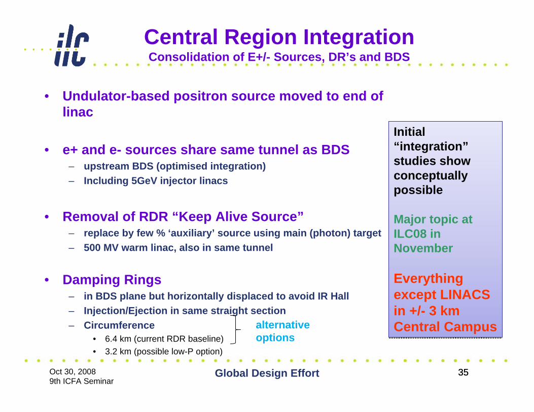
Central Region IntegrationConsolidation of E+/- Sources, DR’s and BDS
• Undulator-based positron source moved to end of linac
• e+ and e- sources share same tunnel as BDS– upstream BDS (optimised integration)– Including 5GeV injector linacs
• Removal of RDR “Keep Alive Source”– replace by few % ‘auxiliary’ source using main (photon) target– 500 MV warm linac, also in same tunnel
• Damping Rings– in BDS plane but horizontally displaced to avoid IR Hall– Injection/Ejection in same straight section – Circumference
• 6.4 km (current RDR baseline) • 3.2 km (possible low-P option)
alternative options
Initial “integration”studies show conceptually possible
Major topic at ILC08 in November
Everything except LINACS in +/- 3 km Central Campus
Initial “integration”studies show conceptually possible
Major topic at ILC08 in November
Everything except LINACS in +/- 3 km Central Campus
35

Oct 30, 2008 9th ICFA Seminar
Global Design Effort 36
RDR Parameter Plane Revisited
• RDR machine design around so-called “Parameter Plane”
• 1 nominal + 3 ‘scaled’ parameter sets representing various possible ‘performance issues’• Low charge – failure to
make single bunch charge• Low power – failure to
make number of bunches• Large σy – failure to make
emittance / vertical IP beam size
• As part of MM studies, review ‘parameter plane’ from a cost/performance issue
( )BSRF D y
y
L P H Dδηε
∝ ×
Main Linac $$$$
36

Oct 30, 2008 9th ICFA Seminar
Global Design Effort 37
Reduced Beam Power Option
• Reduce nb by factor of 2 (study scenario)– Maintain luminosity by pushing on beam-beam
• Similar to RDR Low-P parameter set, but• possible use of “travelling focus” concept
• “Minimum Cost” point of RDR parameter plane– Largest cost leverage of all sets in the table
• Spectrum of possible savings– ½ number of klystrons and modulators– reduced circumference damping ring (6.4 → 3.2km)– reduced associated CFS
37

Oct 30, 2008 9th ICFA Seminar
Global Design Effort 38
RDR Parameters Reviewed
Nom. RDR Low P RDR new Low P ECM (GeV) 500 500 500 Particles per bunch, N (×1010) 2.0 2.0 2.0Bunches per pulse, nb 2625 1320 1320 Pulse repetition rate (Hz) 5 5 5 Peak beam power, Pb (MW) 10.5 5.3 5.3 γεx (μm) 10 10 10γεy (nm) 40 36 36βx (cm) 2.0 1.1 1.1βy (mm) 0.4 0.2 0.2Traveling focus No No Yes σx (nm) 640 474 474σy (nm) 5.7 3.8 3.8 σz (μm) 300 200 300 Beamstrahlung* δE/E 0.023 0.045 0.036 Luminosity* (×1034 cm-2s-1) 2.0 1.7 1.9
38
SLAC

Oct 30, 2008 9th ICFA Seminar
Global Design Effort 39
Remaining MM Study Elements
• Single-stage compressor– Factor 20 bunch compression (σz ≥300μm @IP)– (RDR two-stage compressor with factor 45)
• Quantify cost of TeV upgrade support in RDR– Minimum length 500 GeV Ecm BDS– (High-power dumps?)
• Other “VALUE Engineering”– Water cooling– Vacuum solutions– Magnets & Power supplies– …
Encouraged activities
Considered parallel (on-going) to main ‘layout’discussions
(not primary cost drivers)
39

Oct 30, 2008 9th ICFA Seminar
Global Design Effort 40
(RDR ACD concepts and R&D)
Towards a Re-Baselining in 2010
• Process– RDR baseline & VALUE element are maintained
• Formal baseline– MM elements needs to be studied/reviewed
internationally• Regional balance in the AP&D groups involved• Regular meetings and discussions
– Formal review and re-baseline process beginning of 2010
• Exact process needs definition (a PM action item for 2009)• Community sign-off mandatory
MM def MM studies
2009 2010
New baseline engineering studies
2012Rejected elements
RDR Baseline (VALUE est.)
(RDR ACD concepts and R&D)
MM – Minimum Machine
RDR ACD – Alternate Configuration

Oct 30, 2008 9th ICFA Seminar
Global Design Effort 41
Joint ILC/CLIC R&D Areas
• ILC-CLIC working groups formed in 2008. Goal is to optimize use of resources in areas of common or overlapping interests.
- Civil Engineering and Conventional Facilities (CFS): Claude Hauviller/CERN, John Osborne/CERN, Vic Kuchler (FNAL)
- Beam Delivery Systems and Machine Detector Interface:D.Schulte/CERN, Brett Parker (BNL), Andrei Seryi (SLAC),, Emmanuel Tsesmelis/CERN
- Detectors: L.Linssen/CERN, Francois Richard/LAL, Dieter.Schlatter/CERN, Sakue Yamada/KEK
- Beam Dynamics: A.Latina/FNAL), Kiyoshi Kubo (KEK), D.Schulte/CERN, Nick Walker (DESY)
- Cost & Schedule: John Carwardine (ANL), Katy Foraz/CERN, Peter Garbincius (FNAL), Tetsuo Shidara (KEK), Sylvain Weisz/CERN
Project progress reports given at workshops such as CLIC08 14-17 Oct,08 and ILC08 15-20 Nov,08
Two new groups are being added, E+ sources, Damping Rings

Oct 30, 2008 9th ICFA Seminar
Global Design Effort 42
Conclusions• We have developed a “realistic” plan for the next
phase of the R&D and design of the ILC– A two stage ILC Technical Design Phase (TDP-1 2010 and
TDP-2 2012) is underway
• Overall Goals: Cost / Performance optimization through R&D program, developing a new baseline; complete a technical design and implementation plan on the time scale of LHC results
• After this wide range of studies of technical and civil options, and with results from the LHC, we will be ready with a solid design/cost/implementation plan to propose construction of an ILC that can be optimized for any proposed site.