im 155-6 pn hf interface module (6es7155-6au00 … · im 155-6 pn hf interface module...
TRANSCRIPT


IM 155-6 PN HF interface module
(6ES7155-6AU00-0CN0)
___________________
___________________
___________________
___________________
___________________
___________ ___________________
___________________
___________________
SIMATIC
ET 200SP IM 155-6 PN HF interface module (6ES7155-6AU00-0CN0)
Manual
12/2015 A5E03915895-AG
Preface
ET 200SP Documentation Guide
1
Product overview 2
Wiring 3
Parameters/address space 4
Interrupts, error messages, diagnostics and system alarms
5
Compatibility 6
Technical specifications 7
Dimension drawing A

Siemens AG Division Digital Factory Postfach 48 48 90026 NÜRNBERG GERMANY
A5E03915895-AG Ⓟ 12/2015 Subject to change
Copyright © Siemens AG 2013 - 2015. All rights reserved
Legal information Warning notice system
This manual contains notices you have to observe in order to ensure your personal safety, as well as to prevent damage to property. The notices referring to your personal safety are highlighted in the manual by a safety alert symbol, notices referring only to property damage have no safety alert symbol. These notices shown below are graded according to the degree of danger.
DANGER indicates that death or severe personal injury will result if proper precautions are not taken.
WARNING indicates that death or severe personal injury may result if proper precautions are not taken.
CAUTION indicates that minor personal injury can result if proper precautions are not taken.
NOTICE indicates that property damage can result if proper precautions are not taken.
If more than one degree of danger is present, the warning notice representing the highest degree of danger will be used. A notice warning of injury to persons with a safety alert symbol may also include a warning relating to property damage.
Qualified Personnel The product/system described in this documentation may be operated only by personnel qualified for the specific task in accordance with the relevant documentation, in particular its warning notices and safety instructions. Qualified personnel are those who, based on their training and experience, are capable of identifying risks and avoiding potential hazards when working with these products/systems.
Proper use of Siemens products Note the following:
WARNING Siemens products may only be used for the applications described in the catalog and in the relevant technical documentation. If products and components from other manufacturers are used, these must be recommended or approved by Siemens. Proper transport, storage, installation, assembly, commissioning, operation and maintenance are required to ensure that the products operate safely and without any problems. The permissible ambient conditions must be complied with. The information in the relevant documentation must be observed.
Trademarks All names identified by ® are registered trademarks of Siemens AG. The remaining trademarks in this publication may be trademarks whose use by third parties for their own purposes could violate the rights of the owner.
Disclaimer of Liability We have reviewed the contents of this publication to ensure consistency with the hardware and software described. Since variance cannot be precluded entirely, we cannot guarantee full consistency. However, the information in this publication is reviewed regularly and any necessary corrections are included in subsequent editions.

IM 155-6 PN HF interface module (6ES7155-6AU00-0CN0) 4 Manual, 12/2015, A5E03915895-AG
Preface
Purpose of the documentation This manual supplements the ET 200SP distributed I/O system (http://support.automation.siemens.com/WW/view/en/58649293) system manual.
Functions that generally relate to the system are described in this manual.
The information provided in this manual and in the system/function manuals supports you in commissioning the ET 200SP distributed I/O system.
Conventions Please also observe notes labeled as follows:
Note
A note contains important information on the product described in the documentation, on the handling of the product, or on the section of the documentation to which particular attention should be paid.
Security information Siemens provides products and solutions with industrial security functions that support the secure operation of plants, solutions, machines, equipment and/or networks. They are important components in a holistic industrial security concept. With this in mind, Siemens’ products and solutions undergo continuous development. Siemens recommends strongly that you regularly check for product updates.
For the secure operation of Siemens products and solutions, it is necessary to take suitable preventive action (e.g. cell protection concept) and integrate each component into a holistic, state-of-the-art industrial security concept. Third-party products that may be in use should also be considered. You can find more information about industrial security on the Internet (http://www.siemens.com/industrialsecurity).
To stay informed about product updates as they occur, sign up for a product-specific newsletter. You can find more information on the Internet (http://support.automation.siemens.com).

IM 155-6 PN HF interface module (6ES7155-6AU00-0CN0) Manual, 12/2015, A5E03915895-AG 5
Table of contents
Preface ................................................................................................................................................... 4
1 ET 200SP Documentation Guide ............................................................................................................. 6
2 Product overview .................................................................................................................................... 8
2.1 Properties .................................................................................................................................. 8
2.2 Functions ................................................................................................................................ 13 2.2.1 PROFIenergy .......................................................................................................................... 24 2.2.2 Configuration control (option handling) ................................................................................... 24 2.2.3 Use of fail-safe modules ......................................................................................................... 25 2.2.4 Multi Hot Swap ........................................................................................................................ 25
3 Wiring ................................................................................................................................................... 26
3.1 Pin assignment ....................................................................................................................... 26
3.2 Block diagram ......................................................................................................................... 31
4 Parameters/address space ................................................................................................................... 32
4.1 Parameters ............................................................................................................................. 32
4.2 Explanation of parameters ...................................................................................................... 32 4.2.1 Enable configuration control ................................................................................................... 32
4.3 Substitute value behavior ....................................................................................................... 33
4.4 Status of the supply voltage L+ of the I/O modules ................................................................ 34
5 Interrupts, error messages, diagnostics and system alarms ................................................................... 35
5.1 Status and error displays ........................................................................................................ 35
5.2 Interrupts ................................................................................................................................. 39 5.2.1 Triggering of a diagnostics interrupt ....................................................................................... 39 5.2.2 Triggering a hardware interrupt .............................................................................................. 40 5.2.3 Triggering of a remove/insert module interrupt ....................................................................... 40
5.3 Alarms ..................................................................................................................................... 41 5.3.1 Diagnostics alarms .................................................................................................................. 41 5.3.2 Maintenance events ................................................................................................................ 42 5.3.3 Channel diagnostics................................................................................................................ 42 5.3.4 Invalid configuration states of the ET 200SP on PROFINET IO ............................................ 46 5.3.5 Failure of supply voltage L+ at BaseUnit BU...D .................................................................... 46 5.3.6 STOP of the IO controller and recovery of the IO device ....................................................... 47
6 Compatibility ......................................................................................................................................... 48
6.1 Compatibility of modules ......................................................................................................... 48
7 Technical specifications ........................................................................................................................ 52
A Dimension drawing ............................................................................................................................... 59
IM 155-6 PN HF interface module (6ES7155-6AU00-0CN0) Manual, 12/2015, A5E03915895-AG 6
ET 200SP Documentation Guide 1
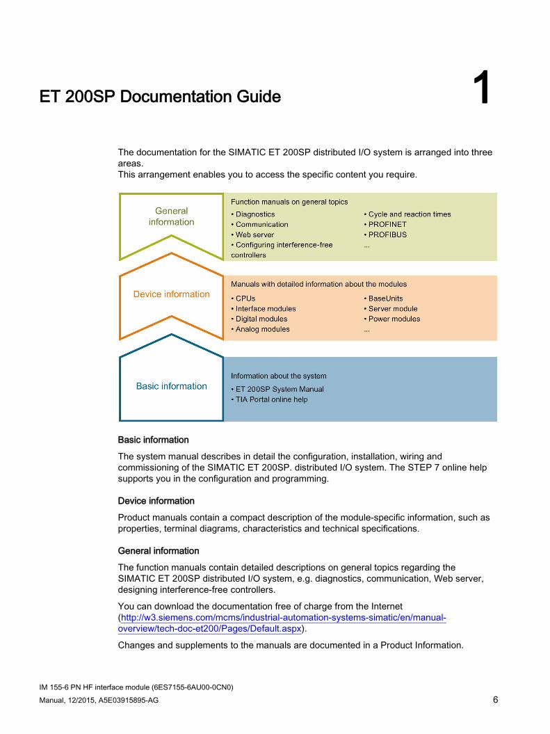
The documentation for the SIMATIC ET 200SP distributed I/O system is arranged into three areas. This arrangement enables you to access the specific content you require.
Basic information
The system manual describes in detail the configuration, installation, wiring and commissioning of the SIMATIC ET 200SP. distributed I/O system. The STEP 7 online help supports you in the configuration and programming.
Device information
Product manuals contain a compact description of the module-specific information, such as properties, terminal diagrams, characteristics and technical specifications.
General information
The function manuals contain detailed descriptions on general topics regarding the SIMATIC ET 200SP distributed I/O system, e.g. diagnostics, communication, Web server, designing interference-free controllers.
You can download the documentation free of charge from the Internet (http://w3.siemens.com/mcms/industrial-automation-systems-simatic/en/manual-overview/tech-doc-et200/Pages/Default.aspx).
Changes and supplements to the manuals are documented in a Product Information.

ET 200SP Documentation Guide
IM 155-6 PN HF interface module (6ES7155-6AU00-0CN0) Manual, 12/2015, A5E03915895-AG 7
Manual Collection ET 200SP The Manual Collection contains the complete documentation on the SIMATIC ET 200SP distributed I/O system gathered together in one file.
You can find the Manual Collection on the Internet (http://support.automation.siemens.com/WW/view/en/84133942).
My Documentation Manager The My Documentation Manager is used to combine entire manuals or only parts of these to your own manual. You can export the manual as PDF file or in a format that can be edited later.
You can find the My Documentation Manager on the Internet (http://support.industry.siemens.com/My/ww/en/documentation).
Application examples Applications examples support you with various tools and examples for solving your automation tasks. Solutions are shown in interplay with multiple components in the system - separated from the focus in individual products.
You can find application examples on the Internet (https://support.industry.siemens.com/sc/ww/en/sc/2054).
CAx Download Manager The CAx Download Manager is used to access the current product data for your CAx or CAe systems.
You configure your own download package with a few clicks.
In doing so you can select:
● Product images, 2D dimension drawings, 3D models, internal circuit diagrams, EPLAN macro files
● Manuals, characteristics, operating manuals, certificates
● Product master data
You can find the CAx Download Manager on the Internet (http://support.industry.siemens.com/my/ww/en/CAxOnline).
TIA Selection Tool With the TIA Selection Tool, you can select, configure and order devices for Totally Integrated Automation (TIA). This tool is the successor of the SIMATIC Selection Tool and combines the known configurators for automation technology into one tool. With the TIA Selection Tool, you can generate a complete order list from your product selection or product configuration.
You can find the TIA Selection Tool on the Internet (http://w3.siemens.com/mcms/topics/en/simatic/tia-selection-tool).

IM 155-6 PN HF interface module (6ES7155-6AU00-0CN0) Manual, 12/2015, A5E03915895-AG 8
Product overview 2 2.1 Properties
Article number 6ES7155-6AU00-0CN0
View of the module
Figure 2-1 View of the 155-6 PN HF interface module with accessories included in delivery

Product overview 2.1 Properties
IM 155-6 PN HF interface module (6ES7155-6AU00-0CN0) Manual, 12/2015, A5E03915895-AG 9
Properties The module has the following technical properties:
● Connects the ET 200SP distributed I/O system with PROFINET IO.
● Supply voltage 1L+ 24 V DC (SELV/PELV). The connection plug is included in the scope of delivery of the interface module.
● PROFINET IO connection via selectable BusAdapters
– For RJ45 bus connection plug (BA 2×RJ45)
– For direct connection of the bus cable (BA 2×FC)
– For fiber-optic cables POF/PCF (BA 2xSCRJ)
– For glass fiber-optic cable (BA 2xLC)
– As media converter for POF/PCF fiber-optic cable ⇔ standard RJ45 plug (BA SCRJ/RJ45)
– As media converter for POF/PCF fiber-optic cable ⇔ direct connection of the bus cable (BA SCRJ/FC)
– As media converter for glass fiber-optic cable ⇔ standard RJ45 plug (BA LC/RJ45)
– As media converter for glass fiber-optic cable ⇔ direct connection of the bus cable (BA LC/FC)
● As of firmware version V 3.0, you can plug a light-colored or a dark-colored BaseUnit into slot 1.
The module supports the following functions (see (Page 13))
Maximum configuration ● 64 ET 200SP I/O modules
● 1 m backplane bus (without interface module)
Note Incompatible I/O modules
A list of I/O modules that do not allow a configuration with more than 32 I/O modules is available in section Compatibility of modules (Page 48).
Product overview 2.1 Properties
IM 155-6 PN HF interface module (6ES7155-6AU00-0CN0) 10 Manual, 12/2015, A5E03915895-AG
Maximum amount of I/O data The maximum amount of I/O data without user data qualifier (net data) depends on the number and type of I/O modules used. From the maximum I/O data
● 1440 bytes or
● 1000 bytes with system redundancy S2
the bytes for the user data qualifier are deducted to determine the net data length. Note that modules/submodules that have no user data also have user data qualifiers.
The net data length is made up of:
● Maximum amount of I/O data including user data qualifiers (1440 byte/1000 bytes)
minus
● Number of I/O submodules with input or output data (in bytes)
minus
● 2 x number of I/O submodules with input and output data (in bytes)
minus
● 5 bytes without ET-Connection or 6 bytes with ET-Connection
Regardless of the type and number of I/O modules or module distribution to submodules, a minimum of the following I/O lengths can be used in total:
● 933 bytes (without system redundancy)
● 493 bytes (with system redundancy)
Note • The ET-Connection components must also be included for the I/O modules. • The result of the calculation of the maximum net data length applies equally to input and
output data. • In the case of a shared device configuration, the described calculations for the total I/O
data apply to all controllers that share the device. • If more than two (max. four) controllers share the device, the maximum amount of I/O
data including user data qualifier is limited to 360 bytes per controller.

Product overview 2.1 Properties
IM 155-6 PN HF interface module (6ES7155-6AU00-0CN0) Manual, 12/2015, A5E03915895-AG 11
Accessories The following accessories must be ordered separately:
● BA 2×RJ45 BusAdapter
● BA 2×FC BusAdapter
● BA 2×LC BusAdapter
● BA 2xSCRJ BusAdapter
● BA SCRJ/RJ45 BusAdapter
● BA SCRJ/FC BusAdapter
● BA LC/RJ45 BusAdapter
● BA LC/FC BusAdapter
● 24 V DC connector
● Labeling strips
● Reference identification label
You can find more information on accessories in the ET 200SP distributed I/O system (http://support.automation.siemens.com/WW/view/en/58649293) system manual.
Server module The server module is included in the scope of delivery of the interface module and available separately as an accessory.
The server module has the following properties:
● Terminates the backplane bus of the ET 200SP distributed I/O system
● Includes a holder for 3 spare fuses (5 × 20 mm)
● Provides station functions, for example, group load diagnostics, status bytes
● Identification data I&M 0 to 3
Note
You need to configure and assign parameters to the server module in the configuration software.
Place the server module in the last slot of the configuration. If there are 64 I/O modules, the server module is plugged in slot 65.
You can find more information in the Server module (http://support.automation.siemens.com/WW/view/en/63257531) manual.
Product overview 2.1 Properties
IM 155-6 PN HF interface module (6ES7155-6AU00-0CN0) 12 Manual, 12/2015, A5E03915895-AG
First BaseUnit of an ET 200SP in the configuration (as of V3.0)
Note First BaseUnit of an ET 200SP in the configuration
The first BaseUnit of an ET 200SP station may be a dark-colored one if an AC I/O module or AI Energy Meter ST is plugged. Please note the information on limiting the overvoltage and power rating in the AC I/O module manuals.
A light-colored BaseUnit must be plugged into the slot of the first 24 V DC I/O module in order to route the 24 V DC supply voltage via a fuse.
Pay attention to the type of the BaseUnits during the configuration.
As of firmware V3.x, the interface modules support plugging dark-colored BaseUnits in slot 1. This means that modules without a connection to the integrated voltage buses P1 and P2 can now also be configured starting with slot 1. Currently, this applies to the following modules:
● AI EnergyMeter
● DI 4x120..230VAC ST (6ES7131-6FD00-0BB1)
● DQ 4x24..230VAC/2A ST (6ES7132-6FD00-0BB1)
Requirement for configuration of these modules in slot 1:
● Configuration via GSD or GSDML
● Configuration as of STEP 7 V5.5 SP4 with
– HSP0241 V2.0 for IM155-6 PN ST
– HSP0242 V2.0 for IM155-6 DP HF
– HSP0255 V3.0 for IM155-6 PN HF
● Configuration as of STEP 7 V13 SP1

Product overview 2.2 Functions
IM 155-6 PN HF interface module (6ES7155-6AU00-0CN0) Manual, 12/2015, A5E03915895-AG 13
2.2 Functions
Introduction The interface module supports the following PROFINET IO functions:
● Integrated switch with 2 ports
● Supported Ethernet services: ping, arp, network diagnostics (SNMP)/MIB-2, LLDP-MIB and MRP-MIB
● Port diagnostics
● Disabling ports
● Minimum update time 250 µs
● Device replacement without programming device
● Reset to factory settings via PROFINET IO
● Firmware update via PROFINET IO
● Isochronous real-time communication
● Prioritized startup
● Media redundancy (MRP)
● Shared device
● Distribution of module channels to multiple submodules
● Module-internal or submodule-internal Shared Input/Shared Output (MSI/MSO)
● Media redundancy with planned duplication (MRPD)
● Isochronous mode
● System redundancy S2
● Station extension via ET-Connection
● The BusAdapter provides the connection system for PROFINET IO. The following versions are available for the IM 155-6 PN HF interface module:
BusAdapter Up to firmware 2.1
As of firmware 2.2
As of firmware 3.1
Firmware 3.3 or higher
For standard RJ45 connector: BA 2×RJ45
X X X X
For direct connection of the bus cable: BA 2×FC
X X X X
For fiber-optic cable (FOC): BA 2xSCRJ
-- X * X * X *

Product overview 2.2 Functions
IM 155-6 PN HF interface module (6ES7155-6AU00-0CN0) 14 Manual, 12/2015, A5E03915895-AG
BusAdapter Up to firmware 2.1
As of firmware 2.2
As of firmware 3.1
Firmware 3.3 or higher
For the transition from POF/PCF fiber-optic cable to RJ45 bus connection: BA SCRJ/RJ45
-- -- X * X *
For the transition from POF/PCF fiber-optic cable to the direct connection to the bus cable: BA SCRJ/FC
-- -- X * X *
For glass fiber-optic cable: BA 2xLC
- - - X *
For the transition from glass fiber-optic cable to RJ45 bus connection: BA LC/RJ45
- - - X *
For the transition from glass fiber-optic cable to the direct connection to the bus cable: BA LC/FC
- - - X *
* As of product version 3 of the interface module
The interface module supports additional functions:
● Identification data I&M 0 to I&M 4
● Device replacement without topological configuration
● Oversampling
● PROFIenergy
● Configuration control (option handling)
● Value status (quality information, QI) of I/O modules
● Use of fail-safe modules
● Multi Hot Swap (removal/insertion of multiple I/O modules during operation)
● Reset to factory settings via RESET button
Note
The use of the IM155-6 PN HF interface module as a docking unit (function: IO device changing in operation) in a docking system is not supported.

Product overview 2.2 Functions
IM 155-6 PN HF interface module (6ES7155-6AU00-0CN0) Manual, 12/2015, A5E03915895-AG 15
Requirements The table below shows the software requirements for a configuration with the IM 155-6 PN HF interface module:
Table 2- 1 Version dependencies of the module functions
Function Product version of
the module as of
Firmware version of
the module as of
Configuration software Configuration with
GSD file (http://support.automation.siemens.com/WW/view/en/19698639/130000)/ software from a
third-party manu-facturer 1
STEP 7 as of V5.5 SP3 with HSP 233
STEP 7 as of V5.5 SP4 with HSP 250/255
STEP 7 (TIA Portal) as of V12.0.1 with HSP 0058
Real-time communication 1 V2.0.0 X X X X Isochronous real-time communication
1 V2.0.0 X X X X
Prioritized startup 1 V2.0.0 X X X X Device replacement with-out programming device
1 V2.0.0 X X X X
Media redundancy (MRP) 1 V2.0.0 X X X X Shared device 1 V2.0.0 X X X X Value status 1 V2.0.0 X X X X PROFIenergy 1 V2.0.0 X X X X Multi Hot Swap 1 V2.0.0 X X X X Use of fail-safe modules 1 V2.0.0 - X X X Oversampling 1 V2.1.0 X X X X Media redundancy with planned duplication (MRPD)
1 V2.1.0 X --- --- ---
Isochronous mode 1 V2.1.0 --- X X X Module-internal Shared Input/Shared Output (MSI/MSO)
1 V2.2.0 X --- X X
BusAdapter for fiber-optic cable FOC: BA 2xSCRJ
3 V2.2.0 X --- X X (as of V13 SP1)
System redundancy S2 1 V3.0.0 X --- X --- Station extension via ET-Connection
1 V3.0.0 X --- X (as of V5.5 SP4)
X (as of V13 SP1)
Maximum user data length per module: 288 bytes
1 V3.1.0 X X (as of V5.5 SP4)
X (as of V5.5 SP4)
X (as of V13 SP1)
BA SCRJ/RJ45 BusAdapter
3 V3.1.0 X --- X (as of V5.5 SP4,
HSP0250 V3)
X (as of V13 SP1,
HSP0129 V1.0)

Product overview 2.2 Functions
IM 155-6 PN HF interface module (6ES7155-6AU00-0CN0) 16 Manual, 12/2015, A5E03915895-AG
Function Product version of
the module as of
Firmware version of
the module as of
Configuration software Configuration with
GSD file (http://support.automation.siemens.com/WW/view/en/19698639/130000)/ software from a
third-party manu-facturer 1
STEP 7 as of V5.5 SP3 with HSP 233
STEP 7 as of V5.5 SP4 with HSP 250/255
STEP 7 (TIA Portal) as of V12.0.1 with HSP 0058
BA SCRJ/FC BusAdapter 3 V3.1.0 X --- X (as of V5.5 SP4,
HSP0250 V3)
X (as of V13 SP1,
HSP0129 V1.0)
BA 2xLC BusAdapter 3 V3.3.0 X --- X (as of V5.5 SP4,
HSP0250/255 V4)
X (as of V13 SP1, Update
6)
LC/RJ45 BusAdapter 3 V3.3.0 X --- X (as of V5.5 SP4,
HSP0250/255 V4)
X (as of V13 SP1, Update
6)
BA LC/FC BusAdapter 3 V3.3.0 X --- X (as of V5.5 SP4,
HSP0250/255 V4)
X (as of V13 SP1, Update
6)
Distribution of module channels to multiple sub-modules
3 V3.3.0 X --- X (as of V5.5 SP4,
HSP0255 V4)
X (as of V13 SP1, Update
6) Maintenance interrupts of I/O modules
3 V3.3.0 X --- X (as of V5.5 SP4,
HSP0255 V4)
X (as of V13 SP1, Update
6) Extended Channel Diag-nostics
3 V3.3.0 X --- X (as of V5.5 SP4,
HSP0255 V4)
X (as of V13 SP1, Update
6) 1 Systems of third-party manufacturers: Depending on the range of functions of the third-party system
Cabling with fixed connection setting If you set a fixed connection setting of the port in STEP 7, you must also disable "Autonegotiation/Autocrossover".
You can find more information on this topic in the STEP 7 online help and:
● As of STEP 7 V12, in the function manual PROFINET with STEP 7 V13 (http://support.automation.siemens.com/WW/view/en/49948856).
● As of STEP 7 V5.5, in the system manual PROFINET System Description (http://support.automation.siemens.com/WW/view/en/19292127).

Product overview 2.2 Functions
IM 155-6 PN HF interface module (6ES7155-6AU00-0CN0) Manual, 12/2015, A5E03915895-AG 17
Real-time communication A transmission method for PROFINET IO based on cyclic data exchange with a provider-consumer model.
Isochronous real-time communication Synchronized transmission method for cyclic exchange of IRT data between PROFINET devices. A reserved bandwidth within the send clock is available for IRT data. The reserved bandwidth ensures that the IRT data can also be transferred without being affected by another high network load (e.g. TCP/IP communication or additional real time communication) at reserved, chronologically synchronized intervals.
A topological configuration is required for IRT.
Note IO controller as sync master with IRT communication
We recommend also operating the IO controller as a sync master when configuring the IRT communication.
Otherwise, IO devices with IRT and RT configuration could fail as a result of sync master failure.
You can find more information on the configuration of synchronized PROFINET devices in sync domains in the STEP 7 online help and:
● As of STEP 7 V12, in the function manual PROFINET with STEP 7 V13 (http://support.automation.siemens.com/WW/view/en/49948856).
● As of STEP 7 V5.5, in the system manual PROFINET System Description (http://support.automation.siemens.com/WW/view/en/19292127).

Product overview 2.2 Functions
IM 155-6 PN HF interface module (6ES7155-6AU00-0CN0) 18 Manual, 12/2015, A5E03915895-AG
Isochronous mode of I/O data I/O data, transmission cycle via PROFINET IO, and the user program are synchronized to achieve maximum deterministics. The input and output data of distributed I/O modules in the system is simultaneously collected and simultaneously output. The constant PROFINET IO cycle forms the corresponding clock generator. The interface module supports isochronous mode of I/O data for the modules starting at 250 µs. The IO device can exchange isochronous process data with a maximum of one IO controller.
Note
If the IO controller cannot access a module (for example, module pulled, activated configuration control without written control data record), cycle time violations may occur with activated isochronous mode in the synchronous cycle interrupt OB (OB61). The time error OB (OB80) is called in the event of a cycle time violation.
This behavior is associated with updating the process image by means of the "SYNC_PI" (SFC126) and "SYNC_PO" (SFC127) instructions and depends, among other things, on the set cycle time and the configuration limits.
Note Isochronous mode restrictions with IM 155-6 PN HF
Isochronous mode of I/O data in combination with the following functions is not possible with the interface module IM 155-6 PN HF: • Shared device • PROFIenergy
You can find more information on this topic in the STEP 7 online help and
● As of STEP 7 V12, in the function manual PROFINET with STEP 7 V13 (http://support.automation.siemens.com/WW/view/en/49948856).
● As of STEP 7 V5.5, in the system manual PROFINET System Description (http://support.automation.siemens.com/WW/view/en/19292127).

Product overview 2.2 Functions
IM 155-6 PN HF interface module (6ES7155-6AU00-0CN0) Manual, 12/2015, A5E03915895-AG 19
Prioritized startup Prioritized startup describes the PROFINET IO functionality for accelerating the startup of IO devices in a PROFINET IO system with IRT and RT communication.
The function reduces the time that the appropriately configured IO devices require in order to return to cyclic user data exchange in the following cases:
● After the supply voltage has returned
● After a station has returned
● After IO devices have been activated
Note
Dependency of the startup time
The interface module permits startup times from 0.5 s.
The startup time depends on the number and type of modules.
You can find more information on this topic in the STEP 7 online help and:
● As of STEP 7 V12, in the function manual PROFINET with STEP 7 V13 (http://support.automation.siemens.com/WW/view/en/49948856).
● As of STEP 7 V5.5, in the system manual PROFINET System Description (http://support.automation.siemens.com/WW/view/en/19292127).

Product overview 2.2 Functions
IM 155-6 PN HF interface module (6ES7155-6AU00-0CN0) 20 Manual, 12/2015, A5E03915895-AG
Device replacement
Device replacement without topological configuration
The device name is also stored on the BusAdapter in addition to the interface module. A device name saved on the BusAdapter is the requirement for device replacement without topological configuration.
Storing the name on the BusAdapter and the interface module produces a range of scenarios for using the device name when the interface module is replaced.
Table 2- 2 Scenarios for using the device name
Interface module empty Interface module with device name BusAdapter empty No device name available The device name from the interface module is used
and copied to the BusAdapter. BusAdapter with device name
The device name from the BusAdapter is used and copied to the interface module.
The device name from the BusAdapter is used and copied to the interface module if this has a different device name.
Be aware of the following constraints:
● Resetting to factory settings deletes the device name in both the interface module and the BusAdapter. To prevent the device name from being deleted in the BusAdapter, you can remove the BusAdapter from the interface module before resetting to factory settings.
● When a BusAdapter is replaced, a device name stored in the BusAdapter is applied to the interface module after a POWER ON.
● Do not pull/plug the BusAdapter while under voltage. If you pull/plug the BusAdapter while under voltage, the interface module restarts.
Device replacement with topological configuration
IO devices with this function can be replaced in a simple manner:
● The device name does not have to be assigned with the programming device.
The replacement IO device is assigned the device name by the IO controller and not by the programming device. The IO controller uses the configured topology and the neighboring relationships determined by the IO devices for this purpose. All involved devices must support the LLDP protocol (Link Layer Discovery Protocol). The configured target topology must match the actual topology.
IO devices that have already been used in another configuration should be reset to their factory settings before reuse (see system manual ET 200SP distributed I/O system (http://support.automation.siemens.com/WW/view/en/58649293)).
You can find more information on this topic in the STEP 7 online help and:
● As of STEP 7 V12, in the function manual PROFINET with STEP 7 V13 (http://support.automation.siemens.com/WW/view/en/49948856).
● As of STEP 7 V5.5, in the system manual PROFINET System Description (http://support.automation.siemens.com/WW/view/en/19292127).

Product overview 2.2 Functions
IM 155-6 PN HF interface module (6ES7155-6AU00-0CN0) Manual, 12/2015, A5E03915895-AG 21
Replacement of an IM 155-6 PN HF In a replacement scenario, any IO devices in operation must be reset to their as-delivered state via "Reset to factory settings" (see the system manual ET 200SP distributed I/O system (http://support.automation.siemens.com/WW/view/en/58649293)).
Media redundancy (MRP) Function for safeguarding communication and plant availability. A ring topology ensures that an alternative communication path is made available if a transmission route fails.
You can find more information on this topic in the STEP 7 online help and:
● As of STEP 7 V12, in the function manual PROFINET with STEP 7 V13 (http://support.automation.siemens.com/WW/view/en/49948856).
● As of STEP 7 V5.5, in the system manual PROFINET System Description (http://support.automation.siemens.com/WW/view/en/19292127).
Media redundancy with planned duplication (MRPD) If media redundancy is to be reached with short update times (together with IRT), you must use the MRP extension "Media redundancy with planned duplication (MRPD)".
The MRPD media redundancy function is enabled for the interface module IM 155-6 PN HF (V2.1):
● With the GSD file as of V5.5 SP3
You can find more information on this topic in the STEP 7 online help and:
● As of STEP 7 V12, in the function manual PROFINET with STEP 7 V13 (http://support.automation.siemens.com/WW/view/en/49948856).
● As of STEP 7 V5.5, in the system manual PROFINET System Description (http://support.automation.siemens.com/WW/view/en/19292127).

Product overview 2.2 Functions
IM 155-6 PN HF interface module (6ES7155-6AU00-0CN0) 22 Manual, 12/2015, A5E03915895-AG
Shared device IO device that makes its data available to up to four IO controllers.
The interface module supports shared device at submodule level.
If there is no validity check of the shared device projects by the Engineering System, note the following:
● Make sure the configurations are consistent. In particular, modules or submodules may only be assigned to one controller. Multiple assignment will result in an error; the module or submodule will only be available in the first controller.
● If you reconfigure the shared device configurations without the validity check mentioned above, you must commission the ET 200SP once again. This means that you have to reload the projects of all involved IO controllers to the specific CPU after reconfiguration and, if necessary, switch the interface module POWER OFF/POWER ON.
You can find more information on this topic in the STEP 7 online help and:
● As of STEP 7 V12, in the function manual PROFINET with STEP 7 V13 (http://support.automation.siemens.com/WW/view/en/49948856)
● As of STEP 7 V5.5, in the system manual PROFINET System Description (http://support.automation.siemens.com/WW/view/en/19292127).
Note
In the case of a shared device application, make sure that all controllers work with the same send clock. If controllers do not have the same send clock, the differing send clock can result in communication relationships that are not set up.
If you set up all controllers in one project, the same send clock is ensured. Set the same send clock for engineering in separate projects.
Submodules The IM 155-6 PN HF interface module supports the division of I/O modules into up to 4 submodules. This allows parts of an I/O module to be separately configured and parameterized.
A maximum of 256 submodules is supported, whereby 4 submodules are used for the interface module and one submodule for the server module.
It is possible to assign each of these submodules to different IO controllers.
The functions:
● Firmware update
● Write I&M data
● Calibration
● PROFIenergy
can only be executed if you have configured submodule 1 during configuration.

Product overview 2.2 Functions
IM 155-6 PN HF interface module (6ES7155-6AU00-0CN0) Manual, 12/2015, A5E03915895-AG 23
Module-internal Shared Input/Shared Output (MSI/MSO) The Module-internal Shared Input function allows an input module to make its input data available to up to four IO controllers. Each controller has read access to the same channels.
The Module-internal Shared Output function allows an output module to be operated by up to four IO controllers. One IO controller has write access. Up to three additional IO controllers can have read access to the same channels.
You can find more information on this topic in the STEP 7 online help and:
● As of STEP 7 V12, in the function manual PROFINET with STEP 7 V13 (http://support.automation.siemens.com/WW/view/en/49948856)
Value status The IM 155-6 PN HF interface module supports I/O modules with value status.
Additional information on the value status can be found in the manuals for the I/O modules.
Oversampling The IM 155-6 PN HF interface module supports the Oversampling mode of HS modules. With oversampling, the modules reduce the respective PROFINET send clocks in isochronous mode.
Additional information on oversampling can be found in the manuals for the I/O modules.
Compatibility with IM 155-6 PN interface module In an existing plant, the IM 155-6 PN HF replaces the IM 155-6 PN ST without reconfiguration. When the IM 155-6 PN HF replaces the IM 155-6 PN ST, it is possible to insert and remove several I/O modules during operation.
For more information on compatibility, refer to section: Compatibility (Page 48)
Product overview 2.2 Functions
IM 155-6 PN HF interface module (6ES7155-6AU00-0CN0) 24 Manual, 12/2015, A5E03915895-AG
2.2.1 PROFIenergy
Properties PROFIenergy (for PROFINET) reduces the energy consumption by using PROFIenergy commands during production-free periods.
Reference You can find more information on PROFIenergy in the:
● I/O modules (http://support.automation.siemens.com/WW/view/en/55679691/133300) manual.
● Function manual PROFINET with STEP 7 V13 (http://support.automation.siemens.com/WW/view/en/49948856).
● PROFINET System Description (http://support.automation.siemens.com/WW/view/en/19292127) system manual.
● PROFIenergy (http://support.automation.siemens.com/WW/view/en/66928686) product information.
● Internet (http://www.profibus.com) under Common Application Profile PROFIenergy; Technical Specification for PROFINET; Version 1.0; January 2010; Order No: 3.802.
2.2.2 Configuration control (option handling)
Properties Configuration control allows you to prepare your automation system for future expansions or changes. Configuration control means you can configure the planned maximum expansion of your automation system in advance and flexibly vary it later by means of the user program.
Reference You can find more information on configuration control ● System manual ET 200SP distributed I/O system
(http://support.automation.siemens.com/WW/view/en/58649293) ● on the Internet under the following link: Application collection
(http://support.automation.siemens.com/WW/view/en/29430270). ● in the STEP 7 online help.

Product overview 2.2 Functions
IM 155-6 PN HF interface module (6ES7155-6AU00-0CN0) Manual, 12/2015, A5E03915895-AG 25
2.2.3 Use of fail-safe modules
Properties The IM 155-6 PN HF interface module as of V2.0 firmware supports the use of fail-safe modules.
Reference You can find more information in the ET 200SP distributed I/O system (http://support.automation.siemens.com/WW/view/en/58649293) system manual.
2.2.4 Multi Hot Swap
Properties You can remove and insert any number of I/O modules during operation. The interface module and the inserted I/O modules remain in operation.
Note
The IM 155-6 PN HF interface module does not support the removal and insertion of the server module, the interface module and BusAdapter during operation.
Reference You can find more information on the removal/insertion of modules in the system manual ET 200SP distributed I/O system (http://support.automation.siemens.com/WW/view/en/58649293).

IM 155-6 PN HF interface module (6ES7155-6AU00-0CN0) 26 Manual, 12/2015, A5E03915895-AG
Wiring 3 3.1 Pin assignment
24 V DC supply voltage The following table shows the signal names and the descriptions of the pin assignment for a 24 V DC supply voltage.
Table 3- 1 Pin assignment 24 V DC supply voltage
View Signal name1 Description Connector IM connection
1L+ 24 V DC 2L+ 24 V DC (for looping through)2 1M Ground 2M Ground (for looping through)2
1 1L+ and 2L+ as well as 1M and 2M are bridged internally. 2 Maximum 10 A permitted.

Wiring 3.1 Pin assignment
IM 155-6 PN HF interface module (6ES7155-6AU00-0CN0) Manual, 12/2015, A5E03915895-AG 27
PROFINET IO with BusAdapter BA 2×RJ45 The following table shows the signal names and description of the pin assignment for the BA 2×RJ45 BusAdapter.
Table 3- 2 PROFINET IO pin assignment with BusAdapter BA 2×RJ45
View Signal name Description
1 TD Transmit data + 2 TD_N Transmit data – 3 RD Receive data + 4 GND Ground 5 GND Ground 6 RD_N Receive data – 7 GND Ground 8 GND Ground
PROFINET IO with BusAdapter BA 2×FC The following table shows the signal names and description of the pin assignment for the BA 2×FC BusAdapter.
Table 3- 3 PROFINET IO pin assignment with BusAdapter BA 2×FC
View Signal name Description
1 TD Transmit data + 2 TD_N Transmit data – 3 RD Receive data + 4 RD_N Receive data -

Wiring 3.1 Pin assignment
IM 155-6 PN HF interface module (6ES7155-6AU00-0CN0) 28 Manual, 12/2015, A5E03915895-AG
PROFINET IO with BusAdapter BA 2×SCRJ The following table shows the signal names and description of the pin assignment for the BA 2×SCRJ BusAdapter.
Table 3- 4 PROFINET IO pin assignment with BusAdapter BA 2×SCRJ
View Signal name
Description
① Receiver / Receive data
② Sender / Transmit data
PROFINET IO with BusAdapter BA SCRJ/RJ45 The following table shows the signal names and description of the pin assignment for the BA SCRJ/RJ45 BusAdapter.
Table 3- 5 PROFINET IO pin assignment with BusAdapter BA SCRJ/RJ45
View Signal name Description
① Receiver / Receive data
② Sender / Transmit data
1 TD Transmit data + 2 TD_N Transmit data – 3 RD Receive data + 4 GND Ground 5 GND Ground 6 RD_N Receive data – 7 GND Ground 8 GND Ground

Wiring 3.1 Pin assignment
IM 155-6 PN HF interface module (6ES7155-6AU00-0CN0) Manual, 12/2015, A5E03915895-AG 29
PROFINET IO with BusAdapter BA SCRJ/FC The following table shows the signal names and description of the pin assignment for the BA SCRJ/FC BusAdapter.
The pin assignment for the BA SCRJ/FC BusAdapter is shown individually for a clearer overview.
Table 3- 6 PROFINET IO pin assignment with BusAdapter BA SCRJ/FC
View Signal name Description
① Receiver / Receive data
② Sender / Transmit data
1 TD Transmit data + 2 TD_N Transmit data – 3 RD Receive data + 4 RD_N Receive data -
PROFINET IO with BusAdapter BA 2×LC The following table shows the signal names and description of the pin assignment for the BA 2×LC BusAdapter.
Table 3- 7 PROFINET IO pin assignment with BusAdapter BA 2×LC
View Signal name
Description
① Receiver / Receive data
② Sender / Transmit data
Wiring 3.1 Pin assignment
IM 155-6 PN HF interface module (6ES7155-6AU00-0CN0) 30 Manual, 12/2015, A5E03915895-AG
PROFINET IO with BusAdapter BA LC/RJ45 The following table shows the signal names and description of the pin assignment for the BA LC/RJ45 BusAdapter.
Table 3- 8 PROFINET IO pin assignment with BusAdapter BA LC/RJ45
View Signal name Description
① Receiver / Receive data
② Sender / Transmit data
1 TD Transmit data + 2 TD_N Transmit data – 3 RD Receive data + 4 GND Ground 5 GND Ground 6 RD_N Receive data – 7 GND Ground 8 GND Ground
PROFINET IO with BusAdapter BA LC/FC The following table shows the signal names and description of the pin assignment for the BA LC/FC BusAdapter.
The pin assignment for the BA LC/FC BusAdapter is shown individually for a clearer overview.
Table 3- 9 PROFINET IO pin assignment with BusAdapter BA LC/FC
View Signal name Description
① Receiver / Receive data
② Sender / Transmit data
1 TD Transmit data + 2 TD_N Transmit data – 3 RD Receive data + 4 RD_N Receive data -
Reference You can find more information on accessories and how to connect the interface module in the ET 200SP distributed I/O system (http://support.automation.siemens.com/WW/view/en/58649293) system manual.

Wiring 3.2 Block diagram
IM 155-6 PN HF interface module (6ES7155-6AU00-0CN0) Manual, 12/2015, A5E03915895-AG 31
3.2 Block diagram
Block diagram The following figure shows a block diagram of the interface module IM 155-6 PN HF.
① Switch L+ 24 V DC supply voltage ② ET 200SP backplane bus interface and electronics M Ground ③ Backplane bus LK 1,2 LED Link TX/RX ④ Internal power supply MT 1,2 LED FiberOptic (SCRJ port) X80 24 V DC Feed supply voltage RN LED RUN/STOP (green/yellow) X5 BusAdapter ER ERROR LED (red) P1 R PROFINET interface X1 Port 1 MT MAINT LED (yellow) P2 R PROFINET interface X1 Port 2 PWR POWER LED (red)
Figure 3-1 Block diagram of the IM 155-6 PN HF interface module

IM 155-6 PN HF interface module (6ES7155-6AU00-0CN0) 32 Manual, 12/2015, A5E03915895-AG
Parameters/address space 4 4.1 Parameters
Parameters for IM 155-6 PN HF interface module The following table shows the parameters for the interface module IM 155-6 PN HF.
Table 4- 1 Parameters for interface module IM 155-6 PN HF (GSD file)
Parameters Value range Default Efficiency range Enable configuration control Yes/No No ET 200SP
4.2 Explanation of parameters
4.2.1 Enable configuration control
Enable configuration control You can use this parameter to enable the configuration control function in the ET 200SP distributed I/O system.
Note
If you configure the enable, the ET 200SP distributed I/O system requires a control data record 196 from the user program in order for the ET 200SP distributed I/O system to operate the I/O modules.
Reference You can find more information on the control data record in the ET 200SP distributed I/O system (http://support.automation.siemens.com/WW/view/en/58649293) system manual and in the STEP 7 online help.

Parameters/address space 4.3 Substitute value behavior
IM 155-6 PN HF interface module (6ES7155-6AU00-0CN0) Manual, 12/2015, A5E03915895-AG 33
4.3 Substitute value behavior
Substitute value behavior The respective output behaves according to its configured substitute value behavior:
● Current-free/voltage-free
● Output substitute value
● Keep last value
The substitute value behavior is triggered in the following cases:
● STOP controller
● Controller failure (connection interrupted)
● Parameter assignment phase during startup
● Deactivating the IO device
● Station stop
– Missing server module
– Insertion of invalid I/O modules
– At least one I/O module installed on an incorrect BaseUnit
Note
Reducing a configuration
If you reduce the configuration of the ET 200SP distributed I/O system and download the configuration to the CPU, the modules which are no longer configured but still present retain their original substitute value behavior. This applies until the supply voltage is switched off at the interface module.
The "current-free/voltage-free" behavior becomes effective in the following cases:
● Firmware update
● Reset to factory settings
● Configuration control: The IM has not received a valid control data record 196 yet.
● Incorrectly configured module
● Module with incorrect parameter assignment
Substitute value behavior for module-internal Shared Output (MSO) and module-internal Shared Input (MSI)
Substitute value behavior for module-internal Shared Output (MSO) and module-internal Shared Input (MSI) corresponds to the behavior described above.

Parameters/address space 4.4 Status of the supply voltage L+ of the I/O modules
IM 155-6 PN HF interface module (6ES7155-6AU00-0CN0) 34 Manual, 12/2015, A5E03915895-AG
4.4 Status of the supply voltage L+ of the I/O modules The status of the supply voltage L+ of the ET 200SP I/O modules is mapped to the server module with the interface module IM 155-6 PN HF.
You can find information on the status of the supply voltage L+ of the I/O modules in the Server module (http://support.automation.siemens.com/WW/view/en/63257531) manual.

IM 155-6 PN HF interface module (6ES7155-6AU00-0CN0) Manual, 12/2015, A5E03915895-AG 35
Interrupts, error messages, diagnostics and system alarms 5 5.1 Status and error displays
LED displays The following figure shows the LED displays on the interface module and BusAdapter.
① RN (green) ② ER (red) ③ MT (yellow) ④ PWR (green) ⑤ MT2 (yellow) (SCRJ port) ⑥ LK2 (green) ⑦ MT1 (yellow) (SCRJ port) ⑧ LK1 (green)
Figure 5-1 LED displays on the interface module and BusAdapter

Interrupts, error messages, diagnostics and system alarms 5.1 Status and error displays
IM 155-6 PN HF interface module (6ES7155-6AU00-0CN0) 36 Manual, 12/2015, A5E03915895-AG
Meaning of the LED displays The following tables contain the meaning of the status and error displays.
RN/ER/MT LEDs on the interface module
Table 5- 1 Status and error displays of RN/ER/MT LEDs
LEDs Meaning
Solution RN
(RUN) ER
(ERROR) MT
(MAINT)
Off
Off
Off
Missing or insufficient supply voltage on interface module.
Check the supply voltage or turn it on at the interface module.*
On
On
On
Test of LEDs during startup: The three LEDs light up simultaneously for ap-proximately 0.25 s.
---
Flashes
Not relevant Not rele-vant
Interface module is deactivated. Activate the interface module with the con-figuration software or the user program.
Interface module is not configured. Configure the interface module with the configuration software.
ET 200SP starts up. --- ET 200SP is being assigned parame-ters. ET 200SP is being reset to factory settings.
On
Not relevant Not rele-vant
ET 200SP is currently exchanging data with the IO controller.
---
Not rele-vant
Flashes
Not rele-vant
Group errors and group error channels. Evaluate the diagnostics and eliminate the error.
The configured structure does not cor-respond to the actual structure of the ET 200SP .
Check the structure of the ET 200SP to see whether a module is missing or defective, or whether a non-configured module is inserted.
Invalid configuration states. See section Invalid configuration states of the ET 200SP on PROFINET IO (Page 46).
Parameter assignment error in the I/O module.
Evaluate the display of the module status in STEP 7 and eliminate the error in the re-spective I/O module.
Not rele-vant
Not relevant On
Maintenance See section Maintenance events (Page 42).
Flashes
Flashes
Flashes
The "Node flash test" is run (LEDs LK1 and LK2 of the PROFINET interface also flash).
---
Hardware or firmware defective (LEDs LK1 and LK2 of the PROFINET inter-face do not flash).
Run a firmware update. If the error persists, contact Siemens Industry Online Support. Replace the interface module.
* PWR LED on (on the interface module): Check the backplane bus for a short-circuit.

Interrupts, error messages, diagnostics and system alarms 5.1 Status and error displays
IM 155-6 PN HF interface module (6ES7155-6AU00-0CN0) Manual, 12/2015, A5E03915895-AG 37
PWR LED on the interface module
Table 5- 2 Status display of the PWR LED
PWR LED Meaning Solution
Off
Supply voltage not present or too small. Check the supply voltage.
On
Supply voltage present. ---
LK1/LK2 and MT1/MT2 LEDs on the BusAdapter
Table 5- 3 Status and error displays of LK1/LK2 and MT1/MT2 LEDs
LED Meaning Solution LK1/LK2 MT1/MT2*
Off
Not relevant There is no Ethernet connection between the PROFINET IO interface of your PROFINET device and a communication partner (e.g. IO con-troller).
Check whether the bus cable to the switch/IO controller is interrupted.
On
Not relevant There is an Ethernet connection between the PROFINET IO interface of your PROFINET device and a communication partner (e.g. IO con-troller).
---
Flashes
Not relevant The "Node flash test" is run (the RN/ER/MTLEDs also flash).
---
Not relevant Off
No error ---
Not relevant On
• Fiber-optic error • Maintenance demanded: Attenua-
tion through the fiber-optic cable is so high that operation will soon no longer be possible.
Causes and measures for the transmission route: • Replacement of fiber-optic cable if dam-
aged or aged • Correct installation of the PROFINET
connector/PROFINET connections • Adherence to maximum length of 50 m
for POF cable or 100 m for PCF cable • Secure fit of the FOC connector
* Available only on BA 2×SCRJ, BA SCRJ/RJ45 and BA SCRJ/FC BusAdapters

Interrupts, error messages, diagnostics and system alarms 5.1 Status and error displays
IM 155-6 PN HF interface module (6ES7155-6AU00-0CN0) 38 Manual, 12/2015, A5E03915895-AG
LED display of configuration errors Configuration errors of the ET 200SP distributed I/O system are output on the interface module by the ERROR (red) and MAINT (yellow) LEDs.
The following configuration errors are signaled by the LEDs: ● No server module ● Interruptions or short-circuit on the backplane bus
Operating principle The LED error display provides information on the cause of the error. After notification by the flash signal, the error type is displayed followed by the error location/error code.
The LED error display: ● Is activated during POWER ON and during operation. ● Has priority over all other states that are displayed by means of the ERROR and
MAINT LED. ● Remains turned on until the cause of the error has been removed.
Table 5- 4 Display of error type and error location
Sequence Description 1 The ERROR and MAINT LEDs flash 3x at
0.5 Hz Indication of the error type
2 The MAINT LED flashes at 1 Hz Display of error type (decimal) 3 The ERROR and MAINT LEDs flash 3x at 2 Hz Indication of error location/error code 4 The ERROR LED flashes at 1 Hz Display of tens digit (decimal) of the error loca-
tion / error code 5 The MAINT LED flashes at 1 Hz Display of ones digit (decimal) of the error loca-
tion / error code 6 Repeat steps 1 to 5 until the cause of the error has been removed.
Error display Table 5- 5 Error display
Error type (MAINT)
Error location (ERROR/ MAINT)
Cause of error Solution
1 65 • No server module • Interruptions on the backplane bus • Short circuit of communication on
the backplane bus
Check the configuration of the ET 200SP.
Note
The following LEDs indicate a short-circuit in the backplane bus supply or in the bus connection supply: • PWR LED: On • RN, ER and MT LED: Off

Interrupts, error messages, diagnostics and system alarms 5.2 Interrupts
IM 155-6 PN HF interface module (6ES7155-6AU00-0CN0) Manual, 12/2015, A5E03915895-AG 39
5.2 Interrupts
Introduction The I/O device triggers interrupts as a reaction to specific errors. Interrupts are evaluated based on the I/O controller used.
Evaluating interrupts with I/O controllers The ET 200SP distributed I/O system supports the following interrupts:
● Diagnostic error interrupts
● Hardware interrupts
● Pull/plug interrupts
● Maintenance events
In the event of an interrupt, interrupt OBs are automatically called in the CPU of the IO controller.
Information on the cause and class of the error is already available, based on the OB number and start information.
Detailed information on the error event can be obtained in the error OB using the instruction "RALRM" (read additional interrupt information).
System diagnostics In STEP 7 (TIA Portal), the innovated system diagnostics is available for the devices of the S7-1500 automation system (IO controller S7-1500 CPU) and ET 200SP (IO device). Independent of the cyclic user program, alarms are made available on the display of the S7-1500 CPU, the CPU web server and the HMI device.
You will find more information on system diagnostics in the Diagnostics (https://support.industry.siemens.com/cs/ww/en/view/59192926) function manual.
5.2.1 Triggering of a diagnostics interrupt
Triggering of a diagnostics interrupt For an incoming or outgoing event (e.g. wire break on a channel of an I/O module), the module triggers a diagnostic error interrupt if this is configured accordingly.
The CPU interrupts processing of the user program and processes the diagnostic error interrupt OB (OB 82). The event that triggered the interrupt is entered in the start information of the diagnostic error interrupt OB.

Interrupts, error messages, diagnostics and system alarms 5.2 Interrupts
IM 155-6 PN HF interface module (6ES7155-6AU00-0CN0) 40 Manual, 12/2015, A5E03915895-AG
5.2.2 Triggering a hardware interrupt
Triggering a hardware interrupt If there is a hardware interrupt, the CPU interrupts user program execution and processes the hardware interrupt block OB, e.g., OB 40. The result that triggered the interrupt is added to the start information of the hardware interrupt OB.
Note Diagnostics "Hardware interrupt lost" (from I/O module)
Do not use hardware interrupts for functional purposes (e.g. the cyclic generation of hardware interrupts).
If the hardware interrupt load is too high, hardware interrupts can get lost depending on the number of I/O modules and the communication load.
5.2.3 Triggering of a remove/insert module interrupt
Triggering of a remove/insert module interrupt In the event of a remove/insert module interrupt, the CPU interrupts processing of the user program and processes the remove/insert module OB, e.g. OB 83. The event that triggered the interrupt is entered in the start information of the remove/insert module OB.
Note Parameter assignment error after removal/insertion
If you write data records from the user program to the modules of the distributed I/O, make sure that these modules actually exist and are available. You can do this by evaluating OB83. After inserting a module, OB83 is not called until the module has started up and its parameters are assigned. This ensures that data record operations can be executed without errors.

Interrupts, error messages, diagnostics and system alarms 5.3 Alarms
IM 155-6 PN HF interface module (6ES7155-6AU00-0CN0) Manual, 12/2015, A5E03915895-AG 41
5.3 Alarms
5.3.1 Diagnostics alarms
Actions after a diagnostics alarm There can be more than one diagnostics alarm at the same time. Each diagnostics alarm initiates the following actions: ● The ERROR LED of the interface module flashes.
● Diagnostics are reported as diagnostic error interrupts to the CPU of the IO controller and can be read via data records.
● Incoming diagnostics alarms are saved to the diagnostics buffer of the I/O controller.
● The diagnostic error interrupt OB is called. If the diagnostic error interrupt OB is not available, the IO controller switches to STOP mode.
You can find more information in the STEP 7 online help.
Reading the diagnostics
Table 5- 6 Reading the diagnostics with STEP 7
Automation system with IO controller
Application See...
SIMATIC S7 Diagnostics as plain text in STEP 7 using Online and Diag-nostics view
STEP 7 online help • as of STEP 7 V12, function manual
PROFINET with STEP 7 V13 (http://support.automation.siemens.com/WW/view/en/49948856)
• as of STEP 7 V5.5, system manual PROFINET System Description (http://support.automation.siemens.com/WW/view/en/19292127)
Instruction "RDREC" (SFB 52) Read data records from the IO device Instruction "RALRM" (SFB 54) Receive interrupts from the IO device
Additional information on the data records for PROFINET IO The structure of the diagnostic data records and programming examples are available in the programming manual From PROFIBUS DP to PROFINET IO (http://support.automation.siemens.com/WW/view/en/19289930) and in Example application (http://support.automation.siemens.com/WW/view/en/24000238).
Causes of error and troubleshooting The causes of error and remedies for the diagnostic alarms are described in the manuals for I/O modules (http://support.automation.siemens.com/WW/view/en/55679691/133300) in the section, "Interrupts, error messages, and system events".
See also Channel diagnostics (Page 42)

Interrupts, error messages, diagnostics and system alarms 5.3 Alarms
IM 155-6 PN HF interface module (6ES7155-6AU00-0CN0) 42 Manual, 12/2015, A5E03915895-AG
5.3.2 Maintenance events
Triggering of a maintenance event The PROFINET IO interfaces of the interface module support the diagnostic concept and maintenance concept in PROFINET IO according to the IEC 61158 Type 10 standard. The goal is to detect and remove potential problems as soon as possible.
For the interface module, maintenance events signal to the user when a network component must be checked or replaced.
The CPU interrupts user program execution and executes the diagnostic error interrupt OB. The event that triggered the maintenance event is entered in the start information of the diagnostic error interrupt OB.
The interface module signals a maintenance event to the higher-level diagnostic system in the case of the following event:
Table 5- 7 Triggering of a maintenance event
Maintenance alarm Event Alarm/Meaning Maintenance demanded LED MAINT is lit.
Synchronization loss
• No synchronization frame received.
No synchronization frame was received by the sync master within the timeout period after parameter assignment or during operation.
• Successive synchronization frames are located outside permitted limits (jitter).
System alarms in STEP 7 (TIA Portal) The maintenance information is generated in STEP 7 (TIA Portal) with the following system alarms:
● Maintenance demanded - indicated for each port by a yellow wrench icon in the device view or in the hardware configuration.
You can find more information in the STEP 7 online help.
5.3.3 Channel diagnostics
Function Channel-related diagnostics provides information about channel faults in modules.
Channel faults are mapped as channel diagnostics data in IO diagnostics data records.
The data record is read using the instruction "RDREC".

Interrupts, error messages, diagnostics and system alarms 5.3 Alarms
IM 155-6 PN HF interface module (6ES7155-6AU00-0CN0) Manual, 12/2015, A5E03915895-AG 43
Structure of the diagnostics data records The data records supported by the ET 200SP distributed I/O system are based on the standard PROFINET IO - Application Layer Service Definition V2.2.
If required, the standard is available for download on the Internet (http://www.profibus.com) from the PROFIBUS user organization home page.
Coding of the extended channel diagnostics (as of V3.3.0) With the IM 155-6 PN HF interface module, the following extended channel diagnostics are reported:
ChannelErrorType (CET)
ExtendedChannelError-Type (ECET)
Associated value AddValue
Diagnostics
0x0602 0x0691 Slot Station stop - module parameter "Potential group" faulty or incorrect BaseUnit in actual slot (AddValue)
0x0602 0x0693 0x00 Diagnostics with missing server module 0x0602 0x0698 0x00 Diagnostics backplane bus too large 0x0602 0x0699 slot Diagnostics with incorrect bus configuration 0x0602 0x069C 0x00 Diagnostics with incorrectly plugged BusAdapter 0x0610 0x06B0 0x00 Group diagnostics: Missing supply voltage L+ for
the potential groups Note: The slot in which the light-colored BaseUnit of the respective load module is located is coded in the "ChannelNumber" element.
Structure of the manufacturer-specific diagnostics data records The structure of the diagnostics data records is differentiated by the BlockVersion. The following BlockVersion applies to the IM 155-6 PN HF interface modules:
Table 5- 8 Structure of the manufacturer-specific diagnostics data records
IM 155-6 PN HF interface module BlockVersion 6ES7155-6AU00-0CN0 W#16#0101
Interrupts, error messages, diagnostics and system alarms 5.3 Alarms
IM 155-6 PN HF interface module (6ES7155-6AU00-0CN0) 44 Manual, 12/2015, A5E03915895-AG
Manufacturer-specific diagnostics in the User Structure Identifier (USI) The following manufacturer-specific diagnostics are signaled in the USI with the IM 155-6 PN HF interface module:
Table 5- 9 Manufacturer-specific diagnostics in the USI
USI no. W#16#... Diagnostics 0003 Group diagnostics: Missing supply voltage L+ for the potential groups 0004 Diagnostics with missing server module 0006 Diagnostics with incorrect BaseUnit 0007 Diagnostics with incorrect bus configuration
USI structure = W#16#0003
Table 5- 10 USI structure = W#16#0003
Data block name Content Comment Bytes USI W#16#0003 Manufacturer-specific diagnostics with failure of supply
voltage L+ as of slot x of the ET 200SP module 2
Followed by the slot as of which the supply voltage L+ has failed. Slot W#16#0001 to
W#16#0040 Bit 8 to 15 1 Bit 0 to 7 1
Followed by 2 reserved bytes: Reserved 1 Reserved 1
USI structure = W#16#0004
Table 5- 11 USI structure = W#16#0004
Data block name Content Comment Bytes USI W#16#0004 Manufacturer-specific diagnostics with missing server
module Result: Station stop • The I/O modules fail → substitute value behavior • The interface module continues to exchange data with
the IO controller
2
Followed by 4 reserved bytes: Reserved 1 Reserved 1 Reserved 1 Reserved 1

Interrupts, error messages, diagnostics and system alarms 5.3 Alarms
IM 155-6 PN HF interface module (6ES7155-6AU00-0CN0) Manual, 12/2015, A5E03915895-AG 45
USI structure = W#16#0006
Table 5- 12 USI structure = W#16#0006
Data block name Content Comment Bytes USI W#16#0006 Manufacturer-specific diagnostics if an ET 200SP I/O mod-
ule is installed on an incorrect BaseUnit. Result: Station stop • The I/O modules fail → substitute value behavior • The interface module continues to exchange data with
the IO controller
2
Followed by the slot for the I/O module: Slot W#16#0001 to
W#16#0040 Bit 8 to 15 1 Bit 0 to 7 1
Followed by 2 reserved bytes: Reserved 1 Reserved 1
USI structure = W#16#0007
Table 5- 13 USI structure = W#16#0007
Data block name Content Comment Bytes USI W#16#0007 Manufacturer-specific diagnostics if operation is not possi-
ble with existing bus configuration Result: Station stop • The I/O modules fail → substitute value behavior • The interface module continues to exchange data with
the IO controller
2
Followed by the slot for the I/O module: Slot W#16#0001 to
W#16#0040 Bit 8 to 15 1 Bit 0 to 7 1
If slot 0 is specified, check the width of the station configuration (maximum 1 m). Followed by 2 reserved bytes: Reserved 1 Reserved 1
Interrupts, error messages, diagnostics and system alarms 5.3 Alarms
IM 155-6 PN HF interface module (6ES7155-6AU00-0CN0) 46 Manual, 12/2015, A5E03915895-AG
5.3.4 Invalid configuration states of the ET 200SP on PROFINET IO
Invalid configuration states The following invalid configuration states of the ET 200SP distributed I/O system lead to the failure of the IO device or prevent data exchange:
● Number of modules exceeds maximum configuration.
● Faulty backplane bus (e.g. defective BaseUnit). ET 200SP backplane bus interruptions do not trigger an interrupt.
● At least one I/O module is plugged into a different BaseUnit as the one configured in the parameters.
● No server module.
● Invalid or incorrectly configured BusAdapter.
Note
Removal of the server module will trigger a station stop. All I/O modules of the ET 200SP distributed I/O system fail (substitute value behavior) but the interface module continues to exchange data.
Revoking the station stop (by correcting the invalid configuration state) leads to a brief failure of the ET 200SP distributed I/O system and automatic restart.
See also Status and error displays (Page 35)
Channel diagnostics (Page 42)
5.3.5 Failure of supply voltage L+ at BaseUnit BU...D
Failure of the supply voltage L+ The I/O modules react as follows to failure of the supply voltage L+ on the BaseUnit BU...D:
● If an I/O module is removed during failure of the supply voltage, a pull interrupt is generated.
● If an I/O module is installed during failure of the supply voltage, a plug interrupt is generated.

Interrupts, error messages, diagnostics and system alarms 5.3 Alarms
IM 155-6 PN HF interface module (6ES7155-6AU00-0CN0) Manual, 12/2015, A5E03915895-AG 47
5.3.6 STOP of the IO controller and recovery of the IO device
STOP of the SIMATIC IO controller Diagnostics received from the IO device while the IO controller is in STOP do not initiate a call of any corresponding OBs when the IO controller goes into RUN. Read the E00CH data record in startup OB using the instruction "RDREC". This record contains all diagnostics for the slots assigned to an IO controller in an IO device.
Recovery of the SIMATIC IO devices If you want to read the occurring diagnostics in the STOP state of the IO controller, you have to read the E00CH data record with the "RDREC" instruction. This record contains all diagnostics for the slots assigned to an IO controller in an IO device.

IM 155-6 PN HF interface module (6ES7155-6AU00-0CN0) 48 Manual, 12/2015, A5E03915895-AG
Compatibility 6 6.1 Compatibility of modules
Compatibility with IM 155-6 PN HF interface module If you exchange or replace an interface module, the following table shows the compatibilities:
● Between the interface modules IM 155-6 PN HF and IM 155-6 PN ST
● Between the various firmware versions
Interface modules
IM 155-6 PN ST V1.0
IM 155-6 PN ST V1.1
IM 155-6 PN ST V3.1
IM 155-6 PN ST V3.3
IM 155-6 PN HF V2.0
IM 155-6 PN HF V2.1
IM 155-6 PN HF V2.2
IM 155-6 PN HF V3.0
IM 155-6 PN HF V3.1
IM 155-6 PN HF V2.0
Yes --- --- --- Yes --- --- --- ---
IM 155-6 PN HF V2.1
Yes Yes --- --- Yes Yes --- --- ---
IM 155-6 PN HF V2.2
Yes Yes --- --- Yes Yes Yes --- ---
IM 155-6 PN HF V3.0
Yes Yes --- --- Yes Yes Yes Yes ---
IM 155-6 PN HF V3.1
Yes Yes Yes --- Yes Yes Yes Yes ---
IM 155-6 PN HF V3.3
Yes Yes Yes Yes Yes Yes Yes Yes Yes

Compatibility 6.1 Compatibility of modules
IM 155-6 PN HF interface module (6ES7155-6AU00-0CN0) Manual, 12/2015, A5E03915895-AG 49
Station configuration with more than 32 I/O modules Certain modules with product versions 001 and 002 do not support a station configuration with more than 32 I/O modules.
The table below shows all modules that do not support a station configuration with more than 32 I/O modules:
Table 6- 1 Incompatible modules with product versions
Modules Article number Up to product version Analog modules AI 4xI 2-/4-wire ST 6ES7134-6GD00-0BA1 002 AI 4xU/I 2-wire ST 6ES7134-6HD00-0BA1 002 AI 4xRTD/TC 2-/3-/4-wire HF 6ES7134-6JD00-0CA1 002 AI 4xU/I ST 6ES7135-6HD00-0BA1 002 Digital modules DI 16x24VDC ST 6ES7131-6BH00-0BA0 002 DI 8x24VDC ST 6ES7131-6BF00-0BA0 002 DQ 16x24VDC/0.5A ST 6ES7132-6BH00-0BA0 002 DQ 4x24VDC/2A ST 6ES7132-6BD20-0BA0 002 DQ 8x24VDC/0.5A ST 6ES7132-6BF00-0BA0 002
Status of the supply voltage Load voltage diagnostics are only valid if the station started up with a valid and complete configuration.
● For modules without parameter assignment in the following table, the status of the supply voltage (status byte of the server module) is always signaled as "1" regardless of the actual status of the supply voltage.
● If a potential group is exclusively made up of modules without parameter assignment from the table below, no group diagnostics "Missing supply voltage L+" is signaled for this potential group.
Modules Article number DI 8x24VDC ST 6ES7132-6BF00-0BA0 DI 16x24VDC ST 6ES7131-6BH00-0BA0 DI 8x24VDC HF 6ES7132-6BF00-0CA0 DQ 4x24VDC/2A ST 6ES7132-6BD20-0BA0 DQ 8x24VDC/0.5A ST 6ES7132-6BF00-0BA0 DQ 16x24VDC/0.5A ST 6ES7132-6BH00-0BA0 DQ 8x24VDC/0.5A HF 6ES7131-6BF00-0CA0

Compatibility 6.1 Compatibility of modules
IM 155-6 PN HF interface module (6ES7155-6AU00-0CN0) 50 Manual, 12/2015, A5E03915895-AG
Resetting an interface module to factory settings via the RESET button There is a special operation for interface module IM 155-6 PN HF V2.0 to reset it to the factory settings using the Reset button.
Requirements
The supply voltage to the interface module must be switched on.
Required tools
3 to 3.5 mm screwdriver (for resetting via the RESET button)
Procedure
1. Remove the interface module from the mounting rail and swivel it downwards.
2. The RESET button is located on the back of the interface module behind a small opening: Push a screwdriver into the small opening, thus pressing the RESET button.
3. Release the RESET button.
4. Press the RESET button for another 3 seconds.
5. Look at the LED display of the interface module to see whether the reset was successful: RUN LED flashes for 3 seconds, ERROR and MAINT LED are off.
6. Install the interface module back on the mounting rail.
7. Assign parameters to the interface module again.
AQ 4xU/I ST analog output module
Note
For operation of the AQ 4xU/I ST analog output module, firmware version V1.0 (6ES7135-6HD00-0BA1) with the IM 155-6 PN HF interface module (6ES7155-6AU00-0CN0), you need to set the "Reaction to CPU STOP" parameter to "Turn off" with a PROFINET send clock < 1 ms.
Reaction times for fail-safe modules The following maximum reaction time of the interface module must be taken into account when calculating the reaction times of fail-safe modules: Maximum reaction time = configured update time + 400 μs (but at least 1.4 ms)

Compatibility 6.1 Compatibility of modules
IM 155-6 PN HF interface module (6ES7155-6AU00-0CN0) Manual, 12/2015, A5E03915895-AG 51
Operation with activated system redundancy S2
Note Restrictions in operation with activated system redundancy S2
You cannot use the following functions during operation of the IM155-6 PN HF, firmware version as of V3.0.0 with activated system redundancy S2: • Station extension with ET 200AL via ET-Connection • Configuration control (option handling)

IM 155-6 PN HF interface module (6ES7155-6AU00-0CN0) 52 Manual, 12/2015, A5E03915895-AG
Technical specifications 7
Technical specifications of the IM 155-6 PN HF
6ES7155-6AU00-0CN0 General information Product type designation IM 155-6 PN HF with server module Firmware version V3.3 Product function I&M data Yes; I&M0 to I&M4 Engineering with STEP 7 TIA Portal can be configured/integrated as of version
V13 SP1 Update 6
STEP 7 can be configured/integrated as of version V5.5 SP4 or higher PROFINET as of GSD version/GSD revision - / V2.3 Configuration control Via data record Yes Supply voltage Type of supply voltage DC Rated value (DC) 24 V Valid range, low limit (DC) 19.2 V Valid range, high limit (DC) 28.8 V Reverse polarity protection Yes Power and voltage failure backup Power/voltage failure backup time 5 ms Input current Current consumption, max. 700 mA Inrush current, max. 4.5 A I²t 0.09 A²s Power loss Power loss, typ. 2.4 W Address area Address space per module Address space per module, max. 288 bytes; for both input and output data Address space per station Address space per station, max. 1440 bytes; depending on configuration Hardware configuration Rack Modules per rack, max. 64

Technical specifications
IM 155-6 PN HF interface module (6ES7155-6AU00-0CN0) Manual, 12/2015, A5E03915895-AG 53
6ES7155-6AU00-0CN0 Interfaces Number of PROFINET interfaces 1; 2 ports (switch) 1st interface Interface hardware • Number of ports 2
• Integrated switch Yes
• BusAdapter (PROFINET) Yes; usable BusAdapters: BA 2x RJ45, BA 2x FC, BA 2x SCRJ (as of FS03, V2.2), BA SCRJ / RJ45 (as of FS03, V3.1), BA SCRJ / FC (as of FS03, V3,1), BA 2x LC (as of FS03, V3.3), BA LC / RJ45 (as of FS03, V3.3), BA LC / FC (as of FS03, V3.3)
Protocols • PROFINET IO device Yes
• Open IE communication Yes
• Media redundancy Yes; as MRP or MRPD client, max. 50 or 30 devices in the ring
Interface hardware RJ45 (Ethernet) 100 Mbps Yes; PROFINET with 100 Mbps full duplex
(100BASE-TX) Transmission method PROFINET with 100 Mbps full duplex (100BASE-
TX) Autonegotiation Yes Autocrossing Yes Protocols PROFINET IO device Services • Isochronous mode Yes; bus cycle time min. 250 µs
• Open IE communication Yes
• IRT Yes; 250 μs, 500 μs, 1 ms, 2 ms, 4 ms additional-ly with IRT with high performance: 250 µs to 4 ms in 125 µs intervals
• MRP Yes
• MRPD Yes
• PROFINET system redundancy Yes; NAP S2
• PROFIenergy Yes
• Prioritized startup Yes
• Shared device Yes
• Number of IO controllers with shared device, max.
4

Technical specifications
IM 155-6 PN HF interface module (6ES7155-6AU00-0CN0) 54 Manual, 12/2015, A5E03915895-AG
6ES7155-6AU00-0CN0 Open IE communication TCP/IP Yes SNMP Yes LLDP Yes Isochronous mode Isochronous mode (application synchronized up to terminal)
Yes
Constant bus cycle time Yes Shortest clock pulse 250 µs Longest clock pulse 4 ms Bus cycle time (TDP), min. 250 µs Jitter, max. 1 µs Interrupts/diagnostics/status information Status display Yes Interrupts Yes Diagnostics functions Yes Diagnostics indicator LED RUN LED Yes ERROR LED Yes MAINT LED Yes Monitoring of the supply voltage (PWR LED) Yes Connection display LINK TX/RX Yes Electrical isolation Between PROFINET and all other circuits Yes Between supply and all other circuits Yes Permissible potential difference Between different circuits 75 V DC/60 V AC (basic insulation) Insulation Insulation tested with 707 V DC between supply voltage and electron-
ics (type test); 1500 V AC between Ethernet and electronics (type test)
Standards, approvals, certificates Network loading class 3 Security level According to Security Level 1 Test Cases V1.1.1 Connection technology ET-Connection Via BU/BA-Send Yes Dimensions Width 50 mm Height 117 mm Depth 74 mm Weights Weight, approx. 147 g; without BusAdapter

Technical specifications
IM 155-6 PN HF interface module (6ES7155-6AU00-0CN0) Manual, 12/2015, A5E03915895-AG 55
Technical specifications of the BusAdapter BA 2×RJ45
Table 7- 1 Technical specifications of the BusAdapter BA 2×RJ45
6ES7193-6AR00-0AA0 Interfaces PROFINET IO Number of PROFINET interfaces 1 RJ45 Yes; 2 x Cable length • Copper cables 100 m
Dimensions Width 20 mm Height 69.5 mm Depth 59 mm Weights Weight, approx. 46 g
Technical specifications of the BusAdapter BA 2×FC
Table 7- 2 Technical specifications of the BusAdapter BA 2×FC
6ES7193-6AF00-0AA0 Interfaces PROFINET IO Number of PROFINET interfaces 1 FC (FastConnect) Yes; 2 x Cable length • Copper cables 100 m
Dimensions Width 20 mm Height 69.5 mm Depth 59 mm Weights Weight, approx. 53 g

Technical specifications
IM 155-6 PN HF interface module (6ES7155-6AU00-0CN0) 56 Manual, 12/2015, A5E03915895-AG
Technical specifications of the BusAdapter BA 2×SCRJ
Table 7- 3 Technical specifications of the BusAdapter BA 2×SCRJ
6ES7193-6AP00-0AA0 Interfaces PROFINET IO Number of PROFINET interfaces 1; 2 ports (switch) SCRJ FO SCRJ 2 Cable length • PCF 100 m
• Plastic FOC (POF) 50 m
• PCF-GI 300 m
Dimensions Width 20 mm Height 69.5 mm Depth 59 mm Weights Weight, approx. 50 g
Technical specifications of the BusAdapter BA SCRJ/RJ45
Table 7- 4 Technical specifications of the BusAdapter BA SCRJ/RJ45
6ES7193-6AP20-0AA0 Interfaces PROFINET IO Number of PROFINET interfaces 1; 2 ports (SCRJ + RJ45) RJ45 Yes; 1 x SCRJ 1 Cable length • PCF 100 m
• Plastic FOC (POF) 50 m
• PCF-GI 300 m
• Copper cables 100 m
Dimensions Width 20 mm Height 69.5 mm Depth 59 mm Weights Weight, approx. 50 g

Technical specifications
IM 155-6 PN HF interface module (6ES7155-6AU00-0CN0) Manual, 12/2015, A5E03915895-AG 57
Technical specifications of the BusAdapter BA SCRJ/FC
Table 7- 5 Technical specifications of the BusAdapter BA SCRJ/FC
6ES7193-6AP40-0AA0 Interfaces PROFINET IO Number of PROFINET interfaces 1; 2 ports (SCRJ + FC) FC (FastConnect) Yes; 1 x SCRJ 1 Cable length • PCF 100 m
• Plastic FOC (POF) 50 m
• PCF-GI 300 m
• Copper cables 100 m
Dimensions Width 20 mm Height 69.5 mm Depth 59 mm Weights Weight, approx. 50 g
Technical specifications of the BusAdapter BA 2×LC
Table 7- 6 Technical specifications of the BusAdapter BA 2×LC
6ES7193-6AG00-0AA0 Interfaces PROFINET IO Number of PROFINET interfaces 1; 2 ports (switch) LC multimode glassfiber LC 2 Cable length • Multimode gradient-index fiber 50/125 µm 2 km
• Multimode gradient-index fiber 62.5/125 μm 2 km
Dimensions Width 20 mm Height 69.5 mm Depth 59 mm Weights Weight, approx. 40 g

Technical specifications
IM 155-6 PN HF interface module (6ES7155-6AU00-0CN0) 58 Manual, 12/2015, A5E03915895-AG
Technical specifications of the BusAdapter BA LC/RJ45
Table 7- 7 Technical specifications of the BusAdapter BA LC/RJ45
6ES7193-6AG20-0AA0 Interfaces PROFINET IO Number of PROFINET interfaces 1; 2 ports (switch) LC / RJ45 RJ45 Yes; 1x LC 1 Cable length • Copper cables 100 m
• Multimode gradient-index fiber 50/125 µm 2 km
• Multimode gradient-index fiber 62.5/125 μm 2 km
Dimensions Width 20 mm Height 69.5 mm Depth 59 mm Weights Weight, approx. 32 g
Technical specifications of the BusAdapter BA LC/FC
Table 7- 8 Technical specifications of the BusAdapter BA LC/FC
6ES7193-6AG40-0AA0 Interfaces PROFINET IO Number of PROFINET interfaces 1 FC (FastConnect) Yes; 1x LC 1 Cable length • Copper cables 100 m
• Multimode gradient-index fiber 50/125 µm 2 km
• Multimode gradient-index fiber 62.5/125 μm 2 km
Dimensions Width 20 mm Height 69.5 mm Depth 59 mm Weights Weight, approx. 50 g

IM 155-6 PN HF interface module (6ES7155-6AU00-0CN0) Manual, 12/2015, A5E03915895-AG 59
Dimension drawing A
This appendix contains a dimension drawing of the module mounted on a mounting rail. Always observe the specified dimensions for installation in cabinets, control rooms, etc.
Figure A-1 Dimension drawing of the IM 155-6 PN HF interface module, front and side views