im c300-ser 4 1200 bnew - abb ltd · 2 1 introduction the c300 series of controllers is extended by...
TRANSCRIPT
COMMANDER 300UniversalProcess Controller
Operating Instructions
Serial Data CommunicationSupplement
COMMANDER 300
50.047.5
A1 A2 L R ST M
PV
SP
ABB AUTOMATION
BS EN ISO 9001
St Neots, U.K. – Cert. No. Q5907Stonehouse, U.K. – Cert. No. FM 21106
Health and SafetyTo ensure that our products are safe and without risk to health, the following points must be noted:
1. The relevant sections of these instructions must be read carefully before proceeding.
2. Warning labels on containers and packages must be observed.
3. Installation, operation, maintenance and servicing must only be carried out by suitably trained personnel and inaccordance with the information given.
4. Normal safety precautions must be taken to avoid the possibility of an accident occurring when operating inconditions of high pressure and/or temperature.
5. Chemicals must be stored away from heat, protected from temperature extremes and powders kept dry. Normal safehandling procedures must be used.
6. When disposing of chemicals ensure that no two chemicals are mixed.
Safety advice concerning the use of the equipment described in this manual or any relevant hazard data sheets (whereapplicable) may be obtained from the Company address on the back cover, together with servicing and sparesinformation.
EN 29001 (ISO 9001)
Lenno, Italy – Cert. No. 9/90A
The CompanyABB Automation is an established world force in the design and manufactureof instrumentation for industrial process control, flow measurement, gas andliquid analysis and environmental applications.
As a part of ABB, a world leader in process automation technology, we offercustomers application expertise, service and support worldwide.
We are committed to teamwork, high quality manufacturing, advancedtechnology and unrivalled service and support.
The quality, accuracy and performance of the Company’s products resultfrom over 100 years experience, combined with a continuous program ofinnovative design and development to incorporate the latest technology.
The NAMAS Calibration Laboratory No. 0255 is just one of the ten flowcalibration plants operated by the Company, and is indicative of ABBAutomation's dedication to quality and accuracy.
✶ Note.Clarification of an instruction or additional information.
Information.Further reference for more detailed information ortechnical details.
Although Warning hazards are related to personal injury, and Caution hazards are associated with equipment or propertydamage, it must be understood that operation of damaged equipment could, under certain operational conditions, result indegraded process system performance leading to personal injury or death. Therefore, comply fully with all Warning andCaution notices.
Information in this manual is intended only to assist our customers in the efficient operation of our equipment. Use of thismanual for any other purpose is specifically prohibited and its contents are not to be reproduced in full or part without priorapproval of Technical Communications Department, ABB Automation.
Use of Instructions
Warning.An instruction that draws attention to the risk of injury ordeath.
Caution.An instruction that draws attention to the risk of damageto the product, process or surroundings.
Stonehouse, U.K.
0255
REGISTERE
D
1
CONTENTS
Section Page1 INTRODUCTION .................................. 2
2 PREPARATION ..................................... 22.1 Company Standard Settings ....... 2
3 INSTALLATION ..................................... 33.1 Serial Communication Adaptors
for Personal Computers ............... 3
4 ELECTRICAL CONNECTIONS ........... 34.1 Serial Connections ...................... 3
5 SETTING UP ........................................ 45.1 Termination Resistors .................. 4
6 PROTOCOL .......................................... 4
7 PROGRAMMING .................................. 57.1 Serial Data Communication Page 5
8 COMMUNICATION ............................... 68.1 Communication between Master
and Slaves ................................... 68.1.1 Mnemonics ....................... 68.1.2 Relay Logic Equation
(Q1, Q2) ........................... 68.2 Command Format ........................ 6
8.2.1 Term Clarification ............. 68.3 Reply Format ............................... 8
8.3.1 Term Clarification ............. 88.4 Communication Examples .......... 98.5 Error Codes ............................... 118.6 Command Mnemonics .............. 12
8.6.1 General Parameters ....... 128.6.2 Profile Parameters ......... 198.6.3 Heat/Cool Parameters ... 208.64. Multiple Read
Parameters ..................... 21
9 OPERATION ....................................... 23
10 SPECIFICATION ................................ 24
APPENDICES ........................................ 25A1 The American Standard Code for
Information Interchange (ASCII) 25A2 Non-volatile Memory Limitations28A3 Block Check Characters ............ 28
A3.1 BCC Example ................. 28
2
1 INTRODUCTION
The C300 Series of controllers is extendedby the addition of a serial datacommunication option which allowsaddressing and reprogramming via acomputer terminal or host computer.
The RS422/485 communication standard isused with the following logic levels:
a) for logic ‘1’ (MARK condition or IDLEstate) the ‘A’ terminal of the transmitter isnegative (0V) with respect to the ‘B’terminal (+5V)
b) for logic ‘0’ (SPACE condition or ACTIVEstate) the ‘A’ terminal of the transmitter ispositive (+5V) with respect to the ‘B’terminal (0V).
Parity is used for simple error checking. Theparity bit is a one-bit code which istransmitted in addition to the ASCIIcharacter. It can detect only one error percharacter, since two errors may cancel out.Parity is calculated by finding the sum oflogic ‘1’s in the character and either:
a) setting the parity bit to logic ‘1’ if the sumis odd, or logic ‘0’ if the sum is even,when using even parity
orb) setting the parity bit to logic ‘0’ if the sum
is odd, or logic ‘1’ if the sum is even,when using odd parity.
The block check character (BCC) is anadditional form of checking and is thearithmetic sum of all the characters in acomplete message (excluding parity bits) –see Appendix A3 on page 28. Errordetection is achieved by comparison of theBCC’s of the transmitted and receivedmessages.
2 PREPARATION
The procedure is similar to that described inthe Operating Instructions (IM/C300) withadditions as detailed in this section.
2.1 Company Standard SettingsOnly those parameters detailed on thecustomer order are programmed at thefactory. If any parameters are unsuitable forthe application they can be reprogrammed –see Section 7 of the Operating Instructions(IM/C300). Serial data programming detailsare to be found in Section 7 of this manual.
Standard parameter settings for the serialdata programme are as follows:
Instrument Identity 01
Parity odd parity
Block CheckCharacter (BCC) BCC on
Transmission Rate 9600 baud.
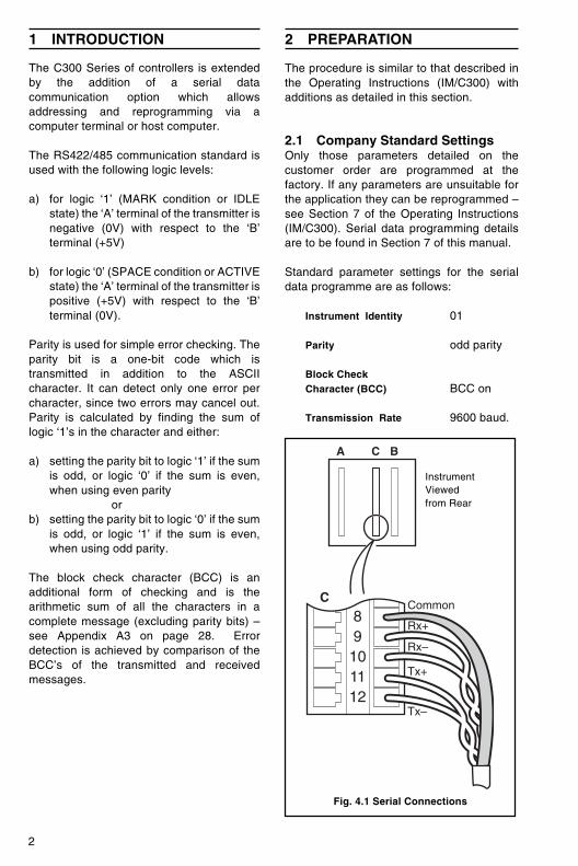
InstrumentViewedfrom Rear
Fig. 4.1 Serial Connections
89101112
Common
Rx+
Rx–
Tx+
Tx–
A BC
C
3
3 INSTALLATION
Observe the limitations outlined in theOperating Instructions (IM/C300). Themaximum serial data transmission linelength for both RS422 and RS485 systems is1200m.
3.1 Serial CommunicationAdaptors for Personal ComputersAn RS422/485 communications adaptorboard is required for serial links. It is stronglyrecommended that the card used hasgalvanic isolation to protect the computerfrom lightning damage and increaseimmunity from noise pick-up from cables.The following OPTO22 boards arerecommended for use with the C300 serialinstruments.
Part No. Computer TypeAC24 XT Bus IBM PC compatibleAC24 AT AT Bus IBM PC compatibleAC34 Microchannel IBM PC.
The following‘Jumper’ selections arerequired on OPTO22 boards (usuallysupplied as the default configuration):
RX & TX install line terminationjumperInstall pull-up and pull-down jumpers
CTS & RTS disable jumper installed.
Select board address and interrupts asdescribed in the OPTO22 manual.
4 ELECTRICAL CONNECTIONS
All connections, apart from those for serialdata communication, are made as shown inTable 4.2 in the Operating Instructions(IM/C300).
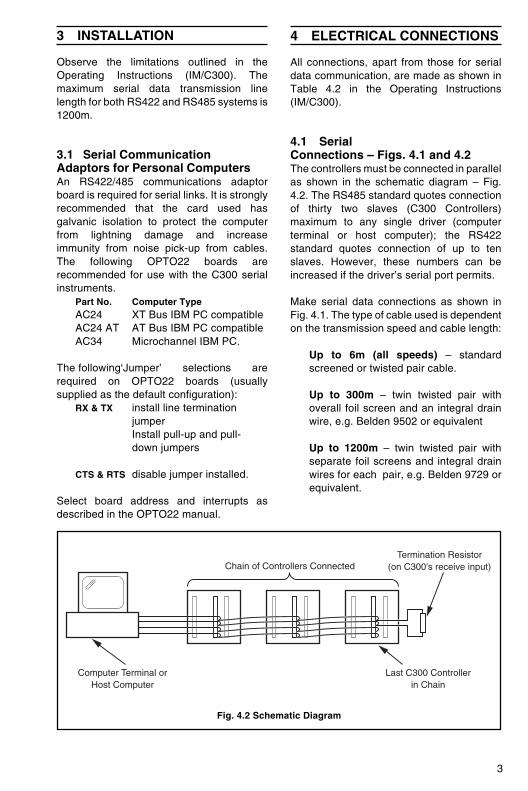
4.1 SerialConnections – Figs. 4.1 and 4.2The controllers must be connected in parallelas shown in the schematic diagram – Fig.4.2. The RS485 standard quotes connectionof thirty two slaves (C300 Controllers)maximum to any single driver (computerterminal or host computer); the RS422standard quotes connection of up to tenslaves. However, these numbers can beincreased if the driver’s serial port permits.
Make serial data connections as shown inFig. 4.1. The type of cable used is dependenton the transmission speed and cable length:
Up to 6m (all speeds) – standardscreened or twisted pair cable.
Up to 300m – twin twisted pair withoverall foil screen and an integral drainwire, e.g. Belden 9502 or equivalent
Up to 1200m – twin twisted pair withseparate foil screens and integral drainwires for each pair, e.g. Belden 9729 orequivalent.
Computer Terminal or Host Computer
Chain of Controllers Connected
Last C300 Controller in Chain
Termination Resistor (on C300's receive input)
Fig. 4.2 Schematic Diagram
4
6 PROTOCOL
The protocol used is based on ANSI-X3.28-1976-2.5-A4 and is used for master (hostcomputer) to slave (C300 Controller)systems. This is the recommended protocolfor use with supervisory systems such as ABBKent-Taylor PC30. The Protocol is:
Start transmission (STX) – Command –Identification … End transmission (ETX)– see Figs. 8.1 to 8.6 on pages 7 and 8.
Transmission of commands and processingof the subsequent replies must beincorporated into the host computerprogramme.
5 SETTING UP
For all aspects other than serial datatransmission the controller is set up asshown in the Operating Instructions (IM/C300). Unless otherwise requested, theinstrument is despatched with atransmission rate of 9600 baud andtransmission line termination resistorslinked-out. If the resistors are to be linked-in(see Fig. 4.2) carry out the following section.
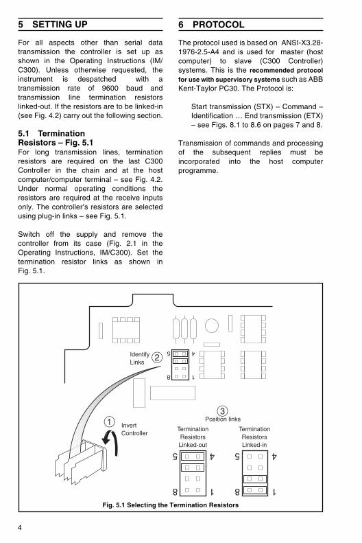
5.1 TerminationResistors – Fig. 5.1For long transmission lines, terminationresistors are required on the last C300Controller in the chain and at the hostcomputer/computer terminal – see Fig. 4.2.Under normal operating conditions theresistors are required at the receive inputsonly. The controller’s resistors are selectedusing plug-in links – see Fig. 5.1.
Switch off the supply and remove thecontroller from its case (Fig. 2.1 in theOperating Instructions, IM/C300). Set thetermination resistor links as shown inFig. 5.1.
Fig. 5.1 Selecting the Termination Resistors
2IdentifyLinks
18
45
18
45
18
45
3
TerminationResistorsLinked-out
InvertController
Position links
TerminationResistorsLinked-in
1
5
7.1 Serial Data Communication Page
7 PROGRAMMING
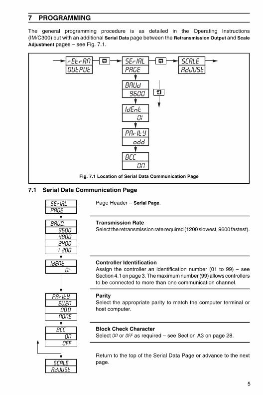
The general programming procedure is as detailed in the Operating Instructions(IM/C300) but with an additional Serial Data page between the Retransmission Output and ScaleAdjustment pages – see Fig. 7.1.
Page Header – Serial Page.
Transmission RateSelect the retransmission rate required (1200 slowest, 9600 fastest).
Controller IdentificationAssign the controller an identification number (01 to 99) – seeSection 4.1 on page 3. The maximum number (99) allows controllersto be connected to more than one communication channel.
ParitySelect the appropriate parity to match the computer terminal orhost computer.
Block Check CharacterSelect ON or OFF as required – see Section A3 on page 28.
Return to the top of the Serial Data Page or advance to the nextpage.
SErIALPAGE
�
BAUD9600480024001200�
IdENt01
�
PArItYEVENODDNONE�
BCCONOFF
�
SCALEAdJUSt
�
Fig. 7.1 Location of Serial Data Communication Page
SErIAL
BAUd9600
IdEnt01
PArItYodd
BCCON
PAGErEtrANOUtPUt
SCALEAdJUSt
6
8 COMMUNICATION
8.1 CommunicationBetween Master and SlavesThe commands from the master are codedas single characters as follows:
R – ‘Read’ (read parameters)
M – ‘Multiple Read’ (read a selectionof parameters)
W – ‘Write’ (write new parametervalues).
8.1.1 MnemonicsEach mnemonic for the C300 Controllerparameters comprises two characters – seeSection 8.6.
8.1.2 Relay LogicEquation (Q1, Q2)The alarm relay assignment is transmitted inthe format in which it is displayed.
✶ Note. The terminator is transmittedas a ‘#’, but appears on the display as ‘W’.
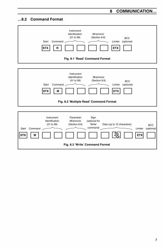
8.2 Command Format– Figs. 8.1 to 8.3The protocol is based on ANSI-X3.28-1976-2.5-A4. Entries are made directly from thehost computer using the command formatshown in Figs. 8.1 to 8.3.
8.2.1 Term Clarificationfor Command FormatStart – one ASCII control character (always‘STX’) signifying the start of transmission.
Command – one character, R, M or W – seeSection 8.1.
Instrument Identification – two charactersidentifying the C300 Controller, 01 to 99.
Parameter – two-character mnemonicselected from Section 8.6.
Sign – one character:‘+’ – parameter value is positive
(optional)‘–’ – parameter value is negative.
Data – usually up to six characters (includingdecimal point) used to write a new parametervalue. However, up to 12 characters may beused if Alarm Relay Assignment is beingcarried out, i.e. using mnemonics Q1 andQ2.
Limiter – one character (always ‘ETX’)signifying the end of data transmission.
Block Check Character (BCC) – one character,the arithmetic sum of the complete message(excluding parity bits), transmitted by thehost computer for error detection – seeAppendix A3 on page 28.
7
R
Command
InstrumentIdentification
(01 to 99)Mnemonic
(Section 8.6) BCC(optional)Limiter
STX
Start
ETX
8 COMMUNICATION…
…8.2 Command Format
Fig. 8.1 'Read' Command Format
M
Command
InstrumentIdentification
(01 to 99)Mnemonic
(Section 8.6) BCC(optional)Limiter
STX
Start
ETX
Fig. 8.2 'Multiple Read' Command Format
Command
InstrumentIdentification
(01 to 99)
ParameterMnemonic
(Section 8.6) BCC(optional)Limiter
W
Sign (optional for
'Write' command)
STX ETX
Start
Data (up to 12 characters)
W
Fig. 8.3 'Write' Command Format
8
InstrumentIdentification
(01 to 99)
ParameterMnemonic
(Section 8.6) BCC(optional)Reply
ACK
Sign Data (up to 12 characters)
…8 COMMUNICATION
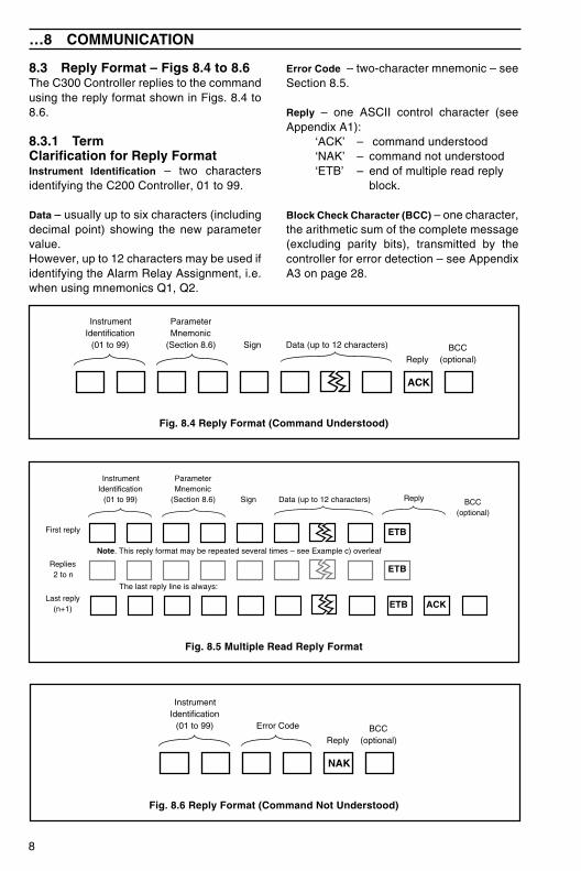
8.3 Reply Format – Figs 8.4 to 8.6The C300 Controller replies to the commandusing the reply format shown in Figs. 8.4 to8.6.
8.3.1 TermClarification for Reply FormatInstrument Identification – two charactersidentifying the C200 Controller, 01 to 99.
Data – usually up to six characters (includingdecimal point) showing the new parametervalue.However, up to 12 characters may be used ifidentifying the Alarm Relay Assignment, i.e.when using mnemonics Q1, Q2.
Error Code – two-character mnemonic – seeSection 8.5.
Reply – one ASCII control character (seeAppendix A1):
‘ACK’ – command understood‘NAK’ – command not understood‘ETB’ – end of multiple read reply
block.
Block Check Character (BCC) – one character,the arithmetic sum of the complete message(excluding parity bits), transmitted by thecontroller for error detection – see AppendixA3 on page 28.
Fig. 8.4 Reply Format (Command Understood)
InstrumentIdentification
(01 to 99)
ParameterMnemonic
(Section 8.6) BCC(optional)
ReplySign Data (up to 12 characters)
ACK
ETB
ETB
Note. This reply format may be repeated several times – see Example c) overleaf
The last reply line is always:
First reply
Replies2 to n
Last reply(n+1) ETB
Fig. 8.5 Multiple Read Reply Format
InstrumentIdentification
(01 to 99) Error Code BCC(optional)Reply
NAK
Fig. 8.6 Reply Format (Command Not Understood)
9
8 COMMUNICATION…
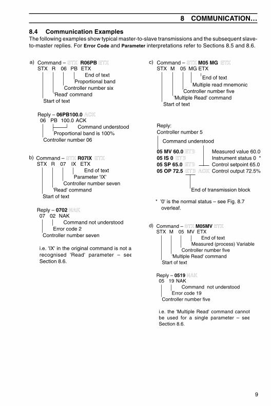
8.4 Communication ExamplesThe following examples show typical master-to-slave transmissions and the subsequent slave-to-master replies. For Error Code and Parameter interpretations refer to Sections 8.5 and 8.6.
MSTX 05
End of text
c) Command – STX M05 MG EETX
Command understood
Controller number 5Reply:
MG ETX
Controller number five'Multiple Read' command
Start of text
05 MV 60.0 ACK05 IS 005 SP 65.0 ACK05 OP 72.5 ACKACK
Measured value 60.0Instrument status 0 *Control setpoint 65.0Control output 72.5%
ETBETB
ETBETB ACK
Multiple read mnemonic
End of transmission block
* '0' is the normal status – see Fig. 8.7 overleaf.
MSTX 05End of text
d) Command – STX M05MV ETX
05 19Command not understood
Error code 19
Reply – 0519 NNAK
MV ETX
Measured (process) VariableController number five
'Multiple Read' commandStart of text
NAK
Controller number five
i.e. the 'Multiple Read' command cannotbe used for a single parameter – seeSection 8.6.
06
RSTX 06End of text
a)
PB 100.0Command understood
Proportional band is 100%
PB ETX
Proportional bandController number six
'Read' commandStart of text
ACK
Controller number 06
Command – STX R06PB EETX
Reply – 06PB100.0 ACK
07
RSTX 07End of text
b)
02 NAKCommand not understood
Error code 2
IX ETX
Parameter 'IX'Controller number seven
'Read' commandStart of text
Controller number seven
i.e. 'IX' in the original command is not a recognised 'Read' parameter – seeSection 8.6.
Command – STX R07IX EETX
Reply – 0702 NAK
10
…8 COMMUNICATION
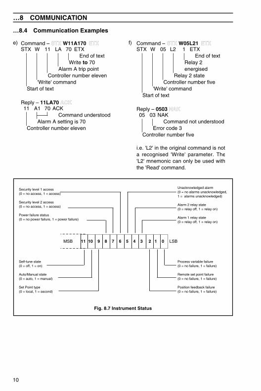
…8.4 Communication Examples
11
WSTX 11End of text
e) Command – STX W11A170 EETX
A1 70Command understood
Alarm A setting is 70
Reply – 11LA70 ACK
LA 70 ETX
Write to 70Alarm A trip point
Controller number eleven'Write' command
Start of text
ACK
Controller number eleven
05
WSTX 05End of text
f) Command – STX W05L21 EETX
03Command not understood
Error code 3
Reply – 0503 NNAK
L2 1 ETX
Relay 2 energised
Relay 2 stateController number five
'Write' commandStart of text
NAK
Controller number five
i.e. 'L2' in the original command is not a recognised 'Write' parameter. The'L2' mnemonic can only be used withthe 'Read' command.
Self-tune state(0 = off, 1 = on)
Auto/Manual state(0 = auto, 1 = manual)
Set Point type(0 = local, 1 = second)
Security level 1 access(0 = no access, 1 = access)
Security level 2 access(0 = no access, 1 = access)
Power failure status (0 = no power failure, 1 = power failure)
Process variable failure(0 = no failure, 1 = failure)
Remote set point failure(0 = no failure, 1 = failure)
Position feedback failure(0 = no failure, 1 = failure)
11 10 9 8 7 6 5 4 3 2 1 0MSB LSB
Unacknowledged alarm(0 = no alarms unacknowledged, 1 = alarms unacknowledged)
Alarm 2 relay state (0 = relay off, 1 = relay on)
Alarm 1 relay state(0 = relay off, 1 = relay on)
Fig. 8.7 Instrument Status
11
8 COMMUNICATION…
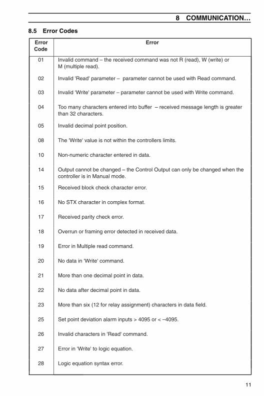
8.5 Error Codes
ErrorCode
Error
01 Invalid command – the received command was not R (read), W (write) orM (multiple read).
02 Invalid 'Read' parameter – parameter cannot be used with Read command.
03 Invalid 'Write' parameter – parameter cannot be used with Write command.
04 Too many characters entered into buffer – received message length is greaterthan 32 characters.
05 Invalid decimal point position.
08 The 'Write' value is not within the controllers limits.
10 Non-numeric character entered in data.
14 Output cannot be changed – the Control Output can only be changed when thecontroller is in Manual mode.
15 Received block check character error.
16 No STX character in complex format.
17 Received parity check error.
18 Overrun or framing error detected in received data.
19 Error in Multiple read command.
20 No data in 'Write' command.
21 More than one decimal point in data.
22 No data after decimal point in data.
23 More than six (12 for relay assignment) characters in data field.
25 Set point deviation alarm inputs > 4095 or < –4095.
26 Invalid characters in 'Read' command.
27 Error in 'Write' to logic equation.
28 Logic equation syntax error.
12
…8 COMMUNICATION
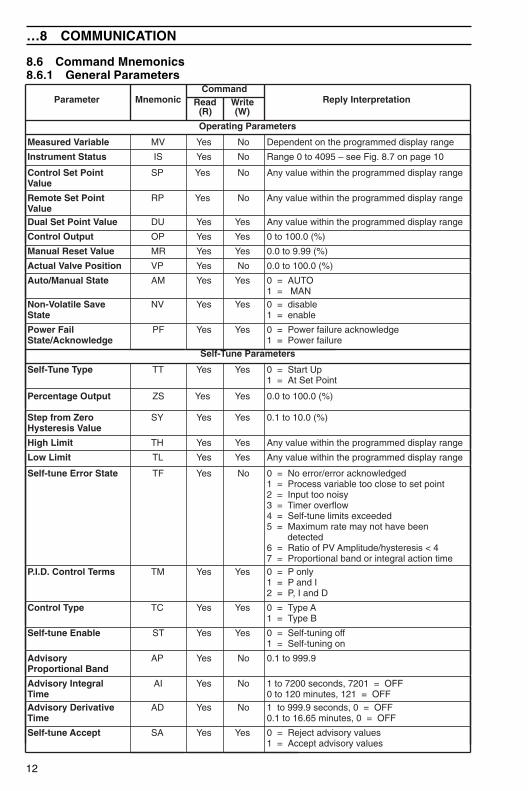
8.6 Command Mnemonics8.6.1 General Parameters
Parameter MnemonicCommand
Reply InterpretationRead(R)
Write(W)
Operating Parameters
Measured Variable MV Yes No Dependent on the programmed display range
Instrument Status IS Yes No Range 0 to 4095 – see Fig. 8.7 on page 10
Control Set PointValue
SP Yes No Any value within the programmed display range
Remote Set PointValue
RP Yes No Any value within the programmed display range
Dual Set Point Value DU Yes Yes Any value within the programmed display range
Control Output OP Yes Yes 0 to 100.0 (%)
Manual Reset Value MR Yes Yes 0.0 to 9.99 (%)
Actual Valve Position VP Yes No 0.0 to 100.0 (%)
Auto/Manual State AM Yes Yes 0 = AUTO1 = MAN
Non-Volatile SaveState
NV Yes Yes 0 = disable1 = enable
Power FailState/Acknowledge
PF Yes Yes 0 = Power failure acknowledge1 = Power failure
Self-Tune Parameters
Self-Tune Type TT Yes Yes 0 = Start Up1 = At Set Point
Percentage Output ZS Yes Yes 0.0 to 100.0 (%)
Step from ZeroHysteresis Value
SY Yes Yes 0.1 to 10.0 (%)
High Limit TH Yes Yes Any value within the programmed display range
Low Limit TL Yes Yes Any value within the programmed display range
Self-tune Error State TF Yes No 0 = No error/error acknowledged1 = Process variable too close to set point2 = Input too noisy3 = Timer overflow4 = Self-tune limits exceeded5 = Maximum rate may not have been
detected6 = Ratio of PV Amplitude/hysteresis < 47 = Proportional band or integral action time
P.I.D. Control Terms TM Yes Yes 0 = P only1 = P and I2 = P, I and D
Control Type TC Yes Yes 0 = Type A1 = Type B
Self-tune Enable ST Yes Yes 0 = Self-tuning off1 = Self-tuning on
AdvisoryProportional Band
AP Yes No 0.1 to 999.9
Advisory IntegralTime
AI Yes No 1 to 7200 seconds, 7201 = OFF0 to 120 minutes, 121 = OFF
Advisory DerivativeTime
AD Yes No 1 to 999.9 seconds, 0 = OFF0.1 to 16.65 minutes, 0 = OFF
Self-tune Accept SA Yes Yes 0 = Reject advisory values1 = Accept advisory values
13
8 COMMUNICATION…
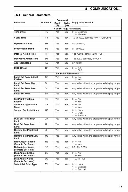
8.6.1 General Parameters…
Parameter MnemonicCommand
Reply InterpretationRead(R)
Write(W)
Control Page ParametersTime Units TU Yes Yes 0 = Seconds
1 = MinutesCycle Time CT Yes Yes 1.0 to 300.0 seconds (0.9 = ON/OFF)
Hysteresis Value HY Yes Yes 0.0 to 5.0(%)
Proportional Band PB Yes Yes 0.1 to 999.9
Integral Action Time IT Yes Yes 1 to 7200 seconds, 7201 = OFF
Derivative Action Time DT Yes Yes 1 to 999.9 seconds, 0 = OFF
Approach Band AB Yes Yes 0.1 to 3.0
P.I.D. Offset OF Yes Yes 0 = 0.01 = 50.0
Set Point Parameters
Local Set Point AdjustEnable
SE Yes Yes 0 = No1 = Yes
Local Set Point HighLimit
SH Yes Yes Any value within the programmed display range
Local Set Point LowLimit
SL Yes Yes Any value within the programmed display range
Local Set Point LP Yes Yes Any value within the programmed display range
Set Point TrackingEnable
TE Yes Yes 0 = No1 = Yes
Set Point Type SelectState
TS Yes Yes 0 = No1 = Yes
Second Set Point State UE Yes Yes 0 = None1 = Dual2 = Remote
Dual Set Point HighLimit
UH Yes Yes Any value within the programmed display range
Dual Set Point LowLimit
UL Yes Yes Any value within the programmed display range
Remote Set Point HighLimit
MH Yes Yes Any value within the programmed display range
Remote Set Point LowLimit
ML Yes Yes Any value within the programmed display range
Ratio Adjust Enable(Remote Set Point)
RE Yes Yes 0 = No1 = Yes
Ratio Adjust Value(Remote Set Point)
RO Yes Yes 0.010 to 9.999
Bias Adjust Enable(Remote Set Point)
BE Yes Yes 0 = No1 = Yes
Bias Adjust Value(Remote Set point)
BO Yes Yes –100 to +100
Select Set Point Type TY Yes Yes 0 = Local1 = Balance2 = Second
14
…8 COMMUNICATION
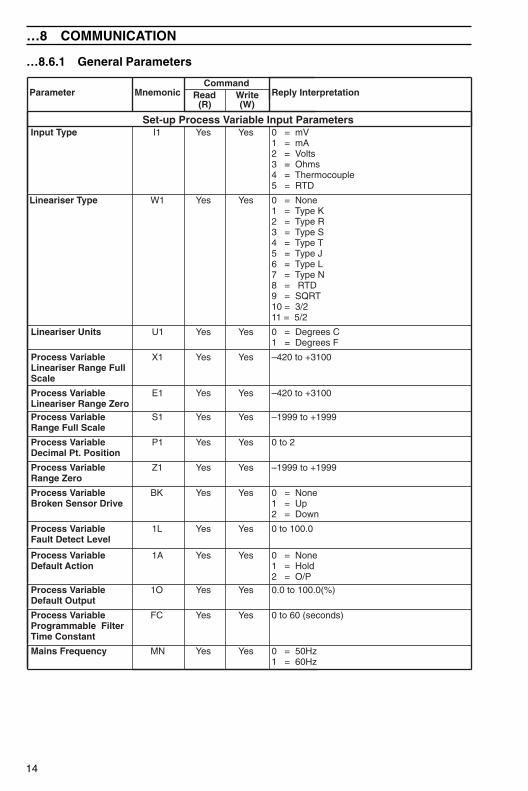
…8.6.1 General Parameters
Parameter MnemonicCommand
Reply InterpretationRead(R)
Write(W)
Set-up Process Variable Input Parameters Input Type I1 Yes Yes 0 = mV
1 = mA2 = Volts3 = Ohms4 = Thermocouple5 = RTD
Lineariser Type W1 Yes Yes 0 = None1 = Type K2 = Type R3 = Type S4 = Type T5 = Type J6 = Type L7 = Type N8 = RTD9 = SQRT10 = 3/211 = 5/2
Lineariser Units U1 Yes Yes 0 = Degrees C1 = Degrees F
Process VariableLineariser Range FullScale
X1 Yes Yes –420 to +3100
Process VariableLineariser Range Zero
E1 Yes Yes –420 to +3100
Process VariableRange Full Scale
S1 Yes Yes –1999 to +1999
Process VariableDecimal Pt. Position
P1 Yes Yes 0 to 2
Process VariableRange Zero
Z1 Yes Yes –1999 to +1999
Process VariableBroken Sensor Drive
BK Yes Yes 0 = None1 = Up2 = Down
Process VariableFault Detect Level
1L Yes Yes 0 to 100.0
Process VariableDefault Action
1A Yes Yes 0 = None1 = Hold2 = O/P
Process VariableDefault Output
1O Yes Yes 0.0 to 100.0(%)
Process VariableProgrammable FilterTime Constant
FC Yes Yes 0 to 60 (seconds)
Mains Frequency MN Yes Yes 0 = 50Hz1 = 60Hz
15
8 COMMUNICATION…
8.6.1 General Parameters…
Parameter MnemonicCommand
Reply InterpretationRead(R)
Write(W)
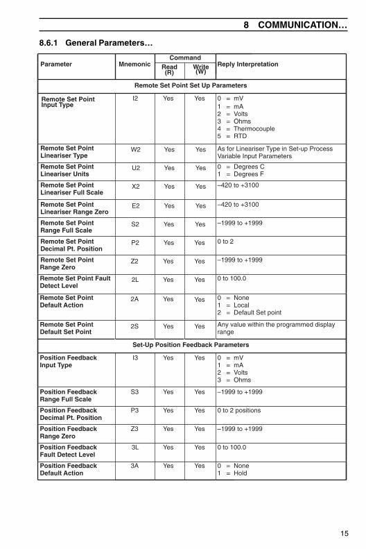
Remote Set Point Set Up Parameters
Remote Set PointInput Type
I2 Yes Yes 0 = mV1 = mA2 = Volts3 = Ohms4 = Thermocouple5 = RTD
Remote Set PointLineariser Type
W2 Yes Yes As for Lineariser Type in Set-up ProcessVariable Input Parameters
Remote Set PointLineariser Units
U2 Yes Yes 0 = Degrees C1 = Degrees F
Remote Set PointLineariser Full Scale
X2 Yes Yes –420 to +3100
Remote Set PointLineariser Range Zero
E2 Yes Yes –420 to +3100
Remote Set PointRange Full Scale
S2 Yes Yes –1999 to +1999
Remote Set PointDecimal Pt. Position
P2 Yes Yes 0 to 2
Remote Set PointRange Zero
Z2 Yes Yes –1999 to +1999
Remote Set Point FaultDetect Level
2L Yes Yes 0 to 100.0
Remote Set PointDefault Action
2A Yes Yes 0 = None1 = Local2 = Default Set point
Remote Set PointDefault Set Point
2S Yes Yes Any value within the programmed displayrange
Set-Up Position Feedback Parameters
Position FeedbackInput Type
I3 Yes Yes 0 = mV1 = mA2 = Volts3 = Ohms
Position FeedbackRange Full Scale
S3 Yes Yes –1999 to +1999
Position FeedbackDecimal Pt. Position
P3 Yes Yes 0 to 2 positions
Position FeedbackRange Zero
Z3 Yes Yes –1999 to +1999
Position FeedbackFault Detect Level
3L Yes Yes 0 to 100.0
Position FeedbackDefault Action
3A Yes Yes 0 = None1 = Hold
16
…8 COMMUNICATION
…8.6.1 General Parameters
Parameter MnemonicCommand
Reply InterpretationRead(R)
Write(W)
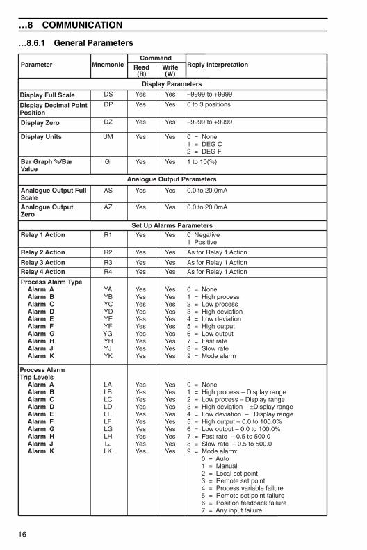
Display Parameters
Display Full Scale DS Yes Yes –9999 to +9999
Display Decimal PointPosition
DP Yes Yes 0 to 3 positions
Display Zero DZ Yes Yes –9999 to +9999
Display Units UM Yes Yes 0 = None1 = DEG C2 = DEG F
Bar Graph %/BarValue
GI Yes Yes 1 to 10(%)
Analogue Output Parameters
Analogue Output FullScale
AS Yes Yes 0.0 to 20.0mA
Analogue OutputZero
AZ Yes Yes 0.0 to 20.0mA
Set Up Alarms ParametersRelay 1 Action R1 Yes Yes 0 Negative
1 Positive
Relay 2 Action R2 Yes Yes As for Relay 1 Action
Relay 3 Action R3 Yes Yes As for Relay 1 ActionRelay 4 Action R4 Yes Yes As for Relay 1 Action
Process Alarm Type Alarm A Alarm B Alarm C Alarm D Alarm E Alarm F Alarm G Alarm H Alarm J Alarm K
YAYBYCYDYEYFYGYHYJYK
YesYesYesYesYesYesYesYesYesYes
YesYesYesYesYesYesYesYesYesYes
0 = None1 = High process2 = Low process3 = High deviation4 = Low deviation5 = High output6 = Low output7 = Fast rate8 = Slow rate9 = Mode alarm
Process AlarmTrip Levels Alarm A Alarm B Alarm C Alarm D Alarm E Alarm F Alarm G Alarm H Alarm J Alarm K
LALBLCLDLELFLGLHLJLK
YesYesYesYesYesYesYesYesYesYes
YesYesYesYesYesYesYesYesYesYes
0 = None1 = High process – Display range2 = Low process – Display range3 = High deviation – ±Display range4 = Low deviation – ±Display range5 = High output – 0.0 to 100.0%6 = Low output – 0.0 to 100.0%7 = Fast rate – 0.5 to 500.08 = Slow rate – 0.5 to 500.09 = Mode alarm: 0 = Auto 1 = Manual 2 = Local set point 3 = Remote set point 4 = Process variable failure 5 = Remote set point failure 6 = Position feedback failure 7 = Any input failure
17
8 COMMUNICATION…
8.6.1 General Parameters…
Parameter MnemonicCommand
Reply InterpretationRead(R)
Write(W)
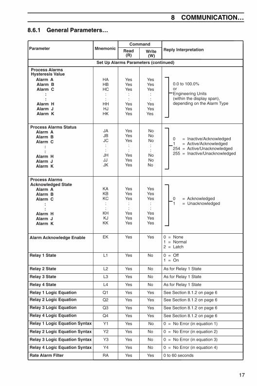
Set Up Alarms Parameters (continued)
Process AlarmsHysteresis Value Alarm A Alarm B Alarm C
::
Alarm H Alarm J Alarm K
HAHBHC
::
HHHJHK
YesYesYes
::
YesYesYes
YesYesYes
::
YesYesYes
0.0 to 100.0% orEngineering Units(within the display span),depending on the Alarm Type
Process Alarms Status Alarm A Alarm B Alarm C
::
Alarm H Alarm J Alarm K
JAJBJC::
JHJJJK
YesYesYes
::
YesYesYes
NoNoNo::
NoNoNo
0 = Inactive/Acknowledged1 = Active/Acknowledged254 = Active/Unacknowledged255 = Inactive/Unacknowledged
Process AlarmsAcknowledged State Alarm A Alarm B Alarm C
::
Alarm H Alarm J Alarm K
KAKBKC
::
KHKJKK
YesYesYes
::
YesYesYes
YesYesYes
::
YesYesYes
0 = Acknowledged1 = Unacknowledged
Alarm Acknowledge Enable EK Yes Yes 0 = None1 = Normal2 = Latch
Relay 1 State L1 Yes No 0 = Off1 = On
Relay 2 State L2 Yes No As for Relay 1 State
Relay 3 State L3 Yes No As for Relay 1 State
Relay 4 State L4 Yes No As for Relay 1 State
Relay 1 Logic Equation Q1 Yes Yes See Section 8.1.2 on page 6
Relay 2 Logic Equation Q2 Yes Yes See Section 8.1.2 on page 6
Relay 3 Logic Equation Q3 Yes Yes See Section 8.1.2 on page 6
Relay 4 Logic Equation Q4 Yes Yes See Section 8.1.2 on page 6
Relay 1 Logic Equation Syntax Y1 Yes No 0 = No Error (in equation 1)
Relay 2 Logic Equation Syntax Y2 Yes No 0 = No Error (in equation 2)
Relay 3 Logic Equation Syntax Y3 Yes No 0 = No Error (in equation 3)
Relay 4 Logic Equation Syntax Y4 Yes No 0 = No Error (in equation 4)
Rate Alarm Filter RA Yes Yes 0 to 60 seconds
18
…8 COMMUNICATION
…8.6.1 General Parameters
Parameter MnemonicCommand
Reply InterpretationRead(R)
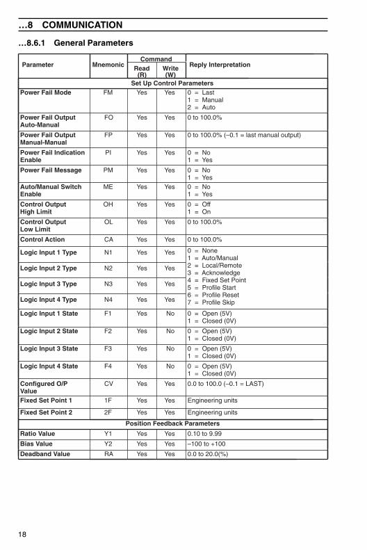
Write(W)
Set Up Control ParametersPower Fail Mode FM Yes Yes 0 = Last
1 = Manual2 = Auto
Power Fail OutputAuto-Manual
FO Yes Yes 0 to 100.0%
Power Fail OutputManual-Manual
FP Yes Yes 0 to 100.0% (–0.1 = last manual output)
Power Fail IndicationEnable
PI Yes Yes 0 = No1 = Yes
Power Fail Message PM Yes Yes 0 = No1 = Yes
Auto/Manual SwitchEnable
ME Yes Yes 0 = No1 = Yes
Control OutputHigh Limit
OH Yes Yes 0 = Off1 = On
Control OutputLow Limit
OL Yes Yes 0 to 100.0%
Control Action CA Yes Yes 0 to 100.0%
Logic Input 1 Type N1 Yes Yes 0 = None1 = Auto/Manual2 = Local/Remote3 = Acknowledge4 = Fixed Set Point5 = Profile Start6 = Profile Reset7 = Profile Skip
Logic Input 2 Type N2 Yes Yes
Logic Input 3 Type N3 Yes Yes
Logic Input 4 Type N4 Yes Yes
Logic Input 1 State F1 Yes No 0 = Open (5V)1 = Closed (0V)
Logic Input 2 State F2 Yes No 0 = Open (5V)1 = Closed (0V)
Logic Input 3 State F3 Yes No 0 = Open (5V)1 = Closed (0V)
Logic Input 4 State F4 Yes No 0 = Open (5V)1 = Closed (0V)
Configured O/PValue
CV Yes Yes 0.0 to 100.0 (–0.1 = LAST)
Fixed Set Point 1 1F Yes Yes Engineering units
Fixed Set Point 2 2F Yes Yes Engineering units
Position Feedback Parameters
Ratio Value Y1 Yes Yes 0.10 to 9.99
Bias Value Y2 Yes Yes –100 to +100
Deadband Value RA Yes Yes 0.0 to 20.0(%)
19
8 COMMUNICATION…
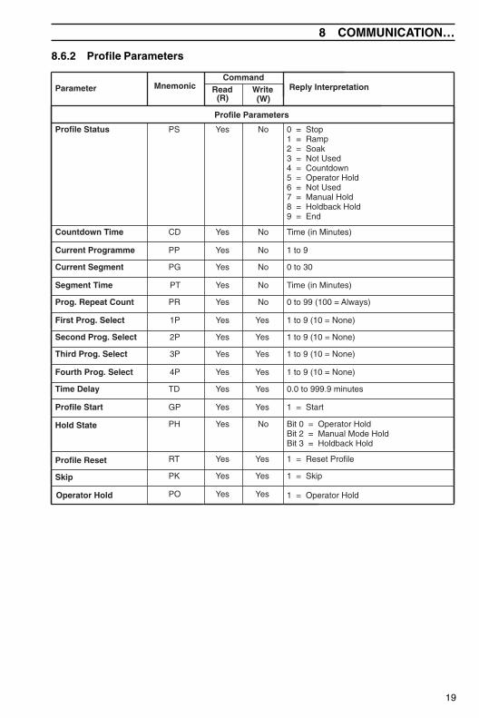
8.6.2 Profile Parameters
Parameter MnemonicCommand
Reply InterpretationRead(R)
Write(W)
Profile Parameters
Profile Status PS Yes No 0 = Stop1 = Ramp2 = Soak3 = Not Used4 = Countdown5 = Operator Hold6 = Not Used7 = Manual Hold8 = Holdback Hold9 = End
Countdown Time CD Yes No Time (in Minutes)
Current Programme PP Yes No 1 to 9
Current Segment PG Yes No 0 to 30
Segment Time PT Yes No Time (in Minutes)
Prog. Repeat Count PR Yes No 0 to 99 (100 = Always)
First Prog. Select 1P Yes Yes 1 to 9 (10 = None)
Second Prog. Select 2P Yes Yes 1 to 9 (10 = None)
Third Prog. Select 3P Yes Yes 1 to 9 (10 = None)
Fourth Prog. Select 4P Yes Yes 1 to 9 (10 = None)
Time Delay TD Yes Yes 0.0 to 999.9 minutes
Profile Start GP Yes Yes 1 = Start
Hold State PH Yes No Bit 0 = Operator HoldBit 2 = Manual Mode HoldBit 3 = Holdback Hold
Profile Reset RT Yes Yes 1 = Reset Profile
Skip PK Yes Yes 1 = Skip
Operator Hold PO Yes Yes 1 = Operator Hold
20
…8 COMMUNICATION
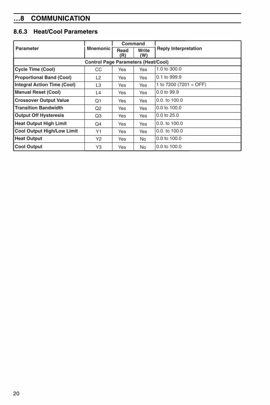
8.6.3 Heat/Cool Parameters
Parameter MnemonicCommand
Reply InterpretationRead(R)
Write(W)
Control Page Parameters (Heat/Cool)
Cycle Time (Cool) CC Yes Yes 1.0 to 300.0
Proportional Band (Cool) L2 Yes Yes 0.1 to 999.9
Integral Action Time (Cool) L3 Yes Yes 1 to 7200 (7201 = OFF)
Manual Reset (Cool) L4 Yes Yes 0.0 to 99.9
Crossover Output Value Q1 Yes Yes 0.0. to 100.0
Transition Bandwidth Q2 Yes Yes 0.0 to 100.0
Output Off Hysteresis Q3 Yes Yes 0.0 to 25.0
Heat Output High Limit Q4 Yes Yes 0.0. to 100.0
Cool Output High/Low Limit Y1 Yes Yes 0.0. to 100.0
Heat Output Y2 Yes No 0.0 to 100.0
Cool Output Y3 Yes No 0.0 to 100.0
21
8 COMMUNICATION…
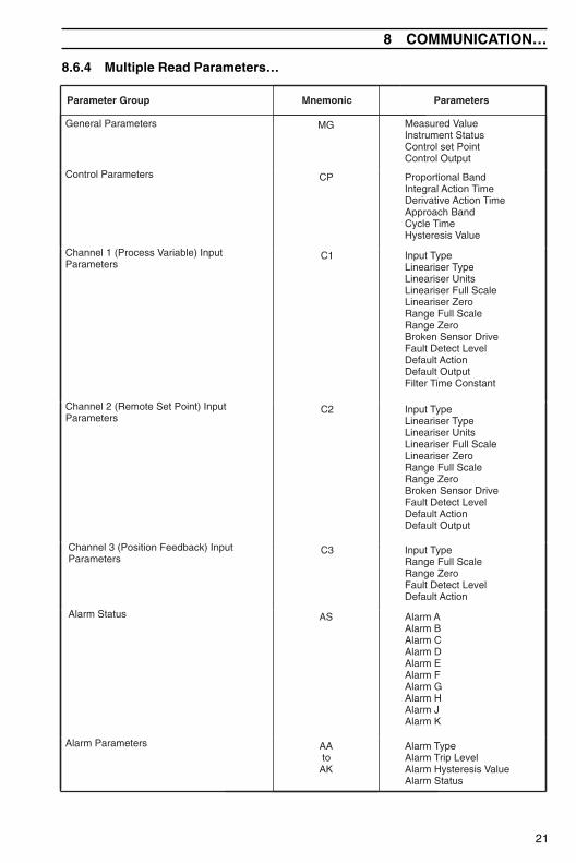
8.6.4 Multiple Read Parameters…
Parameter Group Mnemonic Parameters
General Parameters MG Measured ValueInstrument StatusControl set PointControl Output
Control Parameters CP Proportional BandIntegral Action TimeDerivative Action TimeApproach BandCycle TimeHysteresis Value
Channel 1 (Process Variable) InputParameters
C1 Input TypeLineariser TypeLineariser UnitsLineariser Full ScaleLineariser ZeroRange Full ScaleRange ZeroBroken Sensor DriveFault Detect LevelDefault ActionDefault OutputFilter Time Constant
Channel 2 (Remote Set Point) InputParameters
C2 Input TypeLineariser TypeLineariser UnitsLineariser Full ScaleLineariser ZeroRange Full ScaleRange ZeroBroken Sensor DriveFault Detect LevelDefault ActionDefault Output
Channel 3 (Position Feedback) InputParameters
C3 Input TypeRange Full ScaleRange ZeroFault Detect LevelDefault Action
Alarm Status AS Alarm AAlarm BAlarm CAlarm DAlarm EAlarm FAlarm GAlarm HAlarm JAlarm K
Alarm Parameters AAto
AK
Alarm TypeAlarm Trip LevelAlarm Hysteresis ValueAlarm Status
22
…8 COMMUNICATION
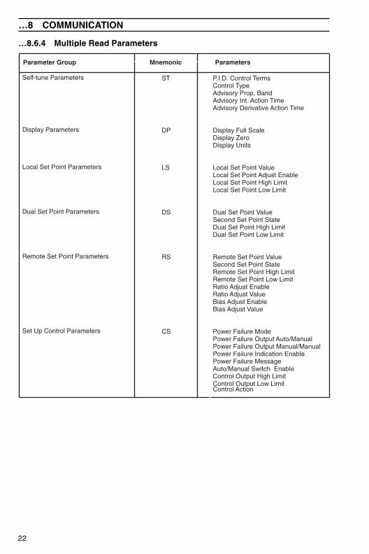
…8.6.4 Multiple Read Parameters
Parameter Group Mnemonic Parameters
Self-tune Parameters
Display Parameters
Local Set Point Parameters
Dual Set Point Parameters
Remote Set Point Parameters
Set Up Control Parameters
ST
DP
LS
DS
RS
CS
P.I.D. Control TermsControl TypeAdvisory Prop. BandAdvisory Int. Action TimeAdvisory Derivative Action Time
Display Full ScaleDisplay ZeroDisplay Units
Local Set Point ValueLocal Set Point Adjust EnableLocal Set Point High LimitLocal Set Point Low Limit
Dual Set Point ValueSecond Set Point StateDual Set Point High LimitDual Set Point Low Limit
Remote Set Point ValueSecond Set Point StateRemote Set Point High LimitRemote Set Point Low LimitRatio Adjust EnableRatio Adjust ValueBias Adjust EnableBias Adjust Value
Power Failure ModePower Failure Output Auto/ManualPower Failure Output Manual/ManualPower Failure Indication EnablePower Failure MessageAuto/Manual Switch EnableControl Output High LimitControl Output Low LimitControl Action
23
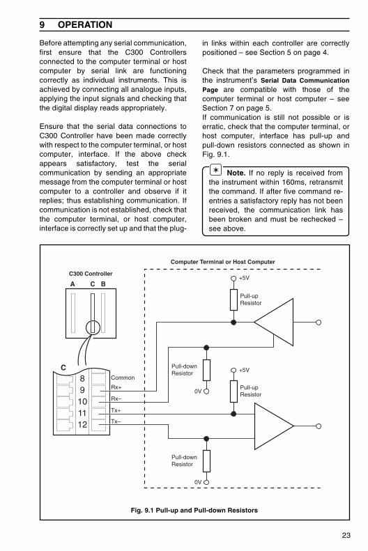
9 OPERATION
Before attempting any serial communication,first ensure that the C300 Controllersconnected to the computer terminal or hostcomputer by serial link are functioningcorrectly as individual instruments. This isachieved by connecting all analogue inputs,applying the input signals and checking thatthe digital display reads appropriately.
Ensure that the serial data connections toC300 Controller have been made correctlywith respect to the computer terminal, or hostcomputer, interface. If the above checkappears satisfactory, test the serialcommunication by sending an appropriatemessage from the computer terminal or hostcomputer to a controller and observe if itreplies; thus establishing communication. Ifcommunication is not established, check thatthe computer terminal, or host computer,interface is correctly set up and that the plug-
in links within each controller are correctlypositioned – see Section 5 on page 4.
Check that the parameters programmed inthe instrument’s Serial Data CommunicationPage are compatible with those of thecomputer terminal or host computer – seeSection 7 on page 5.If communication is still not possible or iserratic, check that the computer terminal, orhost computer, interface has pull-up andpull-down resistors connected as shown inFig. 9.1.
✶ Note. If no reply is received fromthe instrument within 160ms, retransmitthe command. If after five command re-entries a satisfactory reply has not beenreceived, the communication link hasbeen broken and must be rechecked –see above.
89101112
Common
Rx+
Rx–
Tx+
Tx–
A BC
C
+5V
+5V
0V
0V
Pull-upResistor
Pull-upResistor
Pull-downResistor
Pull-downResistor
Computer Terminal or Host Computer
C300 Controller
Fig. 9.1 Pull-up and Pull-down Resistors

24
10 SPECIFICATION
As detailed in the Operating Instructions (IM/C300), with the following additions:
EIA Communication Standards RS422 and RS485
Parity NoneOddEven
Block check character Programmable on or off
Transmission line length 1200m max.
Transmission speeds 1200 baud2400 baud4800 baud9600 baud
Programmable
25
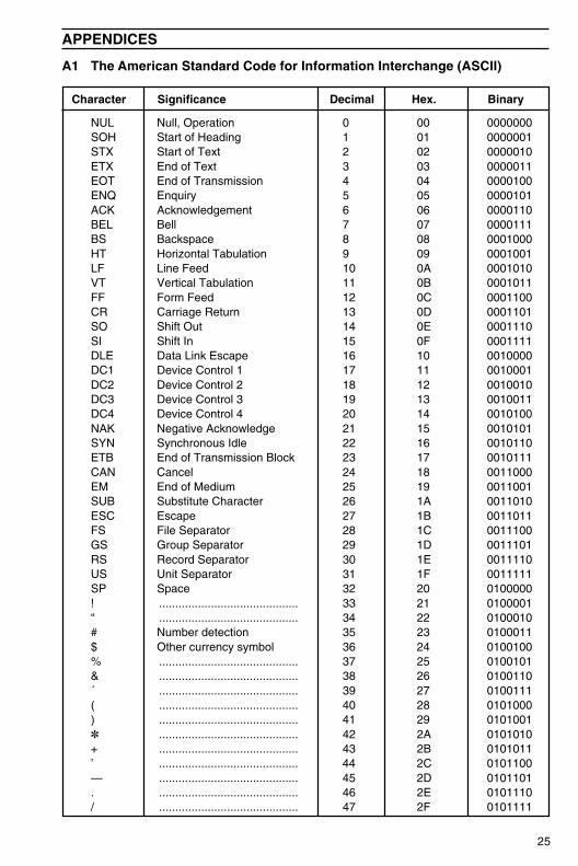
A1 The American Standard Code for Information Interchange (ASCII)
Character Significance Decimal Hex. Binary
NUL Null, Operation 0 00 0000000SOH Start of Heading 1 01 0000001STX Start of Text 2 02 0000010ETX End of Text 3 03 0000011EOT End of Transmission 4 04 0000100ENQ Enquiry 5 05 0000101ACK Acknowledgement 6 06 0000110BEL Bell 7 07 0000111BS Backspace 8 08 0001000HT Horizontal Tabulation 9 09 0001001LF Line Feed 10 0A 0001010VT Vertical Tabulation 11 0B 0001011FF Form Feed 12 0C 0001100CR Carriage Return 13 0D 0001101SO Shift Out 14 0E 0001110SI Shift In 15 0F 0001111DLE Data Link Escape 16 10 0010000DC1 Device Control 1 17 11 0010001DC2 Device Control 2 18 12 0010010DC3 Device Control 3 19 13 0010011DC4 Device Control 4 20 14 0010100NAK Negative Acknowledge 21 15 0010101SYN Synchronous Idle 22 16 0010110ETB End of Transmission Block 23 17 0010111CAN Cancel 24 18 0011000EM End of Medium 25 19 0011001SUB Substitute Character 26 1A 0011010ESC Escape 27 1B 0011011FS File Separator 28 1C 0011100GS Group Separator 29 1D 0011101RS Record Separator 30 1E 0011110US Unit Separator 31 1F 0011111SP Space 32 20 0100000! ........................................... 33 21 0100001“ ........................................... 34 22 0100010# Number detection 35 23 0100011$ Other currency symbol 36 24 0100100% ........................................... 37 25 0100101& ........................................... 38 26 0100110´ ........................................... 39 27 0100111( ........................................... 40 28 0101000) ........................................... 41 29 0101001✽ ........................................... 42 2A 0101010+ ........................................... 43 2B 0101011’ ........................................... 44 2C 0101100— ........................................... 45 2D 0101101. ........................................... 46 2E 0101110/ ........................................... 47 2F 0101111
APPENDICES
26
…APPENDICES
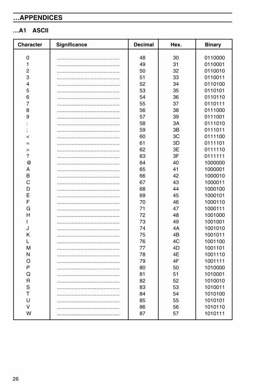
…A1 ASCII
Character Significance Decimal Hex. Binary
0 ........................................... 48 30 01100001 ........................................... 49 31 01100012 ........................................... 50 32 01100103 ........................................... 51 33 01100114 ........................................... 52 34 01101005 ........................................... 53 35 01101016 ........................................... 54 36 01101107 ........................................... 55 37 01101118 ........................................... 56 38 01110009 ........................................... 57 39 0111001: ........................................... 58 3A 0111010; ........................................... 59 3B 0111011< ........................................... 60 3C 0111100= ........................................... 61 3D 0111101> ........................................... 62 3E 0111110? ........................................... 63 3F 0111111@ ........................................... 64 40 1000000A ........................................... 65 41 1000001B ........................................... 66 42 1000010C ........................................... 67 43 1000011D ........................................... 68 44 1000100E ........................................... 69 45 1000101F ........................................... 70 46 1000110G ........................................... 71 47 1000111H ........................................... 72 48 1001000I ........................................... 73 49 1001001J ........................................... 74 4A 1001010K ........................................... 75 4B 1001011L ........................................... 76 4C 1001100M ........................................... 77 4D 1001101N ........................................... 78 4E 1001110O ........................................... 79 4F 1001111P ........................................... 80 50 1010000Q ........................................... 81 51 1010001R ........................................... 82 52 1010010S ........................................... 83 53 1010011T ........................................... 84 54 1010100U ........................................... 85 55 1010101V ........................................... 86 56 1010110W ........................................... 87 57 1010111
27
APPENDICES…
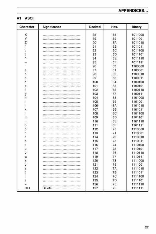
A1 ASCII
Character Significance Decimal Hex. Binary
X ........................................... 88 58 1011000Y ........................................... 89 59 1011001Z ........................................... 90 5A 1011010[ ........................................... 91 5B 1011011\ ........................................... 92 5C 1011100] ........................................... 93 5D 1011101^ ........................................... 94 5E 1011110-- ........................................... 95 5F 1011111` ........................................... 96 60 1100000a ........................................... 97 61 1100001b ........................................... 98 62 1100010c ........................................... 99 63 1100011d ........................................... 100 64 1100100e ........................................... 101 65 1100101f ........................................... 102 66 1100110g ........................................... 103 67 1100111h ........................................... 104 68 1101000i ........................................... 105 69 1101001j ........................................... 106 6A 1101010k ........................................... 107 6B 1101011l ........................................... 108 6C 1101100m ........................................... 109 6D 1101101n ........................................... 110 6E 1101110o ........................................... 111 6F 1101111p ........................................... 112 70 1110000q ........................................... 113 71 1110001r ........................................... 114 72 1110010s ........................................... 115 73 1110011t ........................................... 116 74 1110100u ........................................... 117 75 1110101v ........................................... 118 76 1110110w ........................................... 119 77 1110111x ........................................... 120 78 1111000y ........................................... 121 79 1111001z ........................................... 122 7A 1111010{ ........................................... 123 7B 1111011| ........................................... 124 7C 1111100} ........................................... 125 7D 1111101~ ........................................... 126 7E 1111110DEL Delete ................................ 127 7F 1111111
28
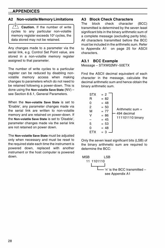
A3 Block Check CharactersThe block check character (BCC)transmitted is determined by the seven leastsignificant bits in the binary arithmetic sum ofa complete message (excluding parity bits).All characters transmitted before the BCCmust be included in the arithmetic sum. Referto Appendix A1 on page 25 for ASCIIcharacters.
A3.1 BCC ExampleMessage – STXW02MV–50ETX
Find the ASCII decimal equivalent of eachcharacter in the message, calculate thedecimal arithmetic sum and hence obtain thebinary arithmetic sum.
STX = 2R = 820 = 482 = 50M = 77V = 86– = 455 = 530 = 48ETX = 3
Only the seven least significant bits (LSB) ofthe binary arithmetic sum are required todetermine the BCC:
MSB LSB 11 1101110
‘n’ is the BCC transmitted –see Appendix A1
Arithmetic sum =494 decimal111101110 binary
A2 Non-volatile Memory Limitations
Caution. If the number of writecycles to any particular non-volatilememory register exceeds 104 cycles, thedata stored may not be retained.
Any changes made to a parameter via theserial link, e.g. Control Set Point value, arestored in a non-volatile memory registerassigned to that parameter.
The number of write cycles to a particularregister can be reduced by disabling non-volatile memory access when makingchanges to parameters which do not need tobe retained following a power-down. This isdone using the Non-volatile Save State (NV) –see Section 8.6.1, General Parameters.
When the Non-volatile Save State is set to'Enable', any parameter changes made viathe serial link are written to non-volatilememory and are retained on power-down. Ifthe Non-volatile Save State is set to 'Disable',parameter changes made via the serial linkare not retained on power down.
The Non-volatile Save State must be adjustedonly when necessary and must be reset tothe required state each time the instrument ispowered down, replaced with anotherinstrument or the host computer is powereddown.
…APPENDICES

PRODUCTS & CUSTOMER SUPPORTProducts
Automation Systems• for the following industries:
– Chemical & Pharmaceutical– Food & Beverage– Manufacturing– Metals and Minerals– Oil, Gas & Petrochemical– Pulp and Paper
Drives and Motors• AC and DC Drives, AC and DC Machines,
AC motors to 1kV• Drive systems• Force Measurement• Servo Drives
Controllers & Recorders• S ingle and Multi-loop Controllers• Circular Chart , Strip Chart and
Paperless Recorders• Paperless Recorders• Process Indicators
Flexible Automation• Industrial Robots and Robot Systems
Flow Measurement• Electromagnetic Magnetic Flowmeters• Mass Flow Meters• Turbine Flowmeters• Wedge Flow Elements
Marine Systems & Turbochargers• Electrical Systems• Marine Equipment• Offshore Retrofit and Referbishment
Process Analytics• Process Gas Analysis• Systems Integration
Transmitters• Pressure• Temperature• Level• Interface Modules
Valves, Actuators and Positioners• Control Valves• Actuators• Positioners
Water, Gas & Industrial AnalyticsInstrumentation
• pH, conductivity, and dissolved oxygentransmitters and sensors
• ammonia, nitrate, phosphate, silica,sodium, chloride, fluoride, dissolvedoxygen and hydrazine analyzers.
• Zirconia oxygen analyzers,katharometers, hydrogen purity andpurge-gas monitors, thermalconductivity.
Customer Support
ABB Automation provides a comprehensive after salesservice via our Worldwide Service Organization.Contact one of the following offices for details on yournearest Service and Repair Centre.
United KingdomABB Automation LimitedTel: +44 (0)1453-826-661Fax: +44 (0)1453-827-856
United States of AmericaABB Automation Inc.Instrumentation DivisionTel: +1 215-674-6000Fax: +1 215-674-7183
Client Warranty
Prior to installation, the equipment referred to inthis manual must be stored in a clean, dryenvironment, in accordance with the Company'spublished specification. Periodic checks must bemade on the equipment's condition.
In the event of a failure under warranty, thefollowing documentation must be provided assubstantiation:
1. A listing evidencing process operation andalarm logs at time of failure.
2. Copies of operating and maintenance recordsrelating to the alleged faulty unit.

IM/C
300–
SE
R Is
sue
4
The Company's policy is one of continuous productimprovement and the right is reserved to modify the informationcontained herein without notice.
© ABB 2001 Printed in UK (03.01)
ABB Automation LtdHoward Road, St. NeotsCambridgeshire, PE19 8EUUKTel: +44 (0)1480-475-321Fax: +44 (0)1480-217-948
ABB Automation Inc125 E. County Line RoadWarminster, PA 18974USATel: +1 215-674-6000Fax: +1 215-674-7183
ABB Automation has Sales & Customer Supportexpertise in over 100 countries worldwide
www.abb.com/automation