im iin i0101en-gb09 · calculation example for bending torque on flywheel housing below is an...
TRANSCRIPT

Installation manual
333
291
Engine
Industrial enginesDC09, DC13, DC16
OC16
01:01 Issue 9.0 en-GB © Scania CV AB 2018, Sweden
INSTALLATIONMANUAL
Changes from the previous issue............................................................................3
Engine suspension....................................................................................................4Suspension design requirements ......................................................................... 4Rigid engine suspension...................................................................................... 5Flexible engine suspension.................................................................................. 5Tightening torque for engine suspension ............................................................ 8Permissible installation and operating angles ..................................................... 9Flywheel housing .............................................................................................. 10Generator set dynamics ..................................................................................... 12Lifting the engine .............................................................................................. 13
Accessibility for maintenance and repairs ..........................................................16Installation requirements ................................................................................... 16Clearances ......................................................................................................... 17
Engine alignment...................................................................................................18Aligning engine and shafts ................................................................................ 19
Power transmission ...............................................................................................24Flexible coupling............................................................................................... 24Friction clutch ................................................................................................... 25
Transmission types ................................................................................................26Mechanical transmissions ................................................................................. 26Belt transmissions ............................................................................................. 26
Power take-off........................................................................................................28Front-mounted power take-offs......................................................................... 29Side-mounted power take-offs .......................................................................... 32Calculation example for torque take-off from power take-off .......................... 39
© Scania CV AB 201801:01 Issue 9.0 en-GB
Air compressor ...................................................................................................... 40
Torsional oscillations ............................................................................................ 41Data for torsional oscillation calculation.......................................................... 41Torsional oscillation calculations from Scania................................................. 42
General tightening torques for screw joints ....................................................... 43Specification of normal tightening torques....................................................... 43Tightening torques ............................................................................................ 44
Sticker “Powered by Scania”............................................................................... 47
, Sweden2

INSTALLATIONMANUAL
Changes from the previous issue
Changes from the previous issueThe changes made in this document compared with the previous issue are marked with a black line in the left-hand margin. The changes are also described below.
• Section Suspension design requirements has been made clearer.
• In section Insulators, maximum and minimum loads and dimensions for Scania insulators have been added.
• In section Tightening torque for engine suspension, a tightening sequence for the engine brackets has been added.
• Section Calculation example for bending torque on flywheel housing has been added.
• Working procedures for Lifting the engine have been added.
• Clearances for Downward facing centrifugal oil cleaner have been added.
• Section Flexible coupling has been made clearer.
• In section Power take-off, a text and illustration has been added, informing the reader that components from other manufacturers cannot be used in the belt trans-mission.
• Hydraulic diagram for hydraulic pump has been added.
• Calculation example for torque take-off from power take-off has been added.
• In section Data for torsional oscillation calculation, information has been added on what values Scania needs in order to approve an external torsional oscillation calculation.
© Scania CV AB 201801:01 Issue 9.0 en-GB
, Sweden3
INSTALLATIONMANUAL
Engine suspension
393
928
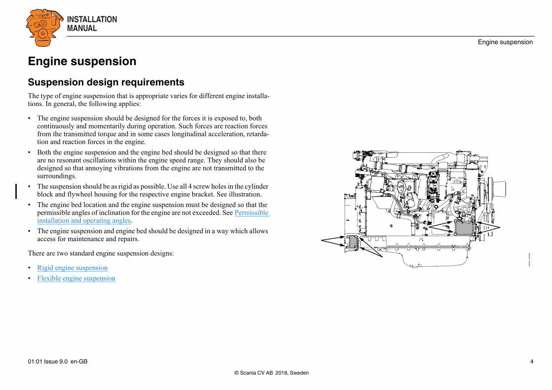
Engine suspensionSuspension design requirementsThe type of engine suspension that is appropriate varies for different engine installa-tions. In general, the following applies:
• The engine suspension should be designed for the forces it is exposed to, both continuously and momentarily during operation. Such forces are reaction forces from the transmitted torque and in some cases longitudinal acceleration, retarda-tion and reaction forces in the engine.
• Both the engine suspension and the engine bed should be designed so that there are no resonant oscillations within the engine speed range. They should also be designed so that annoying vibrations from the engine are not transmitted to the surroundings.
• The suspension should be as rigid as possible. Use all 4 screw holes in the cylinder block and flywheel housing for the respective engine bracket. See illustration.
• The engine bed location and the engine suspension must be designed so that the permissible angles of inclination for the engine are not exceeded. See Permissible installation and operating angles.
• The engine suspension and engine bed should be designed in a way which allows access for maintenance and repairs.
There are two standard engine suspension designs:
• Rigid engine suspension
• Flexible engine suspension
© Scania CV AB 2018, Sweden01:01 Issue 9.0 en-GB 4
INSTALLATIONMANUAL
Engine suspension
344
281
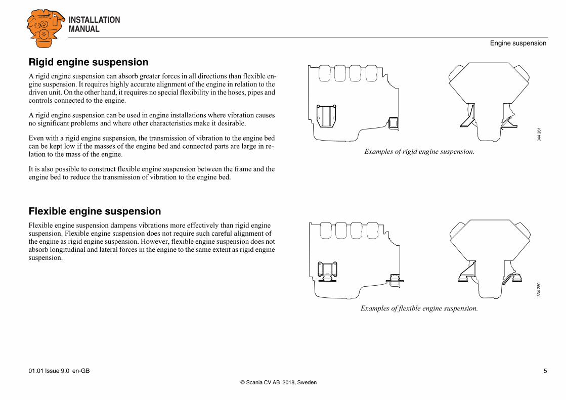
Examples of rigid engine suspension.
334
280
Examples of flexible engine suspension.
Rigid engine suspensionA rigid engine suspension can absorb greater forces in all directions than flexible en-gine suspension. It requires highly accurate alignment of the engine in relation to the driven unit. On the other hand, it requires no special flexibility in the hoses, pipes and controls connected to the engine.
A rigid engine suspension can be used in engine installations where vibration causes no significant problems and where other characteristics make it desirable.
Even with a rigid engine suspension, the transmission of vibration to the engine bed can be kept low if the masses of the engine bed and connected parts are large in re-lation to the mass of the engine.
It is also possible to construct flexible engine suspension between the frame and the engine bed to reduce the transmission of vibration to the engine bed.
Flexible engine suspensionFlexible engine suspension dampens vibrations more effectively than rigid engine suspension. Flexible engine suspension does not require such careful alignment of the engine as rigid engine suspension. However, flexible engine suspension does not absorb longitudinal and lateral forces in the engine to the same extent as rigid engine suspension.
© Scania CV AB 2018, Sweden01:01 Issue 9.0 en-GB 5
INSTALLATIONMANUAL
Engine suspension
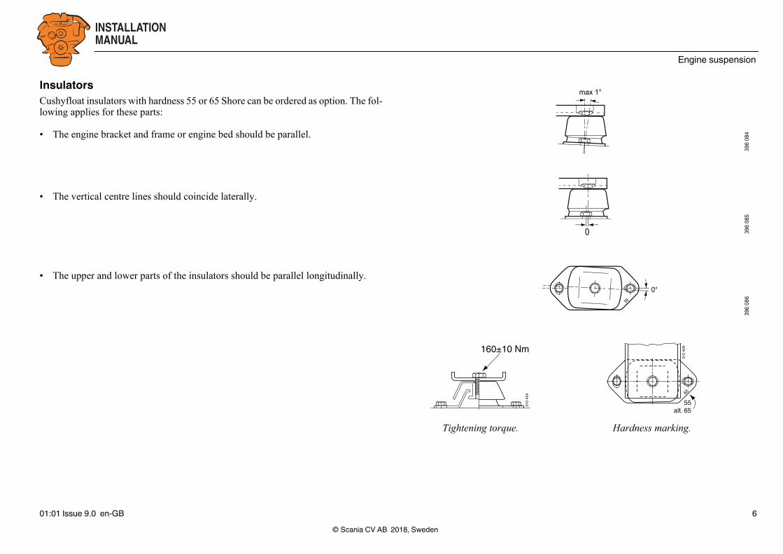
Tightening torque. Hardness marking.
max 1°
396
084
0 396
085
55
0°
396
086
310
404
160±10 Nm
310
405
55
55alt. 65
InsulatorsCushyfloat insulators with hardness 55 or 65 Shore can be ordered as option. The fol-lowing applies for these parts:
• The engine bracket and frame or engine bed should be parallel.
• The vertical centre lines should coincide laterally.
• The upper and lower parts of the insulators should be parallel longitudinally.
© Scania CV AB 2018, Sweden01:01 Issue 9.0 en-GB 6
INSTALLATIONMANUAL
Engine suspension
182
228
A
26
18
18
34
M20
394
808
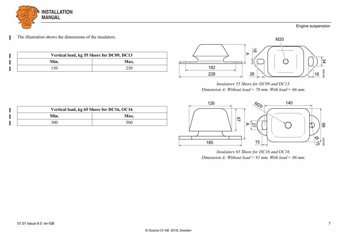
Insulators 55 Shore for DC09 and DC13.Dimension A: Without load = 70 mm. With load = 66 mm.
140
185
67
15
27
126
A 99
Ø 15
M20
394
807
Insulators 65 Shore for DC16 and OC16.Dimension A: Without load = 91 mm. With load = 86 mm.
The illustration shows the dimensions of the insulators.
Vertical load, kg 55 Shore for DC09, DC13
Min. Max.
150 250
Vertical load, kg 65 Shore for DC16, OC16
Min. Max.
300 500
© Scania CV AB 2018, Sweden01:01 Issue 9.0 en-GB 7

INSTALLATIONMANUAL
Engine suspension
1
34
2
394
815
Example of engine bracket.
Tightening torque for engine suspensionThe engine brackets can look different on different engine types, but all types of en-gine bracket are tightened crosswise.
1. Torque tighten screws 1 and 2.
2. Torque tighten screws 3 and 4.
3. Angle-tighten screws 1 and 2.
4. Angle-tighten screws 3 and 4.
Front engine suspension
Rear engine suspension
Type of screw Tightening torques
25 mm clamping length, M16, 10.9 130 Nm, 90°
50 mm clamping length, M16, 10.9 130 Nm, 135°
Type of screw Tightening torques
M14, 8.8 149 Nm
© Scania CV AB 2018, Sweden01:01 Issue 9.0 en-GB 8
INSTALLATIONMANUAL
Engine suspension
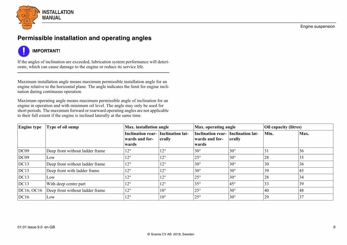
Max. operating angle Oil capacity (litres)
tion lat- Inclination rear-wards and for-wards
Inclination lat-erally
Min. Max.
30° 30° 31 36
25° 30° 28 35
30° 30° 30 36
30° 30° 39 45
25° 30° 28 34
35° 45° 33 39
25° 30° 40 48
25° 30° 29 37
Permissible installation and operating anglesIMPORTANT!
If the angles of inclination are exceeded, lubrication system performance will deteri-orate, which can cause damage to the engine or reduce its service life.
Maximum installation angle means maximum permissible installation angle for an engine relative to the horizontal plane. The angle indicates the limit for engine incli-nation during continuous operation.
Maximum operating angle means maximum permissible angle of inclination for an engine in operation and with minimum oil level. The angle may only be used for short periods. The maximum forward or rearward operating angles are not applicable to their full extent if the engine is inclined laterally at the same time.
Engine type Type of oil sump Max. installation angle
Inclination rear-wards and for-wards
Inclinaerally
DC09 Deep front without ladder frame 12° 12°
DC09 Low 12° 12°
DC13 Deep front without ladder frame 12° 12°
DC13 Deep front with ladder frame 12° 12°
DC13 Low 12° 12°
DC13 With deep centre part 12° 12°
DC16, OC16 Deep front without ladder frame 12° 10°
DC16 Low 12° 10°
© Scania CV AB 2018, Sweden01:01 Issue 9.0 en-GB 9

INSTALLATIONMANUAL
Engine suspension
Flywheel housingSilumin housings are supplied as standard on all industrial engines. The maximum permissible bending torque for a silumin housing is 10,000 Nm. This presumes that there are no axial loads from, for example, the propeller shaft, abnormal G forces or vibration.
For certain engine types, it is also possible to select a nodular iron flywheel housing. Nodular iron housings can dampen vibrations at certain engine speeds but increase vibrations at other engine speeds. Nodular iron is stronger than silumin and can there-fore tolerate greater bending and torsional forces.
The stronger nodular iron housings are recommended in installations where transport causes serious stress on the flywheel housing, such as in dumper type trucks or gen-erator sets with high outputs.
If it is difficult to determine the size and nature of the load, contact your nearest Sca-nia distributor.
© Scania CV AB 2018, Sweden01:01 Issue 9.0 en-GB 10
INSTALLATIONMANUAL
Engine suspension
377
153
LB
LA
FA FB
MAA B
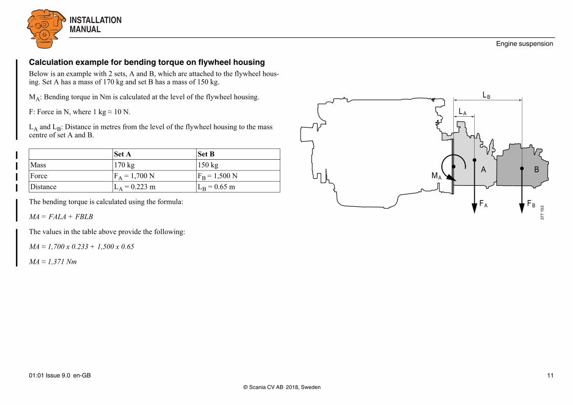
Calculation example for bending torque on flywheel housingBelow is an example with 2 sets, A and B, which are attached to the flywheel hous-ing. Set A has a mass of 170 kg and set B has a mass of 150 kg.
MA: Bending torque in Nm is calculated at the level of the flywheel housing.
F: Force in N, where 1 kg ≈ 10 N.
LA and LB: Distance in metres from the level of the flywheel housing to the mass centre of set A and B.
The bending torque is calculated using the formula:
MA = FALA + FBLB
The values in the table above provide the following:
MA ≈ 1,700 x 0.233 + 1,500 x 0.65
MA ≈ 1,371 Nm
Set A Set B
Mass 170 kg 150 kg
Force FA = 1,700 N FB = 1,500 N
Distance LA = 0.223 m LB = 0.65 m
© Scania CV AB 2018, Sweden01:01 Issue 9.0 en-GB 11
INSTALLATIONMANUAL
Engine suspension
5
4321
66
344
282
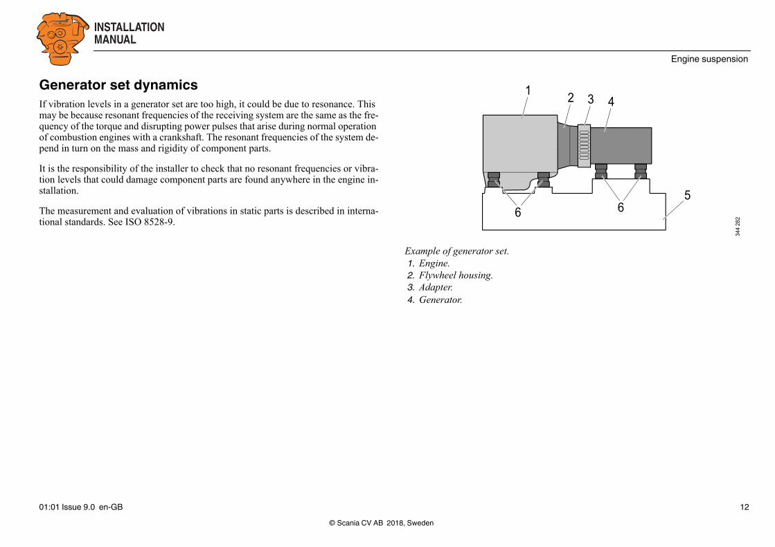
Example of generator set.1. Engine.2. Flywheel housing.3. Adapter.4. Generator.
Generator set dynamicsIf vibration levels in a generator set are too high, it could be due to resonance. This may be because resonant frequencies of the receiving system are the same as the fre-quency of the torque and disrupting power pulses that arise during normal operation of combustion engines with a crankshaft. The resonant frequencies of the system de-pend in turn on the mass and rigidity of component parts.
It is the responsibility of the installer to check that no resonant frequencies or vibra-tion levels that could damage component parts are found anywhere in the engine in-stallation.
The measurement and evaluation of vibrations in static parts is described in interna-tional standards. See ISO 8528-9.
© Scania CV AB 2018, Sweden01:01 Issue 9.0 en-GB 12

INSTALLATIONMANUAL
Engine suspension
max 30°
394
809
Lifting the engineDC09 and DC13
WARNING!
The engine lifting eyes are dimensioned for lifting the engine only, not the engine to-gether with connected equipment (e.g. alternator, gearbox) or frame. All 3 lifting eyes must be used.
The lifting eyes are sized to cope with a maximum angle of 30°.
ToolNumber Designation Illustration
98 094 Lifting chain
587 308 Ratchet lever hoist
99 637 Lifting eye
142
033
142
730
319
634
© Scania CV AB 2018, Sweden01:01 Issue 9.0 en-GB 13
INSTALLATIONMANUAL
Engine suspension
394
811
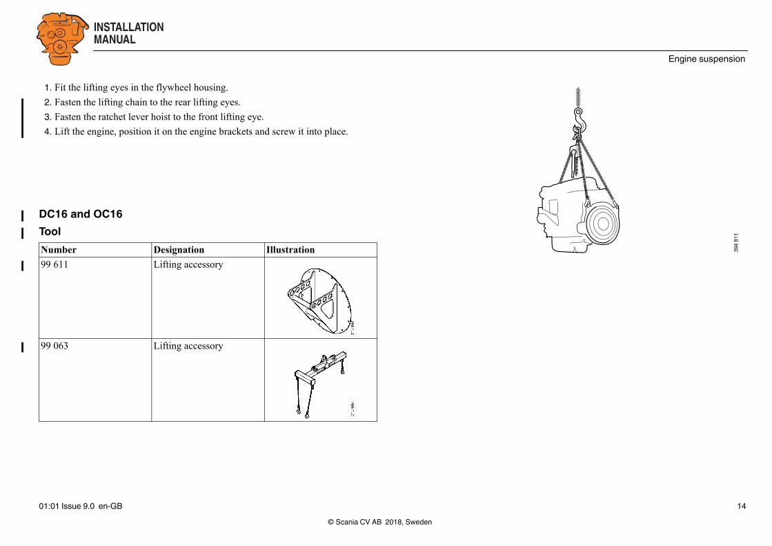
1. Fit the lifting eyes in the flywheel housing.
2. Fasten the lifting chain to the rear lifting eyes.
3. Fasten the ratchet lever hoist to the front lifting eye.
4. Lift the engine, position it on the engine brackets and screw it into place.
DC16 and OC16ToolNumber Designation Illustration
99 611 Lifting accessory
99 063 Lifting accessory
© Scania CV AB 2018, Sweden01:01 Issue 9.0 en-GB 14

INSTALLATIONMANUAL
Engine suspension
max 30°
394
809
1
2 394
813
WARNING!
The engine lifting eyes are dimensioned for lifting the engine only, not the engine to-gether with connected equipment (e.g. alternator, gearbox) or frame.
The lifting eyes are sized to cope with a maximum angle of 30°.
1. Fit lifting accessory 99 611 on the flywheel housing (2).
2. Fit lifting accessory 99 063 in the front lifting eye (1) and in lifting accessory 99 611 (2).
3. Lift the engine, position it on the engine brackets and screw it into place.
© Scania CV AB 2018, Sweden01:01 Issue 9.0 en-GB 15
INSTALLATIONMANUAL
Accessibility for maintenance and repairs
Accessibility for maintenance and repairsInstallation requirementsThe installer is responsible for ensuring accessibility for maintenance and repairs.
Note:There must be sufficient space at installation so that standard times for maintenance and repairs can be attained.
The following requirements for accessibility must be met:
• Canopies and connected components must be designed so that the engine can be removed and fitted relatively easily.
• In the case of static engine installations, there should be permanent securing points for lifting devices above the unit.
• The fuel system must be easily accessible for maintenance and bleeding.
• It should be possible to read the graduations on the flywheel when adjusting valves and unit injectors.
• It should be possible to remove and fit the cylinder head, rocker covers and push-rods while leaving the engine in place.
• It must be possible to remove the oil sump in order to renew cylinder liners or pis-tons with the engine in place.
• It should be easy to fill and drain oil. In addition, the oil dipstick must be easily accessible.
• Centrifugal oil cleaners and oil filters must be easy to access for maintenance and for renewal.
• It should be easy to fill and drain coolant.
• Engine air filters must be located so that they are easy to access for the renewal of filter elements.
© Scania CV AB 201801:01 Issue 9.0 en-GB
It must also be easy to carry out maintenance on the following components:
• Turbocharger
• Starter motor
• Generator
• Coolant pump
• Radiator
• Cooling fan
• Flexible coupling or friction clutch
• Batteries
• Crankcase ventilation filter
For gas engines, it must also be easy to carry out maintenance on the following com-ponents:
• Spark plug
• Flame arrestor
• Gas mixer insert
• Electric throttles
• Gas regulator
• Lambda sensor
, Sweden16

INSTALLATIONMANUAL
Accessibility for maintenance and repairs
F
B
F
A
F
344
285
Clearances for DC09 and DC13.
F
A A
B
F
F
F
344
286
Clearances for DC16 and OC16.
ClearancesThe most important clearances are shown in the table and illustrations. The specified measurements apply to the largest standard equipment.
Measure-ment
Clearance in mm For maintenance or renewal of
DC09 DC13 DC16 OC16
A 150 150 150 380 cylinder liner, cylinder head, etc.
B 250 260 260 260 oil sump1
1. If the oil sump has a special design, these values do not apply.
F 400 400 400 500 various units
© Scania CV AB 2018, Sweden01:01 Issue 9.0 en-GB 17

INSTALLATIONMANUAL
Engine alignment
240
160
394
028
Downward facing centrifugal oil cleanerFor engines with a downward facing centrifugal oil cleaner, the clearances in the il-lustration apply.
Engine alignmentThe alignment of the engine in relation to the driven unit is very important in order to prevent malfunctions. Otherwise there is a risk of vibration and serious stress to the crankshaft, engine brackets, drive shaft and flexible coupling or friction clutch, causing damage which is costly to repair.
Alignment should be checked regularly on certain vibration-sensitive engine instal-lations. Adjust engine alignment with shims between the engine bed and the engine suspension.
The alignment requirements are reduced if a flexible coupling is installed between the engine and the driven unit. Refer to the data on the flexible coupling concerned for permissible deviations.
Relatively large deviations are permissible with flexible couplings. However, align-ment should be as accurate as possible to achieve low vibration and a long service life on the flexible coupling.
For more information, see Flexible coupling.
© Scania CV AB 2018, Sweden01:01 Issue 9.0 en-GB 18

INSTALLATIONMANUAL
Engine alignment
Aligning engine and shaftsStart from the driven shaft when aligning. First check that this is straight. Alignment is made easier if the engine brackets are equipped with adjusting screws for vertical and lateral adjustment. However, permanent setting should be made using shims.
Adjust the engine alignment vertically using shims between the engine bed and en-gine suspension and laterally by moving the engine sideways on the surface. Shafts with flanges: Start by aligning roughly and secure the engine to its engine bed. Mate the flanges (1) so that the guide edge of one flange enters the guide hole of the other flange.
Calculation of angular deviation1. Fit the stand for the dial gauge (2) to the driving flange.
2. Align the tip of the dial gauge with the axial surface of the other flange as far as possible.
3. Zero the dial gauge at 12 o'clock.
4. Place one of the retaining screws through both flanges without tightening it.
5. Turn the shafts at the same time and read the dial gauge at intervals of 90° while turning one revolution. Enter the values in the table. Make sure you use the right signs.
6. Calculate the angular deviation between the shafts using the values.
Location of measurement point Measurement value1
1. + means inwards and - means outwards
12 o'clock ±0 mm
3 o'clock ± mm
6 o'clock ± mm
9 o'clock ± mm
© Scania CV AB 201801:01 Issue 9.0 en-GB
2
1 344
283
Measuring angular deviation.
, Sweden19
INSTALLATIONMANUAL
Engine alignment
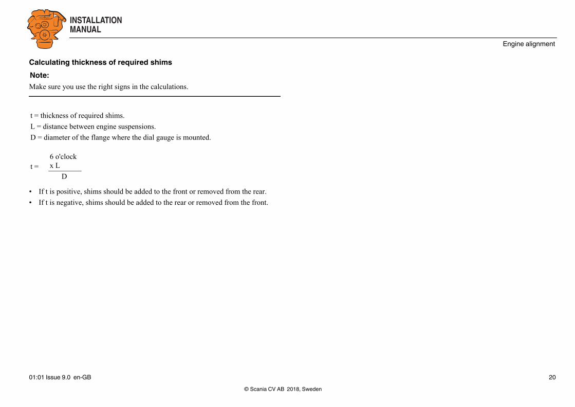
Calculating thickness of required shimsNote:Make sure you use the right signs in the calculations.
• If t is positive, shims should be added to the front or removed from the rear.
• If t is negative, shims should be added to the rear or removed from the front.
t = thickness of required shims.
L = distance between engine suspensions.
D = diameter of the flange where the dial gauge is mounted.
t =6 o'clock x L
D
© Scania CV AB 2018, Sweden01:01 Issue 9.0 en-GB 20

INSTALLATIONMANUAL
Engine alignment
344
284
Calculating lateral adjustmentNote:Make sure you use the right signs in the calculations.
• If s is positive, the front engine suspension must be moved to the right.
• If s is negative, the front engine suspension must be moved to the left.
Checking parallelism of the flanges with a feeler gaugeAngular deviation between the shaft centrelines can also be checked using a 0.1 mm feeler gauge. Do this by measuring the distance between the surfaces of the flanges at the outer edges.
During measurement, the engine must be tightened onto the engine bed.
s = lateral displacement of engine suspension.
L = distance between engine suspensions.
D = diameter of the flange where the dial gauge is mounted.
s =(3 o'clock - 9 o'clock) x L
D
© Scania CV AB 2018, Sweden01:01 Issue 9.0 en-GB 21
INSTALLATIONMANUAL
Engine alignment
2
1 344
287
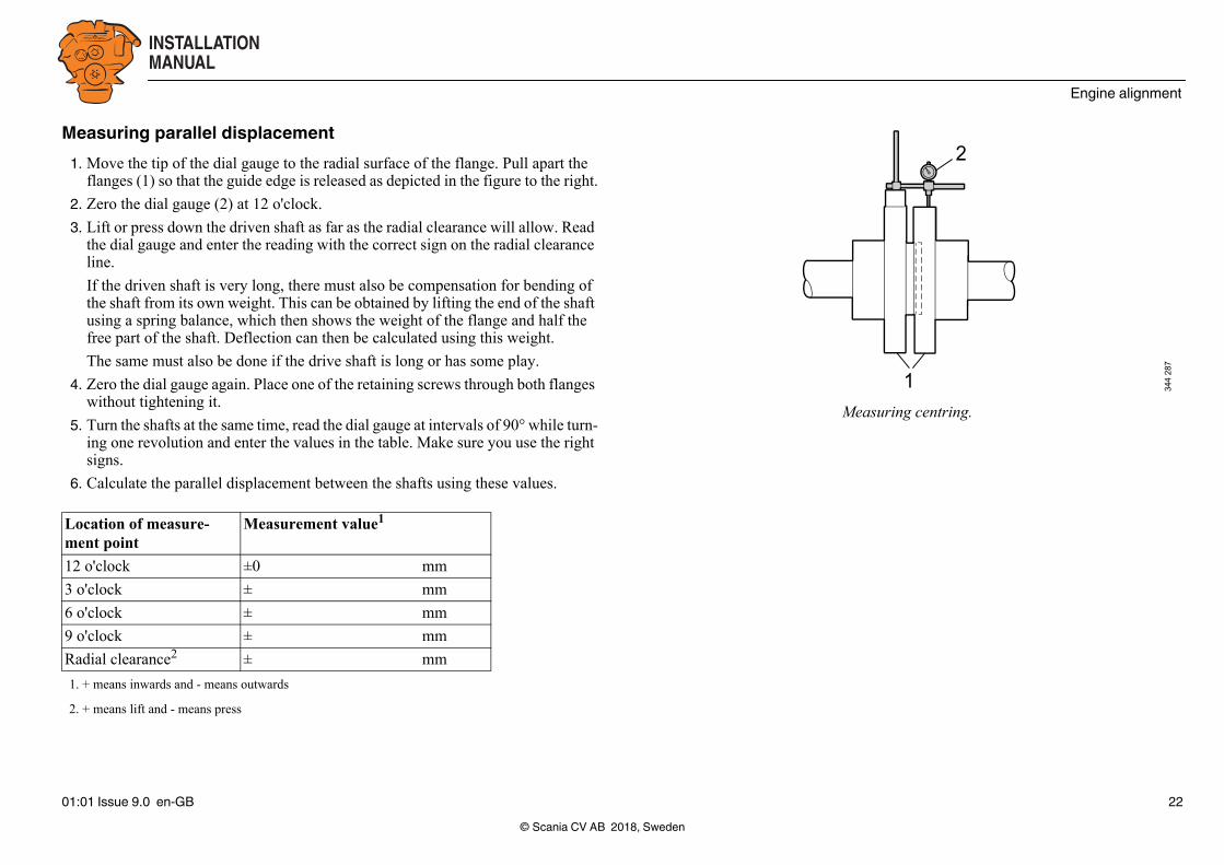
Measuring centring.
Measuring parallel displacement1. Move the tip of the dial gauge to the radial surface of the flange. Pull apart the
flanges (1) so that the guide edge is released as depicted in the figure to the right.
2. Zero the dial gauge (2) at 12 o'clock.
3. Lift or press down the driven shaft as far as the radial clearance will allow. Read the dial gauge and enter the reading with the correct sign on the radial clearance line.
If the driven shaft is very long, there must also be compensation for bending of the shaft from its own weight. This can be obtained by lifting the end of the shaft using a spring balance, which then shows the weight of the flange and half the free part of the shaft. Deflection can then be calculated using this weight.
The same must also be done if the drive shaft is long or has some play.
4. Zero the dial gauge again. Place one of the retaining screws through both flanges without tightening it.
5. Turn the shafts at the same time, read the dial gauge at intervals of 90° while turn-ing one revolution and enter the values in the table. Make sure you use the right signs.
6. Calculate the parallel displacement between the shafts using these values.
Location of measure-ment point
Measurement value1
1. + means inwards and - means outwards
12 o'clock ±0 mm
3 o'clock ± mm
6 o'clock ± mm
9 o'clock ± mm
Radial clearance2
2. + means lift and - means press
± mm
© Scania CV AB 2018, Sweden01:01 Issue 9.0 en-GB 22

INSTALLATIONMANUAL
Engine alignment
Calculating parallel displacementNote:Make sure you use the right signs.
Shafts without flangeIf both shaft ends are free during alignment, alignment can be checked using a dial gauge (2) set up as depicted in the figure. Readings should be taken with the tip of the dial gauge in two different places at least 200 mm apart axially. Turn the shafts at the same time and read the results on the dial gauge.
Permissible deviationsAfter taking measurements, a final check should be made. All screws, except those for the flange joint, should be tightened to the torque specified by the manufacturer. Upon measurement, deviation should not exceed 0.1 mm.
The requirements for the accuracy of the alignment can vary depending on the design of the engine installation. If the requirements for accuracy are lower, the permissible deviation may be greater than indicated above.
Vertical Lateral
t =6 o'clock + clear-
ance t = 3 o'clock + 9
o'clock
2 2
© Scania CV AB 201801:01 Issue 9.0 en-GB
2
344
288
Measuring with free shaft ends.
, Sweden23

INSTALLATIONMANUAL
Power transmission
Power transmissionEngine torque is normally transmitted to the driven unit in one of the following ways:
• Through a flexible coupling which cannot be disengaged, e.g. engines for gener-ator sets.
• Through a friction coupling, possibly also used together with a flexible coupling, and via a reduction gear, torque converter or belt transmission.
Flexible couplingMany engine installations require a flexible coupling between the engine and the driven unit to dampen irregularities in the system. The flexible coupling allows a cer-tain angular displacement towards the output shaft. It also has an effect of evening out irregularities in torque and therefore counteracts the tendency towards torsional oscillation. The correct choice of rubber hardness reduces the stress on the driven units.
The rubber hardness also affects the resonance frequency of the system. Therefore, it is important to be aware of the system resonance frequency in order to avoid that it coincides with the engine firing frequency at the desired engine speed. The reso-nance frequency calculation is included in Scania's torsional oscillation calculation.
© Scania CV AB 201801:01 Issue 9.0 en-GB
Carry out a torsional oscillation calculation before selecting a flexible coupling. When a flexible coupling is recommended based on the torsional oscillation calcula-tion, it is important that the flexible coupling installed and other transmission equip-ment follow the precise specification of the calculation.
For operation with generator set, there must be no play in the flexible coupling be-tween the engine and generator.
Information about suitable flexible couplings can be obtained from your nearest Sca-nia distributor or from the flexible coupling supplier.
Note:For gas engines in generator operation, a single-bearing generator with a friction clutch should be installed so that the engine control unit is capable of detecting mis-firing. If a flexible coupling is required in the installation, misfire detection must be deactivated in SDP3.
, Sweden24

INSTALLATIONMANUAL
Power transmission
Friction clutchIndustrial installations use two types of friction clutches, a vehicle clutch and an in-dustrial clutch. The industrial clutch has a greater capacity, i.e. it can transfer greater torque than the vehicle clutch. There are many different makes of industrial clutches on the market. It is important that the industrial clutch is not subjected to loads that could cause overloading of the industrial clutch bearings. Vehicle clutches are used together with conventional multi-ratio gearboxes, where the transmission can be dis-engaged.
Single-bearing friction clutches may not be subjected to large lateral forces and are therefore most often used in engine installations where torque is transmitted straight to the rear via a propeller shaft or similar power transmission. For heavier operation, e.g. belt transmissions where large lateral forces arise, Scania recommends using friction clutches which absorb lateral forces in the main bearings. This type of fric-tion clutch does not have a support bearing in the flywheel.
It is also important that a remote-controlled friction clutch has no remaining pressure on the release bearing, neither when engaged nor disengaged, since the release bear-ing is then subject to rapid wear. For this type of clutch operation, we recommend the use of ball bearings as release bearings.
See the illustration in the Belt transmission in multi-engine installations section for how a belt transmission should be set up in a multi-engine installation.
If the engine installation has a clutch other than a friction type, e.g. hydrodynamic (wet) clutch, the necessary installation instructions can be obtained from the clutch supplier.
Note:The crankshaft should not be subjected to axial pressure from the friction clutch. Check this after fitting.
© Scania CV AB 201801:01 Issue 9.0 en-GB
, Sweden25

INSTALLATIONMANUAL
Transmission types
Transmission typesMechanical transmissionsMechanical transmissions are the most common type on single engine installations. These may be multi-ratio gearboxes or reduction gears.
If an engine is supplied without a gear or gearbox, affected parts of the engine (fly-wheel, flywheel housings etc.) can still be adapted so that the gears and torque con-verters available on the market can be fitted.
For certain gears and torque converters, there are requirements to ensure that the ax-ial run-out and radial run-out are not too great. Therefore check at installation to en-sure that the supplier's requirements are met.
Belt transmissionsBelt transmissions are appropriate in, for instance, multi-engine installations where two or more engines drive a common output shaft. One of the advantages of a belt transmission is that it is easy to adapt to the appropriate gear ratio.
The belt transmission functions to some extent as a flexible coupling, runs silently and has a long service life. Apart from checking belt tension and alignment, belt transmissions do not require any special maintenance.
© Scania CV AB 201801:01 Issue 9.0 en-GB
There are belt transmissions with different types of belts, such as single V-belts and devices consisting of two or more V-belts coupled together.
Which belt type to choose depends on several factors. More information and help in dimensioning a belt transmission can be obtained from the belt manufacturer.
Large lateral forces may arise during belt operation. Accurate alignment and check-ing of the belt tension are therefore necessary. A different belt tension results in in-creased bearing load and displacement of the centre of the load. The lateral loading can be reduced by e.g. changing the size of the pulley.
If there are large lateral forces on a pulley which is directly connected to an industrial clutch, the pulley must be seated on both sides in separate bearing brackets.
The manufacturer can provide information about permissible lateral forces and belt tensioning for belt transmission in each case.
, Sweden26
INSTALLATIONMANUAL
Transmission types
A B
Ø0.8
1 2 1 3 4 5
332
917
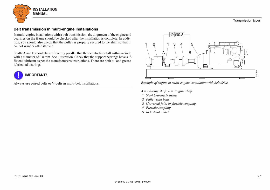
Example of engine in multi-engine installation with belt drive.
A = Bearing shaft. B = Engine shaft.1. Steel bearing housing.2. Pulley with belts.3. Universal joint or flexible coupling.4. Flexible coupling.5. Industrial clutch.
Belt transmission in multi-engine installationsIn multi-engine installations with a belt transmission, the alignment of the engine and bearings on the frame should be checked after the installation is complete. In addi-tion, you should also check that the pulley is properly secured to the shaft so that it cannot wander after start-up.
Shafts A and B should be sufficiently parallel that their centrelines fall within a circle with a diameter of 0.8 mm. See illustration. Check that the support bearings have suf-ficient lubricant as per the manufacturer's instructions. There are both oil and grease lubricated bearings.
IMPORTANT!
Always use paired belts or V-belts in multi-belt installations.
© Scania CV AB 2018, Sweden01:01 Issue 9.0 en-GB 27
INSTALLATIONMANUAL
Power take-off
1 2
393
930
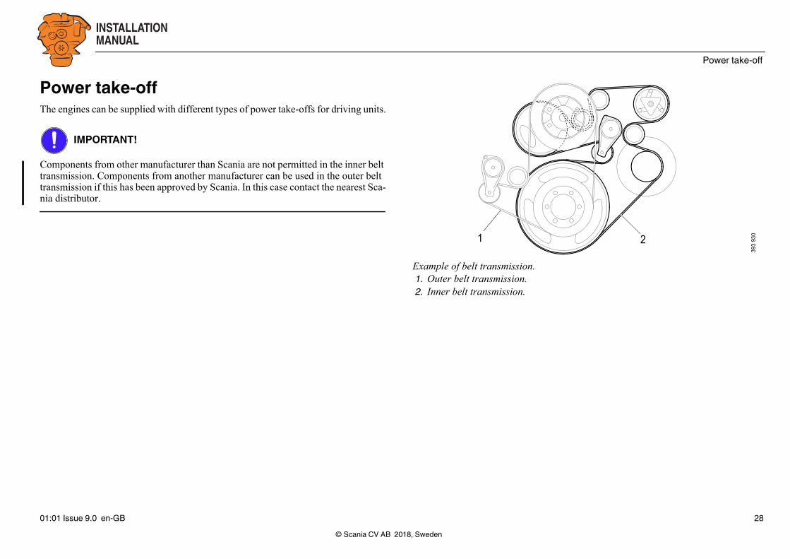
Example of belt transmission.1. Outer belt transmission.2. Inner belt transmission.
Power take-offThe engines can be supplied with different types of power take-offs for driving units.
IMPORTANT!
Components from other manufacturer than Scania are not permitted in the inner belt transmission. Components from another manufacturer can be used in the outer belt transmission if this has been approved by Scania. In this case contact the nearest Sca-nia distributor.
© Scania CV AB 2018, Sweden01:01 Issue 9.0 en-GB 28

INSTALLATIONMANUAL
Power take-off
344
289
344
290
344
291
Front-mounted power take-offs
Example of shaft journal for direct connection of flexible coupling.
Example of pulley on crankshaft.
Example of shaft journal and pulley.
© Scania CV AB 2018, Sweden01:01 Issue 9.0 en-GB 29

INSTALLATIONMANUAL
Power take-off
344
292
Connection of flexible coupling to front end of crankshaftThe engine must be equipped with a shaft journal or flange driver which is mounted on the crankshaft hub so that a flexible coupling (Centa A type, size 30 or 50) can be connected at the front end of the crankshaft.
The transmissible torque and power in the case of direct connection to the front end of the crankshaft are limited primarily by engine type and the type of joint between the crankshaft and hub.
Crankshaft pulley with two or more belt groovesIn order to fit this type of pulley, the cooling fan must be moved forwards.
The belt grooves are designed for 12.5 mm (0.5") narrow V-belts, but A section V-belts can also be used. The transmission capacity of the V-belts determines the power available. Therefore it is important that the belt manufacturer's instructions are ad-hered to when calculating transmissible power.
As when connecting a flexible coupling or industrial clutch to the front end of the crankshaft, transmissible torque and power between the crankshaft and pulley are limited by engine type and the type of joint as shown in the following tables.
In order to avoid impermissible radial forces at the front end of the crankshaft when there are many belts in the transmission, the driven units should be positioned so that the forces balance each other out.
© Scania CV AB 2018, Sweden01:01 Issue 9.0 en-GB 30

INSTALLATIONMANUAL
Power take-off
Torque take-off and transmissible power from the front end of the crankshaftThe tables below show the maximum torque take-off and transmissible power at dif-ferent engine speeds.
Note:With the Centa A coupling size 30, torque take-off is limited to max. 400 Nm.
Max. torque take offs for screw joints (Nm)
DC09 DC13 DC16
800 1,200 800
Engine speed (rpm) Transmissible power
DC09, DC16 DC13
1,500 125 kW 188 kW
1,800 151 kW 226 kW
1,900 160 kW 239 kW
2,000 168 kW 251 kW
2,100 176 kW 264 kW
© Scania CV AB 201801:01 Issue 9.0 en-GB
, Sweden31
INSTALLATIONMANUAL
Power take-off
Side-mounted power take-offsThe maximum torque that can be taken off from units connected to power take-offs is indicated on the following pages.
The specified maximum torque assumes that the driven units have a relatively even drive torque, e.g. generators or vane pumps.
IMPORTANT!
In the case of units which have highly pulsed torque, e.g. piston pumps or piston compressors with one or two cylinders, the permissible torque must be reduced. The torque reduction is needed so that the average torque does not exceed the permissible torque for continuous operation and the peak torque does not exceed the maximum torque for intermittent operation.
When reducing permissible torque, consideration should be given to the torque re-ductions specified by the manufacturer of belts and flexible couplings. Also assess whether connected units may have an effect on the crankshaft and cause torsional os-cillations in the shaft system.
© Scania CV AB 201801:01 Issue 9.0 en-GB
IMPORTANT!
Side-mounted power take-offs facing rearwards are not designed for driving without a load. If these power take-offs are not loaded, they must be removed. Otherwise, parts from the bearing housing may get into the engine and cause a breakdown.
Scania also recommends that SAE B power take-offs facing forwards are removed if they are not to be loaded.
If several different side-mounted power take-offs are used, the maximum permitted total torque take-off is 600 Nm.
The maximum permissible bending torque for all side-mounted power take-offs with SAE B connection is 30 Nm. This applies to all engine types.
, Sweden32

INSTALLATIONMANUAL
Power take-off
361
904
Side-mounted power take-offs for DC09 and DC13Power take-off 1The power take-off is located on the right of the rear of the engine. The illustration shows the direction of rotation for the power take-off.
Direction Connection Rotation Max. torque take-off
Gear ratio
Backwards SAE B 300 Nm 1:1.19
Transmissible powerEngine speed (rpm) Transmissible power
1,200 45 kW
1,500 56 kW
1,800 67 kW
1,900 71 kW
2,000 71 kW
2,100 71 kW
2,200 71 kW
© Scania CV AB 2018, Sweden01:01 Issue 9.0 en-GB 33
INSTALLATIONMANUAL
Power take-off
361
905
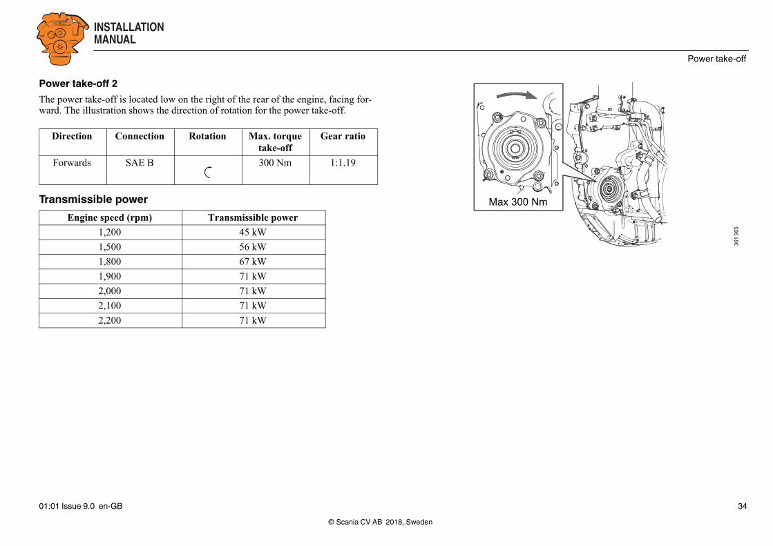
Power take-off 2The power take-off is located low on the right of the rear of the engine, facing for-ward. The illustration shows the direction of rotation for the power take-off.
Direction Connection Rotation Max. torque take-off
Gear ratio
Forwards SAE B 300 Nm 1:1.19
Transmissible powerEngine speed (rpm) Transmissible power
1,200 45 kW
1,500 56 kW
1,800 67 kW
1,900 71 kW
2,000 71 kW
2,100 71 kW
2,200 71 kW
© Scania CV AB 2018, Sweden01:01 Issue 9.0 en-GB 34

INSTALLATIONMANUAL
Power take-off
Max 100 Nm
332
915
Power take-off 3The power take-off is located on the left of the rear of the engine. The illustration shows the direction of rotation for the power take-off.
Direction Connection Rotation Max. torque take-off
Gear ratio
Backwards SAE A 100 Nm 1:1.71
Transmissible powerEngine speed (rpm) Transmissible power
1,200 21 kW
1,500 27 kW
1,800 32 kW
1,900 34 kW
2,000 34 kW
2,100 34 kW
2,200 34 kW
© Scania CV AB 2018, Sweden01:01 Issue 9.0 en-GB 35

INSTALLATIONMANUAL
Power take-off
M26 x 1.5
M16 x 1.5
393
924
Hydraulic pumpA standard hydraulic pump can also be fitted in the same location as power take-off 3, i.e. on the left of the rear of the engine. This hydraulic pump does not have an in-tegrated pressure limiting valve. Such a valve must therefore be installed in the sys-tem.
Note:When the hydraulic pump is installed, the tank must be positioned higher than the hy-draulic pump for the pump to have an even flow.
A hydraulic diagram for the hydraulic pumps is included in section Hydraulic dia-gram for hydraulic pump.
© Scania CV AB 2018, Sweden01:01 Issue 9.0 en-GB 36
INSTALLATIONMANUAL
Power take-off
361
906
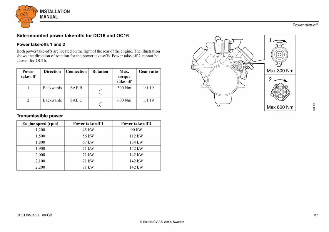
Side-mounted power take-offs for DC16 and OC16Power take-offs 1 and 2Both power take-offs are located on the right of the rear of the engine. The illustration shows the direction of rotation for the power take-offs. Power take-off 2 cannot be chosen for OC16.
Power take-off
Direction Connection Rotation Max. torque take-off
Gear ratio
1 Backwards SAE B 300 Nm 1:1.19
2 Backwards SAE C 600 Nm 1:1.19
Transmissible powerEngine speed (rpm) Power take-off 1 Power take-off 2
1,200 45 kW 90 kW
1,500 56 kW 112 kW
1,800 67 kW 134 kW
1,900 71 kW 142 kW
2,000 71 kW 142 kW
2,100 71 kW 142 kW
2,200 71 kW 142 kW
© Scania CV AB 2018, Sweden01:01 Issue 9.0 en-GB 37

INSTALLATIONMANUAL
Power take-off
M26 x 1.5
M16 x 1.5M16 x 1.5
393
922
3
1
2
394
814
1. Outlet.2. Intake.3. Injector.
Hydraulic pumpOn DC engines, a standard hydraulic pump can be fitted on the front right-hand side of the engine. The hydraulic pump is driven by the transmission via gears and the gear ratio is 1:1.75. This hydraulic pump does not have an integrated pressure limit-ing valve. Such a valve must therefore be installed in the system.
Note:When the hydraulic pump is installed, the tank must be positioned higher than the hy-draulic pump for the pump to have an even flow.
Hydraulic diagram for hydraulic pumpThe hydraulic diagram is valid for all hydraulic pumps. However, the hydraulic pump for DC16 has 2 outlets.
© Scania CV AB 2018, Sweden01:01 Issue 9.0 en-GB 38
INSTALLATIONMANUAL
Power take-off
Calculation example for torque take-off from power take-offThe torque take-off is calculated using the following formula:
kW x 9,550/(rpm) = Nm
ExampleA customer wishes a pump to deliver an output of 60 kW from a SAE B power take-off at 1,200 rpm. Is this allowed?
(60 kW x 9,550)/(1,200 rpm) = 478 Nm.
Max. torque take-off from the SAE B power take-off is 300 Nm. The conclusion is that the pump must not be connected to the power take-off.
© Scania CV AB 2018, Sweden01:01 Issue 9.0 en-GB 39

INSTALLATIONMANUAL
Air compressor
WE
T T
AN
K
12
8
61110
7 5
34
344
297
Air compressor without air dryer.
WE
T T
AN
K
12
3
9
86
1110
75
34
344
298
Air compressor with air dryer.
Air compressorAn engine can be equipped with an air compressor, e.g. for a vehicle with air brakes. The air compressor is delivered fitted on the engine and is driven by the engine tim-ing gear.
The installer acquires and is responsible for equipment connected to the air compres-sor.
Air to the air compressor should be taken from the engine air filter. A safety valve is fitted on the air compressor outlet. The safety valve opening pressure is 19 bar. The air compressor has a fuel economy function that is activated when the system is not in use.
The figures show how a normal system is made up:
1. Air compressor
2. Safety valve
3. Safety valve
4. Relief pipe
5. Test connection, filling
6. Check valve
7. Four-way safety valve
8. Relief valve
9. Air dryer
10. Drain tap
11. Tank
© Scania CV AB 2018, Sweden01:01 Issue 9.0 en-GB 40

INSTALLATIONMANUAL
Torsional oscillations
Torsional oscillationsTorsional oscillation arises in any shaft system which includes a combustion engine. Depending on the combination of the design of the shaft system and the operating speed, these oscillations may attain high amplitudes and therefore place great strain on the equipment. This may even lead to total breakdown in a part of the shaft sys-tem. This process may be very rapid.
IMPORTANT!
A torsional oscillation calculation (TVC) must be carried out for each unique engine installation and be documented in conjunction with the installation report. The cus-tomer or installer is responsible for performing this calculation.
If no torsional oscillation calculation has been carried out, or one has been carried out with unsatisfactory results, Scania Engines takes no financial or technical responsi-bility for installation problems or engine breakdowns caused by torsional oscilla-tions.
An unsuitably assembled installation may mean that it is necessary to limit the oper-ating speed range or refrain from using a front-mounted power take-off.
If a torsional oscillation calculation is made at the planning stage, it is usually possi-ble to easily adjust the shaft system to provide the safest engine installation.
© Scania CV AB 201801:01 Issue 9.0 en-GB
Data for torsional oscillation calculationForm for torsional oscillation calculation is available on Reflex.
Contact your nearest Scania distributor if you require help downloading the form or with the torsional oscillation calculation.
The following information is required for the calculation:
1. Engine type designation and classification society.
2. Operating speed and power.
3. The equipment fitted to the front and rear parts of the engine. State Scania part number.
4. Gear ratios.
5. Moment of inertia (j) or rotating mass (GD2) for component couplings, flanges, gears, shafts, propellers, generators etc. which rotate with the engine.
6. For couplings which can be disengaged, flexible couplings and similar, the val-ues for the component parts are required. If the values are not available, a draw-ing of the part is required showing diameters, widths and thicknesses of the component parts.
, Sweden41
INSTALLATIONMANUAL
Torsional oscillations
7. Dynamic rigidities of flexible couplings, shafts and belt transmissions. However, for shafts the material, length, outside and inside diameters, press-in lengths, shrink-on lengths and similar can be stated. For belt transmissions, we require shaft spacing, pulley diameters, belt type, number of belts and dynamic rigidities.
8. In the case of generator sets, a drawing of the generator shaft must be included with the calculation if it is to be approved by a classification society.
Scania needs the following values in order to approve an external torsional oscilla-tion calculation:
• The torsional strain (N/mm2) in the crankshaft for all operating speeds.
• The power loss (W) in the crankshaft torsion damper for all operating speeds.
This must be calculated both for normal operation and misfiring.
© Scania CV AB 201801:01 Issue 9.0 en-GB
Torsional oscillation calculations from ScaniaScania's torsional oscillation calculations are made with direct frequency response for all configurations up to 350 Hz in a linear system for the engine speeds in ques-tion. The calculation is based on technical data provided to Scania by the customer or manufacturer for parts forming part of the elastic mass system which are not man-ufactured by Scania.
An approved calculation forms a guarantee against damage caused by torsional os-cillations for all rotating parts from Scania that are included in the engine installation under Scania's general warranty commitments. The approval should not be regarded as a general system warranty in any other respect.
Scania only takes responsibility for parts in Scania's product range and not for any other parts. Scania can, however, give a warning if the calculation shows that non-Scania parts are subjected to high torsional amplitudes.
Together with the different subsuppliers, the supplier of the complete engine instal-lation to the customer should confirm the torsional capacity and provide approval for each component, based on the torsional oscillation calculation.
ISO 3046/V applies where appropriate.
The torsional oscillation calculation does not allow Scania to provide any statement or guarantee as regards hunting.
Torsional oscillation calculations may also be performed by companies other than Scania. The data required for performing these calculations can be obtained from SAIL.
, Sweden42

INSTALLATIONMANUAL
General tightening torques for screw joints
General tightening torques for screw jointsSpecification of normal tightening torquesThe specifications in the tables on the following pages show the normal tightening torques for screws and nuts.
The following conditions apply:
• A tolerance of ±15% applies to all values unless otherwise specified.
• All contact surfaces are to be clean and free of paint and the like.
• Screws and nuts are normally not lubricated regardless of surface treatment.
Union assembliesThe specified values apply with a tolerance of ±5%. The values apply to tightening with a counterhold.
Thread insertsThe specified tightening torques also apply to screw joints with a thread insert (Heli-Coil). Thread inserts often provide greater strength compared to a directly screwed thread. This creates a stronger screw joint in, for example, aluminium. For this rea-son, thread inserts are used in certain joints in Scania's production.
© Scania CV AB 201801:01 Issue 9.0 en-GB
, Sweden43

INSTALLATIONMANUAL
General tightening torques for screw joints
321
514
Tightening torquesHexagon screws, hexagon socket screws, Torx screws, hexagon nuts Metric thread, coarse pitchThread Strength class 8.8/8
Tightening torque (Nm)
M4 2.9
M5 6
M6 9.5
M8 24
M10 47
M12 84
M14 135
M16 210
M18 290
M20 420
M22 580
M24 730
© Scania CV AB 2018, Sweden01:01 Issue 9.0 en-GB 44
INSTALLATIONMANUAL
General tightening torques for screw joints
321
515
321
504
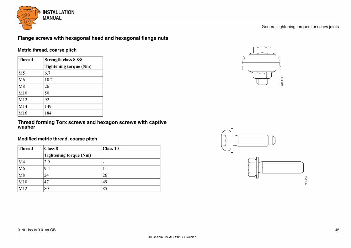
Flange screws with hexagonal head and hexagonal flange nuts
Metric thread, coarse pitch
Thread forming Torx screws and hexagon screws with captive washer
Modified metric thread, coarse pitch
Thread Strength class 8.8/8
Tightening torque (Nm)
M5 6.7
M6 10.2
M8 26
M10 50
M12 92
M14 149
M16 184
Thread Class 8 Class 10
Tightening torque (Nm)
M4 2.9 -
M6 9.4 11
M8 24 26
M10 47 49
M12 80 85
© Scania CV AB 2018, Sweden01:01 Issue 9.0 en-GB 45

INSTALLATIONMANUAL
General tightening torques for screw joints
stic pipe with brass fer-e and nut with rubber l
321
506
321
507
323
456
Stud end in threaded hole, strength class 8.8/8Metric thread, coarse pitchThe stud end must be tightened in the threaded hole so that the stud does not come loose when undoing the nut. To tighten the stud in the threaded hole the torque must just overcome the friction in the thread and generate a preload. The torque for locking is 50% of the normal torque for hexagon screws, hexagon socket screws, Torx screws and hexagon nuts.
Union nuts for ferruleThread Tightening torque (+/-15% Nm)
For pipe diam-eter
Steel pipe with greased steel nut
Plastic pipe with steel fer-rule and brass or steel nut
Plarulsea
M10x1 5 15 10 -
M12x1.5 6 20 10 -
M14x1.5 8 30 20 -
M16x1.5 10 40 25 15
M18x1.5 12 50 30 20
M20x1.5 12 55 35 -
M24x1.5 16 60 50 40
M30x2 22 120 - -
© Scania CV AB 2018, Sweden01:01 Issue 9.0 en-GB 46

INSTALLATIONMANUAL
Sticker “Powered by Scania”
P O W E R E D B Y
344
299
Sticker “Powered by Scania”Customers who so desire can order the sticker “Powered by Scania” to attach to the machine.
Machines operated using Scania's industrial and marine engines must be uniformly marked, therefore this is the only sticker which should be attached to the machine containing the engine.
Instructions for positioning the sticker are included. For more information, contact your nearest Scania distributor.
© Scania CV AB 2018, Sweden01:01 Issue 9.0 en-GB 47